

Page 1
SEALEDGAS COOKTOPS
CCG2423AND CCG2523
JGC7430 AND JGC7536
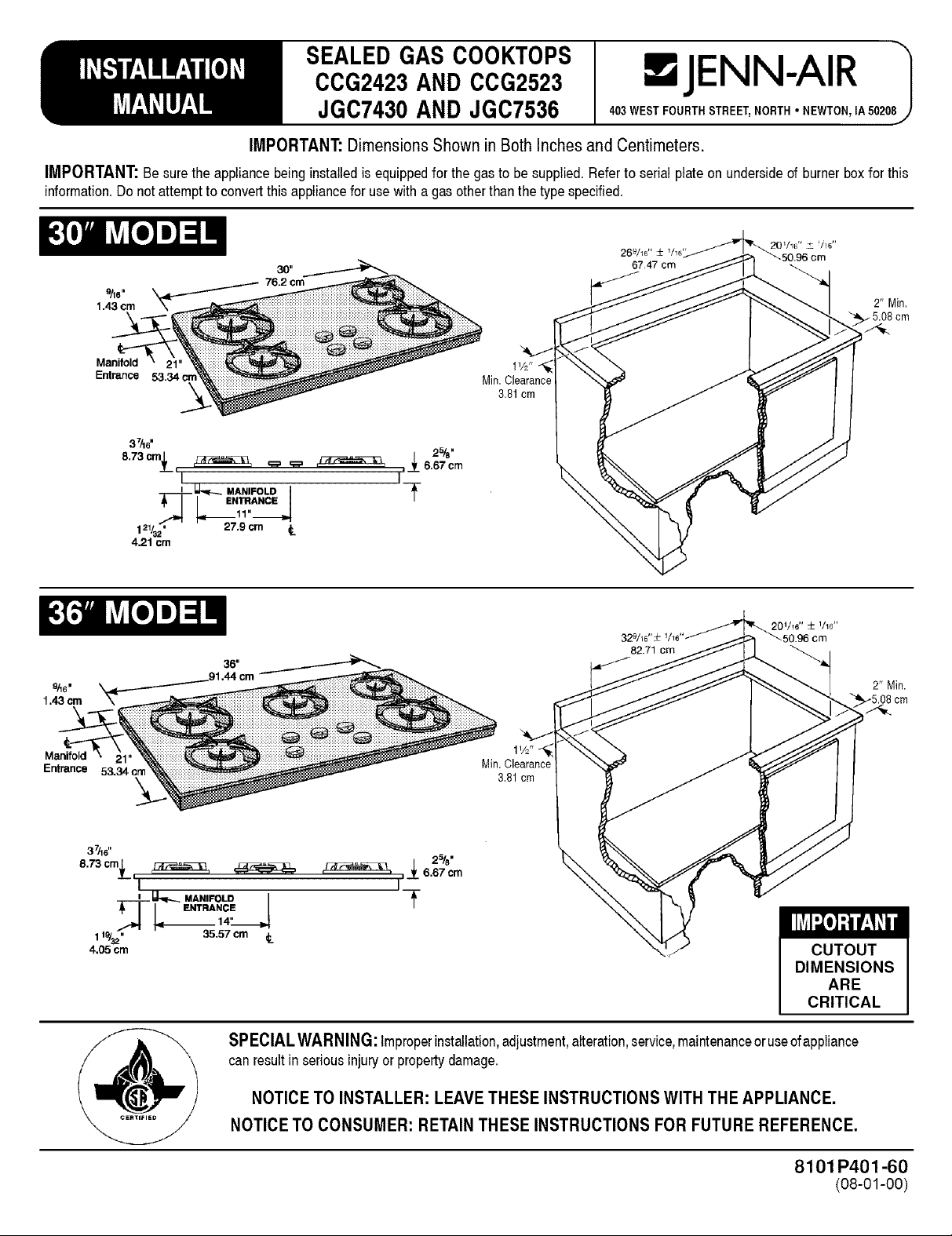
IMPORTANT:DimensionsShown in BothInchesand Centimeters.
IMPORTANT:Besurethe appliancebeinginstalledis equippedforthegasto besupplied.Referto serialplateon undersideofburnerboxfor this
information.Donotattemptto convertthis appliancefor usewitha gasotherthanthetype specified.
76.2 cm
"4
Manifold 1 V21' _
Entrance Min. Clearance
3.81cm
=JENN-AIR
403WEST FOURTHSTREET,NORTH° NEWTON,IA50208
2" Min.
5.08cm
37&6"
8.73__¢m_k,i_ _ _ _ ,_6.67cm
4.21 cm
9/16=
1.43cm
Manifold
Entrance 53.34 cm
37/16"
8.73 cmL, _
T-[-I ENTeNtE I
119/_.. 35.57 cm
4,05 cm
......_t_,_.._ MAN,FO_I
*II ENTRANClEJ
121/32" -- 27.9 cm
I
I _ MANIFOLD I
2%"
Lf
2%"
/
,,__ 6.67 cm
3.81cm
32_
82.71 cm
2" Min.
SPECIALWARNING:Improperinstallation,adjustment,alteration,service,maintenanceoruseofappliance
canresultinseriousinjuryor propertydamage.
NOTICETO INSTALLER:LEAVETHESE INSTRUCTIONSWITH THE APPLIANCE.
NOTICETO CONSUMER: RETAINTHESE INSTRUCTIONS FORFUTURE REFERENCE.
8101 P401-60
(08-01-00)
Page 2
LOCATIONOF YOUR JENN-AIRAPPLIANCE
Locatethisapplianceawayfromcombustiblematerialssuch aswindow
curtainsandcombustiblewalldecorations.
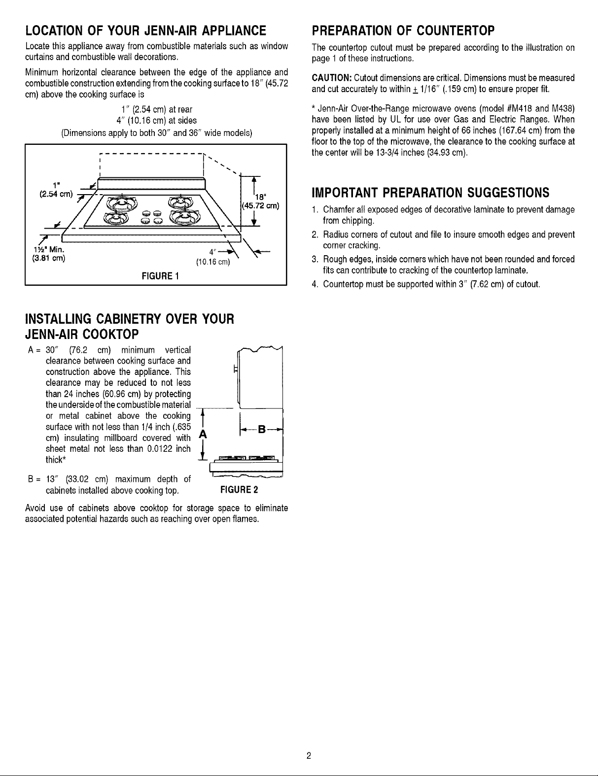
Minimumhorizontalclearancebetweenthe edge of the applianceand
combustibleconstructionextendingfromthe cookingsurfaceto 18"(45.72
cm)abovethecookingsurfaceis
1" (2.54cm)atrear
4" (10.16cm) atsides
(Dimensionsapplyto both30" and36" widemodels)
I
I
I
I a
(2.54 cm)
1½" Min.
(3.81 cm)
FIGURE 1
(10.16cm)
PREPARATIONOF COUNTERTOP
The countertopcutoutmustbe preparedaccordingto the illustrationon
page1oftheseinstructions.
CAUTION:Cutoutdimensionsarecritical.Dimensionsmustbemeasured
andcutaccuratelytowithin+_1/16" (.159cm)to ensureproperfit.
* Jenn-AirOver-the-Rangemicrowaveovens(model#M418and M438)
have been listed by UL for use over Gasand ElectricRanges.When
properlyinstalledataminimumheightof66 inches(167.64cm) fromthe
floorto thetop ofthe microwave,the clearanceto the cookingsurfaceat
the centerwillbe 13-3/4inches(34.93cm).
IMPORTANTPREPARATIONSUGGESTIONS
1. Chamferall exposededgesof decorativelaminatetopreventdamage
fromchipping.
2. Radiuscornersof cutoutandfile to insuresmoothedgesandprevent
cornercracking.
3. Roughedges,insidecornerswhichhavenot beenroundedandforced
fitscancontributeto crackingofthecountertoplaminate.
4. Countertopmustbesupportedwithin3" (7.62cm)of cutout.
INSTALLINGCABINETRYOVERYOUR
JENN-AIRCOOKTOP
A= 30" (76.2 cm) minimum vertical
clearancebetweencookingsurfaceand
constructionabovethe appliance.This
clearancemaybe reducedto not less
than24inches (60.96cm)byprotecting
theundersideofthecornbustibiematerial
or metal cabinet above the cooking
surfacewithnotlessthan 1/4inch(.635
cm) insulatingmillboard covered with
sheet metal not less than 0.0122inch
thick*
B = 13" (33.02 cm) maximum depth of
cabinetsinstalledabovecookingtop.
Avoid use of cabinets abovecooktop for storage space to eliminate
associatedpotentialhazardssuchas reachingoveropenflames.
A
I
FIGURE2
Page 3
INSTALLATIONOF APPLIANCE
Theinstallationofthisappliancemustconformwithlocalcodesor,inthe
absence of local codes, with the National Fuel Gas Code, ANSI
Z223.1-LatestEdition,or, inCanada,CAN!CGA-B149InstallationCode,
LatestEdition.
This appliance, when installed, must be electrically grounded in
accordancewith localcodesor,inthe absenceof local codes,with the
NationalElectricalCodeANSI!NFPANo.70-LatestEdition,or,inCanada,
currentCSAStandardC22.1CanadianElectricalCode,Part1.
All supply piping,exceptas noted, shoulduse commonNationalPipe
Thread (N.P.T.).For all pipe connectionsuse an approvedpipe joint
compoundresistantto theactionof LPgas.
CAUTION:Warrantyisvoid onJenn-Airequipmentinstalledotherthanas
recommendedbymanufacturer.
This applianceis designedfor use with the appliance gas pressure
regulatorsuppliedwiththis appliance.It mustbeinstalledinthe gasway
aheadofthe gasmanifoldentrance.Itispresetforusewithnaturalgasand
mustbe converted,asdescribedon page6, for usewith LP gas. (See
figures10and11.)
CONNECTINGAPPLIANCETO GAS SUPPLY
A TRAINEDSERVICEMANORGAS APPLIANCEINSTALLERMUST
MAKETHEGASSUPPLYCONNECTION.Leaktestingoftheappliance
shall be conductedby the installer accordingto the instructions
given.
1. IF NO OTHERAPPLIANCEIS TO BE INSTALLEDBELOWTHIS
COOKTOP
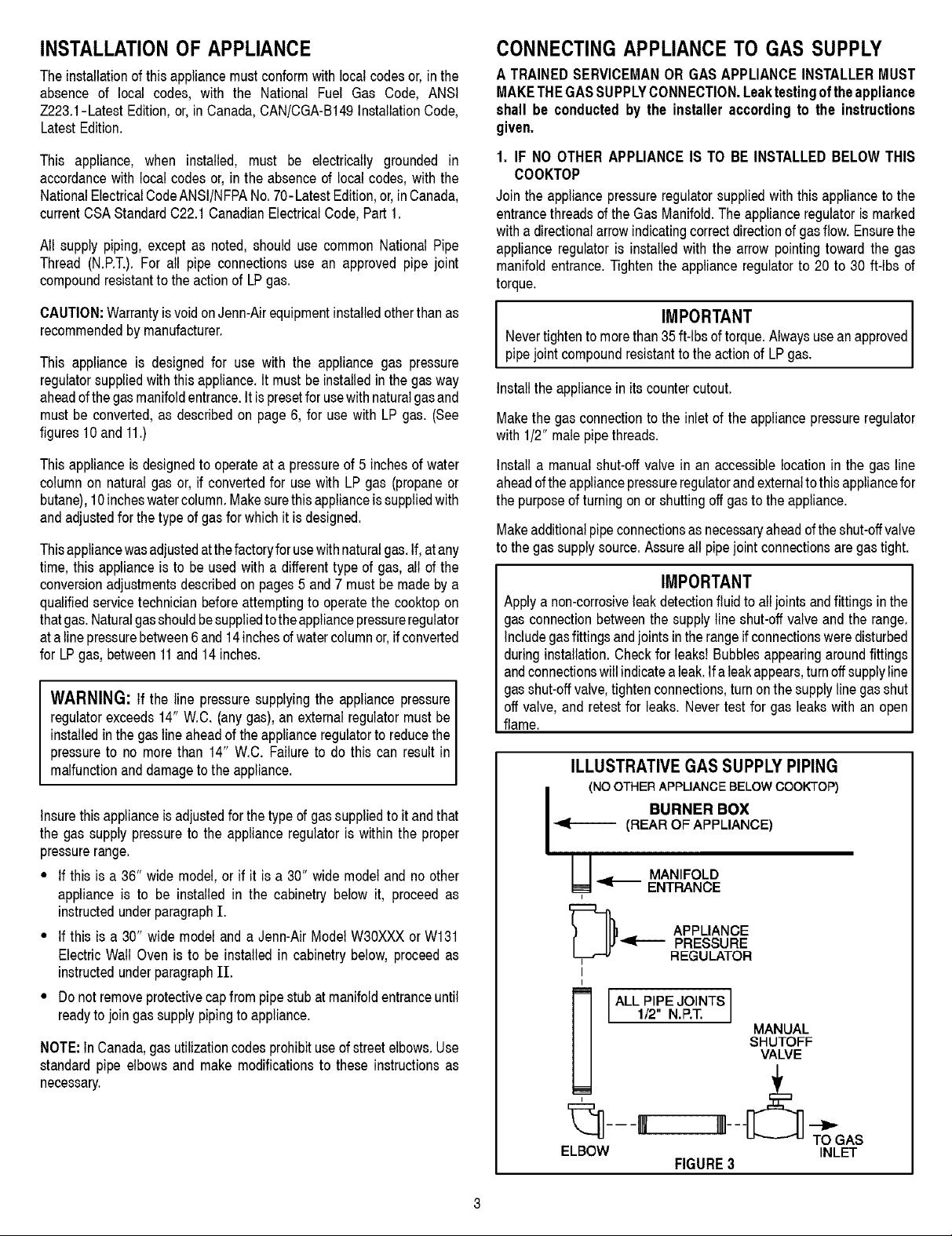
Join theappliancepressureregulatorsuppliedwiththis applianceto the
entrancethreadsof theGasManifold.Theapplianceregulatorismarked
with adirectionalarrowindicatingcorrectdirectionof gasflow.Ensurethe
applianceregulatoris installedwith the arrowpointingtoward the gas
manifoldentrance.Tightenthe applianceregulatorto 20 to 30 ft-tbs of
torque.
Nevertightento morethan35ft-lbsof torque.Alwaysusean
I IMPORTANT approved
pipejointcompoundresistantto the actionof LPgas.
Installthe appliancein itscountercutout.
Makethe gasconnectionto the inletof the appliancepressureregulator
with 1/2"malepipethreads.
This applianceis designedto operateat a pressureof 5 inchesofwater
columnon naturalgasor, if convertedfor usewith LPgas (propaneor
butane),10incheswatercolumn.Makesurethisapplianceis suppliedwith
andadjustedfor thetype ofgasforwhich itisdesigned.
Thisappliancewasadjustedatthefactoryforusewithnaturalgas.If,atany
time,this applianceis to be usedwitha differenttypeof gas,all of the
conversionadjustmentsdescribedon pages5 and7 mustbe madeby a
qualifiedservicetechnicianbeforeattemptingto operatethe cooktopon
thatgas.Naturalgasshouldbesuppliedtotheappliancepressureregulator
atalinepressurebetween6and14inchesofwatercolumnor,ifconverted
for LPgas,between11and 14inches.
WARNING: If the line pressuresupplyingthe appliancepressure
regulatorexceeds14"W.C. (anygas),anexternalregulatormustbe
installedinthegaslineaheadof theapplianceregulatorto reducetheI
pressureto no morethan 14" W.C. Failureto do this can resultin
mafunctonanddamagetothe app ance.
Insurethisapplianceisadjustedforthetypeof gassuppliedto itandthat
the gas supplypressureto the applianceregulatoris within the proper
pressurerange.
• Ifthis is a 36" wide model,or if it is a 30" wide modeland no other
applianceis to be installed in the cabinetrybelow it, proceedas
instructedunderparagraphI.
• Ifthis is a 30"wide modelanda Jenn-AirModelW30XXXorW131
ElectricWall Ovenis to be installedin cabinetrybelow,proceedas
instructedunderparagraph11.
• Donotremoveprotectivecapfrompipestubatmanifoldentranceuntil
readyto joingassupplypipingto appliance.
NOTE:In Canada,gasutilizationcodesprohibituseof streetelbows.Use
standardpipeelbowsand make modificationsto these instructionsas
necessary.
Installa manualshut-offvalvein an accessiblelocationin the gasline
aheadof theappliancepressureregulatorandexternaltothisappliancefor
the purposeofturningonor shuttingoffgastotheappliance.
Makeadditionalpipeconnectionsasnecessaryaheadoftheshut-offvalve
to thegas supplysource.Assureallpipejointconnectionsaregastight.
IMPORTANT
Applya non-corrosiveleakdetectionfluidto alljointsandfittingsinthe
gasconnectionbetweenthe supplylineshut-offvalveand the range.
Includegasfittingsandjointsintherangeifconnectionsweredisturbed
duringinstallation.Checkforleaks!Bubblesappearingaroundfittings
andconnectionswillindicatealeak.Ifaleakappears,turnoffsupplyline
gasshut-offvalve,tightenconnections,turnonthesupplylinegasshut
offvalve,and retestfor leaks.Nevertestfor gas leakswith an open
flame.
ILLUSTRATIVEGAS SUPPLYPIPING
BURNER BOX
i (NO OTHER APPLIANCE BELOW COOK'TOP)
(REAROF APPLIANCE)
U MANIFOLDENTRANCE
APPLIANCEPRESSURE
i REGULATOR
I
I
1/2 N.P.T.
ALL PIPEJOINTS
I
MANUAL
SHUTOFF
VALVE
!1---_ _
ELBOW
FIGURE3
TOGAS
INLET
Page 4

2. IFTHISISA 30"WIDE COOKTOPAND AJENN-AIR,MODEL
W30XXXORW131,ELECTRICWALLOVENISTOBE INSTALLED
BELOWTHISCOOKTOP.
NOTE1:Thisapplianceandits gasandelectricalsupplysourcesmustbe
installedbeforethe wallovenisinstalled.Seeillustration(ElectricalWiring
Information- page4;figure6)for recommendedelectricalsupplysource
locations.
NOTE2:Itmaybenecessarytoextendgassupplypipingforthisappliance
intoadjacentunder-countercabinetrywhen awallovenisinstalledbelow
thisappliance.
Joina 1/2" NPTpipeelbow(locallyavailable)to themalethreadsatthe
manifoldentrance.Whenjoined,causetheopenthreadsof the elbowto
facetowardtheleftsideoftheappliance.Installtheapplianceinitscounter
cutout.
Joina 1/2"NPTpipenippleto theelbowusinga pipesectionofsufficient
lengthto extend,horizontally,beyondthe left sideof the wall oven. (To
accomplishthisitmaybenecessaryto extendthepipesectionintoadjacent
cabinetry.)Join additional 1/2" NPT elbow(s) and pipe nipples, as
necessary,to accomplishthe following:
Join the outlet of the appliancepressureregulatorsuppliedwith this
applianceto the matethreadsof the newlyinstalledgassupplypiping.
Installtheapplianceregulatorina locationwhichwill beaccessiblebeside
or belowthewall oven.Insurethe applianceregulatorisinstalledwith its
directionalarrowpointinginthedirectionofgasflow.Tightentheappliance
regulatorto20to 30ft-tbsoftorque.
ILLUSTRATIVEGASSUPPLY PIPING
(WALLOVENINSTALLEDBELOW30" OOOKTOP)
/ BURNER BOX
.J _ (REAROF APPLIANCE)
MANIFOLD
f
PIPING PASSES THROUGH DIVIDING
• NIPPLES
(Lengths
I tosuit)
I I ALL PIPE JOINTS1/2 N.P.T.
I PRESSURE SHUTOFF
APPROXIMATE CROSS SECTION
_VALL BETWEEN ADJACENT CAB NETS
APPLIANCE MANUAL
REGULATOR VALVE
INLET
PROFILE OF WALL OVEN
FIGURE4
Nevertightento morethan35ft-tbsoftorque.Alwaysusean
pipejointcompoundresistantto theactionof LPgas.
IMPORTANT approved
Locateandjoinamanualshut-offvalveinanaccessiblelocationinthe gas
lineaheadoftheapplianceregulatorandexternalto theappliancefor the
purposeofturningonor shuttingoffgasto theappliance.
Makeadditionalpipeconnectionsasnecessaryaheadoftheshut-offvalve
tothegassupplysource.Assureallpipejointconnectionsaregastight.
IMPORTANT
Applya non-corrosiveleakdetectionfluidto all jointsandfittingsinthe
gasconnectionbetweenthesupply lineshut-offvalveandthe range.
Includegasfittingsandjointsintherangeif connectionsweredisturbed
duringinstallation.Checkforleaks!Bubblesappearingaroundfittings
andconnectionswiltindicatealeak.Ifaleakappears,turnoffsupplyline
gasshut-offvalve,tightenconnections,turnonthesupplylinegasshut
off valve,and retestfor leaks. Nevertest for gasleakswith an open
flame.
Note,regardingFigure4,above:
• Forconveniencein servicea groundjointunion (notshown: locally
available)shouldbeincludedin the pipingillustratedin figure4, ina
locationmostpracticalfortheinstallation.Generally,a practicallocation
isinthecabinetbelowthisappliance,nearthemanifoldentrance,rather
thaninanadjoiningcabinet.
• Ifthe alternativepipingmethodshownin figure5 is selectedfor the
installation,no groundjoint unionis required.(Theflexibleappliance
connectorillustratedprovidestheunionjointsnecessaryforservicing.)
Whena dividingwall is presentand a flexibleconnectoris usedit is
recommendedfor convenience,in both installationand service,the
flexibleconnector,itself, passthroughthe dividingwall. Any flexible
connectorusedwiththis appliancemustsatisfyall requirements
statedin the text accompanyingfigure 5.
Page 5

ALTERNATIVEPIPING METHODSTO CONNECT
APPLIANCETO GAS SUPPLY
A TRAINEDSERVICEMANOR GASAPPLIANCEINSTALLERMUST
MAKETHEGASSUPPLYCONNECTION.Leaktestingofthe appliance
shall be conductedby the installeraccordingto the instructions
given.
Unlessprohibitedbylocalcodesorordinances,a newA.G.A.- Certified,
flexiblemetalapplianceconnectormaybeusedto connectthisappliance
to itsgassupply.Theconnectormusthavean internaldiameternotless
thannominal1/2"NPTpipeandbenomorethan5feet inlength.A 1/2"
NPT x 1/2" flare union adapteris requiredat each end of the flexible
connector.If a flexibleconnectoris usedassurethat boththe appliance
pressureregulatorandmanualshut-offvalveare joined solidlyto other
permanenthardpiping(eithergassupplyortheappliancemanifold)soas
to bephysicallystationary.Seeillustrationsbelow:
ILLUSTRATIVEALTERNATIVEPIPING
CAUTION:Donotattemptto attachthe flexibleconnectordirectlyto an
externalpipethread.Connectionrequiresflareunionadapters.
IMPORTANT
Applya non-corrosiveleakdetectionfluidto alljointsandfittingsinthe
gasconnectionbetweenthe supplylineshut-offvalveand the range.
Includegasfittingsandjointsintherangeifconnectionsweredisturbed
duringinstallation.Checkforleaks!Bubblesappearingaroundfittings
andconnectionswillindicatealeak.Ifaleakappears,turnoffsupplyline
gasshut-offvalve,tightenconnections,turnonthesupplylinegasshut
offvalve,and retestfor leaks.Nevertestfor gas leakswith an open
flame.
PRESSURETESTING
The appliancemustbe isolatedfrom the gas supplypiping systemby
closingits individualmanualshut-offvalveduringanypressuretestingof
the gassupplypipingsystemattest pressuresequalto or lessthan1/2
PSIG(3.5kPa).
This appliance, as well as its individual shut-off valve, must be
disconnectedfrom the gas supply piping systemduring any pressure
testingofthesystemat testpressuresinexcessof1/2 PSIG(3.5kPa).
When checkingapplianceregulatorfunction,make certainpressureof
naturalgas supply is between6 and 14 inchesof water columnor, if
convertedfor LPgas,between11and 14inches.
I
_ -'<1- Rare
NO APPLIANCE
MOUNTED BELOW
THIS COOKTOP
WALL OVEN MOUNTED
IN CABINETRY BELOW
Union
Adaptor
I
Valve
!
.,_._ " Ngr Pipe
(Stationary
supplypips)
THIS COOKTOP
FIGURE5
I
I_ _=l-- Flare
Union
Adaptor
I
-,91--- ppliancePressu
Regulator,suppli_
(Observe
directionality
of6as Flow)
I
Nipple
I
Valve
I
1-- " NPTPipe
(Stationary
supplypipe)
Page 6

ELECTRICALWIRINGINFORMATION
Thisapplianceis equippedwithagroundedtypepowercord.Agrounded
outletmustbeprovided,ttisrecommended,forconvenience,theoutletbe
located(withreferencetofigure6)as inAorB,below:
A. Ifnootherapplianceisto beinstalledbelowthisappliance:withineither
theshadedareaorthe crosshatchedareashowninfigure6.
B. If a ModelW30XXXorW131 electricovenisto beinstalledbelowthis
appliance,either:
1. withinthecrosshatchedareaoffigure6, or,
2. withinanadjacentcabinet.
CABINET BO'i-rOM
FIGURE6
DimensionA:
W30XXX:5-1/2" (13.97cm)
W131:4" (10.16cm)
If awallovenisto beinstalledbelowthisapplianceandthecounterunit's
outletisto be mountedwithinthe crosshatchedareaoffigure6:
1. The cabinet'slower front panel, belowthe oven, must be made
removableforaccesstothe outlet.
2. A clearanceholefor the powercord's plug(1-1/4"(3.18cm) dia is
recommended)mustbeprovidedthroughtheoven'sfloorsupportshelf
and,ifnecessary,throughtheslatssupportingtheshelf.Theclearance
holeshouldbelocatedas nearas practicaltothe rearofthe shelfand
(iftheovenismodelW30XXX)asnearaspracticaltotheleftrearcorner.
3. WhenmodetW30XXXismountedbelowthisappliance,andifthepower
outletfor this applianceis to be locatedinthe crosshatchedarea of
figure 6, it is recommendedthe powercord be routed throughthe
externalverticalclearancechannelat the left rear of the oven.The
channel'scrosssectionisapproximately4.2" x 2.25" (10.7x5.7cm),
extendingthe full heightof the oven.(ModelW131providesasimilar,
butlarger,verticalchannelnearthecenterofthe mainbackoftheoven.)
If the outlet isto be mountedineither aleft or rightadjacentcabinet,a
clearancehole,asdescribedabove,mustbe providedinthedividingwall
betweenthe cabinets.Figure4; page 3, illustratesa typical (left side)
dividingwall.Theclearancehole(notshownin figure4)canbelocatedas
isconvenientinthisleftwall or inthecorrespondingrightwall.
In planningany installation,notethat the freelength of this appliance's
powercord,extendingbeyonda point3-3/4"(9.53cm)leftof thenominal
centerof therearwallof theburnerbox,whenviewedfromthe frontofthe
unit,isapproximately46" (117cm).
WARNING
ELECTRICALGROUNDING INSTRUCTIONS
THIS APPLIANCE IS EQUIPPED WITH A THREE PRONG
GROUNDINGPLUGFORYOUR PROTECTIONAGAINSTSHOCK
HAZARD AND SHOULD BE PLUGGED DIRECTLY INTO A
PROPERLY GROUNDED RECEPTACLE. DO NOT CUT OR
REMOVETHEGROUNDINGPRONGFROMTHISPLUG.
WARNING
THIS APPLIANCE MUST BE DISCONNECTED FROM ITSI
ELECTRICALSUPPLY AT THE WALL RECEPTACLEBEFORE
SERVC NGTHEAPPLANCE.
Page 7

CONVERTINGAPPLIANCE FOR USE
WITH LP GAS
WARNING
Propaneconversionistobe performedby aJENN-AIRAUTHORIZED
SERVICER (or other qualified agency) in accordance with the
manufacturer'sinstructionsand all codes and requirementsof the
authorityhavingjurisdiction.Failuretofollowinstructionscouldresultin
seriousinjuryor propertydamage,The qualifiedagencyperformingthis
workassumesresponsibilityforthisconversion.
WARNING
Electrical power and gas must be turned off prior to
conversion.
INSTALLATIONOF LP ORIFICESPUDS
4 BURNER MODEL (30"WIDE)
OO
This appliancewas adjustedat the factoryfor usewithnaturalgas.To
convertit forusewithLP gas(propaneor butane),eachof thefollowing
modificationsmustbeperformed:
A. Replaceallorificespuds
Step1: Removethegratesand burnerheads.
Step2: Removealuminumventuritube.
Step3: Trima smallpieceof maskingtapeto thesizeof a dimeand
affixit overthe endof a 5/16" nutdriver.
Step4: Firmlypressthenutdriverovertheorificespud(figure7)and
loosenspud byturningcounterclockwise.Carefully lift nut
driveroutofburnerthroat.Orificespudshouldbecapturedin
therecess.Repeatthisstepforeachburner.
REMOVALOF ORIFICESPUD
ALI_MH',IUM VENTURI _/_ 5,/16"NUT DRIVER
OO
FIGURE8
5 BURNER MODEL (36"WIDE)
©©©
O O
7" ICNITER
FIGURE7
Step5: LocatetheLPorificespudpackettapedtotheundersideofthe
burnerbox.Thespudshavesmall numbersstampedon the
side.This numbercodestheorifice diameterand its correct
burner location.Thefollowing illustrationsshow correctLP
orifice spud location for 4 burner and 5 burner models,
respectively.
A_T #9219 991-0
FIGURE9
Step6: With the maskingtapestill in placein the recessof the nut
driver,pressan LP orificespudinto the recesssothat it is
snuglycaptured.
Step7: Carefullyinstalltheorificespudintheappropriateburnerthroat
byturningclockwisetotighten.Tightentoatorqueof 15to20
inch-lbs,
Step8: Replacecylindricalaluminumventuritubes, Replaceburner
headsandgrates,Indexeachgratetoits burnerpan,
Step9: Savetheorificesremovedfromthe applianceforfutureuse.
Page 8

B. Invertcap inappliancepressureregulator
(Seefigures10and11.)
Withtheapplianceinstalled,theapplianceregulatorshouldbelocated
asshowninfigure3or4. Identifythetypeofapplianceregulatoronthe
unitandfollowtheinstructionsintheappropriateillustration.
CONVERSIONOF MAXITROL APPLIANCE
PRESSURE REGULATOR
APPLYDOWNWARD
FINGERPRESSURE
ATDISCEDGESTO
REPLACEPININ_1_
CONVERTER_ _ LP
_z,.A CAP I
NAT ! /-_'[_
NDPIN . J
.J
NAT IL_P
FINGERPRESSURE
APPLYSIDEWARD
FROMCAP
I_T0 REMOVEPIN
3. Inserta slender,thin-bladescrewdriverintotherecessatcenterof
valvestemandengagebladewithslot inadjustingscrew.
4. Turn centerstemadjustingscrewto setflamesize.
... clockwisetoreduce
... counterclockwiseto increase
5. Replacecontrolknobwhenadjustmentiscompleted.
Properadjustmentwill producea stable,steadyblueflame of minimum
size.Thefinaladjustmentshouldbecheckedbyturningknobfromhighto
lowseveraltimeswithoutextinguishingtheflame.
Thisadjustment,atlowsetting,willautomaticallyprovidetheproperflame
sizeat mediumsetting.
I
COUNTERCLOCKWISE
TO INCREASE FLAME
;IZE
CLOCKWISE
TO REDUCE
FLAME SIZE
1
FIGURE10
CONVERSIONOF HARPER-WYMAN APPLIANCE
PRESSURE REGULATOR
i
O
NaturalSetting
FIGURE11
C. LowFlameAdjustment
(Seefigure12.)
This applianceis shippedfromthefactorywith lowandmediumflame
settingsadjustedfor use with naturalgas. If furtheradjustmentis
necessary,orto readjustfor usewith LP,proceedas follows:
LPSetting
VALVE
STEM
FIGURE12
After ConversionStepsA, B and C have been completed,checkthe
appearanceof eachburner'sflameattheHiandLosettingsagainstfigure
13.Ifthe flamesappeartoo largeortoo small,revieweach stepto make
sureitwascompletedcorrectly.
FLAMEAPPEARANCE ATHIAND LO
Mad
LO_ HI
LO_ HI
Off
1. Lightburnerandsetcontrolknowfor lowflame.
2. Removecontrolknobfromvalvestem.
CAUTION:NEVERUSEA METALBLADETOPRYKNOBOFF.IF
KNOBCANNOTBEEASILYREMOVED,TUCKTHEFOLDSOFA
CLOTHDISHTOWELUNDERTHEKNOBANDPULLTHETOWEL
UPWARDWITHSTEADY,EVENPRESSURE.
Mad
LO_ HI
011
FIGURE13
Page 9

TO CONVERTAPPLIANCE FOR USE WITH
NATURALGAS
INSTALLATIONOF NATURALGAS
ORIFICESPUDS
WARNING
Electrical power and gas must be turnedoff prior to
conversion.
If this appliancehas been convertedfor use with LP gas, eachof the
following modificationsmust be performedto convertthe unit back to
naturalgas.
A. Replaceallorificespuds
PerformSteps 1through4on page5.
ForStep5:Locatethecoloredbrassnaturalgasorificespudsthatwere
originallyinstalledinthisappliancebeforeitsconversionfor usewithLP
gas.Observethecolorofeachofthespudsandnotethecorrectburner
locationfor eachspudasshowninfigures14and15.
CompleteSteps6through9 on page5 to completethe installationof
naturalgasmainspudsintheircorrectlocations.
Savethe orificesremovedfromthe applianceforfutureuse.Theywill
beneededifthis applianceisagainconvertedforusewithLPgas.
B. Invertcapin appliancepressureregulator.
(Seefigures10and11.)
With theapplianceinstalledtheapplianceregulatorshouldbelocated
as shownin eitherfigure 3 or figure 4 (page3). Identifythe type of
applianceregulatorand follow the instructionsin the appropriate
illustration.
4 BURNER MODEL (30"
OO
QO
FIGURE14
5 BURNER MODEL (36" WIDE)
C. Adjustlowflameas instructedon page6itemC.
AfterStepsA,BandChavebeencompleted,checktheappearanceof
eachburner'sflameat theHi andLosettingsagainstfigure13.tf the
flames appear too large or too small, make sure all steps were
completedcorrectly.
OO
O O
FIGURE15
)
Page 10

BURNERIGNITIONAND AUTO-REIGNITION
This applianceis equippedfor electronicauto-reignitionby meansof a
sparkigniterlocatedatthe rearofeachburner.The burnersaredesigned
tolightatanyvalverotationthatadmitssufficientgasflowtosupportaflame
andto automaticallyretightfollowingalossofflamedueto adraftorother
adversecondition.Thisfeatureisprovidedas a convenienceandis not
intendedas asafetyfeature.
CAUTION:Neverusea metalbladeto pryoff a controlknob.tf a knob
cannotbeeasilyremovedtuckthe folds of a clothdishtowelunderand
aroundtheknobandpullthe towelupwardwith steadyevenpressure.
CAUTION:Nevercovercontrolknobsorsurroundingcontrolsurfacewith
utensils,towels,orotherobjects.Neverobstructfreeairpassagepastthe
controlknobs.The knobopeningshavebeensizedto properlycontrolair
entrytotheinterioroftheapplianceduringoperation.
This appliance has no air shutters. Primary air adjustments are
unnecessary.Theburnersaredesignedtoprovideoptimumaerationforall
gases without air shutters. When operatingproperly,burners should
produceclearlydefined,evenblueflames.Iftheflameshaveyellowtipsor
arehazyandotherwiseappearto haveinsufficientair,obtaintheservices
ofa qualifiedservicetechnician.
Specifiedinputratesareasshowninfigures16and 17,below.
4 BURNER MODEL
TOP GRATEREPLACEMENT
Thetopgratesonthiscooktophaveundersideprojectionlugsdesignedto
nestin matchingdepressionsinthespillovertrays.Duringgrateplacement
alwayspositiongratestomakethisengagement.Correctindexingof grates
aboveburnerportswill preservethe grates'appearanceandhelpassure
longlife.
DETENT
WITH
INDENTATION
REQUIREDADJUSTMENTSAT TIME
OF INSTALLATION
Theinstallationofthis appliancemustconformwithlocalcodes,orinthe
absenceof localcodes,with the latesteditionof the NationalFuelGas
Code ANSI Z223.1 USA or currentCAN!CGA-B149INSTALLATION
CODE.
BURNER
LOCATION
RightFront
RightRear
LeftFront
LeftRear
BURNER
LOCATION
RightFront
RightRear
Center
LeftFront
LeftRear
FIGURE16
INPUTRATES- NATURALGAS(BTU/HR)
Hi Lo
12,000 1,500
9,100 1,050
6,500 830
10,500 1,500
5 BURNER MODEL
FIGURE17
INPUTRATES- NATURALGAS(BTU/HR)
Hi Lo
12,000 1,500
9,100 1,050
6,500 830
9,100 1,050
10,500 1,500
D Thisappliancewasmanufacturedfor usewithNaturalGas.If LPgas
isthefuelofchoice,followtheconversionto LPprocedurefoundinthe
installationinstructions.
D Testall externalconnectionsfor gasleaks.Nevertest forgas leaks
withanopenflame.
D Testallelectricalconnections.
10
 Loading...