

Page 1
GROUP TAB LOCATOR
Maintenance Schedules
0
Cooling - 2.5L / 2.8L Diesel
7
8E
8F
11
14
21
25
Service Manual Comment Forms (Rear of Manual)
Electronic Control Modules
Engine Systems
Ignition Control
8I
Engine
9
Exhaust System and Turbocharger
Fuel System
Automatic Transmission - 545RFE
Emissions Control - 2.5L / 2.8L Turbo Diesel
Page 2

KJ MAINTENANCE SCHEDULES 0 - 1
MAINTENANCE SCHEDULES
TABLE OF CONTENTS
page
MAINTENANCE SCHEDULES FOR ALL
MARKETS EXCEPT U.S., CANADA and
MEXICO
DESCRIPTION — DIESEL ENGINES .........1
MAINTENANCE SCHEDULES FOR ALL MARKETS EXCEPT U.S., CANADA and MEXICO
DESCRIPTION — DIESEL ENGINES
Maintenance Schedule Information not included in
this section, is located in the appropriate Owner’s
Manual.
There are two maintenance schedules that show
the required service for your vehicle.
First is Schedule “B”. It is for vehicles that are
operated under the conditions that are listed below
and at the beginning of the schedule.
• Extensive engine idling.
• Driving in dusty conditions.
• More than 50% of your driving is at sustained
high speeds during hot weather, above 32° C (90° F).
• Trailer towing.
• Taxi, police, or delivery service (commercial ser-
vice).
NOTE: Most vehicles are operated under the conditions listed for Schedule (B(.
Second is Schedule “A”. It is for vehicles that are
not operated under any of the conditions listed under
Schedule 9B9.
Use the schedule that best describes your driving
conditions. Where time and mileage are listed, follow
the interval that occurs first.
CAUTION: Failure to perform the required maintenance items may result in damage to the vehicle.
At Each Stop for Fuel
• Check the engine oil level about 5 minutes after
a fully warmed engine is shut off. Checking the oil
level while the vehicle is on level ground will
improve the accuracy of the oil level reading. Add oil
only when the level is at or below the ADD or MIN
mark.
• Check the windshield washer solvent and add if
required.
Once a Month
• Check the tire pressure and look for unusual
wear or damage.
• Inspect the battery and clean and tighten the
terminals as required.
• Check the fluid levels of coolant reservoir, brake
master cylinder, power steering and transmission
and add as needed.
• Check all lights and all other electrical items for
correct operation.
At Each Oil Change
• Change the engine oil filter.
• Inspect the exhaust system.
• Inspect the brake hoses.
• Check the manual transmission fluid level — if
equipped.
• Check the coolant level, hoses, and clamps.
• Inspect engine accessory drive belts. Replace as
necessary.
• Inspect for the presence of water in the fuel filter/water separator unit.
• Rotate the tires.
Schedule “B”
Follow schedule “B” if you usually operate your
vehicle under one or more of the following conditions.
• Extensive engine idling.
• Driving in dusty conditions.
• More than 50% of your driving is at sustained
high speeds during hot weather, above 32° C (90° F).
• Trailer towing.
• Taxi, police, or delivery service (commercial ser-
vice).
Page 3

0 - 2 MAINTENANCE SCHEDULES KJ
MAINTENANCE SCHEDULES FOR ALL MARKETS EXCEPT U.S., CANADA and MEXICO (Continued)
Kilometers 10 000 km 20 000 km 30 000 km 40 000 km 50 000 km
Change the engine oil and engine oil filter. XXXXX
Inspect the ball joints. XXXXX
Inspect engine accessory drive belt. XXXX
Replace engine accessory drive belt. X
Inspect the engine air filter element.
Replace as necessary.
Replace the engine air filter element. X X
Replace the engine timing belt. X
Inspect idler pulleys and timing belt
tensioner‡.
Replace fuel filter/water separator unit. X X
Inspect the brake linings. XXXXX
Drain and refill the front and rear axle fluid. X X
Drain and refill automatic transmission fluid
and replace transmission main sump filter.
XXX
X
X
Kilometers 60 000 km 70 000 km 80 000 km 90 000 km 100 000 km
Change the engine oil and engine oil filter. XXXX X
Inspect the ball joints. XXXX X
Inspect engine accessory drive belt. XXXX X
Replace engine accessory drive belt. X
Inspect the engine air filter element.
Replace as necessary.
Replace the engine air filter element. X X X
Inspect idler pulleys and timing belt
tensioner‡.
Replace the engine timing belt. X
Inspect the brake linings. XXXX X
Drain and refill the front and rear axle fluid. X X X
Replace the fuel filter/water separator unit. X X X
Drain and refill the transfer case fluid. X
Drain and refill the automatic transmission
fluid and replace transmission main sump
filter.
XX
X
X
Page 4

KJ MAINTENANCE SCHEDULES 0 - 3
MAINTENANCE SCHEDULES FOR ALL MARKETS EXCEPT U.S., CANADA and MEXICO (Continued)
Kilometers 110 000 km 120 000 km 130 000 km 140 000 km 150 000 km 160 000 km
Change the engine oil and
engine oil filter.
Inspect the ball joints. XXXXXX
Inspect the engine air filter
element. Replace as
necessary.
Replace the engine air filter
element.
Inspect engine accessory
drive belt.
Replace engine accessory
drive belt.
Inspect the idler pulleys and
timing belt tensioner‡.
Replace the engine timing
belt.
Inspect the brake linings. XXXXXX
Drain and refill the front and
rear axle fluid.
Replace the fuel filter/water
separator unit.
Flush and replace the engine
coolant.
Drain and refill automatic
transmission fluid and replace
transmission filter (s).
XXXXXX
XXX
XXX
XXXX X
X
X
X
XXX
XXX
X
X
Inspection and service should also be performed
anytime a malfunction is observed or suspected.
Retain all receipts.
‡ Replace if there is superficial wear, bearing clearance, or evident grease leak.
Page 5

0 - 4 MAINTENANCE SCHEDULES KJ
MAINTENANCE SCHEDULES FOR ALL MARKETS EXCEPT U.S., CANADA and MEXICO (Continued)
Schedule “A”
Kilometers 20 000 km 40 000 km 60 000 km 80 000 km 100 000 km
Change the engine oil and engine oil
filter.
Inspect the ball joints. XXXXX
Inspect the brake linings. X X
Inspect the engine air filter element.
Replace as necessary.
Replace the engine air filter element. X X
Inspect the engine accessory drive belt. XXXXX
Replace the engine accessory drive
belt.
Replace the fuel filter/water separator
unit.
Inspect idler pulleys, and timing belt
tensioner‡.
Replace the engine timing belt. X
Inspect the transfer case fluid. X
XXXXX
XXX
X
XXXXX
X
Kilometers 120 000 km 140 000 km 160 000 km 180 000 km
Change the engine oil and engine oil filter. X X X X
Inspect the ball joints. X X X X
Inspect the brake linings. X X
Inspect the engine accessory drive belt. X X X X
Inspect the engine air filter element. Replace
as necessary.
Replace the engine air filter element. X X
Replace the fuel filter/water separator unit. X X X X
Flush and replace the engine coolant. X
Inspect the transfer case fluid. X
Drain and refill the transfer case fluid. X
Drain and refill automatic transmission fluid
and replace transmission filter (s).
Inspection and service should also be performed
anytime a malfunction is observed or suspected.
Retain all receipts.
‡ Replace if there is superficial wear, bearing clearance, or evident grease leak.
WARNING: You can be badly injured working on or
around a motor vehicle. Do only that service work
for which you have the knowledge and the right
equipment. If you have any doubt about your ability
to perform a service job, take your vehicle to a
competent mechanic.
XX
X
Page 6

KJ COOLING - 2.5L/2.8L TURBO DIESEL 7 - 1
COOLING - 2.5L/2.8L TURBO DIESEL
TABLE OF CONTENTS
page page
COOLING - 2.5L/2.8L TURBO DIESEL
DESCRIPTION - COOLING SYSTEM .........1
DIAGNOSIS AND TESTING
DIAGNOSIS AND TESTING - COOLING
SYSTEM FLOW CHECK .................1
DIAGNOSIS AND TESTING - COOLING
SYSTEM AERATION ....................1
DIAGNOSIS AND TESTING - COOLING
SYSTEM LEAK TEST....................2
DIAGNOSIS AND TESTING - ON-BOARD
DIAGNOSTICS (OBD) ...................2
DIAGNOSIS AND TESTING - COOLING
SYSTEM .............................3
COOLING - 2.5L/2.8L TURBO
DIESEL
DESCRIPTION - COOLING SYSTEM
The cooling system regulates engine operating temperature. It allows the engine to reach normal operating temperature as quickly as possible, maintains
normal operating temperature and prevents overheating.
The cooling system also provides a means of heating the passenger compartment. The cooling system
is pressurized and uses a centrifugal water pump to
circulate coolant throughout the system. A separate
and remotely mounted, pressurized coolant tank
using a pressure/vent cap is used.
COOLING SYSTEM COMPONENTS
The cooling system consists of:
• Charge Air Cooler
• Electric Cooling Fans
• A aluminum-core radiator with plastic side
tanks
• A separate pressurized coolant tank
• A pressure/vent cap on the coolant tank
• Fan shroud
• Thermostat
• Coolant
• Low coolant warning lamp
• Coolant temperature gauge
• Water pump
• Hoses and hose clamps
STANDARD PROCEDURE - COOLING
SYSTEM - REVERSE FLUSHING ...........7
CLEANING .............................8
INSPECTION ...........................8
SPECIFICATIONS
SPECIFICATIONS - COOLING SYSTEM
CAPACITY ............................8
SPECIFICATIONS - TORQUE .............8
ACCESSORY DRIVE .......................9
ENGINE ...............................16
DIAGNOSIS AND TESTING
DIAGNOSIS AND TESTING - COOLING SYSTEM FLOW CHECK
To determine whether coolant is flowing through
the cooling system, use the following procedures:
(1) If engine is cold, idle engine until normal operating temperature is reached. Then feel the upper
radiator hose. If it is hot, coolant is circulating.
WARNING: DO NOT REMOVE THE COOLING SYSTEM PRESSURE CAP WITH THE SYSTEM HOT AND
UNDER PRESSURE BECAUSE SERIOUS BURNS
FROM COOLANT CAN OCCUR.
(2) Remove pressure/vent cap when engine is cold,
idle engine until thermostat opens, you should
observe coolant flow while looking down in the coolant recovery pressure container. Once flow is
detected install the pressure/vent cap.
DIAGNOSIS AND TESTING - COOLING SYSTEM AERATION
Low coolant level in a cross flow radiator will
equalize in both tanks with engine off. With engine
at running and at operating temperature, the high
pressure inlet tank runs full and the low pressure
outlet tank drops, resulting in cooling system aeration. Aeration will draw air into the water pump
resulting in the following:
• High reading shown on the temperature gauge.
• Loss of coolant flow through the heater core.
• Corrosion in the cooling system.
Page 7
7 - 2 COOLING - 2.5L/2.8L TURBO DIESEL KJ
COOLING - 2.5L/2.8L TURBO DIESEL (Continued)
• Water pump seal may run dry, increasing the
risk of premature seal failure.
• Combustion gas leaks into the coolant can also
cause aeration.
DIAGNOSIS AND TESTING - COOLING SYSTEM LEAK TEST
WARNING: THE WARNING WORDS “DO NOT OPEN
HOT” ON THE RADIATOR PRESSURE CAP IS A
SAFETY PRECAUTION. WHEN HOT, PRESSURE
BUILDS UP IN COOLING SYSTEM. TO PREVENT
SCALDING OR INJURY, THE RADIATOR CAP
SHOULD NOT BE REMOVED WHILE THE SYSTEM
IS HOT OR UNDER PRESSURE.
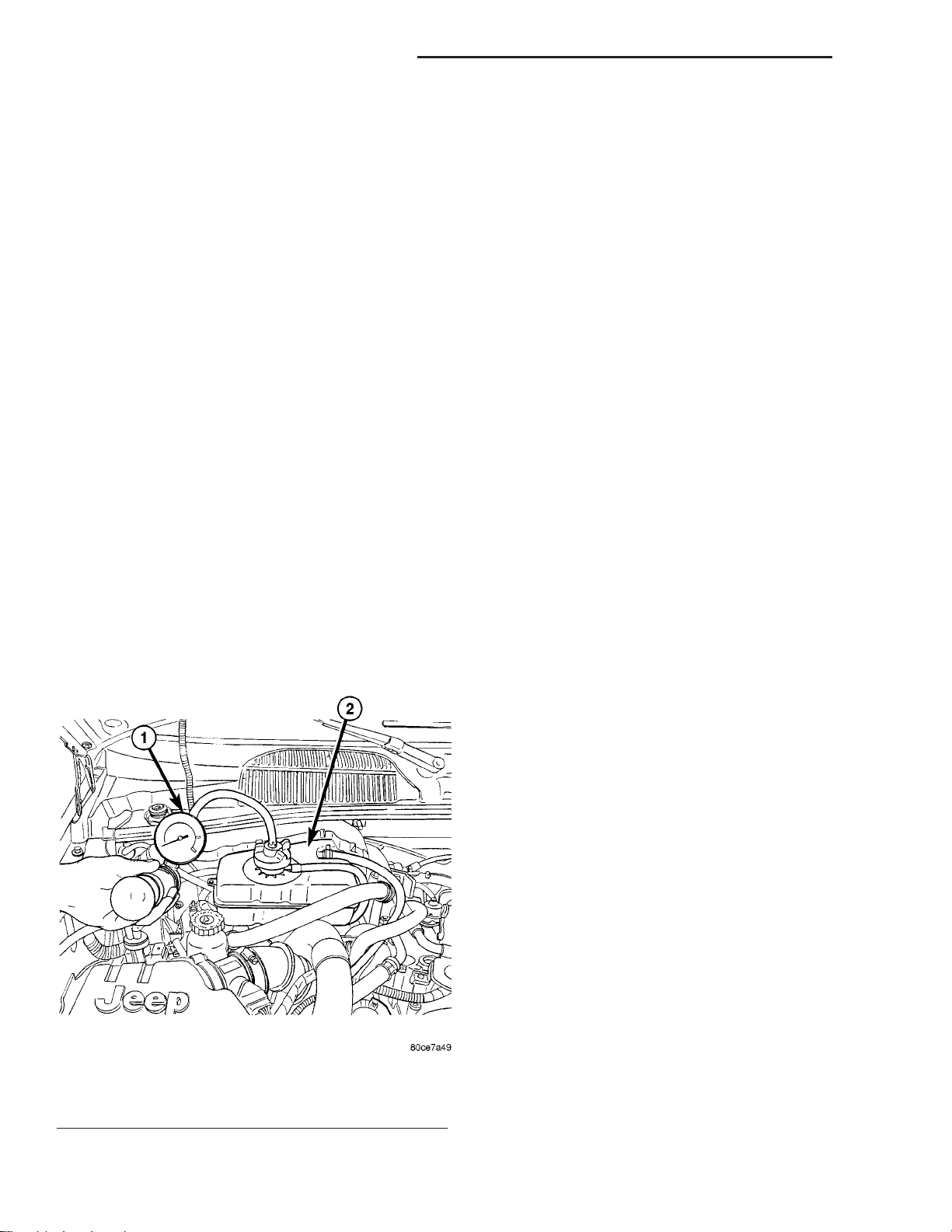
With engine not running, remove pressure/vent cap
from the coolant recovery pressure container and
wipe the filler neck sealing seat clean. The coolant
level in the recovery pressure container should be
full.
Attach the Cooling System Tester 7700 or equivalent to the radiator, as shown in (Fig. 1) and apply
104 kPa (15 psi) pressure. If the pressure drops more
than 13.8 kPa (2 psi) in 2 minutes, inspect all points
for external leaks.
All radiator and heater hoses should be shaken
while at 104 kPa (15 psi), since some leaks occur only
while driving due to engine movement.
If there are no external leaks, after the gauge dial
shows a drop in pressure, detach the tester. Start
engine and run until the thermostat opens, allowing
the coolant to expand. Reattach the cooling system
tester. If the needle on the dial fluctuates it indicates
a combustion leak, usually a head gasket leak.
WARNING: WITH TOOL IN PLACE, PRESSURE WILL
BUILD UP RAPIDLY. EXCESSIVE PRESSURE BUILT
UP, BY CONTINUOUS ENGINE OPERATION, MUST
BE RELEASED TO A SAFE PRESSURE POINT.
NEVER PERMIT PRESSURE TO EXCEED 138 kPa
(20 psi).
If the needle on the dial does not fluctuate, raise
the engine rpm a few times. If an abnormal amount
of coolant or steam emits from the tailpipe, it may
indicate a coolant leak caused by a faulty head gasket, cracked engine block, or cracked cylinder head.
There may be internal leaks that can be determined by removing the oil dipstick. If water globules
appear intermixed with the oil it will indicate an
internal leak in the engine. If there is an internal
leak, the engine must be disassembled for repair.
DIAGNOSIS AND TESTING - ON-BOARD DIAGNOSTICS (OBD)
COOLING SYSTEM RELATED DIAGNOSTICS
The Engine Control Module (ECM) has been programmed to monitor certain cooling system components. If the problem is sensed in a monitored circuit
often enough to indicated an actual problem, a DTC
is stored. The DTC will be stored in the ECM memory for eventual display to the service technician.
(Refer to 25 - EMISSIONS CONTROL - DESCRIPTION).
Fig. 1 PRESSURE TESTING COOLING SYSTEM
1 - COOLANT PRESSURE TESTER
2 - COOLANT RECOVERY PRESSURE CONTAINER
ACCESSING DIAGNOSTIC TROUBLE CODES
To read DTC’s and to obtain cooling system data,
(Refer to 25 - EMISSIONS CONTROL - DESCRIPTION).
ERASING TROUBLE CODES
After the problem has been repaired, use the
DRBIIIt scan tool to erase a DTC. Refer to the
appropriate Powertrain Diagnostic Procedures service information for operation of the DRBIIIt scan
tool.
Page 8
KJ COOLING - 2.5L/2.8L TURBO DIESEL 7 - 3
COOLING - 2.5L/2.8L TURBO DIESEL (Continued)
DIAGNOSIS AND TESTING - COOLING SYSTEM
Establish what driving conditions caused the complaint. Abnormal loads on the cooling system such as
the following may be the cause:
(1) PROLONGED IDLE, VERY HIGH AMBIENT
TEMPERATURE, SLIGHT TAIL WIND AT IDLE,
SLOW TRAFFIC, TRAFFIC JAMS, HIGH SPEED
OR STEEP GRADES.
• Idle with A/C off when temperature gauge is at
end of normal range.
(2) TRAILER TOWING:
Consult Trailer Towing section of owners manual.
Do not exceed limits.
(3) RECENT SERVICE OR ACCIDENT REPAIR:
Determine if any recent service has been performed on vehicle that may effect cooling system.
This may be:
COOLING SYSTEM DIAGNOSIS-DIESEL ENGINE
CONDITION POSSIBLE CAUSES CORRECTION
TEMPERATURE GAUGE
READS LOW
1. Diesel engines, due to their
inherent efficiency are slower to
warm up than gasoline powered
engines, and will operate at lower
temperatures when the vehicle is
unloaded.
2. Is the temperature gauge
connected to the temperature gauge
coolant sensor on the engine?
3. Is the temperature gauge
operating OK?
4. Coolant level low in cold ambient
temperatures accompanied with poor
heater performance.
5. Improper operation of internal
heater doors or heater controls.
• Engine adjustments (incorrect timing)
• Slipping engine accessory drive belt
• Brakes (possibly dragging)
• Changed parts (incorrect water pump)
• Reconditioned radiator or cooling system refill-
ing (possibly under filled or air trapped in system).
NOTE: If investigation reveals none of the previous
items as a cause for an engine overheating complaint, refer to following Cooling System Diagnosis
charts.
These charts are to be used as a quick-reference
only.
1. The low gauge reading may be
normal. Refer to thermostats in the
manual text for information. See
Thermostat Diagnosis-Diesel
Engine.
2. Check, the engine temperature
sensor connector in the engine
compartment.
3. Check gauge operation. Repair
as necessary.
4. Check coolant level in the
coolant tank. Inspect system for
leaks. Repair leaks as necessary.
Refer to the Coolant section for
WARNINGS and precautions
before removing the pressure cap.
5. Inspect heater and repair as
necessary. Refer to Heating and
Air Conditioning for procedures.
Page 9
7 - 4 COOLING - 2.5L/2.8L TURBO DIESEL KJ
COOLING - 2.5L/2.8L TURBO DIESEL (Continued)
CONDITION POSSIBLE CAUSES CORRECTION
TEMPERATURE GAUGE
READS HIGH. COOLANT
MAY OR MAY NOT BE LOST
OR LEAKING FROM
COOLING SYSTEM
1. Trailer is being towed, a steep hill
is being climbed, vehicle is operated
in slow moving traffic, or engine is
being idled with very high ambient
(outside) temperature and the air
conditioning is on. Higher altitudes
could aggravate these conditions.
2. Temperature gauge reading
incorrectly.
3. Coolant low in coolant tank and
radiator.
4. Pressure cap not installed tightly. If
cap is loose, boiling point of coolant
will be lowered.
5. Poor seals at pressure/vent cap. 5. (a) Check condition of cap and
6. Freeze point of antifreeze not
correct. Mixture may be too rich.
7. Coolant not flowing through
system.
8. Radiator or A/C condenser fins are
dirty or clogged.
9. Radiator core is corroded or
plugged.
10. Aftermarket A/C installed without
proper A/C condenser.
11. Dragging Brakes. 11. Check and correct as
12. Non-factory bug screen is being
used reducing air flow.
13. Thermostat partially or completely
shut. This is more prevalent on high
mileage vehicles.
14. Cylinder head gasket leaking. 14. Check cylinder head gasket for
15. Heater core leaking. 15. Check heater core for leaks.
1. This may be a temporary
condition and repair is not
necessary. Turn off the air
conditioning and attempt to drive
the vehicle without any of the
previous conditions. Observe the
temperature gauge. The gauge
should return to the normal range.
If the gauge does not return to
normal range, determine the
cause for the overheating and
repair.
2. Check gauge. Refer to I/P
group.
3. Check for coolant leaks and
repair as necessary.
4. Tighten cap.
cap seals. (b) Check condition of
coolant tank filler neck. Make sure
it does not leak pressure.
6. Check antifreeze. Adjust
antifreeze-to-water ratio as
required.
7. Check for coolant flow in
coolant tank with engine warm and
thermostat open. Coolant should
be observed flowing through the
tank. If flow is not observed,
determine reason for lack of flow
and repair as necessary.
8. Clean debris from radiator or
A/C condenser
9. Have radiator re-cored or
replaced.
10. Install proper A/C condenser.
necessary.
12. Only a factory screen should
be used.
13. Check thermostat and replace
if necessary.
leaks.
Repair as necessary.
Page 10

KJ COOLING - 2.5L/2.8L TURBO DIESEL 7 - 5
COOLING - 2.5L/2.8L TURBO DIESEL (Continued)
CONDITION POSSIBLE CAUSES CORRECTION
TEMPERATURE GAUGE
READING IS INCONSISTENT
(FLUCTUATES, CYCLES OR
IS ERRATIC)
1. During cold weather operation,
with the heater blower in the high
position, the gauge reading may drop
slightly. Fluctuation is also influenced
by loads, outside temperature and
extended idle time with diesel
engines.
2. Temperature gauge or engine
mounted gauge sensor defective or
shorted. Also, corroded or loose
wiring in this circuit.
3. Gauge reading rises when vehicle
is brought to a stop after heavy use
(engine still running).
4. Gauge reading high after starting a
warm-up (hot) engine.
5. Coolant level low in the coolant
tank (air will build up in the cooling
system causing the thermostat to
open late).
6. Cylinder head gasket leaking
allowing exhaust gases to enter the
cooling system causing the
thermostat to open late.
7. Water pump impeller loose on
shaft.
8. Loose accessory drive belt (water
pump slipping).
9. Air leak on the suction side of the
water pump allowing air to build up in
the cooling system causing the
thermostat to open late.
1. A normal condition. No
correction is necessary.
2. Check operation of gauge and
repair as necessary.
3. A normal condition. No
correction needed. Gauge should
return to normal range after
vehicle is driven.
4. A normal condition. No
correction needed. Gauge should
return to normal after a few
minutes of engine operation.
5. Check and correct coolant
leaks.
6. (a) Check for cylinder head
gasket leaks with a commercially
available leak tester. (b) Check for
coolant in engine oil. Inspect for
white steam emitting from exhaust
system. Repair as necessary.
7. Check water pump and replace
as necessary.
8. Check and correct as
necessary.
9. Locate leak and repair as
necessary.
PRESSURE CAP IS
BLOWING OFF STEAM
AND/OR COOLANT.
TEMPERATURE GAUGE
READING MAY BE ABOVE
NORMAL BUT NOT HIGH.
COOLANT LEVEL MAY BE
HIGH IN COOLANT TANK
COOLANT LOSS TO THE
GROUND WITHOUT
PRESSURE CAP BLOWOFF.
GAUGE IS READING HIGH
OR HOT
1. Pressure relief valve in pressure/
vent cap is defective.
2. Head gasket leak or cracked
cylinder head.
1. Coolant leaks in radiator, cooling
system hoses, water pump, or
engine.
1. Check condition of pressure/
vent cap and cap seals.
2. Repair as necessary.
1. Pressure test cooling system
and repair as necessary.
Page 11

7 - 6 COOLING - 2.5L/2.8L TURBO DIESEL KJ
COOLING - 2.5L/2.8L TURBO DIESEL (Continued)
CONDITION POSSIBLE CAUSES CORRECTION
HOSE OR HOSES
COLLAPSE WHEN ENGINE
IS COOLING
NOISY FAN 1. Cooling fan blades loose. 1. Replace cooling fan assembly.
INADEQUATE AIR
CONDITIONER
PERFORMANCE (COOLING
SYSTEM SUSPECTED)
1. Vacuum created in cooling system
on engine cool-down is not being
relieved through pressure/vent cap.
2. Cooling fan blades striking a
surrounding object.
3. Air obstructions at radiator or A/C
condenser.
1. Radiator and/or A/C condenser is
restricted, obstructed or dirty (insects,
leaves, etc.)
2. Engine is overheating (heat may
be transferred from radiator to A/C
condenser. High Under hood
temperatures due to engine
overheating may also transfer heat to
A/C condenser).
3. The cooling system is equipped
with air seals at the radiator and/or
A/C condenser. If these seals are
missing or damaged, not enough air
flow will be pulled through the
radiator and A/C condenser.
1. Cap relief valve stuck. Replace
if necessary.
2. Locate point of fan blade
contact and repair as necessary.
3. Remove obstructions or clean
debris from radiator or A/C
condenser.
1. Remove restriction or clean
debris from radiator or A/C
condenser.
2. Correct overheating condition.
3. Check for missing or damaged
air seals. Repair as necessary.
INADEQUATE HEATER
PERFORMANCE. MAY BE
ACCOMPANIED BY LOW
GAUGE READING
1. Diesel engines, due to their
inherent efficiency are slower to
warm up than gasoline powered
engines, and will operate at lower
temperatures when the vehicle is
unloaded.
2. Coolant level low. 2. Pressure test cooling system.
3. Obstruction in heater hose fitting at
engine.
4. Heater hose kinked. 4. Locate kinked area. Repair as
5. Water pump is not pumping water
to heater core. When the engine is
fully warmed up, both heater hoses
should be hot to the touch. If only
one of the hoses is hot the water
pump may not be operating correctly.
The accessory drive belt may also be
slipping causing poor water pump
operation.
1. The lower gauge reading may
be normal.
Repair leaks as necessary.
3. Remove heater hoses and
check for obstructions. Repair as
necessary.
necessary.
5. Refer to water pumps in this
group. Repair as necessary. If a
slipping belt is detected, refer to
Engine Accessory Drive Belts in
this group. Repair as necessary.
Page 12

KJ COOLING - 2.5L/2.8L TURBO DIESEL 7 - 7
COOLING - 2.5L/2.8L TURBO DIESEL (Continued)
CONDITION POSSIBLE CAUSES CORRECTION
HEAT ODOR 1. Various heat shields are used at
certain drive line components. One or
more of these shields may be
missing.
2. Is temperature gauge reading
above the normal range?
3. Is the Cooling fan operating
correctly?
4. Has undercoating been applied to
any unnecessary components?
STEAM IS COMING FROM
FRONT OF VEHICLE NEAR
GRILL AREA WHEN
WEATHER IS WET, ENGINE
IS WARMED UP AND
RUNNING, AND VEHICLE IS
STATIONARY.
TEMPERATURE GAUGE IS
IN NORMAL RANGE
COOLANT ODOR 1. Coolant color is not necessarily an
1. During wet weather, moisture
(snow, ice, or rain condensation) on
the radiator will evaporate when the
thermostat opens. This opening
allows heated water into the radiator.
When the moisture contacts the hot
radiator, steam may be emitted. This
usually occurs in cold weather with
no fan or air flow to blow it away.
indication of adequate corrosion or
temperature protection. Do not rely
on coolant color for determining
condition of coolant.
1. Locate missing shields. Repair
or replace as necessary.
2. Refer to the previous
Temperature Gauge Reads High in
these Diagnostic Charts. Repair as
necessary.
3. Refer to Cooling System Fan in
this group for diagnosis. Repair as
necessary.
4. Clean undercoating as
necessary.
1. Occasional steam emitting from
this area is normal. No repair is
necessary.
1. Refer to Coolant in this group
for antifreeze tests. Adjust
antifreeze-to-water ratio as
necessary.
COOLANT LEVEL CHANGES
IN COOLANT TANK.
TEMPERATURE GAUGE IS
IN NORMAL RANGE
1. Level changes are to be expected
as coolant volume fluctuates with
engine temperature. If the level in the
tank was between the HOT and
COLD marks at normal engine
operating temperature, the level
should return to within that range
after operation at elevated
temperatures.
STANDARD PROCEDURE - COOLING SYSTEM REVERSE FLUSHING
CAUTION: The cooling system normally operates at
97-to-110 kPa (14-to -16 psi) pressure. Exceeding
this pressure may damage the radiator or hoses.
Reverse flushing of the cooling system is the forcing of water through the cooling system. This is done
using air pressure in the opposite direction of normal
coolant flow. It is usually only necessary with very
dirty systems with evidence of partial plugging.
1. This a normal condition. No
repair necessary.
CHEMICAL CLEANING
If visual inspection indicates the formation of
sludge or scaly deposits, use a radiator cleaner
(Mopar Radiator Kleen or equivalent) before flushing.
This will soften scale and other deposits and aid the
flushing operation.
CAUTION: Be sure instructions on the container are
followed.
REVERSE FLUSHING RADIATOR
Disconnect the radiator hoses from the radiator fittings. Attach a section of radiator hose to the radiator bottom outlet fitting and insert the flushing gun.
Connect a water supply hose and air supply hose to
the flushing gun.
Page 13
7 - 8 COOLING - 2.5L/2.8L TURBO DIESEL KJ
COOLING - 2.5L/2.8L TURBO DIESEL (Continued)
CAUTION: The cooling system normally operates at
97-to-110 kPa (14- to-16 psi) pressure. Exceeding
this pressure may damage the radiator or hoses.
Allow the radiator to fill with water. When radiator
is filled, apply air in short blasts allowing radiator to
refill between blasts. Continue this reverse flushing
until clean water flows out through rear of radiator
cooling tube passages. For more information, refer to
operating instructions supplied with flushing equipment. Have radiator cleaned more extensively by a
radiator repair shop.
REVERSE FLUSHING ENGINE
Drain the cooling system (Refer to 7 - COOLING STANDARD PROCEDURE). Disconnect the radiator
upper hose from the radiator and attach the flushing
gun to the hose. Disconnect the radiator lower hose
from the water pump. Attach a lead away hose to the
water pump inlet fitting.
CAUTION: Be sure that the heater control valve is
closed (heat off). This is done to prevent coolant
flow with scale and other deposits from entering
the heater core.
Connect the water supply hose and air supply hose
to the flushing gun. Allow the engine to fill with
water. When the engine is filled, apply air in short
blasts, allowing the system to fill between air blasts.
Continue until clean water flows through the lead
away hose. For more information, refer to operating
instructions supplied with flushing equipment.
Remove the lead away hose, flushing gun, water
supply hose and air supply hose. Remove the thermostat housing (Refer to 7 - COOLING/ENGINE/ENGINE COOLANT THERMOSTAT - REMOVAL).
Install the thermostat and housing with a replace-
ment gasket (Refer to 7 - COOLING/ENGINE/ENGINE COOLANT THERMOSTAT INSTALLATION). Connect the radiator hoses. Refill
the cooling system with the correct antifreeze/water
mixture (Refer to 7 - COOLING - STANDARD PROCEDURE).
CLEANING
Drain cooling system and refill with clean water.
Refer to procedures in this section. Run engine with
pressure/vent cap installed until upper radiator hose
is hot. Stop engine and drain water from system. If
water is dirty; fill, run, and drain system again, until
water runs clear.
INSPECTION
After performing a cleaning/flush procedure,
inspect all hoses, clamps and connections for deterioration and leaks. Inspect radiator and heater core for
leaks.
SPECIFICATIONS
SPECIFICATIONS - COOLING SYSTEM CAPACITY
SPECIFICATIONS
DESCRIPTION SPECIFICATION
Cooling System With
Auxiliary Heater
Cooling System With Out
Auxiliary Heater
16.6 Liters (17.5 qts.)
13.8 Liters (14.6 qts.)
SPECIFICATIONS - TORQUE
2.5L/2.8L DIESEL - TORQUE SPECIFICATIONS
DESCRIPTION N·m Ft. Lbs. In. Lbs.
Accessory Drive Belt Idler
Bolt
Accessory Drive Belt
Tensioner Bolt
Cooling Fan Support Bolts 47.1 35 —
Thermostat Housing Bolts 27.5 21 —
Water Pump Housing Nuts 24.4 18 215
53 39 —
47.1 35 —
Page 14
KJ ACCESSORY DRIVE 7 - 9
ACCESSORY DRIVE
TABLE OF CONTENTS
page page
ACCESSORY DRIVE
SPECIFICATIONS - ACCESSORY BELT
TENSION .............................9
BELT TENSIONERS
DESCRIPTION ..........................9
OPERATION ............................9
REMOVAL .............................10
INSTALLATION .........................10
DRIVE BELT
DESCRIPTION .........................11
ACCESSORY DRIVE
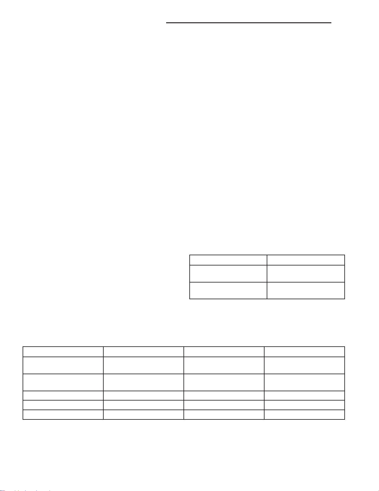
SPECIFICATIONS - ACCESSORY BELT TENSION
ACCESSORY DRIVE
BELT
2.5L/2.8L DIESEL ENGINE
A/C Compressor/
Generator
Power Steering Belt Dynamic Tensioner
GAUGE
Dynamic Tensioner
OPERATION-ACCESSORY DRIVE BELT ......11
DIAGNOSIS AND TESTING - ACCESSORY
DRIVE BELT .........................11
REMOVAL .............................13
INSTALLATION .........................13
IDLER PULLEYS
REMOVAL .............................14
INSTALLATION .........................15
BELT TENSIONERS
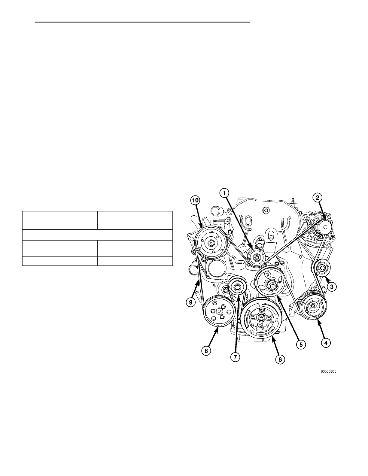
DESCRIPTION
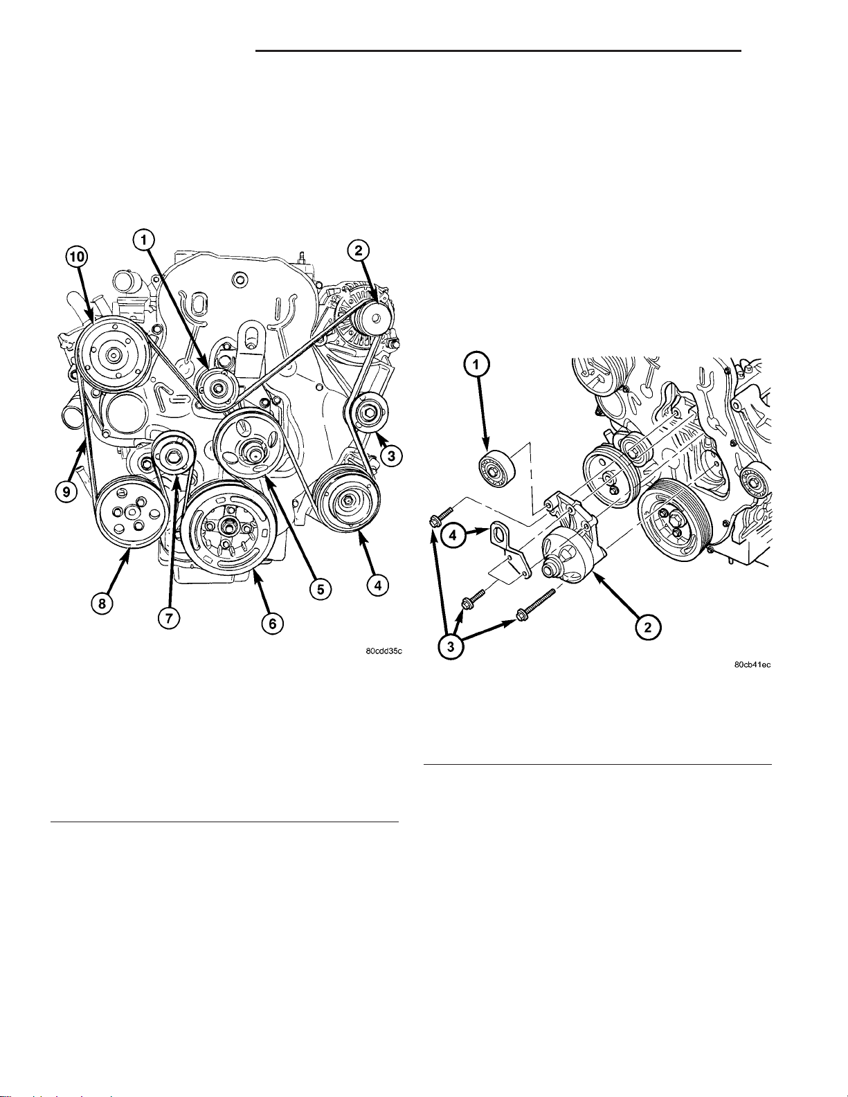
This engine is equipped with a spring loaded automatic belt tensioner (Fig. 1). This tensioner maintains constant belt tension at all times and requires
no maintenance or adjustment.
CAUTION: Do not attempt to check belt tension with
a belt tension gauge on vehicles equipped with an
automatic belt tensioner.
OPERATION
WARNING: THE AUTOMATIC BELT TENSIONER
ASSEMBLY IS SPRING LOADED. DO NOT ATTEMPT
TO DISASSEMBLE THE TENSIONER ASSEMBLY.
Fig. 1 ACCESSORY BELT ROUTING
1 - IDLER PULLEY
2 - GENERATOR
3 - IDLER PULLEY
4 - A/C COMPRESSOR
5 - COOLING FAN SUPPORT
6 - VIBRATION DAMPER
7 - BELT TENSIONER
8 - POWER STEERING PUMP
9 - ACCESSORY DRIVE BELT
10 - VISCOUS HEATER
Page 15
7 - 10 ACCESSORY DRIVE KJ
BELT TENSIONERS (Continued)
The automatic belt tensioner maintains correct belt
tension using a coiled spring within the tensioner
housing. The spring applies pressure to the tensioner
arm pressing the arm into the belt, tensioning the belt.
If a new belt is being installed, the arrow must be
within approximately 3 mm (1/8 in.) of indexing mark.
Belt is considered new if it has been used 15 minutes
or less. If this specification cannot be met, check for:
• The wrong belt being installed (incorrect length/
width)
• Worn bearings on an engine accessory (A/C compressor, power steering pump, water pump, idler pulley or generator)
• A pulley on an engine accessory being loose
• Misalignment of an engine accessory
• Belt incorrectly routed.
REMOVAL
(1) Disconnect negative battery cable.
(2) Remove accessory drive belt (Fig. 2)(Refer to 7 COOLING/ACCESSORY DRIVE/DRIVE BELTS REMOVAL).
(3) Remove belt tensioner retaining bolt and
remove tensioner from bracket (Fig. 3).
Fig. 2 ACCESSORY BELT ROUTING
1 - IDLER PULLEY
2 - GENERATOR
3 - IDLER PULLEY
4 - A/C COMPRESSOR
5 - COOLING FAN SUPPORT
6 - VIBRATION DAMPER
7 - BELT TENSIONER
8 - POWER STEERING PUMP
9 - ACCESSORY DRIVE BELT
10 - VISCOUS HEATER
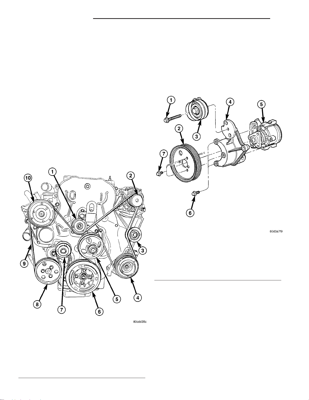
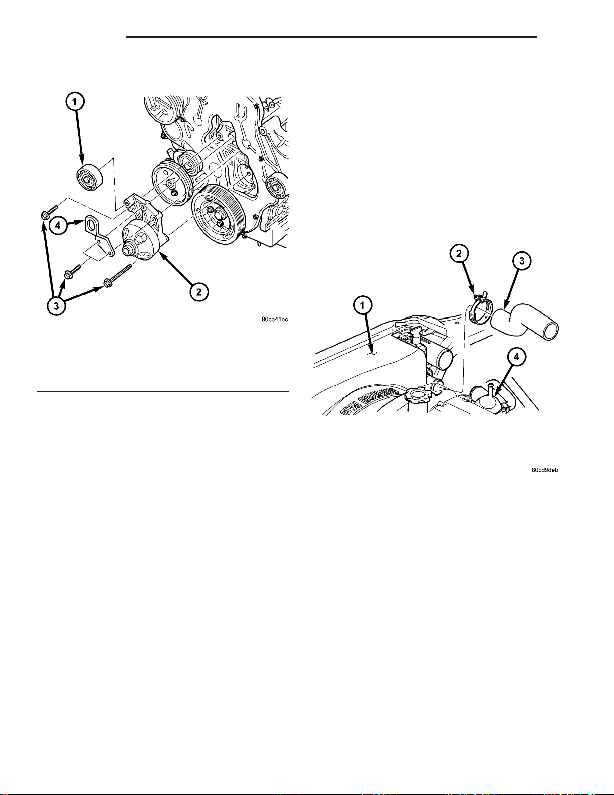
Fig. 3 BELT TENSIONER ASSEMBLY
1 - ACCESSORY BELT TENSIONER RETAINING BOLT
2 - POWER STEERING PUMP PULLEY
3 - BELT TENSIONER
4 - BRACKET
5 - POWER STEERING PUMP
6 - POWER STEERING PUMP RETAINING BOLTS
7 - POWER STEERING PUMP PULLEY RETAINING BOLTS
INSTALLATION
(1) Install belt tensioner on bracket (Fig. 3).
Torque retaining bolt to 47.1N·m.
(2) Install accessory drive belt (Fig. 2)(Refer to 7 COOLING/ACCESSORY DRIVE/DRIVE BELTS INSTALLATION).
(3) Connect negative battery cable.
Page 16
KJ ACCESSORY DRIVE 7 - 11
DRIVE BELT
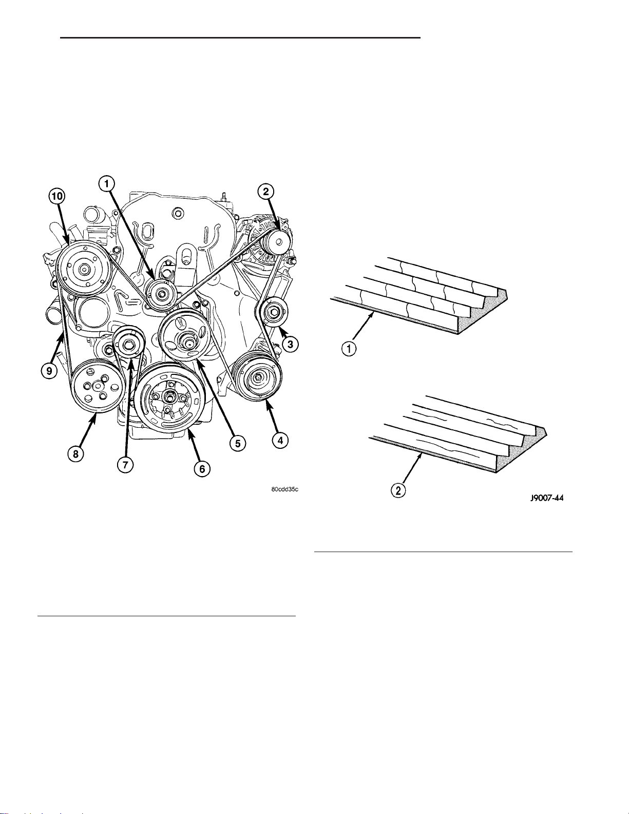
DESCRIPTION
The accessory drive belt is a serpentine type belt
(Fig. 4). Satisfactory performance of these belts
depends on belt condition and proper belt tension.
DIAGNOSIS AND TESTING - ACCESSORY DRIVE BELT
VISUAL DIAGNOSIS
When diagnosing serpentine accessory drive belts,
small cracks that run across the ribbed surface of the
belt from rib to rib (Fig. 5), are considered normal.
These are not a reason to replace the belt. However,
cracks running along a rib (not across) are not normal. Any belt with cracks running along a rib must
be replaced (Fig. 5). Also replace the belt if it has
excessive wear, frayed cords or severe glazing.
Refer to ACCESSORY DRIVE BELT DIAGNOSIS
CHART for further belt diagnosis.
Fig. 4 ACCESSORY BELT ROUTING
1 - IDLER PULLEY
2 - GENERATOR
3 - IDLER PULLEY
4 - A/C COMPRESSOR
5 - COOLING FAN SUPPORT
6 - VIBRATION DAMPER
7 - BELT TENSIONER
8 - POWER STEERING PUMP
9 - ACCESSORY DRIVE BELT
10 - VISCOUS HEATER
OPERATION-ACCESSORY DRIVE BELT
The accessory drive belts form the link between
the engine crankshaft and the engine driven accessories.
Fig. 5 BELT WEAR PATTERN
1 - NORMAL CRACKS BELT OK
2 - NOT NORMAL CRACKS REPLACE BELT
NOISE DIAGNOSIS
Noises generated by the accessory drive belt are
most noticeable at idle. Before replacing a belt to
resolve a noise condition, inspect all of the accessory
drive pulleys for alignment, glazing, or excessive end
play.
Page 17

7 - 12 ACCESSORY DRIVE KJ
DRIVE BELT (Continued)
ACCESSORY DRIVE BELT DIAGNOSIS CHART
CONDITION POSSIBLE CAUSES CORRECTION
RIB CHUNKING (One or more ribs
has separated from belt body)
RIB OR BELT WEAR 1. Pulley misaligned 1. Align pulley(s)
BELT SLIPS 1. Belt slipping because of
1. Foreign objects imbedded in
pulley grooves.
2. Installation damage 2. Replace belt
2. Abrasive environment 2. Clean pulley(s). Replace belt if
3. Rusted pulley(s) 3. Clean rust from pulley(s)
4. Sharp or jagged pulley groove
tips
5. Belt rubber deteriorated 5. Replace belt
insufficient tension
2. Belt or pulley exposed to
substance that has reduced friction
(belt dressing, oil, ethylene glycol)
3. Driven component bearing failure
(seizure)
4. Belt glazed or hardened from
heat and excessive slippage
1. Remove foreign objects from
pulley grooves. Replace belt.
necessary
4. Replace pulley. Inspect belt.
1. Inspect/Replace tensioner if
necessary
2. Replace belt and clean pulleys
3. Replace faulty component or
bearing
4. Replace belt.
LONGITUDAL BELT CRACKING 1. Belt has mistracked from pulley
groove
2. Pulley groove tip has worn away
rubber to tensile member
9GROOVE JUMPING9
(Belt does not maintain correct
position on pulley)
BELT BROKEN
(Note: Identify and correct problem
before new belt is installed)
1. Incorrect belt tension 1. Inspect/Replace tensioner if
2. Pulley(s) not within design
tolerance
3. Foreign object(s) in grooves 3. Remove foreign objects from
4. Pulley misalignment 4. Align component
5. Belt cordline is broken 5. Replace belt
1. Incorrect belt tension 1. Replace Inspect/Replace
2. Tensile member damaged during
belt installation
3. Severe misalignment 3. Align pulley(s)
4. Bracket, pulley, or bearing failure 4. Replace defective component
1. Replace belt
2. Replace belt
necessary
2. Replace pulley(s)
grooves
tensioner if necessary
2. Replace belt
and belt
Page 18

KJ ACCESSORY DRIVE 7 - 13
DRIVE BELT (Continued)
CONDITION POSSIBLE CAUSES CORRECTION
NOISE
(Objectionable squeal, squeak, or
rumble is heard or felt while drive
belt is in operation)
TENSION SHEETING FABRIC
FAILURE
(Woven fabric on outside,
circumference of belt has cracked or
separated from body of belt)
CORD EDGE FAILURE
(Tensile member exposed at edges
of belt or separated from belt body)
1. Incorrect belt tension 1. Inspect/Replace tensioner if
necessary
2. Bearing noise 2. Locate and repair
3. Belt misalignment 3. Align belt/pulley(s)
4. Belt to pulley mismatch 4. Install correct belt
5. Driven component induced
vibration
1. Tension sheeting contacting
stationary object
2. Excessive heat causing woven
fabric to age
3. Tension sheeting splice has
fractured
1. Incorrect belt tension 1. Inspect/Replace tensioner if
2. Belt contacting stationary object 2. Replace belt
3. Pulley(s) out of tolerance 3. Replace pulley
4. Insufficient adhesion between
tensile member and rubber matrix
5. Locate defective driven
component and repair
1. Correct rubbing condition
2. Replace belt
3. Replace belt
necessary
4. Replace belt
REMOVAL
NOTE: The belt routing schematics are published
from the latest information available at the time of
publication. If anything differs between these schematics and the Belt Routing Label, use the schematics on Belt Routing Label. This label is located
in the engine compartment.
CAUTION: DO NOT LET TENSIONER ARM SNAP
BACK TO THE FREEARM POSITION, SEVERE DAMAGE MAY OCCUR TO THE TENSIONER.
Belt tension is not adjustable. Belt adjustment is
maintained by an automatic (spring loaded) belt tensioner.
(1) Disconnect negative battery cable.
(2) Rotate belt tensioner until it contacts its stop.
Remove belt, then slowly rotate the tensioner into
the freearm position.
INSTALLATION
NOTE: The belt routing schematics are published
from the latest information available at the time of
publication. If anything differs between these schematics and the Belt Routing Label, use the schematics on Belt Routing Label. This label is located
in the engine compartment.
Belt tension is not adjustable. Belt adjustment is
maintained by an automatic ( spring load ) belt tensioner.
(1) Check condition of all pulleys.
CAUTION: When installing the serpentine accessory
drive belt, the belt MUST be routed correctly. If not,
the engine may overheat due to the water pump
rotating in the wrong direction.
Page 19
7 - 14 ACCESSORY DRIVE KJ
DRIVE BELT (Continued)
(2) Install new belt. Route the belt around all pulleys except the idler pulley (Fig. 6). Rotate the tensioner arm until it contacts its stop position. Route
the belt around the idler and slowly let the tensioner
rotate into the belt. Make sure the belt is seated onto
all pulleys (Fig. 6).
IDLER PULLEYS
REMOVAL
CAUTION: The retaining bolts on the idler pulleys
are left hand thread.
(1) Disconnect negative battery cable.
(2) Remove accessory drive belt (Refer to 7 COOLING/ACCESSORY DRIVE/DRIVE BELTS REMOVAL).
(3) Remove idler pulley retaining bolts and pulleys
(Fig. 7) (Fig. 8).
Fig. 6 ACCESSORY BELT ROUTING
1 - IDLER PULLEY
2 - GENERATOR
3 - IDLER PULLEY
4 - A/C COMPRESSOR
5 - COOLING FAN SUPPORT
6 - VIBRATION DAMPER
7 - BELT TENSIONER
8 - POWER STEERING PUMP
9 - ACCESSORY DRIVE BELT
10 - VISCOUS HEATER
Fig. 7 COOLING FAN SUPPORT
1 - IDLER PULLEY
2 - COOLING FAN SUPPORT
3 - RETAINING BOLTS
4 - ENGINE LIFT HOOK
Page 20
KJ ACCESSORY DRIVE 7 - 15
IDLER PULLEYS (Continued)
INSTALLATION
(1) Install idler pulleys and retaining bolts (Fig. 7)
(Fig. 8). Torque bolts to 53N·m.
(2) Install accessory drive belt (Refer to 7 - COOLING/ACCESSORY DRIVE/DRIVE BELTS - INSTALLATION).
(3) Connect negative battery cable.
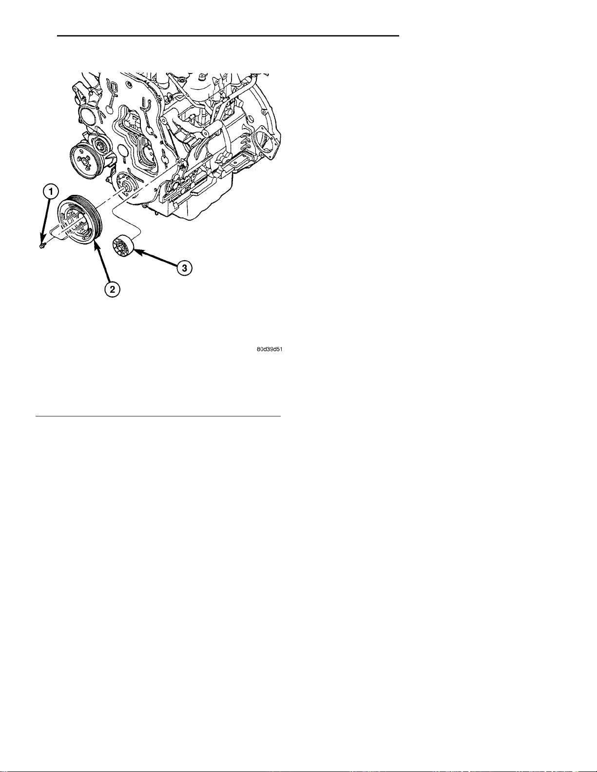
Fig. 8 VIBRATION DAMPER AND IDLER PULLEY
1 - VIBRATION DAMPER/CRANKSHAFT PULLEY RETAINING
BOLTS
2 - VIBRATION DAMPER/CRANKSHAFT PULLEY
3 - IDLER PULLEY
Page 21

7 - 16 ENGINE KJ
ENGINE
TABLE OF CONTENTS
page page
COOLANT
STANDARD PROCEDURE
STANDARD PROCEDURE—DRAINING
COOLING SYSTEM ....................16
STANDARD PROCEDURE - COOLING
SYSTEM FILLING .....................17
STANDARD PROCEDURE - REFILLING
COOLING SYSTEM ....................17
COOLANT RECOVERY PRESS CONTAINER
DESCRIPTION .........................17
OPERATION ...........................17
COOLING FAN
REMOVAL
REMOVAL - COOLING FAN ..............17
REMOVAL - COOLING FAN SUPPORT .....17
CLEANING ............................17
INSPECTION ..........................17
INSTALLATION
INSTALLATION - COOLING FAN ..........18
INSTALLATION - COOLING FAN SUPPORT . . 18
COOLANT SYSTEM HOSES
REMOVAL
REMOVAL - UPPER RADIATOR HOSE .....18
REMOVAL - HEATER CORE HOSES .......18
INSTALLATION
INSTALLATION - UPPER RADIATOR HOSE . . 19
INSTALLATION – HEATER CORE HOSES . . . 19
ENGINE COOLANT TEMP SENSOR
DESCRIPTION .........................19
OPERATION ...........................19
REMOVAL .............................20
INSTALLATION .........................20
ENGINE COOLANT THERMOSTAT
DESCRIPTION .........................20
OPERATION ...........................20
REMOVAL .............................20
INSTALLATION .........................21
FAN DRIVE VISCOUS CLUTCH
DESCRIPTION .........................21
OPERATION ...........................22
DIAGNOSIS AND TESTING - FAN DRIVE
VISCOUS CLUTCH ....................22
REMOVAL .............................22
INSTALLATION .........................23
RADIATOR
REMOVAL .............................23
INSTALLATION .........................24
WATER PUMP
DESCRIPTION .........................24
OPERATION ...........................24
REMOVAL - WATER PUMP ................24
CLEANING ............................24
INSTALLATION .........................25
RADIATOR PRESSURE CAP
DESCRIPTION .........................25
OPERATION ...........................25
DIAGNOSIS AND TESTING
DIAGNOSIS AND TESTING - COOLING
SYSTEM PRESSURE CAP...............25
DIAGNOSIS AND TESTING - PRESSURE
RELIEF TEST ........................25
CLEANING ............................26
INSPECTION ..........................26
HOSE CLAMPS
DESCRIPTION - HOSE CLAMPS ...........26
OPERATION - HOSE CLAMPS .............27
COOLANT
STANDARD PROCEDURE
STANDARD PROCEDURE—DRAINING COOLING SYSTEM
WARNING: DO NOT REMOVE THE CYLINDER
BLOCK DRAIN PLUGS OR LOOSEN THE RADIATOR
DRAINCOCK WITH SYSTEM HOT AND UNDER
PRESSURE. SERIOUS BURNS FROM COOLANT
CAN OCCUR.
(1) DO NOT remove radiator cap first. With engine
cold, raise vehicle on a hoist and locate radiator
draincock.
NOTE: Radiator draincock is located on the Right/
lower side of radiator facing to rear of vehicle.
(2) Attach one end of a hose to the draincock. Put
the other end into a clean container. Open draincock
and drain coolant from radiator. This will empty the
coolant reserve/overflow tank. The coolant does not
have to be removed from the tank unless the system
is being refilled with a fresh mixture. Remove radiator cap and continue draining cooling system.
Page 22

KJ ENGINE 7 - 17
COOLANT (Continued)
STANDARD PROCEDURE - COOLING SYSTEM FILLING
Remove pressure/vent cap and fill system, using a
50/50 mix of Mopart Antifreeze/Coolant, 5
Year/100,000 Mile Formula and distilled water.
Continue filling system until full. Be careful not
to spill coolant on drive belts or the generator.
Fill coolant recovery pressure container to at least
the MAX mark with 50/50 solution. It may be necessary to add coolant to the coolant recovery pressure
container after three or four warm up/cool down
cycles to maintain coolant level between the MAX
and MIN mark. This will allow trapped air to be
removed from the system.
STANDARD PROCEDURE - REFILLING COOLING SYSTEM
(1) Tighten the radiator draincock and the cylinder
block drain plug(s) (if removed).
CAUTION: Failure to purge air from the cooling system can result in an overheating condition and
severe engine damage.
As the engine cools, a vacuum is formed in the
cooling system of both the radiator and engine. Coolant will then be drawn from the coolant tank and
returned to a proper level in the radiator.
The coolant reservoir/overflow system has a radiator mounted pressurized cap, an overflow tube, and a
plastic coolant reservoir/overflow tank, mounted to
the right side of the cowl. It is mounted to the cowl
with two nuts on top, and a slide bracket on the bottom.
OPERATION
The pressure chamber keeps the coolant free of
trapped air, provides a volume for expansion and contraction, and provides a convenient and safe method
for checking and adjusting coolant level at atmospheric pressure. It also provides some reserve coolant to cover minor leaks, evaporation or boiling
losses. The overflow chamber allows coolant recovery
in case of an overheat.
COOLING FAN
(2) Fill system using a 50/50 mixture of ethyleneglycol antifreeze and low mineral content water, until
coolant remains in the bottom of the coolant reserve/
overflow. Install radiator cap.
(3) With heater control unit in the HEAT position,
operate engine with radiator cap in place.
(4) After engine has reached normal operating
temperature, shut engine off and allow it to cool.
When engine is cooling down, coolant will be drawn
into the radiator from the reserve/overflow tank.
(5) Add coolant to reserve/overflow tank as necessary. Only add coolant to the reserve/overflow
tank when the engine is cold. Coolant level in a
warm engine will be higher due to thermal
expansion.
COOLANT RECOVERY PRESS CONTAINER
DESCRIPTION
This system works along with the radiator pressure cap. This is done by using thermal expansion
and contraction of the coolant to keep the coolant
free of trapped air. It provides:
• A volume for coolant expansion and contraction.
• A convenient and safe method for checking/ad-
justing coolant level at atmospheric pressure. This is
done without removing the radiator pressure cap.
• Some reserve coolant to the radiator to cover
minor leaks and evaporation or boiling losses.
REMOVAL
REMOVAL - COOLING FAN
(1) (Refer to 7 - COOLING/ENGINE/FAN DRIVE
VISCOUS CLUTCH - REMOVAL)
REMOVAL - COOLING FAN SUPPORT
(1) Disconnect negative battery cable.
(2) Remove fan drive viscous clutch and fan
assembly (Refer to 7 - COOLING/ENGINE/FAN
DRIVE VISCOUS CLUTCH - REMOVAL).
(3) Remove cooling fan support from engine block
(Fig. 1).
CLEANING
Clean the fan blades using a mild soap and water.
Do not use an abrasive to clean the blades.
INSPECTION
WARNING: DO NOT ATTEMPT TO BEND OR
STRAIGHTEN FAN BLADES IF FAN IS NOT WITHIN
SPECIFICATIONS.
CAUTION: If fan blade assembly is replaced
because of mechanical damage, water pump and
fan drive viscous clutch should also be inspected.
These components could have been damaged due
to excessive vibration.
Page 23
7 - 18 ENGINE KJ
COOLING FAN (Continued)
COOLANT SYSTEM HOSES
REMOVAL
REMOVAL - UPPER RADIATOR HOSE
(1) Drain cooling system (Refer to 7 - COOLING/
ENGINE/COOLANT - STANDARD PROCEDURE).
(2) Disconnect upper radiator hose from thermostat housing (Fig. 2).
(3) Disconnect upper radiator hose from radiator
and remove from vehicle (Fig. 2).
Fig. 1 COOLING FAN SUPPORT
1 - IDLER PULLEY
2 - COOLING FAN SUPPORT
3 - RETAINING BOLTS
4 - ENGINE LIFT HOOK
(1) Remove fan blade assembly from fan drive vis-
cous clutch (four bolts).
(2) Lay fan on a flat surface with leading edge facing down. With tip of blade touching flat surface,
replace fan if clearance between opposite blade and
surface is greater than 2.0 mm (.090 inch). Rocking
motion of opposite blades should not exceed 2.0 mm
(.090 inch). Test all blades in this manner.
(3) Inspect fan assembly for cracks, bends, loose
rivets or broken welds. Replace fan if any damage is
found.
INSTALLATION
INSTALLATION - COOLING FAN
(1) (Refer to 7 - COOLING/ENGINE/FAN DRIVE
VISCOUS CLUTCH - INSTALLATION)
INSTALLATION - COOLING FAN SUPPORT
(1) Install cooling fan support to engine block (Fig.
1). Torque bolts to 47.1N·m.
(2) Install fan drive viscous clutch and fan assembly (Refer to 7 - COOLING/ENGINE/FAN DRIVE
VISCOUS CLUTCH - INSTALLATION).
(3) Connect negative battery cable.
Fig. 2 UPPER RADIATOR HOSE
1 - FAN SHROUD
2 - HOSE CLAMP
3 - UPPER RADIATOR HOSE
4 - THERMOSTAT HOUSING
REMOVAL - HEATER CORE HOSES
(1) Drain cooling system (Refer to 7 - COOLING/
ENGINE/COOLANT - STANDARD PROCEDURE).
(2) Remove engine cover from engine (Refer to 9 -
ENGINE COVER - REMOVAL).
(3) Disconnect heater core supply line at heater
core and viscous heater (Fig. 3). Remove hose from
vehicle.
(4) Disconnect heater core return line from heater
core and EGR cooler (Fig. 3). Remove hose from vehicle.
Page 24
KJ ENGINE 7 - 19
COOLANT SYSTEM HOSES (Continued)
ENGINE COOLANT TEMP SENSOR
DESCRIPTION
The engine coolant temperature sensor threads
into a coolant passage in the cylinder head (Fig. 4).
New sensors have sealant applied to the threads.
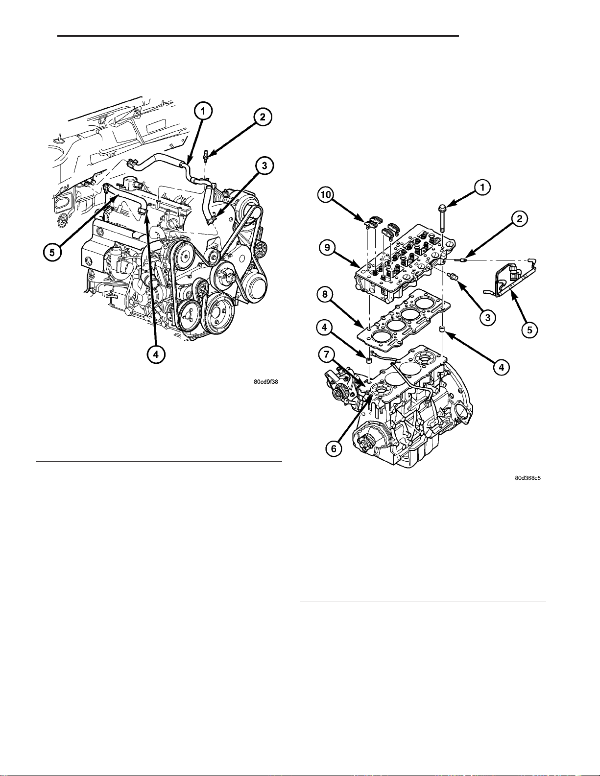
Fig. 3 HEATER CORE COOLANT HOSES
1 - HEATER CORE TO VISCOUS HEATER HOSE
2 - MOUNTING STUD
3 - HOSE CLAMP
4 - HOSE CLAMP
5 - HEATER CORE TO EGR COOLER HOSE
INSTALLATION
INSTALLATION - UPPER RADIATOR HOSE
(1) Install upper radiator hose on radiator and
thermostat housing (Fig. 2).
(2) Reposition hose clamps in proper position.
(3) Refill cooling system to proper level (Refer to 7
- COOLING/ENGINE/COOLANT - STANDARD PROCEDURE).
INSTALLATION – HEATER CORE HOSES
(1) Connect heater core supply hose to heater core
and viscous heater. Position hose clamps into proper
position.
(2) Connect heater core return hose to heater core
and EGR cooler. Position hose clamps into proper
position.
(3) Install engine cover to engine (Refer to 9 ENGINE COVER - INSTALLATION).
(4) Refill cooling system to proper level (Refer to 7
- COOLING/ENGINE/COOLANT - STANDARD PROCEDURE).
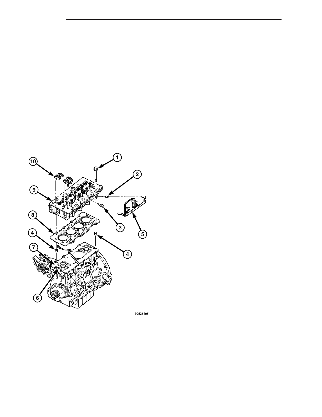
Fig. 4 CYLINDER HEAD ASSEMBLY
1 - CYLINDER HEAD BOLT
2 - GLOW PLUG
3 - COOLANT TEMPERATURE SENSOR
4 - CYLINDER HEAD ALIGNMENT DOWEL
5 - GLOW PLUG HARNESS
6 - CYLINDER LINER
7 - CYLINDER BLOCK
8 - CYLINDER HEAD GASKET
9 - CYLINDER HEAD
10 - ROCKER ARM ASSEMBLIES
OPERATION
The coolant temperature (ECT) sensor is a negative temperature coefficient (NTC) thermistor (resistance varies inversley with temperature). This means
at cold tempertures its resistance is high so the voltage signal will be high. As coolant temperture
increases, resistance decreases and the signal voltage
will be low. This allows the sensor to provide an analog voltage signal to the ECM.
Page 25
7 - 20 ENGINE KJ
ENGINE COOLANT TEMP SENSOR (Continued)
REMOVAL
WARNING: DO NOT REMOVE OR LOOSEN THE
COOLANT PRESSURE/VENT CAP, CYLINDER
BLOCK DRAIN PLUGS, OR THE DRAINCOCK WHEN
THE SYSTEM IS HOT AND UNDER PRESSURE
BECAUSE SERIOUS BURNS FROM THE COOLANT
CAN OCCUR.
(1) Disconnect negative battery cable.
(2) Drain the cooling system. (Refer to 7 - COOLING/ENGINE/COOLANT - STANDARD PROCEDURE)
(3) Disconnect coolant temperature sensor electrical connector (Fig. 5).
(4) Remove coolant temperature sensor from cylinder head (Fig. 5).
INSTALLATION
(1) Install coolant temperature sensor in cylinder
head (Fig. 5).
(2) Connect coolant temperature sensor electrical
connector (Fig. 5).
(3) Refill cooling system. (Refer to 7 - COOLING/
ENGINE/COOLANT - STANDARD PROCEDURE)
(4) Connect negative battery cable.
ENGINE COOLANT THERMOSTAT
DESCRIPTION
A pellet-type thermostat controls the operating
temperature of the engine by controlling the amount
of coolant flow to the radiator (Fig. 6).
OPERATION
The thermostat starts to open at 80°C (176°F).
Above this temperature, coolant is allowed to flow to
the radiator. This provides quicker engine warmup
and overall temperature control.
The same thermostat is used for winter and summer seasons. An engine should not be operated without a thermostat, except for servicing or testing.
Operating without a thermostat causes other problems. These are: longer engine warmup time, unreliable warmup performance, increased exhaust
emissions and crankcase condensation. This condensation can result in sludge formation.
Fig. 5 CYLINDER HEAD ASSEMBLY
1 - CYLINDER HEAD BOLT
2 - GLOW PLUG
3 - COOLANT TEMPERATURE SENSOR
4 - CYLINDER HEAD ALIGNMENT DOWEL
5 - GLOW PLUG HARNESS
6 - CYLINDER LINER
7 - CYLINDER BLOCK
8 - CYLINDER HEAD GASKET
9 - CYLINDER HEAD
10 - ROCKER ARM ASSEMBLIES
REMOVAL
NOTE: The thermostat is not serviced separately.
The thermostat and housing must be replaced as
an assembly.
(1) Disconnect negative battery cable.
(2) Remove engine cover (Refer to 9 - ENGINE
COVER - REMOVAL).
(3) Partially drain cooling system (Refer to 7 COOLING/ENGINE/COOLANT - STANDARD PROCEDURE).
(4) Disconnect upper radiator hose and bypass
hoses at thermostat housing.
(5) Remove thermostat housing retaining bolts,
support bracket (2.8L) and housing from cylinder
head, discard gasket (Fig. 7).
Page 26
KJ ENGINE 7 - 21
ENGINE COOLANT THERMOSTAT (Continued)
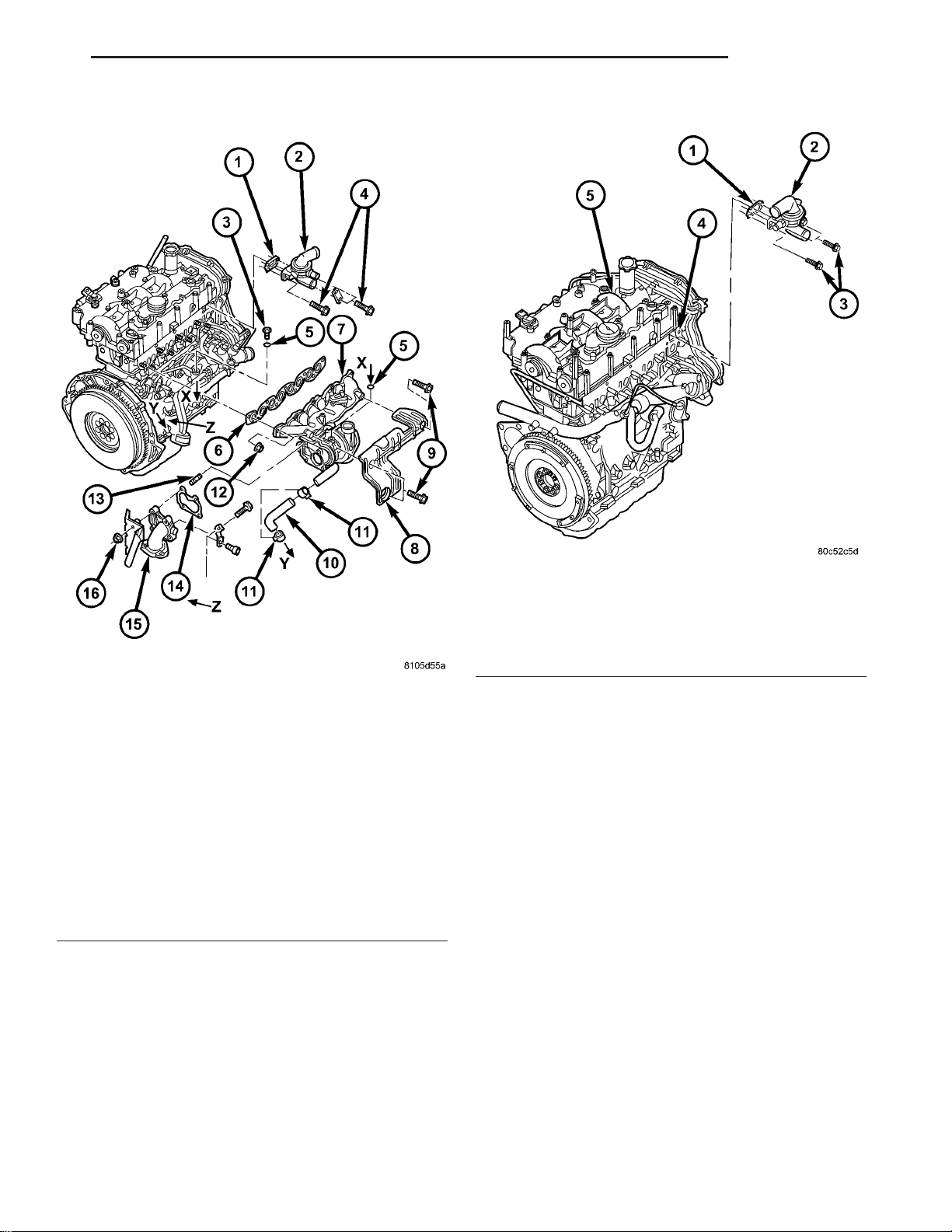
Fig. 6 THERMOSTAT HOUSING
1 - THERMOSTAT HOUSING GASKET
2 - THERMOSTAT HOUSING
3 - TURBOCHARGER OIL SUPPLY LINE BANJO BOLT
4 - THERMOSTAT HOUSING RETAINING BOLTS
5 - BRASS WASHER
6 - EXHAUST MANIFOLD GASKET
7 - EXHAUST MANIFOLD
8 - EXHAUST MANIFOLD HEATSHIELD
9 - EXHAUST MANIFOLD HEATSHIELD RETAINING BOLTS
10 - OIL RETURN HOSE
11 - HOSE CLAMPS
12 - EXHAUST MANIFOLD RETAINING NUTS
13 - TURBOCHARGER DOWNPIPE STUDS
14 - TURBOCHARGER DOWN PIPE GASKET
15 - TURBOCHARGER DOWNPIPE
16 - TURBOCHARGER DOWNPIPE RETAINING NUT
INSTALLATION
(1) Clean old gasket material from cylinder head
and thermostat housing.
(2) Install thermostat housing with gasket and
support bracket (2.8L) to cylinder head (Fig. 7).
Torque bolts to 27.5N·m.
(3) Connect coolant bypass hose and upper radiator hose to thermostat housing.
(4) Refill cooling system (Refer to 7 - COOLING/
ENGINE/COOLANT - STANDARD PROCEDURE).
Fig. 7 THERMOSTAT HOUSING ASSEMBLY
1 - THERMOSTAT HOUSING GASKET
2 - THERMOSTAT HOUSING
3 - RETAINING BOLTS
4 - CYLINDER HEAD
5 - CYLINDER HEAD COVER/INTAKE MANIFOLD
(5) Install engine cover (Refer to 9 - ENGINE
COVER - INSTALLATION).
(6) Connect negative battery cable.
FAN DRIVE VISCOUS CLUTCH
DESCRIPTION
CAUTION: If the viscous fan drive is replaced
because of mechanical damage, the cooling fan
blades should also be inspected. Inspect for fatigue
cracks, loose blades, or loose rivets that could
have resulted from excessive vibration. Replace fan
blade assembly if any of these conditions are
found. Also inspect water pump bearing and shaft
assembly for any related damage due to a viscous
fan drive malfunction.
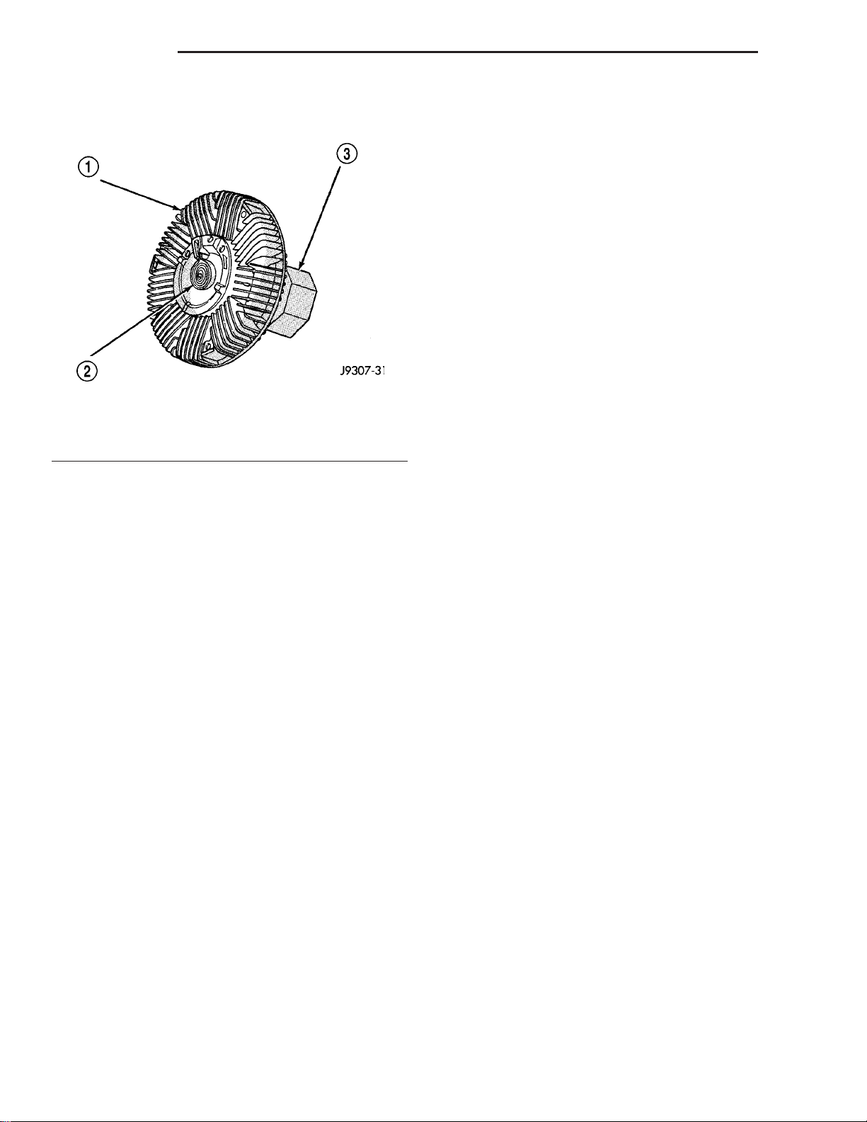
The thermal viscous fan drive (Fig. 8) is a siliconefluid-filled coupling used to connect the fan blades to
the fan support bracket assembly. The coupling
allows the fan to be driven in a normal manner. This
is done at low engine speeds while limiting the top
speed of the fan to a predetermined maximum level
at higher engine speeds.
Page 27
7 - 22 ENGINE KJ
FAN DRIVE VISCOUS CLUTCH (Continued)
On the 2.5L Diesel engine, a viscous fan is stan-
dard.
Fig. 8 Viscous Fan Drive - Typical
1 - VISCOUS FAN DRIVE
2 - THERMOSTATIC SPRING
3 - MOUNTING NUT TO WATER PUMP HUB
OPERATION
A thermostatic bimetallic spring coil is located on
the front face of the viscous fan drive unit. This
spring coil reacts to the temperature of the radiator
discharge air. It engages the viscous fan drive for
higher fan speed if the air temperature from the
radiator rises above a certain point. Until additional
engine cooling is necessary, the fan will remain at
a reduced rpm regardless of engine speed. Normally less than three hundred (300) rpm.
Only when sufficient heat is present, will the viscous fan drive engage. This is when the air flowing
through the radiator core causes a reaction to the
bimetallic coil. It then increases fan speed to provide
the necessary additional engine cooling.
Once the engine has cooled, the radiator discharge
temperature will drop. The bimetallic coil again
reacts and the fan speed is reduced to the previous
disengaged speed.
DIAGNOSIS AND TESTING - FAN DRIVE VISCOUS CLUTCH
If the fan assembly free-wheels without drag (the
fan blades will revolve more than five turns when
spun by hand), replace the fan drive. This spin test
must be performed when the engine is cool.
For the following test, the cooling system must be
in good condition. It also will ensure against excessively high coolant temperature.
WARNING: BE SURE THAT THERE IS ADEQUATE
FAN BLADE CLEARANCE BEFORE DRILLING.
(1) Drill a 3.18-mm (1/8-in) diameter hole in the
top center of the fan shroud.
(2) Obtain a dial thermometer with an 8 inch stem
(or equivalent). It should have a range of -18° to
105°C (0° to 220° F). Insert thermometer through the
hole in the shroud. Be sure that there is adequate
clearance from the fan blades.
(3) Connect a tachometer and an engine ignition
timing light (timing light is to be used as a strobe
light).
(4) Block the air flow through the radiator. Secure
a sheet of plastic in front of the radiator (or air conditioner condenser). Use tape at the top to secure the
plastic and be sure that the air flow is blocked.
(5) Be sure that the air conditioner (if equipped) is
turned off.
WARNING: USE EXTREME CAUTION WHEN THE
ENGINE IS OPERATING. DO NOT STAND IN A
DIRECT LINE WITH THE FAN. DO NOT PUT YOUR
HANDS NEAR THE PULLEYS, BELTS OR FAN. DO
NOT WEAR LOOSE CLOTHING.
(6) Start the engine and operate at 2400 rpm.
Within ten minutes the air temperature (indicated on
the dial thermometer) should be up to 93° C (200° F).
Fan drive engagement should have started to occur
at between 91° to 96° C (195° to 205° F). Engagement is distinguishable by a definite increase in fan
flow noise (roaring). The timing light also will indicate an increase in the speed of the fan.
(7) When the air temperature reaches 93° C (200°
F), remove the plastic sheet. Fan drive disengage-
ment should have started to occur at between 62° to
85° C (145° to 185° F). A definite decrease of fan
flow noise (roaring) should be noticed. If not, replace
the defective viscous fan drive unit.
REMOVAL
(1) Disconnect negative battery cable.
NOTE: The thermal viscous fan drive/fan blade
assembly is attached (threaded) to fan support.
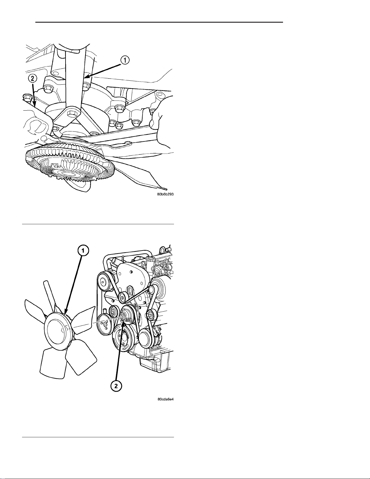
(2) Remove fan blade/viscous fan drive assembly
from water pump using special tool 6958 spanner
wrench, by turning mounting nut counterclockwise
as viewed from front (Fig. 9) (Fig. 10). Threads on
viscous fan drive are RIGHT HAND.
(3) Do not attempt to remove fan/fan drive viscous
clutch assembly from vehicle at this time.
(4) Do not unbolt fan blade assembly from fan
drive viscous clutch at this time.
(5) Remove fan shroud to radiator bolts.
(6) Remove fan shroud and fan blade/fan drive viscous clutch assembly as a complete unit from vehicle.
Page 28
KJ ENGINE 7 - 23
FAN DRIVE VISCOUS CLUTCH (Continued)
(7) After removing fan blade/fan drive viscous
clutch assembly, do not place viscous clutch in horizontal position. If stored horizontally, silicone fluid in
the fan drive viscous clutch could drain into its bearing assembly and contaminate lubricant.
(8) Remove four bolts securing fan blade assembly
to fan drive viscous clutch.
INSTALLATION
(1) Assemble fan blade to viscous fan drive.
Tighten mounting bolts to 27 N·m (20 ft. lbs.) torque.
NOTE: The viscous fan and fan shroud must be
installed as an assembly.
(2) Gently lay fan and viscous drive into fan
shroud.
(3) Install the fan shroud to radiator mounting
bolt. Torque bolts to 5.5N·m.
(4) Thread the fan and viscous drive onto the fan
support and tighten nut using special tool 6958 spanner wrench.
Fig. 9 FAN DRIVE VISCOUS CLUTCH - TYPICAL
1 - SPECIAL TOOL 6958 SPANNER WRENCH
2-FAN
(5) Connect negative battery cable.
RADIATOR
Fig. 10 COOLING FAN AND VISCOUS CLUTCH
1 - COOLING FAN AND FAN DRIVE VISCOUS CLUTCH
ASSEMBLY
2 - FAN SUPPORT
REMOVAL
(1) Disconnect negative battery cable.
(2) Drain cooling system (Refer to 7 - COOLING/
ENGINE - STANDARD PROCEDURE).
(3) Remove engine oil fill cap.
(4) Remove engine cover (Refer to 9 - ENGINE
COVER - REMOVAL).
(5) Remove air filter assembly from the engine bay.
(6) Recover and evacuate the refrigerant system
(Refer to 24 - HEATING & AIR CONDITIONING/
PLUMBING - STANDARD PROCEDURE) and (Refer
to 24 - HEATING & AIR CONDITIONING/PLUMBING - STANDARD PROCEDURE).
(7) Disconnect high side refrigerant line from the
upper radiator support bracket.
(8) Remove upper radiator support bracket retaining bolts and remove the support bracket.
(9) Remove high side refrigerant line retaining nut
and remove the line from the condenser assembly.
Position the line out of the way.
(10) Unbolt cooling fan from cooling fan support.
(11) Remove fan shroud retaining bolts and
remove the fan and shroud as an assembly.
(12) Disconnect charge air cooler hoses from the
charge air cooler.
(13) Disconnect engine coolant hoses from the radiator.
(14) Disconnect coolant reservoir hose from the
radiator.
Page 29
7 - 24 ENGINE KJ
RADIATOR (Continued)
(15) Remove low side refrigerant line retaining nut
and remove the line from the condenser assembly.
Position the line out of the way.
(16) Remove condenser assembly retaining bolts
and remove the condenser from the vehicle.
(17) Remove power steering cooler retaining bolts
and unclip the air deflectors from both sides of the
radiator (cooling module) assembly.
(18) Lift cooling module assembly out of the engine
bay.
(19) Remove radiator retaining bolts and remove
the cooling system module from vehicle.
(20) Separate charge air cooler from radiator.
INSTALLATION
(1) Install radiator on the charge air cooler and
install retaining bolts.
(2) Install radiator (cooling module) assembly in
the engine bay.
(3) Install power steering cooler retaining bolts
and clip the air deflectors on both sides of the radiator (cooling module) assembly.
(4) Install condenser assembly and retaining bolts.
(5) Install low side refrigerant line and retaining
nut.
(6) Connect coolant reservoir hose on the radiator.
(7) Connect engine coolant hoses on the radiator.
(8) Connect charge air cooler hoses on the charge
air cooler.
(9) Install fan and fan shroud assembly and
retaining bolts.
(10) Install cooling fan assembly to cooling fan
support.
(11) Install high side refrigerant line and retaining
nut.
(12) Install upper radiator support bracket and
retaining bolts.
(13) Connect high side refrigerant line on the
upper radiator support bracket.
(14) Evacuate and re-charge the refrigerant system (Refer to 24 - HEATING & AIR CONDITIONING/PLUMBING - STANDARD PROCEDURE).
(15) Install air filter assembly in the engine bay.
(16) Install engine cover (Refer to 9 - ENGINE
COVER - INSTALLATION).
(17) refill cooling system (Refer to 7 - COOLING/
ENGINE - STANDARD PROCEDURE).
(18) Connect negative battery cable.
WATER PUMP
DESCRIPTION
The water pump on the 2.5L/2.8L CRD diesel has a
die cast aluminum housing. It bolts to a aluminum
housing which attaches to the engine block.
OPERATION
The water pump is used to circulate coolant
through the cooling system. The coolant is pumped
through the engine block, cylinder head, heater core,
EGR cooler, viscous heater, and radiator.
REMOVAL - WATER PUMP
(1) Disconnect negative battery cable.
(2) Drain cooling system (Refer to 7 - COOLING/
ENGINE/COOLANT - STANDARD PROCEDURE).
(3) Remove timing belt inner and outer covers
(Refer to 9 - ENGINE/VALVE TIMING/TIMING
BELT / CHAIN COVER(S) - REMOVAL).
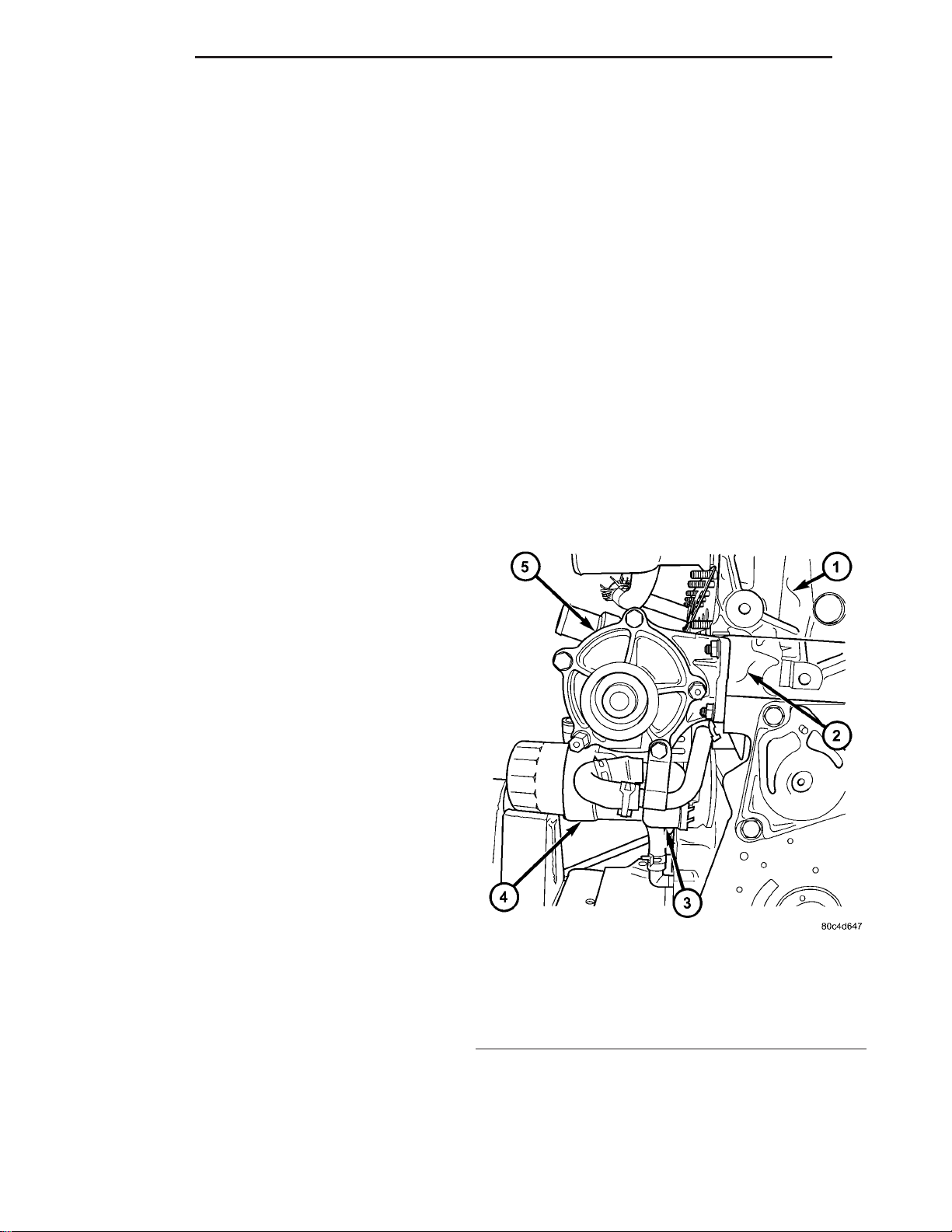
(4) Remove water pump retaining bolts and pump
(Fig. 11).
Fig. 11 WATER PUMP LOCATION
1 - CYLINDER HEAD
2 - ENGINE BLOCK
3 - OIL COOLER
4 - OIL FILTER HOUSING
5 - WATER PUMP
CLEANING
Clean gasket mating surfaces as necessary.
Page 30

KJ ENGINE 7 - 25
WATER PUMP (Continued)
INSTALLATION
(1) Clean mating surfaces of water pump housing
and engine block as necessary.
(2) Place new o-ring in groove in water pump
housing. Install water pump and retaining bolts.
Torque bolts to 24.4N·m.
(3) Install both inner and outer timing belt covers
(Refer to 9 - ENGINE/VALVE TIMING/TIMING
BELT / CHAIN COVER(S) - INSTALLATION).
(4) Refill cooling system (Refer to 7 - COOLING/
ENGINE/COOLANT - STANDARD PROCEDURE).
(5) Connect negative battery cable.
RADIATOR PRESSURE CAP
DESCRIPTION
The cooling system pressure cap is located on the
coolant recovery pressure container. The cap construction includes; stainless steel swivel top, rubber
seals, and retainer, main spring, and a spring loaded
valve (Fig. 12).
through a connecting hose. If valve is stuck shut,
or the coolant recovery hose is pinched, the
radiator hoses will be collapsed on cool down.
Clean the vent valve (Fig. 12) and inspect coolant recovery hose routing, to ensure proper
sealing when boiling point is reached.
The gasket in the cap seals the filler neck, so that
vacuum can be maintained, allowing coolant to be
drawn back into the radiator from the reserve tank.
If the gasket is dirty or damaged, a vacuum
may not be achieved, resulting is loss of coolant
and eventual overheating due to low coolant
level in radiator and engine.
DIAGNOSIS AND TESTING
DIAGNOSIS AND TESTING - COOLING SYSTEM PRESSURE CAP
Dip the pressure cap in water. Clean any deposits
off the vent valve or its seat and apply cap to end of
the Pressure Cap Test Adaptor that is included with
the Cooling System Tester 7700. Working the
plunger, bring the pressure to 104 kPa (15 psi) on the
gauge. If the pressure cap fails to hold pressure of at
least 97 kPa (14 psi), replace the pressure cap.
Fig. 12 Cooling System Pressure Cap Filler Neck
1 - OVERFLOW NIPPLE
2 - MAIN SPRING
3 - GASKET RETAINER
4 - STAINLESS-STEEL SWIVEL TOP
5 - RUBBER SEALS
6 - VENT VALVE
7 - PRESSURE BOTTLE
8 - FILLER NECK
OPERATION
The cooling system is equipped with a pressure cap
that releases excessive pressure; maintaining a range
of 97-124 kPa (14-18 psi).
The cooling system will operate at higher than
atmospheric pressure. The higher pressure raises the
coolant boiling point thus, allowing increased radiator cooling capacity.
There is also a vent valve in the center of the cap.
This valve also opens when coolant is cooling and
contracting, allowing the coolant to return to cooling
system from coolant reserve system tank by vacuum
CAUTION: The Cooling System Tester Tool is very
sensitive to small air leaks that will not cause cooling system problems. A pressure cap that does not
have a history of coolant loss should not be
replaced just because it leaks slowly when tested
with this tool. Add water to the tool. Turn tool
upside down and recheck pressure cap to confirm
that cap is bad.
If the pressure cap tests properly while positioned
on Cooling System Tester (Fig. 13), but will not hold
pressure or vacuum when positioned on the filler
neck. Inspect the filler neck and cap top gasket for
irregularities that may prevent the cap from sealing
properly.
DIAGNOSIS AND TESTING - PRESSURE RELIEF TEST
The pressure cap upper gasket (seal) pressure
relief can be checked by removing the overflow hose
at the radiator filler neck nipple (Fig. 14). Attach the
Radiator Pressure Tool to the filler neck nipple and
pump air into the radiator. Pressure cap upper gasket should relieve at 69-124 kPa (10-18 psi) and hold
pressure at 55 kPa (8 psi) minimum.
Page 31

7 - 26 ENGINE KJ
RADIATOR PRESSURE CAP (Continued)
WARNING: IF VEHICLE HAS BEEN RUN RECENTLY,
WAIT 15 MINUTES BEFORE REMOVING CAP. THEN
PLACE A SHOP TOWEL OVER THE CAP AND WITHOUT PUSHING DOWN ROTATE COUNTERCLOCKWISE TO THE FIRST STOP. ALLOW FLUIDS TO
ESCAPE THROUGH THE OVERFLOW TUBE AND
WHEN THE SYSTEM STOPS PUSHING COOLANT
AND STEAM INTO THE CRS TANK AND PRESSURE
DROPS PUSH DOWN AND REMOVE THE CAP COMPLETELY. SQUEEZING THE RADIATOR INLET HOSE
WITH A SHOP TOWEL (TO CHECK PRESSURE)
BEFORE AND AFTER TURNING TO THE FIRST
STOP IS RECOMMENDED.
Fig. 13 Testing Cooling System Pressure Cap
1 - PRESSURE CAP
2 - PRESSURE TESTER
Fig. 14 Radiator Pressure Cap Filler Neck
1 - OVERFLOW NIPPLE
2 - MAIN SPRING
3 - GASKET RETAINER
4 - STAINLESS-STEEL SWIVEL TOP
5 - RUBBER SEALS
6 - VENT VALVE
7 - PRESSURE BOTTLE
8 - FILLER NECK
CLEANING
Use only a mild soap to clean the pressure cap.
INSPECTION
Hold the cap in your hand, top side up (Fig. 14).
The vent valve at the bottom of the cap should open.
If the rubber gasket has swollen, preventing the
valve from opening, replace the cap.
Hold the cleaned cap in your hand, upside down.
If any light can be seen between vent valve and the
rubber gasket, replace the cap. Do not use a
replacement cap that has a spring to hold the
vent shut.
A replacement cap must be of the type designed for
coolant reserve systems. This design ensures coolant
return to the radiator.
HOSE CLAMPS
DESCRIPTION - HOSE CLAMPS
The cooling system utilizes spring type hose
clamps. If a spring type clamp replacement is necessary, replace with the original Mopart equipment
spring type clamp.
WARNING: THE WARNING WORDS “DO NOT OPEN
HOT” ON THE RADIATOR PRESSURE CAP IS A
SAFETY PRECAUTION. WHEN HOT, PRESSURE
BUILDS UP IN COOLING SYSTEM. TO PREVENT
SCALDING OR INJURY, THE RADIATOR CAP
SHOULD NOT BE REMOVED WHILE THE SYSTEM
IS HOT OR UNDER PRESSURE.
There is no need to remove the radiator cap at any
time except for the following purposes:
(1) Check and adjust coolant freeze point.
(2) Refill system with new coolant.
(3) Conducting service procedures.
(4) Checking for vacuum leaks.
WARNING: CONSTANT TENSION HOSE CLAMPS
ARE USED ON MOST COOLING SYSTEM HOSES.
WHEN REMOVING OR INSTALLING, USE ONLY
TOOLS DESIGNED FOR SERVICING THIS TYPE OF
CLAMP, SUCH AS SPECIAL CLAMP TOOL (NUMBER
6094) (Fig. 15). SNAP-ON CLAMP TOOL (NUMBER
HPC-20) MAY BE USED FOR LARGER CLAMPS.
ALWAYS WEAR SAFETY GLASSES WHEN SERVICING CONSTANT TENSION CLAMPS.
Page 32

KJ ENGINE 7 - 27
HOSE CLAMPS (Continued)
CAUTION: A number or letter is stamped into the
tongue of constant tension clamps. If replacement
is necessary, use only a original equipment clamp
with matching number or letter (Fig. 15).
OPERATION - HOSE CLAMPS
The spring type hose clamp applies constant tension on a hose connection. To remove a spring type
hose clamp, only use constant tension clamp pliers
designed to compress the hose clamp.
Fig. 15 Spring Clamp Size Location
1 - SPRING CLAMP SIZE LOCATION
Page 33

Page 34

KJ ELECTRONIC CONTROL MODULES 8E - 1
ELECTRONIC CONTROL MODULES
TABLE OF CONTENTS
page page
ENGINE CONTROL MODULE
DESCRIPTION ..........................1
OPERATION ............................1
STANDARD PROCEDURE - PCM/ECM/SKIM
PROGRAMMING - DIESEL ...............2
ENGINE CONTROL MODULE
DESCRIPTION
The ECM is located in the left side of engine compartment attached to the left inner fender behind the
battery (Fig. 1).
REMOVAL .............................4
INSTALLATION ..........................4
monitoring is called on-board diagnostics. Certain criteria must be met for a diagnostic trouble code to be
entered into the ECM memory. The criteria may be a
range of: engine rpm, engine temperature, time or
other input signals to the ECM. If all of the criteria
for monitoring a system or circuit are met, and a
problem is sensed, then a DTC will be stored in the
ECM memory. It is possible that a DTC for a monitored circuit may not be entered into the ECM memory, even though a malfunction has occurred. This
may happen when the monitoring criteria have not
been met. The ECM compares input signal voltages
from each input device with specifications (the established high and low limits of the input range) that
are programmed into it for that device. If the input
voltage is not within the specifications and other
trouble code criteria are met, a DTC will be stored in
the ECM memory.
Fig. 1 ENGINE CONTROL MODULE (ECM)
REMOVAL/INSTALL
1 - ECM ELECTRICAL CONNECTORS
2 - ENGINE CONTROL MODULE (ECM)
3 - ECM MOUNTING BRACKET
4 - ECM MOUNTING BRACKET MOUNTING STUDS
5 - MOUNTING BRACKET RETAINING NUTS
OPERATION
The ECM has been programmed to monitor different circuits of the diesel fuel injection system. This
ECM OPERATING MODES
As input signals to the ECM change, the ECM
adjusts its response to the output devices. For example, the ECM must calculate a different fuel quantity
and fuel timing for engine idle condition than it
would for a wide open throttle condition. There are
several different modes of operation that determine
how the ECM responds to the various input signals.
Ignition Switch On (Engine Off)
When the ignition is turned on, the ECM activates
the glow plug relay for a time period that is determined by engine coolant temperature, atmospheric
temperature and battery voltage.
Engine Start-Up Mode
The ECM uses the engine temperature sensor and
the crankshaft position sensor (engine speed) inputs
to determine fuel injection quantity.
Normal Driving Modes
Engine idle, warm-up, acceleration, deceleration
and wide open throttle modes are controlled based on
all of the sensor inputs to the ECM. The ECM uses
Page 35

8E - 2 ELECTRONIC CONTROL MODULES KJ
ENGINE CONTROL MODULE (Continued)
these sensor inputs to adjust fuel quantity and fuel
injector timing.
Limp-In Mode
If there is a fault detected with the accelerator
pedal position sensor, the ECM will set the engine
speed at 1100 RPM.
Overspeed Detection Mode
If the ECM detects engine RPM that exceeds 5200
RPM, the ECM will set a DTC in memory and illuminate the MIL until the DTC is cleared.
After-Run Mode
The ECM transfers RAM information to ROM and
performs an Input/Output state check.
MONITORED CIRCUITS
The ECM is able to monitor and identify most
driveability related trouble conditions. Some circuits
are directly monitored through ECM feedback circuitry. In addition, the ECM monitors the voltage
state of some circuits and compares those states with
expected values. Other systems are monitored indirectly when the ECM conducts a rationality test to
identify problems. Although most subsytems of the
engine control module are either directly or indirectly
monitored, there may be occasions when diagnostic
trouble codes are not immediately identified. For a
trouble code to set, a specific set of conditions must
occur and unless these conditions occur, a DTC will
not set.
DIAGNOSTIC TROUBLE CODES
Each diagnostic trouble code (DTC) is diagnosed by
following a specific procedure. The diagnostic test
procedure contains step-by-step instruction for determining the cause of the DTC as well as no trouble
code problems. Refer to the appropriate Diesel Powertrain Diagnostic Manual for more information.
HARD CODE
A DTC that comes back within one cycle of the
ignition key is a hard code. This means that the
problem is current every time the ECM/SKIM checks
that circuit or function. Procedures in this manual
verify if the DTC is a hard code at the beginning of
each test. When the fault is not a hard code, an
intermittent test must be performed. NOTE: If the
DRBIIIt displays faults for multiple components (i.e.
ECT, VSS, IAT sensors) identify and check the
shared circuits for possible problems before continuing (i.e. sensor grounds or 5-volt supply circuits).
Refer to the appropriate schematic to identify shared
circuits. Refer to the appropriate Diesel Powertrain
Diagnostic Manual for more information.
INTERMITTENT CODE
A DTC that is not current every time the ECM/
SKIM checks the circuit or function is an intermittent code. Most intermittent DTCs are caused by
wiring or connector problems. Problems that come
and go like this are the most difficult to diagnose;
they must be looked for under specific conditions that
cause them. NOTE: Electromagnetic (radio)
interference can cause an intermittent system
malfunction. This interference can interrupt com-
munication between the ignition key transponder and
the SKIM. The following checks may assist you in
identifying a possible intermittent problem:
• Visually inspect the related wire harness connectors. Look for broken, bent, pushed out, loose fitting
or corroded terminals.
• Visually inspect the related wire harness. Look
for chafed, pierced or partially broken wire.
• Refer to hotlines or technical service bulletins
that may apply.
Refer to the appropriate Diesel Powertrain Diag-
nostic Manual for more information.
ECM DIAGNOSTIC TROUBLE CODES
IMPORTANT NOTE: Before replacing the ECM for
a failed driver, control circuit or ground circuit, be
sure to check the related component/circuit integrity
for failures not detected due to a double fault in the
circuit. Most ECM driver/control circuit failures are
caused by internal failures to components (i.e. relays
and solenoids) and shorted circuits (i.e. sensor pullups, drivers and ground circuits). These faults are
difficult to detect when a double fault has occurred
and only one DTC has set. If the DRBIIIt displays
faults for multiple components (i.e.VSS, ECT, Batt
Temp, etc.) identify and check the shared circuits for
possible problems before continuing (i.e. sensor
grounds or 5-volt supply circuits). Refer to the appropriate wiring diagrams to identify shared circuits.
Refer to the appropriate Diesel Powertrain Diagnostic Manual for more information.
STANDARD PROCEDURE - PCM/ECM/SKIM PROGRAMMING - DIESEL
NOTE: Before replacing the PCM/ECM for a failed
driver, control circuit or ground circuit, be sure to
check the related component/circuit integrity for
failures not detected due to a double fault in the circuit. Most PCM/ECM driver/control circuit failures
are caused by internal component failures (i.e. relay
and solenoids) and shorted circuits (i.e. pull-ups,
drivers and switched circuits). These failures are
difficult to detect when a double fault has occurred
and only one DTC has set.
Page 36

KJ ELECTRONIC CONTROL MODULES 8E - 3
ENGINE CONTROL MODULE (Continued)
PCM/SKIM PROGRAMMING
When a PCM (JTEC) and the SKIM are replaced
at the same time perform the following steps in
order:
(1) Program the new PCM (JTEC)
(2) Program the new SKIM
(3) Replace all ignition keys and program them to
the new SKIM.
ECM/SKIM PROGRAMMING
When an ECM (Bosch) and the SKIM are replaced
at the same time perform the following steps in
order:
(1) Program the new SKIM
(2) Program the new ECM (Bosch)
PROGRAMMING THE ECM (Bosch)
(1) To program the VIN, connect the DRB IIIt and
turn the ignition on.
(2) Select Engine from the main menu. The DRB
IIIt will require the VIN to be entered before continuing.
(3) Select ENTER to update the VIN. The DRB
IIIt will display the updated VIN.
(4) If the engine is equipped with air conditioning,
the ECM A/C function must be enabled. Enable the
ECM A/C function as follows:
• Using the DRB IIIt select ENGINE, MISCEL-
LANEOUS, then ENABLE/DISABLE A/C
• Push 1 to enable A/C. DRB IIIt screen should
display A/C Activated.
PROGRAMMING THE PCM (JTEC)
The SKIS Secret Key is an ID code that is unique
to each SKIM. This code is programmed and stored
in the SKIM, PCM and transponder chip (ignition
keys). When replacing the PCM it is necessary to
program the secret key into the new PCM using the
DRB IIIt. Perform the following steps to program the
secret key into the PCM.
(1) Turn the ignition switch on (transmission in
park/neutral).
(2) Use the DRB IIIt and select THEFT ALARM,
SKIM then MISCELLANEOUS.
(3) Select PCM REPLACED (GAS ENGINE).
(4) Enter secured access mode by entering the
vehicle four-digit PIN.
(5) Select ENTER to update PCM VIN.
NOTE: If three attempts are made to enter secure
access mode using an incorrect PIN, secured
access mode will be locked out for one hour. To
exit this lockout mode, turn the ignition to the RUN
position for one hour then enter the correct PIN.
(Ensure all accessories are turned off. Also monitor
the battery state and connect a battery charger if
necessary).
(6) Press ENTER to transfer the secret key (the
SKIM will send the secret key to the PCM).
(7) Press Page Back to get to the Select System
menu and select ENGINE, JTEC (diesel only), MISCELLANEOUS, and SRI MEMORY CHECK.
(8) The DRB IIIt will ask, Is odometer reading
between XX and XX? Select the YES or NO button on
the DRB IIIt. If NO is selected, the DRB IIIt will
read, Enter odometer Reading<From I.P. odometer>.
Enter the odometer reading from the Instrument
Panel and press ENTER.
PROGRAMMING THE SKIM
(1) Turn the ignition switch on (transmission in
park/neutral).
(2) Use the DRB IIIt and select THEFT ALARM,
SKIM then MISCELLANEOUS.
(3) Select PCM REPLACED (GAS ENGINE).
(4) Program the vehicle four-digit PIN into SKIM.
(5) Select COUNTRY CODE and enter the correct
country.
NOTE: Be sure to enter the correct country code. If
the incorrect country code is programmed into
SKIM, the SKIM must be replaced.
(6) Select YES to update VIN (the SKIM will learn
the VIN from the PCM).
(7) Press ENTER to transfer the secret key (the
PCM will send the secret key to the SKIM).
(8) Program ignition keys to SKIM.
NOTE: If the PCM and the SKIM are replaced at the
same time, all vehicle keys will need to be replaced
and programmed to the new SKIM.
PROGRAMMING IGNITION KEYS TO THE SKIM
(1) Turn the ignition switch on (transmission in
park/neutral).
(2) Use the DRB IIIt and select THEFT ALARM,
SKIM then MISCELLANEOUS.
(3) Select PROGRAM IGNITION KEY’S.
(4) Enter secured access mode by entering the
vehicle four-digit PIN.
NOTE: A maximum of eight keys can be learned to
each SKIM. Once a key is learned to a SKIM it (the
key) cannot be transferred to another vehicle.
If ignition key programming is unsuccessful, the
DRB IIIt will display one of the following messages:
Programming Not Attempted - The DRB IIIt
attempts to read the programmed key status and
there are no keys programmed into SKIM memory.
Page 37

8E - 4 ELECTRONIC CONTROL MODULES KJ
ENGINE CONTROL MODULE (Continued)
Programming Key Failed (Possible Used Key From
Wrong Vehicle) - SKIM is unable to program key due
to one of the following:
• faulty ignition key transponder
• ignition key is programmed to another vehicle.
8 Keys Already Learned, Programming Not Done SKIM transponder ID memory is full.
(5) Obtain ignition keys to be programmed from
customer (8 keys maximum).
(6) Using the DRB IIIt, erase all ignition keys by
selecting MISCELLANEOUS and ERASE ALL CURRENT IGN. KEYS.
(7) Program all ignition keys.
Learned Key In Ignition - Ignition key transponder
ID is currently programmed in SKIM memory.
REMOVAL
(1) Disconnect negative battery cable.
(2) Disconnect ECM electrical connectors (Fig. 2).
(3) Remove ECM bracket to inner fender retaining
nuts (Fig. 2).
(4) Remove ECM and bracket assembly from vehicle (Fig. 2).
(5) Separate ECM from bracket.
INSTALLATION
(1) Install ECM on bracket (Fig. 2).
(2) Position ECM and bracket assembly in vehicle
(Fig. 2).
(3) Install ECM bracket to inner fender retaining
nuts (Fig. 2).
(4) Connect ECM electrical connectors (Fig. 2).
(5) Connect negative battery cable.
Fig. 2 ENGINE CONTROL MODULE (ECM)
REMOVAL/INSTALL
1 - ECM ELECTRICAL CONNECTORS
2 - ENGINE CONTROL MODULE (ECM)
3 - ECM MOUNTING BRACKET
4 - ECM MOUNTING BRACKET MOUNTING STUDS
5 - MOUNTING BRACKET RETAINING NUTS
Page 38

KJ ENGINE SYSTEMS 8F - 1
ENGINE SYSTEMS
TABLE OF CONTENTS
page page
BATTERY
DESCRIPTION ..........................1
OPERATION ............................1
DIAGNOSIS AND TESTING - BATTERY .......2
STANDARD PROCEDURE
STANDARD PROCEDURE - SPIRAL PLATE
BATTERY CHARGING ...................2
BATTERY
DESCRIPTION
Vehicles equipped with a diesel engine utilize a spiral wound plate designed battery with recombination
technology. This is a maintenance-free battery that is
capable of delivering more power than a conventional
battery. This additional power is required by a diesel
engine during cold cranking.
Spiral plate technology takes the elements of traditional batteries - lead and sulfuric acid - to the next
level. By tightly winding layers of spiral grids and
acid-permeated vitreous separators into cells, the
manufacturer has developed a battery with more
power and service life than conventional batteries the
same size. The spiral plate battery is completely, permanently sealed. Through gas recombination, hydrogen and oxygen within the battery are captured
during normal charging and reunited to form the
water within the electrolyte, eliminating the need to
add distilled water. Therefore, these batteries have
non-removable battery vent caps. Water cannot be
added to this battery.
The acid inside an spiral plate battery is bound
within the vitreous separators, ending the threat of
acid leaks. This feature allows the battery to be
installed in any position anywhere in the vehicle.
Spiral plate technology is the process by which the
plates holding the active material in the battery are
wound tightly in coils instead of hanging flat, like
conventional batteries. This design has a lower internal resistance and also increases the active material
surface area.
WARNING: NEVER EXCEED 14.4 VOLTS WHEN
CHARGING A SPIRAL PLATE BATTERY. PERSONAL
INJURY AND/OR BATTERY DAMAGE MAY RESULT.
STANDARD PROCEDURE - USING MICRO
420 BATTERY TESTER ..................4
Due to the maintanance-free design, distilled water
cannot be added to this battery. Therefore, if more
than 14.4 volts are used during the spiral plate battery charging process, water vapor can be exhausted
through the pressure-sensitive battery vents and lost
for good. This can permanently damage the spiral
plate battery. Never exceed 14.4 volts when charging
a spiral plate battery. Personal injury and/or battery
damage may result.
Batteries are used to store electrical energy potential in a chemical form. When an electrical load is
applied to the battery terminals, an electrochemical
reaction occurs within the battery. This reaction
causes the battery to discharge electrical current.
OPERATION
The battery is designed to store electrical energy in
a chemical form. When an electrical load is applied to
the terminals of the battery, an electrochemical reaction occurs. This reaction causes the battery to discharge electrical current from its terminals. As the
battery discharges, a gradual chemical change takes
place within each cell. The chemical changes within
the battery are caused by the movement of excess or
free electrons between the positive and negative
plate groups. This movement of electrons produces a
flow of electrical current through the load device
attached to the battery terminals.
The battery is vented to release excess hydrogen
gas that is created when the battery is being charged
or discharged. However, even with these vents,
hydrogen gas can collect in or around the battery. If
hydrogen gas is exposed to flame or sparks, it may
ignite. If the battery is equipped with removable cell
caps, add distilled water whenever the electrolyte
level is below the top of the plates. If the battery cell
caps cannot be removed, the battery must be
replaced if the electrolyte level becomes low.
Page 39

8F - 2 ENGINE SYSTEMS KJ
BATTERY (Continued)
DIAGNOSIS AND TESTING - BATTERY
The battery must be completely charged and the
terminals should be properly cleaned and inspected
before diagnostic procedures are performed. Refer to
Battery System Cleaning for the proper cleaning procedures, and Battery System Inspection for the
proper battery inspection procedures. Refer to Standard Procedures for the proper battery charging procedures.
MICRO 420 BATTERY TESTER
The Micro 420 automotive battery tester is
designed to help the dealership technicians diagnose
the cause of a defective battery. Follow the instruction manual supplied with the tester to properly
diagnose a vehicle. If the instruction manual is not
available refer to the standard procedure in this section, which includes the directions for using the
Micro 420 battery tester.
WARNING: IF THE BATTERY SHOWS SIGNS OF
FREEZING, LEAKING OR LOOSE POSTS, DO NOT
TEST, ASSIST-BOOST, OR CHARGE. THE BATTERY
MAY ARC INTERNALLY AND EXPLODE. PERSONAL
INJURY AND/OR VEHICLE DAMAGE MAY RESULT.
STANDARD PROCEDURE
STANDARD PROCEDURE - SPIRAL PLATE BATTERY CHARGING
Vehicles equipped with a diesel engine utilize a
unique spiral plate battery. This battery has a maximum charging voltage that must not be exceeded in
order to restore the battery to its full potential, failure to use the following spiral plate battery charging
procedure could result in damage to the battery or
personal injury.
Battery charging is the means by which the battery can be restored to its full voltage potential. A
battery is fully-charged when:
• Micro 420 battery tester indicates battery is OK.
• Open-circuit voltage of the battery is 12.65 volts
or above.
• Battery passes Load Test multiple times.
WARNING: IF THE BATTERY SHOWS SIGNS OF
FREEZING, LEAKING, LOOSE POSTS OR LOW
ELECTROLYTE LEVEL, DO NOT TEST, ASSISTBOOST, OR CHARGE. THE BATTERY MAY ARC
INTERNALLY AND EXPLODE. PERSONAL INJURY
AND/OR VEHICLE DAMAGE MAY RESULT.
WARNING: EXPLOSIVE HYDROGEN GAS FORMS IN
AND AROUND THE BATTERY. DO NOT SMOKE,
USE FLAME, OR CREATE SPARKS NEAR THE BATTERY. PERSONAL INJURY AND/OR VEHICLE DAMAGE MAY RESULT.
WARNING: THE BATTERY CONTAINS SULFURIC
ACID, WHICH IS POISONOUS AND CAUSTIC. AVOID
CONTACT WITH THE SKIN, EYES, OR CLOTHING.
IN THE EVENT OF CONTACT, FLUSH WITH WATER
AND CALL A PHYSICIAN IMMEDIATELY. KEEP OUT
OF THE REACH OF CHILDREN.
A battery that will not accept a charge is faulty,
and must be replaced. Further testing is not
required. A fully-charged battery must be tested to
determine its cranking capacity. A battery that is fully-charged, but does not pass the Micro 420 or load
test, is faulty and must be replaced.
NOTE: Completely discharged batteries may take
several hours to accept a charge. Refer to Standard
Procedures for the proper battery charging procedures.
CAUTION: Always disconnect and isolate the battery negative cable before charging a battery.
Charge the battery directly at the battery terminals.
Do not exceed 14.4 volts while charging a battery.
CAUTION: The battery should not be hot to the
touch. If the battery feels hot to the touch, turn off
the charger and let the battery cool before continuing the charging operation. Damage to the battery
may result.
After the battery has been charged to 12.6 volts or
greater, perform a load test to determine the battery
cranking capacity. Refer to Battery Diagnosis and
Testing for the proper battery test procedures. If the
battery will endure a load test, return the battery to
service. If the battery will not pass a load test, it is
faulty and must be replaced.
Clean and inspect the battery hold downs, tray,
terminals, posts, and top before completing battery
service. Refer to Battery System Cleaning for the
proper battery system cleaning procedures, and Battery System Inspection for the proper battery system
inspection procedures.
Page 40

KJ ENGINE SYSTEMS 8F - 3
BATTERY (Continued)
CHARGING A COMPLETELY DISCHARGED BATTERY – SPIRAL PLATE BATTERY
The following procedure should be used to recharge
a completely discharged battery. Unless this procedure is properly followed, a good battery may be
needlessly replaced.
(1) Measure the voltage at the battery posts with a
voltmeter, accurate to 1/10 (0.10) volt (Fig. 1). Refer
to Battery Removal and Installation for access
instructions. If the reading is below ten volts, the
battery charging current will be low. It could take
several hours before the battery accepts a current
greater than a few milliamperes. Such low current
may not be detectable on the ammeters built into
many battery chargers.
Fig. 1 Voltmeter Accurate to 1/10 Volt (Connected)
(2) Disconnect and isolate the battery negative
cable. Connect the battery charger leads. Some battery chargers are equipped with polarity-sensing circuitry. This circuitry protects the battery charger and
the battery from being damaged if they are improperly connected. If the battery state-of-charge is too
low for the polarity-sensing circuitry to detect, the
battery charger will not operate. This makes it
appear that the battery will not accept charging current. See the instructions provided by the manufacturer of the battery charger for details on how to
bypass the polarity-sensing circuitry.
(3) Battery chargers vary in the amount of voltage
and current they provide. The amount of time
required for a battery to accept measurable charging
current at various voltages is shown in the Charge
Rate Table. If the charging current is still not measurable at the end of the charging time, the battery
is faulty and must be replaced. If the charging current is measurable during the charging time, the battery may be good and the charging should be
completed in the normal manner.
SPIRAL-PLATE BATTERY CHARGE RATE TABLE
Voltage Minutes
14.4 volts maximum up to 10 minutes
13.0 to 14 volts up to 20 minutes
12.9 volts or less up to 30 minutes
CHARGING TIME REQUIRED
The time required to charge a battery will vary,
depending upon the following factors:
• Battery Capacity - A completely discharged
heavy-duty battery requires twice the charging time
of a small capacity battery.
• Temperature - A longer time will be needed to
charge a battery at -18° C (0° F) than at 27° C (80°
F). When a fast battery charger is connected to a cold
battery, the current accepted by the battery will be
very low at first. As the battery warms, it will accept
a higher charging current rate (amperage).
• Charger Capacity - A battery charger that
supplies only five amperes will require a longer
charging time. A battery charger that supplies eight
amperes will require a shorter charging time.
• State-Of-Charge - A completely discharged bat-
tery requires more charging time than a partially
discharged battery. Electrolyte is nearly pure water
in a completely discharged battery. At first, the
charging current (amperage) will be low. As the battery charges, the specific gravity of the electrolyte
will gradually rise.
The Battery Charging Time Table gives an indication of the time required to charge a typical battery
at room temperature based upon the battery state-ofcharge and the charger capacity.
SPIRAL-PLATE BATTERY CHARGING TIME
TABLE
Charging
Amperage
Open Circuit
Voltage
12.25 to 12.49 6 hours 3 hours
12.00 to 12.24 10 hours 5 hours
10.00 to 11.99 14 hours 7 hours
Below 10.00 18 hours 9 hours
5 Amps 8 Amps
Hours Charging @ 21°
C (70° F)
Page 41

8F - 4 ENGINE SYSTEMS KJ
BATTERY (Continued)
STANDARD PROCEDURE - USING MICRO 420 BATTERY TESTER
Fig. 2 MIDTRONICS TESTER
Always use the Micro 420 Instruction Manual that
was supplied with the tester as a reference. If the
Instruction Manual is not available the following procedure can be used:
WARNING: ALWAYS WEAR APPROPRIATE EYE
PROTECTION AND USE EXTREME CAUTION WHEN
WORKING WITH BATTERIES.
BATTERY TESTING
(1) If testing the battery OUT-OF-VEHICLE, clean
the battery terminals with a wire brush before testing. If the battery is equipped with side post terminals, install and tighten the supplied lead terminal
stud adapters. Do not use steel bolts. Failure to properly install the stud adapters, or using stud adapters
that are dirty or worn-out may result in false test
readings.
(2) If testing the battery IN-THE-VEHICLE, make
certain all of the vehicle accessory loads are OFF,
including the ignition. The preferred test position
is at the battery terminal. If the battery is not
accessible, you may test using both the positive and
negative jumper posts. Select TESTING AT JUMPER
POST when connecting to that location.
(3) Connect the tester (Fig. 2) to the battery or
jumper posts, the red clamp to positive (+) and the
black clamp to negative (–).
NOTE: Multiple batteries connected in parallel must
have the ground cable disconnected to perform a
battery test. Failure to disconnect may result in
false battery test readings.
NOTE: When testing the battery in a PT Cruiser,
always test at the battery terminals
(4) Using the ARROW key select in or out of vehi-
cle testing and press ENTER to make a selection.
(5) If not selected, choose the Cold Cranking Amp
(CCA) battery rating. Or select the appropriate battery rating for your area (see menu). The tester will
then run its self programmed test of the battery and
display the results. Refer to the test result table
noted below.
CAUTION: If REPLACE BATTERY is the result of the
test, this may mean a poor connection between the
vehicle’s cables and battery exists. After disconnecting the vehicle’s battery cables from the battery, retest the battery using the OUT-OF-VEHICLE
test before replacing.
(6) While viewing the battery test result, press the
CODE button and the tester will prompt you for the
last 4 digits of the VIN. Use the UP/DOWN arrow
buttons to scroll to the correct character; then press
ENTER to select and move to the next digit. Then
press the ENTER button to view the SERVICE
CODE. Pressing the CODE button a second time will
return you to the test results.
BATTERY TEST RESULTS
GOOD BATTERY Return to service
GOOD - RECHARGE Fully charge battery and
return to service
CHARGE & RETEST Fully charge battery and
retest battery
REPLACE BATTERY Replace the battery and
retest complete system
BAD-CELL REPLACE Replace the battery and
retest complete system
NOTE: The SERVICE CODE is required on every
warranty claim submitted for battery replacement.
Page 42

KJ IGNITION CONTROL 8I - 1
IGNITION CONTROL
TABLE OF CONTENTS
page page
CAMSHAFT POSITION SENSOR
DESCRIPTION ..........................1
OPERATION ............................2
REMOVAL .............................2
INSTALLATION ..........................2
GLOW PLUG
DESCRIPTION ..........................2
CAMSHAFT POSITION
SENSOR
DESCRIPTION
The camshaft position (CMP) sensor is mounted in
the top of cylinder head cover/intake manifold at the
rear of the engine (Fig. 1) (Fig. 2) The CMP sensor is
a hall effect device.
OPERATION ............................2
REMOVAL .............................2
INSTALLATION ..........................3
GLOW PLUG RELAY
DESCRIPTION ..........................4
OPERATION ............................4
Fig. 1 CAMSHAFT POSITION SENSOR
Fig. 2 CAMSHAFT POSITION (CMP) SENSOR
1 - CAMSHAFT POSITION (CMP) SENSOR
Page 43

8I - 2 IGNITION CONTROL KJ
CAMSHAFT POSITION SENSOR (Continued)
OPERATION
The CMP sensor is a hall effect switch. A tooth
made of a ferromagnetic material is attached to the
camshaft. When this tooth passes the CMP sensor an
electronic signal is created. This signal is then sent
to the engine control module (ECM). This signal is
used by the ECM to determine which cylinder has
just entered its compression phase.
REMOVAL
(1) Disconnect negative battery cable.
(2) Remove engine cover (Refer to 9 - ENGINE
COVER - REMOVAL).
(3) Disconnect CMP sensor electrical connector
(Fig. 3).
(4) Remove CMP sensor retaining bolt and remove
sensor from cylinder head cover/intake manifold (Fig.
3).
GLOW PLUG
DESCRIPTION
Glow plugs are used to help start a cold or cool
engine (Fig. 4). The glow plugs will heat up and glow
to heat the combustion chamber of each cylinder. An
individual glow plug is used for each cylinder. Each
glow plug is threaded into the left side of the cylinder
head below the cylinder head cover/intake manifold.
Fig. 3 CAMSHAFT POSITION (CMP) SENSOR
1 - CAMSHAFT POSITION (CMP) SENSOR
INSTALLATION
(1) Lubricate O-ring on new CMP sensor and
install in cylinder head cover/intake manifold (Fig.
3).
(2) Install retaining bolts. Torque to 10.8N·m.
(3) Connect sensor electrical connector.
(4) Install engine cover (Refer to 9 - ENGINE
COVER - INSTALLATION).
(5) Connect negative battery cable.
Fig. 4 GLOW PLUG
OPERATION
Each glow plug will momentarily draw approximately 25 amps of electrical current during the initial key “ON” cycle. This is on a cold or cool engine.
After heating the current draw will drop to approximately 9–12 amps per plug.
Total momentary cuurent draw for all four glow
plugs is approximately 100 amps on a cold engine
dropping to a total of approximately 40 amps after
the plugs are heated.
Electrical operation of the glow plugs is controlled
by two glow plug relays. Each glow plug relay controls two glow plugs. Refer to glow plug relays for
more information.
REMOVAL
(1) Disconnect negative battery cable.
(2) Remove generator (Refer to 8 - ELECTRICAL/
CHARGING/GENERATOR - REMOVAL).
(3) Disconnect glow plug electrical connectors (Fig.
6).
NOTE: The intake manifold inlet tube must be
removed to remove the cylinder # 3 glow plug (Fig.
5).
Page 44

KJ IGNITION CONTROL 8I - 3
GLOW PLUG (Continued)
Fig. 5 INTAKE MANIFOLD AIR INLET TUBE
1 - CYLINDER HEAD COVER/INTAKE MANIFOLD
2 - AIR INLET TUBE GASKET
3 - INTAKE MANIFOLD AIR INLET TUBE
4 - RETAINING BOLTS
(4) Remove glow plugs from cylinder head (Fig. 6).
INSTALLATION
(1) Install glow plugs into cylinder head (Fig. 6).
(2) Connect glow plug electrical connectors (Fig. 6).
(3) Install intake manifold air inlet tube (Fig. 5).
(4) Install generator (Refer to 8 - ELECTRICAL/
CHARGING/GENERATOR - INSTALLATION).
(5) Connect negative battery cable.
Fig. 6 CYLINDER HEAD ASSEMBLY
1 - CYLINDER HEAD BOLT
2 - GLOW PLUG
3 - COOLANT TEMPERATURE SENSOR
4 - CYLINDER HEAD ALIGNMENT DOWEL
5 - GLOW PLUG HARNESS
6 - CYLINDER LINER
7 - CYLINDER BLOCK
8 - CYLINDER HEAD GASKET
9 - CYLINDER HEAD
10 - ROCKER ARM ASSEMBLIES
Page 45

8I - 4 IGNITION CONTROL KJ
GLOW PLUG RELAY
DESCRIPTION
There are two glow plug relays. These relays are
located in the Power Distribution Center (PDC) in
the engine compartment (Fig. 7).
OPERATION
When the ignition (key) switch is place in the ON
position, a signal is sent to the ECM relating current
engine coolant temperature. This signal is sent from
the engine coolant temperature sensor.
After receiving this signal, the ECM will determine
if, when and for how long of a period the glow plug
relays should be activated. This is done before, during and after the engine is started. Whenever the
glow plug relays are activated, it will control the 12
volt 100 amp circuit for the operation of the four
glow plugs. Each relay control two glow plugs.
The Glow Plug lamp is tied to this circuit. Lamp
operation is also controlled by the ECM.
With a cold engine, the glow plug relays and glow
plugs may be activated for a maximum time of 200
seconds. Refer to the following Glow Plug Control
chart for a temperature/time comparison of the glow
plug relay operation.
In this chart, Pre-Heat and Post-Heat times are
mentioned. Pre-Heat is the amount of time the glow
plug relay control circuit is activated when the ignition (key) is switched ON, without the engine running. Post-Heat is the amount of time the glow plug
relay control circuit is activated after the engine is
operated. The Glow Plug lamp will not be activated
during the post-heat cycle.
Fig. 7 GLOW PLUG RELAYS
1 - A/C COMPRESSOR CLUTCH RELAY
2 - VISCOUS HEATER RELAY
3 - ASD RELAY
4 - GLOW PLUG (3 + 4) RELAY #2
5 - CLUTCH SWITCH OVERRIDE RELAY
6 - GLOW PLUG (1 + 2) RELAY #1
7 - STARTER RELAY
8 - FUEL HEATER RELAY
Engine
Coolant
Temperature
9Key ON9
Wait-To
Start Lamp
9ON9
(Seconds)
Pre-Heat
Cycle (Glow
Plugs On
Seconds)
Post-Heat
(Seconds)
-30C 10 SEC. 35 SEC. 200 SEC.
-10C 10 SEC. 23 SEC. 180 SEC.
+10C 1 SEC. 21 SEC. 160 SEC.
+30C 1 SEC. 20 SEC. 140 SEC.
+40C 1 SEC. 19 SEC. 70 SEC.
+70C 1 SEC. 16 SEC. 20 SEC.
Cycle
Page 46

KJ ENGINE 9 - 1
ENGINE
TABLE OF CONTENTS
page page
ENGINE - 2.5L/2.8L TURBO DIESEL
DESCRIPTION
DESCRIPTION - 2.5L/2.8L COMMON RAIL
DIESEL ENGINE .......................3
DESCRIPTION - ENGINE COVER ..........3
REMOVAL
REMOVAL ............................3
REMOVAL - ENGINE COVER .............5
INSTALLATION
INSTALLATION ........................5
INSTALLATION - ENGINE COVER ..........6
SPECIFICATIONS
SPECIFICATIONS - 2.8L COMMON RAIL
DIESEL ENGINE .......................6
SPECIFICATIONS - TORQUE .............8
SPECIAL TOOLS ........................11
CYLINDER HEAD
STANDARD PROCEDURE
STANDARD PROCEDURE - VALVE
SERVICE ............................15
STANDARD PROCEDURE - MEASURING
PISTON PROTRUSION .................17
REMOVAL .............................17
CLEANING ............................19
INSPECTION ..........................19
INSTALLATION .........................19
CAMSHAFT OIL SEAL(S)
REMOVAL .............................21
INSTALLATION .........................22
CAMSHAFT(S)
DESCRIPTION .........................22
OPERATION ...........................22
REMOVAL .............................22
INSTALLATION .........................23
CYLINDER HEAD COVER
DESCRIPTION .........................24
REMOVAL .............................24
INSTALLATION .........................24
ROCKER ARMS
DESCRIPTION .........................26
OPERATION ...........................26
REMOVAL .............................26
INSTALLATION .........................27
HYDRAULIC LIFTERS
DESCRIPTION .........................27
REMOVAL .............................28
INSPECTION ..........................28
INSTALLATION .........................28
ENGINE BLOCK
DESCRIPTION .........................28
CRANKSHAFT
DESCRIPTION .........................28
OPERATION ...........................28
STANDARD PROCEDURE - CHECKING
CRANKSHAFT END PLAY ...............28
REMOVAL .............................28
INSTALLATION .........................30
CRANKSHAFT MAIN BEARINGS
REMOVAL .............................31
INSTALLATION .........................32
CRANKSHAFT OIL SEAL - FRONT
REMOVAL .............................33
INSTALLATION .........................34
CRANKSHAFT OIL SEAL - REAR
REMOVAL .............................35
INSTALLATION .........................35
CYLINDER LINERS
DESCRIPTION .........................35
REMOVAL .............................35
INSPECTION ..........................36
INSTALLATION .........................36
PISTON & CONNECTING ROD
DESCRIPTION .........................37
STANDARD PROCEDURE - PISTON RING
FITTING .............................37
REMOVAL .............................37
INSPECTION ..........................39
INSTALLATION .........................40
VIBRATION DAMPER
REMOVAL .............................41
INSTALLATION .........................42
INTERNAL VACUUM PUMP
DESCRIPTION .........................42
REMOVAL .............................42
INSTALLATION .........................42
ENGINE COVER - FRONT
DESCRIPTION .........................43
REMOVAL .............................43
INSTALLATION .........................44
OIL
DESCRIPTION .........................44
OIL FILTER ADAPTER
DESCRIPTION .........................45
OIL PAN
REMOVAL .............................45
INSTALLATION .........................45
Page 47

9 - 2 ENGINE KJ
OIL PRESSURE RELIEF VALVE
DESCRIPTION .........................46
REMOVAL .............................47
INSTALLATION .........................47
OIL PRESSURE SENSOR/SWITCH
DESCRIPTION .........................47
OPERATION ...........................47
OIL PUMP
REMOVAL
REMOVAL - OIL PUMP PICKUP TUBE ......47
REMOVAL - OIL PUMP .................48
INSTALLATION
INSTALLATION - OIL PUMP PICKUP TUBE . . 48
INSTALLATION - OIL PUMP ..............48
OIL JET
DESCRIPTION .........................49
REMOVAL .............................49
INSTALLATION .........................50
INTAKE MANIFOLD
DESCRIPTION .........................50
REMOVAL .............................50
INSTALLATION .........................50
EXHAUST MANIFOLD
REMOVAL .............................50
INSTALLATION .........................50
VALVE TIMING
STANDARD PROCEDURE - LOCKING ENGINE
90 DEGREES AFTER TDC ...............50
BALANCE SHAFT
DESCRIPTION .........................51
OPERATION ...........................51
REMOVAL .............................51
INSTALLATION .........................51
TIMING BELT / CHAIN COVER(S)
REMOVAL
REMOVAL - TIMING BELT INNER COVER . . . 52
REMOVAL - TIMING BELT OUTER COVER . . 53
INSTALLATION
INSTALLATION - TIMING BELT INNER
COVER .............................54
INSTALLATION - TIMING BELT OUTER
COVER .............................54
TIMING BELT IDLER PULLEY
REMOVAL .............................54
INSTALLATION .........................55
TIMING BELT/CHAIN AND SPROCKET(S)
REMOVAL .............................55
INSTALLATION .........................56
TIMING BELT/CHAIN TENSIONER & PULLEY
REMOVAL .............................57
INSTALLATION .........................58
ADJUSTMENTS
ADJUSTMENT - TIMING BELT TENSIONER . 58
Page 48

KJ ENGINE 9 - 3
ENGINE - 2.5L/2.8L TURBO DIESEL
DESCRIPTION
DESCRIPTION - 2.5L/2.8L COMMON RAIL DIESEL ENGINE
The 2.5 Liter (2500cc) and 2.8L (2800cc) four-cylinder “common rail” direct injection engines are very
simular in design and operability with a few differences. The 2.5L is the engine of choise from the manual transmission and the 2.8L for the automatic
transmission. Both 4 cylinder “common rail” direct
injection engines are an in-line overhead valve
design. The engines utilize a cast iron cylinder block
and an aluminum cylinder head with four valves per
cylinder and dual overhead cam shafts. Both engins
are turbocharged and intercooled. Differences include
a longer crankshaft gear, larger cylinder bore and
larger intake ducts in the cylinder head of the 2.8L.
The 2.8L is also equipped with a EGR cooler. (Fig. 1).
DESCRIPTION SPECIFICATION
Displacement 2.5L (2499 cc)
Displacement 2.8L (2900cc)
Bore - 2.5L 92.00 mm
Bore - 2.8L 94.00 mm
Stroke 94.00
Compression Ratio 17.5:1
Vacuum at Idle 700 mm/Hg (27.5 In/Hg)
Belt Tension Automatic Belt Tensioner
Thermostat Opening 80°C ± 2°C
Generator Rating Denso 12V-95A
Cooling System Capacity 13.8 Liters W/O Auxiliary
Heater
16.6 Liters With Auxiliary
Heater
Engine Oil Capacity 6.0L W/Filter Change
Timing System Belt Driven DOHC
Overhead Camshafts
Air Intake Dry Filter With
Turbocharger and Charge
Air Cooler
Fuel Supply Vane Pump Incorporated
In Injection Pump
Fuel System Direct Fuel Injection
Common Rail System
Combustion Cycle 4 Stroke
DESCRIPTION SPECIFICATION
Cylinder Compression
Difference Between
Cylinders
Cooling System Water Cooling
Injection Pump Rotary Pump and
Lubrication Pressure Lubricated By
Minimum Oil Pressure
(Warm)
Engine Rotation Clockwise Viewed From
Fig. 1 2.5L/2.8L COMMON RAIL DIESEL ENGINE
5 Bar
Electronically Managed
Rotary Pump
0.7 Bar at Idle
2 Bar at 3800 rpm
Front Cover
DESCRIPTION - ENGINE COVER
The engine cover is made of plastic and used cos-
metically to cover the top of the engine (Fig. 2).
REMOVAL
REMOVAL
(1) Disconnect negative battery cable.
(2) Disconnect under hood lamp from the hood
assembly.
(3) With assistance from another person, remove
the hood assembly from the vehicle.
(4) Drain cooling system (Refer to 7 - COOLING/
ENGINE/COOLANT - STANDARD PROCEDURE).
(5) Remove engine cover (Refer to 9 - ENGINE -
REMOVAL).
Page 49

9 - 4 ENGINE KJ
ENGINE - 2.5L/2.8L TURBO DIESEL (Continued)
(6) Remove air filter assembly from the engine bay.
(7) Recover refrigerant from A/C system (Refer to
24 - HEATING & AIR CONDITIONING/PLUMBING
- STANDARD PROCEDURE).
(8) Disconnect high side refrigerant line from the
upper radiator support bracket.
(9) Remove upper radiator support bracket retain-
ing bolts and remove the support bracket.
(10) Remove high side refrigerant line retaining
nut and remove the line from the condenser assembly. Position the line out of the way.
(11) Remove cooling fan and fan drive viscous
clutch assembly.
(12) Remove fan shroud retaining bolts and
remove fan assembly and shroud together.
(13) Disconnect charge air cooler hoses from
charge air cooler.
(14) Disconnect engine coolant hoses from engine
assembly.
(15) Disconnect coolant reservoir hose from radia-
tor.
(16) Remove low side refrigerant line retaining nut
and remove line from the condenser assembly. Position the line out of the way.
(17) Remove condenser assembly retaining bolts
and remove condenser from the vehicle.
(18) Remove power steering cooler retaining bolts
and unclip air deflectors from both sides of the radiator (cooling module) assembly.
(19) Lift cooling module assembly out of the engine
bay.
(20) Remove charge air cooler hose from the intake
manifold.
(21) Remove high side refrigerant line from A/C
compressor and remove high side line from the
engine bay.
(22) Remove coolant reservoir retaining nuts and
clips retaining electrical harness, position reservoir
aside to allow access to remaining hoses.
(23) Disconnect remaining hoses from coolant res-
ervoir and remove reservoir from the engine bay.
(24) Remove accessory drive belt from the engine
(Refer to 7 - COOLING/ACCESSORY DRIVE/DRIVE
BELTS - REMOVAL).
(25) Accessing bolts through the pump pulley,
remove power steering pump retaining bolts and
position pump aside with lines still attached.
(26) Remove engine cover mounting bracket
retaining bolts and remove the bracket from the top
of the engine.
(27) Disconnect four large electrical connectors
near the rear of the right front fenderwell.
(28) Disconnect heater core inlet and outlet hoses
from the heater core.
(29) Remove generator from engine (Refer to 8 ELECTRICAL/CHARGING/GENERATOR - REMOVAL). This will provide access to the wires beneath it.
(30) Remove low side refrigerant line retaining
nuts from accumulator and compressor and remove
from engine bay.
(31) Trace engine wiring and disconnect electrical
connectors and tie straps one at a time untill all wiring is disconnected from the engine assembly. When
all the engine electrical harness is disconnected fold
the harness over the left front fenderwell.
(32) Remove coolant elbow retaining bolts from
rear of the water pump.
(33) Disconnect coolant hoses leading from the
coolant elbow and remove coolant elbow from engine.
(34) Remove oil cooler adapter.
(35) Raise and support the vehicle.
(36) Remove oil filter and adaptor assemby.
(37) Remove starter motor from engine (Refer to 8
- ELECTRICAL/STARTING/STARTER MOTOR REMOVAL).
(38) Remove chassis ground wire above starter
mounting location on the engine block.
(39) Remove exhaust inlet pipe retaining bolts and
disconnect exhaust pipe from turbocharger.
(40) Remove transmission to engine retaining
bolts.
(41) Lower vehicle.
(42) Connect a suitable lifting device to engine
assembly.
(43) Remove right side engine mount from engine
block.
(44) Disconnect crankshaft position sensor, located
on the right rear of the engine.
(45) Disconnect oil pressure sensor, located
between the engine block and the turbocharger.
Make certain everything is disconnected from the
engine assembly.
(46) Place a floor jack under the transmission to
support the transmission.
(47) With engine and transmission supported by a
lifting device carefully separate the engine from the
transmission.
(48) Lift the engine assembly out of the engine
bay.
Page 50

KJ ENGINE 9 - 5
ENGINE - 2.5L/2.8L TURBO DIESEL (Continued)
REMOVAL - ENGINE COVER
(1) Remove oil fill cap and oil dipstick.
(2) Carefully lift engine engine cover from corners
to remove from mounting bracket (Fig. 2).
Fig. 2 ENGINE COVER REMOVAL/INSTALLATION
1 - ENGINE COVER BRACKET
2 - ENGINE COVER
3 - RETAINING BOLTS
INSTALLATION
INSTALLATION
(1) Install engine assembly in the engine bay.
(2) Line up the transmission input shaft with the
corresponding hole in the clutch assembly (2.5L).
Install the transmission assembly on the engine
block mounted dowel pins (2.8L) if possible. If this
proves to difficult removal of the transmission may
be required.
(3) Connect oil pressure sensor, located between
the engine block and the turbocharger.
(4) Connect crankshaft position sensor, located on
the right rear of the engine.
(5) Install right side engine mount on the engine
block.
(6) Disconnect lifting device from the engine
assembly.
(7) Raise and support the vehicle.
(8) Install all transmission to engine retaining
bolts.
(9) Install exhaust inlet pipe and retaining bolts.
(10) Install chassis ground wire above starter
mounting location on the engine block.
(11) Install starter motor on the engine.
(12) Install oil filter and cooler assembly.
(13) Lower vehicle.
(14) Install oil cooler adapter.
(15) Install coolant elbow and retaining bolts and
connect the hoses leading from it.
(16) Trace engine wiring and connect electrical
connectors and tie straps one at a time until all wiring is connected on engine assembly.
(17) Install low side refrigerant line.
(18) Install generator on the engine (Refer to 8 ELECTRICAL/CHARGING/GENERATOR - INSTALLATION).
(19) Connect heater core inlet and outlet hoses at
heater core.
(20) Connect four large electrical connectors near
rear of the right front fenderwell.
(21) Install engine cover mounting bracket and
retaining bolts.
(22) Accessing bolts through the pump pulley,
install the power steering pump and retaining bolts.
(23) Install accessory drive belt (Refer to 7 COOLING/ACCESSORY DRIVE/DRIVE BELTS INSTALLATION).
(24) Install coolant reservoir and connect hoses.
(25) Install coolant reservoir retaining nuts.
(26) Install high side refrigerant line on compressor.
(27) Install charge air cooler hose on intake manifold.
(28) Install cooling module assembly in the engine
bay.
(29) Install power steering cooler and retaining
bolts and clip the air deflectors on both sides of the
radiator (cooling module) assembly.
(30) Install condenser assembly and retaining
bolts.
(31) Install low side refrigerant line and retaining
nut.
(32) Connect coolant reservoir hose on radiator.
(33) Connect engine coolant hoses on engine.
(34) Connect charge air cooler hoses on charge air
cooler.
(35) Install fan shroud with cooling fan assembly
inside the shroud and install the shroud retaining
bolts.
(36) Connect cooling fan and fan drive viscous
clutch assembly to fan support.
(37) Install high side refrigerant line and retaining
nut.
Page 51

9 - 6 ENGINE KJ
ENGINE - 2.5L/2.8L TURBO DIESEL (Continued)
(38) Install upper radiator support bracket and
retaining bolts.
(39) Connect high side refrigerant line on the
upper radiator support bracket.
(40) Charge refrigerant system (Refer to 24 HEATING & AIR CONDITIONING/PLUMBING STANDARD PROCEDURE).
(41) Install air filter assembly.
(42) Install engine cover (Refer to 9 - ENGINE
COVER - REMOVAL).
(43) Install engine oil fill cap.
(44) Fill cooling system (Refer to 7 - COOLING/
ENGINE/COOLANT - STANDARD PROCEDURE).
(45) With assistance from another person, install
hood assembly on the vehicle.
(46) Connect under hood lamp on the hood assembly.
(47) Connect negative battery cable.
INSTALLATION - ENGINE COVER
(1) Align engine cover with mounting bracket.
Push down firmly on all four corners of engine cover
to snap in place (Fig. 2).
(2) Install oil dipstick tube.
(3) Install oil fill cap.
SPECIFICATIONS
SPECIFICATIONS - 2.8L COMMON RAIL DIESEL ENGINE
ENGINE SPECIFICATIONS
DESCRIPTION SPECIFICATION
Type R2816K3.05A
Number of Cylinders 4
Bore 94 mm
Stroke 94 mm
Displacement 2800cc
Injection Order 1-3-4-2
Compression Ratio 17.5:1 (± 0.5)
Maximum Power 105kW (140 HP) @ 4000
RPM
Peak Torque 320Nm (32.6 kgm) @
2000 RPM
Cylinder Compression
(Max. Difference Between
Cylinders)
Minimum Oil Pressure
(Warm)
2 Bar @ 3800 RPM
5 Bar
0.7 Bar @ Idle
DESCRIPTION SPECIFICATION
CRANKSHAFT
Front Journal Diameter
Nominal 62.985-63.005 mm
-0.25 62.735-62.755 mm
Front Bearing Diameter
Nominal 63.045-63.074 mm
-0.25 62.795-62.824 mm
Clearance Between
Journal and Bearing
Center Journal Diameter
Nominal 63.005-63.020 mm
-0.25 62.755-62.770 mm
Center Bearing Diameter
Nominal 63.005-63.020 mm
-0.25 62.755-62.770 mm
Clearance Between
Journal and Bearing
Rear Journal Diameter
Nominal 89.980-90.000 mm
-0.25 89.730-99.750 mm
Rear Bearing Diameter
Nominal 90.045-90.065 mm
-0.25 89.795-89.815 mm
Clearance Between
Journal and Bearing
Connecting Rod Journal
Nominal 53.940-53.955 mm
-0.25 53.690-53.705 mm
Connecting Rod Bearing
Nominal 53.977-54.016 mm
-0.25 53.727-53.766 mm
Clearance Between
Journal and Bearing
Crankshaft End Play
End Play 0.080-0.280 mm
Adjustment Thrust Washers
Thrust Washers Available 2.31-2.36 mm
Carrier with thrust
washers installed
0.040-0.089 mm
0.008-0.051 mm
0.045-0.080 mm
0.022-0.076 mm
2.41-2.46 mm
2.51-2.56 mm
27.670-27.820 mm
Page 52

KJ ENGINE 9 - 7
ENGINE - 2.5L/2.8L TURBO DIESEL (Continued)
DESCRIPTION SPECIFICATION
MAIN BEARING CARRIERS
Internal Diameter
Front 67.025-67.050 mm
Center 66.670-66.690 mm
Rear 85.985-86.005 mm
LINERS
Internal Diameter 93.997-94.015 mm
Protrusion 0.00-0.05 mm
Adjustment Shims
Available Shims 0.15 mm
0.17 mm
0.20 mm
0.23 mm
0.25 mm
CYLINDER HEAD
Minimum Thickness 94.95-95.05 mm
Gasket Thickness 1.32 mm ± 0.08, 0
notches
1.42 mm ± 0.08, 1 notch
1.52 mm ± 0.08, 2
notches
CONNECTING RODS
Small End Bearing
Internal Diameter
Large End Internal
Diameter
PISTONS
Skirt Diameter (measured
at approximately 10 mm
above the bottom of the
skirt)
Piston Clearance 0.010-0.022 mm
Top of Piston to Cylinder
Head
Piston Potrusion 0.49-0.60 Fit Gasket
32.035-32.050 mm
53.977-54.016 mm
93.912-93.928 mm
0.69-0.83 mm
Number (1.32), 0 notches
or holes
0.61-0.70 Fit Gasket
Number (1.42), 1 notch
or hole
0.71-0.83 Fit Gasket
Number (1.52), 2 notches
or holes
DESCRIPTION SPECIFICATION
PISTON PINS
Type Full Floating
Pin Diameter 31.990-31.996 mm
32.000-32.004
Clearance 0.010-0.020 mm
0.004-0.012
PISTON RINGS
Clearance in Groove
Top 0.078-0.137 mm
Second 0.065-0.110 mm
Oil Control 0.035-0.080 mm
Fitted Gap
Top 0.30-0.45 mm
Second 0.30-0.50 mm
Oil Control 0.25-0.50 mm
CAMSHAFT
Journal Diameter–Front 29.960-29.980 mm
Bearing Clearance 0.03-0.08 mm
Journal Diameter–Center 39.250-39.270 mm
Bearing Clearance 0.03-0.08 mm
Journal Diameter–Rear 39.250-39.270 mm
Bearing Clearance 0.03-0.08 mm
HYDRAULIC LIFTER
Outside Diameter 11.994 ± 0.006 mm
VALVES
Intake Valve
Opens 15.6° ± 2° A.T.D.C.
Closes 64.4° ± 2° A.B.D.C.
Exhaust Valve
Opens 66° ± 2° B.B.D.C.
Closes 32° ± 2° A.T.D.C.
Face Angle
Intake 45° 25’-55° 35’
Exhaust 45° 25’-45° 35’
Head Diameter
Intake 32.30-32.50 mm
Exhaust 30.80-31.00 mm
Head Stand Down
Intake 1.08-1.34 mm
Exhaust 0.99-1.25 mm
Stem Diameter
Intake 5.952-5.970 mm
Exhaust 5.942-5.960 mm
Page 53

9 - 8 ENGINE KJ
ENGINE - 2.5L/2.8L TURBO DIESEL (Continued)
DESCRIPTION SPECIFICATION
Clearance in Guide
Intake 0.030-0.060 mm
Exhaust 0.040-0.070 mm
VALVE GUIDE
Inside Diameter 6.00-6.012 mm
Fitted Height
Intake 14.5-15.0 mm
Exhaust 16.5-17.0 mm
VALVE SPRINGS
Free Length 45.26 mm
Fitted Length 38.00 mm
Load at Fitted Length 182 ± 5-10% Kg
Load at Top of Lift 395 ± 5% Kg
DESCRIPTION SPECIFICATION
Number of Coils 8
LUBRICATION
Pressure Relief Valve
Opens
Pressure Relief Valve
Spring-Free Length
OIL PUMP
Outer Rotor End Float 0.060-0.160 mm
Inner Rotor End Float 0.060-0.160 mm
Outer Rotor to Body
Diameter Clearance
Rotor Body to Drive Gear
Clearance (pump not
fitted)
6.50 bar
51.5 mm
0.130-0.240 mm
0.90-1.50 mm
SPECIFICATIONS - TORQUE
2.5L/2.8L DIESEL TORQUE SPECIFICATIONS
DESCRIPTION N·m Ft. Lbs. In. Lbs.
Oil Pump Bolts 10.8 8 96
Vacuum Pump Bolts 10.8 8 96
Crankshaft Gear Bolts 10.8 8 96
Crankshaft Position
Sensor Bolts
Flywheel Bolts - 2.5L 3 stages, 50N·m
clockwise then 25N·m
plus 90° cross sequence
Flywheel Bolts - 2.8L 3 stages, 50N·m
clockwise then 25N·m
plus 60° cross sequence
Cylinder Head Bolts -
Refer to the Service
Procedure
Reluctor Wheel Bolts 14.6 11 130
Rear Main Bearing
Support Bolts
Oil Cooler to Engine Block
Bolt
Oil Cooler Mounting Stud 50 37 —
Water Pump Housing Nuts 24.4 18 212
Connecting Rod Bolts -
Refer to the Service
Procedure
Balance Shaft Bolts 32.4 24 —
Oil Jet Bolts 10.8 8 96
10.8 8 96
37/18 —
37/18 —
27.5 21 240
47.1 35 —
Page 54

KJ ENGINE 9 - 9
ENGINE - 2.5L/2.8L TURBO DIESEL (Continued)
DESCRIPTION N·m Ft. Lbs. In. Lbs.
Oil Pump Pick-up Tube 32.4 24 —
Oil Pan Bolts 11.8 8 96
Structural Support to
Engine and Transmission
Bolts
Crankshaft Hub Bolt 275 203 —
Crankshaft Pulley Bolts 32.4 24 —
Front Engine Cover Bolts 6 — 53
Transmission to Engine
Bolts
Cylinder Head Cover /
Intake Manifold Bolts
Camshaft Timing Access
Bolts
Camshaft Access Plugs 80 59 —
Oil Separator Bolts 10.8 8 96
Camshaft Position Sensor
Bolt
Boost Pressure / Intake
Air Temp. Sensor Bolts
Accessory Drive Bracket
Bolts
Accessory Drive Belt Idler
Pulley Bolt
Vacuum Line Fitting Bolt 56.9 42 —
Fuel Pump Nuts 27.5 21 —
Fuel Line Fittings at Pump 27.5 21 —
Fuel Rail Retaining Bolts 24.5 18 217
Inner Timing Belt Cover
Bolts
8mm 10.8 8 96
10mm 45.1 33 —
Outer Timing Belt Cover
Bolts
3mm 6 — 54
8mm 10.8 8 96
Engine Mount Bracket to
Cylinder Head Bolts
Structural Support to
Engine and Transmission
Bolts
Intake Inlet Tube Bolts 10.1 8 89
Camshaft Sprocket Bolts 108 80 —
Camshaft Timing Access
Bolts
45.1 33 —
83.4 62 —
24.5 18 —
24.5 18 —
10.8 8 96
5.4 — 48
45.1 33 —
53 39 —
45.1 33 —
45.1 33
24.5 18 212
Page 55

9 - 10 ENGINE KJ
ENGINE - 2.5L/2.8L TURBO DIESEL (Continued)
DESCRIPTION N·m Ft. Lbs. In. Lbs.
Timing Belt Idler Pulley
Bolt
Timing Belt Tensioner Bolt 29.4 22 —
Fuel Injection Pump Gear
Nut
Fuel Injection Pump
Retaining Nuts
Engine Lift Hook Bolts 45.1 33 —
Thermostat Housing Bolts 24.5 18 —
Turbocharger Oil Supply
Line Fitting
Turbocharger Oil Return
Line Bolts
Exhaust Manifold Nuts 32.4 24 —
Exhaust Manifold Heat
Shield
Exhaust Manifold
Heatshield Bolts
EGR Valve Nuts 32.4 24 —
Coolant Pipe to EGR
Valve Bolts
Turbocharger Downpipe
Nuts
Turbocharger Bracket
Bolts
Vibration Damper to
Crankshaft Hub Bolts
Crankshaft Support Bolts 44.1 33 —
Turbocharger to Exhaust
Manifold Nuts
47.1 35 —
88.3 65 —
24.4 18 212
24.5 18 217
10.8 — 96
24.5 18 217
27.5 21 —
32.4 24 —
32.4 24 —
47.1 35 —
27.5 21 —
32.4 24 —
Page 56

KJ ENGINE 9 - 11
ENGINE - 2.5L/2.8L TURBO DIESEL (Continued)
SPECIAL TOOLS
VM.1054 RELIEF VALVE REMOVER/CENTRAL
VM.1050 CRANKSHAFT REAR SEAL INSTALLER
CARRIER PIN REMOVER/INSTALLER
VM.1052 INTAKE CAMSHAFT ALIGNMENT PIN
VM.1053 EXHAUST CAMSHAFT ALIGNMENT PIN
VM.1055 CAMSHAFT/HIGH PRESSURE INJECTION
PUMP GEAR HOLDER
VM.1056 BALANCE SHAFT LOCKING PIN
Page 57

9 - 12 ENGINE KJ
ENGINE - 2.5L/2.8L TURBO DIESEL (Continued)
VM.1062 POWER STEERING PUMP INSTALLER
VM.1059 OIL PRESSURE RELIEF VALVE INSTALLER
VM.1060 OIL JET REMOVER /INSTALLER
VM.1061 FRONT COVER AND FRONT OIL SEAL
INSTALLER
VM.1063 FUEL INJECTOR REMOVER
Page 58

KJ ENGINE 9 - 13
ENGINE - 2.5L/2.8L TURBO DIESEL (Continued)
VM.1064 POWER STEERING PUMP GEAR
REMOVER
VM.1067 HIGH PRESSURE PUMP REMOVER
VM.1065 PISTON RING COMPRESSOR
VM.1066 VALVE COVER ALIGNMENT PINS
VM.1069 CRANKSHAFT REM/INSTALL SLEEVE
VM.1070 FLYWHEEL LOCKING TOOL
Page 59

9 - 14 ENGINE KJ
ENGINE - 2.5L/2.8L TURBO DIESEL (Continued)
VM.1072 COMPRESSION TESTER ADAPTER
VM.1075 FLYWHEEL ALIGNMENT PINS
VM.1073 CRANKSHAFT FRONT BEARING
REMOVER/INSTALLER
VM.1074 TIMING BELT RETAINER
VM.8872 TDC LOCATING PIN
VM.8873 90 DEGREES AFTER TDC LOCATING PIN
Page 60

KJ ENGINE 9 - 15
CYLINDER HEAD
STANDARD PROCEDURE
STANDARD PROCEDURE - VALVE SERVICE
This procedure is done with the engine cylinder
head removed from the block.
DISASSEMBLY
(1) Remove the engine cylinder head from the cylinder block. Refer to cylinder head removal and
installation in this section.
(2) Use Valve Spring Compressor Tool and compress each valve spring.
(3) Remove the valve locks, retainers, and springs.
(4) Use a smooth stone or a jewelers file to remove
any burrs on the top of the valve stem, especially
around the groove for the locks.
(5) Remove the valves, and place them in a rack in
the same order as removed.
VALVE CLEANING
(1) Clean all carbon deposits from the combustion
chambers, valve ports, valve stems, valve stem
guides and head.
(2) Clean all grime and gasket material from the
engine cylinder head machined gasket surface.
INSPECTION
(1) Inspect for cracks in the combustion chambers
and valve ports.
(2) Inspect for cracks on the exhaust seat.
(3) Inspect for cracks in the gasket surface at each
coolant passage.
(4) Inspect valves for burned, cracked or warped
heads.
(5) Inspect for scuffed or bent valve stems.
(6) Replace valves displaying any damage.
(7) Check valve spring height (Fig. 3).
VALVE REFACING
(1) Use a valve refacing machine to reface the
intake and exhaust valves to the specified angle.
(2) After refacing, a margin of at least 4.52-4.49
mm (.178-.177 inch) must remain (Fig. 4). If the margin is less than 4.49 mm (.177 inch), the valve must
be replaced.
Fig. 3 VALVE SPRING CHART
LOAD Kg HEIGHT mm STATE
P1 0.00 H1 45.26 FREE LENGTH
P2 182-5
P3 395±5% H3 28.20 VALVE OPEN
+10%
H2 38.00 VALVE CLOSED
VALVE SEAT REFACING
(1) Install a pilot of the correct size in the valve
guide bore. Reface the valve seat to the specified
angle with a good dressing stone. Remove only
enough metal to provide a smooth finish.
(2) Use tapered stones to obtain the specified seat
width when required.
VALVE STAND DOWN
Valve stand down is to maintain the adequate compression ratio.
(1) Invert cylinder head.
(2) Fit each valve to its respective valve guide.
(3) Using a straight edge and feeler gauge, check
valve head stand down: Inlet valve head stand down
1.08 to 1.34 mm (.042 to .052 ins.) and exhaust valve
stand down .99 to 1.25 mm (.035 to .049 ins.).
(4) If valve head stand down is not in accordance
with above, discard original valves, check stand down
with new valves and recut valve seat inserts to
obtain correct stand down.
Page 61

9 - 16 ENGINE KJ
CYLINDER HEAD (Continued)
VALVE GUIDES
(1) Valve Guides height requirement.
(2) Measurement A (Fig. 5): 16.50 - 17.00 mm.
Measurment B : 14.50 - 15.00 mm.
Fig. 4 VALVE SPECS.
MEASUREMENT INTAKE EXHAUST
A 7.940-7.960 7.922-7.940
B 8.00-8.015 8.000-8.015
C 1.08-1.34 0.990-1.250
D 2.2 ± 0.08 2.09
E 1.80-2.20 1.65-2.05
F 2.73-3.44 2.45-3.02
G 41.962-41.985 35.964-35.987
H 42.070-42.086 36.050-36.066
I 7.14-7.19 7.00-7.05
L 3.11-3.26 3.10-3.25
+0.07
20.09
Fig. 5 VALVE GUIDE HEIGHT
VALVE STEM-TO-GUIDE CLEARANCE MEASUREMENT
(1) Measure and record internal diameter of valve
guides. Valve guide internal diameter is 8.0 to 8.015
mm (.3149 to .3155 ins.).
(2) Measure valve stems and record diameters.
Intake valve stem diameter 7.94 to 7.96 mm (.3125 to
.3133 in). Exhaust valve stem diameter 7.92 to 7.94
mm (.3118 to .31215 in).
(3) Subtract diameter of valve stem from internal
diameter of its respective valve guide to obtain valve
stem clearance in valve guide. Clearance of inlet
valve stem in valve guide is .040 to .075 mm (.0015
to .0029 in). Clearance of exhaust valve stem in valve
guide is .060 to .093 mm (.0023 to .0036 in).
(4) If valve stem clearance in valve guide exceeds
tolerances, new valve guides must be installed.
Page 62

KJ ENGINE 9 - 17
CYLINDER HEAD (Continued)
STANDARD PROCEDURE - MEASURING PISTON PROTRUSION
(1) Use special tool VM.1010 with dial indicator
special tool VM.1013 (Fig. 6).
Fig. 6 PISTON PROTRUSION
(2) Bring the piston of cylinder no. 1 exactly to top
dead center.
(3) Zero the dial indicator on the cylinder block
mating surface.
Setup the dial indicator on the piston crown
(4)
(above the center of the piston pin) 5mm (1/8 in.) from
the edge of the piston and note the measurement.
(5) Repeat the procedure with the rest of the cylinders.
(6) Establish the thickness of the steel gasket by
averaging the four piston potrusion readings.
Measure Dimension (mm) 0.49-0.60
Cylinder Head Gasket
Thickness (mm)
Piston Clearance (mm) 0.72-0.83
Measure Dimension (mm) 0.61-0.70
Cylinder Head Gasket
Thickness (mm)
Piston Clearance (mm) 0.72-0.81
Measure Dimension (mm) 0.71-0.83
Cylinder Head Gasket
Thickness (mm)
Piston Clearance (mm) 0.69-0.81
1.32
No Holes or Notches
1.42
1 Hole or Notch
1.52
2 Holes or Notches
REMOVAL
(1) Disconnect negative battery cable.
(2) Remove engine cover and bracket (Refer to 9 -
ENGINE COVER - REMOVAL).
(3) Drain cooling system (Refer to 7 - COOLING/
ENGINE/COOLANT - STANDARD PROCEDURE).
(4) Remove radiator core support.
(5) Remove cooling fan and fan drive viscous
clutch assembly (Refer to 7 - COOLING/ENGINE/
FAN DRIVE VISCOUS CLUTCH - REMOVAL).
(6) Remove accessory drive belt (Refer to 7 COOLING/ACCESSORY DRIVE/DRIVE BELTS REMOVAL).
(7) Remove accessory drive belt tensioner and both
idler pulleys, Idler pulley bolts are L.H. thread-
.(Refer to 7 - COOLING/ACCESSORY DRIVE/BELT
TENSIONERS - REMOVAL).
(8) Remove power steering pump pulley.
(9) Remove front engine lift bracket.
(10) Remove cooling fan support (Refer to 7 COOLING/ENGINE/RADIATOR FAN - REMOVAL).
(11) Remove generator and support bracketing(Refer to 8 - ELECTRICAL/CHARGING/GENERATOR REMOVAL).
(12) Remove viscous heater.
(13) Remove vibration damper.
(14) Remove throttle cable assembly and set aside.
(15) Disconnect main engine wiring harness connectors from right inner wheel housing.
(16) Disconnect main engine wiring harness ancillary components and set harness aside.
(17) Remove air cleaner housing.
(18) Disconnect EGR cooler assembly water inlet
pipe.
(19) Remove EGR cooler from exhaust manifold
(2.8L), Disconnect coolant pipe (2.5L).(Refer to 25 EMISSIONS CONTROL/EXHAUST GAS RECIRCULATION/VALVE COOLER - REMOVAL).
(20) Remove exhaust manifold heat shield (Fig. 7).
(21) Remove turbocharger heat shield retaining
bolt and position shield aside (Fig. 9).
(22) Remove turbocharger oil feed line from turbocharger (Fig. 9).
(23) Raise and support vehicle.
(24) Disconnect exhaust stabilizer bracket at lower
exhaust manifold (Fig. 9).
(25) Disconnect exhaust system bracket at transmission crossmember.
(26) Lower the vehicle and remove the exhaust
manifold retaining nuts.
(27) Slide the exhaust manifold and turbocharger
off of exhaust manifold studs (Fig. 9).
(28) Remove coolant hoses at thermostat housing.
Page 63

9 - 18 ENGINE KJ
CYLINDER HEAD (Continued)
(31) Disconnect fuel pump high pressure line at
fuel rail (Refer to 14 - FUEL SYSTEM/FUEL INJECTION/FUEL INJECTOR - REMOVAL).
(32) Disconnect oil dip stick tube from intake manifold.
(33) Disconnect brake booster line bracket from
intake manifold and set aside.
(34) Remove fuel injectors (Refer to 14 - FUEL
SYSTEM/FUEL INJECTION/FUEL INJECTOR REMOVAL).
CAUTION: Before removing the cylinder head cover/intake manifold or timing belt the engine must put at 90°
after TDC. Failure to do so could result in valve and/or
piston damage during reassembly. (Refer to 9 ENGINE/VALVE TIMING - STANDARD PROCEDURE)
(35) Remove timing belt outer cover (Refer to 9 ENGINE/VALVE TIMING/TIMING BELT / CHAIN
COVER(S) - REMOVAL).
(36) Remove timing belt (Refer to 9 - ENGINE/
VALVE TIMING/TIMING BELT/CHAIN AND
SPROCKETS - REMOVAL).
(37) Using VM.1055, remove both camshaft gears
(Fig. 8).
Fig. 7 THERMOSTAT HOUSING
1 - THERMOSTAT HOUSING GASKET
2 - THERMOSTAT HOUSING
3 - TURBOCHARGER OIL SUPPLY LINE BANJO BOLT
4 - THERMOSTAT HOUSING RETAINING BOLTS
5 - BRASS WASHER
6 - EXHAUST MANIFOLD GASKET
7 - EXHAUST MANIFOLD
8 - EXHAUST MANIFOLD HEATSHIELD
9 - EXHAUST MANIFOLD HEATSHIELD RETAINING BOLTS
10 - OIL RETURN HOSE
11 - HOSE CLAMPS
12 - EXHAUST MANIFOLD RETAINING NUTS
13 - TURBOCHARGER DOWNPIPE STUDS
14 - TURBOCHARGER DOWN PIPE GASKET
15 - TURBOCHARGER DOWNPIPE
16 - TURBOCHARGER DOWNPIPE RETAINING NUT
(29) Disconnect fuel return hose from fuel injectors
and set aside (Refer to 14 - FUEL SYSTEM/FUEL
INJECTION/FUEL INJECTOR - REMOVAL).
(30) Remove fuel injector pressure lines (Refer to
14 - FUEL SYSTEM/FUEL INJECTION/FUEL
INJECTOR - REMOVAL).
Fig. 8 CAMSHAFT GEAR REMOVAL/INSTALLATION
1 - TIMING BELT INNER COVER
2 - CAMSHAFT SPROCKET
3 - IDLER PULLEYS
4 - CAMSHAFT SPROCKET
5 - VM.1055
Page 64

KJ ENGINE 9 - 19
CYLINDER HEAD (Continued)
(38) Remove timing belt inner cover (Refer to 9 ENGINE/VALVE TIMING/TIMING BELT / CHAIN
COVER(S) - REMOVAL).
(39) Remove cylinder head cover/intake manifold
(Refer to 9 - ENGINE/CYLINDER HEAD/CYLINDER HEAD COVER(S) - REMOVAL).
(40) Remove rocker arm and lifter assemblies from
cylinder head. Be sure to keep in same order as
removed.
(41) Remove cylinder head cover/intake manifold
gasket from cylinder head.
(42) Disconnect glow plug and engine coolant temperature electrical connectors.
(43) Remove turbocharger outlet to charge air
cooler hose.
(44) Remove cylinder head bolts.
(45) Remove cylinder head assembly from engine
block (Fig. 9).
CLEANING
Thoroughly clean the engine cylinder head and cylinder block mating surfaces. Clean the intake and
exhaust manifold and engine cylinder head mating
surfaces. Remove all gasket material and carbon.
Check to ensure that no coolant or foreign material
has fallen into the tappet bore area.
Remove the carbon deposits from the combustion
chambers and top of the pistons.
Fig. 9 CYLINDER HEAD ASSEMBLY
INSPECTION
Use a straightedge and feeler gauge to check the
flatness of the engine cylinder head and block mating
surfaces.
The minimum cylinder head thickness is 89.95mm
(3.541 in.).
INSTALLATION
1 - CYLINDER HEAD BOLT
2 - GLOW PLUG
3 - COOLANT TEMPERATURE SENSOR
4 - CYLINDER HEAD ALIGNMENT DOWEL
5 - GLOW PLUG HARNESS
6 - CYLINDER LINER
7 - CYLINDER BLOCK
8 - CYLINDER HEAD GASKET
9 - CYLINDER HEAD
10 - ROCKER ARM ASSEMBLIES
CAUTION: Piston protrusion must be measured to
determine cylinder head gasket thickness if one or
more cylinder liners have been replaced (Refer to 9 ENGINE/CYLINDER HEAD - STANDARD PROCEDURE).
NOTE: If cylinder liner(s) have not been removed,
the same thickness head gasket that was removed
can be used.
(1) Clean and inspect gasket mating surfaces.
(2) Position correct head gasket on engine block.
(3) Place cylinder head on engine block.
Page 65

9 - 20 ENGINE KJ
CYLINDER HEAD (Continued)
CAUTION: New cylinder head bolts must be used.
(4) Tighten cylinder head bolts following procedure
below.
Cylinder Head Bolt Torquing Procedure
(1) Lubricate cylinder head bolts with engine oil.
(2) Torque bolts to 30N·m in numerical starting
with bolt #1 (Fig. 10).
(3) Tighten all bolts an additional 50°, starting
with bolt #4 then 5-6-7-8-9-10-1-2-3-11-12-13-14-1516-17-18 (Fig. 10).
(4) Finally tighten all bolts an additional 75° in
numerical order starting with bolt #1 (Fig. 10).
Fig. 10 CYLINDER HEAD TORQUE SEQUENCE
(5) Slide exhaust manifold and turbocharger on
exhaust manifold studs (Fig. 11).
(6) Install exhaust manifold retaining nuts. Torque
nuts to 32.4N·m.
(7) Install exhaust manifold heat shield. Torque
bolts to 27.5N·m.
(8) Install turbocharger outlet to charge air cooler
pipe.
(9) Install upper radiator hose.
(10) Connect glow plug and coolant temperature
sensor electrical connectors.
(11) Install new cylinder head cover/intake manifold gasket.
(12) Install rocker arm and lifter assemblies.Be
sure to put rocker arm and lifter assemblies in
same location as removed.
(13) Install cylinder head cover/intake manifold(Refer to 9 - ENGINE/CYLINDER HEAD/CYLINDER HEAD COVER(S) - INSTALLATION).
Fig. 11 THERMOSTAT HOUSING
1 - THERMOSTAT HOUSING GASKET
2 - THERMOSTAT HOUSING
3 - TURBOCHARGER OIL SUPPLY LINE BANJO BOLT
4 - THERMOSTAT HOUSING RETAINING BOLTS
5 - BRASS WASHER
6 - EXHAUST MANIFOLD GASKET
7 - EXHAUST MANIFOLD
8 - EXHAUST MANIFOLD HEATSHIELD
9 - EXHAUST MANIFOLD HEATSHIELD RETAINING BOLTS
10 - OIL RETURN HOSE
11 - HOSE CLAMPS
12 - EXHAUST MANIFOLD RETAINING NUTS
13 - TURBOCHARGER DOWNPIPE STUDS
14 - TURBOCHARGER DOWN PIPE GASKET
15 - TURBOCHARGER DOWNPIPE
16 - TURBOCHARGER DOWNPIPE RETAINING NUT
(14) Install timing belt inner cover (Refer to 9 ENGINE/VALVE TIMING/TIMING BELT / CHAIN
COVER(S) - INSTALLATION).
(15) Using VM.1055, install both camshaft gears
and tighten bolts finger tight.
(16) Install timing belt (Refer to 9 - ENGINE/
VALVE TIMING/TIMING BELT/CHAIN AND
SPROCKETS - INSTALLATION).
Page 66

KJ ENGINE 9 - 21
CYLINDER HEAD (Continued)
(17) Using VM.1055, torque cam gear retaining
bolts to 108 N·m. (Fig. 12).
Fig. 12 CAMSHAFT GEAR REMOVAL/INSTALLATION
1 - TIMING BELT INNER COVER
2 - CAMSHAFT SPROCKET
3 - IDLER PULLEYS
4 - CAMSHAFT SPROCKET
5 - VM.1055
(18) Install timing belt outer cover (Refer to 9 ENGINE/VALVE TIMING/TIMING BELT / CHAIN
COVER(S) - INSTALLATION).
(19) Remove crankshaft and both camshaft
locking pins at this time (Refer to 9 - ENGINE/
VALVE TIMING - STANDARD PROCEDURE) .
(20) Install fuel injectors (Refer to 14 - FUEL SYSTEM/FUEL INJECTION/FUEL INJECTOR INSTALLATION).
(21) Install brake booster line bracket to intake
manifold.
(22) Install oil dip stick tube to intake manifold.
(23) Connect fuel pump high pressure line to fuel
rail.
(24) Install fuel injector pressure lines.
(25) Connect fuel return hose to fuel injectors.
(26) Connect engine coolant hoses to thermostat
housing.
(27) Raise vehicle.
(28) Reconnect exhaust system bracket at transmission crossmember.
(29) Connect exhaust stabilizer bracket to lower
exhaust manifold (Fig. 11).
(30) Install turbocharger oil feed line to turbocharger.
(31) Lower vehicle.
(32) Install turbocharger heat shield.
(33) Install exhaust manifold heat shield.
(34) Install EGR cooler assembly and connect
engine coolant hoses.
(35) Install air cleaner housing.
(36) Install main engine wiring harness and con-
nect all ancillary electrical components.
(37) Install throttle cable assembly.
(38) Install viscous heater.
(39) Install vibration damper.
(40) Install generator (Refer to 8 - ELECTRICAL/
CHARGING/GENERATOR - INSTALLATION).
(41) Install cooling fan support (Refer to 7 COOLING/ENGINE/RADIATOR FAN - INSTALLATION).
(42) Install front engine lift bracket.
(43) Install power steering pump pulley.
(44) Install accessory drive belt tensioner and both
idler pulleys. Idler pulley retaining bolts are L.
H. Thread.
(45) Install accessory drive belt (Refer to 7 COOLING/ACCESSORY DRIVE/DRIVE BELTS INSTALLATION).
(46) Install cooling fan and fan drive viscous clutch
assembly (Refer to 7 - COOLING/ENGINE/FAN
DRIVE VISCOUS CLUTCH - INSTALLATION).
(47) Install upper radiator core support.
(48) Refill cooling system (Refer to 7 - COOLING/
ENGINE/COOLANT - STANDARD PROCEDURE).
(49) Install engine cover and bracket (Refer to 9 ENGINE COVER - INSTALLATION).
(50) Connect negative battery cable.
(51) Start engine and inspect for leaks (Refer to 14
- FUEL SYSTEM - WARNING).
CAMSHAFT OIL SEAL(S)
REMOVAL
(1) Disconnect negative battery cable.
(2) Remove cooling fan and fan drive viscous
clutch assembly (Refer to 7 - COOLING/ENGINE/
FAN DRIVE VISCOUS CLUTCH - REMOVAL).
(3) Remove accessory drive belt (Refer to 7 COOLING/ACCESSORY DRIVE/DRIVE BELTS REMOVAL).
(4) Remove fan support (Refer to 7 - COOLING/
ENGINE/RADIATOR FAN - REMOVAL).
(5) Remove vibration damper.
(6) Remove outer timing belt cover (Refer to 9 ENGINE/VALVE TIMING/TIMING BELT / CHAIN
COVER(S) - REMOVAL).
Page 67

9 - 22 ENGINE KJ
CAMSHAFT OIL SEAL(S) (Continued)
WARNING: Before removing the timing belt the
engine must put at 90° after TDC. Failure to do so
could result in valve and/or piston damage during
reassembly. (Refer to 9 - ENGINE/VALVE TIMING STANDARD PROCEDURE)
(7) Remove timing belt (Refer to 9 - ENGINE/
VALVE TIMING/TIMING BELT/CHAIN AND
SPROCKETS - REMOVAL).
(8) Using VM.1055, remove both camshaft gears
(Fig. 13).
(8) Install accessory drive belt (Refer to 7 - COOLING/ACCESSORY DRIVE/DRIVE BELTS - INSTALLATION).
(9) Install cooling fan and fan drive viscous clutch
assembly (Refer to 7 - COOLING/ENGINE/FAN
DRIVE VISCOUS CLUTCH - INSTALLATION).
(10) Connect negative battery cable.
CAMSHAFT(S)
DESCRIPTION
The camshafts are made of gray cast iron with
eight machined lobes and four bearing journals (Fig.
14).
Fig. 13 CAMSHAFT GEAR REMOVAL/INSTALLATION
1 - TIMING BELT INNER COVER
2 - CAMSHAFT SPROCKET
3 - IDLER PULLEYS
4 - CAMSHAFT SPROCKET
5 - VM.1055
(9) Remove both camshaft oil seals.
INSTALLATION
(1) Install new camshaft oil seal using VM.1057.
(2) Install camshaft sprockets and tighten retain-
ing bolts finger tight.
(3) Install timing belt (Refer to 9 - ENGINE/
VALVE TIMING/TIMING BELT/CHAIN AND
SPROCKETS - INSTALLATION).
(4) Torque camshaft sprockets to 108 N·m using
VM.1055 to hold sprockets (Fig. 13).
(5) Install outer timing belt cover (Refer to 9 ENGINE/VALVE TIMING/TIMING BELT / CHAIN
COVER(S) - INSTALLATION).
(6) Install vibration damper.
(7) Install cooling fan support (Refer to 7 - COOLING/ENGINE/RADIATOR FAN - INSTALLATION).
Fig. 14 CAMSHAFTS
1 - INTAKE CAMSHAFT
2 - EXHAUST CAMSHAFT
OPERATION
When the camshaft rotates the lobes actuate the
hydraulic lifters and rocker arms, forcing downward
on the rocker arms which opens the valves.
REMOVAL
(1) Disconnect negative battery cable.
(2) Remove engine cover and bracket (Refer to 9 ENGINE - REMOVAL).
(3) Drain cooling system (Refer to 7 - COOLING/
ENGINE/COOLANT - STANDARD PROCEDURE).
(4) Remove cooling fan and fan drive viscous
clutch assembly (Refer to 7 - COOLING/ENGINE/
FAN DRIVE VISCOUS CLUTCH - REMOVAL).
(5) Remove accessory drive belt (Refer to 7 COOLING/ACCESSORY DRIVE/DRIVE BELTS REMOVAL).
(6) Remove cooling fan support (Refer to 7 COOLING/ENGINE/RADIATOR FAN - REMOVAL).
(7) Remove vibration damper.
(8) Remove generator (Refer to 8 - ELECTRICAL/
CHARGING/GENERATOR - REMOVAL).
Page 68

KJ ENGINE 9 - 23
CAMSHAFT(S) (Continued)
CAUTION: Before removing the cylinder head cover/
intake manifold or timing belt the engine must put
at 90° after TDC. Failure to do so could result in
valve and/or piston damage during reassembly.
(Refer to 9 - ENGINE/VALVE TIMING - STANDARD
PROCEDURE)
(9) Remove timing belt outer cover (Refer to 9 ENGINE/VALVE TIMING/TIMING BELT / CHAIN
COVER(S) - REMOVAL).
(10) Remove timing belt (Refer to 9 - ENGINE/
VALVE TIMING/TIMING BELT/CHAIN AND
SPROCKETS - REMOVAL).
(11) Remove timing belt inner cover (Refer to 9 ENGINE/VALVE TIMING/TIMING BELT / CHAIN
COVER(S) - REMOVAL).
(12) Remove cylinder head cover/intake manifold
(Refer to 9 - ENGINE/CYLINDER HEAD/CYLINDER HEAD COVER(S) - REMOVAL).
(13) With cylinder head cover/intake manifold on
work bench, remove plugs at rear of cylinder head
cover/intake manifold.
(14) Remove camshaft oil seals (Fig. 15).
(15) Remove snapring and thrust washer from
camshaft (Fig. 15).
(16) Slide camshaft through access hole at rear of
cylinder head cover/intake manifold.
1 - INTAKE CAMSHAFT
2 - SNAPRING
3 - CAMSHAFT OIL SEAL
4 - THRUST WASHER
5 - CYLINDER HEAD COVER/INTAKE MANIFOLD
6 - EXHAUST MANIFOLD
Fig. 15 CAMSHAFT ASSEMBLY
INSTALLATION
(1) Lubricate camshafts with Mopart Engine Oil
Supplement, or equivalent.
(2) Carefully install camshafts into access holes in
rear of cylinder head cover/intake manifold.
(3) Install thrust washer, snapring, and camshaft
oil seal (Fig. 15).
(4) Install access hole plugs and gaskets at rear of
cylinder head cover/intake manifold. Torque plugs to
80N·m.
(5) Install cylinder head cover/intake manifold on
engine block (Refer to 9 - ENGINE/CYLINDER
HEAD/CYLINDER HEAD COVER(S) - INSTALLATION).
(6) Install timing belt inner cover (Refer to 9 ENGINE/VALVE TIMING/TIMING BELT / CHAIN
COVER(S) - INSTALLATION).
(7) Install timing belt (Refer to 9 - ENGINE/
VALVE TIMING/TIMING BELT/CHAIN AND
SPROCKETS - INSTALLATION).
(8) Install timing belt outer cover (Refer to 9 ENGINE/VALVE TIMING/TIMING BELT / CHAIN
COVER(S) - INSTALLATION).
(9) Install generator (Refer to 8 - ELECTRICAL/
CHARGING/GENERATOR - INSTALLATION).
(10) Install vibration damper.
(11) Install cooling fan support (Refer to 7 - COOLING/ENGINE/RADIATOR FAN - INSTALLATION).
(12) Install accessory drive belt (Refer to 7 COOLING/ACCESSORY DRIVE/DRIVE BELTS INSTALLATION).
(13) Install cooling fan and fan drive viscous clutch
assembly (Refer to 7 - COOLING/ENGINE/FAN
DRIVE VISCOUS CLUTCH - INSTALLATION).
(14) Refill cooling system (Refer to 7 - COOLING/
ENGINE/COOLANT - STANDARD PROCEDURE).
(15) Connect negative battery cable.
Page 69

9 - 24 ENGINE KJ
CYLINDER HEAD COVER
DESCRIPTION
The cylinder head cover is made of cast aluminum
and is also the intake manifold on this engine (Fig.
16).
Fig. 16 CYLINDER HEAD COVER/INTAKE
MANIFOLD
REMOVAL
CAUTION: Before removing the cylinder head cover/
intake manifold the engine must put at 90° after
TDC. Failure to do so could result in valve and/or
piston damage during reassembly. (Refer to 9 ENGINE/VALVE TIMING - STANDARD PROCEDURE)
(1) Disconnect negative battery cable.
(2) Remove engine cover and bracket (Refer to 9 -
ENGINE - REMOVAL).
(3) Drain cooling system (Refer to 7 - COOLING/
ENGINE/COOLANT - STANDARD PROCEDURE).
(4) Remove cooling fan and fan drive viscous drive
assembly (Refer to 7 - COOLING/ENGINE/FAN
DRIVE VISCOUS CLUTCH - REMOVAL).
(5) Remove accessory drive belt (Refer to 7 COOLING/ACCESSORY DRIVE/DRIVE BELTS REMOVAL).
(6) Remove cooling fan support (Refer to 7 COOLING/ENGINE/RADIATOR FAN - REMOVAL).
(7) Remove generator (Refer to 8 - ELECTRICAL/
CHARGING/GENERATOR - REMOVAL).
CAUTION: Before removing the cylinder head cover/
intake manifold or timing belt the engine must put
at 90° after TDC. Failure to do so could result in
valve and/or piston damage during reassembly.
(Refer to 9 - ENGINE/VALVE TIMING - STANDARD
PROCEDURE)
(8) Rotate engine until 90° after TDC is reached.
Install both camshaft locking pins and the crankshaft
locking pin. (Refer to 9 - ENGINE/VALVE TIMING STANDARD PROCEDURE)
(9) Remove outer timing belt cover (Refer to 9 ENGINE/VALVE TIMING/TIMING BELT / CHAIN
COVER(S) - REMOVAL).
(10) Remove timing belt (Refer to 9 - ENGINE/
VALVE TIMING/TIMING BELT/CHAIN AND
SPROCKETS - REMOVAL).
(11) Remove inner timing belt cover (Refer to 9 ENGINE/VALVE TIMING/TIMING BELT / CHAIN
COVER(S) - REMOVAL).
(12) Disconnect camshaft position sensor, boost
pressure/intake air temperature sensor, EGR solenoid, and fuel pressure sensor electrical connectors.
(13) Disconnect vacuum lines at EGR solenoid.
(14) Position electrical harness out of way.
(15) Remove fuel injectors (Refer to 14 - FUEL
SYSTEM/FUEL INJECTION/FUEL INJECTOR REMOVAL).
(16) Remove fuel rail (Refer to 14 - FUEL SYSTEM/FUEL DELIVERY/FUEL RAIL - REMOVAL).
(17) Remove oil dipstick tube retaining bolt at
intake manifold inlet.
(18) Disconnect oil separator outlet hose at separator.
(19) Remove turbo inlet tube retaining bolt at
intake manifold.
(20) Disconnect EGR tube at intake manifold inlet
tube.
(21) Remove cylinder head cover/intake manifold
retaining bolts (Fig. 17).
(22) Lift cylinder head cover/intake manifold from
cylinder head (Fig. 17).
NOTE: When removing rocker arm and lifter assemblies, be sure to keep them in order as they were
removed from the cylinder head. Always keep lifters
in an upright position when removed from cylinder
head.
(23) Remove rocker arm and lifter assemblies from
cylinder head.
(24) Remove cylinder head cover/intake manifold
gasket from cylinder head.
INSTALLATION
(1) Clean and inspect sealing surfaces.
(2) Install new gasket on cylinder head.
Page 70

KJ ENGINE 9 - 25
CYLINDER HEAD COVER (Continued)
Fig. 17 CYLINDER HEAD COVER/INTAKE
MANIFOLD ASSEMBLY
1 - CYLINDER HEAD COVER/INTAKE MANIFOLD BOLTS(LONG)
2 - CYLINDER HEAD COVER/INTAKE MANIFOLD
3 - CYLINDER HEAD
4 - CYLINDER HEAD COVER/INTAKE MANIFOLD GASKET
5 - CYLINDER HEAD COVER/INTAKE MANIFOLD BOLTS(SHORT)
(3) Install rocker arm and lifter assemblies in cyl-
inder head. Be sure to put rocker arm and lifter
assemblies in same location as removed.
(4) Install cylinder head cover/intake manifold
alignment studs in cylinder head (Fig. 18).
(5) Install cylinder head cover/intake manifold
over alignment stud.
NOTE: Be sure to lubricate cylinder head cover/intake manifold retaining bolts with engine oil before
assembly. If new bolts are being installed, DO NOT
lubricate before assembly.
(6) Install two cylinder head cover/intake manifold
retaining bolts and tighten finger tight.
(7) Remove alignment studs and install remaining
retaining bolts. Tighten retaining bolts finger tight.
(8) Torque cylinder head cover/intake manifold
retaining bolts following procedure below.
Fig. 18 CYLINDER HEAD COVER ALIGNMENT
STUDS VM.1066
1 - CYLINDER HEAD COVER/INTAKE MANIFOLD STUDS
VM.1066
2 - CYLINDER HEAD
CYLINDER HEAD COVER/INTAKE MANIFOLD TIGHTENING PROCEDURE
• Alternate between bolts #11 and #16 to seat cylinder head cover/intake manifold on cylinder head
(Fig. 19). Torque bolts to 7 N·m.
• Torque all cylinder head cover/intake manifold
retaining bolts to 25 N·m in numerical order starting
with #1 and ending with #16 (Fig. 19).
Fig. 19 CYLINDER HEAD COVER/INTAKE
MANIFOLD TIGHTENING SEQUENCE
(9) Connect EGR tube at intake manifold inlet
tube. Torque clamp to 10.8 N·m.
(10) Install turbo inlet tube retaining bolt at
intake manifold. Torque bolt to 27.5 N·m.
Page 71

9 - 26 ENGINE KJ
CYLINDER HEAD COVER (Continued)
(11) Connect oil separator outlet hose at separator.
(12) Install oil dipstick tube retaining bolt at
intake manifold inlet. Torque bolt to 10 N·m.
(13) Install power steering pump reservoir in
bracket.
(14) Install fuel rail (Refer to 14 - FUEL SYSTEM/
FUEL DELIVERY/FUEL RAIL - INSTALLATION).
(15) Install fuel injectors and fuel injector supply
lines (Refer to 14 - FUEL SYSTEM/FUEL INJECTION/FUEL INJECTOR - INSTALLATION).
(16) Connect vacuum lines at EGR solenoid.
(17) Connect camshaft position sensor, boost pressure/intake air temperature sensor, EGR solenoid,
and fuel pressure sensor electrical connectors.
(18) Install inner timing belt cover (Refer to 9 ENGINE/VALVE TIMING/TIMING BELT / CHAIN
COVER(S) - INSTALLATION).
(19) Install timing belt (Refer to 9 - ENGINE/
VALVE TIMING/TIMING BELT/CHAIN AND
SPROCKETS - INSTALLATION).
(20) Install outer timing belt cover (Refer to 9 ENGINE/VALVE TIMING/TIMING BELT / CHAIN
COVER(S) - INSTALLATION).
(21) Remove crankshaft and both camshaft locking
pins (Refer to 9 - ENGINE/VALVE TIMING - STANDARD PROCEDURE).
(22) Install vibration damper.
(23) Install generator (Refer to 8 - ELECTRICAL/
CHARGING/GENERATOR - INSTALLATION).
(24) Install cooling fan support (Refer to 7 COOLING/ENGINE/RADIATOR FAN - INSTALLATION).
(25) Install accessory drive belt (Refer to 7 COOLING/ACCESSORY DRIVE/DRIVE BELTS INSTALLATION).
(26) Install cooling fan and fan drive viscous clutch
assembly (Refer to 7 - COOLING/ENGINE/FAN
DRIVE VISCOUS CLUTCH - INSTALLATION).
(27) Refill cooling system (Refer to 7 - COOLING/
ENGINE/COOLANT - STANDARD PROCEDURE).
(28) Install engine cover and bracket (Refer to 9 ENGINE - INSTALLATION).
(29) Connect negative battery cable.
ROCKER ARMS
DESCRIPTION
The rocker arms are made of stamped steel (Fig. 20).
OPERATION
The rocker arms are used as a link between the
camshaft and valves. As the camshaft rotates the
lobes of the camshafts apply downward pressure on
the rocker arms. This pressure is then transmitted to
the valves which causes the valves to open.
1 - CYLINDER HEAD BOLT
2 - GLOW PLUG
3 - COOLANT TEMPERATURE SENSOR
4 - CYLINDER HEAD ALIGNMENT DOWEL
5 - GLOW PLUG HARNESS
6 - CYLINDER LINER
7 - CYLINDER BLOCK
8 - CYLINDER HEAD GASKET
9 - CYLINDER HEAD
10 - ROCKER ARM ASSEMBLIES
REMOVAL
ENGINE/COOLANT - STANDARD PROCEDURE).
clutch assembly (Refer to 7 - COOLING/ENGINE/
FAN DRIVE VISCOUS CLUTCH - REMOVAL).
COOLING/ACCESSORY DRIVE/DRIVE BELTS -
REMOVAL).
COOLING/ENGINE/RADIATOR FAN - REMOVAL).
ENGINE/VALVE TIMING/TIMING BELT / CHAIN
COVER(S) - REMOVAL).
VALVE TIMING/TIMING BELT/CHAIN AND
SPROCKETS - REMOVAL).
Fig. 20 CYLINDER HEAD ASSEMBLY
(1) Disconnect negative battery cable.
(2) Drain cooling system (Refer to 7 - COOLING/
(3) Remove cooling fan and fan drive viscous
(4) Remove accessory drive belt (Refer to 7 -
(5) Remove cooling fan support (Refer to 7 (6) Remove vibration damper.
(7) Remove outer timing belt cover (Refer to 9 -
(8) Remove timing belt (Refer to 9 - ENGINE/
Page 72

KJ ENGINE 9 - 27
ROCKER ARMS (Continued)
(9) Remove inner timing belt cover (Refer to 9 ENGINE/VALVE TIMING/TIMING BELT / CHAIN
COVER(S) - REMOVAL).
(10) Remove cylinder head cover/intake manifold
(Refer to 9 - ENGINE/CYLINDER HEAD/CYLINDER HEAD COVER(S) - REMOVAL).
(11) Remove rocker arms from lifters (Fig. 21).
(10) Install cooling fan support (Refer to 7 - COOL-
ING/ENGINE/RADIATOR FAN - INSTALLATION).
(11) Install accessory drive belt (Refer to 7 COOLING/ACCESSORY DRIVE/DRIVE BELTS INSTALLATION).
(12) Install cooling fan and fan drive viscous clutch
assembly (Refer to 7 - COOLING/ENGINE/FAN
DRIVE VISCOUS CLUTCH - INSTALLATION).
(13) Refill cooling system (Refer to 7 - COOLING/
ENGINE/COOLANT - STANDARD PROCEDURE).
(14) Connect negative battery cable.
HYDRAULIC LIFTERS
DESCRIPTION
Valve lash is controlled by hydraulic tappets
located inside the cylinder head, in tappet bores
below the camshafts (Fig. 22).
Fig. 21 ROCKER ARM ASSEMBLY
1 - ROCKER ARM ASSEMBLY
2 - CYLINDER HEAD COVER/INTAKE MANIFOLD
3 - HYDRAULIC LIFTER
4 - CYLINDER HEAD
5 - VALVE
INSTALLATION
(1) Clean and inspect gasket sealing surfaces.
(2) Install new gasket on cylinder head.
(3) Lubricate lifter ball end of lifter(s), valve(s),
and rocker arm roller(s) with Mopart Engine Oil
Supplement or equivlalent.
(4) Connect rocker arm(s) to lifter and reposition
on valve(s).
(5) Install cylinder head cover/intake manifold
(Refer to 9 - ENGINE/CYLINDER HEAD/CYLINDER HEAD COVER(S) - INSTALLATION).
(6) Install inner timing belt cover (Refer to 9 ENGINE/VALVE TIMING/TIMING BELT / CHAIN
COVER(S) - INSTALLATION).
(7) Install timing belt (Refer to 9 - ENGINE/
VALVE TIMING/TIMING BELT/CHAIN AND
SPROCKETS - INSTALLATION).
(8) Install outer timing belt cover (Refer to 9 ENGINE/VALVE TIMING/TIMING BELT / CHAIN
COVER(S) - INSTALLATION).
(9) Install vibration damper.
Fig. 22 CYLINDER HEAD ASSEMBLY
1 - CYLINDER HEAD BOLT
2 - GLOW PLUG
3 - COOLANT TEMPERATURE SENSOR
4 - CYLINDER HEAD ALIGNMENT DOWEL
5 - GLOW PLUG HARNESS
6 - CYLINDER LINER
7 - CYLINDER BLOCK
8 - CYLINDER HEAD GASKET
9 - CYLINDER HEAD
10 - ROCKER ARM ASSEMBLIES
Page 73

9 - 28 ENGINE KJ
HYDRAULIC LIFTERS (Continued)
REMOVAL
(1) (Refer to 9 - ENGINE/CYLINDER HEAD/
ROCKER ARM / ADJUSTER ASSY - REMOVAL)
INSPECTION
Clean each lifter assembly in cleaning solvent to
remove all varnish and sludge deposits. Inspect for
indications of scuffing on the side and base of each
lifter body.
INSTALLATION
(1) (Refer to 9 - ENGINE/CYLINDER HEAD/
ROCKER ARM / ADJUSTER ASSY - INSTALLATION)
ENGINE BLOCK
DESCRIPTION
The 2.5L/2.8L CRD Diesel engine uses a cast iron
engine block with wet cast iron cylinder liners (Fig.
23).
Fig. 23 ENGINE BLOCK
CRANKSHAFT
DESCRIPTION
The crankshaft for the 2.5L and the 2.8L is a
forged steel type design with five main bearing journals. The crankshaft is located at the bottom of the
engine block and is held in place with three main
bearing supports (Fig. 24). There is a difference
between crankshafts on the 2.5L and the 2.8L. The
2.5L has a smooth front surface, where as the 2.8L
has a groove. The crankshafts ARE NOT interchangeable.
OPERATION
The crankshaft transfers force generated by combustion within the cylinder bores to the flywheel or
flexplate.
Fig. 24 CRANKSHAFT ASSEMBLY TYPICAL
1 - CRANKSHAFT SUPPORT HALVE
2 - MAIN BEARING HALVE
3 - CRANKSHAFT
4 - MAIN BEARING HALVE
5 - CRANKSHAFT SUPPORT HALVE
6 - MAIN BEARING SUPPORT BOLTS
7 - WASHERS
STANDARD PROCEDURE - CHECKING CRANKSHAFT END PLAY
(1) Mount a dial indicator to a stationary point at
rear of engine. Locate the probe perpendicular
against the flywheel (Fig. 25).
(2) Move the crankshaft all the way to the front of
its travel.
(3) Zero the dial indicator.
(4) Move the crankshaft all the way to the rear
and read dial indicator. For crankshaft end play
clearances (Refer to 9 - ENGINE - SPECIFICATIONS) .
REMOVAL
(1) Remove engine from vehicle (Refer to 9 ENGINE - REMOVAL).
(2) Mount engine on an engine stand.
Page 74

KJ ENGINE 9 - 29
CRANKSHAFT (Continued)
(6) Remove timing belt inner cover (Refer to 9 ENGINE/VALVE TIMING/TIMING BELT / CHAIN
COVER(S) - REMOVAL).
(7) Remove cylinder head cover/intake manifold
(Refer to 9 - ENGINE/CYLINDER HEAD/CYLINDER HEAD COVER(S) - REMOVAL).
(8) Remove cylinder head (Refer to 9 - ENGINE/
CYLINDER HEAD - REMOVAL).
(9) Remove flywheel.
(10) Remove rear main bearing support/adapter
plate retaining bolts and remove adapter plate (Fig.
26).
(11) Remove rear main bearing support by threading two retaining bolts in holes provided. Tighten
bolts equally to push main bearing support out of
block (Fig. 26).
Fig. 25 CHECKING CRANKSHAFT ENDPLAY
1 - FLYWHEEL RETAINING BOLTS
2 - DIAL INDICATOR
3 - FLYWHEEL
4 - TRANSMISSION ADAPTER PLATE BOLT
5 - TRANSMISSION ADAPTER PLATE
6 - REAR MAIN BEARING SUPPORT
7 - O-RING
8 - O-RING
9 - ALIGNMENT DOWEL
10 - CRANKSHAFT
11 - RELUCTOR WHEEL
12 - RELUCTOR WHEEL RETAINING BOLTS
13 - REAR MAIN BEARING SUPPORT RETAINING BOLTS
14 - TRANSMISSION ADAPTER PLATE BOLT
15 - DIAL INDICATOR
16 - FLEXPLATEADAPTER
17 - FLEXPLATEADAPTER RETAINING BOLTS
18 - ALIGNMENT DOWEL
(3) Drain engine oil and remove oil filter.
(4) Remove timing belt outer cover (Refer to 9 ENGINE/VALVE TIMING/TIMING BELT / CHAIN
COVER(S) - REMOVAL).
(5) Remove timing belt (Refer to 9 - ENGINE/
VALVE TIMING/TIMING BELT/CHAIN AND
SPROCKETS - REMOVAL).
Fig. 26 REAR MAIN BEARING SUPPORT REMOVAL
1 - BOLTS
2 - REAR MAIN BEARING SUPPORT
3 - CRANKSHAFT
(12) Remove front engine cover (Refer to 9 ENGINE/ENGINE BLOCK/ENGINE COVER REMOVAL).
(13) Remove crankshaft sprocket.
(14) Remove oil pan (Refer to 9 - ENGINE/LUBRICATION/OIL PAN - REMOVAL).
(15) Remove oil pump pickup tube (Refer to 9 ENGINE/LUBRICATION/OIL PUMP - REMOVAL).
Page 75

9 - 30 ENGINE KJ
CRANKSHAFT (Continued)
(16) Remove balance shaft assembly (Refer to 9 ENGINE/VALVE TIMING/BALANCE SHAFT REMOVAL).
(17) Remove oil jets (Refer to 9 - ENGINE/LUBRICATION/OIL JET - REMOVAL).
(18) Remove piston and connecting rod assemblies
(Refer to 9 - ENGINE/ENGINE BLOCK/PISTON &
CONNECTING ROD - REMOVAL).
(19) Slide special tool VM.1069 on crankshaft (Fig.
27).
Fig. 27 CRANKSHAFT SLEEVE VM.1069
1 - CRANKSHAFT SLEEVE VM.1069
2 - ENGINE BLOCK
(20) Using special tool VM.1054, remove crankshaft support retainers and o-rings (Fig. 28).
(21) Slide crankshaft out rear of engine block.
INSTALLATION
(1) Install crankshaft in engine block. Be sure to
align oil holes in crankshaft supports and
engine block.
(2) Install crankshaft support retainers (Fig. 29).
(3) Remove special tool VM.1069 from crankshaft
(Fig. 27).
(4) Install crankshaft sprocket.
(5) Install front engine cover (Refer to 9 ENGINE/ENGINE BLOCK/ENGINE COVER INSTALLATION).
(6) Install rear main bearing support in engine
block (Fig. 26). Be sure to align oil hole in rear
main bearing support with hole in block.
(7) Install adapter plate and retaining bolts.
Torque bolts to 27.5N·m.
Fig. 28 CRANKSHAFT SUPPORT RETAINERS/
BALANCE SHAFT OIL FEED
1 - CRANKSHAFT SUPPORT RETAINERS/BALANCE SHAFT OIL
FEED
2 - O-RINGS (3)
3 - ENGINE BLOCK
4 - CRANKSHAFT SUPPORT RETAINER/BALANCE SHAFT OIL
FEED REMOVER - INSTALLER VM.1054
Fig. 29 CRANKSHAFT SUPPORT RETAINERS/
BALANCE SHAFT OIL FEED ALIGNMENT PINS
1 - ENGINE BLOCK
2 - ALIGNMENT PINS VM 1079
Page 76

KJ ENGINE 9 - 31
CRANKSHAFT (Continued)
(8) Install flywheel.
(9) Install piston and connecting rod assemblies
(Refer to 9 - ENGINE/ENGINE BLOCK/PISTON &
CONNECTING ROD - INSTALLATION).
(10) Install oil jets (Refer to 9 - ENGINE/LUBRICATION/OIL JET - INSTALLATION).
(11) Install balance shaft assembly (Refer to 9 ENGINE/VALVE TIMING/BALANCE SHAFT INSTALLATION).
(12) Install oil pump pickup tube (Refer to 9 ENGINE/LUBRICATION/OIL PUMP - INSTALLATION).
(13) Install oil pan (Refer to 9 - ENGINE/LUBRICATION/OIL PAN - INSTALLATION).
(14) Install cylinder head (Refer to 9 - ENGINE/
CYLINDER HEAD - INSTALLATION).
(15) Install cylinder head cover/intake manifold
(Refer to 9 - ENGINE/CYLINDER HEAD/CYLINDER HEAD COVER(S) - INSTALLATION).
(16) Install timing belt inner cover (Refer to 9 ENGINE/VALVE TIMING/TIMING BELT / CHAIN
COVER(S) - INSTALLATION).
(17) Install timing belt (Refer to 9 - ENGINE/
VALVE TIMING/TIMING BELT/CHAIN AND
SPROCKETS - INSTALLATION).
(18) Install timing belt outer cover (Refer to 9 ENGINE/VALVE TIMING/TIMING BELT / CHAIN
COVER(S) - INSTALLATION).
(19) Install engine in vehicle.
(20) Fill engine oil with proper oil to correct level.
CRANKSHAFT MAIN BEARINGS
REMOVAL
The engine must be removed from vehicle and completely disassembled to replace the front main bearing.
CRANKSHAFT MAIN BEARINGS
NOTE: Identify the correct crankshaft by noting the
smooth surface on the front of the 2.5L crankshaft
and the groove on the front of the 2.8L crankshaft.
(1) With crankshaft assembly removed from
engine.
(2) Remove crankshaft supports from crankshaft
and remove bearing halves from supports (Fig. 30).
Fig. 30 CRANKSHAFT ASSEMBLY
1 - CRANKSHAFT SUPPORT HALVE
2 - MAIN BEARING HALVE
3 - CRANKSHAFT
4 - MAIN BEARING HALVE
5 - CRANKSHAFT SUPPORT HALVE
6 - MAIN BEARING SUPPORT BOLTS
7 - WASHERS
Page 77

9 - 32 ENGINE KJ
CRANKSHAFT MAIN BEARINGS (Continued)
CRANKSHAFT FRONT MAIN BEARING
(1) Using special tool VM.1073 push front main
bearing out of front of engine block (Fig. 31).
Fig. 31 FRONT MAIN BEARING REMOVAL
1 - VM.1073
2 - FRONT CRANKSHAFT MAIN BEARING
3 - ENGINE BLOCK
INSTALLATION
CRANKSHAFT MAIN BEARINGS
NOTE: Identify the correct crankshaft by noting the
smooth surface on the front of the 2.5L crankshaft
and the groove on the front of the 2.8L crankshaft.
(1) Install bearing halves in crankshaft supports.
(2) Lubricate crankshaft and main bearings with
clean engine oil.
(3) Install crankshaft supports on crankshaft (Fig.
32). Torque bolts to 44.1N·m.
Fig. 32 CRANKSHAFT ASSEMBLY
1 - CRANKSHAFT SUPPORT HALVE
2 - MAIN BEARING HALVE
3 - CRANKSHAFT
4 - MAIN BEARING HALVE
5 - CRANKSHAFT SUPPORT HALVE
6 - MAIN BEARING SUPPORT BOLTS
7 - WASHERS
Page 78

KJ ENGINE 9 - 33
CRANKSHAFT MAIN BEARINGS (Continued)
FRONT CRANKSHAFT MAIN BEARING
(1) Using special tool VM.1073, push front crankshaft main bearing in engine block (Fig. 33).
Fig. 33 FRONT MAIN BEARING INSTALLATION
1 - FRONT CRANKSHAFT MAIN BEARING
2 - ENGINE BLOCK
3 - SPECIAL TOOL VM.1073
CRANKSHAFT OIL SEAL - FRONT
REMOVAL
(1) Disconnect negative battery cable.
(2) Remove cooling fan and fan drive viscous
clutch assembly (Refer to 7 - COOLING/ENGINE/
FAN DRIVE VISCOUS CLUTCH - REMOVAL).
(3) Remove accessory drive belt (Refer to 7 COOLING/ACCESSORY DRIVE/DRIVE BELTS REMOVAL).
(4) Remove cooling fan support (Refer to 7 COOLING/ENGINE/RADIATOR FAN - REMOVAL).
(5) Remove vibration damper/crankshaft pulley
(Refer to 9 - ENGINE/ENGINE BLOCK/VIBRATION
DAMPER - REMOVAL).
(6) Remove outer timing belt cover (Refer to 9 ENGINE/VALVE TIMING/TIMING BELT / CHAIN
COVER(S) - REMOVAL).
(7) Remove timing belt (Refer to 9 - ENGINE/
VALVE TIMING/TIMING BELT/CHAIN AND
SPROCKETS - REMOVAL).
(8) Remove timing belt inner cover (Refer to 9 ENGINE/VALVE TIMING/TIMING BELT / CHAIN
COVER(S) - REMOVAL).
NOTE: Crankshaft hub retaining bolt has left hand
thread.
(2) Be sure oil hole in bearing lines up with oil gal-
lery in engine block (Fig. 34).
Fig. 34 FRONT MAIN BEARING ALIGNMENT
1 - ENGINE BLOCK
2 - OIL HOLE IN BEARING
3 - FRONT CRANKSHAFT MAIN BEARING
(3) Reassemble engine and install in vehicle.
Fig. 35 FRONT ENGINE COVER
1 - CRANKSHAFT HUB RETAINING BOLT
2 - FRONT COVER RETAINING BOLTS
3 - FRONT COVER
4 - ENGINE BLOCK
5 - FRONT ENGINE COVER ALIGNMENT DOWEL
6 - CRANKSHAFT HUB
Page 79

9 - 34 ENGINE KJ
CRANKSHAFT OIL SEAL - FRONT (Continued)
(9) Remove crankshaft hub.
(10) Remove front engine cover (Fig. 35) (Refer to
9 - ENGINE/ENGINE BLOCK/ENGINE COVER REMOVAL) .
(11) With cover on work bench, pry out old seal.
INSTALLATION
CAUTION: Do Not use a hammer to install the
crankshaft oil seal.
NOTE: To prevent potential oil leaks, DO NOT touch
the front crankshaft inner seal. Always handle the
seal from the outer diameter.
(1) Clean engine block and front engine cover sealing surfaces.
(2) Install crankshaft oil seal on VM.1061 (Fig.
36).
(3) Place sleeve for VM.1061 on pressbench as
shown (Fig. 36).
(4) Position VM.1061 and press in new seal into
front engine cover (Fig. 36).
(5) Install front engine cover on engine (Refer to 9
- ENGINE/ENGINE BLOCK/ENGINE COVER INSTALLATION).
(6) Install crankshaft hub and retaining bolt.
Torque bolt to 304N·m.
(7) Install timing belt inner cover (Refer to 9 ENGINE/VALVE TIMING/TIMING BELT / CHAIN
COVER(S) - INSTALLATION).
(8) Install timing belt (Refer to 9 - ENGINE/
VALVE TIMING/TIMING BELT/CHAIN AND
SPROCKETS - INSTALLATION).
(9) Install timing belt outer cover (Refer to 9 ENGINE/VALVE TIMING/TIMING BELT / CHAIN
COVER(S) - INSTALLATION).
(10) Install vibration damper/crankshaft pulley
(Refer to 9 - ENGINE/ENGINE BLOCK/VIBRATION
DAMPER - INSTALLATION).
1 - VM.1061
2 - FRONT ENGINE COVER
3 - PRESS BENCH
4 - SLEEVE FROM VM.1061
(11) Install cooling fan support (Refer to 7 - COOL-
ING/ENGINE/RADIATOR FAN - REMOVAL).
(12) Install accessory drive belt (Refer to 7 COOLING/ACCESSORY DRIVE/DRIVE BELTS INSTALLATION).
(13) Install cooling fan and fan drive viscous clutch
assembly (Refer to 7 - COOLING/ENGINE/FAN
DRIVE VISCOUS CLUTCH - INSTALLATION).
(14) Connect negative battery cable.
Fig. 36 VM.1061 PLACEMENT
Page 80

KJ ENGINE 9 - 35
CRANKSHAFT OIL SEAL REAR
REMOVAL
This must be done with either the engine or trans-
mission removed from vehicle.
(1) Remove flywheel assembly.
(2) Pry out old crankshaft oil seal.
INSTALLATION
NOTE: To prevent potential oil leaks, DO NOT touch
the rear crankshaft inner seal. Always handle the
seal from the outer diameter.
(1) Using special tool VM.1050, install rear crank-
shaft oil seal in rear main bearing support (Fig. 37).
CYLINDER LINERS
DESCRIPTION
The cylinder wall liner used on this engine is of
the wet design. O-rings are used to seal the liner to
the engine block.
REMOVAL
(1) Remove engine from vehicle.
(2) With engine completely disassembled, use special tool VM.1001 to remove liner assembly (Fig. 38).
Fig. 37 REAR CRANKSHAFT OIL SEAL
INSTALLATION USING VM.1050
1 - SPECIAL TOOL VM.1050
2 - REAR MAIN BEARING SUPPORT
3 - OIL PAN
4 - ENGINE TO TRANSMISSION ADAPTER PLATE
(2) Install engine or tranmission in vehicle.
Fig. 38 CYLINDER LINER REMOVER
Page 81

9 - 36 ENGINE KJ
CYLINDER LINERS (Continued)
(3) Tighten bolt on VM.1001 to remove liner from
block (Fig. 39).
Fig. 40 LINER INSPECTION
Fig. 39 CYLINDER LINER REMOVAL
1 - SPECIAL TOOL VM.1001
2 - CYLINDER LINER
3 - ENGINE BLOCK
(4) Remove shims from cylinder liner or cylinder
block recess. Keep shims with each cylinder liner.
INSPECTION
The cylinder walls should be checked for out-ofround and taper with a dial bore gauge. The cylinder
bore out-of-round is 0.100 mm (.0039 in.) maximum
and cylinder bore taper is 0.100 mm (.0039 in.) maximum. If the cylinder walls are badly scuffed or
scored, new liners should be installed and honed, and
new pistons and rings fitted.
Measure the cylinder bore at three levels in directions A and B (Fig. 40). Top measurement should be
10 mm (3/8 in.) down and bottom measurement
should be 10 mm (3/8 in.) up from the bottom bore.
INSTALLATION
(1) Carefully clean liner and engine block, and
degrease the engine block where it comes into contact
with the liners. Install the liners in the engine block
as shown, rotating them back and forth by 45° in
order to guarantee correct positioning (Fig. 41).
NOTE: All Measurements Must Be Taken On the
High Pressure Pump Side.
Fig. 41 LINER INSTALLATION
1 - CYLINDER LINER
2 - SHIMS
3 - O-RINGS
4 - BLOCK LEDGE
5 - ENGINE BLOCK
(2) Measure the liner recess relative to block deck
with a dial indicator mounted on a special tool
VM-1010 A.. Zero dial gauge on block deck.
(3) Move dial gauge to cylinder liner record reading on dial gauge.
(4) Remove liner and special tool.
(5) Then select the correct shim thickness to give
proper protrusion (0.00 - 0.05 mm).
(6) Fit the shim and the O-rings onto the liner.
Page 82

KJ ENGINE 9 - 37
CYLINDER LINERS (Continued)
(7) Lubricate the lower liner location in the block.
(8) Fit the liners in the crankcase making sure
that the shim is positioned correctly in the seat. Lock
the liners in position using special tool (VM.1076)
and bolts (Fig. 42).
Fig. 42 LINER CLAMP LOCATION
1 - ENGINE BLOCK
2 - LINER RETAINER VM.1076
3 - CYLINDER LINER
(9) Recheck the liner protrusion. It should be 0.00
- 0.05 mm.
(10) Reassemble engine.
(11) Install engine in vehicle.
PISTON & CONNECTING ROD
DESCRIPTION
The pistons are of a free floating design. Oil jets in
the engine block lubricate and cool the piston and pin
assembly. The connecting rods have a pressed in
place wrist pin bushing which is lubricated by the oil
jets (Fig. 43).
STANDARD PROCEDURE - PISTON RING FITTING
(1) Wipe cylinder bore clean. Insert ring and push
down with piston to ensure it is square in bore. The
ring gap measurement must be made with the ring
positioning at least 12 mm (0.50 in.) from bottom of
cylinder bore (Fig. 44). Check gap with feeler gauge.
Top compression ring gap .30 to .45mm (.0118 to
.0177 in.). Second compression ring gap .30 to .45mm
Fig. 43 PISTON AND CONNECTING ROD ASSEMBLY
1 - PISTON PIN
2 - PISTON
3 - SNAP RING
4 - PAINTED CONNECTING ROD ALIGNMENT NUMBERS
5 - CONNECTING ROD BOLT
6 - CONNECTING ROD BEARING
7 - CONNECTING ROD
8 - SNAP RING
(.0118 to .0177 in.). Oil control ring gap .25 to .50mm
(.0098 to .0196 in.).
(2) If ring gaps exceed dimension given, new rings
or cylinder liners must be fitted. Keep piston rings in
piston sets.
(3) Check piston ring to groove clearance (Fig. 45).
Top compression ring gap .080 to .130mm (.0031 to
.0051 in.). Second compression ring gap .070 to
.110mm (.0027 to .0043 in.). Oil control ring gap .040
to .080mm (.0015 to .0031 in.).
REMOVAL
(1) Disconnect negative battery cable.
(2) Remove cylinder head (Refer to 9 - ENGINE/
CYLINDER HEAD - REMOVAL).
(3) Raise vehicle on hoist.
Page 83

9 - 38 ENGINE KJ
PISTON & CONNECTING ROD (Continued)
NOTE: Be careful not to nick or scratch crankshaft
journals
(9) After removal, install bearing cap on the mating rod and mark pistons with matching cylinder
number when removed from engine block.
PISTON PIN - REMOVAL
(1) Secure connecting rods in a soft jawed vice.
(2) Remove 2 snap rings securing piston pin (Fig.
46).
(3) Push piston pin out of piston and connecting
rod (Fig. 46).
Fig. 44 RING END GAP MEASUREMENT
1 - FEELER GAUGE
Fig. 45 PISTON RING TO GROOVE CLEARANCE
(4) Remove oil pan (Refer to 9 - ENGINE/LUBRI-
CATION/OIL PAN - REMOVAL).
(5) Remove oil pump pickup tube.(Refer to 9 -
ENGINE/LUBRICATION/OIL PUMP - REMOVAL)
(6) Remove balance shaft assembly (Refer to 9 ENGINE/VALVE TIMING/BALANCE SHAFT REMOVAL).
(7) Remove top ridge of cylinder bores with a ridge
reamer before removing pistons from cylinder block.
Be sure to keep top of pistons covered during
this operation.
(8) Piston and connecting rods must be removed
from top of cylinder block. Rotate crankshaft so that
each connecting rod is centered in cylinder bore.
Fig. 46 PISTON AND CONNECTING ROD ASSEMBLY
1 - PISTON PIN
2 - PISTON
3 - SNAP RING
4 - CONNECTING ROD ALIGNMENT NUMBERS
5 - CONNECTING ROD BOLT
6 - CONNECTING ROD BEARING
7 - CONNECTING ROD
8 - SNAP RING
PISTON RING - REMOVAL
(1) ID mark on face of top and second piston rings
must point toward piston crown.
Page 84

KJ ENGINE 9 - 39
PISTON & CONNECTING ROD (Continued)
(2) Using a suitable ring expander, remove top and
second piston rings (Fig. 47).
Fig. 47 PISTON RINGS - REMOVAL/INSTALLATION
(3) Remove upper oil ring side rail, lower oil ring
side rail and then the oil expander from piston.
(4) Carefully clean carbon from piston crowns,
skirts and ring grooves ensuring the 4 oil holes in
the oil control ring groove are clear.
(3) Without loosening connecting rod bolts, tighten
all bolts to 88N·m.
(4) Check and record internal diameter of crank
end of connecting rod.
CAUTION: When changing connecting rods, DO
NOT use a stamp to mark the cylinder location.
Identify the connecting rods and caps location
using a paint marker. All four must have the same
weight and the same number. Replacement connecting rods will only be supplied in sets of four
(Fig. 48).
Connecting rods are supplied in sets of four since
they all must be of the same weight category. Max
allowable weight difference is 5 gr.
NOTE: Lightly heat the piston in oven. Insert piston
pin in position and secure it with provided snap
rings.
INSPECTION
PISTONS
(1) Piston Diameter: Size: 91.912-91.928mm
(3.6185-3.6192 in.) Maximum wear limit .05mm
(.0019 in.).
(2) Check piston pin bores in piston for roundness.
Make 3 checks at 120° intervals. Maximum out of
roundness .05mm (.0019in.).
(3) The piston diameter should be measured
approximately 15 mm (.590 in.) up from the base.
(4) Skirt wear should not exceed 0.1 mm (.00039
in.).
(5) The clearance between the cylinder liner and
piston should not exceed 0.065-0.083 mm
(.0025-.0032 in.).
CONNECTING RODS
CAUTION: When assembling the connecting rod, be
sure that the pawl on each of the connecting rod
caps is facing the rear (fly wheel) side of the engine
(Fig. 48).
(1) Assemble bearing shells and bearing caps to
their respective connecting rods ensuring that the
serrations on the cap and reference marks are
aligned (Fig. 48).
(2) Tighten connecting cap bolts to 29 N·m (21 ft.
lbs.) plus 60°.
Fig. 48 CONNECTING ROD IDENTIFICATION
1 - CONNECTING ROD PAWL
2 - CONNECTING ROD
3 - PAINTED CYLINDER IDENTIFIER
4 - CONNECTING ROD BEARINGS
5 - CONNECTING ROD
After having coated threads with Molyguard,
tighten con rod bolts to 29 N·m (21 ft. lbs.) plus 60°.
PISTON PINS
(1) Measure the diameter of piston pin in the cen-
ter and both ends.
(2) Piston pin diameter is 31.992 to 31.996mm
(1.259524 in to 1.259681 in.).
Page 85

9 - 40 ENGINE KJ
PISTON & CONNECTING ROD (Continued)
INSTALLATION
PISTON PIN INSTALLATION
(1) Secure connecting rod in soft jawed vice.
(2) Lubricate piston pin and piston with clean
engine oil.
(3) Position piston on connecting rod (Fig. 49).
CAUTION: Ensure arrow on piston crown and the
bearing cap numbers on the connecting rod are on
the opposite side.
(4) Install piston pin (Fig. 49).
(5) Install clips in piston to retain piston pin (Fig.
49).
PISTON RINGS - INSTALLATION
(1) Install rings on the pistons using a suitable
ring expander (Fig. 50).
Fig. 50 PISTON RINGS-INSTALLATION
(2) Top compression ring is tapered and chromium
plated. The second ring is of the scraper type and
must be installed with scraping edge facing bottom of
the piston. The third is an oil control ring. Ring gaps
must be positioned, before inserting piston into the
liners, as follows.
(3) Top ring gap must be positioned at the #3 position (looking at the piston crown from above) (Fig.
51).
(4) Second piston ring gap should be positioned at
the #1 position (Fig. 51).
(5) Oil control ring gap should be positioned at the
#2 position (Fig. 51).
Fig. 49 PISTON AND CONNECTING ROD ASSEMBLY
1 - PISTON PIN
2 - PISTON
3 - SNAP RING
4 - CONNECTING ROD ALIGNMENT NUMBERS
5 - CONNECTING ROD BOLT
6 - CONNECTING ROD BEARING
7 - CONNECTING ROD
8 - SNAP RING
(6) Remove connecting rod from vice.
Fig. 51 PISTON RING GAP LOCATION
3 - TOP COMPRESSION RING GAP POSITION
1 - SECOND COMPRESSION RING GAP POSITION
2 - OIL CONTROL RING GAP POSITION
(6) When assembling pistons check that components are installed in the same position as before disassembly, determined by the numbers stamped on
the crown of individual pistons. Engine cylinders are
numbered starting from gear train end of the engine.
Page 86

KJ ENGINE 9 - 41
PISTON & CONNECTING ROD (Continued)
Face arrow on top of piston toward front of
engine. Therefore, the numbers stamped on connect-
ing rod big end should face toward the injection
pump side of engine. To insert piston into cylinder
use a ring compressor as shown in (Fig. 52).
INSTALLATION
(1) Before installing pistons, and connecting rod
assemblies into the bore, be sure that compression
ring gaps are staggered so that neither is in line with
oil ring rail gap (Fig. 51).
(2) Before installing the ring compressor, make
sure the oil ring expander ends are butted together.
(3) Immerse the piston head and rings in clean
engine oil, slide the ring compressor, over the piston
and tighten (Fig. 52). Ensure position of rings
does not change during this operation.
(4) Face arrow on piston towards front of engine.
NOTE: Be careful not to nick crankshaft journals.
(5) Rotate crankshaft so that the connecting rod
journal is on the center of the cylinder bore. Insert
rod and piston into cylinder bore and guide rod over
the crankshaft journal.
the next stage to 30N·m (22 ft.lb.) plus 60°. Then
torque to 88N·m (65 ft.lb).
Fig. 52 PISTON INSTALLATION USING VM.1065
1 - PISTON
2 - VM.1065 PISTON RING COMPRESSOR
3 - ENGINE BLOCK
(6) Tap the piston down in cylinder bore, using a
hammer handle. At the same time, guide connecting
rod into position on connecting rod journal.
(7) Install connecting rod caps (Fig. 53). Install rod
bolts and torque to 10N·m (88 lbs. in.). Torque bolts
Fig. 53 PISTON AND CONNECTING ROD
INSTALLATION
1 - PISTON AND CONNECTING ROD ASSEMBLY
2 - FOUR DIGIT NUMBER
3 - CONNECTING ROD BOLT
4 - FOUR DIGIT NUMBER
(8) Install cylinder head (Refer to 9 - ENGINE/
CYLINDER HEAD - INSTALLATION).
(9) Install balance shaft assembly (Refer to 9 ENGINE/VALVE TIMING/BALANCE SHAFT INSTALLATION).
(10) Install oil pump pickup tube (Refer to 9 ENGINE/LUBRICATION/OIL PUMP - INSTALLATION).
(11) Install oil pan (Refer to 9 - ENGINE/LUBRICATION/OIL PAN - INSTALLATION).
(12) Connect negative battery cable.
VIBRATION DAMPER
REMOVAL
(1) Disconnect negative battery cable.
(2) Remove viscous cooling fan and shrowd (Refer
to 7 - COOLING/ENGINE/FAN DRIVE VISCOUS
CLUTCH - REMOVAL).
(3) Remove accessory drive belt (Refer to 7 COOLING/ACCESSORY DRIVE/DRIVE BELTS REMOVAL).
Page 87

9 - 42 ENGINE KJ
VIBRATION DAMPER (Continued)
(4) Remove vibration damper retaining bolts and
damper (Fig. 54).
Fig. 55 VACUUM PUMP
(2) Remove cooling fan and fan drive viscous
clutch assembly (Refer to 7 - COOLING/ENGINE/
FAN DRIVE VISCOUS CLUTCH - REMOVAL).
(3) Remove accessory drive belt (Refer to 7 COOLING/ACCESSORY DRIVE/DRIVE BELTS REMOVAL).
(4) Remove cooling fan support (Refer to 7 COOLING/ENGINE/RADIATOR FAN - REMOVAL).
(5) Remove vibration damper/crankshaft pulley
(Refer to 9 - ENGINE/ENGINE BLOCK/VIBRATION
DAMPER - REMOVAL).
(6) Remove outer timing belt cover (Refer to 9 ENGINE/VALVE TIMING/TIMING BELT / CHAIN
Fig. 54 VIBRATION DAMPER
1 - VIBRATION DAMPER/CRANKSHAFT PULLEY RETAINING
BOLTS
2 - VIBRATION DAMPER/CRANKSHAFT PULLEY
3 - IDLER PULLEY
INSTALLATION
(1) Install vibration damper and retaining bolts.
Torque bolts to 27.5N·m.
(2) Install accessory drive belt (Refer to 7 - COOLING/ACCESSORY DRIVE/DRIVE BELTS - INSTALLATION).
(3) Install viscous fan and fan shrowd (Refer to 7 COOLING/ENGINE/FAN DRIVE VISCOUS
CLUTCH - INSTALLATION).
(4) Connect negative battery cable.
COVER(S) - REMOVAL).
(7) Remove timing belt (Refer to 9 - ENGINE/
VALVE TIMING/TIMING BELT/CHAIN AND
SPROCKETS - REMOVAL).
(8) Remove timing belt inner cover (Refer to 9 ENGINE/VALVE TIMING/TIMING BELT / CHAIN
COVER(S) - REMOVAL).
NOTE: Crankshaft hub has LHD thread.
(9) Remove crankshaft hub.
(10) Remove front engine cover (Refer to 9 ENGINE/ENGINE BLOCK/ENGINE COVER REMOVAL).
(11) Remove crankshaft sprocket (Fig. 56).
(12) Remove vacuum pump (Fig. 56).
INTERNAL VACUUM PUMP
DESCRIPTION
The diesel engine uses a internal vacuum pump.
This vacuum pump is mounted in the front of the
engine block under the engine front cover (Fig. 55).
The vacuum pump is driven by a sprocket on the
crankshaft.
REMOVAL
(1) Disconnect negative battery cable.
INSTALLATION
NOTE: Verify the 3 blades on the vacuum pump are
in place and correctly assembled. The tapered edge
should be on the outer side. Make sure the pump
rotates before installation.
(1) Lubricate vacuum pump components and
install in engine block (Fig. 57). Torque bolts to
10.8N·m.
(2) Install crankshaft sprocket. Torque bolts to
10.8N·m.
Page 88

KJ ENGINE 9 - 43
INTERNAL VACUUM PUMP (Continued)
(3) Install front engine cover (Refer to 9 -
ENGINE/ENGINE BLOCK/ENGINE COVER INSTALLATION).
(4) Install front crankshaft hub. Torque bolt to
304N·m.
(5) Install timing belt inner cover (Refer to 9 -
ENGINE/VALVE TIMING/TIMING BELT / CHAIN
COVER(S) - INSTALLATION).
(6) Install timing belt (Refer to 9 - ENGINE/
VALVE TIMING/TIMING BELT/CHAIN AND
SPROCKETS - INSTALLATION).
(7) Install timing belt outer cover (Refer to 9 -
ENGINE/VALVE TIMING/TIMING BELT / CHAIN
COVER(S) - INSTALLATION).
(8) Install vibration damper/crankshaft pulley
(Refer to 9 - ENGINE/ENGINE BLOCK/VIBRATION
DAMPER - INSTALLATION).
(9) Install cooling fan support (Refer to 7 - COOL-
ING/ENGINE/RADIATOR FAN - INSTALLATION).
(10) Install accessory drive belt (Refer to 7 -
COOLING/ACCESSORY DRIVE/DRIVE BELTS INSTALLATION).
(11) Install cooling fan and fan drive viscous clutch
assembly (Refer to 7 - COOLING/ENGINE/FAN
DRIVE VISCOUS CLUTCH - INSTALLATION).
Fig. 56 OIL PUMPAND VACUUM PUMP
1 - VACUUM PUMP
2 - CRANKSHAFT SPROCKET
3 - OIL PUMP
4 - ENGINE BLOCK
5 - CRANKSHAFT
(12) Connect negative battery cable.
ENGINE COVER - FRONT
DESCRIPTION
The front engine cover on this engine is a stamped
steel cover which covers the oil pump and vacuum
pump.
Fig. 57 VACUUM PUMP COMPONENTS
1 - VACUUM PUMP BODY
2 - VACUUM PUMP BLADE TAPERED EDGE
3 - VACUUM PUMP BLADE
REMOVAL
(1) Disconnect negative battery cable.
(2) Remove cooling fan and fan drive viscous
clutch assembly (Refer to 7 - COOLING/ENGINE/
FAN DRIVE VISCOUS CLUTCH - REMOVAL).
(3) Remove accessory drive belt (Refer to 7 -
COOLING/ACCESSORY DRIVE/DRIVE BELTS REMOVAL).
(4) Remove cooling fan support (Refer to 7 -
COOLING/ENGINE/RADIATOR FAN - REMOVAL).
(5) Remove vibration damper (Refer to 9 -
ENGINE/ENGINE BLOCK/VIBRATION DAMPER REMOVAL).
(6) Remove timing belt outer cover (Refer to 9 -
ENGINE/VALVE TIMING/TIMING BELT / CHAIN
COVER(S) - REMOVAL).
Page 89

9 - 44 ENGINE KJ
ENGINE COVER - FRONT (Continued)
CAUTION: Before removing the cylinder head cover/
intake manifold or timing belt the engine must put
at 90° after TDC. Failure to do so could result in
valve and/or piston damage during reassembly.
(Refer to 9 - ENGINE/VALVE TIMING - STANDARD
PROCEDURE)
(7) Remove timing belt (Refer to 9 - ENGINE/
VALVE TIMING/TIMING BELT/CHAIN AND
SPROCKETS - REMOVAL).
(8) Remove timing belt inner cover (Refer to 9 ENGINE/VALVE TIMING/TIMING BELT / CHAIN
COVER(S) - REMOVAL).
NOTE: Crankshaft hub has left hand thread.
(9) Remove crankshaft hub.
(10) Remove front engine cover (Fig. 58).
INSTALLATION
(1) Clean engine block and front engine cover sealing surfaces.
(2) Apply a continous 3mm bead of Silicone Sealer
to cover, install within 10 minutes. Torque bolts to
11.8N·m. (Fig. 58).
(3) Install crankshaft hub. Torque bolt to 304N·m.
(4) Install timing belt inner cover (Refer to 9 ENGINE/VALVE TIMING/TIMING BELT / CHAIN
COVER(S) - INSTALLATION).
(5) Install timing belt (Refer to 9 - ENGINE/
VALVE TIMING/TIMING BELT/CHAIN AND
SPROCKETS - INSTALLATION).
(6) Install timing belt outer cover (Refer to 9 ENGINE/VALVE TIMING/TIMING BELT / CHAIN
COVER(S) - INSTALLATION)
(7) Install vibration damper (Refer to 9 - ENGINE/
ENGINE BLOCK/VIBRATION DAMPER - INSTALLATION).
(8) Install cooling fan support (Refer to 7 - COOLING/ENGINE/RADIATOR FAN - INSTALLATION).
(9) Install accessory drive belt (Refer to 7 - COOLING/ACCESSORY DRIVE/DRIVE BELTS - INSTALLATION).
1 - CRANKSHAFT HUB RETAINING BOLT
2 - FRONT COVER RETAINING BOLTS
3 - FRONT COVER
4 - ENGINE BLOCK
5 - FRONT ENGINE COVER ALIGNMENT DOWEL
6 - CRANKSHAFT HUB
(10) Install cooling fan and fan drive viscous clutch
assembly (Refer to 7 - COOLING/ENGINE/FAN
DRIVE VISCOUS CLUTCH - INSTALLATION).
(11) Connect negative battery cable.
OIL
DESCRIPTION
Refer to the appropriate owner manual for oil specifications.
Fig. 58 FRONT ENGINE COVER
Page 90

KJ ENGINE 9 - 45
OIL FILTER ADAPTER
DESCRIPTION
An oil filter adapter is used on this vehicle to relocate the oil filter for easier access when servicing
(Fig. 59).
Fig. 59 OIL FILTER ADAPTER
1 - WATER PUMP HOUSING STUDS
2 - WATER PUMP HOUSING RETAINING NUTS
3 - O-RING
4 - O-RING
5 - O-RING
6 - OIL FILTER ADAPTER TO OIL COOLER RETAINING BOLT
7 - LOCK WASHER
8 - OIL FILTER ADAPTER TO ENGINE BLOCK RETAINING BOLT
9 - OIL COOLER ASSEMBLY
10 - OIL COOLER TO ENGINE BLOCK RETAINING BOLT
11 - OIL FILTERADAPTER ASSEMBLY
12 - ENGINE BLOCK
OIL PAN
REMOVAL
(1) Disconnect negative battery cable.
(2) Remove engine cover (Refer to 9 - ENGINE -
REMOVAL).
NOTE: When installing engine support fixture, care
must be taken not to damage the hood ajar switch
mounted to the right inner fender.
(3) Install engine support fixture, special tool
#8534.
(4) Raise vehicle on hoist.
(5) Remove both front wheel and tire assemblies.
(6) Remove front skid plate (if equipped).
(7) Drain engine oil.
(8) Remove front axle assembly (Refer to 3 - DIFFERENTIAL & DRIVELINE/FRONT AXLE REMOVAL).
(9) Loosen both engine mount through bolts.
(10) Lower vehicle.
(11) Raise engine using support fixture, special
tool #8534, until the viscous fan almost touches the
fan shroud.
(12) Raise vehicle on hoist.
(13) Support the front cradle assembly with a suitable lifting devise.
(14) Mark the front cradle to under body position
to assure proper alignment during assembly.
(15) Remove both inner rail cradle alignment bolts
in the front wheel housing.
(16) Loosen both power steering gear retaining
bolts, leave the retaining nuts on the bolts.
(17) Loosen both front cradle mounting bolts.
(18) Loosen both rear cradle mounting bolts.
(19) Remove all oil pan retaining bolts and lower
oil pan (Fig. 60).
(20) Lower front cradle using the suitable lifting
devise until enough clearance is obtained to remove
the oil pan.
INSTALLATION
(1) Clean oil pan and sealing surfaces. Inspect oil
pan and engine block.
(2) Install oil pan, gasket, and retaining bolts (Fig.
60).
(3) Torque oil pan bolts to 11.8N·m (104 lbs.in.)..
(4) Raise the front cradle using a suitable lifting
devise and align the cradle with the underbody
marks made during the removal procedure.
(5) Torque the cradle mounting bolts to 122 N·m
(90 lbs. ft.).
(6) Torque the inner rail mounting bolts to 47 N·m
(35 lbs. ft.).
Page 91

9 - 46 ENGINE KJ
OIL PAN (Continued)
(13) Install front axle skid plate (if equipped)(Refer
to 13 - FRAME & BUMPERS/FRAME/FRONT SKID
PLATE - INSTALLATION).
(14) Install both front wheel and tire assemblies(Refer to 22 - TIRES/WHEELS/WHEELS - STANDARD PROCEDURE) tighten to 115–155 N·m
(85–115 lbs. ft.).
NOTE: When removing engine support fixture, care
must be taken not to damage the hood ajar switch
mounted to the right inner fender well (if equipped).
(15) Lower the vehicle and remove the engine support fixture.
(16) Refill engine to proper level with the correct
viscosity engine oil.
(17) Connect negative battery cable.
(18) Start engine and inspect for leaks.
(19) Install engine cover (Refer to 9 - ENGINE INSTALLATION).
(20) Perform complete front wheel alignment
(Refer to 2 - SUSPENSION/WHEEL ALIGNMENT STANDARD PROCEDURE).
Fig. 60 OIL PAN AND PRESSURE RELIEF VALVE
1 - STRUCTURAL SUPPORT TO ENGINE BLOCK RETAINING
BOLT
2 - STRUCTURAL SUPPORT
3 - OIL PAN
4 - STRUCTURAL SUPPORT TO TRANSMISSION ADAPTER
PLATE RETAINING BOLT
5 - OIL PRESSURE SWITCH
6 - OIL PRESSURE SWITCH ADAPTER
7 - OIL PRESSURE RELIEF VALVE PLUNGER
8 - OIL PRESSURE RELIEF VALVE SPRING
9 - O-RING
10 - OIL PRESSURE RELIEF VALVE CAP
11 - OIL PAN GASKET
12 - OIL PAN RETAINING BOLTS
(7) Torque the steering gear mounting bolts to
162N·m (120 lbs. ft.).
(8) Remove the cradle support devise and lower
the vehicle.
(9) Lower the engine using support fixture, special
tool #8534, until the engine mount through bolts are
seated in the cradle.
(10) Raise the vehicle.
(11) Torque engine mount through bolts to 88N·m
(65 lbs. ft.).
(12) Install front axle assembly(Refer to 3 - DIFFERENTIAL & DRIVELINE/FRONT AXLE INSTALLATION).
OIL PRESSURE RELIEF VALVE
DESCRIPTION
The oil pressure relief valve mounts in the front of
the engine block and is used to control oil flow
through the engines lubrication system (Fig. 61).
Fig. 61 OIL PRESSURE RELIEF VALVE
1 - O-RING
2 - OIL PRESSURE RELIEF VALVE CAP
3 - OIL PRESSURE RELIEF VALVE SPRING
4 - OIL PRESSURE RELIEF VALVE PLUNGER
Page 92

KJ ENGINE 9 - 47
OIL PRESSURE RELIEF VALVE (Continued)
REMOVAL
(1) Remove engine oil pan (Refer to 9 - ENGINE/
LUBRICATION/OIL PAN - REMOVAL).
(2) Using special tool VM.1054, remove oil pres-
sure relief valve from engine block (Fig. 62).
Fig. 62 OIL PRESSURE RELIEF VALVE REMOVAL
1 - VM.1054
2 - OIL PRESSURE RELIEF VALVE
3 - ENGINE BLOCK
4 - OIL PUMP
INSTALLATION
(1) Thoroughly clean all components and relief
valve pocket in cylinder block.
(2) Lubricate all oil pressure relief valve compo-
nents with engine oil.
(3) Install oil pressure relief valve plunger, spring,
and cap.
(4) Using special tool VM.1059, push oil pressure
relief valve cap in untill flush with engine block (Fig.
63).
(5) Install oil pan (Refer to 9 - ENGINE/LUBRI-
CATION/OIL PAN - INSTALLATION).
Fig. 63 OIL PRESSURE RELIEF VALVE
INSTALLATION
1 - VM.1059
2 - OIL PRESSURE RELIEF VALVE
3 - ENGINE BLOCK
4 - OIL PUMP
OIL PRESSURE SENSOR/ SWITCH
DESCRIPTION
The oil pressure switch is located on the right side
of the engine block. The switch screws into the
engines main oil gallery.
OPERATION
The oil pressure sensor uses three circuits. They
are:
• A signal circuit to the ECM.
• A sensor ground circuit through the ECM.
• A 5 volt reference circuit from the ECM.
The oil pressure sensor returns a voltage signal
back to the ECM relating oil pressure. Ground for
the sensor is supplied by the ECM.
OIL PUMP
REMOVAL
REMOVAL - OIL PUMP PICKUP TUBE
(1) Disconnect negative battery cable.
(2) Raise vehicle on hoist.
Page 93

9 - 48 ENGINE KJ
OIL PUMP (Continued)
(3) Remove oil pan (Refer to 9 - ENGINE/LUBRI-
CATION/OIL PAN - REMOVAL).
(4) Remove oil pump pickup tube retaining bolt
and pull pickup tube from engine block (Fig. 64)
(8) Remove timing belt inner cover (Refer to 9 ENGINE/VALVE TIMING/TIMING BELT / CHAIN
COVER(S) - REMOVAL).
(9) Remove front engine cover (Refer to 9 ENGINE/ENGINE BLOCK/ENGINE COVER REMOVAL).
(10) Remove crankshaft sprocket (Fig. 65).
(11) Remove oil pump retaining bolts and remove
pump from engine block (Fig. 65).
Fig. 64 OIL PUMP PICKUP TUBE ASSEMBLY
1 - BALANCE SHAFT
2 - OIL JET RETAINING BOLT
3 - OIL JET
4 - ENGINE BLOCK
5 - CRANKSHAFT
6 - O- RING(S)
7 - BALANCE SHAFT RETAINING BOLTS
8 - OIL DIPSTICK TUBE RETAINER
9 - RUBBER BUSHING
10 - RETAINING BOLT
REMOVAL - OIL PUMP
(1) Disconnect negative battery cable.
(2) Remove cooling fan and fan drive viscous
clutch assembly (Refer to 7 - COOLING/ENGINE/
FAN DRIVE VISCOUS CLUTCH - REMOVAL).
(3) Remove accessory drive belt (Refer to 7 COOLING/ACCESSORY DRIVE/DRIVE BELTS REMOVAL).
(4) Remove cooling fan support (Refer to 7 COOLING/ENGINE/RADIATOR FAN - REMOVAL).
(5) Remove vibration damper (Refer to 9 ENGINE/ENGINE BLOCK/VIBRATION DAMPER REMOVAL).
(6) Remove timing belt outer cover (Refer to 9 ENGINE/VALVE TIMING/TIMING BELT / CHAIN
COVER(S) - REMOVAL).
(7) Remove timing belt (Refer to 9 - ENGINE/
VALVE TIMING/TIMING BELT/CHAIN AND
SPROCKETS - REMOVAL).
Fig. 65 OIL PUMPAND VACUUM PUMP
1 - VACUUM PUMP
2 - CRANKSHAFT SPROCKET
3 - OIL PUMP
4 - ENGINE BLOCK
5 - CRANKSHAFT
INSTALLATION
INSTALLATION - OIL PUMP PICKUP TUBE
(1) Lubricate o-ring on oil pump pickup tube with
engine oil.
(2) Install pickup tube in engine block and install
retaining bolt. Torque bolt to 32.4N·m. (Fig. 64).
(3) Install oil pan (Refer to 9 - ENGINE/LUBRI-
CATION/OIL PAN - INSTALLATION).
(4) Refill engine oil to proper level.
(5) Connect negative battery cable.
INSTALLATION - OIL PUMP
(1) Lubricate oil pump rotor with engine oil.
(2) Install oil pump in bore in engine block.
Page 94

KJ ENGINE 9 - 49
OIL PUMP (Continued)
(3) Install oil pump retaining bolts. Torque bolts to
10.8N·m.
(4) Install crankshaft sprocket. Torque bolts to
10.8N·m.
(5) Install front engine cover (Refer to 9 ENGINE/ENGINE BLOCK/ENGINE COVER INSTALLATION).
(6) Install timing belt inner cover (Refer to 9 ENGINE/VALVE TIMING/TIMING BELT / CHAIN
COVER(S) - INSTALLATION).
(7) Install timing belt (Refer to 9 - ENGINE/
VALVE TIMING/TIMING BELT/CHAIN AND
SPROCKETS - INSTALLATION).
(8) Install timing belt outer cover (Refer to 9 ENGINE/VALVE TIMING/TIMING BELT / CHAIN
COVER(S) - INSTALLATION).
(9) Install vibration damper (Refer to 9 - ENGINE/
ENGINE BLOCK/VIBRATION DAMPER - INSTALLATION).
(10) Install cooling fan support (Refer to 7 COOLING/ENGINE/RADIATOR FAN - INSTALLATION).
(11) Install accessory drive belt (Refer to 7 COOLING/ACCESSORY DRIVE/DRIVE BELTS INSTALLATION).
(12) Install cooling fan and fan drive viscous clutch
assembly (Refer to 7 - COOLING/ENGINE/FAN
DRIVE VISCOUS CLUTCH - INSTALLATION).
(13) Connect negative battery cable.
REMOVAL
CAUTION: Use caution when removing and installing oil jets. Damage to oil jet nozzle could cause
severe engine damage.
NOTE: Remove oil jets before removing piston,
crankshaft liners.
(1) Disconnect negative battery cable.
(2) Raise vehicle on hoist.
(3) Remove oil pan (Refer to 9 - ENGINE/LUBRI-
CATION/OIL PAN - REMOVAL).
(4) Using special tool VM.1060 to hold oil jet.
Remove oil jet retaining bolt and remove oil jet from
engine block (Fig. 67).
OIL JET
DESCRIPTION
There are four oil jets installed in the engine block.
These oil jets are used to cool and lubricate the piston assemblies (Fig. 66).
Fig. 66 OIL JET ASSEMBLY
1 - RETAINING BOLT
2 - OIL JET
3 - O-RING
Fig. 67 OIL JET REMOVAL/INSTALLATION
1 - SPECIAL TOOL VM.1060
2 - OIL JET
3 - CONNECTING ROD
4 - CRANKSHAFT
Page 95

9 - 50 ENGINE KJ
OIL JET (Continued)
INSTALLATION
CAUTION: Use caution when removing and installaing oil jets. Damage to oil jet nozzle could cause
severe engine damage.
NOTE: Carefully install the oil jets After assembling
the engine liners, crankshaft and pistons.
(1) Lubricate o-ring on oil jet.
(2) Using special tool VM.1060, install oil jet in
engine block (Fig. 67).
(3) Install oil jet retaining bolt. Torque bolt to
10.8N·m.
(4) Install oil pan (Refer to 9 - ENGINE/LUBRICATION/OIL PAN - INSTALLATION).
(5) Refill engine oil to proper level.
(6) Connect negative battery cable.
INTAKE MANIFOLD
DESCRIPTION
(Refer to 9 - ENGINE/CYLINDER HEAD/CYLINDER HEAD COVER(S) - DESCRIPTION)
REMOVAL
(1) (Refer to 9 - ENGINE/CYLINDER HEAD/CYLINDER HEAD COVER(S) - REMOVAL)
INSTALLATION
(1) (Refer to 9 - ENGINE/CYLINDER HEAD/CYLINDER HEAD COVER(S) - INSTALLATION)
EXHAUST MANIFOLD
REMOVAL
(1) (Refer to 11 - EXHAUST SYSTEM/TURBOCHARGER SYSTEM/TURBOCHARGER REMOVAL)
INSTALLATION
(1) (Refer to 11 - EXHAUST SYSTEM/TURBOCHARGER SYSTEM/TURBOCHARGER - INSTALLATION)
VALVE TIMING
STANDARD PROCEDURE - LOCKING ENGINE 90 DEGREES AFTER TDC
(1) Disconnect negative battery cable.
(2) Rotate engine by hand until special tool
VM.8873 can be install in engine to transmission
adapter plate on right side of engine, looking at the
engine from the flywheel. This will lock the engine at
90° after TDC.
(3) Remove engine cover (Refer to 9 - ENGINE
COVER - REMOVAL).
(4) Remove EGR valve and EGR cooler to exhaust
manifold retaining nuts.
(5) Reposition EGR valve assembly out of way.
(6) Remove plug in cylinder head cover/intake
manifold and insert VM.1053 to lock exhaust camshaft in position.
(7) Remove generator (Refer to 8 - ELECTRICAL/
CHARGING/GENERATOR - REMOVAL).
(8) Remove plug in cylinder head cover/intake
manifold and insert VM.1052 to lock intake camshaft
in position.
(9) At this point the timing belt can be removed
for service.
(10) After engine service is completed and timing
belt reinstalled, remove both camshaft locking pins
from cylinder head cover/intake manifold.
(11) Install both camshaft access plugs.
(12) Remove 90° after TDC engine locking pin.
(13) Install generator (Refer to 8 - ELECTRICAL/
CHARGING/GENERATOR - INSTALLATION).
(14) Install engine cover (Refer to 9 - ENGINE
COVER - INSTALLATION).
(15) Connect negative battery cable.
Page 96

KJ ENGINE 9 - 51
BALANCE SHAFT
DESCRIPTION
The 2.5L and 2.8L Common Rail Diesel engine is
equipped with two nodular cast iron balance shafts
in a cast aluminum carrier. The balance shaft assembly is mounted to the engine block (Fig. 68).
REMOVAL
(1) Disconnect negative battery cable.
(2) Raise vehicle on hoist.
(3) Remove oil pan (Refer to 9 - ENGINE/LUBRI-
CATION/OIL PAN - REMOVAL).
(4) Remove oil pump pickup tube (Refer to 9 -
ENGINE/LUBRICATION/OIL PUMP - REMOVAL).
(5) Remove balance shaft assembly (Fig. 69).
Fig. 68 OIL PICK-UP TUBE AND BALANCE SHAFT
ASSEMBLY
1 - BALANCE SHAFT RETAINING BOLTS
2 - BALANCE SHAFT ASSEMBLY
3 - OIL JET RETAINING BOLT
4 - OIL JET
5 - CENTRAL CARRIER PINS
6 - ENGINE BLOCK
7 - CENTRAL CARRIER PIN O-RINGS
8 - OIL PUMP PICK UP TUBE O-RINGS
9 - OIL PUMP PICK-UP TUBE
10 - OIL PICK UP TUBE RETAINING BOLT
OPERATION
The balance shaft is driven by the crankshaft. The
balance shafts are connected by heelical gears. The
dual-counter rotating shafts decrease second order
vertical shaking forces caused by component movement.
Fig. 69 OIL PICK-UP TUBE AND BALANCE SHAFT
ASSEMBLY
1 - BALANCE SHAFT RETAINING BOLTS
2 - BALANCE SHAFT ASSEMBLY
3 - OIL JET RETAINING BOLT
4 - OIL JET
5 - CENTRAL CARRIER PINS
6 - ENGINE BLOCK
7 - CENTRAL CARRIER PIN O-RINGS
8 - OIL PUMP PICK UP TUBE O-RINGS
9 - OIL PUMP PICK-UP TUBE
10 - OIL PICK UP TUBE RETAINING BOLT
INSTALLATION
(1) Before installation of the balance shaft assembly, the # 1 cylinder must be brought to TDC. Using
special tool VM.8872, roll engine over by hand until
tool can be inserted into engine to transmission
adpater plate locking flywheel from turning. Once
the # 1 cylinder is brought to TDC, the balance shaft
assembly can be installed (Fig. 70).
Page 97

9 - 52 ENGINE KJ
BALANCE SHAFT (Continued)
Fig. 70 TDC ALIGNMENT
1 - ENGINE BLOCK
2-STARTER
3 - STRUCTURAL SUPPORT
4 - TDC ALIGNMENT PIN
5 - ENGINE OIL PICK UP TUBE
6 - BALANCE SHAFT ASSEMBLY
(2) With balance shaft assembly on work bench.
Insert special tool VM.1056 into balance shaft assembly (Fig. 71). This will ensure proper balance shaft
and crankshaft timing after assembly.
(3) Install balance shaft assembly and retaining
bolts. Torque bolts to 32.4N·m.
(4) Install oil pump pickup tube (Refer to 9 ENGINE/LUBRICATION/OIL PUMP - INSTALLATION).
(5) Install oil pan (Refer to 9 - ENGINE/LUBRICATION/OIL PAN - INSTALLATION).
(6) Refill engine oil to proper level.
(7) Connect negative battery cable.
Fig. 71 BALANCE SHAFT ALIGNMENT PIN VM.1056
1 - VM.1056
2 - BALANCE SHAFT ASSEMBLY
TIMING BELT / CHAIN COVER(S)
REMOVAL
REMOVAL - TIMING BELT INNER COVER
(1) Disconnect negative battery cable.
(2) Remove engine cover (Refer to 9 - ENGINE
COVER - REMOVAL).
(3) Remove cooling fan and fan drive viscous
clutch assembly (Refer to 7 - COOLING/ENGINE/
FAN DRIVE VISCOUS CLUTCH - REMOVAL).
(4) Remove accessory drive belt (Refer to 7 COOLING/ACCESSORY DRIVE/DRIVE BELTS REMOVAL).
(5) Remove cooling fan support (Refer to 7 COOLING/ENGINE/RADIATOR FAN - REMOVAL).
(6) Remove vibration damper (Refer to 9 ENGINE/ENGINE BLOCK/VIBRATION DAMPER REMOVAL).
Page 98

KJ ENGINE 9 - 53
TIMING BELT / CHAIN COVER(S) (Continued)
(7) Remove timing belt outer cover (Refer to 9 ENGINE/VALVE TIMING/TIMING BELT / CHAIN
COVER(S) - REMOVAL).
(8) Remove timing belt (Refer to 9 - ENGINE/
VALVE TIMING/TIMING BELT/CHAIN AND
SPROCKETS - REMOVAL).
(9) Remove timing belt idler pulleys (Refer to 9 ENGINE/VALVE TIMING/TIMING BELT IDLER
PULLEY - REMOVAL).
(10) Using special tool VM.1055, remove camshaft
sprockets (Fig. 72).
Fig. 72 CAMSHAFT SPROCKET REMOVAL/
INSTALLATION
1 - TIMING BELT INNER COVER
2 - CAMSHAFT SPROCKET
3 - IDLER PULLEYS
4 - CAMSHAFT SPROCKET
5 - VM.1055
(11) Remove timing belt tensioner (Refer to 9 ENGINE/VALVE TIMING/TMNG BELT/CHAIN
TENSIONER&PULLEY - REMOVAL).
(12) Remove injection pump sprocket (Refer to 14 FUEL SYSTEM/FUEL DELIVERY/FUEL INJECTION PUMP - REMOVAL).
(13) Remove timing belt inner cover retaining bolts
and remove cover (Fig. 73).
REMOVAL - TIMING BELT OUTER COVER
(1) Disconnect negative battery cable.
(2) Remove engine cover (Refer to 9 - ENGINE
COVER - REMOVAL).
(3) Remove cooling fan and fan drive viscous
clutch assembly (Refer to 7 - COOLING/ENGINE/
FAN DRIVE VISCOUS CLUTCH - REMOVAL).
Fig. 73 TIMING BELT COVER - INNER
1 - BANJO FITTING
2 - BRASS WASHERS
3 - FUEL INLET LINE
4 - FUEL OUTLET LINE
5 - BANJO FITTING
6 - INJECTION PUMP RETAINING NUT
7 - INJECTION PUMP
8 - MOUNTING STUDS
9 - INNER TIMING COVER SEAL
10 - INNER TIMING COVER
11 - RETAINING BOLT
12 - RETAINING BOLT
13 - RETAINING BOLT
14 - HOSE CLAMP
15 - CYLINDER HEAD COVER/INTAKE MANIFOLD
16 - FUEL RETURN LINE TO INJECTION PUMP
17 - HOSE CLAMP
18 - FUEL RETURN JUNCTION BLOCK RETAINING BOLT
19 - FUEL RETURN JUNCTION BLOCK
(4) Remove accessory drive belt (Refer to 7 COOLING/ACCESSORY DRIVE/DRIVE BELTS REMOVAL).
(5) Remove cooling fan support (Refer to 7 COOLING/ENGINE/RADIATOR FAN - REMOVAL).
(6) Remove vibration damper (Refer to 9 ENGINE/ENGINE BLOCK/VIBRATION DAMPER REMOVAL).
Page 99

9 - 54 ENGINE KJ
TIMING BELT / CHAIN COVER(S) (Continued)
(7) Remove timing belt outer cover retaining bolts
and remove cover (Fig. 74).
Fig. 74 TIMING BELT OUTER COVER
1 - TIMING BELT
2 - TIMING BELT OUTER COVER
3 - TIMING BELT OUTER COVER RETAINING BOLTS
INSTALLATION
INSTALLATION - TIMING BELT INNER COVER
(1) Install timing belt inner cover to engine front
cover seal.
(2) Install timing belt inner cover to cylinder head
cover gaskets.
(3) Install timing belt inner cover and retaining
bolts. Torque 10mm bolts to 47.1N·m and 8mm bolts
to 10.8N·m.
(4) Install injection pump sprocket (Refer to 14 FUEL SYSTEM/FUEL DELIVERY/FUEL INJECTION PUMP - INSTALLATION).
(5) Install camshaft sprockets. Torque bolts to
108N·m.
(6) Install timing belt idler pulleys (Refer to 9 ENGINE/VALVE TIMING/TIMING BELT IDLER
PULLEY - INSTALLATION).
(7) Install timing belt and tensioner (Refer to 9 ENGINE/VALVE TIMING/TIMING BELT/CHAIN
AND SPROCKETS - INSTALLATION).
(8) Install timing belt outer cover (Refer to 9 ENGINE/VALVE TIMING/TIMING BELT / CHAIN
COVER(S) - INSTALLATION).
(9) Install vibration damper (Refer to 9 - ENGINE/
ENGINE BLOCK/VIBRATION DAMPER - INSTALLATION).
(10) Install cooling fan support (Refer to 7 COOLING/ENGINE/RADIATOR FAN - INSTALLATION).
(11) Install accessory drive belt (Refer to 7 COOLING/ACCESSORY DRIVE/DRIVE BELTS INSTALLATION).
(12) Install cooling fan and fan drive viscous clutch
assembly (Refer to 7 - COOLING/ENGINE/FAN
DRIVE VISCOUS CLUTCH - INSTALLATION).
(13) Install engine cover (Refer to 9 - ENGINE
COVER - INSTALLATION).
(14) Connect negative battery cable.
INSTALLATION - TIMING BELT OUTER COVER
(1) Install timing belt outer cover seal and cover.
Torque 3mm bolts to 10.8N·m and 8mm bolts to
10.8N·m.
(2) Install vibration damper (Refer to 9 - ENGINE/
ENGINE BLOCK/VIBRATION DAMPER - INSTALLATION).
(3) Install cooling fan support (Refer to 7 - COOLING/ENGINE/RADIATOR FAN - INSTALLATION).
(4) Install accessory drive belt (Refer to 7 - COOLING/ACCESSORY DRIVE/DRIVE BELTS - INSTALLATION).
(5) Install cooling fan and fan drive viscous clutch
assembly (Refer to 7 - COOLING/ENGINE/FAN
DRIVE VISCOUS CLUTCH - INSTALLATION).
(6) Install engine cover (Refer to 9 - ENGINE
COVER - INSTALLATION).
(7) Connect negative battery cable.
TIMING BELT IDLER PULLEY
REMOVAL
(1) Disconnect negative battery cable.
(2) Remove engine cover (Refer to 9 - ENGINE
COVER - REMOVAL).
(3) Remove cooling fan and fan drive viscous
clutch assembly (Refer to 7 - COOLING/ENGINE/
FAN DRIVE VISCOUS CLUTCH - REMOVAL).
(4) Remove accessory drive belt (Refer to 7 COOLING/ACCESSORY DRIVE/DRIVE BELTS REMOVAL).
(5) Remove cooling fan support (Refer to 7 COOLING/ENGINE/RADIATOR FAN - REMOVAL).
(6) Remove vibration damper (Refer to 9 ENGINE/ENGINE BLOCK/VIBRATION DAMPER REMOVAL).
(7) Remove timing belt outer cover (Refer to 9 ENGINE/VALVE TIMING/TIMING BELT / CHAIN
COVER(S) - REMOVAL).
(8) Remove timing belt (Refer to 9 - ENGINE/
VALVE TIMING/TIMING BELT/CHAIN AND
SPROCKETS - REMOVAL).
Page 100

KJ ENGINE 9 - 55
TIMING BELT IDLER PULLEY (Continued)
NOTE: Idler pulley retaining bolts are left hand
thread.
(9) Remove timing belt idler pulleys (Fig. 75).
(5) Install cooling fan support (Refer to 7 - COOLING/ENGINE/RADIATOR FAN - INSTALLATION).
(6) Install accessory drive belt (Refer to 7 - COOLING/ACCESSORY DRIVE/DRIVE BELTS - INSTALLATION).
(7) Install cooling fan and fan drive viscous clutch
assembly (Refer to 7 - COOLING/ENGINE/FAN
DRIVE VISCOUS CLUTCH - INSTALLATION) .
(8) Install engine cover (Refer to 9 - ENGINE
COVER - INSTALLATION).
(9) Connect negative battery cable.
TIMING BELT/CHAIN AND SPROCKET(S)
REMOVAL
CAUTION: BEFORE REMOVING THE TIMING BELT,
THE ENGINE MUST BE PLACED AT 90° AFTER TDC.
FAILURE TO DO SO MAY RESULT IN VALVE
AND/OR PISTON DAMAGE DURING ASSEMBLY.
(Refer to 9 - ENGINE/VALVE TIMING - STANDARD
PROCEDURE)
Fig. 75 TIMING BELT AND SPROCKETS
1 -CAMSHAFT SPROCKETS
2 - INJECTION PUMP SPROCKET
3 - INJECTION PUMP SPROCKET RETAINING NUT
4 - TIMING BELT
5 - TIMING BELT TENSIONER RETAINING BOLT
6 - TIMING BELT TENSIONER
7 - TENSIONER ALIGNMENT PIN
8 - IDLER PULLEY
9 - CAMSHAFT SPROCKET RETAINING BOLT
INSTALLATION
(1) Install timing belt idler pulleys. Torque bolts to
47.1N·m.
(2) Install timing belt (Refer to 9 - ENGINE/
VALVE TIMING/TIMING BELT/CHAIN AND
SPROCKETS - INSTALLATION).
(3) Install timing belt outer cover (Refer to 9 -
ENGINE/VALVE TIMING/TIMING BELT / CHAIN
COVER(S) - INSTALLATION).
(4) Install vibration damper (Refer to 9 - ENGINE/
ENGINE BLOCK/VIBRATION DAMPER - INSTALLATION).
(1) Disconnect negative battery cable.
(2) Remove engine cover (Refer to 9 - ENGINE
COVER - REMOVAL).
(3) Remove cooling fan and fan drive viscous
clutch assembly (Refer to 7 - COOLING/ENGINE/
FAN DRIVE VISCOUS CLUTCH - REMOVAL).
(4) Remove accessory drive belt (Refer to 7 COOLING/ACCESSORY DRIVE/DRIVE BELTS REMOVAL).
(5) Remove cooling fan support (Refer to 7 COOLING/ENGINE/RADIATOR FAN - REMOVAL).
(6) Bring piston #1 to TDC, turn crankshaft until
notch on the crankshaft hub is at the 12 o’clock position.
(7) Looking at the engine from the belt side, rotate
the crankshaft 90° clockwise.
(8) Install the 90° alignment pin into the crankcase threaded hole on the right side of the engine to
lock the crankcase (make sure the crankshaft does
not rotate).
(9) Remove vibration damper (Refer to 9 ENGINE/ENGINE BLOCK/VIBRATION DAMPER REMOVAL).
(10) Paint mark the crankshaft hub and the oil
pump cover (this will be useful during the timing
check).
(11) Remove the alternator.
(12) Remove the intake and exhaust camshaft
plugs from the camshaft cover, to introduce the camshaft timing pins (if the engine is timed correctly, the
pins can be installed).
 Loading...