

Page 1
2019 COMPASS USER GUIDE
Page 2

Important
Get warranty and other information online – you can
review and print or download a copy of the Owner’s Manual,
Navigation/Uconnect manuals and the limited warranties
provided by FCA US LLC for your vehicle by visiting
www.mopar.com (U.S.) or www.owners.mopar.ca (Canada).
Click on the applicable link in the “Popular Topics” area of the
www.mopar.com (U.S.) or www.owners.mopar.ca (Canada)
homepage and follow the instructions to select the applicable
year, make and model of your vehicle.
If you are the first registered retail owner of your vehicle, you may
obtain a complimentary printed copy of the Warranty Booklet by
calling 1-877-426-5337 (U.S.) or 1-800-387-1143 (Canada) or by
contacting your dealer.
The driver’s primary responsibility is the safe operation of the
vehicle. Driving while distracted can result in loss of vehicle control,
resulting in a collision and personal injury. FCA US LLC strongly
recommends that the driver use extreme caution when using any
device or feature that may take their attention o the road.
Use of any electrical devices, such as cellular telephones, computers,
portable radios, vehicle navigation or other devices, by the driver
while the vehicle is moving is dangerous and could lead to a serious
collision. Texting while driving is also dangerous and should never be
done while the vehicle is moving.
If you find yourself unable to devote your full attention to vehicle
operation, pull o the road to a safe location and stop your vehicle.
Some states or provinces prohibit the use of cellular telephones or
texting while driving. It is always the driver’s responsibility to comply
with all local laws.
WARNING: Operating, servicing and maintaining a passenger vehicle or o-road
highway motor can expose you to chemicals including engine exhaust, carbon monoxide,
phthalates, and lead, which are known to the State of California to cause cancer and
birth defects or other reproductive harm. To minimize exposure, avoid breathing exhaust,
do not idle the engine except as necessary, service your vehicle in a well-ventilated area
and wear gloves or wash your hands frequently when servicing your vehicle. For more
information go to: www.p65Warnings.ca.gov/passenger-vehicle.
Page 3

Congratulations on selecting your new FCA
US LLC vehicle. Be assured that it represents
precision workmanship, distinctive styling,
and high quality.
ALWAYS drive safely and pay attention to the
road. ALWAYS drive safely with your hands on
the steering wheel. You have full responsibility and assume all risks related to the use of
the features and applications in this vehicle.
Only use the features and applications when
it is safe to do so. Failure to do so may result
in an accident involving serious injury or
death.
This guide illustrates and describes the operation of features and equipment that are
either standard or optional on this vehicle.
This guide may also include a description of
features and equipment that are no longer
available or were not ordered on this vehicle.
Please disregard any features and equipment
described in this guide that are not available
on this vehicle. FCA US LLC reserves the
right to make changes in design and specifications and/or make additions to or improvements to its products without imposing any
obligation upon itself to install them on products previously manufactured.
This User Guide has been prepared to help
you quickly become acquainted with the
important features of your vehicle. It contains
most things you will need to operate and
maintain the vehicle, including emergency
information.
When it comes to service, remember that your
authorized dealer knows your Jeep
best, has factory-trained technicians and
genuine MOPAR
satisfaction.
®
parts, and cares about your
®
vehicle
HOW TO FIND YOUR OWNER’S MANUAL ONLINE
This publication has been prepared as a reference item to help you quickly become acquainted with the most important features
and processes of your vehicle. It contains
most things you will need to operate and
maintain the vehicle, including emergency
information and procedures.
This User Guide is not a replacement for the full
Owner’s Manual, and does not fully cover every
operation and procedure possible with your
vehicle.
For more detailed descriptions of the topics
discussed in this User Guide, as well as
information covering features and processes
not covered in this User Guide, the full vehicle Owner’s Manual can be accessed for
free online in a printer-friendly PDF format.
To get the full Owner’s Manual or applicable
supplement for your vehicle, follow the appropriate web address below:
www.mopar.com/en-us/care/owners-manual.html
(U.S. Residents)
www.owners.mopar.ca (Canadian Residents)
FCA US LLC is committed to protecting our
environment and natural resources. By converting from paper to electronic delivery for
the majority of the user information for your
vehicle, together we greatly reduce the demand for tree-based products and lessen the
stress on our environment.
WELCOME FROM FCA US LLC
1
Page 4
HOW TO USE THIS MANUAL
Essential Information
Each time direction instructions (left/right or
forwards/backwards) about the vehicle are
given, these must be intended as regarding
an occupant in the driver's seat. Special
cases not complying with this rule will be
properly specified in the text.
The figures in this User Guide are provided by
way of example only: this might imply that
some details of the image do not correspond
to the actual arrangement of your vehicle.
HOW TO USE THIS MANUAL
In addition, the User Guide has been conceived considering vehicles with the steering
wheel on the left side; it is therefore possible
that in vehicles with the steering wheel on the
right side, the position or construction of
some controls is not exactly mirror-like with
respect to the figure.
To identify the chapter with the information
needed you can consult the index at the end
of this User Guide.
Chapters can be rapidly identified with dedicated graphic tabs, at the side of each odd
page. A few pages further there is a key for
getting to know the chapter order and the
relevant symbols in the tabs. There is always
a textual indication of the current chapter at
the side of each even page.
Symbols
Some vehicle components have colored labels whose symbols indicate precautions to
be observed when using this component.
Refer to “Warning Lights and Messages” in
“Getting To Know Your Instrument Panel” for
further information on the symbols used in
your vehicle.
ROLLOVER WARNING
Utility vehicles have a significantly higher
rollover rate than other types of vehicles. This
vehicle has a higher ground clearance and a
higher center of gravity than many passenger
vehicles. It is capable of performing better in
a wide variety of off-road applications. Driven
in an unsafe manner, all vehicles can go out
of control. Because of the higher center of
gravity, if this vehicle is out of control it may
roll over while some other vehicles may not.
Do not attempt sharp turns, abrupt maneuvers, or other unsafe driving actions that can
cause loss of vehicle control. Failure to operate this vehicle safely may result in a collision, rollover of the vehicle, and severe or
fatal injury. Drive carefully.
Rollover Warning Label
Failure to use the driver and passenger seat
belts provided is a major cause of severe or
fatal injury. In fact, the U.S. government
notes that the universal use of existing seat
belts could cut the highway death toll by
10,000 or more each year and could reduce
disabling injuries by two million annually.
2
Page 5

In a rollover crash, an unbelted person is
significantly more likely to die than a person
wearing a seat belt. Always buckle up.
WARNINGS AND CAUTIONS
While reading this User Guide you will find a
series of WARNINGS to be followed to prevent incorrect use of components which
could cause accidents or injuries.
There are also CAUTIONS that must be followed to prevent against procedures that
could result in damage to your vehicle.
HOW TO USE THIS MANUAL
3
Page 6

4
Page 7

GRAPHICAL TABLE OF CONTENTS
GETTING TO KNOW YOUR VEHICLE
GETTING TO KNOW YOUR INSTRUMENT PANEL
SAFETY
STARTING AND OPERATING
IN CASE OF EMERGENCY
SERVICING AND MAINTENANCE
TECHNICAL SPECIFICATIONS
MULTIMEDIA
CUSTOMER ASSISTANCE
INDEX
Page 8

WELCOME FROM FCA US LLC
HOW TO FIND YOUR OWNER’S MANUAL ONLINE ....1
HOW TO USE THIS MANUAL
HOW TO USE THIS MANUAL ...............2
Essential Information ................ 2
Symbols ........................ 2
ROLLOVER WARNING ................... 2
WARNINGS AND CAUTIONS ...............3
GRAPHICAL TABLE OF CONTENTS
INSTRUMENT PANEL ..................10
INTERIOR .........................11
TABLE OF CONTENTS
GETTING TO KNOW YOUR VEHICLE
KEYS ...........................12
KeyFob .......................12
IGNITIONSWITCH .................... 14
Keyless Enter-N-Go — Ignition ......... 14
REMOTE STARTING SYSTEM — IF EQUIPPED ....15
How To Use Remote Start — If Equipped . . . 15
To Enter Remote Start Mode ...........16
General Information ............... 16
VEHICLE SECURITY ALARM — IF EQUIPPED .....16
To Arm The System ................ 17
To Disarm The System ..............17
Security System Manual Override ........ 17
DOORS ..........................17
Keyless Enter-N-Go — Passive Entry ...... 17
Child-Protection Door Lock System — Rear
Doors .........................21
SEATS .......................... 22
Manual Adjustment (Rear Seats) ........ 22
Front Heated Seats — If Equipped ....... 23
6
HEAD RESTRAINTS ................... 24
Front Head Restraint Adjustment ........24
Rear Head Restraints ............... 25
STEERING WHEEL ...................26
Tilt/Telescoping Steering Column ........ 26
Heated Steering Wheel — If Equipped .....27
EXTERIOR LIGHTS ....................27
Multifunction Lever ................27
Headlight Switch ..................27
Daytime Running Lights (DRL) — If
Equipped ...................... 28
High/Low Beam Switch .............. 28
Automatic High Beam Headlamp Control —
If Equipped .....................28
Flash-To-Pass ................... 29
Automatic Headlights — If Equipped ..... 29
Headlight Time Delay ............... 29
Lights-On Reminder ................29
Fog Lights — If Equipped ............ 29
Turn Signals .................... 30
Battery Saver Feature ............... 30
WINDSHIELD WIPERS AND WASHERS .........30
Windshield Wiper Operation ........... 30
Rain Sensing Wipers — If Equipped ...... 31
Rear Window Wiper/Washer ........... 32
CLIMATE CONTROLS ..................32
Climate Controls With A Touchscreen
Overview .......................32
Climate Control Functions ............ 39
Automatic Temperature Control (ATC) .....39
Operating Tips ...................40
WINDOWS ........................41
Power Window Controls .............. 41
Auto-Down Feature ................ 41
Auto-Up Feature With Anti-Pinch Protection
Window Lockout Switch ............. 42
WindBuffeting ..................42
POWER SUNROOF WITH POWER SHADE —
IF EQUIPPED ....................... 43
Opening Sunroof ..................43
Opening Sunroof — Vent ............. 44
Closing Sunroof ..................44
Opening Power Shade ............... 44
Closing Power Shade ...............45
Pinch Protect Feature ...............45
Sunroof Maintenance ............... 45
Ignition Off Operation ...............45
HOOD .......................... 46
Opening The Hood ................. 46
Closing The Hood ................. 46
LIFTGATE .........................47
Opening ....................... 47
Closing ........................ 47
Power Liftgate — If Equipped ..........47
INTERNAL EQUIPMENT .................49
Power Outlets ....................49
Power Inverter — If Equipped ..........50
..42
ROOF LUGGAGE RACK — IF EQUIPPED ........51
GETTING TO KNOW YOUR
INSTRUMENT PANEL
INSTRUMENT CLUSTER DISPLAY ........... 53
Instrument Cluster Display Location And
Controls ....................... 53
Oil Change Reset ................. 54
Instrument Cluster Display Menu Items .... 54
TRIP COMPUTER ....................54
Page 9

WARNING LIGHTS AND MESSAGES .......... 55
RedWarningLights ................55
YellowWarningLights ...............58
YellowIndicatorLights .............. 62
GreenIndicatorLights .............. 62
WhiteIndicatorLights ..............63
BlueIndicatorLights ............... 64
GrayIndicatorLights ............... 64
ONBOARD DIAGNOSTIC SYSTEM — OBD II ......65
Onboard Diagnostic System (OBD II)
Cybersecurity .................... 65
EMISSIONS INSPECTION AND MAINTENANCE
PROGRAMS .......................66
SAFETY
SAFETY FEATURES ................... 67
Anti-Lock Brake System (ABS) ......... 67
Electronic Brake Control System ........68
AUXILIARY DRIVING SYSTEMS ............. 76
Blind Spot Monitoring (BSM) — If Equipped
Forward Collision Warning (FCW) With
Mitigation — If Equipped ............80
Tire Pressure Monitor System (TPMS) ..... 82
OCCUPANT RESTRAINT SYSTEMS ........... 87
Occupant Restraint Systems Features .....87
Important Safety Precautions .......... 87
Seat Belt Systems ................88
Supplemental Restraint Systems (SRS) ....97
ChildRestraints ................. 112
Transporting Pets ................123
SAFETY TIPS .....................123
Transporting Passengers ............123
Exhaust Gas ................... 123
Safety Checks You Should Make Inside
TheVehicle ....................124
..76
Periodic Safety Checks You Should Make
OutsideTheVehicle ............... 126
STARTING AND OPERATING
STARTING THE ENGINE ................127
Normal Starting ................. 127
Stopping The Engine .............. 129
ENGINE BREAK-IN RECOMMENDATIONS .......129
PARK BRAKE ...................... 129
Electric Park Brake (EPB) ........... 129
MANUAL TRANSMISSION — IF EQUIPPED ......132
Shifting ...................... 133
Downshifting ...................133
Parking ....................... 135
AUTOMATIC TRANSMISSION — IF EQUIPPED ....135
Ignition Park Interlock .............. 136
Brake/Transmission Shift Interlock System
Six-Speed Or Nine-Speed Automatic
Transmission ................... 136
FOUR-WHEEL DRIVE OPERATION — IF EQUIPPED . . 142
Jeep Active Drive .................142
SELEC-TERRAIN — IF EQUIPPED ........... 144
Mode Selection Guide ..............144
STOP/START SYSTEM — IF EQUIPPED ........145
Automatic Mode ................. 145
Possible Reasons The Engine Does Not
Autostop ......................145
To Start The Engine While In Autostop
Mode ........................ 146
To Manually Turn Off The Stop/Start System . . 147
To Manually Turn On The Stop/Start System . . 147
SPEED CONTROL — IF EQUIPPED ..........147
ToActivate ....................148
To Set A Desired Speed .............148
. . 136
To Resume Speed ................148
To Deactivate ................... 148
ADAPTIVE CRUISE CONTROL (ACC) — IF
EQUIPPED .......................149
To Activate/Deactivate .............. 149
To Set A Desired ACC Speed .......... 149
To Resume ....................150
To Vary The Speed Setting ........... 150
Setting The Following Distance In ACC .... 151
General Information ............... 152
PARKSENSE REAR PARK ASSIST — IF EQUIPPED . . 152
ParkSense Sensors ................ 152
ParkSense Warning Display ........... 153
Enabling And Disabling ParkSense ...... 153
ParkSense System Usage Precautions .... 153
LANESENSE — IF EQUIPPED .............154
LaneSense Operation ..............154
Turning LaneSense On Or Off .........155
LaneSense Warning Message ..........155
Changing LaneSense Status .......... 157
PARKVIEW REAR BACK UP CAMERA ......... 157
REFUELING THE VEHICLE ...............158
TRAILER TOWING ...................160
Trailer Towing Weights (Maximum Trailer
Weight Ratings) ..................160
RECREATIONAL TOWING (BEHIND MOTORHOME,
ETC.) ..........................160
Towing This Vehicle Behind Another
Vehicle .......................160
Recreational Towing — Front-Wheel Drive
(FWD) Models ................... 161
Recreational Towing — 4X4 Models ..... 161
IN CASE OF EMERGENCY
HAZARD WARNING FLASHERS ............162
7
Page 10

BULB REPLACEMENT .................162
Replacement Bulbs ............... 162
High Intensity Discharge (HID) Headlamps —
If Equipped ....................163
Replacing Exterior Bulbs ............163
FUSES .........................167
General Information ............... 167
Fuse Location ................... 167
Engine Compartment Fuses/Distribution
Unit ........................ 168
Interior Fuses ...................171
Rear Cargo Fuse/Relay Distribution Unit . . . 172
JACKING AND TIRE CHANGING ............173
Jack Location/Spare Tire Stowage .......174
TABLE OF CONTENTS
Preparations For Jacking ............ 175
Jacking Instructions ............... 176
Road Tire Installation .............. 178
TIRE SERVICE KIT — IF EQUIPPED ..........179
JUMP STARTING ....................184
Preparations For Jump Start ..........185
Jump Starting Procedure ............ 185
REFUELING IN EMERGENCY ..............187
IF YOUR ENGINE OVERHEATS .............187
GEAR SELECTOR OVERRIDE ..............188
FREEING A STUCK VEHICLE ..............188
TOWING A DISABLED VEHICLE ............190
Without The Key Fob ..............191
Front-Wheel Drive (FWD) Models —
WithKeyFob ................... 191
4x4 Models .................... 191
Emergency Tow Hooks ..............192
E
NHANCED ACCIDENT RESPONSE SYSTEM (EARS)
EVENT DATA RECORDER (EDR) ............ 192
8
. . 192
SERVICING AND MAINTENANCE
SCHEDULED SERVICING ................193
Maintenance Plan ................ 194
ENGINE COMPARTMENT ...............196
2.4L Engine ....................196
Checking Oil Level ................ 197
Adding Washer Fluid .............. 197
Maintenance-Free Battery ...........197
DEALER SERVICE ................... 198
Air Conditioner Maintenance ..........198
Wiper Blades ...................199
Cooling System ..................200
Brake System ..................200
Manual Transmission — If Equipped ..... 201
Automatic Transmission — If Equipped . . . 201
RAISING THE VEHICLE ................. 202
TIRES ..........................202
TireSafetyInformation ............. 202
Tires — General Information ......... 206
Tire Types .....................211
Spare Tires — If Equipped ..........212
Tire Chains (Traction Devices) ......... 213
Tire Rotation Recommendations ........ 214
DEPARTMENT OF TRANSPORTATION UNIFORM TIRE
QUALITY GRADES ...................215
Treadwear ..................... 215
Traction Grades ..................216
Temperature Grades ............... 216
INTERIORS .......................216
Seats And Fabric Parts .............216
Plastic And Coated Parts ............217
Leather Parts ................... 218
Glass Surfaces .................. 218
TECHNICAL SPECIFICATIONS
IDENTIFICATION DATA ................. 219
Vehicle Identification Number ......... 219
WHEEL AND TIRE TORQUE SPECIFICATIONS ....220
Torque Specifications ..............220
FUEL REQUIREMENTS .................220
2.4L Engine ....................220
E-85 Usage In Non-Flex Fuel Vehicles .... 221
Materials Added To Fuel ............ 221
FLUID CAPACITIES ...................222
FLUIDS AND LUBRICANTS ...............222
Engine ....................... 222
Chassis .......................223
MOPAR ACCESSORIES ................. 224
Authentic Accessories By Mopar .......224
MULTIMEDIA
CYBERSECURITY ...................226
UCONNECT 3 WITH 5–INCH DISPLAY —
IF EQUIPPED ......................227
Uconnect 3 With 5–inch Display At A
Glance ....................... 227
Clock Setting ................... 228
Audio Setting ................... 228
Radio Operation ................. 229
USB/Audio Jack (AUX)/Bluetooth Operation . 229
Voice Text Reply (Not Compatible With
iPhone) ......................230
UCONNECT 4 WITH 7-INCH DISPLAY ........231
Uconnect 4 At A Glance ............ 231
Drag & Drop Menu Bar .............233
Radio .......................234
Media Hub — USB/Audio Jack (AUX) —
If Equipped ....................235
Page 11

Android Auto — If Equipped ..........237
Apple CarPlay Integration — If Equipped . . 238
UCONNECT SETTINGS .................239
TIPS CONTROLS AND GENERAL INFORMATION . . . 240
Steering Wheel Audio Controls .........240
Reception Conditions .............. 240
Care And Maintenance .............241
Anti-Theft Protection ..............241
UCONNECT PHONE ..................242
Uconnect Phone
(Bluetooth Hands Free Calling) ........242
Pairing (Wirelessly Connecting) Your
Mobile Phone To The Uconnect System . . . 245
Common Phone Commands (Examples) . . . 249
ute (Or Unmute) Microphone During Call . . 249
M
Transfer Ongoing Call Between Handset
AndVehicle ....................249
Phonebook .................... 249
Voice Command Tips ..............250
Changing The Volume ..............250
UsingDoNotDisturb .............. 250
Incoming Text Messages ............ 251
Helpful Tips And Common Questions To Improve
Bluetooth Performance With Your Uconnect
System ......................252
UCONNECT VOICE RECOGNITION QUICK TIPS ....253
Introducing Uconnect ..............253
GetStarted ....................253
Basic Voice Commands ............. 254
Radio ........................ 254
Media .......................255
Phone ....................... 256
Voice Text Reply .................256
Climate ....................... 257
Siri Eyes Free — If Equipped ......... 258
UsingDoNotDisturb .............. 259
Android Auto — If Equipped ..........259
Apple CarPlay — If Equipped ......... 260
General Information ............... 261
Additional Information ............. 261
CUSTOMER ASSISTANCE
IF YOU NEED ASSISTANCE .............. 262
FCA US LLC Customer Center ......... 262
FCA Canada Inc. Customer Center ...... 262
In Mexico Contact ................ 262
Puerto Rico And U.S. Virgin Islands .....262
Customer Assistance For The Hearing Or
Speech Impaired (TDD/TTY) .......... 263
ServiceContract ................. 263
WARRANTY INFORMATION .............. 264
MOPAR PARTS .....................264
REPORTING SAFETY DEFECTS .............264
In The 50 United States And Washington,
D.C.......................... 264
In Canada ..................... 264
PUBLICATION ORDER FORMS ............. 264
INDEX
.......................267
9
Page 12
INSTRUMENT PANEL
GRAPHICAL TABLE OF CONTENTS
Instrument Panel
1 — Headlight Switch 6 — Windshield Wiper Lever
2 — Multifunction Lever 7 — Switch Panel
3 — Instrument Cluster Display Controls 8 — Uconnect System
4 — Instrument Cluster 9 — Climate Controls
5 — Speed Controls 10 — Glove Compartment
10
Page 13
INTERIOR
Interior Features
1 — Door Locks 5 — Selec-Terrain Switch
2 — Window Switches 6 — Gear Selector
3 — Door Handles 7 — USB Port
4 — Seats 8 — Front Power Outlet
11
Page 14
KEYS
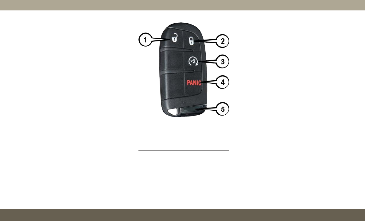
Key Fob
Your vehicle uses a keyless ignition system.
The ignition system consists of a key fob
with Remote Keyless Entry (RKE) and a
START/STOP push button ignition system.
The Remote Keyless Entry system consists of
a key fob and Keyless Enter-N-Go feature if
equipped.
NOTE:
The key fob may not be found if it is located
next to a mobile phone, laptop or other electronic device; these devices may block the
key fob’s wireless signal.
The key fob allows you to lock or unlock the
GETTING TO KNOW YOUR VEHICLE
doors and liftgate from distances up to approximately 66 ft (20 m) using a handheld
key fob. The key fob does not need to be
pointed at the vehicle to activate the system.
Keyless Ignition Key Fob
1 — Unlock 4 — Panic
2 — Lock 5 — Emergency
Key3 — Remote Start
The key fob also includes an emergency key,
which stores in the rear of the key fob.
The emergency key allows for entry into the
vehicle should the battery in the vehicle or
the key fob go dead. The emergency key is
also for locking the glove compartment. You
can keep the emergency key with you when
valet parking.
NOTE:
In case the ignition switch does not change
with the push of a button, the key fob may
have a low or fully depleted battery. A low key
fob battery can be verified by referring to the
instrument cluster, which will display directions to follow.
To remove the emergency key, slide the mechanical latch at the top of the key fob
sideways with your thumb and then pull the
key out with your other hand.
NOTE:
You can insert the double-sided emergency
key into the lock cylinders with either side
up.
12
Page 15
To Unlock The Doors And Liftgate
Push and release the unlock button on the
key fob once to unlock the driver's door or
twice within five seconds to unlock all doors
and the liftgate.
All doors can be programmed to unlock on the
first push of the unlock button. Refer to
“Uconnect Settings” in “Multimedia” in your
Owner’s Manual for further information.
To Lock The Doors And Liftgate
Push and release the lock button on the key
fob to lock all doors and liftgate.
Programming Additional Key Fobs
Programming the key fob may be performed
by an authorized dealer.
NOTE:
Once a key fob is programmed to a vehicle, it
cannot be repurposed and reprogrammed to
another vehicle.
Request For Additional Key Fobs
NOTE:
Only key fobs that are programmed to the
vehicle electronics can be used to start and
operate the vehicle. Once a key fob is programmed to a vehicle, it cannot be programmed to any other vehicle.
WARNING!
• Always remove the key fobs from the
vehicle and lock all doors when leaving
the vehicle unattended.
•
For vehicles equipped with Keyless EnterN-Go — Ignition, always remember to
place the ignition in the OFF mode.
Duplication of key fobs may be performed at
your authorized dealer. This procedure consists of programming a blank key fob to the
vehicle electronics. A blank key fob is one
that has never been programmed.
NOTE:
When having the Sentry Key Immobilizer System serviced, bring all vehicle keys with you
to your authorized dealer.
General Information
The following regulatory statement applies to
all radio frequency (RF) devices equipped in
this vehicle:
This device complies with Part 15 of the FCC
Rules and with Industry Canada licenseexempt RSS standard(s). Operation is subject to the following two conditions:
1. This device may not cause harmful interference, and
2. This device must accept any interference
received, including interference that may
cause undesired operation.
NOTE:
Changes or modifications not expressly approved by the party responsible for compliance could void the user’s authority to operate the equipment.
13
Page 16
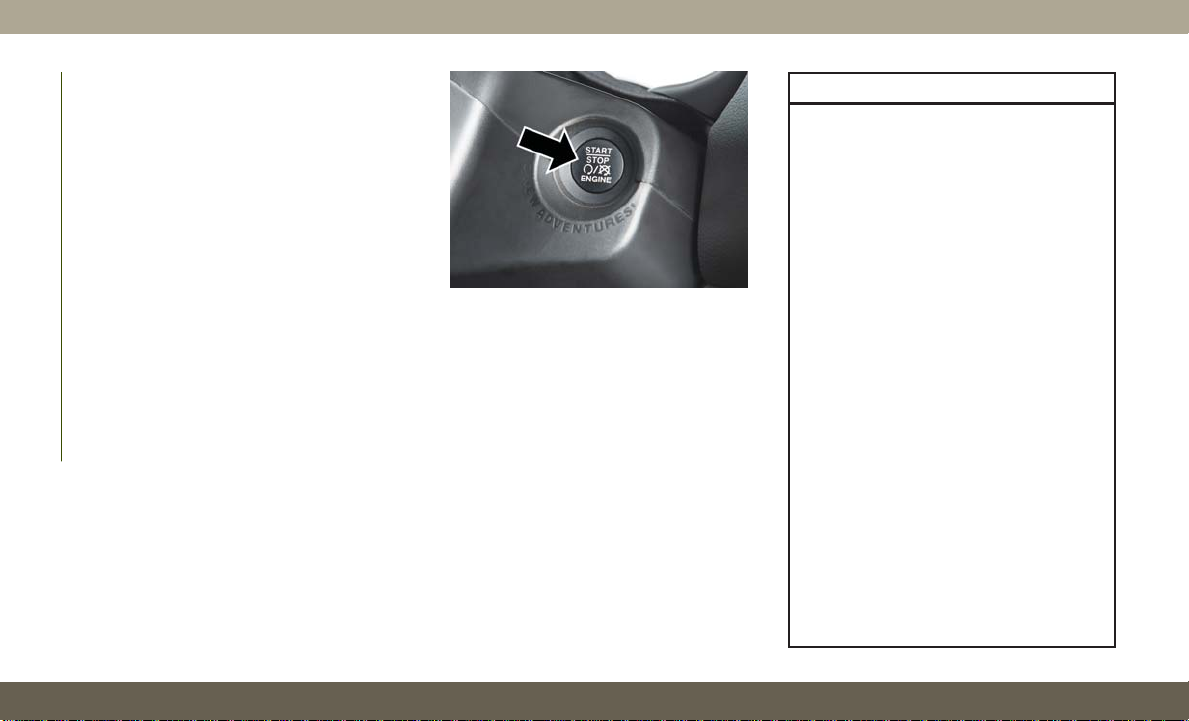
IGNITION SWITCH
Keyless Enter-N-Go — Ignition
This feature allows the driver to operate the
ignition with the push of a button as long as
the key fob is in the passenger compartment.
The START/STOP push button ignition has
three operating modes. The three modes are
OFF, ON/RUN, and START.
NOTE:
If the ignition state/mode does not change
with the push of a button, the key fob may
have a low or dead battery. In this situation, a
back up method can be used to operate the
ignition switch. Put the nose side (side opposite of the emergency key) of the key fob
GETTING TO KNOW YOUR VEHICLE
against the ENGINE START/STOP button and
push to operate the ignition.
START/STOP Ignition Button
The push button ignition can be placed in the
following modes:
OFF
• The engine is stopped.
• Some electrical devices (e.g. Central locking, alarm, etc.) are still available.
ON/RUN
• Driving mode.
• All the electrical devices are available.
START
• Start the engine.
WARNING!
• When exiting the vehicle, always remove
the key fob from the vehicle and lock
your vehicle.
• Never leave children alone in a vehicle,
or with access to an unlocked vehicle.
• Allowing children to be in a vehicle unattended is dangerous for a number of
reasons. A child or others could be seriously or fatally injured. Children should
be warned not to touch the parking
brake, brake pedal or the gear selector.
• Do not leave the key fob in or near the
vehicle, or in a location accessible to
children, and do not leave the ignition of
a vehicle equipped with Keyless EnterN-Go in the ON/RUN mode. A child
could operate power windows, other
controls, or move the vehicle.
• Do not leave children or animals inside
parked vehicles in hot weather. Interior
heat build-up may cause serious injury
or death.
• Never remove the mechanical key while
the vehicle is moving, as the steering
wheel will automatically lock as soon as
14
Page 17
WARNING!
the key is turned. This also applies to
vehicles that are being towed.
CAUTION!
An unlocked vehicle is an invitation for
thieves. Always remove key fob from the
vehicle and lock all doors when leaving the
vehicle unattended.
NOTE:
For further information, refer to "Starting The
Engine" in "Starting And Operating” in the
Owner’s Manual.
REMOTE STARTING SYSTEM — IF EQUIPPED
Push the remote start button on the key fob
twice within five seconds. Pushing the remote start button a third time shuts the
engine off.
To drive the vehicle, push the START/STOP
button to turn the ignition to the ON/RUN
mode.
NOTE:
• With remote start, the engine will only run
for 15 minutes (timeout) unless the ignition is placed in the ON/RUN mode.
• The vehicle must be started with the key
after two consecutive timeouts.
How To Use Remote Start — If Equipped
Push remote start button on
•
the key fob twice within five
seconds. Pushing the remote
start button a third time shuts
the engine off.
• To drive the vehicle, push unlock button,
insert the key in the ignition and turn to the
ON/RUN position.
• With remote start, the engine will only run
for 15 minutes (timeout) unless the ignition key is placed in the ON/RUN position.
• The vehicle must be started with the key
after two consecutive timeouts.
All of the following conditions must be met
before the engine will remote start:
• Gear selector in PARK
• Doors closed
• Hood closed
• Liftgate closed
• Hazard switch off
• Brake switch inactive (brake pedal not
pushed)
• Battery at an acceptable charge level
• Check engine light shall not be present
• PANIC button not pushed
• System not disabled from previous remote
start event
• Vehicle alarm system indicator flashing
• Ignition in STOP/OFF position
• Fuel level meets minimum requirement
• Vehicle security alarm is not signaling an
intrusion
15
Page 18

WARNING!
• Do not start or run an engine in a closed
garage or confined area. Exhaust gas
contains Carbon Monoxide (CO) which is
odorless and colorless. Carbon Monoxide is poisonous and can cause serious
injury or death when inhaled.
• Keep key fobs away from children. Operation of the Remote Start System, windows, door locks or other controls could
cause serious injury or death.
To Enter Remote Start Mode
Push and release the remote start button on
the key fob twice within five seconds. The
vehicle doors will lock, the parking lights will
GETTING TO KNOW YOUR VEHICLE
flash, and the horn will chirp twice (if programmed). Then, the engine will start, and
the vehicle will remain in the Remote Start
mode for a 15-minute cycle.
NOTE:
• If an engine fault is present or fuel level is
low, the vehicle will start and then shut
down in 10 seconds.
• The park lamps will turn on and remain on
during Remote Start mode.
• For security, power window and power sunroof operation (if equipped) are disabled
when the vehicle is in the Remote Start
mode.
• The engine can be started two consecutive
times with the key fob. However, the ignition must be cycled by pushing the START/
STOP button twice (or the ignition switch
must be cycled to the ON/RUN position)
before you can repeat the start sequence
for a third cycle.
General Information
The following regulatory statement applies to
all radio frequency (RF) devices equipped in
this vehicle:
This device complies with Part 15 of the FCC
Rules and with Industry Canada licenseexempt RSS standard(s). Operation is subject to the following two conditions:
1. This device may not cause harmful inter-
ference, and
2. This device must accept any interference
received, including interference that may
cause undesired operation.
NOTE:
Changes or modifications not expressly approved by the party responsible for compliance could void the user’s authority to operate the equipment.
VEHICLE SECURITY ALARM — IF EQUIPPED
The vehicle security alarm monitors the vehicle doors, hood, liftgate, and the Keyless
Enter-N-Go — Ignition for unauthorized operation. While the vehicle security alarm is
armed, interior switches for door locks and
liftgate release are disabled. If something
triggers the alarm, the vehicle security alarm
will provide the following audible and visible
signals:
• The horn will pulse
• The turn signals will flash
• The vehicle security light in the instrument
cluster will flash
16
Page 19

To Arm The System
Follow these steps to arm the vehicle security
alarm:
1. Make sure the vehicle’s ignition is placed
in the “OFF” mode.
2. Perform one of the following methods to
lock the vehicle:
• Push the lock button on the interior
power door lock switch with the driver
and/or passenger door open.
• Push the lock button on the key fob.
3. If any doors are open, close them.
To Disarm The System
The vehicle security alarm can be disarmed
using any of the following methods:
• Push the unlock button on the key fob.
• Cycle the ignition out of the off mode to
disarm the system.
NOTE:
• The driver's door key cylinder and the liftgate button on the key fob cannot arm or
disarm the vehicle security alarm.
• The vehicle security alarm remains armed
during power liftgate entry. Pushing the
liftgate button will not disarm the vehicle
security alarm. If someone enters the vehicle through the liftgate and opens any
door, the alarm will sound.
• When the vehicle security alarm is armed,
the interior power door lock switches will
not unlock the doors.
The vehicle security alarm is designed to
protect your vehicle. However, you can create
conditions where the system will give you a
false alarm. If one of the previously described
arming sequences has occurred, the vehicle
security alarm will arm regardless of whether
you are in the vehicle or not. If you remain in
the vehicle and open a door, the alarm will
sound. If this occurs, disarm the vehicle
security alarm.
If the vehicle security alarm is armed and the
battery becomes disconnected, the vehicle
security alarm will remain armed when the
battery is reconnected; the exterior lights will
flash, and the horn will sound. If this occurs,
disarm the vehicle security alarm.
Security System Manual Override
The vehicle security alarm will not arm if you
lock the doors using the manual door lock
plunger.
DOORS
Keyless Enter-N-Go — Passive Entry
The Passive Entry system is an enhancement
to the vehicle’s Remote Keyless Entry system
and a feature of Keyless Enter-N-Go — Passive Entry. This feature allows you to lock and
unlock the vehicle’s door(s) and fuel door
without having to push the key fob lock or
unlock buttons.
17
Page 20
NOTE:
• Passive Entry may be programmed ON/
OFF; refer to “Uconnect Settings” in “Multimedia” in the Owner’s Manual for further
information.
wearing gloves on your hands, or if it has
•If
been raining/snowing on the Passive Entry
door handle, the unlock sensitivity can be
affected, resulting in a slower response time.
• If the vehicle is unlocked by Passive Entry
and no door is opened within 60 seconds,
the vehicle will re-lock and if equipped will
arm the security alarm.
• The key fob may not be able to be detected
by the Passive Entry system if it is located
next to a mobile phone, laptop or other
electronic device; these devices may block
GETTING TO KNOW YOUR VEHICLE
the key fob’s wireless signal and prevent
the Passive Entry system from locking and
unlocking the vehicle.
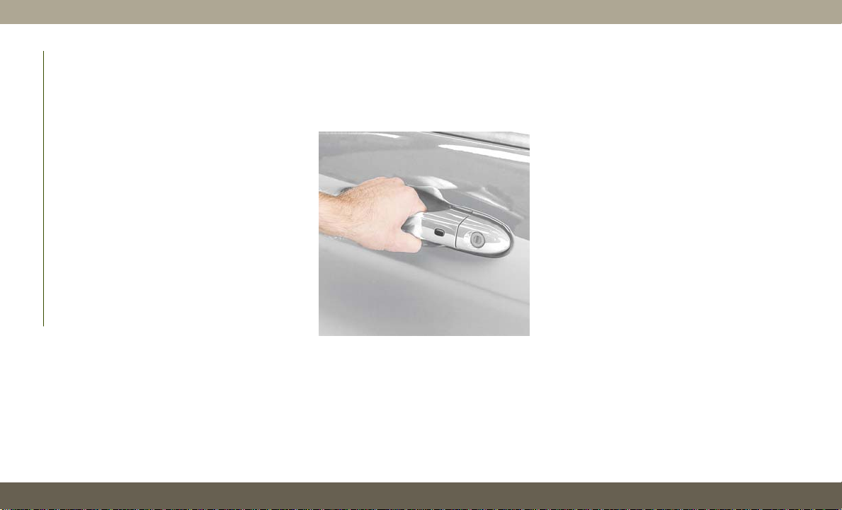
To Unlock From The Driver's Side
With a valid Passive Entry key fob within 5 ft
(1.5 m) of the driver's door handle, grab the
front driver door handle to unlock the driver's
door automatically.
Grab The Door Handle To Unlock
NOTE:
“Unlock All Doors 1st Press” is programmed,
If
all doors will unlock when you grab hold of the
front driver’s door handle. To select between
“Unlock Driver Door 1st Push” and “Unlock All
Doors 1st Press,” refer to “Uconnect Settings”
in “Multimedia” in the Owner’s manual for
further information.
To Unlock From The Passenger Side
With a valid Passive Entry key fob within 5 ft
(1.5 m) of the passenger door handle, grab
the front passenger door handle to unlock all
four doors and the liftgate automatically.
NOTE:
All doors will unlock when the front passenger door handle is grabbed regardless of
the driver’s door unlock preference setting
(“Unlock Driver Door 1st Press” or “Unlock
All Doors 1st Press”).
Preventing Inadvertent Locking Of Passive Entry
Key Fob In Vehicle (FOBIK-Safe)
To minimize the possibility of unintentionally
locking a Passive Entry key fob inside your
vehicle, the Passive Entry system is equipped
with an automatic door unlock feature which
will function if the ignition switch is in the
OFF position.
18
Page 21

FOBIK-Safe only executes in vehicles with
passive entry. There are three situations that
trigger a FOBIK-Safe search in any passive
entry vehicle:
• A lock request is made by a valid Passive
Entry key fob while a door is open.
• A lock request is made by the Passive Entry
door handle while a door is open.
• A lock request is made by the door panel
switch while the door is open.
When any of these situations occur, after all
open doors are shut, the FOBIK-Safe search
will be executed. If it finds a Passive Entry
key fob inside the car and it does not find any
Passive Entry key fobs outside the car, then
the car will unlock and alert the customer.
NOTE:
The vehicle will only unlock the doors when a
valid Passive Entry key fob is detected inside
the vehicle. The vehicle will not unlock the
doors when any of the following conditions
are true:
• The doors are manually locked using the
door lock knobs.
• There is a valid Passive Entry key fob outside the vehicle and within 5 ft (1.5m) of
either Passive Entry door handle.
• Three attempts are made to lock the doors
using the door panel switch and then close
the doors.
To Unlock/Enter The Liftgate
The liftgate passive entry unlock feature is
built into liftgate handle release. With a valid
Passive Entry key fob within 5 ft (1.5 m) of
the liftgate, push the electronic liftgate release to open with one fluid motion.
To Lock The Liftgate
With a valid Passive Entry key fob within 5 ft
(1.5 m) of the liftgate, push the passive entry
lock button located to the right of liftgate
handle release.
NOTE:
The liftgate passive entry lock button will lock
all doors and the liftgate. The liftgate unlock
feature is built into the electronic liftgate
release.
To Lock The Vehicle’s Doors And Liftgate
With one of the vehicle’s Passive Entry key
fob within 5 ft (1.5 m) of the driver or
passenger front door handles, push the passive entry lock button located on the outside
door handle, to lock the vehicle doors and
liftgate.
19
Page 22
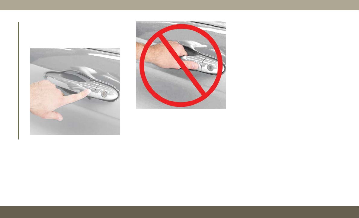
NOTE:
DO NOT grab the door handle, when pushing
the door handle lock button. This could unlock the door(s).
GETTING TO KNOW YOUR VEHICLE
Push The Door Handle Button To Lock
DO NOT Grab The Door Handle When
Locking
NOTE:
• After pushing the door handle button, you
must wait two seconds before you can lock
or unlock the doors, using either Passive
Entry door handle. This is done to allow you
to check if the vehicle is locked by pulling
the door handle without the vehicle reacting and unlocking.
• If Passive Entry is disabled using the
Uconnect System, the key protection described in "Preventing Inadvertent Locking
of Passive Entry key fob in Vehicle" remains
active/functional.
• The Passive Entry system will not operate if
the key fob battery is dead.
The vehicle doors can also be locked by using
the lock button located on the vehicle’s interior door panel.
General Information
The following regulatory statement applies to
all radio frequency (RF) devices equipped in
this vehicle:
This device complies with Part 15 of the FCC
Rules and with Industry Canada licenseexempt RSS standard(s). Operation is subject to the following two conditions:
1. This device may not cause harmful inter-
ference, and
2. This device must accept any interference
received, including interference that may
cause undesired operation.
20
Page 23
NOTE:
Changes or modifications not expressly approved by the party responsible for compliance could void the user’s authority to operate the equipment.
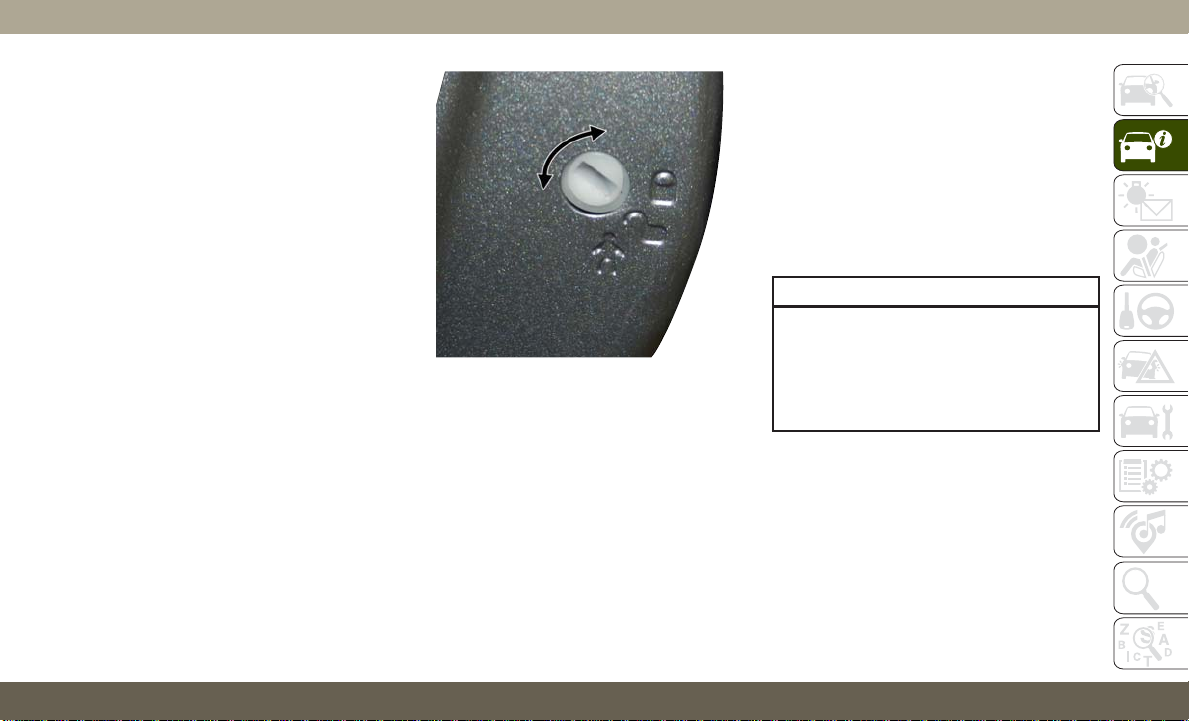
Child-Protection Door Lock System —
Rear Doors
To provide a safer environment for small children riding in the rear seats, the rear doors
are equipped with a Child-Protection Door
Lock system.
To use the system, open each rear door, use a
flat blade screwdriver (or emergency key) and
rotate the dial to the lock or unlock position.
When the system on a door is engaged, that
door can only be opened by using the outside
door handle even if the inside door lock is in
the unlocked position.
Child-Protection Door Lock Function
NOTE:
• When the child lock system is engaged, the
door can be opened only by using the outside door handle even though the inside
door lock is in the unlocked position.
• After disengaging the Child-Protection Door
Lock system, always test the door from the
inside to make certain it is in the desired
position.
• After engaging the Child-Protection Door
Lock system, always test the door from the
inside to make certain it is in the desired
position.
• For emergency exit with the system engaged, rotate the door lock button until the
lock indicator is hidden (unlocked position), roll down the window, and open the
door with the outside door handle.
WARNING!
Avoid trapping anyone in a vehicle in a
collision. Remember that the rear doors
can only be opened from the outside when
the Child-Protection locks are engaged
(locked).
21
Page 24
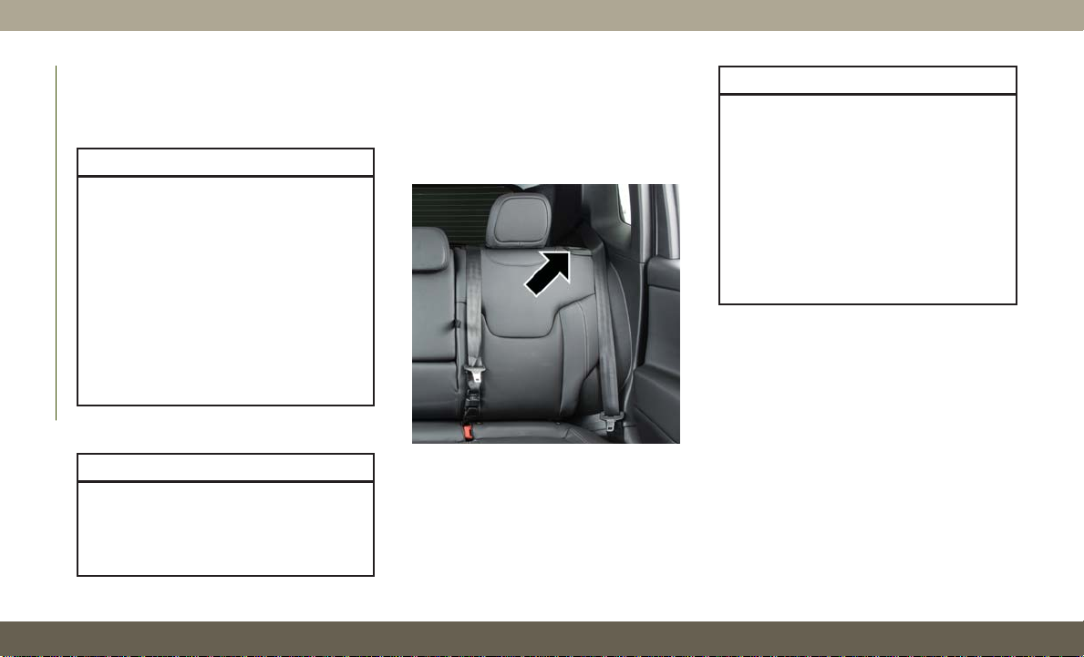
SEATS
Seats are a part of the Occupant Restraint
System of the vehicle.
WARNING!
•It
is dangerous to ride in a cargo area,
inside or outside of a vehicle. In a collision, people riding in these areas are more
likely to be seriously injured or killed.
• Do not allow people to ride in any area of
your vehicle that is not equipped with
seats and seat belts. In a collision,
people riding in these areas are more
likely to be seriously injured or killed.
• Be sure everyone in your vehicle is in a
seat and using a seat belt properly.
GETTING TO KNOW YOUR VEHICLE
Manual Adjustment (Rear Seats)
WARNING!
Do not pile luggage or cargo higher than
the top of the seatback. This could impair
visibility or become a dangerous projectile
in a sudden stop or collision.
22
60/40 Split Folding Rear Seat With Fold-Flat
Feature
To provide additional storage area, each rear
seat can be folded flat. This allows for extended cargo space and still maintains some
rear seating room.
Rear Seat Release Lever
NOTE:
Prior to folding the rear seat, it may be necessary to position the front seat to its mid-track
position. Also, be sure that the front seats are
fully upright and positioned forward. This will
allow the rear seat to fold down easily.
WARNING!
• It is extremely dangerous to ride in a
cargo area, inside or outside of a vehicle.
In a collision, people riding in these
areas are more likely to be seriously
injured or killed.
• Do not allow people to ride in any area of
your vehicle that is not equipped with
seats and seat belts.
• Be sure everyone in your vehicle is in a
seat and using a seat belt properly.
To Lower The Rear Seat
1. Pull the seatback release lever located on
either side of the upper outer edge of the
seat.
2. Fold that side of the rear seatback completely forward.
To Raise The Rear Seat
NOTE:
If
interference from the cargo area prevents the
seatback from fully locking, you will have difficulty returning the seat to its proper position.
Page 25
Raise the seatback and lock it into place.
The release lever will show a red indicator
while in the unlocked position. Once the seat
is locked in, the red indicator will no longer
be visible.
WARNING!
Be certain that the seatback is securely
locked into position. If the seatback is not
securely locked into position the seat will
not provide the proper stability for child
seats and/or passengers. An improperly
latched seat could cause serious injury.
Front Heated Seats — If Equipped
The front heated seats control buttons are
located within the Uconnect system. You can
gain access to the control buttons through
the climate screen or the controls screen.
• Press the heated seat button
turn the HI setting on.
• Press the heated seat button
time to turn the LO setting on.
• Press the heated seat button
time to turn the heating elements off.
once to
a second
a third
If your vehicle is equipped with automatic
temperature controls with an integrated center stack, or manual temperature controls,
you’ll find the heated seat switches on the
switch bank below the radio screen.
If the HI level setting is selected, the system
will automatically switch to LO level after
approximately 60 minutes of continuous operation. At that time, the display will change
from HI to LO, indicating the change. The LO
level setting will turn off automatically after
approximately 45 minutes.
NOTE:
The engine must be running for the heated
seats to operate.
Vehicles With Remote Start — If Equipped
On models that are equipped with remote
start, the heated seats can be programmed to
come on during a remote start.
This feature can be programmed through
the Uconnect system. Refer to “Uconnect
Settings” in “Multimedia” in the Owner’s
Manual for further information.
WARNING!
• Persons who are unable to feel pain to
the skin because of advanced age,
chronic illness, diabetes, spinal cord injury, medication, alcohol use, exhaustion or other physical condition must
exercise care when using the seat
heater. It may cause burns even at low
temperatures, especially if used for long
periods of time.
• Do not place anything on the seat or
seatback that insulates against heat,
such as a blanket or cushion. This may
cause the seat heater to overheat. Sitting in a seat that has been overheated
could cause serious burns due to the
increased surface temperature of the
seat.
23
Page 26
HEAD RESTRAINTS
Head restraints are designed to reduce the
risk of injury by restricting head movement in
the event of a rear impact. Head restraints
should be adjusted so that the top of the head
restraint is located above the top of your ear.
WARNING!
• All occupants, including the driver,
should not operate a vehicle or sit in a
vehicle’s seat until the head restraints
are placed in their proper positions in
order to minimize the risk of neck injury
in the event of a crash.
• Head restraints should never be adjusted while the vehicle is in motion.
Driving a vehicle with the head restraints
GETTING TO KNOW YOUR VEHICLE
improperly adjusted or removed could
cause serious injury or death in the
event of a collision.
NOTE:
Do not reverse the head restraints (making
the rear of the head restraint face forward) in
an attempt to gain additional clearance to the
back of your head.
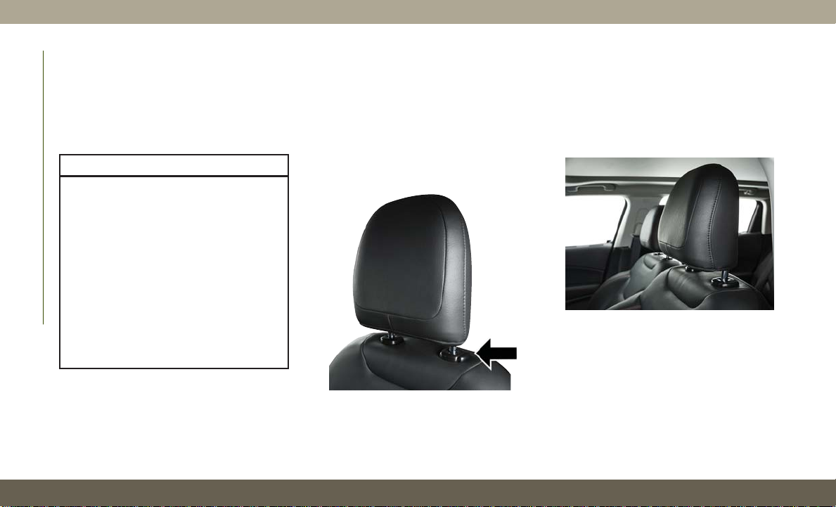
Front Head Restraint Adjustment
Your vehicle is equipped with front four way
driver and passenger head restraints.
To raise the head restraint, pull upward on
the head restraint. To lower the head restraint, push the adjustment button, located
at the base of the head restraint, and push
downward on the head restraint.
Head Restraint Adjustment Button
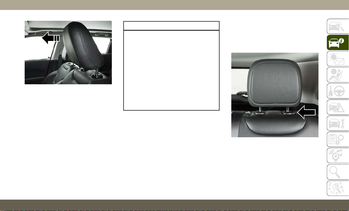
To adjust the head restraint forward, pull the
top of the head restraint toward the front of
the vehicle as desired and release. To adjust
the head restraint rearward, pull the top of
the head restraint to the forward most position and release. The head restraint will return to the rear most position.
Head Restraint (Normal Position)
24
Page 27
Head Restraint (Adjusted Position)
NOTE:
The head restraints should only be removed
by qualified technicians, for service purposes
only. If either of the head restraints require
removal, see an authorized dealer.
WARNING!
• All occupants, including the driver,
should not operate a vehicle or sit in a
vehicle’s seat until the head restraints
are placed in their proper positions in
order to minimize the risk of neck injury
in the event of a crash.
• Head restraints should never be adjusted while the vehicle is in motion.
Driving a vehicle with the head restraints
improperly adjusted or removed could
cause serious injury or death in the event
of a collision.
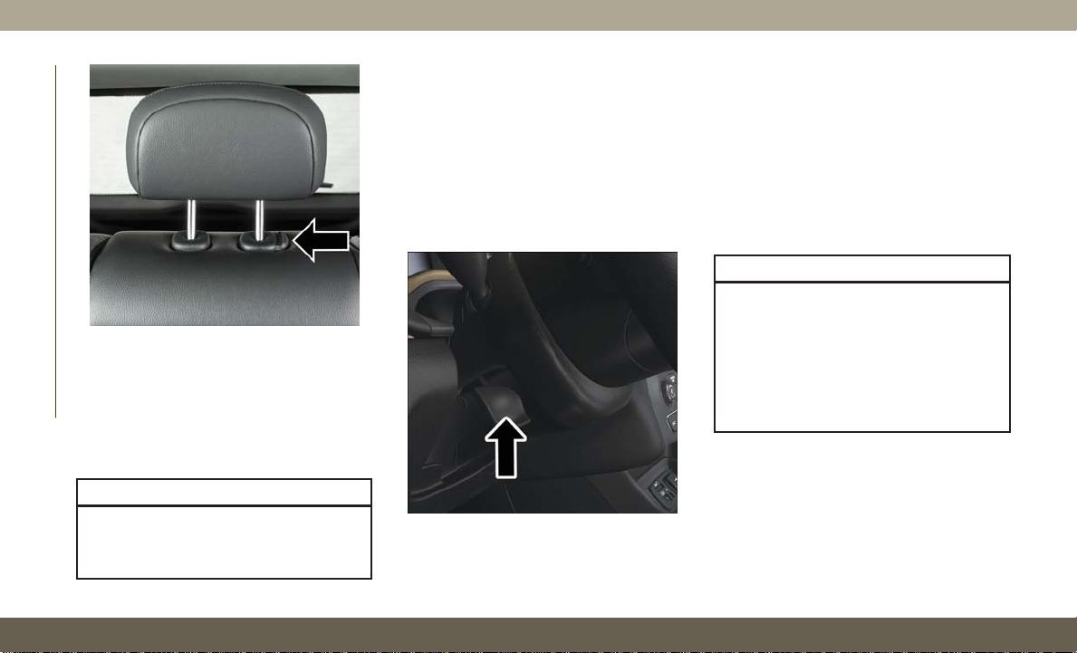
Rear Head Restraints
The rear head restraints have two positions:
up or down. When the center seat is being
occupied, the head restraint should be in the
raised position. When there is no occupant in
the center seat, the head restraint can be
lowered for maximum visibility for the driver.
To raise the head restraint, pull upward on the
head restraint. To lower the head restraint,
push the adjustment button, located at the
base of the head restraint, and push downward on the head restraint.
Outboard Head Restraint Adjustment
Button
25
Page 28
Center Head Restraint Adjustment Button
NOTE:
The head restraints should only be removed
GETTING TO KNOW YOUR VEHICLE
by qualified technicians, for service purposes
only. If either of the head restraints require
removal, see an authorized dealer.
WARNING!
ALL the head restraints MUST be reinstalled in the vehicle to properly protect
the occupants.
STEERING WHEEL
Tilt/Telescoping Steering Column
This feature allows you to tilt the steering
column upward or downward. It also allows
you to lengthen or shorten the steering column. The tilt/telescoping lever is located
below the steering wheel at the end of the
steering column.
Tilt/Telescoping Lever
To unlock the steering column, push the
control handle downward (toward the floor).
To tilt the steering column, move the steering
wheel upward or downward as desired. To
lengthen or shorten the steering column, pull
the steering wheel outward or push it inward
as desired. To lock the steering column in
position, push the control handle upward
until fully engaged.
WARNING!
Do not adjust the steering column while
driving. Adjusting the steering column
while driving or driving with the steering
column unlocked, could cause the driver
to lose control of the vehicle. Failure to
follow this warning may result in serious
injury or death.
26
Page 29
Heated Steering Wheel — If Equipped
The steering wheel contains a heating element that helps warm your hands in cold
weather. The heated steering wheel has only
one temperature setting. Once the heated
steering wheel has been turned on, it will stay
on until the operator turns it off. The heated
steering wheel may not turn on when it is
already warm.
The heated steering wheel control button is
located on the center instrument panel below
the touchscreen, as well as within the climate
or controls screen of the touchscreen.
• Press the heated steering wheel button
once to turn the heating element on.
• Press the heated steering wheel button
a second time to turn the heating element
off.
NOTE:
The engine must be running for the heated
steering wheel to operate.
Vehicles Equipped With Remote Start
On models that are equipped with remote
start, the heated steering wheel can be programmed to come on during a remote start.
This feature can be programmed through the
Uconnect system. Refer to “Uconnect Settings” in “Multimedia” in the Owner’s
Manual for further information.
WARNING!
• Persons who are unable to feel pain to
the skin because of advanced age,
chronic illness, diabetes, spinal cord injury, medication, alcohol use, exhaustion, or other physical conditions must
exercise care when using the steering
wheel heater. It may cause burns even at
low temperatures, especially if used for
long periods.
• Do not place anything on the steering
wheel that insulates against heat, such
as a blanket or steering wheel covers of
any type and material. This may cause
the steering wheel heater to overheat.
EXTERIOR LIGHTS
Multifunction Lever
The multifunction lever controls the operation of the turn signals, headlight beam selection and passing lights. The multifunction
lever is located on the left side of the steering
column.
Headlight Switch
The headlight switch is located on the left
side of the instrument panel. This switch
controls the operation of the headlights,
parking lights, automatic headlights — if
equipped, instrument panel lights, instrument panel light dimming, interior lights and
fog lights — if equipped.
27
Page 30
Daytime Running Lights (DRL) — If
Equipped
Automatic High Beam Headlamp Control —
If Equipped
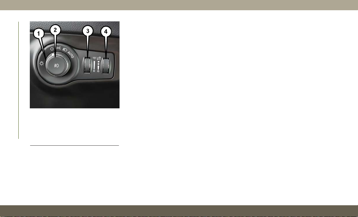
Headlight Switch
1 — Rotate Headlight
2 — Push Fog
3 — Ambient Light Dimmer
GETTING TO KNOW YOUR VEHICLE
4 — Instrument Panel Dimmer
Rotate the headlight switch clockwise to the
first detent for parking light and instrument
panel light operation. Rotate the headlight
switch to the second detent for headlight,
parking light and instrument panel light operation.
28
The Daytime Running Lights will turn on
when the engine is started and remain on
unless the headlamps are turned on or the
ignition is turned OFF.
NOTE:
If allowed by law in the country in which the
vehicle was purchased the Daytime Running
Lights can be turned on and off using the
Uconnect System. Refer to “Uconnect Settings” in “Multimedia” in the Owner’s
Manual for further details.
High/Low Beam Switch
Push the multifunction lever toward the instrument panel to switch the headlights to
high beams. Pulling the multifunction lever
back toward the steering wheel will return the
lights to low beams.
The Automatic High Beam Headlamp Control
system provides increased forward lighting at
night by automating high beam control
through the use of a digital camera mounted
on the inside rearview mirror. This camera
detects vehicle specific light and automatically switches from high beams to low beams
until the approaching vehicle is out of view.
NOTE:
• The Automatic High Beam Headlamp Control can be turned on or off using the
Uconnect System. Refer to “Uconnect Settings” in “Multimedia” in the Owner’s
Manual for further information.
• Broken, muddy, or obstructed headlights
and taillights of vehicles in the field of view
will cause headlights to remain on longer
(closer to the vehicle). Also, dirt, film, and
other obstructions on the windshield or
camera lens will cause the system to function improperly.
Page 31

• To opt out of the Advanced Auto High-Beam
Sensitivity Control (default) and enter Reduced High-Beam Sensitivity Control (not
recommended), toggle highbeam lever
6 full on/off cycles within 10 seconds of
ignition ON. System will return to default
setting upon ignition off.
Flash-To-Pass
You can signal another vehicle with your
headlights by lightly pulling the multifunction lever toward you. This will cause the high
beam headlights to turn on, and remain on,
until the lever is released.
Automatic Headlights — If Equipped
This system automatically turns the headlights on or off according to ambient light
levels. To turn the system on, rotate the
headlight switch clockwise to the last detent
for automatic headlight operation. When the
system is on, the headlight time delay feature
is also on. This means the headlights will stay
on for up to 90 seconds after you place the
ignition into the OFF position. To turn the
automatic system off, move the headlight
switch out of the AUTO position.
NOTE:
The engine must be running before the headlights will come on in the automatic mode.
Headlight Time Delay
This feature provides the safety of headlight
illumination for up to 90 seconds (programmable) when leaving your vehicle in an unlit
area.
To activate the delay feature, place the ignition in the OFF position while the headlights
are still on. Then, turn off the headlights
within 45 seconds. The delay interval begins
when the headlight switch is turned off.
If you turn the headlights or parking lights on,
or place the ignition in ACC or RUN, the
system will cancel the delay.
If
you turn the headlights off before the igni-
tion, they will turn off in the normal manner.
NOTE:
• The lights must be turned off within 45 seconds of placing the ignition in the OFF
position to activate this feature. If the
headlight switch is in the AUTO position
prior to turning the ignition OFF, there is no
need to turn the headlight switch to off to
activate Headlight Delay.
• The headlight delay time is programmable
using the Uconnect System. Refer to
“Uconnect Settings” in “Multimedia” in
the Owner’s Manual for further details.
Lights-On Reminder
If the headlights or parking lights are on after
the ignition is in the OFF position, a chime
will sound to alert the driver when the driver's
door is opened.
Fog Lights — If Equipped
The front fog light switch is built into the
headlight switch.
To activate the front fog lights, turn on the
parking lights or the low beam headlights and
push the headlight switch. To turn off the
front fog lights, either push the headlight
switch a second time or turn off the headlight
switch.
An indicator light in the instrument cluster
illuminates when the fog lights are turned on.
29
Page 32

NOTE:
The fog lights will operate with the low beam
headlights or parking lights on. However, selecting the high beam headlights will turn off
the fog lights.
Turn Signals
Move the multifunction lever up or down and
the arrows on each side of the instrument
cluster display flash to show proper operation
of the front and rear turn signal lights.
NOTE:
• If either light remains on and does not
flash, or there is a very fast flash rate, check
for a defective outside light bulb. If an
indicator fails to light when the lever is
moved, it would suggest that the indicator
GETTING TO KNOW YOUR VEHICLE
bulb is defective.
• A “Turn Signal On” message will appear in
the instrument cluster display and a continuous chime will sound if the vehicle is
driven more than 1 mile (1.6 km) with
either turn signal on.
• When the Daytime Running Lights are on
and a turn signal is activated, the Daytime
Running Lamp will turn off on the side of
the vehicle in which the turn signal is
flashing. The Daytime Running Lamp will
turn back on when the turn signal is turned
off.
Battery Saver Feature
To protect the battery, the interior lights will
turn off automatically 15 minutes after the
ignition switch is moved to the OFF/LOCK
position. This will occur if the interior lights
were switched on manually or are on because
a door is open.
WINDSHIELD WIPERS AND WASHERS
The windshield wiper/washer controls are located on the windshield wiper/washer lever
on the right side of the steering column. The
front wipers are operated by rotating a switch,
located on the end of the lever. For information on the rear wiper/washer, refer to “Rear
Window Wiper/Washer” in this section.
Windshield Wiper/Washer Lever
1 — Rear Wiper Operation
2 — Front Wiper Operation
Windshield Wiper Operation
Rotate the end of the lever to one of the first
two detent positions for intermittent settings.
The first intermittent wiper interval is 10 seconds. The second intermittent wipe interval
is based on vehicle speed. Rotate to the third
detent for low wiper operation and the fourth
detent for high wiper operation.
30
Page 33

CAUTION!
• Always remove any buildup of snow that
prevents the windshield wiper blades
from returning to the “park” position. If
the windshield wiper switch is turned
off, and the blades cannot return to the
“park” position, damage to the wiper
motor may occur.
• Failure to follow these cautions can
cause damage to the heating elements:
• Use care when washing the inside of
the rear window. Do not use abrasive window cleaners on the interior
surface of the window. Use a soft
cloth and a mild washing solution,
wiping parallel to the heating elements. Labels can be peeled off
after soaking with warm water.
•
Do not use scrapers, sharp instruments, or abrasive window cleaners
on the interior surface of the window.
• Keep all objects a safe distance
from the window.
Windshield Washer Operation
To use the washer, pull the lever toward you
and hold while spray is desired. If the lever is
pulled while in the intermittent setting, the
wipers will turn on and operate for several
wipe cycles after the lever is released, and
then resume the intermittent interval previously selected.
WARNING!
Sudden loss of visibility through the windshield could lead to a collision. You might
not see other vehicles or other obstacles.
To avoid sudden icing of the windshield
during freezing weather, warm the windshield with the defroster before and during
windshield washer use.
Mist
Push the lever upward to the MIST position
and release for a single wiping cycle.
NOTE:
T
he mist feature does not activate the washer
pump; therefore, no washer fluid will be
sprayed on the windshield. The wash function
must be used in order to spray the windshield
with washer fluid.
Rain Sensing Wipers — If Equipped
This feature senses rain or snow fall on the
windshield and automatically activates the
wipers for the driver. The feature is especially
useful for road splash or overspray from the
windshield washers of the vehicle ahead.
Rotate the end of the multifunction lever to
one of two settings to activate this feature.
The sensitivity of the system can be adjusted
with the multifunction lever. Wiper delay position one is the least sensitive, and wiper
delay position two is the most sensitive. Place
the wiper switch in the O (off) position when
not using the system.
NOTE:
• The Rain Sensing feature will not operate
when the wiper switch is in the low or
high-speed position.
• The Rain Sensing feature may not function
properly when ice, or dried salt water is
present on the windshield.
31
Page 34

• Use of Rain-X or products containing wax or
silicone may reduce Rain Sensing performance.
The Rain Sensing feature can be turned on
•
and off using the Uconnect System, refer to
“Uconnect Settings” in “Multimedia” in
your Owner’s Manual for further information.
The Rain Sensing system has protection features for the wiper blades and arms, and will
not operate under the following conditions:
• Change In Ignition Position — If the vehicle
is in Rain Sensing mode and the ignition is
cycled from OFF to ON, the auto wiper will
be suppressed until vehicle speed is greater
than 3 mph (5 km/h), or the wiper switch is
moved out of and back into the Intermittent
wipe position.
GETTING TO KNOW YOUR VEHICLE
• Transmission In NEUTRAL Position — The
Rain Sensing system will not operate if the
NEUTRAL gear is selected at speeds of
3 mph (5 km/h) or less unless the wiper
switch is moved or the gear selector is
moved out of NEUTRAL.
Remote Start Mode Inhibit — On vehicles
equipped with Remote Starting system, Rain
Sensing wipers are not operational when the
vehicle is in the remote start mode. Once the
operator is in the vehicle and has placed the
ignition switch in the ON/RUN position, Rain
Sensing wiper operation can resume, if it has
been selected, and no other inhibit conditions (mentioned previously) exist.
Rear Window Wiper/Washer
The rear wiper/washer controls are located on
the windshield wiper/washer lever on the
right side of the steering column. The rear
wiper/washer is operated by rotating a switch,
located at the middle of the lever.
Rotate the center portion of the lever upward
to the first detent for intermittent operation
and to the second detent for continuous rear
wiper operation.
To use the washer, push the lever forward and
hold while spray is desired. If the lever is
pushed while the wiper is in the off position,
the wiper will operate for several wipe cycles,
then turn off.
CLIMATE CONTROLS
The Climate Control System allows you to
regulate the temperature, air flow, and direction of air circulating throughout the vehicle.
The controls are located on the touchscreen
(if equipped) and on the instrument panel
below the radio.
Climate Controls With A Touchscreen
Overview
The controls for the heating and air conditioning system in this vehicle can consist of a
series of outer rotary dials, inner push knobs,
and/or a touchscreen. These comfort controls
can be set to obtain desired interior conditions.
32
Page 35

Uconnect 4 With 7-inch Display Automatic Climate Controls
33
Page 36

GETTING TO KNOW YOUR VEHICLE
34
Uconnect 4/4C NAV With 8.4-inch Display Automatic Climate Controls
Page 37

Climate Controls Description
Icon Description
Automatic Climate Controls Faceplate Buttons
MAX A/C Button
Press and release the MAX A/C button on the touchscreen to change the current setting to the coldest output of air.
Pressing the button again will cause the MAX A/C operation to exit.
NOTE:
The MAX A/C button is only available on the touchscreen.
35
Page 38

GETTING TO KNOW YOUR VEHICLE
Icon Description
A/C Button
Press and release to change the current setting, the indicator illuminates when A/C is ON.
Recirculation Button
Press and release this button to change the system between recirculation mode and outside air mode. Recirculation
can be used when outside conditions such as smoke, odors, dust, or high humidity are present. Recirculation can be
used in all modes. Recirculation may be unavailable (button on the touchscreen greyed out) if conditions exist that
could create fogging on the inside of the windshield. The A/C can be deselected manually without disturbing the
mode control selection. Continuous use of the Recirculation mode may make the inside air stuffy and window fogging may occur. Extended use of this mode is not recommended.
AUTO Button
Automatically controls the interior cabin temperature by adjusting airflow distribution and amount. Toggling this
function will cause the system to switch between manual mode and automatic modes. Refer to “Automatic Operation” within this section for more information.
Front Defrost Button
Press and release to change the current airflow setting to Defrost mode. The indicator illuminates when this feature
is on. Air comes from the windshield and side window demist outlets. When the defrost button is selected, the
blower level may increase. Use Defrost mode with maximum temperature settings for best windshield and side
window defrosting and defogging.
Performing this function will cause the ATC to switch into manual mode. If the front defrost mode is turned off the
climate system will return the previous setting.
Rear Defrost Button
Push and release the Rear Defrost Control button to turn ON the rear window defroster and the heated outside
mirrors (if equipped). An indicator will illuminate when the rear window defroster is on. The rear window defroster
automatically turns off after ten minutes.
36
Page 39

Icon Description
Driver and Passenger Temperature Up and Down Buttons
Provides the driver and passenger with independent temperature control. Push the red button on the faceplate or
touchscreen or press and slide the temperature bar towards the red arrow button on the touchscreen for warmer
temperature settings. Push the blue button on the faceplate or touchscreen or press and slide the temperature bar
towards the blue arrow button on the touchscreen for cooler temperature settings.
SYNC Button
Press the SYNC button on the touchscreen to toggle the Sync feature on/off. The SYNC indicator is illuminated
when this feature is enabled. SYNC is used to synchronize the passenger temperature setting with the driver temperature setting. Changing the passenger temperature setting while in SYNC will automatically exit this feature.
NOTE:
The SYNC button is only available on the touchscreen.
Faceplate Knobs
Blower Control
Blower Control is used to regulate the amount of air forced through the climate system. There are seven blower
MODE
speeds available. Adjusting the blower will cause automatic mode to switch to manual operation. The speeds can be
selected using either the blower control knob on the faceplate or the buttons on the touchscreen.
• Faceplate: The blower speed increases as you turn the blower control knob clockwise from the lowest blower setting.
Touchscreen Buttons
The blower speed decreases as you turn the blower control knob counterclockwise.
Touchscreen: Use the small blower icon to reduce the blower setting and the large blower icon to increase the blower
•
setting. Blower can also be selected by pressing the blower bar area between the icons.
Modes Button
Modes Button
Push the button in the center of the Blower Control Knob to change the airflow distribution mode. You can also
MODE
change the mode by pressing the desired mode on the touchscreen. The airflow distribution mode can be adjusted
so air comes from the instrument panel outlets, floor outlets, defrost outlets and demist outlets. The Mode settings
are as follows:
37
Page 40

Icon Description
Panel Mode
Bi-Level Mode
Floor Mode
Panel Mode
Air comes from the outlets in the instrument panel. Each of these outlets can be individually adjusted to direct the
flow of air. The air vanes of the center outlets and outboard outlets can be moved up and down or side to side to
regulate airflow direction. There is a shut off wheel located below the air vanes to shut off or adjust the amount of
airflow from these outlets.
Bi-Level Mode
Air comes from the instrument panel outlets and floor outlets. A slight amount of air is directed through the defrost
and side window demister outlets.
NOTE:
Bi-Level mode is designed under comfort conditions to provide cooler air out of the panel outlets and warmer air
from the floor outlets.
Floor Mode
Air comes from the floor outlets. A slight amount of air is directed through the defrost and side window demister
outlets.
GETTING TO KNOW YOUR VEHICLE
38
Mix Mode
Mix Mode
Air is directed through the floor, defrost, and side window demister outlets. This setting works best in cold or snowy
conditions that require extra heat to the windshield. This setting is good for maintaining comfort while reducing
moisture on the windshield.
Climate Control OFF Button
Press and release this button to turn the Climate Controls off or turn the Blower Control knob to the off position.
Page 41

Climate Control Functions
A/C (Air Conditioning)
The Air Conditioning (A/C) button allows the
operator to manually activate or deactivate
the air conditioning system. When the air
conditioning system is turned on, cool dehumidified air will flow through the outlets into
the cabin. For improved fuel economy, press
the A/C button to turn off the air conditioning
and manually adjust the blower and airflow
mode settings. Also, make sure to select only
Panel, Bi-Level, or Floor modes.
NOTE:
• For Manual Climate Controls, if the system
is in Mix, Floor or Defrost Mode, the A/C can
be turned off, but the A/C system shall
remain active to prevent fogging of the
windows.
• If fog or mist appears on the windshield or
side glass, select Defrost mode, and increase blower speed if needed.
• If your air conditioning performance seems
lower than expected, check the front of
the A/C condenser (located in front of the
radiator), for an accumulation of dirt or
insects. Clean with a gentle water spray
from the front of the radiator and through
the condenser.
MAX A/C
MAX A/C sets the control for maximum cooling performance.
Press and release to toggle between MAX A/C
and the prior settings. The button illuminates
when MAX A/C is on.
In MAX A/C, the blower level and mode position can be adjusted to desired user settings.
Pressing other settings will cause the MAX
A/C operation to switch to the selected setting and MAX A/C to exit.
Recirculation
In cold weather, use of Recirculation mode
may lead to excessive window fogging. The
Recirculation feature may be unavailable
(button on the touchscreen greyed out) if
conditions exist that could create fogging on
the inside of the windshield.
Automatic Temperature Control (ATC)
Automatic Operation
1. Push the AUTO button on the faceplate,
or the AUTO button on the touchscreen (if
equipped) on the Automatic Temperature
Control (ATC) Panel.
2. Next, adjust the temperature you would
like the system to maintain by adjusting
the temperature control buttons. Once the
desired temperature is displayed, the system achieves and automatically maintains
that comfort level.
3. When the system is set up for your comfort
level, it is not necessary to change the
settings. You experience the greatest efficiency by simply allowing the system to
function automatically.
NOTE:
• It is not necessary to move the temperature
settings for cold or hot vehicles. The system
automatically adjusts the temperature,
mode, and blower speed to provide comfort
as quickly as possible.
39
Page 42

• The temperature can be displayed in U.S.
or Metric units by selecting the US/Metric
customer-programmable feature.
To provide you with maximum comfort in the
Automatic mode during cold start-ups, the
blower fan remains on low until the engine
warms up. The blower increases in speed and
transition into Auto mode.
Manual Operation Override
This system offers a full complement of
manual override features. The AUTO symbol
in the front ATC display will be turned off
when the system is being used in the manual
mode.
Operating Tips
GETTING TO KNOW YOUR VEHICLE
Summer Operation
The engine cooling system must be protected
with a high-quality antifreeze coolant to provide proper corrosion protection and to protect against engine overheating. OAT coolant
(conforming to MS.90032) is recommended.
40
Winter Operation
To ensure the best possible heater and defroster performance, make sure the engine
cooling system is functioning properly and
the proper amount, type, and concentration
of coolant is used. Use of the Air Recirculation mode during Winter months is not recommended, because it may cause window
fogging.
Vacation/Storage
Before you store your vehicle, or keep it out of
service (i.e., vacation) for two weeks or more,
run the air conditioning system at idle for
about five minutes, in fresh air with the
blower setting on high. This will ensure adequate system lubrication to minimize the
possibility of compressor damage when the
system is started again.
Window Fogging
Vehicle windows tend to fog on the inside in
mild, rainy, and/or humid weather. To clear
the windows, select Defrost or Mix mode and
increase the front blower speed. Do not use
the Recirculation mode without A/C for long
periods, as fogging may occur.
CAUTION!
Failure to follow these cautions can cause
damage to the heating elements:
•
Use care when washing the inside of the
rear window. Do not use abrasive window
cleaners on the interior surface of the
window. Use a soft cloth and a mild
washing solution, wiping parallel to the
heating elements. Labels can be peeled
off after soaking with warm water.
• Do not use scrapers, sharp instruments, or abrasive window cleaners on
the interior surface of the window.
• Keep all objects a safe distance from
the window.
Outside Air Intake
Make sure the air intake, located directly in
front of the windshield, is free of obstructions, such as leaves. Leaves collected in the
air intake may reduce airflow, and if they
enter the plenum, they could plug the water
drains. In Winter months, make sure the air
intake is clear of ice, slush, and snow.
Page 43

Cabin Air Filter
The climate control system filters out dust
and pollen from the air. Contact an authorized dealer to service your cabin air filter,
and to have it replaced when needed.
WINDOWS
Power Window Controls
The window controls on the driver's door
control all the door windows.
Power Window Switches
There are single window controls on each
passenger door trim panel, which operate the
passenger door windows. The window controls will operate only when the ignition is in
the ACC or ON/RUN position.
NOTE:
For vehicles equipped with the Uconnect, the
power window switches will remain active for
up to ten minutes after the ignition is cycled
to the OFF position. Opening either front door
will cancel this feature. The time is programmable. Refer to “Uconnect Settings” in
“Multimedia” in the Owner’s Manual for further information.
WARNING!
Never leave children unattended in a vehicle. Do not leave the key fob in or near
the vehicle or in a location accessible to
children, and do not leave the ignition of a
vehicle equipped with Keyless Enter-N-Go
in the ACC or ON/RUN mode. Occupants,
WARNING!
particularly unattended children, can become entrapped by the windows while operating the power window switches. Such
entrapment may result in serious injury or
death.
Auto-Down Feature
The driver door power window switch and the
passenger door power window switches have
an Auto-Down feature. Push the window
switch down, for a short period of time, and
release and the window will go down automatically.
To open the window part way, push the window switch down briefly and release it when
you want the window to stop.
To stop the window from going all the way
down during the Auto-Down operation, pull
up on the switch briefly.
41
Page 44

Auto-Up Feature With Anti-Pinch
Protection
NOTE:
• If the window runs into any obstacle during
auto-closure, it will reverse direction and
then go back down. Remove the obstacle
and use the window switch again to close
the window.
• Any impact due to rough road conditions
may trigger the auto-reverse function unexpectedly during auto-closure. If this happens, pull the switch lightly and hold to
close the window manually.
WARNING!
There is no anti-pinch protection when the
GETTING TO KNOW YOUR VEHICLE
window is almost closed. To avoid personal
injury be sure to clear your arms, hands,
fingers and all objects from the window
path before closing.
Window Lockout Switch
The window lockout switch on the driver's
door trim panel allows you to disable the
window controls on the rear passenger doors.
To disable the window controls, push and
release the window lockout button (the indicator light on the button with turn on). To
enable the window controls, push and release
the window lockout button again (the indicator light on the button will turn back off).
Window Lockout Switch
Wind Buffeting
Wind buffeting can be described as the perception of pressure on the ears or a
helicopter-type sound in the ears. Your vehicle may exhibit wind buffeting with the
windows down, or the sunroof (if equipped) in
certain open or partially open positions. This
is a normal occurrence and can be minimized. If the buffeting occurs with the rear
windows open, open the front and rear windows together to minimize the buffeting. If
the buffeting occurs with the sunroof open,
adjust the sunroof opening to minimize the
buffeting or open any window.
42
Page 45

POWER SUNROOF WITH POWER SHADE — IF EQUIPPED
The power sunroof switches are located between the sun visors on the overhead console.
Power Sunroof Switches
1 — Power Shade Switch
2 — Front Panel Open/Close Switch
3 — Front Panel Vent Switch
WARNING!
• Never leave children unattended in a
vehicle, or with access to an unlocked
vehicle. Never leave the key fob in or
near the vehicle, or in a location accessible to children. Do not leave the ignition of a vehicle equipped with Keyless
Enter-N-Go in the ON/RUN mode. Occupants, particularly unattended children,
can become entrapped by the power
sunroof while operating the power sunroof switch. Such entrapment may result
in serious injury or death.
• In a collision, there is a greater risk of
being thrown from a vehicle with an
open sunroof. You could also be seriously injured or killed. Always fasten
your seat belt properly and make sure all
passengers are also properly secured.
• Do not allow small children to operate
the sunroof. Never allow your fingers,
other body parts, or any object, to project through the sunroof opening. Injury
may result.
Opening Sunroof
The sunroof has two programmed open positions, comfort stop position and full open
position. The comfort stop position has been
optimized to minimize wind buffeting when
driving with side windows closed and sunroof
open. If the sunshade is in the closed position when initiating a sunroof open or vent
command the sunshade will automatically
open to the half open position prior to the
sunroof opening.
Express
Push the switch and release it within one-half
second, the sunroof will open to the comfort
stop position and automatically stop. Push
the switch and release it again, the sunroof
will open to the full open position and automatically stop. This is called “Express
Open”. During Express Open operation, any
movement of the sunroof switch will stop the
sunroof.
43
Page 46

Manual Mode
Push and hold the switch, the sunroof will
open to the comfort stop position and automatically stop. Push the switch and hold it
again, the sunroof will open to the full open
position and automatically stop. Any release
of the switch will stop the sunroof movement.
The sunroof will remain in a partially opened
condition until the switch is pushed and held
again.
Opening Sunroof — Vent
Push and release the "Vent" button within
one-half second and the sunroof will move
from the closed position to the vent position.
This is called “Express Vent.” During Express
Vent operation, any movement of the switch
GETTING TO KNOW YOUR VEHICLE
will stop the sunroof.
NOTE:
When the sunroof is in a full open or a partial
open position, Express Vent operation is not
available. You must push and hold the vent
switch to cycle the sunroof from a slide open
position to the vent position. Sunroof movement will stop if the switch is released prior
to the sunroof reaching the vent position.
44
Closing Sunroof
Express
Pull the switch down and release it within
one-half second and the sunroof will close
automatically from any position. The sunroof
will close fully and stop automatically. This is
called “Express Close”. During Express Close
operation, any other actuation of the switch
will stop the sunroof.
Manual Mode
Pull and hold the switch down and the sunroof
will close from any position. Any release of the
switch will stop the movement and the sunroof
will remain in a partially closed condition until
the sunroof switch is pulled again.
Opening Power Shade
The sunshade has two programmed open
positions: half open and full open positions.
When opening the sunshade from the closed
position, the sunshade will always stop at the
half open position regardless of express or
manual open operation. The switch must be
actuated again to continue on to full open
position.
Express
Push the sunshade switch and release it
within one-half second, the sunshade will
open to the half open position and stop automatically. Push and release the switch again
from the half open position and the sunshade
will open to the full open position and stop
automatically. This is called “Express Open”.
During Express Open operation, any movement of the sunshade switch will stop the
shade.
Manual Mode
Push and hold the sunshade switch, the
sunshade will open to the half open position
and stop automatically. Push and hold the
sunshade switch again and the sunshade will
open to the full open position. Any release of
the switch will stop the movement and the
sunshade will remain in a partially opened
condition until the switch is pushed again.
Page 47

Closing Power Shade
If the sunroof is open/vented, the sunshade
cannot be closed beyond the half open position. Pulling the sunshade close switch when
sunshade is at half open position with sunroof open/vented will automatically close
sunroof prior to the sunshade closing.
Express
Pull the sunshade switch down and release it
within one-half second. If the sunroof is in
closed position, the sunshade will full close
automatically from any position. If the sunroof is open or vented, the sunshade will
close to the half open position and stop; pull
and release the sunshade switch again to
automatically close both the sunroof and sunshade completely. This is called “Express
Close”. During Express Close operation, any
movement of the switch will stop the sunshade.
Manual
Pull and hold the sunshade switch down. If
the sunroof is in closed position, the sunshade will fully close from any position. If the
sunroof is open or vented, the sunshade will
close to the half open position and stop;
pulling and holding the sunshade switch
again will close both the sunroof and sunshade completely. Any release of the switch
will stop the movement and the sunshade will
remain in a partially closed condition until
the switch is pulled again.
Pinch Protect Feature
This feature will detect an obstruction in the
opening of the sunroof during Express Close
operation. If an obstruction in the path of the
sunroof is detected, the sunroof will automatically retract. Remove the obstruction if
this occurs. Next, pull the sunroof close
switch and release to Express Close.
NOTE:
If three consecutive sunroof close attempts
result in Pinch Protect reversals, Pinch Protect will disable and the sunroof must be
closed in Manual Mode.
Sunroof Maintenance
Use only a non-abrasive cleaner and a soft
cloth to clean the glass panel.
Ignition Off Operation
The power sunroof switch will remain active
for up to approximately ten minutes after the
ignition is turned OFF. Opening either front
door will cancel this feature.
NOTE:
Ignition Off time is programmable through
the Uconnect System. Refer to “Uconnect
Settings/Customer Programmable Features”
in “Multimedia” in your Owner’s Manual for
further information.
45
Page 48

HOOD
Opening The Hood
Two latches must be released to open the hood.
1. Pull the hood release lever located underneath the driver’s side of the instrument
panel.
GETTING TO KNOW YOUR VEHICLE
2. Move to the outside of the vehicle. The
safety latch release lever is located behind the front edge of the hood at the
center. Reach in at the center of the hood
with a palm facing the ground. Once contact is made with the safety latch release
lever, push it toward the passenger side of
the vehicle to fully release the hood.
Hood Safety Latch Release Lever Location
Closing The Hood
WARNING!
Be sure the hood is fully latched before
driving your vehicle. If the hood is not fully
latched, it could open when the vehicle is
in motion and block your vision. Failure to
follow this warning could result in serious
injury or death.
CAUTION!
To prevent possible damage, do not slam
the hood to close it. Lower hood to approximately 12 inches (30 cm) and drop the
hood to close. Make sure hood is fully
closed for both latches. Never drive vehicle unless hood is fully closed, with both
latches engaged.
Hood Release Location (Underneath
Instrument Panel)
46
Page 49

LIFTGATE
Opening
To Unlock/Enter The Liftgate
The liftgate may be released by the overhead
console switch, the outside handle, or the key
fob (if equipped).
The overhead console switch and key fob (if
equipped) will release the liftgate when the
liftgate is unlocked or locked. The outside
handle requires the liftgate to be unlocked.
Liftgate Entry
NOTE:
Use the interior door lock/unlock button on
the door panel or the key fob to lock and
unlock the liftgate. The manual door locks on
the doors and the exterior door lock cylinder
will not lock and unlock the liftgate.
WARNING!
Driving with the liftgate open can allow
poisonous exhaust gases into your vehicle.
You and your passengers could be injured
by these fumes. Keep the liftgate closed
when you are operating the vehicle.
Closing
Grasp the liftgate pull handle and initiate lowering the liftgate. Release the handle when the
liftgate reaches the self-closing position.
NOTE:
Before closing the liftgate, make sure to be in
possession of the key because the liftgate
may be locked.
Power Liftgate — If Equipped
The power liftgate may be opened or
closed by the key fob, outside handle, overhead
console switch, and the liftgate switch on the
upper left trim when the liftgate is open.
Using any of the above ways:
• When the liftgate is fully closed, the liftgate
will open.
• When the liftgate is fully open, the liftgate
will close.
• When the liftgate is moving, the liftgate will
reverse.
The key fob and the overhead console switch
will open the liftgate when the liftgate is
locked. The outside handle requires the liftgate to be unlocked. Push the button on the
key fob twice within five seconds to open or
close the liftgate.
When the liftgate button on the key fob is
pushed two times, the turn signals will flash
twice to signal that the liftgate is opening or
47
Page 50

closing (if Flash Lamps with Lock is enabled
in the Uconnect settings), and the liftgate
chime will be audible. Refer to “Uconnect
Settings” in “Multimedia” in your Owner’s
Manual for further information.
NOTE:
• Before closing the liftgate, make sure to be
in possession of the key because the liftgate may be locked.
Use the interior door lock/unlock button on
•
the door panel or the key fob to lock and
unlock the liftgate. The manual door locks on
the doors and the exterior door lock cylinder
will not lock and unlock the liftgate.
Lock The Vehicle
GETTING TO KNOW YOUR VEHICLE
During power operation, personal injury or
cargo damage may occur. Ensure the liftgate travel path is clear. Make sure the
liftgate is closed and latched before driving away.
WARNING!
48
NOTE:
• The liftgate will not power open or close if
the gear selector is in gear or the vehicle
speed is above 0 mph (0 km/h).
• If anything obstructs the power liftgate
while it is closing or opening, the liftgate
will automatically reverse to the closed or
open position, provided it meets sufficient
resistance.
• There are pinch sensors attached to the
side of the liftgate opening. Light pressure
anywhere along these strips will cause the
liftgate to return to the open position.
• If the power liftgate encounters multiple
obstructions within the same cycle, the
system will automatically stop. If this occurs, the liftgate must be opened or closed
manually.
• The power liftgate will not operate in temperatures below −22° F (−30° C) or temperatures above 150° F (65° C). Be sure to
remove any buildup of snow or ice from the
liftgate before pushing any of the power
liftgate switches.
• If the liftgate is left open for an extended
period of time, the liftgate may need to be
closed manually to reset power liftgate
functionality.
• Gas props support the liftgate in the open
position. However, because the gas pressure drops with temperature, it may be
necessary to assist the props when opening
the liftgate in cold weather.
• Before driving off, check the instrument
cluster for a liftgate or door open message
or warning indicator. Failure to do this
could result in unintentionally leaving the
liftgate open while driving.
• If your liftgate is power closing and you put
the vehicle in gear, the liftgate will continue to power close. However, vehicle
movement may result in a detection of an
obstruction.
• If the electronic liftgate release handle is
pushed with the power liftgate is opening,
the liftgate motor will disengage to allow
manual operation.
the electronic liftgate release handle is
•If
pushed while the power liftgate is closing, the
liftgate will reverse to the full open position.
Page 51

WARNING!
•
Driving with the liftgate open can allow
poisonous exhaust gases into your vehicle. You and your passengers could be
injured by these fumes. Keep the liftgate
closed when you are operating the vehicle.
• If you are required to drive with the
liftgate open, make sure that all windows are closed, and the climate control
blower switch is set at high speed. Do
not use the recirculation mode.
NOTE:
Allow the power system to open the liftgate.
Manually pushing or pulling the liftgate may
activate the liftgate obstacle detection feature and stop the power operation or reverse
its direction.
WARNING!
Personal injury or cargo damage may occur
if caught in the path of the liftgate. Make
sure the liftgate path is clear before activating the liftgate.
INTERNAL EQUIPMENT
Power Outlets
Your vehicle is equipped with 12 Volt
(13 Amp) power outlets that can be used to
power cellular phones, small electronics and
other low powered electrical accessories. The
power outlets are labeled with either a “key”
or a “battery” symbol to indicate how the
outlet is powered. Power outlets labeled with
a “key” are powered when the ignition is in
the ON or ACC position, while the outlets
labeled with a “battery” are connected directly to the battery and powered at all times.
NOTE:
• All accessories connected to the “battery”
powered outlets should be removed or
turned off when the vehicle is not in use to
protect the battery against discharge.
CAUTION!
Power outlets are designed for accessory
plugs only. Do not insert any other object
in the power outlets as this will damage
CAUTION!
the outlet and blow the fuse. Improper use
of the power outlet can cause damage not
covered by your New Vehicle Limited Warranty.
The front power outlet is located on the center stack of the instrument panel.
Front Power Outlet
49
Page 52

In addition to the front power outlet, there is
also a power outlet located in the rear cargo
area.
WARNING!
To avoid serious injury or death:
• Only devices designed for use in this
type of outlet should be inserted into any
12 Volt outlet.
• Do not touch with wet hands.
• Close the lid when not in use and while
driving the vehicle.
• If this outlet is mishandled, it may cause
an electric shock and failure.
CAUTION!
Only use these intermittently and with
greater caution.
• After the use of high power draw accessories, or long periods of the vehicle not
being started (with accessories still
plugged in), the vehicle must be driven
a sufficient length of time to allow
the generator to recharge the vehicle's
battery.
GETTING TO KNOW YOUR VEHICLE
Rear Cargo Area Power Outlet
NOTE:
The rear cargo area power outlet can be
switched from “ignition” only to constant
“battery” powered all the time. See an authorized dealer for details.
50
CAUTION!
• Many accessories that can be plugged in
draw power from the vehicle's battery,
even when not in use (i.e., cellular
phones, etc.). Eventually, if plugged in
long enough, the vehicle's battery will
discharge sufficiently to degrade battery
life and/or prevent the engine from starting.
•
Accessories that draw higher power (i.e.,
coolers, vacuum cleaners, lights, etc.) will
degrade the battery even more quickly.
Power Inverter — If Equipped
Power Inverter Location
Page 53

There is a 115 Volt, 150 Watt inverter outlet
located on the back of the center console to
convert DC current to AC current. This outlet
can power cellular phones, electronics and
other low power devices requiring power up to
150 Watts. Certain high-end game consoles
will exceed this power limit, as will most
power tools.
To turn on the power inverter outlet, simply
plug in the device. The outlet automatically
turns off when the device is unplugged.
The power inverter is designed with built-in
overload protection. If the power rating of
150 Watts is exceeded, the power inverter
will automatically shut down. Once the electrical device has been removed from the outlet the inverter should automatically reset. To
avoid overloading the circuit, check the
power ratings on electrical devices prior to
using the inverter.
WARNING!
To avoid serious injury or death:
•
Do not insert any objects into the receptacles.
• Do not touch with wet hands.
• Close the lid when not in use.
• If this outlet is mishandled, it may
cause an electric shock and failure.
ROOF LUGGAGE RACK — IF EQUIPPED
The load carried on the roof, when equipped
with a luggage rack, must not exceed 150 lbs
(68 kg), and it should be uniformly distributed over the cargo area.
Crossbars should always be used whenever
cargo is placed on the roof rack. Check the
straps frequently to be sure that the load
remains securely attached.
NOTE:
Crossbars can be purchased at your authorized dealer through Mopar parts.
External racks do not increase the total load
carrying capacity of the vehicle. Be sure that
the total occupant and luggage load inside
the vehicle, plus the load on the luggage rack,
do not exceed the maximum vehicle load
capacity.
WARNING!
Cargo must be securely tied down before
driving your vehicle. Improperly secured
loads can fly off the vehicle, particularly at
high speeds, resulting in personal injury or
property damage. Follow the roof rack cautions when carrying cargo on your roof rack.
CAUTION!
• To avoid damage to the roof rack and
vehicle, do not exceed the maximum
roof rack load capacity. Always distribute heavy loads as evenly as possible
and secure the load appropriately.
• Long loads, which extend over the windshield, should be secured to both the
front and rear of the vehicle.
51
Page 54

CAUTION!
•
Place a blanket or other protection between the surface of the roof and the load.
• Travel at reduced speeds and turn corners carefully when carrying large or
heavy loads on the roof rack. Wind
forces, due to natural causes or nearby
truck traffic, can add sudden upward
loads. It is recommended to not carry
large flat loads, such as wood panels or
surfboards, which may result in damage
to the cargo or your vehicle.
• Load should always be secured to cross
bars first, with tie down loops used as
additional securing points if needed. Tie
loops are intended as supplementary tie
down points only. Do not use ratcheting
mechanisms with the tie loops. Check
GETTING TO KNOW YOUR VEHICLE
the straps frequently to be sure that the
load remains securely attached.
52
Page 55

INSTRUMENT CLUSTER DISPLAY
Your vehicle may be equipped with an instrument cluster display, which offers useful information to the driver. With the ignition in
the STOP/OFF mode, opening/closing of a
door will activate the display for viewing, and
display the total miles, or kilometers, in the
odometer. Your instrument cluster display is
designed to display important information
about your vehicle’s systems and features.
Using a driver interactive display located on
the instrument panel, your instrument cluster
display can show you how systems are working and give you warnings when they aren’t.
The steering wheel mounted controls allow
you to scroll through and enter the main
menus and submenus. You can access the
specific information you want and make selections and adjustments.
Instrument Cluster Display Location And
Controls
The instrument cluster display features a
driver-interactive display that is located in
the instrument cluster.
Instrument Cluster Display Location
The instrument cluster display menu items
consist of the following as equipped:
• Speedometer
• Vehicle Info
• Driver Assist
• Fuel Economy
• Trip
• Stop/Start (If Equipped)
• Audio
• Messages
• Screen Setup
• Vehicle Settings
The systems allow the driver to select information by pushing the following buttons
mounted on the steering wheel:
Instrument Cluster Display Control Buttons
53
Page 56

• Up Arrow Button
Push and release the up arrow button to
scroll upward through the main menu and
submenus.
• Down Arrow Button
Push and release the down arrow button to
scroll downward through the main menu
and submenus.
• Right Arrow Button
Push and release the right arrow button to
access the information screens or submenu
screens of a main menu item.
• Left Arrow Button
Push and release the left arrow button to
access the information screens or submenu
screens of a main menu item.
• OK Button
Push the OK button to access/select the
information screens or submenu screens of
a main menu item. Push and hold the OK
button for one second to reset displayed/
selected features that can be reset.
GETTING TO KNOW YOUR INSTRUMENT PANEL
Oil Change Reset
• Your vehicle is equipped with an engine oil
change indicator system. The “Oil Change
Due” message will display in the instrument cluster display for five seconds after a
single chime has sounded, to indicate the
next scheduled oil change interval. The
engine oil change indicator system is duty
cycle based, which means the engine oil
change interval may fluctuate, dependent
upon your personal driving style.
• Unless reset, this message will continue to
display each time the ignition is cycled to
the ON/RUN position.
To reset the oil change indicator after performing the scheduled maintenance, refer to
the following procedure:
1. Without pressing the brake pedal, push
the ENGINE START/STOP button and
cycle the ignition to the ON/RUN position
(do not start the engine).
2. Fully press the accelerator pedal, slowly,
three times within ten seconds.
Cycle the ignition to the OFF/LOCK position.
3.
NOTE:
If the indicator message illuminates when
you start the vehicle, the oil change indicator
system did not reset. If necessary, repeat this
procedure.
Instrument Cluster Display Menu Items
NOTE:
The instrument cluster display menu items
display in the center of the instrument cluster. Menu items may vary depending on your
vehicle features.
TRIP COMPUTER
Push and release the up or down arrow button
until the Trip A or Trip B icon is highlighted in
the instrument cluster display (Toggle left or
right to select Trip A or Trip B). Push and
release the OK button to display the Trip
information.
54
Page 57

WARNING LIGHTS AND MESSAGES
The warning/indicator lights will illuminate in
the instrument panel together with a dedicated message and/or acoustic signal when
applicable. These indications are indicative
and precautionary and as such must not be
considered as exhaustive and/or alternative
to the information contained in the Owner’s
Manual, which you are advised to read carefully in all cases. Always refer to the information in this chapter in the event of a failure
indication. All active telltales will display first
if applicable. The system check menu may
appear different based upon equipment options and current vehicle status. Some telltales are optional and may not appear.
Red Warning Lights
— Air Bag Warning Light
This warning light will illuminate to indicate a
fault with the air bag, and will turn on for four
to eight seconds as a bulb check when the
ignition is placed in the ON/RUN or ACC/ON/
RUN position. This light will illuminate with a
single chime when a fault with the air bag has
been detected, it will stay on until the fault is
cleared. If the light is either not on during
startup, stays on, or turns on while driving,
have the system inspected at an authorized
dealer as soon as possible.
— Brake Warning Light
This warning light monitors various brake
functions, including brake fluid level and
parking brake application. If the brake light
turns on it may indicate that the parking
brake is applied, that the brake fluid level is
low, or that there is a problem with the
anti-lock brake system reservoir.
If the light remains on when the parking
brake has been disengaged, and the fluid
level is at the full mark on the master cylinder
reservoir, it indicates a possible brake hydraulic system malfunction or that a problem
with the Brake Booster has been detected by
the Anti-Lock Brake System (ABS) / Electronic Stability Control (ESC) system. In this
case, the light will remain on until the condition has been corrected. If the problem is
related to the brake booster, the ABS pump
will run when applying the brake, and a brake
pedal pulsation may be felt during each stop.
The dual brake system provides a reserve
braking capacity in the event of a failure to a
portion of the hydraulic system. A leak in
either half of the dual brake system is indicated by the Brake Warning Light, which will
turn on when the brake fluid level in the
master cylinder has dropped below a specified level.
The light will remain on until the cause is
corrected.
NOTE:
The light may flash momentarily during sharp
cornering maneuvers, which change fluid
level conditions. The vehicle should have
service performed, and the brake fluid level
checked.
If brake failure is indicated, immediate repair
is necessary.
55
Page 58

WARNING!
Driving a vehicle with the red brake light
on is dangerous. Part of the brake system
may have failed. It will take longer to stop
the vehicle. You could have a collision.
Have the vehicle checked immediately.
Vehicles equipped with the Anti-Lock Brake
System (ABS) are also equipped with Electronic Brake Force Distribution (EBD). In the
event of an EBD failure, the Brake Warning
Light will turn on along with the ABS Light.
Immediate repair to the ABS system is required.
Operation of the Brake Warning Light can be
checked by turning the ignition switch from
the OFF position to the ON/RUN position.
The light should illuminate for approximately
two seconds. The light should then turn off
unless the parking brake is applied or a brake
fault is detected. If the light does not illuminate, have the light inspected by an authorized dealer.
GETTING TO KNOW YOUR INSTRUMENT PANEL
56
The light also will turn on when the parking
brake is applied with the ignition switch in
the ON/RUN position.
NOTE:
This light shows only that the parking brake is
applied. It does not show the degree of brake
application.
— Battery Charge Warning Light
This warning light will illuminate when the
battery is not charging properly. If it stays on
while the engine is running, there may be a
malfunction with the charging system. Contact an authorized dealer as soon as possible.
This indicates a possible problem with the
electrical system or a related component.
— Door Open Warning Light
This indicator will illuminate when a door is
ajar/open and not fully closed.
NOTE:
If the vehicle is moving, there will also be a
single chime.
— Electric Power Steering Fault
Warning Light
This warning light will turn on when there's a
fault with the EPS (Electric Power Steering)
system. Refer to “Power Steering” in “Starting And Operating” in the Owner’s Manual for
further information.
WARNING!
Continued operation with reduced assist
could pose a safety risk to yourself and
others. Service should be obtained as soon
as possible.
— Electronic Throttle Control (ETC)
Warning Light
This warning light will illuminate to indicate
a problem with the Electronic Throttle Control (ETC) system. If a problem is detected
while the vehicle is running, the light will
either stay on or flash depending on the
nature of the problem. Cycle the ignition
when the vehicle is safely and completely
stopped and the transmission is placed in
the PARK position. The light should turn off.
Page 59

If the light remains on with the vehicle running, your vehicle will usually be drivable;
however, see an authorized dealer for service
as soon as possible.
NOTE:
This light may turn on if the accelerator and
brake pedals are pressed at the same time.
If the light continues to flash when the vehicle is running, immediate service is required and you may experience reduced performance, an elevated/rough idle, or engine
stall and your vehicle may require towing. The
light will come on when the ignition is placed
in the ON/RUN or ACC/ON/RUN position and
remain on briefly as a bulb check. If the light
does not come on during starting, have the
system checked by an authorized dealer.
— Engine Temperature Warning Light
This warning light will illuminate to warn of
an overheated engine condition. If the engine
coolant temperature is too high, this light will
illuminate and a single chime will sound.
If the light turns on while driving, safely pull
over and stop the vehicle. If the A/C system is
on, turn it off. Also, shift the transmission
into NEUTRAL and idle the vehicle. If the
temperature reading does not return to normal, turn the engine off immediately and call
for service.
Refer to “If Your Engine Overheats” in “In
Case Of Emergency” for further information.
— Hood Open Warning Light
This warning light will illuminate when the
hood is left open and not fully closed.
NOTE:
If the vehicle is moving, there will also be a
single chime.
— Liftgate Open Warning Light
This warning light will illuminate when the
liftgate is open.
NOTE:
If the vehicle is moving, there will also be a
single chime.
— Oil Pressure Warning Light
This warning light will illuminate to indicate
low engine oil pressure. If the light turns on
while driving, stop the vehicle, shut off the
engine as soon as possible, and contact an
authorized dealer. A chime will sound when
this light turns on.
Do not operate the vehicle until the cause is
corrected. This light does not indicate how
much oil is in the engine. The engine oil level
must be checked under the hood.
— Oil Temperature Warning Light
This warning light will illuminate to indicate
the engine oil temperature is high. If the light
turns on while driving, stop the vehicle and
shut off the engine as soon as possible. Wait
for oil temperature to return to normal levels.
— Seat Belt Reminder Warning Light
This warning light indicates when the driver
or passenger seat belt is unbuckled. When
the ignition is first placed in the ON/RUN or
ACC/ON/RUN position and if the driver’s seat
belt is unbuckled, a chime will sound and the
light will turn on. When driving, if the driver
or front passenger seat belt remains unbuckled, the Seat Belt Reminder Light will flash or
remain on continuously and a chime will
sound.
57
Page 60

Refer to “Occupant Restraint Systems” in
“Safety” for further information.
— Transmission Fault Warning Light
This light will illuminate (together with a
message in the instrument cluster display
and a buzzer) to indicate a transmission
fault. Contact your authorized dealer if the
message remains after restarting the engine.
— Transmission Temperature Warning
Light — If Equipped
T
his warning light will illuminate to warn of a
high transmission fluid temperature. This may
occur with strenuous usage such as trailer
towing. If this light turns on, stop the vehicle
and run the engine at idle or slightly faster,
with the transmission in PARK or NEUTRAL,
until the light turns off. Once the light turns
off, you may continue to drive normally.
WARNING!
If you continue operating the vehicle when
the Transmission Temperature Warning
GETTING TO KNOW YOUR INSTRUMENT PANEL
Light is illuminated you could cause the
fluid to boil over, come in contact with hot
58
WARNING!
engine or exhaust components and cause
a fire.
CAUTION!
Continuous driving with the Transmission
Temperature Warning Light illuminated
will eventually cause severe transmission
damage or transmission failure.
— Vehicle Security Warning Light —
If Equipped
This light will flash at a fast rate for approximately 15 seconds when the vehicle security
alarm is arming, and then will flash slowly
until the vehicle is disarmed.
Yellow Warning Lights
— Anti-Lock Brake (ABS) Warning Light
This warning light monitors the Anti-Lock
Brake System (ABS). The light will turn on
when the ignition is placed in the ON/RUN or
ACC/ON/RUN position and may stay on for as
long as four seconds.
If the ABS light remains on or turns on while
driving, then the Anti-Lock portion of the
brake system is not functioning and service is
required as soon as possible. However, the
conventional brake system will continue to
operate normally, assuming the Brake Warning Light is not also on.
If the ABS light does not turn on when the
ignition is placed in the ON/RUN or ACC/ON/
RUN position, have the brake system inspected by an authorized dealer.
— Electronic Park Brake Warning
Light
This warning light will illuminate to indicate
the Electronic Park Brake is not functioning
properly and service is required. Contact an
authorized dealer.
— Electronic Stability Control (ESC)
Active Warning Light — If Equipped
This warning light will indicate when the
Electronic Stability Control system is Active.
The “ESC Indicator Light” in the instrument
cluster will come on when the ignition is
placed in the ON/RUN or ACC/ON/RUN position, and when ESC is activated. It should go
Page 61

out with the engine running. If the “ESC
Indicator Light” comes on continuously with
the engine running, a malfunction has been
detected in the ESC system. If this warning
light remains on after several ignition cycles,
and the vehicle has been driven several miles
(kilometers) at speeds greater than 30 mph
(48 km/h), see an authorized dealer as soon
as possible to have the problem diagnosed
and corrected.
• The “ESC Off Indicator Light” and the
“ESC Indicator Light” come on momentarily each time the ignition is placed in the
ON/RUN or ACC/ON/RUN position.
• The ESC system will make buzzing or clicking sounds when it is active. This is normal;
the sounds will stop when ESC becomes
inactive.
• This light will come on when the vehicle is
in an ESC event.
— Electronic Stability Control (ESC) Off
Warning Light — If Equipped
This warning light indicates the Electronic
Stability Control (ESC) is off.
Each time the ignition is turned to ON/RUN
or ACC/ON/RUN, the ESC system will be on,
even if it was turned off previously.
— Fuel Cutoff Warning Light — If
Equipped
This warning light will illuminate after an
accident has occurred, and the system has
shut the fuel off.
— LaneSense Warning Light — If
Equipped
The LaneSense Warning Light will be solid
yellow when the vehicle is approaching a lane
marker. The warning light will flash when the
vehicle is crossing the lane marker.
Refer to “LaneSense — If Equipped" in
“Starting And Operating” for further information.
—
Service LaneSense Warning Light —
If Equipped
This warning light will illuminate when the
LaneSense system is not operating and requires service. Please see an authorized dealer.
— Low Coolant Level Warning Light
This telltale will turn on to indicate the vehicle coolant level is low.
— Low Fuel Warning Light
Depending on whether the tank size is
13.5 gal (51 L) or 15.8 gal (60 L), the Low
Fuel Indicator Light will turn on when the fuel
level goes below 1.5 gal (5.6 L) or 1.7 gal
(6.6 L) respectively.
— Low Washer Fluid Warning Light —
If Equipped
This warning light will illuminate when the
windshield washer fluid is low.
— Engine Check/Malfunction Indicator
Warning Light (MIL)
The Engine Check/Malfunction Indicator Light
(MIL) is a part of an Onboard Diagnostic System called OBD II that monitors engine and
automatic transmission control systems. This
warning light will illuminate when the ignition
is in the ON/RUN position before engine start.
If the bulb does not come on when turning the
ignition switch from OFF to ON/RUN, have the
condition checked promptly.
59
Page 62

Certain conditions, such as a loose or missing
V
gas cap, poor quality fuel, etc., may illuminate the light after engine start. The vehicle
should be serviced if the light stays on
through several typical driving styles. In most
situations, the vehicle will drive normally and
will not require towing.
When the engine is running, the MIL may
flash to alert serious conditions that could
lead to immediate loss of power or severe
catalytic converter damage. The vehicle
should be serviced by an authorized dealer as
soon as possible if this occurs.
WARNING!
A malfunctioning catalytic converter, as
referenced above, can reach higher temperatures than in normal operating conditions. This can cause a fire if you drive
slowly or park over flammable substances
such as dry plants, wood, cardboard, etc.
This could result in death or serious injury
to the driver, occupants or others.
GETTING TO KNOW YOUR INSTRUMENT PANEL
CAUTION!
Prolonged driving with the Malfunction
Indicator Light (MIL) on could cause damage to the vehicle control system. It also
could affect fuel economy and driveability.
If the MIL is flashing, severe catalytic
converter damage and power loss will soon
occur. Immediate service is required.
SER
— Service 4WD Warning Light —
4WD
If Equipped
This warning light will illuminate to signal a
fault with the 4WD system. If the light stays
on or comes on during driving, it means that
the 4WD system is not functioning properly
and that service is required. We recommend
you drive to the nearest service center and
have the vehicle serviced immediately.
— Service Forward Collision Warning
(FCW) Light — If Equipped
This warning light will illuminate to indicate
a fault in the Forward Collision Warning System. Contact an authorized dealer for service.
Refer to "Forward Collision Warning (FCW)" in
"Safety" for further information.
— Service Stop/Start System Warning
Light — If Equipped
This warning light will illuminate when the
Stop/Start system is not functioning properly
and service is required. Contact an authorized dealer for service.
— Tire Pressure Monitoring System
(TPMS) Warning Light
The warning light switches on and a message
is displayed to indicate that the tire pressure
is lower than the recommended value and/or
that slow pressure loss is occurring. In these
cases, optimal tire duration and fuel consumption may not be guaranteed.
Should one or more tires be in the condition
mentioned above, the display will show the
indications corresponding to each tire.
CAUTION!
Do not continue driving with one or more
flat tires as handling may be compromised. Stop the vehicle, avoiding sharp
60
Page 63

CAUTION!
braking and steering. If a tire puncture
occurs, repair immediately using the dedicated tire repair kit and contact an authorized dealer as soon as possible.
Each tire, including the spare (if provided),
should be checked monthly when cold and
inflated to the inflation pressure recommended by the vehicle manufacturer on the
vehicle placard or tire inflation pressure label. (If your vehicle has tires of a different
size than the size indicated on the vehicle
placard or tire inflation pressure label, you
should determine the proper tire inflation
pressure for those tires.)
As an added safety feature, your vehicle has
been equipped with a Tire Pressure Monitoring System (TPMS) that illuminates a low tire
pressure telltale when one or more of your
tires is significantly under-inflated. Accordingly, when the low tire pressure telltale illuminates, you should stop and check your tires
as soon as possible, and inflate them to the
proper pressure. Driving on a significantly
under-inflated tire causes the tire to overheat
and can lead to tire failure. Under-inflation
also reduces fuel efficiency and tire tread
life, and may affect the vehicle’s handling
and stopping ability.
Please note that the TPMS is not a substitute
for proper tire maintenance, and it is the
driver’s responsibility to maintain correct tire
pressure, even if under-inflation has not
reached the level to trigger illumination of the
TPMS low tire pressure telltale.
Your vehicle has also been equipped with a
TPMS malfunction indicator to indicate when
the system is not operating properly. The
TPMS malfunction indicator is combined
with the low tire pressure telltale. When the
system detects a malfunction, the telltale will
flash for approximately one minute and then
remain continuously illuminated. This sequence will continue upon subsequent vehicle start-ups as long as the malfunction
exists. When the malfunction indicator is
illuminated, the system may not be able to
detect or signal low tire pressure as intended.
TPMS malfunctions may occur for a variety of
reasons, including the installation of replacement or alternate tires or wheels on the ve-
hicle that prevent the TPMS from functioning
properly. Always check the TPMS malfunction telltale after replacing one or more tires
or wheels on your vehicle to ensure that the
replacement or alternate tires and wheels
allow the TPMS to continue to function
properly.
CAUTION!
The TPMS has been optimized for the
original equipment tires and wheels.
TPMS pressures and warning have been
established for the tire size equipped on
your vehicle. Undesirable system operation or sensor damage may result when
using replacement equipment that is not
of the same size, type, and/or style. Aftermarket wheels can cause sensor damage.
Using aftermarket tire sealants may cause
the Tire Pressure Monitoring System
(TPMS) sensor to become inoperable. After using an aftermarket tire sealant it is
recommended that you take your vehicle to
your authorized dealer to have your sensor
function checked.
61
Page 64

— Towing Hook Breakdown Warning
Light — If Equipped
This light illuminates when there is a failure
with the tow hook. Contact an authorized
dealer for service.
Yellow Indicator Lights
— 4WD Low Indicator Light — If
Equipped
This light alerts the driver that the vehicle is
in the four-wheel drive LOW mode. The front
and rear driveshafts are mechanically locked
together forcing the front and rear wheels to
rotate at the same speed. Low range provides
a greater gear reduction ratio to provide increased torque at the wheels.
Refer to “Four-Wheel Drive Operation — If
Equipped” in “Starting And Operating” for
further information on four-wheel drive operation and proper use.
— 4WD Lock Indicator Light
This light alerts the driver that the vehicle is
GETTING TO KNOW YOUR INSTRUMENT PANEL
in the four-wheel drive LOCK mode. The front
and rear driveshafts are mechanically locked
together, forcing the front and rear wheels to
rotate at the same speed.
Refer to “Four-Wheel Drive Operation” in
“Starting And Operating” for further information on four-wheel drive operation and proper
use.
— Active Speed Limiter Fault Indicator
Light — If Equipped
This warning light will illuminate to signal
when there is a fault detected with the Active
Speed Limiter.
— Forward Collision Indicator Light —
If Equipped
This telltale will turn on to warn you of a
possible collision with the vehicle in front of
you.
— Forward Collision Warning Off Indi-
cator Light — If Equipped
This indicator light illuminates to indicate
that Forward Collision Warning is off.
— Immobilizer Fail / VPS Electrical
Alarm Indicator Light
This telltale will illuminate when the vehicle
security alarm system has detected an attempt to break into the vehicle.
NOTE:
After cycling the ignition to the ON/RUN
position, the Vehicle Security Warning Light
could illuminate if a problem with the system
is detected. This condition will result in the
engine being shut off after two seconds.
Green Indicator Lights
— Active Speed Limiter SET Indicator
Light — If Equipped With A Premium Instrument Cluster
This indicator light will illuminate when the
Active Speed Limiter is on and set to a specific
speed.
Refer to “Active Speed Limiter — If
Equipped” in “Starting And Operating” for
further information.
62
Page 65

— LaneSense Indicator Light — If
Equipped
T
he LaneSense indicator light illuminates solid
green when both lane markings have been
detected and the system is “armed” and ready
to provide visual and torque warnings if an
unintentional lane departure occurs.
R
efer to “LaneSense — If Equipped" in “Start-
ing And Operating” for further information.
— Park/Headlight On Indicator Light
This indicator light will illuminate when the
park lights or headlights are turned on.
— Front Fog Indicator Light — If
Equipped
This indicator light will illuminate when the
front fog lights are on.
— Turn Signal Indicator Lights
When the left or right turn signal is activated,
the turn signal indicator will flash independently and the corresponding exterior turn
signal lamps will flash. Turn signals can be
activated when the multifunction lever is
moved down (left) or up (right).
NOTE:
• A continuous chime will sound if the vehicle is driven more than 1 mile (1.6 km)
with either turn signal on.
• Check for an inoperative outside light bulb
if either indicator flashes at a rapid rate.
— Cruise Control SET Indicator Light
— If Equipped With A Premium Instrument
Cluster
This indicator light will illuminate when the
speed control is set to the desired speed.
Refer to “Speed Control — If Equipped” in
“Starting And Operating” for further information.
— Stop/Start Active Indicator Light —
If Equipped
This indicator light will illuminate when the
Stop/Start function is in “Autostop” mode.
— Automatic High Beam Indicator
Light — If Equipped
This indicator shows that the automatic high
beam headlights are on.
White Indicator Lights
— Active Speed Limiter Ready Indicator
Light — If Equipped With A Premium Instrument Cluster
This light will illuminate when the Active
Speed Limiter has been turned on, but not set.
Refer to “Active Speed Limiter — If Equipped”
in “Starting And Operating” for further information.
— Active Speed Limiter SET Indicator
Light — If Equipped With A Base Instrument
Cluster
This light will turn on when the Active Speed
Limiter is on and set to a specific speed.
Refer to “Active Speed Limiter — If
Equipped” in “Starting And Operating” for
further information.
— LaneSense Indicator Light — If
Equipped
When the LaneSense system is ON, but not
armed, the LaneSense indicator light illuminates solid white. This occurs when only left,
right, or neither lane line has been detected.
63
Page 66

If a single lane line is detected, the system is
ready to provide only visual warnings if an
unintentional lane departure occurs on the
detected lane line.
Refer to “LaneSense — If Equipped" in
“Starting And Operating” for further information.
— Hill Descent Control (HDC) Indicator
Light — If Equipped
This indicator shows when the Hill Descent
Control (HDC) feature is turned on. The lamp
will be on solid when HDC is armed. HDC can
only be armed when the transfer case is in the
“4WD LOW” position and the vehicle speed
is less then 30 mph (48 km/h). If these
conditions are not met while attempting to
use the HDC feature, the HDC indicator light
will flash on/off.
— Cruise Control Ready Indicator
Light — If Equipped With A Premium Instrument Cluster
This light will turn on when the speed control
GETTING TO KNOW YOUR INSTRUMENT PANEL
has been turned on, but not set. Refer to
64
“Speed Control — If Equipped” in “Starting
And Operating” for further information.
— Cruise Control SET Indicator Light
— If Equipped With Base Instrument Cluster
This indicator light will illuminate when the
speed control is set.
Refer to “Speed Control — If Equipped” in
“Starting And Operating” for further information.
— Speed Warning Indicator Light —
If Equipped
When Set Speed Warning is turned on and
when the set speed is exceeded, a single
chime will sound along with pop up message
of “Speed Warning Exceeded.” Speed Warning can be turned on and off in the instrument cluster display.
Refer to “Instrument Cluster Display Menu
Items” in “Getting To Know Your Instrument
Panel” in the Owner’s Manual for further
information.
The number “55” is only an example of a
speed that can be set.
Blue Indicator Lights
—
High Beam Indicator Light
This indicator light will illuminate to indicate
that the high beam headlights are on. With
the low beams activated, push the multifunction lever forward (toward the front of the
vehicle) to turn on the high beams. Pull the
multifunction lever rearward (toward the rear
of the vehicle) to turn off the high beams. If
the high beams are off, pull the lever toward
you for a temporary high beam on, "flash to
pass" scenario.
Gray Indicator Lights
— Cruise Control Ready Indicator Light —
If Equipped With Base Instrument Cluster
This light will turn on when the speed control
has been turned on, but not set. Refer to
“Speed Control — If Equipped” in “Starting
And Operating” for further information.
— Active Speed Limiter Ready Indicator
Light — If Equipped With A Base Instrument
Cluster
This light will turn on when the Active Speed
Limiter is on, but not set.
Page 67

ONBOARD DIAGNOSTIC SYSTEM — OBD II
Your vehicle is equipped with a sophisticated
Onboard Diagnostic system called OBD II.
This system monitors the performance of the
emissions, engine, and automatic transmission control systems. When these systems are
operating properly, your vehicle will provide
excellent performance and fuel economy, as
well as emissions well within current government regulations.
If any of these systems require service, the
OBD II system will turn on the Malfunction
Indicator Light (MIL). It will also store diagnostic codes and other information to assist
your service technician in making repairs.
Although your vehicle will usually be drivable
and not need towing, see an authorized
dealer for service as soon as possible.
CAUTION!
• Prolonged driving with the MIL on could
cause further damage to the emission
control system. It could also affect fuel
economy and driveability. The vehicle
must be serviced before any emissions
tests can be performed.
• If the MIL is flashing while the vehicle
is running, severe catalytic converter
damage and power loss will soon occur.
Immediate service is required.
Onboard Diagnostic System (OBD II)
Cybersecurity
Your vehicle is required to have an Onboard
Diagnostic system (OBD II) and a connection
port to allow access to information related to
the performance of your emissions controls.
Authorized service technicians may need to
access this information to assist with the
diagnosis and service of your vehicle and
emissions system.
WARNING!
• ONLY an authorized service technician
should connect equipment to the OBD II
connection port in order to read the VIN,
diagnose, or service your vehicle.
• If unauthorized equipment is connected
to the OBD II connection port, such as a
driver-behavior tracking device, it may:
• Be possible that vehicle systems,
including safety related systems,
could be impaired or a loss of vehicle control could occur that may
result in an accident involving serious injury or death.
• Access, or allow others to access,
information stored in your vehicle
systems, including personal information.
For further information, refer to “Cybersecurity” in “Multimedia”.
65
Page 68

EMISSIONS INSPECTION AND MAINTENANCE PROGRAMS
In some localities, it may be a legal requirement to pass an inspection of your vehicle's
emissions control system. Failure to pass
could prevent vehicle registration.
For states that require an Inspection and Maintenance (I/M), this
check verifies the “Malfunction
Indicator Light (MIL)” is functioning and is
not on when the engine is running, and that
the OBD II system is ready for testing.
Normally, the OBD II system will be ready.
The OBD II system may not be ready if your
vehicle was recently serviced, recently had a
dead battery or a battery replacement. If the
OBD II system should be determined not
ready for the I/M test, your vehicle may fail
the test.
GETTING TO KNOW YOUR INSTRUMENT PANEL
Your vehicle has a simple ignition actuated
test, which you can use prior to going to the
test station. To check if your vehicle's OBD II
system is ready, you must do the following:
1. Cycle the ignition switch to the ON position, but do not crank or start the engine.
NOTE:
If you crank or start the engine, you will
have to start this test over.
2. As soon as you cycle the ignition switch to
the ON position, you will see the “Malfunction Indicator Light (MIL)” symbol
come on as part of a normal bulb check.
3. Approximately 15 seconds later, one of
two things will happen:
• The MIL will flash for about ten seconds
and then return to being fully illuminated
until you turn OFF the ignition or start the
engine. This means that your vehicle's
OBD II system is not ready and you should
not proceed to the I/M station.
• The MIL will not flash at all and will remain
fully illuminated until you place the ignition in the off position or start the engine.
This means that your vehicle's OBD II system is ready and you can proceed to the I/M
station.
If your OBD II system is not ready, you should
see an authorized dealer or repair facility.
If your vehicle was recently serviced or had a
battery failure or replacement, you may need
to do nothing more than drive your vehicle as
you normally would in order for your OBD II
system to update. A recheck with the above
test routine may then indicate that the system is now ready.
Regardless of whether your vehicle's OBD II
system is ready or not, if the MIL is illuminated during normal vehicle operation you
should have your vehicle serviced before going to the I/M station. The I/M station can fail
your vehicle because the MIL is on with the
engine running.
66
Page 69

SAFETY FEATURES
Anti-Lock Brake System (ABS)
The Anti-Lock Brake System (ABS) provides
increased vehicle stability and brake performance under most braking conditions. The
system automatically prevents wheel lock,
and enhances vehicle control during braking.
The ABS performs a self-check cycle to ensure that the ABS is working properly each
time the vehicle is started and driven. During
this self-check, you may hear a slight clicking
sound as well as some related motor noises.
ABS is activated during braking when the
system detects one or more wheels begin to
lock. Road conditions such as ice, snow,
gravel, bumps, railroad tracks, loose debris,
or panic stops may increase the likelihood of
ABS activation(s).
You also may experience the following when
ABS activates:
• The ABS motor noise (it may continue to
run for a short time after the stop).
• The clicking sound of solenoid valves.
• Brake pedal pulsations.
• A slight drop of the brake pedal at the end
of the stop.
These are all normal characteristics of ABS.
WARNING!
• The ABS contains sophisticated electronic equipment that may be susceptible to interference caused by improperly installed or high output radio
transmitting equipment. This interference can cause possible loss of anti-lock
braking capability. Installation of such
equipment should be performed by
qualified professionals.
• Pumping of the Anti-Lock Brakes will
diminish their effectiveness and may
WARNING!
lead to a collision. Pumping makes the
stopping distance longer. Just press
firmly on your brake pedal when you
need to slow down or stop.
• The ABS cannot prevent the natural laws
of physics from acting on the vehicle,
nor can it increase braking or steering
efficiency beyond that afforded by the
condition of the vehicle brakes and tires
or the traction afforded.
• The ABS cannot prevent collisions, including those resulting from excessive
speed in turns, following another vehicle
too closely, or hydroplaning.
• The capabilities of an ABS equipped
vehicle must never be exploited in a
reckless or dangerous manner that could
jeopardize the user’s safety or the safety
of others.
ABS is designed to function with the OEM
tires. Modification may result in degraded
ABS performance.
67
Page 70

Anti-Lock Brake Warning Light
The yellow “Anti-Lock Brake Warning Light”
will turn on when the ignition is turned to the
SAFETY
ON/RUN mode and may stay on for as long as
four seconds.
If the “Anti-Lock Brake Warning Light” remains on or comes on while driving, it indicates that the anti-lock portion of the brake
system is not functioning and that service is
required. However, the conventional brake
system will continue to operate normally if
the “Anti-Lock Brake Warning Light” is on.
If the “Anti-Lock Brake Warning Light” is on,
the brake system should be serviced as soon
as possible to restore the benefits of anti-lock
brakes. If the “Anti-Lock Brake Warning
Light” does not come on when the ignition is
turned to the ON/RUN mode, have the light
repaired as soon as possible.
68
Electronic Brake Control System
Your vehicle is equipped with an advanced
Electronic Brake Control system (EBC). This
system includes Electronic Brake Force Distribution (EBD), Anti-Lock Brake System
(ABS), Brake Assist System (BAS), Hill Start
Assist (HSA), Traction Control System (TCS),
Electronic Stability Control (ESC), and Electronic Roll Mitigation (ERM). These systems
work together to enhance both vehicle stability and control in various driving conditions.
Your vehicle may also be equipped with
Ready Alert Braking (RAB), Rain Brake Support (RBS), Trailer Sway Control (TSC), Hill
Descent Control (HDC), and Dynamic Steering Torque (DST).
Traction Control System (TCS)
This system monitors the amount of wheel
spin of each of the driven wheels. If wheel
spin is detected, the TCS may apply brake
pressure to the spinning wheel(s) and/or reduce vehicle power to provide enhanced acceleration and stability. A feature of the TCS,
Brake Limited Differential (BLD), functions
similar to a limited slip differential and con-
trols the wheel spin across a driven axle. If
one wheel on a driven axle is spinning faster
than the other, the system will apply the
brake of the spinning wheel. This will allow
more vehicle torque to be applied to the
wheel that is not spinning. BLD may remain
enabled even if TCS and ESC are in a reduced
mode.
Brake Assist System (BAS)
The BAS is designed to optimize the vehicle’s
braking capability during emergency braking
maneuvers. The system detects an emergency braking situation by sensing the rate
and amount of brake application and then
applies optimum pressure to the brakes. This
can help reduce braking distances. The BAS
complements the anti-lock brake system
(ABS). Applying the brakes very quickly results in the best BAS assistance. To receive
the benefit of the system, you must apply
continuous braking pressure during the stopping sequence, (do not “pump” the brakes).
Do not reduce brake pedal pressure unless
braking is no longer desired. Once the brake
pedal is released, the BAS is deactivated.
Page 71

WARNING!
The Brake Assist System (BAS) cannot
prevent the natural laws of physics from
acting on the vehicle, nor can it increase
the traction afforded by prevailing road
conditions. BAS cannot prevent collisions,
including those resulting from excessive
speed in turns, driving on very slippery
surfaces, or hydroplaning. The capabilities
of a BAS-equipped vehicle must never be
exploited in a reckless or dangerous manner, which could jeopardize the user's
safety or the safety of others.
Brake System Warning Light
The red “Brake System Warning Light” will
turn on when the ignition is turned to the
ON/RUN mode and may stay on for as long as
four seconds.
If the “Brake System Warning Light” remains
on or comes on while driving, it indicates that
the brake system is not functioning properly
and that immediate service is required. If the
“
Brake System Warning Light” does not come
on when the ignition is turned to the ON/RUN
mode, have the light repaired as soon as possible.
Dynamic Steering Torque (DST)
Dynamic Steering Torque is a feature of the
ESC and Electric Power Steering (EPS) modules that provides torque at the steering
wheel for certain driving conditions in which
the ESC module is detecting vehicle instability. The torque that the steering wheel receives is only meant to help the driver realize
optimal steering behavior in order to reach/
maintain vehicle stability. The only notification the driver receives that the feature is
active is the torque applied to the steering
wheel.
NOTE:
The DST feature is only meant to help the
driver realize the correct course of action
through small torques on the steering wheel,
which means the effectiveness of the DST
feature is highly dependent on the driver’s
sensitivity and overall reaction to the applied
torque. It is very important to realize that this
feature will not steer the vehicle, meaning
the driver is still responsible for steering the
vehicle.
Electronic Brake Force Distribution (EBD)
This function manages the distribution of the
braking torque between the front and rear
axles by limiting braking pressure to the rear
axle. This is done to prevent overslip of the
rear wheels to avoid vehicle instability, and to
prevent the rear axle from entering ABS before the front axle.
Electronic Roll Mitigation (ERM)
This system anticipates the potential for
wheel lift by monitoring the driver’s steering
wheel input and the speed of the vehicle.
When ERM determines that the rate of
change of the steering wheel angle and vehicle’s speed are sufficient to potentially cause
wheel lift, it then applies the appropriate
brake and may also reduce engine power to
lessen the chance that wheel lift will occur.
69
Page 72

ERM can only reduce the chance of wheel lift
occurring during severe or evasive driving
maneuvers; it cannot prevent wheel lift due
to other factors, such as road conditions,
SAFETY
leaving the roadway, or striking objects or
other vehicles.
WARNING!
Many factors, such as vehicle loading,
road conditions and driving conditions,
influence the chance that wheel lift or
rollover may occur. ERM cannot prevent
all wheel lift or roll overs, especially those
that involve leaving the roadway or striking
objects or other vehicles. The capabilities
of an ERM-equipped vehicle must never
be exploited in a reckless or dangerous
manner which could jeopardize the user's
safety or the safety of others.
Electronic Stability Control (ESC)
This system enhances directional control and
stability of the vehicle under various driving
conditions. ESC corrects for oversteering or
understeering of the vehicle by applying the
brake of the appropriate wheel(s) to assist in
counteracting the oversteer or understeer
condition. Engine power may also be reduced
to help the vehicle maintain the desired path.
ESC uses sensors in the vehicle to determine
the vehicle path intended by the driver and
compares it to the actual path of the vehicle.
When the actual path does not match the
intended path, ESC applies the brake of the
appropriate wheel to assist in counteracting
the oversteer or understeer condition.
• Oversteer — when the vehicle is turning
more than appropriate for the steering
wheel position.
• Understeer — when the vehicle is turning
less than appropriate for the steering wheel
position.
The “ESC Activation/Malfunction Indicator
Light” located in the instrument cluster will
start to flash as soon as the ESC system
becomes active. The “ESC Activation/
Malfunction Indicator Light” also flashes
when the TCS is active. If the “ESC
Activation/Malfunction Indicator Light” be-
gins to flash during acceleration, ease up on
the accelerator and apply as little throttle as
possible. Be sure to adapt your speed and
driving to the prevailing road conditions.
WARNING!
• Electronic Stability Control (ESC) cannot prevent the natural laws of physics
from acting on the vehicle, nor can it
increase the traction afforded by prevailing road conditions. ESC cannot prevent
accidents, including those resulting
from excessive speed in turns, driving on
very slippery surfaces, or hydroplaning.
ESC also cannot prevent accidents resulting from loss of vehicle control due
to inappropriate driver input for the conditions. Only a safe, attentive, and skillful driver can prevent accidents. The
capabilities of an ESC equipped vehicle
must never be exploited in a reckless or
dangerous manner which could jeopardize the user’s safety or the safety of
others.
70
Page 73

WARNING!
• Vehicle modifications, or failure to properly maintain your vehicle, may change
the handling characteristics of your vehicle, and may negatively affect the performance of the ESC system. Changes to
the steering system, suspension, braking system, tire type and size or wheel
size may adversely affect ESC performance. Improperly inflated and unevenly worn tires may also degrade ESC
performance. Any vehicle modification
or poor vehicle maintenance that reduces the effectiveness of the ESC system can increase the risk of loss of
vehicle control, vehicle rollover, personal injury and death.
ESC Operating Modes
NOTE:
Depending upon model and mode of operation, the ESC system may have multiple operating modes.
ESC OFF Button
ESC On
This is the normal operating mode for the
ESC. Whenever the vehicle is started, the
ESC system will be in this mode. This mode
should be used for most driving conditions.
Alternate ESC modes should only be used for
specific reasons as noted in the following
paragraphs.
Partial Off
The “Partial Off” mode is intended for times
when a more spirited driving experience is
desired. This mode may modify TCS and ESC
thresholds for activation, which allows for
more wheel spin than normally allowed. This
mode may be useful if the vehicle becomes
stuck.
To enter the “Partial Off” mode, momentarily
push the “ESC Off” switch and the “ESC Off
Indicator Light” will illuminate. To turn the
ESC on again, momentarily push the “ESC
Off” switch and the “ESC Off Indicator Light”
will turn off.
NOTE:
When driving with snow chains, or when starting off in deep snow, sand, or gravel, it may
be desirable to allow more wheel spin. This
can be accomplished by momentarily pushing the “ESC Off” button to enter partial
mode “Partial Off” mode. Once the situation
requiring “Partial Off” mode is overcome,
turn ESC back on by momentarily pushing
the “ESC Off” button. This may be done
while the vehicle is in motion.
71
Page 74

WARNING!
•
When in “Partial Off” mode, the TCS
functionality of ESC, (except for the lim-
SAFETY
ited slip feature described in the TCS
section), has been disabled and the “ESC
Off Indicator Light” will be illuminated.
When in “Partial Off” mode, the engine
power reduction feature of TCS is disabled, and the enhanced vehicle stability
offered by the ESC system is reduced.
• Trailer Sway control (TSC) is disabled
when the ESC system is in the “Partial
Off” mode.
Full Off (Four-Wheel Drive Models Only)
This mode is intended for off-highway or
off-road use when ESC stability features
could inhibit vehicle maneuverability due to
trail conditions. This mode is entered by
pushing and holding the “ESC Off” switch for
five seconds when the vehicle is stopped and
the engine is running. After five seconds, the
"ESC OFF Indicator Light" will illuminate and
the “ESC OFF” message will appear in the
instrument cluster display.
72
In this mode, ESC and TCS, except for the
“limited slip” feature described in the TCS
section, are turned off until the vehicle
reaches a speed of 40 mph (64 km/h). At
40 mph (64 km/h), the system returns to
“Partial Off” mode, as described above. TCS
remains off. When the vehicle speed drops
below 30 mph (48 km/h), the ESC system
shuts off. ESC is deactivated at low vehicle
speeds so that it will not interfere with offroad driving however, ESC function returns to
provide the stability feature at speeds above
40 mph (64 km/h). The "ESC OFF Indicator
Light" will always be illuminated when ESC is
off.
To turn ESC on again, momentarily push the
“ESC Off” switch. This will restore the “ESC
On” mode of operation.
NOTE:
The “ESC OFF” message will display and an
audible chime will sound when the gear selector is placed into the PARK position from
any other position, and then moved out of the
PARK position. This will occur even if the
message was previously cleared.
WARNING!
In the "Full Off" mode, the engine torque
reduction and stability features are disabled. In an emergency evasive maneuver,
the ESC system will not engage to assist in
maintaining stability. “ESC Off” mode is
intended for off-highway or off-road use
only.
ESC Activation/Malfunction Indicator Light
And ESC OFF Indicator Light
The “ESC Activation/Malfunction
Indicator Light” in the instrument
cluster will come on when the
ignition is turned to the ON mode.
It should go out with the engine
running. If the “ESC Activation/Malfunction
Indicator Light” comes on continuously with
the engine running, a malfunction has been
detected in the ESC system. If this light
remains on after several ignition cycles, and
the vehicle has been driven several miles
(kilometers) at speeds greater than 30 mph
(48 km/h), see an authorized dealer as soon
as possible to have the problem diagnosed
and corrected.
Page 75

The “ESC Activation/Malfunction Indicator
Light” (located in the instrument cluster) starts
to flash as soon as the tires lose traction and
the ESC system becomes active. The “ESC
Activation/Malfunction Indicator Light” also
flashes when TCS is active. If the “ESC
Activation/Malfunction Indicator Light” begins
to flash during acceleration, ease up on the
accelerator and apply as little throttle as possible. Be sure to adapt your speed and driving
to the prevailing road conditions.
NOTE:
• The “ESC Activation/Malfunction Indicator
Light” and the “ESC OFF Indicator Light”
come on momentarily each time the ignition is turned ON.
• Each time the ignition is turned ON, the
ESC system will be on even if it was turned
off previously.
• The ESC system will make buzzing or clicking sounds when it is active. This is normal;
the sounds will stop when ESC becomes
inactive following the maneuver that
caused the ESC activation.
The “ESC OFF Indicator Light” indicates the customer has elected to
have the Electronic Stability Control
(ESC) in a reduced mode.
Hill Descent Control (HDC) — If Equipped
Hill Descent Control (Trailhawk)
HDC is intended for low speed off road driving
while in 4WD Low Range. HDC maintains
vehicle speed while descending hills during
various driving situations. HDC controls vehicle speed by actively controlling the brakes.
HDC has three states:
1. Off (feature is not enabled and will not
activate).
2. Enabled (feature is enabled and ready but
activation conditions are not met, or driver
is actively overriding with brake or throttle
application).
3. Active (feature is enabled and actively
controlling vehicle speed).
Enabling HDC
HDC is enabled by pushing the HDC switch,
but the following conditions must also be met
to enable HDC:
• Driveline is in 4WD Low Range.
• Vehicle speed is below 7.5 mph (12 km/h).
• Electric Park Brake (EPB) is released.
• Driver’s door is closed.
Activating HDC
Once HDC is enabled, it will activate automatically if driven down a grade of sufficient
magnitude (greater than approximately 8%).
73
Page 76

The set speed for HDC is selectable by the
driver and can be adjusted within the thresholds by using throttle or brake application.
SAFETY
Driver Override:
The driver may override HDC activation speed
with throttle or brake application at anytime.
Deactivating HDC
HDC will be deactivated but remain available
if any of the following conditions occur:
• Driver overrides HDC set speed with a
speed exceeding 7.5 mph (12 km/h) but
remains below 25 mph (40 km/h).
• Vehicle is on a downhill grade of insufficient magnitude (less than approximately
8%), is on level ground, or is on an uphill
grade.
• Vehicle is shifted to PARK.
Disabling HDC
HDC will be deactivated and disabled if any
of the following conditions occur:
• The driver pushes the HDC switch.
• The driveline is shifted out of 4WD Low
Range.
74
• Driver’s door opens.
• The vehicle is driven greater than 25 mph
(40 km/h) (HDC exits immediately.)
Feedback To The Driver:
The instrument cluster has an HDC icon and
the HDC switch has an LED which offer feedback to the driver about the state HDC is in.
• The cluster icon and switch lamp will illuminate and remain solid when HDC is enabled or activated. This is the normal operating condition for HDC.
• The switch lamp will flash for several seconds then extinguish when the driver
pushes the HDC switch when enable conditions have not been met.
The Hill Descent Switch is located within the
Selec-Terrain knob in the upper right position.
WARNING!
HDC is only intended to assist the driver in
controlling vehicle speed when descending hills. The driver must remain attentive
to the driving conditions and is responsible for maintaining a safe vehicle speed.
Hill Start Assist (HSA)
The HSA system is designed to mitigate roll
back from a complete stop while on an incline. If the driver releases the brake while
stopped on an incline, HSA will continue to
hold the brake pressure for a short period. If
the driver does not apply the throttle before
this time expires, the system will release
brake pressure and the vehicle will roll down
the hill as normal.
The following conditions must be met in
order for HSA to activate:
• The feature must be enabled.
• The vehicle must be stopped.
• Park brake must be off.
• Driver door must be closed.
• The vehicle must be on a sufficient grade.
• The gear selection must match vehicle uphill direction (i.e., vehicle facing uphill is in
forward gear; vehicle backing uphill is in
REVERSE gear).
Page 77

• HSA will work in REVERSE gear and all
forward gears. The system will not activate
if the transmission is in PARK or NEUTRAL. For vehicles equipped with a manual
transmission, if the clutch is pressed, HSA
will remain active.
WARNING!
There may be situations where the Hill
Start Assist (HSA) will not activate and
slight rolling may occur, such as on minor
hills or with a loaded vehicle, or while
pulling a trailer. HSA is not a substitute for
active driving involvement. It is always the
driver’s responsibility to be attentive to
distance to other vehicles, people, and
objects, and most importantly brake operation to ensure safe operation of the
vehicle under all road conditions. Your
complete attention is always required
while driving to maintain safe control of
your vehicle. Failure to follow these warnings can result in a collision or serious
personal injury.
Towing With HSA
HSA will also provide assistance to mitigate
roll back while towing a trailer.
WARNING!
• If you use a trailer brake controller with
your trailer, the trailer brakes may be
activated and deactivated with the brake
switch. If so, there may not be enough
brake pressure to hold both the vehicle
and the trailer on a hill when the brake
pedal is released. In order to avoid rolling down an incline while resuming acceleration, manually activate the trailer
brake or apply more vehicle brake pressure prior to releasing the brake pedal.
• HSA is not a parking brake. Always apply
the parking brake fully when exiting your
vehicle. Also, be certain to place the
transmission in PARK.
• Failure to follow these warnings can result in a collision or serious personal
injury.
Disabling And Enabling HSA
This feature can be turned on or turned off. To
change the current setting, proceed as follows:
• If disabling HSA using Uconnect Settings,
refer to “Uconnect Settings” in “Multimedia” for further information.
Rain Brake Support (RBS)
Rain Brake Support may improve braking
performance in wet conditions. It will periodically apply a small amount of brake pressure
to remove any water buildup on the front
brake rotors. It functions when the windshield wipers are in LO or HI speed. When
Rain Brake Support is active, there is no
notification to the driver and no driver interaction is required.
Ready Alert Braking (RAB)
Ready Alert Braking may reduce the time
required to reach full braking during emergency braking situations. It anticipates when
an emergency braking situation may occur by
75
Page 78

monitoring how fast the throttle is released by
the driver. The EBC will prepare the brake
system for a panic stop.
SAFETY
Trailer Sway Control (TSC)
TSC uses sensors in the vehicle to recognize
an excessively swaying trailer and will take
the appropriate actions to attempt to stop the
sway. TSC will become active automatically
once an excessively swaying trailer is recognized.
NOTE:
TSC cannot stop all trailers from swaying.
Always use caution when towing a trailer and
follow the trailer tongue weight recommendations. Refer to “Trailer Towing” in “Starting
And Operating” for further information.
When TSC is functioning, the “ESC
Activation/Malfunction Indicator Light” will
flash, the engine power may be reduced and
you may feel the brakes being applied to
individual wheels to attempt to stop the
trailer from swaying. TSC is disabled when
the ESC system is in the “Partial Off” or “Full
Off” modes.
WARNING!
If TSC activates while driving, slow the
vehicle down, stop at the nearest safe
location, and adjust the trailer load to
eliminate trailer sway.
AUXILIARY DRIVING SYSTEMS
Blind Spot Monitoring (BSM) — If
Equipped
The Blind Spot Monitoring (BSM) system
uses two radar-based sensors, located inside
the rear bumper fascia, to detect highway
licensable vehicles (automobiles, trucks, motorcycles, etc.) that enter the blind spot
zones from the rear/front/side of the vehicle.
Rear Detection Zones
When the vehicle is started, the BSM warning
light will momentarily illuminate in both outside rear view mirrors to let the driver know
that the system is operational. The BSM
system sensors operate when the vehicle is in
any forward gear or REVERSE and enters
stand-by mode when the vehicle is in PARK.
The BSM detection zone covers approximately one lane width on both sides of the
vehicle 12 ft (3.8 m). The zone length starts
at the outside mirror and extends approximately 10 ft (3 m) beyond the rear bumper of
the vehicle. The BSM system monitors the
detection zones on both sides of the vehicle
76
Page 79

when the vehicle speed reaches approximately 6 mph (10 km/h) or higher and will
alert the driver of vehicles in these areas.
NOTE:
• The BSM system does NOT alert the driver
about rapidly approaching vehicles that are
outside the detection zones.
• The BSM system detection zone DOES NOT
change if your vehicle is towing a trailer.
Therefore, visually verify the adjacent lane
is clear for both your vehicle and trailer
before making a lane change. If the trailer
or other object (i.e., bicycle, sports equipment) extends beyond the side of your vehicle, this may result in the BSM warning
light remaining illuminated the entire time
the vehicle is in a forward gear. It may be
necessary to deactivate the BSM system
manually to avoid miss-detection. Refer to
“Uconnect Settings” in “Multimedia” in
the Owner’s Manual for further information.
• The Blind Spot Monitoring (BSM) system
may experience drop outs (blinking on and
off) of the side mirror Warning Indicator
lamps when a motorcycle or any small object remains at the side of the vehicle for
extended periods of time (more than a
couple of seconds).
The area on the rear fascia where the radar
sensors are located must remain free of snow,
ice, and dirt/road contamination so that the
BSM system can function properly. Do not
block the area of the rear fascia where the
radar sensors are located with foreign objects
(bumper stickers, bicycle racks, etc.)
The BSM system will provide a visual alert in
the appropriate side view mirror based on a
detected object. If the turn signal is then
activated, and it corresponds to an alert present on that side of the vehicle, an audible
chime will also be sounded. Whenever a turn
signal and detected object are present on the
same side at the same time, both the visual
and audio alerts will be issued. In addition to
the audible alert the radio (if on) will also be
muted.
BSM Warning Light
The BSM system monitors the detection zone
from three different entry points (side, rear,
front) while driving to see if an alert is necessary. The BSM system will issue an alert
during these types of zone entries.
Entering From The Side
Vehicles that move into your adjacent lanes
from either side of the vehicle.
Entering From The Rear
Vehicles that come up from behind your vehicle on either side and enter the rear detection zone with a relative speed of less than
30 mph (48 km/h).
77
Page 80

Overtaking Traffic
If you pass another vehicle slowly with a
relative speed less than 10 mph (16 km/h)
SAFETY
and the vehicle remains in the blind spot for
approximately 1.5 seconds, the warning light
will be illuminated. If the difference in speed
between the two vehicles is greater than
10 mph (16 km/h), the warning light will not
illuminate.
The BSM system is designed not to issue an
alert on stationary objects such as guardrails,
posts, walls, foliage, berms, etc. However,
occasionally the system may alert on such
objects. This is normal operation and your
vehicle does not require service.
The BSM system will not alert you of objects
that are traveling in the opposite direction of
the vehicle in adjacent lanes.
NOTE:
The BSM system may experience drop outs
(blinking on and off) in the side mirror LED
icons while a motorcycle, or any small target,
remains at the vehicle’s B-pillar for an extended period of time (longer than a couple of
seconds).
78
WARNING!
The Blind Spot Monitoring system is only
an aid to help detect objects in the blind
spot zones. The BSM system is not designed to detect pedestrians, bicyclists, or
animals. Even if your vehicle is equipped
with the BSM system, always check your
vehicle’s mirrors, glance over your shoulder, and use your turn signal before changing lanes. Failure to do so can result in
serious injury or death.
Rear Cross Path (RCP)
The Rear Cross Path (RCP) feature is intended to aid the driver when backing out of
parking spaces where their vision of oncoming vehicles may be blocked. Proceed slowly
and cautiously out of the parking space until
the rear end of the vehicle is exposed. The
RCP system will then have a clear view of the
cross traffic and if an oncoming vehicle is
detected, alert the driver.
RCP monitors the rear detection zones on
both sides of the vehicle, for objects that are
moving toward the side of the vehicle with a
minimum speed of approximately 3 mph
(5 km/h), to objects moving a maximum of
approximately 20 mph (32 km/h), such as in
parking lot situations.
NOTE:
In a parking lot situation, oncoming vehicles
can be obscured by vehicles parked on either
side. If the sensors are blocked by other
structures or vehicles, the system will not be
able to alert the driver.
When RCP is on and the vehicle is in REVERSE, the driver is alerted using both the
visual and audible alarms, including reducing the radio volume.
WARNING!
Rear Cross Path Detection (RCP) is not a
back up aid system. It is intended to be
used to help a driver detect an oncoming
vehicle in a parking lot situation. Drivers
must be careful when backing up, even
when using RCP. Always check carefully
behind your vehicle, look behind you, and
be sure to check for pedestrians, animals,
other vehicles, obstructions, and blind
spots before backing up. Failure to do so
can result in serious injury or death.
Page 81

Modes Of Operation
Three selectable modes of operation are
available in the Uconnect System. Refer to
“Uconnect Settings” in “Multimedia” in the
Owner’s Manual for further information.
Blind Spot Alert Lights Only (Default Setting)
When operating in Blind Spot Alert mode, the
BSM system will provide a visual alert in the
appropriate side view mirror based on a detected object. However, when the system is
operating in Rear Cross Path (RCP) mode, the
system will respond with both visual and
audible alerts when a detected object is present. Whenever an audible alert is requested,
the radio is muted.
Blind Spot Alert Lights/Chime
When operating in Blind Spot Alert Lights/
Chime mode, the BSM system will provide a
visual alert in the appropriate side view mirror
based on a detected object. If the turn signal
is then activated, and it corresponds to an
alert present on that side of the vehicle, an
audible chime will also be sounded. Whenever a turn signal and detected object are
present on the same side at the same time,
both the visual and audible alerts will be
issued. In addition to the audible alert the
radio (if on) will also be muted.
NOTE:
Whenever an audible alert is requested by the
BSM system, the radio is also muted.
When the system is in RCP, the system shall
respond with both visual and audible alerts
when a detected object is present. Whenever
an audible alert is requested, the radio volume is reduced. Turn/hazard signal status is
ignored; the RCP state always requests the
chime.
Blind Spot Alert Off
When the BSM system is turned off there will
be no visual or audible alerts from either the
BSM or RCP systems.
NOTE:
The BSM system will store the current operating mode when the vehicle is shut off. Each
time the vehicle is started the previously
stored mode will be recalled and used.
Blocked Sensor
If the system detects degraded performance
due to contamination or foreign objects, a
message will warn you of a blocked sensor
and the warning indicators in side view mirrors will be illuminated. The warning indicators will remain illuminated until blockage
clearing conditions are met. First clear the
fascia area around the sensors of the blockage. After removing the blockage, reset the
system by cycling the ignition from ON to OFF
and then back ON.
General Information
The following regulatory statement applies to
all Radio Frequency (RF) devices equipped in
this vehicle:
This device complies with Part 15 of the FCC
Rules and with Industry Canada licenseexempt RSS standard(s). Operation is subject to the following two conditions:
1. This device may not cause harmful interference.
2. This device must accept any interference
received, including interference that may
cause undesired operation.
79
Page 82

NOTE:
Changes or modifications not expressly approved by the party responsible for compliance could void the user’s authority to oper-
SAFETY
ate the equipment.
Forward Collision Warning (FCW) With
Mitigation — If Equipped
Forward Collision Warning (FCW) With
Mitigation Operation
The Forward Collision Warning (FCW) system
with mitigation provides the driver with audible warnings, visual warnings (within the
instrument cluster display), and may apply a
brake jerk to warn the driver when it detects a
potential frontal collision. The warnings and
limited braking are intended to provide the
driver with enough time to react, avoid or
mitigate the potential collision.
NOTE:
FCW monitors the information from the forward looking sensors as well as the Electronic
Brake Controller (EBC), to calculate the probability of a forward collision. When the sys-
tem determines that a forward collision is
probable, the driver will be provided with
audible and visual warnings and may provide
a brake jerk warning.
If the driver does not take action based upon
these progressive warnings, then the system
will provide a limited level of active braking to
help slow the vehicle and mitigate the potential forward collision. If the driver reacts to
the warnings by braking and the system determines that the driver intends to avoid the
collision by braking but has not applied sufficient brake force, the system will compensate and provide additional brake force as
required.
If a Forward Collision Warning with Mitigation
event begins at a speed below 26 mph
(42 km/h), the system may provide the maximum braking possible to mitigate the potential forward collision. If the Forward Collision
Warning with Mitigation event stops the vehicle completely, the system will hold the
vehicle at standstill for two seconds and then
release the brakes.
When the system determines a collision with
the vehicle in front of you is no longer probable,
the warning message will be deactivated.
NOTE:
• The minimum speed for FCW activation is
1 mph (2 km/h).
• The FCW alerts may be triggered on objects
other than vehicles such as guard rails or
sign posts based on the course prediction.
This is expected and is a part of normal
FCW activation and functionality.
• It is unsafe to test the FCW system. To
prevent such misuse of the system, after
four Active Braking events within a key
cycle, the Active Braking portion of FCW
will be deactivated until the next key cycle.
The FCW system is intended for on-road use
•
only. If the vehicle is taken off-road, the FCW
system should be deactivated to prevent unnecessary warnings to the surroundings.
80
Page 83

WARNING!
Forward Collision Warning (FCW) is not
intended to avoid a collision on its own,
nor can FCW detect every type of potential
collision. The driver has the responsibility
to avoid a collision by controlling the vehicle via braking and steering. Failure to
follow this warning could lead to serious
injury or death.
FCW Settings
The forward collision menu setting is located
in the Uconnect settings.
NOTE:
The default status of FCW is “Full On,” this
allows the system to provide warning and
autonomous braking in the event of a potential frontal collision.
Changing the FCW status to “Warning Only”
prevents the system from providing autonomous braking, or additional brake support if
the driver is not braking adequately in the
event of a potential frontal collision.
Changing the FCW status to off deactivates
the system, so no warning or autonomous
braking will be available in case of a possible
collision
NOTE:
The FCW system state is kept in memory from
one ignition cycle to the next. If the system is
turned off, it will remain off when the vehicle
is restarted.
Changing FCW Sensitivity And Operating
Status
The FCW Sensitivity And Operation Settings
are programmable through the Uconnect System. Refer to “Uconnect Settings” in “Multimedia” in your Owner’s Manual for further
information.
The default status of FCW is the “Medium”
setting and the FCW is in the “Full On”
setting. This allows the system to warn the
driver of a possible collision with the vehicle
in front using audible/visual warnings and it
applies autonomous braking.
Changing the FCW status to “Far” setting
allows the system to warn the driver of a
possible collision with the vehicle in front
using audible/visual warning when the latter
is at a farther distance than "Medium" setting. This provides the most reaction time to
avoid a possible collision.
Changing the FCW status to the “Near” setting, allows the system to warn the driver of a
possible collision with the vehicle in front
when the distance between the vehicle in the
front is much closer. This setting provides
less reaction time than the “Far” and “Medium” settings, which allows for a more dynamic driving experience.
NOTE:
•
The system will retain the last setting selected by the driver after ignition shut down.
• FCW may not react to irrelevant objects
such as overhead objects, ground reflections, objects not in the path of the vehicle,
stationary objects that are far away, oncoming traffic, or leading vehicles with the
same or higher rate of speed.
• If FCW is disabled, unavailable screens will
be displayed.
81
Page 84

FCW Limited Warning
If the instrument cluster display reads “FCW
Limited Functionality” or “FCW Limited
SAFETY
Functionality Clean Front Windshield” momentarily, there may be a condition that limits FCW functionality. Although the vehicle is
still drivable under normal conditions, the
active braking may not be fully available.
Once the condition that limited the system
performance is no longer present, the system
will return to its full performance state. If the
problem persists, see an authorized dealer.
Service FCW Warning
If the system turns off, and the instrument
cluster display reads “FCW Unavailable Service Required”, there is an internal system
fault. Although the vehicle is still drivable
under normal conditions, have the system
checked by an authorized dealer.
General Information
The following regulatory statement applies to
all Radio Frequency (RF) devices equipped in
this vehicle:
This device complies with Part 15 of the FCC
Rules and with Industry Canada licenseexempt RSS standard(s). Operation is subject to the following two conditions:
1. This device may not cause harmful interference.
2. This device must accept any interference
received, including interference that may
cause undesired operation.
NOTE:
Changes or modifications not expressly approved by the party responsible for compliance could void the user’s authority to operate the equipment.
Tire Pressure Monitor System (TPMS)
The Tire Pressure Monitor System (TPMS)
will warn the driver of a low tire pressure
based on the vehicle recommended cold
placard pressure.
The tire pressure will vary with temperature
by approximately 1 psi (7 kPa) for every 12°F
(6.5°C). This means that when the outside
temperature decreases, the tire pressure will
decrease. Tire pressure should always be set
based on cold inflation tire pressure. This is
defined as the tire pressure after the vehicle
has not been driven for at least three hours, or
driven less than 1 mile (1.6 km) after a three
hour period. The cold tire inflation pressure
must not exceed the maximum inflation pressure molded into the tire sidewall. Refer to
“Tires” in “Servicing And Maintenance” for
information on how to properly inflate the
vehicle’s tires. The tire pressure will also
increase as the vehicle is driven. This is
normal and there should be no adjustment for
this increased pressure.
The TPMS will warn the driver of a low tire
pressure if the tire pressure falls below the
low-pressure warning limit for any reason,
including low temperature effects and natural pressure loss through the tire. The TPMS
will continue to warn the driver of low tire
pressure as long as the condition exists, and
will not turn off until the tire pressure is at or
above the recommended cold placard pressure.
82
Page 85

NOTE:
Once the low tire pressure warning (Tire Pressure Monitoring System Warning Light) illuminates, you must increase the tire pressure
to the recommended cold placard pressure in
order for the Tire Pressure Monitoring System
Warning Light to turn off.
NOTE:
When filling warm tires, the tire pressure may
need to be increased up to an additional 4 psi
(28 kPa) above the recommended cold placard pressure in order to turn the Tire Pressure
Monitoring System Warning Light off.
The system will automatically update and the
Tire Pressure Monitoring System Warning
Light will turn off once the system receives
the updated tire pressures. The vehicle may
need to be driven for up to 20 minutes above
15 mph (24 km/h) in order for the TPMS to
receive this information.
For example, your vehicle may have a recommended cold (parked for more than three
hours) placard pressure of 33 psi (227 kPa).
If the ambient temperature is 68°F (20°C)
and the measured tire pressure is 28 psi
(193 kPa), a temperature drop to 20°F (-7°C)
will decrease the tire pressure to approximately 24 psi (165 kPa). This tire pressure is
low enough to turn on the Tire Pressure Monitoring System Warning Light. Driving the vehicle may cause the tire pressure to rise to
approximately 28 psi (193 kPa), but the Tire
Pressure Monitoring System Warning Light
will still be on. In this situation, the Tire
Pressure Monitoring System Warning Light
will turn off only after the tires are inflated to
the vehicle’s recommended cold placard
pressure value.
NOTE:
When filling warm tires, the tire pressure may
need to be increased up to an additional 4 psi
(28 kPa) above the recommended cold placard pressure in order to turn the Tire Pressure
Monitoring System Warning Light off.
CAUTION!
• The TPMS has been optimized for the
original equipment tires and wheels.
TPMS pressures and warning have been
established for the tire size equipped on
CAUTION!
your vehicle. Undesirable system operation or sensor damage may result when
using replacement equipment that is not
of the same size, type, and/or style. The
TPM sensor is not designed for use on
aftermarket wheels and may contribute
to a poor overall system performance or
sensor damage. Customers are encouraged to use OEM wheels to assure proper
TPM feature operation.
• Using aftermarket tire sealants may
cause the Tire Pressure Monitoring System (TPMS) sensor to become inoperable. After using an aftermarket tire
sealant it is recommended that you take
your vehicle to your authorized dealer to
have your sensor function checked.
• After inspecting or adjusting the tire
pressure always reinstall the valve stem
cap. This will prevent moisture and dirt
from entering the valve stem, which
could damage the TPMS sensor.
83
Page 86

NOTE:
• The TPMS is not intended to replace normal tire care and maintenance, or to provide warning of a tire failure or condition.
SAFETY
• The TPMS should not be used as a tire
pressure gauge while adjusting your tire
pressure.
• Driving on a significantly underinflated tire
causes the tire to overheat and can lead to
tire failure. Underinflation also reduces
fuel efficiency and tire tread life, and may
affect the vehicle’s handling and stopping
ability.
• The TPMS is not a substitute for proper tire
maintenance, and it is the driver’s responsibility to maintain correct tire pressure
using an accurate tire pressure gauge, even
if underinflation has not reached the level
to trigger illumination of the Tire Pressure
Monitoring System Warning Light.
• Seasonal temperature changes will affect
tire pressure, and the TPMS will monitor
the actual tire pressure in the tire.
Premium System
The Tire Pressure Monitor System (TPMS)
uses wireless technology with wheel rim
mounted electronic sensors to monitor tire
pressure levels. Sensors, mounted to each
wheel as part of the valve stem, transmit tire
pressure readings to the receiver module.
NOTE:
It is particularly important for you to check
the tire pressure in all of the tires on your
vehicle monthly and to maintain the proper
pressure.
The TPMS consists of the following components:
• Receiver Module
• Four Tire Pressure Monitoring Sensors
• Various Tire Pressure Monitoring System
messages, which will display in the instrument cluster display.
• Tire Pressure Monitoring System Warning
Light
Tire Pressure Monitoring Low Pressure
Warnings
The Tire Pressure Monitoring System
Warning Light will illuminate in the
instrument cluster and a chime will
sound when tire pressure is low in one or
more of the four active road tires. In addition,
the instrument cluster will display a "Tire
Low" message, an “Inflate to XX” message,
and a graphic showing the pressure values of
each tire with the low tire pressure values
highlighted or in a different color.
84
Page 87

Tire Pressure Monitoring Low Pressure
Warning
Should this occur, you should stop as soon as
possible and inflate the tires with low pressure (those highlighted or in a different color
in the instrument cluster display graphic) to
the vehicle’s recommended cold placard
pressure value, as shown in the “Inflate to
XX” message. Once the system receives the
updated tire pressures, the system will automatically update, the pressure values in the
graphic display in the instrument cluster will
stop being highlighted or return to their original color, and the Tire Pressure Monitoring
System Warning Light will turn off.
NOTE:
When filling warm tires, the tire pressure may
need to be increased up to an additional 4 psi
(28 kPa) above the recommended cold placard pressure in order to turn the Tire Pressure
Monitoring System Warning Light off. The
vehicle may need to be driven for up to
20 minutes above 15 mph (24 km/h) in order
for the TPMS to receive this information.
Service TPMS Warning
When a system fault is detected, the Tire
Pressure Monitoring System Warning Light
will flash on and off for 75 seconds and then
remain on solid. The system fault will also
sound a chime. In addition, the instrument
cluster will display a "SERVICE TPM SYSTEM" message for a minimum of five seconds
and then display dashes (- -) in place of the
pressure value to indicate which sensor is not
being received.
If the ignition key is cycled, this sequence
will repeat, providing the system fault still
exists. If the system fault no longer exists, the
Tire Pressure Monitoring System Warning
Light will no longer flash, and the “SERVICE
TPM SYSTEM” message will no longer display, and a pressure value will display in
place of the dashes. A system fault can occur
due to any of the following:
• Jamming due to electronic devices or driving next to facilities emitting the same
radio frequencies as the TPMS sensors.
• Installing some form of aftermarket window
tinting that affects radio wave signals.
• Lots of snow or ice around the wheels or
wheel housings.
• Using tire chains on the vehicle.
• Using wheels/tires not equipped with TPMS
sensors.
85
Page 88

Vehicles With Compact Spare or Non-Matching
Full Size Spare
1. The compact spare tire or non-matching
full size does not have a tire pressure
SAFETY
monitoring sensor. Therefore, the TPMS
will not monitor the pressure in the compact or non-matching full size spare tire.
2. If you install the compact or nonmatching full size spare tire in place of a
road tire that has a pressure below the
low-pressure warning limit, upon the next
ignition key cycle, the Tire Pressure Monitoring System Warning Light will remain
on and a chime will sound. In addition,
the graphic in the instrument cluster will
still display a different color or highlighted pressure value and the “Inflate to
XX” message.
3. After driving the vehicle for up to 20 minutes above 15 mph (24 km/h), the Tire
Pressure Monitoring System Warning
Light will flash on and off for 75 seconds
and then remain on solid. In addition,
the instrument cluster will display a
86
“SERVICE TPM SYSTEM” message for
five seconds and then display dashes (- -)
in place of the pressure value.
4. For each subsequent ignition key cycle, a
chime will sound, the Tire Pressure Monitoring System Warning Light will flash on
and off for 75 seconds and then remain
on solid, and the instrument cluster will
display a “SERVICE TPM SYSTEM” message for five seconds and then display
dashes (- -) in place of the pressure value.
5. Once you repair or replace the original
road tire and reinstall it on the vehicle in
place of the compact spare or nonmatching full size, the TPMS will update
automatically. In addition, the Tire Pressure Monitoring System Warning Light
will turn off and the graphic in the instrument cluster will display a new pressure
value instead of dashes (- -), as long as no
tire pressure is below the low-pressure
warning limit in any of the four active road
tires. The vehicle may need to be driven
for up to 20 minutes above 15 mph
(24 km/h) in order for the TPMS to receive
this information.
TPMS Deactivation — If Equipped
The TPMS can be deactivated if replacing all
four wheel and tire assemblies (road tires)
with wheel and tire assemblies that do not
have TPMS Sensors, such as when installing
winter wheel and tire assemblies on your
vehicle.
To deactivate the TPMS, first replace all four
wheel and tire assemblies (road tires) with
tires not equipped with Tire Pressure Monitoring (TPM) Sensors. Then, drive the vehicle
for 20 minutes above 15 mph (24 km/h). The
TPMS will chime, the Tire Pressure Monitoring System Warning Light will flash on and off
for 75 seconds and then remain on. The
instrument cluster will display the “SERVICE
TPM SYSTEM” message and then display
dashes (--) in place of the pressure values.
Beginning with the next ignition cycle, the
TPMS will no longer chime or display the
“SERVICE TPM SYSTEM” message in the
instrument cluster but dashes (--) will remain
in place of the pressure values.
Page 89

To reactivate the TPMS, replace all four
wheel and tire assemblies (road tires) with
tires equipped with TPM sensors. Then, drive
the vehicle for up to 20 minutes above
15 mph (24 km/h). The TPMS will chime, the
Tire Pressure Monitoring System Warning
Light will flash on and off for 75 seconds and
then turn off. The instrument cluster will
display the “SERVICE TPM SYSTEM” message and then display pressure values in
place of the dashes. On the next ignition
cycle the "SERVICE TPM SYSTEM" message
will no longer be displayed as long as no
system fault exists.
General Information
The following regulatory statement applies to
all radio frequency (RF) devices equipped in
this vehicle:
This device complies with Part 15 of the FCC
Rules and with Industry Canada licenseexempt RSS standard(s). Operation is subject to the following two conditions:
(1) This device may not cause harmful interference, and
(2) This device must accept any interference
received, including interference that may
cause undesired operation.
NOTE:
Changes or modifications not expressly approved by the party responsible for compliance could void the user’s authority to operate the equipment.
OCCUPANT RESTRAINT SYSTEMS
Some of the most important safety features in
your vehicle are the restraint systems:
Occupant Restraint Systems Features
• Seat Belt Systems
• Supplemental Restraint Systems (SRS) Air
Bags
• Child Restraints
Some of the safety features described in this
section may be standard equipment on some
models, or may be optional equipment on
others. If you are not sure, ask an authorized
dealer.
Important Safety Precautions
Please pay close attention to the information
in this section. It tells you how to use your
restraint system properly, to keep you and
your passengers as safe as possible.
Here are some simple steps you can take to
minimize the risk of harm from a deploying
air bag:
1. Children 12 years old and under should
always ride buckled up in the rear seat of
a vehicle with a rear seat.
2. A child who is not big enough to wear the
vehicle seat belt properly (Refer to “Child
Restraints” in this section for further information) must be secured in the appropriate child restraint or belt-positioning
booster seat in a rear seating position.
3. If
a child from 2 to 12 years old (not in a
rear-facing child restraint) must ride in the
front passenger seat, move the seat as far
back as possible and use the proper child
restraint (Refer to “Child Restraints” in this
section for further information).
4. Never allow children to slide the shoulder
belt behind them or under their arm.
87
Page 90

5. You should read the instructions provided
with your child restraint to make sure that
you are using it properly.
6. All occupants should always wear their lap
SAFETY
and shoulder belts properly.
7. The driver and front passenger seats
should be moved back as far as practical
to allow the front air bags room to inflate.
8. Do not lean against the door or window. If
your vehicle has side air bags, and deployment occurs, the side air bags will inflate
forcefully into the space between occupants and the door and occupants could
be injured.
9. If the air bag system in this vehicle needs
to be modified to accommodate a disabled person, refer to the “Customer Assistance” section for customer service
contact information.
WARNING!
• Never place a rear-facing child restraint
in front of an air bag. A deploying passenger front air bag can cause death or
88
WARNING!
serious injury to a child 12 years or
younger, including a child in a rearfacing child restraint.
• Never install a rear-facing child restraint
in the front seat of a vehicle. Only use a
rear-facing child restraint in the rear
seat. If the vehicle does not have a rear
seat, do not transport a rear-facing child
restraint in that vehicle.
Seat Belt Systems
Buckle up even though you are an excellent
driver, even on short trips. Someone on the
road may be a poor driver and could cause a
collision that includes you. This can happen
far away from home or on your own street.
Research has shown that seat belts save
lives, and they can reduce the seriousness of
injuries in a collision. Some of the worst
injuries happen when people are thrown from
the vehicle. Seat belts reduce the possibility
of ejection and the risk of injury caused by
striking the inside of the vehicle. Everyone in
a motor vehicle should be belted at all times.
Enhanced Seat Belt Use Reminder System
(BeltAlert)
Driver and Passenger BeltAlert (if equipped)
BeltAlert is a feature intended to remind
the driver and outboard front seat passenger (if
equipped with outboard front passenger seat
BeltAlert) to buckle their seat belts. The Belt
Alert feature is active whenever the ignition
switch is in the START or ON/RUN position.
Initial Indication
If the driver is unbuckled when the ignition
switch is first in the START or ON/RUN position, a chime will signal for a few seconds. If
the driver or outboard front seat passenger (if
equipped with outboard front passenger seat
BeltAlert) is unbuckled when the ignition
switch is first in the START or ON/RUN position the Seat Belt Reminder Light will turn on
and remain on until both outboard front seat
belts are buckled. The outboard front passenger seat BeltAlert is not active when an outboard front passenger seat is unoccupied.
Page 91

BeltAlert Warning Sequence
The BeltAlert warning sequence is activated
when the vehicle is moving above a specified
vehicle speed range and the driver or outboard front seat passenger is unbuckled
(if equipped with outboard front passenger
seat BeltAlert) (the outboard front passenger
seat BeltAlert is not active when the outboard
front passenger seat is unoccupied). The
BeltAlert warning sequence starts by blinking
the Seat Belt Reminder Light and sounding
an intermittent chime. Once the BeltAlert
warning sequence has completed, the Seat
Belt Reminder Light will remain on until the
seat belts are buckled. The BeltAlert warning
sequence may repeat based on vehicle speed
until the driver and occupied outboard front
seat passenger seat belts are buckled. The
driver should instruct all occupants to buckle
their seat belts.
Change of Status
If the driver or outboard front seat passenger
(if equipped with outboard front passenger
seat BeltAlert) unbuckles their seat belt while
the vehicle is traveling, the BeltAlert warning
sequence will begin until the seat belts are
buckled again.
The outboard front passenger seat BeltAlert
is not active when the outboard front passenger seat is unoccupied. BeltAlert may be
triggered when an animal or other items are
placed on the outboard front passenger seat
or when the seat is folded flat (if equipped). It
is recommended that pets be restrained in
the rear seat (if equipped) in pet harnesses or
pet carriers that are secured by seat belts,
and cargo is properly stowed.
BeltAlert can be activated or deactivated by
an authorized dealer. FCA US LLC does not
recommend deactivating BeltAlert.
NOTE:
If BeltAlert has been deactivated and the
driver or outboard front seat passenger (if
equipped with outboard front passenger seat
BeltAlert) is unbuckled the Seat Belt Reminder Light will turn on and remain on until
the driver and outboard front seat passenger
seat belts are buckled.
Lap/Shoulder Belts
All seating positions in your vehicle are
equipped with lap/shoulder belts.
The seat belt webbing retractor will lock only
during very sudden stops or collisions. This
feature allows the shoulder part of the seat
belt to move freely with you under normal
conditions. However, in a collision the seat
belt will lock and reduce your risk of striking
the inside of the vehicle or being thrown out
of the vehicle.
WARNING!
• Relying on the air bags alone could lead
to more severe injuries in a collision. The
air bags work with your seat belt to
restrain you properly. In some collisions,
the air bags won’t deploy at all. Always
wear your seat belt even though you have
air bags.
• In a collision, you and your passengers
can suffer much greater injuries if you
are not properly buckled up. You can
strike the interior of your vehicle or other
89
Page 92

WARNING!
pa
ssengers, or you can be thrown out of
the vehicle. Always be sure you and oth-
SAFETY
ers in your vehicle are buckled up properly.
•It
is dangerous to ride in a cargo area,
inside or outside of a vehicle. In a collision, people riding in these areas are more
likely to be seriously injured or killed.
• Do not allow people to ride in any area of
your vehicle that is not equipped with
seats and seat belts.
•
Be sure everyone in your vehicle is in a
seat and using a seat belt properly. Occupants, including the driver, should always
wear their seat belts whether or not an air
bag is also provided at their seating position to minimize the risk of severe injury or
death in the event of a crash.
• Wearing your seat belt incorrectly could
make your injuries in a collision much
worse. You might suffer internal injuries,
or you could even slide out of the seat
belt. Follow these instructions to wear
your seat belt safely and to keep your
passengers safe, too.
90
WARNING!
• Two people should never be belted into a
single seat belt. People belted together
can crash into one another in a collision,
hurting one another badly. Never use a
lap/shoulder belt or a lap belt for more
than one person, no matter what their
size.
WARNING!
• A lap belt worn too high can increase the
risk of injury in a collision. The seat belt
forces won’t be at the strong hip and
pelvic bones, but across your abdomen.
Always wear the lap part of your seat belt
as low as possible and keep it snug.
• A twisted seat belt may not protect you
properly. In a collision, it could even cut
into you. Be sure the seat belt is flat
against your body, without twists. If you
can’t straighten a seat belt in your vehicle, take it to an authorized dealer
immediately and have it fixed.
WARNING!
• A seat belt that is buckled into the wrong
buckle will not protect you properly. The
lap portion could ride too high on your
body, possibly causing internal injuries.
Always buckle your seat belt into the
buckle nearest you.
• A seat belt that is too loose will not
protect you properly. In a sudden stop,
you could move too far forward, increasing the possibility of injury. Wear your
seat belt snugly.
• A seat belt that is worn under your arm is
dangerous. Your body could strike the
inside surfaces of the vehicle in a collision, increasing head and neck injury. A
seat belt worn under the arm can cause
internal injuries. Ribs aren’t as strong as
shoulder bones. Wear the seat belt over
your shoulder so that your strongest
bones will take the force in a collision.
• A shoulder belt placed behind you will
not protect you from injury during a
collision. You are more likely to hit your
head in a collision if you do not wear
Page 93

WARNING!
your shoulder belt. The lap and shoulder
belt are meant to be used together.
• A frayed or torn seat belt could rip apart
in a collision and leave you with no
protection. Inspect the seat belt system
periodically, checking for cuts, frays, or
loose parts. Damaged parts must be replaced immediately. Do not disassemble
or modify the seat belt system. Seat belt
assemblies must be replaced after a
collision.
Lap/Shoulder Belt Operating Instructions
1. Enter the vehicle and close the door. Sit
back and adjust the seat.
2. The seat belt latch plate is above the back
of the front seat, and next to your arm in
the rear seat (for vehicles equipped with a
rear seat). Grasp the latch plate and pull
out the seat belt. Slide the latch plate up
the webbing as far as necessary to allow
the seat belt to go around your lap.
Pulling Out The Latch Plate
1 — Belt Buckle
2 — Latch Plate
3. When the seat belt is long enough to fit,
insert the latch plate into the buckle until
you hear a “click.”
4. Position the lap belt so that it is snug and
lies low across your hips, below your abdomen. To remove slack in the lap belt
portion, pull up on the shoulder belt. To
loosen the lap belt if it is too tight, tilt the
latch plate and pull on the lap belt. A snug
seat belt reduces the risk of sliding under
the seat belt in a collision.
5. Position the shoulder belt across the
shoulder and chest with minimal, if any
slack so that it is comfortable and not
resting on your neck. The retractor will
withdraw any slack in the shoulder belt.
6. To release the seat belt, push the red
button on the buckle. The seat belt will
automatically retract to its stowed position. If necessary, slide the latch plate
down the webbing to allow the seat belt to
retract fully.
Lap/Shoulder Belt Untwisting Procedure
Use the following procedure to untwist a
twisted lap/shoulder belt.
1. Position the latch plate as close as possible to the anchor point.
2. At about 6 to 12 inches (15 to 30 cm)
above the latch plate, grasp and twist the
seat belt webbing 180 degrees to create a
fold that begins immediately above the
latch plate.
3. Slide the latch plate upward over the
folded webbing. The folded webbing must
enter the slot at the top of the latch plate.
91
Page 94

4. Continue to slide the latch plate up until it
clears the folded webbing and the seat
belt is no longer twisted.
SAFETY
Adjustable Upper Shoulder Belt Anchorage
In the driver and outboard front passenger
seats, the top of the shoulder belt can be
adjusted upward or downward to position the
seat belt away from your neck. Push or
squeeze the anchorage button to release the
anchorage, and move it up or down to the
position that serves you best.
Adjustable Anchorage
92
As a guide, if you are shorter than average,
you will prefer the shoulder belt anchorage in
a lower position, and if you are taller than
average, you will prefer the shoulder belt
anchorage in a higher position. After you
release the anchorage button, try to move it
up or down to make sure that it is locked in
position.
NOTE:
The adjustable upper shoulder belt anchorage is equipped with an Easy Up feature. This
feature allows the shoulder belt anchorage to
be adjusted in the upward position without
pushing or squeezing the release button. To
verify the shoulder belt anchorage is latched,
pull downward on the shoulder belt anchorage until it is locked into position.
WARNING!
• Wearing your seat belt incorrectly could
make your injuries in a collision much
worse. You might suffer internal injuries,
or you could even slide out of the seat
belt. Follow these instructions to wear
WARNING!
your seat belt safely and to keep your
passengers safe, too.
• Position the shoulder belt across the
shoulder and chest with minimal, if any
slack so that it is comfortable and not
resting on your neck. The retractor will
withdraw any slack in the shoulder belt.
• Misadjustment of the seat belt could
reduce the effectiveness of the safety
belt in a crash.
• Always make all seat belt height adjustments when the vehicle is stationary.
Second Row Center Seat Belt Operating
Instructions
The second row center seat belt may feature
a seat belt with a mini-latch plate and
buckle. The mini-latch plate and buckle, if
equipped, should remain connected at all
times. If the mini-latch plate and buckle
become disconnected, they must be properly
reconnected prior to the rear center seat belt
being used by an occupant.
Page 95

1. Grasp the mini-latch plate and pull the
seat belt over the seat.
Pulling Out The Latch Plate
1 — Seat Belt Buckle
2 — Seat Belt Latch Plate
2. When the seat belt is long enough to fit,
insert the mini-latch plate into the minibuckle until you hear a “click.”
Inserting Mini-Latch Plate Into
Mini-Buckle
3. Sit back in seat. Slide the regular latch
plate up the webbing as far as necessary
to allow the seat belt to go around your
lap.
4. When the seat belt is long enough to fit,
insert the latch plate into the buckle until
you hear a “click.”
Inserting Latch Plate Into Buckle
5. Position the lap belt so that it is snug and
lies low across your hips, below your abdomen. To remove slack in the lap belt
portion, pull up on the shoulder belt. To
loosen the lap belt if it is too tight, pull on
the lap belt. A snug seat belt reduces the
risk of sliding under the seat belt in a
collision.
93
Page 96

6. Position the shoulder belt on your chest so
that it is comfortable and not resting on
your neck. The retractor will withdraw any
slack in the seat belt.
SAFETY
7. To release the seat belt, push the red
button on the buckle.
8. To disengage the mini-latch plate from
the mini-buckle, insert the regular latch
plate into the center red slot on the minibuckle.
Detaching Mini-Buckle With Seat Belt
Tongue
WARNING!
• If the mini-latch plate and mini-buckle
are not properly connected when the
seat belt is used by an occupant, the
seat belt will not be able to provide
proper restraint and will increase the
risk of injury in a collision.
• When reattaching the mini-latch plate
and mini-buckle, ensure the seat belt
webbing is not twisted. If the webbing is
twisted, follow the preceding procedure
to detach the mini-latch plate and minibuckle, untwist the webbing, and reattach the mini-latch plate and minibuckle.
Seat Belt Extender
If a seat belt is not long enough to fit properly,
even when the webbing is fully extended and
the adjustable upper shoulder belt anchorage
(if equipped) is in its lowest position, an
authorized dealer can provide you with a Seat
Belt Extender. The Seat Belt Extender should
be used only if the existing seat belt is not
long enough. When the Seat Belt Extender is
not required for a different occupant, it must
be removed.
WARNING!
• ONLY use a Seat Belt Extender if it is
physically required in order to properly
fit the original seat belt system. DO NOT
USE the Seat Belt Extender if, when
worn, the distance between the front
edge of the Seat Belt Extender buckle
and the center of the occupant’s body is
LESS than 6 inches.
• Using a Seat Belt Extender when not
needed can increase the risk of serious
injury or death in a collision. Only use
the Seat Belt Extender when the lap belt
is not long enough and only use in the
recommended seating positions. Remove and store the Seat Belt Extender
when not needed.
94
Page 97

Seat Belts And Pregnant Women
Pregnant Women And Seat Belts
Seat belts must be worn by all occupants
including pregnant women: the risk of injury
in the event of an accident is reduced for the
mother and the unborn child if they are wearing a seat belt.
Position the lap belt snug and low below the
abdomen and across the strong bones of the
hips. Place the shoulder belt across the chest
and away from the neck. Never place the
shoulder belt behind the back or under the
arm.
Seat Belt Pretensioner
The front outboard seat belt system is
equipped with pretensioning devices that are
designed to remove slack from the seat belt in
the event of a collision. These devices may
improve the performance of the seat belt by
removing slack from the seat belt early in a
collision. Pretensioners work for all size occupants, including those in child restraints.
NOTE:
These devices are not a substitute for proper
seat belt placement by the occupant. The
seat belt still must be worn snugly and positioned properly.
The pretensioners are triggered by the Occupant Restraint Controller (ORC). Like the air
bags, the pretensioners are single use items.
A deployed pretensioner or a deployed air bag
must be replaced immediately.
Energy Management Feature
The front outboard seat belt system is
equipped with an Energy Management feature that may help further reduce the risk of
injury in the event of a collision. The seat belt
system has a retractor assembly that is designed to release webbing in a controlled
manner.
Switchable Automatic Locking Retractors
(ALR)
The seat belts in the passenger seating positions are equipped with a Switchable Automatic Locking Retractor (ALR) which is used
to secure a child restraint system. For additional information, refer to “Installing Child
Restraints Using The Vehicle Seat Belt” under the “Child Restraints” section of this
manual. The figure below illustrates the locking feature for each seating position.
95
Page 98

SAFETY
ALR — Switchable Automatic Locking
Retractor
If the passenger seating position is equipped
with an ALR and is being used for normal
usage, only pull the seat belt webbing out far
enough to comfortably wrap around the occupant’s mid-section so as to not activate the
ALR. If the ALR is activated, you will hear a
clicking sound as the seat belt retracts. Allow
the webbing to retract completely in this case
and then carefully pull out only the amount of
webbing necessary to comfortably wrap
around the occupant’s mid-section. Slide the
latch plate into the buckle until you hear a
"click."
In Automatic Locking Mode, the shoulder
belt is automatically pre-locked. The seat
belt will still retract to remove any slack in
the shoulder belt. Use the Automatic Locking
Mode anytime a child restraint is installed in
a seating position that has a seat belt with
this feature. Children 12 years old and under
should always be properly restrained in the
rear seat of a vehicle with a rear seat.
WARNING!
• Never place a rear-facing child restraint
in front of an air bag. A deploying passenger front air bag can cause death or
serious injury to a child 12 years or
younger, including a child in a rearfacing child restraint.
• Never install a rear-facing child restraint
in the front seat of a vehicle. Only use a
rear-facing child restraint in the rear
seat. If the vehicle does not have a rear
seat, do not transport a rear-facing child
restraint in that vehicle.
How To Engage The Automatic Locking Mode
1. Buckle the combination lap and shoulder
belt.
2. Grasp the shoulder portion and pull downward until the entire seat belt is extracted.
3. Allow the seat belt to retract. As the seat
belt retracts, you will hear a clicking
sound. This indicates the seat belt is now
in the Automatic Locking Mode.
How To Disengage The Automatic Locking Mode
Unbuckle the combination lap/shoulder belt
and allow it to retract completely to disengage the Automatic Locking Mode and activate the vehicle sensitive (emergency) locking mode.
WARNING!
• The seat belt assembly must be replaced
if the switchable Automatic Locking Retractor (ALR) feature or any other seat
belt function is not working properly
when checked according to the procedures in the Service Manual.
96
Page 99

WARNING!
• Failure to replace the seat belt assembly
could increase the risk of injury in collisions.
• Do not use the Automatic Locking Mode
to restrain occupants who are wearing
the seat belt or children who are using
booster seats. The locked mode is only
used to install rear-facing or forwardfacing child restraints that have a harness for restraining the child.
Supplemental Restraint Systems (SRS)
Some of the safety features described in this
section may be standard equipment on some
models, or may be optional equipment on
others. If you are not sure, ask an authorized
dealer.
The air bag system must be ready to protect
you in a collision. The Occupant Restraint
Controller (ORC) monitors the internal circuits and interconnecting wiring associated
with the electrical Air Bag System Components. Your vehicle may be equipped with the
following Air Bag System Components:
Air Bag System Components
• Occupant Restraint Controller (ORC)
• Air Bag Warning Light
• Steering Wheel and Column
• Instrument Panel
• Knee Impact Bolsters
• Driver and Front Passenger Air Bags
• Seat Belt Buckle Switch
• Supplemental Side Air Bags
• Supplemental Knee Air Bags
• Front and Side Impact Sensors
• Seat Belt Pretensioners
• Seat Track Position Sensors
• Occupant Classification System
Air Bag Warning Light
The ORC monitors the readiness of the
electronic parts of the air bag system whenever the ignition switch is in the START or
ON/RUN position. If the ignition switch is in
the OFF position or in the ACC position, the
air bag system is not on and the air bags will
not inflate.
The ORC contains a backup power supply
system that may deploy the air bag system
even if the battery loses power or it becomes
disconnected prior to deployment.
The ORC turns on the Air Bag Warning Light
in the instrument panel for approximately
four to eight seconds for a self-check when
the ignition switch is first in the ON/RUN
position. After the self-check, the Air Bag
Warning Light will turn off. If the ORC detects
a malfunction in any part of the system, it
turns on the Air Bag Warning Light, either
momentarily or continuously. A single chime
will sound to alert you if the light comes on
again after initial startup.
97
Page 100

The ORC also includes diagnostics that will
illuminate the instrument panel Air Bag
Warning Light if a malfunction is detected
that could affect the air bag system. The
SAFETY
diagnostics also record the nature of the
malfunction. While the air bag system is
designed to be maintenance free, if any of
the following occurs, have an authorized
dealer service the air bag system immediately.
• The Air Bag Warning Light does not come
on during the four to eight seconds when
the ignition switch is first in the ON/RUN
position.
• The Air Bag Warning Light remains on after
the four to eight-second interval.
• The Air Bag Warning Light comes on intermittently or remains on while driving.
NOTE:
If the speedometer, tachometer, or any engine related gauges are not working, the Occupant Restraint Controller (ORC) may also
be disabled. In this condition the air bags
may not be ready to inflate for your protection. Have an authorized dealer service the
air bag system immediately.
WARNING!
Ignoring the Air Bag Warning Light in your
instrument panel could mean you won’t
have the air bag system to protect you in a
collision. If the light does not come on as a
bulb check when the ignition is first
turned on, stays on after you start the
vehicle, or if it comes on as you drive, have
an authorized dealer service the air bag
system immediately.
Redundant Air Bag Warning Light
If a fault with the Air Bag Warning Light is
detected, which could affect the Supplemental Restraint System (SRS), the Redundant
Air Bag Warning Light will illuminate on the
instrument panel. The Redundant Air Bag
Warning Light will stay on until the fault is
cleared. In addition, a single chime will
sound to alert you that the Redundant Air Bag
Warning Light has come on and a fault has
been detected. If the Redundant Air Bag
Warning Light comes on intermittently or
remains on while driving have an authorized
dealer service the vehicle immediately.
For additional information regarding the
Redundant Air Bag Warning Light refer to
“Getting To Know Your Instrument Panel”
section of this manual.
Front Air Bags
This vehicle has front air bags and lap/
shoulder belts for both the driver and front
passenger. The front air bags are a supplement to the seat belt restraint systems. The
driver front air bag is mounted in the center
of the steering wheel. The passenger front air
bag is mounted in the instrument panel,
above the glove compartment. The words
“SRS AIRBAG” or “AIRBAG” are embossed
on the air bag covers.
98
 Loading...