


2017
OWNER’S MANUAL
Compass

VEHICLES SOLD IN CANADA
With respect to any Vehicles Sold in Canada, the name FCA
US LLC shall be deemed to be deleted and the name FCA
Canada Inc. used in substitution therefore.
DRIVING AND ALCOHOL
Drunken driving is one of the most frequent causes of
accidents.
Your driving ability can be seriously impaired with blood
alcohol levels far below the legal minimum. If you are
drinking, don’t drive. Ride with a designated nondrinking driver, call a cab, a friend, or use public transportation.
WARNING!
Driving after drinking can lead to an accident.
Your perceptions are less sharp, your reflexes are
slower, and your judgment is impaired when you
have been drinking. Never drink and then drive.
This manual illustrates and describes the operation of
features and equipment that are either standard or optional on this vehicle. This manual may also include a
description of features and equipment that are no longer
available or were not ordered on this vehicle. Please
disregard any features and equipment described in this
manual that are not on this vehicle.
FCA US LLC reserves the right to make changes in design
and specifications, and/or make additions to or improvements to its products without imposing any obligation
upon itself to install them on products previously manufactured.
Copyright © 2016 FCA US LLC

SECTION PAGE
INTRODUCTION ...................................................................3
1
GRAPHICAL TABLE OF CONTENTS ......................................................9
2
GETTING TO KNOW YOUR VEHICLE ...................................................15
3
GETTING TO KNOW YOUR INSTRUMENT PANEL . .........................................95
4
SAFETY ........................................................................131
5
TABLE OF CONTENTS
1
2
3
4
5
STARTINGANDOPERATING.........................................................197
6
INCASEOFEMERGENCY ...........................................................247
7
SERVICING AND MAINTENANCE .....................................................283
8
TECHNICAL SPECIFICATIONS ........................................................337
9
MULTIMEDIA ....................................................................349
10
CUSTOMER ASSISTANCE ............................................................407
11
INDEX..........................................................................413
12
6
7
8
9
10
11
12


INTRODUCTION
CONTENTS
䡵 INTRODUCTION .........................4
1
▫ Symbols ...............................6
䡵 ROLLOVER WARNING .....................4
䡵 HOW TO USE THIS MANUAL ...............5
▫ Essential Information ......................5
䡵 WARNINGS AND CAUTIONS ................7
䡵 VEHICLE MODIFICATIONS/ALTERATIONS .....7

4 INTRODUCTION
INTRODUCTION
Congratulations on selecting your new FCA US LLC vehicle. Be assured that it represents precision workmanship,
distinctive styling, and high quality.
The two-wheel drive version of this vehicle was designed
for on-road use only. It is not intended for off-road driving
or use in other severe conditions suited for a four-wheel
drive vehicle.
Before you start to drive this vehicle, read the Owner’s
Manual. Be sure you are familiar with all vehicle controls,
particularly those used for braking, steering, transmission,
and transfer case shifting. Learn how your vehicle handles
on different road surfaces. Your driving skills will improve
with experience. When driving off-road, or working the
vehicle, don’t overload the vehicle, or expect the vehicle to
overcome the natural laws of physics.
Always observe federal, state, provincial, and local laws
wherever you drive.
As with other vehicles of this type, failure to operate this
vehicle correctly may result in loss of control or a collision.
Refer to “Driving Tips” in “Starting And Operating” for
further information.
This Owner’s Manual has been prepared with the assistance of service and engineering specialists to acquaint you
with the operation and maintenance of your vehicle. It is
supplemented by Warranty Information, and various
customer-oriented documents. Please take the time to read
these publications carefully. Following the instructions and
recommendations in this manual will help assure safe and
enjoyable operation of your vehicle.
NOTE: After reviewing the owner information, it should
be stored in the vehicle for convenient referencing and
remain with the vehicle when sold.
When it comes to service, remember that your authorized
dealer knows your Jeep® vehicle best, has factory-trained
technicians and genuine MOPAR® parts, and cares about
your satisfaction.
ROLLOVER WARNING
Utility vehicles have a significantly higher rollover rate
than other types of vehicles. This vehicle has a higher
ground clearance and a higher center of gravity than many
passenger vehicles. It is capable of performing better in a
wide variety of off-road applications. Driven in an unsafe
manner, all vehicles can go out of control. Because of the

higher center of gravity, if this vehicle is out of control it
may roll over while some other vehicles may not.
Do not attempt sharp turns, abrupt maneuvers, or other
unsafe driving actions that can cause loss of vehicle control. Failure to operate this vehicle safely may result in a
collision, rollover of the vehicle, and severe or fatal injury.
Drive carefully.
Rollover Warning Label
INTRODUCTION 5
Failure to use the driver and passenger seat belts provided
is a major cause of severe or fatal injury. In fact, the U.S.
government notes that the universal use of existing seat
belts could cut the highway death toll by 10,000 or more
each year and could reduce disabling injuries by two
million annually. In a rollover crash, an unbelted person is
significantly more likely to die than a person wearing a seat
belt. Always buckle up.
HOW TO USE THIS MANUAL
Essential Information
Consult the Table of Contents to determine which section
contains the information you desire.
Since the specification of your vehicle depends on the items
of equipment ordered, certain descriptions and illustrations may differ from your vehicle’s equipment.
The detailed index at the back of this Owner’s Manual
contains a complete listing of all subjects.
1

6 INTRODUCTION
Symbols
Consult the following table for a description of the symbols
that may be used on your vehicle or throughout this
Owner’s Manual:
WARNINGS AND CAUTIONS
This Owner’s Manual contains WARNINGS against operating procedures that could result in a collision, bodily
injury and/or death. It also contains CAUTIONS against
procedures that could result in damage to your vehicle. If
you do not read this entire Owner’s Manual, you may miss
important information. Observe all Warnings and Cautions.
INTRODUCTION 7
VEHICLE MODIFICATIONS/ALTERATIONS
1
WARNING!
Any modifications or alterations to this vehicle could
seriously affect its roadworthiness and safety and may
lead to a collision resulting in serious injury or death.


GRAPHICAL TABLE OF CONTENTS
CONTENTS
䡵 FRONT VIEW ...........................10
2
䡵 INSTRUMENT PANEL .....................12
䡵 REAR VIEW.............................11
䡵 INTERIOR ..............................13

10 GRAPHICAL TABLE OF CONTENTS
FRONT VIEW
1 — Hood/Engine Compartment
2 — Windshield
3 — Headlights
Front View
4 — Wheels/Tires
5 — Exterior Mirrors
6 — Doors

REAR VIEW
1 — Rear Lights
2 — Rear Windshield Wiper
3 — Liftgate
GRAPHICAL TABLE OF CONTENTS 11
2
Rear View

12 GRAPHICAL TABLE OF CONTENTS
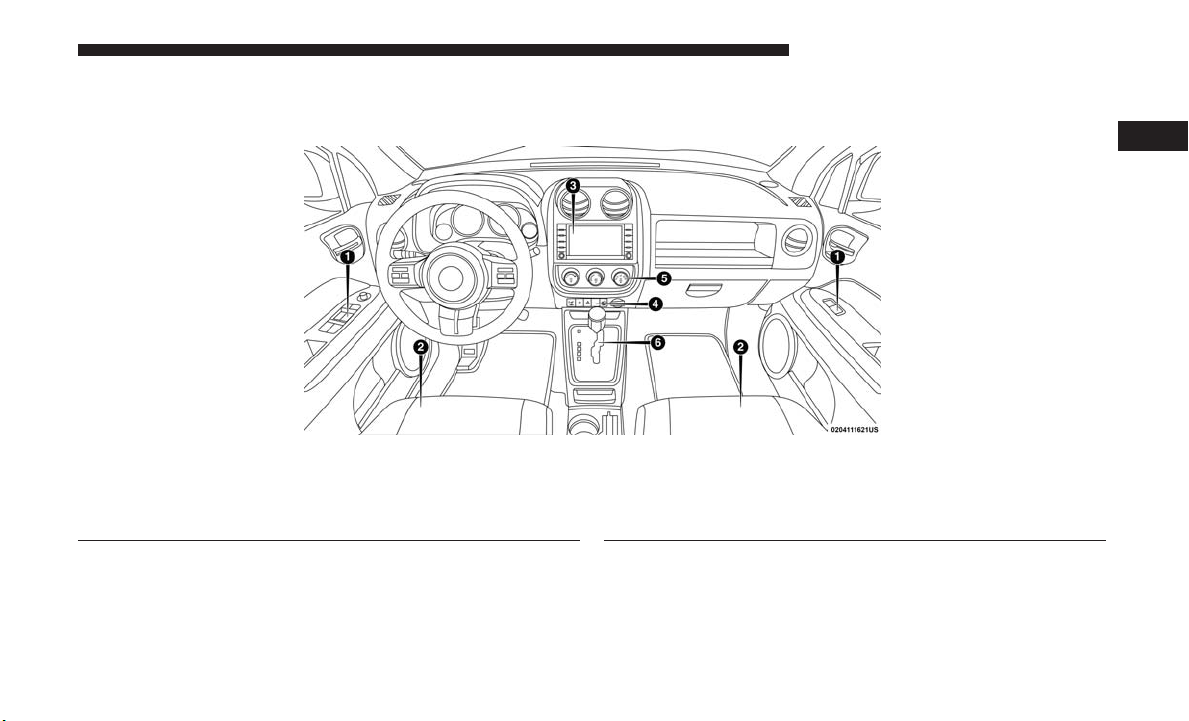
INSTRUMENT PANEL
Instrument Panel
1 — Air Outlets 5 — Storage Bin 9 — Heated Seat Switch – If Equipped
2 — Demisters 6 — Glove Compartment 10 — Hazard Warning Flasher
3 — Instrument Cluster 7 — Climate Controls 11 — ESC OFF Switch – If Equipped
4 — Radio 8 — Power Outlet 12 — Heated Seat Switch – If Equipped
INTERIOR
1 — Power Window Switches
2 — Seats
3 — Radio
GRAPHICAL TABLE OF CONTENTS 13
2
Interior Features
4 — Switch Panel
5 — Climate Controls
6 — Transmission Gear Selector


GETTING TO KNOW YOUR VEHICLE
CONTENTS
䡵 KEYS .................................19
▫ A Word About Your Keys .................19
▫ Locking Doors With A Key ................19
▫ To Unlock The Doors And Liftgate ...........19
▫ Key Fob Unlock, Driver Door/All First Press ....20
▫ Programming Additional Key Fobs ...........20
▫ Key Fob Battery Replacement ..............20
▫ General Information .....................21
䡵 IGNITION SWITCH .......................21
▫ Ignition Key Removal ....................21
▫ Key Fob-In-Ignition Reminder ..............23
䡵 SENTRY KEY ...........................23
▫ Replacement Key Fobs ...................24
▫ Customer Key Programming ...............24
▫ General Information .....................25
3
䡵 VEHICLE SECURITY ALARM — IF EQUIPPED . . .25
▫ To Arm The System .....................26
▫ Rearming The System ....................26
▫ To Disarm The System ....................26
▫ Vehicle Security Alarm Manual Override .......26
䡵 REMOTE STARTING SYSTEM — IF EQUIPPED . . .26
▫ How To Use Remote Start..................27
▫ Remote Start Abort Message Display ..........27
▫ To Enter Remote Start ....................28
▫ To Exit Remote Start Mode Without Driving The
Vehicle ...............................28
▫ To Exit Remote Start Mode And Drive The
Vehicle ...............................28
䡵 DOOR LOCKS ..........................29

16 GETTING TO KNOW YOUR VEHICLE
▫ Manual Door Locks ......................29
▫ Automatic Dimming Mirror — If Equipped .....44
▫ Power Door Locks ......................30
▫ Child-Protection Door Lock System — Rear
Doors ...............................32
䡵 SEATS ................................34
▫ Manual Seats...........................34
▫ Power Seats — If Equipped ................36
▫ Heated Seats — If Equipped ...............38
▫ Folding Rear Seat .......................39
▫ Reclining Rear Seat — If Equipped ...........40
䡵 HEAD RESTRAINTS ......................40
▫ Supplemental Active Head Restraints — Front
Seats ................................41
▫ Rear Head Restraints .....................43
䡵 STEERING WHEEL .......................43
▫ Tilt Steering Column .....................43
䡵 MIRRORS ..............................44
▫ Inside Day/Night Mirror ..................44
▫ Outside Mirror — Driver Side ..............45
▫ Outside Mirror — Passenger Side ............45
▫ Folding Outside Mirrors ..................45
▫ Power Mirrors .........................46
▫ Heated Mirrors — If Equipped .............46
▫ Vanity Mirrors — If Equipped ..............46
▫ Sun Visor “Slide-On-Rod” Feature — If
Equipped .............................47
䡵 EXTERIOR LIGHTS .......................47
▫ Headlights And Parking Lights .............47
▫ Daytime Running Lights — If Equipped .......47
▫ High/Low Beam Switch ..................47
▫ Flash-To-Pass ..........................47
▫ Automatic Headlights — If Equipped .........48
▫ Fog Lights — If Equipped .................48
▫ Turn Signals ...........................49

▫ Lights-On Reminder .....................49
▫ Headlights On With Wipers (Available With
Automatic Headlights Only) ...............49
GETTING TO KNOW YOUR VEHICLE 17
▫ Automatic Temperature Control (ATC) — If
Equipped .............................64
▫ Operating Tips .........................65
䡵 INTERIOR LIGHTS .......................50
▫ Instrument Panel Dimming.................50
▫ Map/Reading Lights .....................50
䡵 WINDSHIELD WIPERS AND WASHERS ........51
▫ Windshield Wiper Operation................52
▫ Intermittent Wiper System .................52
▫ Windshield Washers .....................53
▫ Headlights On With Wipers (Available With
Automatic Headlights Only) ...............53
▫ Mist Feature ...........................53
▫ Rear Window Wiper/Washer ...............54
䡵 CLIMATE CONTROLS .....................55
▫ Manual Climate Controls ..................55
▫ Automatic Climate Controls ................59
䡵 POWER WINDOWS — IF EQUIPPED ..........68
▫ Power Window Switches ..................68
▫ Auto-Down............................69
▫ Window Lockout Switch...................69
䡵 POWER SUNROOF — IF EQUIPPED ..........70
▫ Opening .............................70
▫ Closing ..............................71
▫ Wind Buffeting .........................71
▫ Sunshade Operation......................71
▫ Pinch Protect Feature .....................72
▫ Sunroof Maintenance .....................72
▫ Ignition Off Operation ....................72
䡵 TO OPEN AND CLOSE THE HOOD ...........72
䡵 LIFTGATE .............................74
3

18 GETTING TO KNOW YOUR VEHICLE
▫ Cargo Area Features .....................75
䡵 CONSOLE FEATURES .....................86
䡵 GARAGE DOOR OPENER — IF EQUIPPED .....78
▫ Before You Begin Programming HomeLink .....79
▫ Programming A Rolling Code ...............80
▫ Programming A Non-Rolling Code ...........81
▫ Canadian/Gate Operator Programming ........82
▫ Using HomeLink .......................84
▫ Security ..............................84
▫ Troubleshooting Tips .....................84
▫ General Information......................85
䡵 INTERNAL EQUIPMENT ...................87
▫ Glove Compartment And Storage Bin .........87
▫ Door Storage ...........................88
▫ Electrical Power Outlets ..................89
▫ Power Inverter — If Equipped ..............91
▫ Cupholders ............................92
䡵 ROOF LUGGAGE RACK — IF EQUIPPED ......93

KEYS
Your vehicle uses a keyless ignition system. The ignition
system consists of a key fob with Remote Keyless Entry
(RKE) and a START/STOP push button ignition system.
The Remote Keyless Entry system consists of a key fob and
Keyless Enter-N-Go feature.
NOTE: The key fob may not be found if it is located next to
a mobile phone, laptop or other electronic device; these
devices may block the key fob’s wireless signal.
A Word About Your Keys
The authorized dealer that sold you your new vehicle has
the key code numbers for your vehicle locks. These numbers can be used to order duplicate Remote Keyless Entry
(RKE) key fobs. Ask your authorized dealer for these
numbers and keep them in a safe place.
GETTING TO KNOW YOUR VEHICLE 19
3
Key Fob
Locking Doors With A Key
You can insert the key with either side up. To lock the door,
turn the key to the right. To unlock the door, turn the key
to the left. Refer to ”Body Lubrication” in Dealer Service”
in “Servicing And Maintenance” for further information.
To Unlock The Doors And Liftgate
Push and release the unlock button on the key fob once to
unlock the driver’s door or twice within five seconds to
unlock all doors and liftgate. The turn signal lights will
flash to acknowledge the unlock signal. The illuminated
entry system will also turn on.

20 GETTING TO KNOW YOUR VEHICLE
Key Fob Unlock, Driver Door/All First Press
This feature lets you program the system to unlock either
the driver’s door or all doors on the first push of the unlock
button on the key fob. To change the current setting,
proceed as follows:
• For vehicles equipped with the instrument cluster display, refer to “Instrument Cluster Display/Personal Settings (Customer-Programmable Features)” in “Getting
To Know Your Instrument Panel” for further information.
• For vehicles not equipped with the instrument cluster
display, perform the following steps:
1. Push and hold the lock button on a programmed key
fob for at least four seconds but no longer than ten
seconds. Then, push and hold the unlock button
while still holding the lock button.
2. Release both buttons at the same time.
3. Test the feature while outside of the vehicle by
pushing the lock/unlock buttons on the key fob with
the ignition in the lock position and the key fob
removed.
4. Repeat these steps if you want to return this feature
to its previous setting.
NOTE: Pushing the lock button on the key fob while you
are inside the vehicle will activate the vehicle security
alarm. Opening a door with the vehicle security alarm
activated will cause the alarm to sound. Push the unlock
button to deactivate the vehicle security alarm.
Programming Additional Key Fobs
Refer to “Sentry Key” in this section for further information.
If you do not have a programmed key fob, contact your
authorized dealer for details.
Key Fob Battery Replacement
NOTE: Perchlorate Material – special handling may apply.
See www.dtsc.ca.gov/hazardouswaste/perchlorate
The recommended replacement battery is CR2032.
1. If the key fob is equipped with a screw, remove the
screw. With the key fob buttons facing down, use a flat
blade screwdriver to pry the two halves of the key fob
apart. Make sure not to damage the elastomer seal
during removal.

Separating Case Halves
2. Remove and replace the battery. Avoid touching the new
battery with your fingers. Skin oils may cause battery
deterioration. If you touch a battery, clean it with
rubbing alcohol.
3. To reassemble the key fob case, snap the two halves
together.
NOTE: If the key fob is equipped with a screw, reinstall
and tighten the screw until snug.
GETTING TO KNOW YOUR VEHICLE 21
General Information
The following regulatory statement applies to all Radio
Frequency (RF) devices equipped in this vehicle:
This device complies with Part 15 of the FCC Rules and
with Industry Canada license-exempt RSS standard(s).
Operation is subject to the following two conditions:
1. This device may not cause harmful interference, and
2. This device must accept any interference received, including interference that may cause undesired operation.
NOTE: Changes or modifications not expressly approved
by the party responsible for compliance could void the
user’s authority to operate the equipment.
IGNITION SWITCH
Ignition Key Removal
1. Place the gear selector in PARK (if equipped with an
automatic transmission).
2. Place the ignition in the ACC (Accessory) position.
3
3. Push the key and cylinder inward and rotate the key to
the LOCK position.

22 GETTING TO KNOW YOUR VEHICLE
4. Remove the key from the ignition. NOTE: If you try to remove the key before you place the
gear selector in PARK, the key may become trapped
temporarily in the ignition. If this occurs, place the gear
selector in PARK, rotate the key clockwise slightly, and
then remove the key as described above. If a malfunction
occurs, the system will trap the key in the ignition to warn
you that this safety feature is inoperable. The engine can be
started and stopped but the key cannot be removed until
you obtain service.
WARNING!
• Before exiting a vehicle, always shift the automatic
Ignition Positions
1 — LOCK
2 — ACC (ACCESSORY)
3 — ON/RUN
4 — START
transmission into PARK or the manual transmission
into FIRST gear or REVERSE, apply the parking
brake, turn the engine OFF, remove the key fob from
the ignition and lock your vehicle.
• Never leave children alone in a vehicle, or with
access to an unlocked vehicle.
• Allowing children to be in a vehicle unattended is
dangerous for a number of reasons. A child or others
could be seriously or fatally injured. Children
should be warned not to touch the parking brake,
brake pedal or the gear selector.
(Continued)
WARNING! (Continued)
• Do not leave the key fob in or near the vehicle, or in
a location accessible to children. A child could operate power windows, other controls, or move the
vehicle.
• Do not leave children or animals inside parked
vehicles in hot weather. Interior heat build-up may
cause serious injury or death.
CAUTION!
Always remove the key fobs from the vehicle and lock
all doors when leaving the vehicle unattended.
Key Fob-In-Ignition Reminder
Opening the driver’s door when the key is in the ignition
and the ignition position is LOCK or ACC sounds a signal
to remind you to remove the key.
NOTE: With the driver’s door open and the key in the
ignition, the power door locks will not lock, and key fob
will not function.
GETTING TO KNOW YOUR VEHICLE 23
SENTRY KEY
The Sentry Key Immobilizer System prevents unauthorized vehicle operation by disabling the engine. The system
does not need to be armed or activated. Operation is
automatic, regardless of whether the vehicle is locked or
unlocked.
The system uses key fobs that have an embedded electronic
chip (transponder) to prevent unauthorized vehicle operation. Therefore, only key fobs that are programmed to the
vehicle can be used to start and operate the vehicle. The
system will shut the engine off in two seconds if someone
uses an invalid key to try to start the engine.
NOTE: A key fob that has not been programmed is also
considered an invalid key, even if it is cut to fit the ignition
or lock cylinder for that vehicle.
During normal operation, after placing the ignition in the
on position, the vehicle security light will turn on for three
seconds for a bulb check. If the light remains on after the
bulb check, it indicates that there is a problem with the
electronics. In addition, if the vehicle security light begins
to flash after the bulb check, it indicates that someone used
an invalid key to try to start the engine. Either of these
conditions will result in the engine being shut off after two
seconds.
3

24 GETTING TO KNOW YOUR VEHICLE
If the vehicle security light turns on during normal vehicle
operation (vehicle running for longer than ten seconds), it
indicates that there is a fault in the electronics. Should this
occur, have the vehicle serviced as soon as possible by an
authorized dealer.
Duplication of key fobs may be performed at an authorized
dealer or by following the customer key programming
procedure. This procedure consists of programming a
blank key fob to the vehicle electronics. A blank key fob is
one that has never been programmed.
CAUTION!
The Sentry Key Immobilizer system is not compatible
with some aftermarket remote starting systems. Use of
these systems may result in vehicle starting problems
and loss of security protection.
All of the key fobs provided with your new vehicle have
been programmed to the vehicle electronics.
Replacement Key Fobs
NOTE: Only key fobs that are programmed to the vehicle
electronics can be used to start and operate the vehicle.
Once a key fob is programmed to a vehicle, it cannot be
programmed to any other vehicle.
CAUTION!
Always remove the Sentry Keys from the vehicle and
lock all doors when leaving the vehicle unattended.
NOTE: When having the Sentry Key Immobilizer System
serviced, bring all vehicle key fobs with you to an authorized dealer.
Customer Key Programming
If you have two valid key fobs, you can program new key
fobs to the Sentry Key Immobilizer system by performing
the following procedure:
1. Cut the additional key(s) to match the ignition and lock
cylinder key code.
2. Insert the first valid key into the ignition. Place the
ignition in the ON/RUN position for at least three
seconds, but no longer than 15 seconds. Then, place the
ignition in the LOCK position and remove the first key.
3. Insert the second valid key into the ignition. Place the
ignition in the ON/RUN position within 15 seconds.
After 10 seconds, a chime will sound. In addition, the

Vehicle Security Light will begin to flash. Place the
ignition in the LOCK position and remove the second
key.
4. Insert a blank key into the ignition. Place the ignition in
the ON/RUN position within 60 seconds. After 10
seconds, a single chime will sound. In addition, the
Vehicle Security Light will stop flashing. To indicate that
programming is complete, the Vehicle Security Light
will turn on again for three seconds and then turn off.
The new key is programmed. The key fob will also be
programmed during this procedure.
Repeat this procedure to program up to eight keys. If you
do not have a programmed key fob, contact your authorized dealer for details.
NOTE: If a programmed key fob is lost, see your authorized dealer to have all remaining key fobs erased from the
system’s memory. This will prevent the lost key from
starting your vehicle. The remaining key fobs must then be
reprogrammed. All vehicle key fobs must be taken to an
authorized dealer at the time of service to be reprogrammed.
GETTING TO KNOW YOUR VEHICLE 25
General Information
The following regulatory statement applies to all radio
frequency (RF) devices equipped in this vehicle:
This device complies with Part 15 of the FCC Rules and
with Industry Canada license-exempt RSS standard(s).
Operation is subject to the following two conditions:
1. This device may not cause harmful interference, and
2. This device must accept any interference received, including interference that may cause undesired operation.
NOTE: Changes or modifications not expressly approved
by the party responsible for compliance could void the
user’s authority to operate the equipment.
VEHICLE SECURITY ALARM — IF EQUIPPED
This vehicle security alarm monitors the doors, liftgate,
and ignition switch for unauthorized operation.
When the alarm is activated, the interior switches for door
locks are disabled. The vehicle security alarm provides
both audio and visual signals, the horn will sound, the
headlights, park lamps and/or turn signals will flash
repeatedly for three minutes. If the disturbance is still
3

26 GETTING TO KNOW YOUR VEHICLE
present (driver’s door, passenger door, other doors, ignition) after three minutes, the parking lights and tail lights
will flash for an additional 15 minutes.
To Arm The System
1. Remove the key fob from the ignition and get out of the
vehicle.
2. Lock the door using either the power door lock switch
or the key fob lock button and close all doors.
3. The vehicle security light in the instrument cluster will
flash rapidly for approximately 16 seconds. This shows
that the vehicle security alarm is arming. During this
period, if a door is opened, the ignition is placed in the
ON/RUN position, or the power door locks are unlocked in any manner, the vehicle security alarm will
automatically disarm. After approximately 16 seconds,
the vehicle security light will flash slowly. This shows
that the vehicle security alarm is fully armed.
Rearming The System
If something triggers the alarm, and no action is taken to
disarm it, the vehicle security alarm will turn off the horn
after three minutes, turn off all of the visual signals after 15
minutes, and then the vehicle security alarm will rearm
itself.
To Disarm The System
Push unlock on the key fob, or insert the key into the
ignition and place the ignition in the ON/RUN position.
If something has triggered the vehicle security alarm in
your absence, the horn will sound three times, and exterior
lights blink three times when you unlock the doors. Check
the vehicle for tampering. The vehicle security alarm is
designed to protect your vehicle. However, you can create
conditions where the vehicle security alarm will arm
unexpectedly. If you remain in the vehicle and lock the
doors with the key fob, once the vehicle security alarm is
armed (after 16 seconds), when you pull the door handle to
exit, the alarm will sound. If this occurs, push the unlock
button on the key fob to disarm the vehicle security alarm.
Vehicle Security Alarm Manual Override
The vehicle security alarm will not arm if you lock the
doors using the manual door lock plunger.
REMOTE STARTING SYSTEM — IF EQUIPPED
This system uses the key fob to remote start the
engine conveniently from outside the vehicle, while
still maintaining security. The system has a range of
approximately 328 ft (100 m). Obstructions between
the vehicle and key fob may reduce this range.
NOTE:
• The vehicle must be equipped with an automatic transmission to be equipped with Remote Start.
• Obstructions between the vehicle and the key fob may
reduce this range.
How To Use Remote Start
All of the following conditions must be met before the
engine will remote start:
• Gear selector in PARK
• Doors closed
• Hood closed
• Hazard switch off
• Brake switch inactive (brake pedal not pushed)
• Ignition key removed from ignition
• Battery at an acceptable charge level
• PANIC button not pushed
• System not disabled from previous remote start event
• Vehicle security alarm not active
GETTING TO KNOW YOUR VEHICLE 27
WARNING!
• Do not start or run an engine in a closed garage or
confined area. Exhaust gas contains Carbon Monoxide (CO) which is odorless and colorless. Carbon
Monoxide is poisonous and can cause serious injury
or death when inhaled.
• Keep key fobs away from children. Operation of the
Remote Start System, windows, door locks or other
controls could cause serious injury or death.
Remote Start Abort Message Display
The following messages will display if the vehicle fails to
remote start or exits remote start prematurely:
• Remote Start Aborted — Door Open
• Remote Start Aborted — Hood Open
• Remote Start Aborted — L/Gate Open
• Remote Start Aborted — Fuel Low
• Remote Start Aborted — System Fault
The message stays active until the ignition is placed in the
ON/RUN position.
3

28 GETTING TO KNOW YOUR VEHICLE
To Enter Remote Start
Push and release the Remote Start button on the key fob
twice within five seconds. The vehicle doors will lock, the
parking lights will flash, and the horn will chirp twice (if
programmed). Then, the engine will start and the vehicle
will remain in the Remote Start mode for a 15-minute cycle.
NOTE:
• The park lamps will turn on and remain on during
Remote Start mode.
• For security, power window and power sunroof operation (if equipped) are disabled when the vehicle is in the
Remote Start mode.
• If your power door locks were unlocked, Remote Start
will automatically lock the doors.
• The engine can be started two consecutive times (two
15-minute cycles) with the key fob. However, the ignition must be placed in the ON/RUN position before you
can repeat the start sequence for a third cycle.
Remote Start will also cancel if any of the following occur:
• The engine stalls or RPM exceeds 2500.
• Any engine warning lamps come on.
• Low Fuel Light turns on.
• The hood is opened.
• The hazard switch is pushed.
• The transmission is moved out of PARK.
• The brake pedal is pushed.
To Exit Remote Start Mode Without Driving The Vehicle
Push and release the Remote Start button one time or allow
the engine to run for the entire 15-minute cycle.
NOTE: To avoid unintentional shut downs, the system will
disable the one time push of the Remote Start button for
two seconds after receiving a valid Remote Start request.
To Exit Remote Start Mode And Drive The Vehicle
Before the end of the 15-minute cycle, push and release the
unlock button on the key fob to unlock the doors and
disarm the vehicle security alarm (if equipped). Then,
insert the key into the ignition and place the ignition in the
ON/RUN position.
NOTE: The ignition must be placed in the ON/RUN
position in order to drive the vehicle.

DOOR LOCKS
Manual Door Locks
Use the manual door lock knob to lock the doors from
inside the vehicle. If the lock knob is down when the door
is closed, the door will lock. Make sure the keys are not
inside the vehicle before closing the door.
GETTING TO KNOW YOUR VEHICLE 29
WARNING!
• For personal security and safety in the event of an
collision, lock the vehicle doors as you drive as well
as when you park and leave the vehicle.
• Never leave children alone in a vehicle, or with
access to an unlocked vehicle. Allowing children to
be in a vehicle unattended is dangerous for a number
of reasons. A child or others could be seriously or
fatally injured. Children should be warned not to
touch the parking brake, brake pedal or the gear
selector.
• Do not leave the key fob in or near the vehicle, or in
a location accessible to children. A child could operate power windows, other controls, or move the
vehicle.
CAUTION!
3
Manual Door Lock Knob
Always remove the key fobs from the vehicle and lock
all doors when leaving the vehicle unattended.

30 GETTING TO KNOW YOUR VEHICLE
Power Door Locks
A power door lock switch is located on the driver’s and
front passenger’s door panel. Push these switches to lock or
unlock the doors and liftgate.
NOTE: To prevent from locking the key in the vehicle, the
power door lock switch will not operate when the key is in
the ignition and either front door is open. A chime will
sound as a reminder to remove the key.
Driver Power Door Lock Switch
1 — Unlock Doors And Liftgate
2 — Lock Doors And Liftgate
Auto Lock Doors — If Equipped
The Automatic Door Lock feature default condition is
enabled. When enabled, the door locks will lock automatically when the vehicle’s speed exceeds 15 mph (24 km/h).

Auto Lock Doors Programming
The Automatic Door Lock feature can be enabled or
disabled as follows:
• For vehicles equipped with the instrument cluster display, refer to “Instrument Cluster Display — If
Equipped/Personal Settings (Customer Programmable
Features)” in “Getting To Know Your Instrument Panel”
for further information.
• For vehicles not equipped with the instrument cluster
display, perform the following procedure:
1. Close all doors and place the key in the ignition.
2. Within 15 seconds, place the ignition between LOCK
and ON/RUN and then back to LOCK four times,
ending up in the LOCK position (do not start the
engine).
3. Within 30 seconds, push the power door lock switch
to lock the doors.
4. A single chime will indicate the completion of the
programming.
5. Repeat these steps if you want to return this feature
to its previous setting.
GETTING TO KNOW YOUR VEHICLE 31
NOTE:
• If you do not hear the chime, it means that the system
did not enter the programming mode and you will need
to repeat the procedure.
• Use the Automatic Door Lock feature in accordance with
local laws.
Automatic Unlock Doors On Exit
The doors will unlock automatically if:
• The Automatic Unlock Doors On Exit feature is enabled.
• The transmission was in gear, and the vehicle speed
returned to 0 MPH (0 km/h).
• The transmission is in NEUTRAL or PARK.
• The driver’s door is opened.
• The doors were not previously unlocked.
3

32 GETTING TO KNOW YOUR VEHICLE
Automatic Unlock Doors On Exit Programming
The Automatic Unlock Doors On Exit feature can be
enabled or disabled as follows:
• For vehicles equipped with the instrument cluster display, refer to “Instrument Cluster Display — If
Equipped/Personal Settings (Customer-Programmable
Features)” in “Getting To Know Your Instrument Panel”
for further information.
• For vehicles not equipped with the instrument cluster
display, perform the following procedure:
1. Close all doors and place the key in the ignition.
2. Within 15 seconds, place the ignition between LOCK
and ON/RUN and then back to LOCK five times,
ending up in the ON/RUN position (do not start the
engine).
3. Within 30 seconds, push the power door unlock
switch to unlock the doors.
4. A single chime will indicate the completion of the
programming.
5. Repeat these steps if you want to return this feature
to its previous setting.
NOTE:
• If you do not hear the chime, it means that the system
did not enter the programming mode and you will need
to repeat the procedure.
• Use the Automatic Unlock Doors On Exit feature in
accordance with local laws.
Child-Protection Door Lock System — Rear Doors
To provide a safer environment for small children riding in
the rear seats, the rear doors are equipped with ChildProtection Door Lock system.
To Engage Or Disengage The Child-Protection Door Lock System
1. Open the rear door.
2. Insert the tip of the ignition key into the lock and rotate
to the lock or unlock position.

Child-Protection Door Lock Location Child-Protection Door Lock Function
3. Repeat steps 1 and 2 for the opposite rear door.
GETTING TO KNOW YOUR VEHICLE 33
3
WARNING!
Avoid trapping anyone in a vehicle in a collision.
Remember that the rear doors can only be opened from
the outside when the Child-Protection locks are engaged.

34 GETTING TO KNOW YOUR VEHICLE
NOTE: For emergency exit with the system engaged,
move the lock knob up (unlocked position), roll down the
window, and open the door with the outside door handle.
SEATS
Seats are a part of the Occupant Restraint System of the
vehicle.
WARNING!
• It is dangerous to ride in a cargo area, inside or
outside of a vehicle. In a collision, people riding in
these areas are more likely to be seriously injured or
killed.
• Do not allow people to ride in any area of your
vehicle that is not equipped with seats and seat belts.
In a collision, people riding in these areas are more
likely to be seriously injured or killed.
• Be sure everyone in your vehicle is in a seat and
using a seat belt properly.
Manual Seats
Manual Front Seat Adjustment
On models equipped with manual seats, the adjusting bar
is located at the front of the seats, near the floor. While
sitting in the seat, lift up on the bar and move the seat
forward or rearward. Release the bar once you have
reached the desired position. Then, using body pressure,
move forward and rearward on the seat to be sure that the
seat adjusters have latched.
Manual Seat Adjusting Bar

WARNING!
• Adjusting a seat while driving may be dangerous.
Moving a seat while driving could result in loss of
control which could cause a collision and serious
injury or death.
• Seats should be adjusted before fastening the seat
belts and while the vehicle is parked. Serious injury
or death could result from a poorly adjusted seat belt.
Manual Seat Height Adjustment — If Equipped
The driver’s seat height can be raised or lowered by using
a lever, located on the outboard side of the seat. Pull
upward on the lever to raise the seat height or push
downward on the lever to lower the seat height.
GETTING TO KNOW YOUR VEHICLE 35
3
Seat Height Adjustment Lever

36 GETTING TO KNOW YOUR VEHICLE
Manual Lumbar — If Equipped
The lumbar adjustment handle is located on the inboard or
outboard side of the seatback. Rotate the lever downward
to increase the lumbar support or rotate the lever upward
to decrease the lumbar support.
Outboard Lumbar Adjustment Lever
Driver’s Seatback Recline
To adjust the seatback, lift the lever located on the outboard
side of the seat, lean back to the desired angle and release
the lever. To return the seatback, lift the lever, lean forward
and release the lever.
Recline Lever
WARNING!
Do not ride with the seatback reclined so that the
shoulder belt is no longer resting against your chest. In
a collision you could slide under the seat belt, which
could result in serious injury or death.
Power Seats — If Equipped
Some models may be equipped with a power driver ’s seat.
The power seat switch is located on the outboard side of
the seat near the floor. Use the switch to move the seat up,
down, forward, rearward, or to tilt the seat.

Power Seat Switch
WARNING!
• Adjusting a seat while driving may be dangerous.
Moving a seat while driving could result in loss of
control which could cause a collision and serious
injury or death.
• Seats should be adjusted before fastening the seat
belts and while the vehicle is parked. Serious injury
or death could result from a poorly adjusted seat belt.
GETTING TO KNOW YOUR VEHICLE 37
CAUTION!
Do not place any article under a power seat or impede
its ability to move as it may cause damage to the seat
controls. Seat travel may become limited if movement
is stopped by an obstruction in the seat’s path.
Adjusting The Seat Forward Or Rearward
The seat can be adjusted both forward and rearward. Push
the seat switch forward or rearward. The seat will move in
the direction of the switch. Release the switch when the
desired position has been reached.
Adjusting The Seat Up Or Down
The height of the seats can be adjusted up or down. Pull
upward or push downward on the seat switch. The seat
will move in the direction of the switch. Release the switch
when the desired position is reached.
Tilting The Seat Up Or Down
The angle of the seat cushion can be adjusted in four
directions. Pull upward or push downward on the front or
rear of the seat switch, the front or rear of the seat cushion
will move in the direction of the switch. Release the switch
when the desired position is reached.
3

38 GETTING TO KNOW YOUR VEHICLE
Heated Seats — If Equipped
On some models, the front driver and passenger seats may
be equipped with heaters in both the seat cushions and
seatbacks. The controls for the front heated seats are
located on the center instrument panel area.
You can choose from HI, LO or OFF heat settings. Amber
indicator lights in each switch indicate the level of heat in
use. Two indicator lights will illuminate for HI, one for LO
and none for OFF.
Push the switch once to select HI-level heating.
Push the switch a second time to select LO-level
heating. Push the switch a third time to shut the
heating elements OFF.
When the HI-level setting is selected, the heater will
provide a boosted heat level during the initial stages of
operation. Then, the heat output will drop to the normal
HI-level. If the HI-level setting is selected, the system will
automatically switch to LO-level after approximately 30
minutes of continuous operation. At that time, the display
will change from HI to LO, indicating the change. When
the LO-level heating is selected, the system automatically
turns the heater and the indicator light OFF after approximately 30 minutes of continuous operation.
NOTE: Once a heat setting is selected, heat will be felt
within two to five minutes.
WARNING!
• Persons who are unable to feel pain to the skin
because of advanced age, chronic illness, diabetes,
spinal cord injury, medication, alcohol use, exhaustion or other physical condition must exercise care
when using the seat heater. It may cause burns even
at low temperatures, especially if used for long
periods of time.
• Do not place anything on the seat or seatback that
insulates against heat, such as a blanket or cushion.
This may cause the seat heater to overheat. Sitting in
a seat that has been overheated could cause serious
burns due to the increased surface temperature of the
seat.

Folding Rear Seat
To provide additional storage area, each rear seatback can
be folded forward. Pull the strap forward to fold the rear
seatback flat.
Rear Seat Release Straps
GETTING TO KNOW YOUR VEHICLE 39
3
Folded Rear Seat
NOTE: You may experience deformation in the seat cush-
ion from the seat belt buckles if the seats are left folded for
an extended period of time. This is normal and by simply
opening the seats to the open position, over time the seat
cushion will return to its normal shape.
To raise the seatback, pull the strap forward and lift the
seatback into its upright position.

40 GETTING TO KNOW YOUR VEHICLE
WARNING!
Be certain that the seatback is securely locked into
position. If the seatback is not securely locked into
position the seat will not provide the proper stability
for child seats and/or passengers. An improperly
latched seat could cause serious injury.
Reclining Rear Seat — If Equipped
For additional comfort, pull the strap forward just enough
to release the seatback latch. Then, push the seatback to a
reclined position, approximately 35 degrees maximum,
and release the strap.
WARNING!
Do not ride with the seatback reclined so that the
shoulder belt is no longer resting against your chest. In
a collision, you could slide under the seat belt and be
seriously or even fatally injured. Use the recliner only
when the vehicle is parked.
HEAD RESTRAINTS
Head restraints are designed to reduce the risk of injury by
restricting head movement in the event of a rear impact.
Head restraints should be adjusted so that the top of the
head restraint is located above the top of your ear.
WARNING!
• All occupants, including the driver, should not operate a vehicle or sit in a vehicle’s seat until the head
restraints are placed in their proper positions in
order to minimize the risk of neck injury in the event
of a crash.
• Head restraints should never be adjusted while the
vehicle is in motion. Driving a vehicle with the head
restraints improperly adjusted or removed could
cause serious injury or death in the event of a
collision.

Supplemental Active Head Restraints — Front Seats
Active Head Restraints (AHRs) are passive, deployable
components, and vehicles with this equipment cannot be
readily identified by any markings, only through visual
inspection of the head restraint. The head restraint will be
split in two halves, with the front half being soft foam and
trim, the back half being decorative plastic.
When AHRs deploy during a rear impact, the front half of
the head restraint extends forward to minimize the gap
between the back of the occupant’s head and the AHR. This
system is designed to help prevent or reduce the extent of
injuries to the driver and front passenger in certain types of
rear impacts. Refer to “Occupant Restraints” in “Safety” for
further information.
GETTING TO KNOW YOUR VEHICLE 41
To raise the head restraint, pull upward on the head
restraint. To lower the head restraint, push the adjustment
button located at the base of the head restraint and push
downward on the head restraint.
3
Adjustment Button

42 GETTING TO KNOW YOUR VEHICLE
For comfort, the Active Head Restraints can be tilted
forward and backward. To tilt the head restraint closer to
the back of your head, pull forward on the bottom of the
head restraint. Push rearward on the bottom of the head
restraint to move the head restraint away from your head.
Active Head Restraint (Normal Position)
Active Head Restraint (Tilted Position)
NOTE:
• The head restraints should only be removed by qualified
technicians, for service purposes only. If either of the
head restraints require removal, see your authorized
dealer.
• In the event of deployment of an Active Head Restraint,
refer to “Occupant Restraints” in “Safety” for further
information.

WARNING!
• All occupants, including the driver, should not operate a vehicle or sit in a vehicle’s seat until the head
restraints are placed in their proper positions in
order to minimize the risk of neck injury in the event
of a collision.
• Do not place items over the top of the Active Head
Restraint, such as coats, seat covers or portable DVD
players. These items may interfere with the operation of the Active Head Restraint in the event of a
collision and could result in serious injury or death.
• Active Head Restraints may be deployed if they are
struck by an object such as a hand, foot or loose
cargo. To avoid accidental deployment of the Active
Head Restraint ensure that all cargo is secured, as
loose cargo could contact the Active Head Restraint
during sudden stops. Failure to follow this warning
could cause personal injury if the Active Head Restraint is deployed.
Rear Head Restraints
The head restraints in the rear are non adjustable. Refer to
“Occupant Restraints” in “Safety” for information on
Tether routing.
GETTING TO KNOW YOUR VEHICLE 43
STEERING WHEEL
Tilt Steering Column
This feature allows you to tilt the steering column upward
or downward. The tilt steering column lever is located on
the left side of the steering column, below the turn signal
lever.
Push down on the lever to unlock the steering column.
With one hand firmly on the steering wheel, move the
steering column up or down, as desired. Push the lever up
to lock the steering column firmly in place.
Tilt Steering Column Lever
3

44 GETTING TO KNOW YOUR VEHICLE
WARNING!
Do not adjust the steering column while driving.
Adjusting the steering column while driving or driving with the steering column unlocked, could cause the
driver to lose control of the vehicle. Failure to follow
this warning may result in serious injury or death.
MIRRORS
Inside Day/Night Mirror
A two-point pivot system allows for horizontal and vertical
mirror adjustment. Adjust the mirror to center on the view
through the rear window.
Headlight glare can be reduced by moving the small
control under the mirror to the night position (toward the
rear of vehicle). The mirror should be adjusted while set in
the day position (toward the windshield).
Inside Day/Night Mirror
Automatic Dimming Mirror — If Equipped
This mirror automatically adjusts for headlight glare from
vehicles behind you. You can turn the feature on or off by
pushing the button at the base of the mirror. The on/off
symbol on the button will illuminate when the autodimming feature is enabled.
NOTE: This feature is disabled when the vehicle is moving
in REVERSE.

Automatic Dimming Mirror
CAUTION!
To avoid damage to the mirror during cleaning, never
spray any cleaning solution directly onto the mirror.
Apply the solution onto a clean cloth and wipe the
mirror clean.
Outside Mirror — Driver Side
Adjust the flat outside mirror so you can just see the side of
your vehicle in the part of the mirror closest to the vehicle
with your head close to the door glass.
GETTING TO KNOW YOUR VEHICLE 45
Outside Mirror — Passenger Side
Adjust the convex outside mirror so you can just see the
side of your vehicle in the part of the mirror closest to the
vehicle with your head close to the center of the vehicle.
WARNING!
Vehicles and other objects seen in the passenger side
convex mirror will look smaller and farther away than
they really are. Relying too much on your passenger
side convex mirror could cause you to collide with
another vehicle or other object. Use your inside mirror
when judging the size or distance of a vehicle seen in
the passenger side convex mirror. Some vehicles will
not have a convex passenger side mirror.
Folding Outside Mirrors
The outside mirrors are hinged and may be moved, manually, either forward or rearward to resist damage. The
hinges have three detent positions; full forward, full rearward and normal.
3

46 GETTING TO KNOW YOUR VEHICLE
Power Mirrors
The power mirror control is located on the driver’s door
trim panel.
Power Mirror Control
To adjust a mirror, turn the control wand toward the left or
right mirror positions indicated. Tilt the control wand in
the direction you want the mirror to move.
When you are finished adjusting the mirror, turn the
control to the center position to prevent accidentally moving a mirror.
Heated Mirrors — If Equipped
These mirrors are heated to melt frost or ice. This
feature is activated whenever you turn on the rear
window defroster. Refer to “Climate Controls” in “Getting
To Know Your Vehicle” for further information.
Vanity Mirrors — If Equipped
To use the vanity mirror, rotate the sun visor down and
swing the mirror cover upward.
Vanity Mirror

Sun Visor “Slide-On-Rod” Feature — If Equipped
The sun visors may be extended out to provide more
coverage of the side glass.
EXTERIOR LIGHTS
Headlights And Parking Lights
Turn the end of the multifunction lever to the first detent to
turn on the parking lights. Turn the end of the lever to the
second detent to turn on the headlights.
Headlight Control
GETTING TO KNOW YOUR VEHICLE 47
Daytime Running Lights — If Equipped
The high beam lights will come on as Daytime Running
Lights (lower intensity) whenever the ignition is ON, the
engine is running, the headlight switch is off, the parking
brake is off, the turn signal is off and the gear selector is in
any position except PARK.
High/Low Beam Switch
Push the multifunction lever away from you to switch the
headlights to high beam. Pull the multifunction lever
toward you to switch the headlights back to low beam.
Flash-To-Pass
You can signal another vehicle with your headlights by
lightly pulling the multifunction lever toward you. This
will turn on the high beam headlights until the lever is
released.
NOTE: If the multifunction lever is held in the flash-topass position for more than 20 seconds, the high beams will
shut off. If this occurs, wait 30 seconds for the next
flash-to-pass operation.
3

48 GETTING TO KNOW YOUR VEHICLE
Automatic Headlights — If Equipped
Turning the end of the multifunction lever to the third
detent (AUTO), will activate the automatic headlight system.
Headlight Switch
With the engine running and the multifunction lever in the
AUTO position, the headlights will turn on and turn off
based on the surrounding light levels.
Fog Lights — If Equipped
The front fog light switch is on the multifunction
lever. To activate the front fog lights, turn on the
parking lights or the low beam headlights and
pull out the end of the multifunction lever.
Front Fog Light Operation
NOTE: The fog lights will only operate with the headlights
on low beam. Selecting high beam headlights will turn off
the fog lights.

Turn Signals
Move the multifunction lever up or down and the arrows
on each side of the instrument cluster flash to show proper
operation of the front and rear turn signal lights.
Turn Signal Operation
NOTE: If either light remains on and does not flash, or
there is a very fast flash rate, check for a defective outside
light bulb. If an indicator fails to light when the lever is
moved, it would suggest that the indicator bulb is defective.
GETTING TO KNOW YOUR VEHICLE 49
Lane Change Assist
Tap the lever up or down once, without moving beyond
the detent, and the turn signal (right or left) will flash three
times. Then, the turn signal (right or left) will automatically
turn off.
Lights-On Reminder
If the headlights or parking lights are left on after the
ignition is turned OFF, a chime will sound to alert the
driver when the driver’s door is opened.
Headlights On With Wipers (Available With Automatic Headlights Only)
When this feature is active, the headlights will turn on
approximately 10 seconds after the wipers are turned on if
the headlight switch is placed in the AUTO position. In
addition, the headlights will turn off when the wipers are
turned off if they were turned on by this feature.
NOTE: The Headlights On with Wipers feature can be
turned on or off using the instrument cluster display. Refer
to “Instrument Cluster Display” in “Getting To Know Your
Instrument Panel” for further information.
3

50 GETTING TO KNOW YOUR VEHICLE
INTERIOR LIGHTS
Instrument Panel Dimming
Rotate the center portion of the lever to the extreme bottom
position to fully dim the instrument panel lights and
prevent the interior lights from illuminating when a door is
opened.
Rotate the center portion of the lever up to increase the
brightness of the instrument panel lights when the parking
lights or headlights are on.
Rotate the center portion of the lever upward to the next
detent position to brighten the odometer and radio when
the parking lights or headlights are on.
Rotate the center portion of the lever upward to the last
detent to turn on the interior lighting.
Dimmer Control
Map/Reading Lights
These lights are mounted between the sun visors above the
rear view mirror. Each light is turned on by pushing the
button. Push the button a second time to turn the light off.
The lights also come on when a door is opened or the
dimmer control is turned fully upward, past the second
detent.

Map/Reading Lights
NOTE:
The lights will remain on until the switch is pushed a
second time, so be sure they have been turned off before
leaving the vehicle. They will not turn off automatically.
GETTING TO KNOW YOUR VEHICLE 51
WINDSHIELD WIPERS AND WASHERS
The windshield wiper/washer control lever is located on the right side of the steering column. The
front wipers are operated by rotating a switch,
located on the end of the lever. For information on the rear
wiper/washer, refer to “Rear Window Wiper/Washer” in
this section.
Wiper/Washer Control Lever
3

52 GETTING TO KNOW YOUR VEHICLE
CAUTION!
• Turn the windshield wipers off when driving
through an automatic car wash. Damage to the windshield wipers may result if the wiper control is left in
any position other than off.
• In cold weather, always turn off the wiper switch and
allow the wipers to return to the park position before
turning off the engine. If the wiper switch is left on
and the wipers freeze to the windshield, damage to
the wiper motor may occur when the vehicle is
restarted.
• Always remove any buildup of snow that prevents
the windshield wiper blades from returning to the
off position. If the windshield wiper control is
turned off and the blades cannot return to the off
position, damage to the wiper motor may occur.
Windshield Wiper Operation
Rotate the end of the lever upward to the second detent
past the intermittent settings for low-speed wiper operation. Rotate the end of the lever upward to the third detent
past the intermittent settings for high-speed wiper operation.
Windshield Wiper Operation
Intermittent Wiper System
Use the intermittent wiper when weather conditions make
a single wiping cycle, with a variable pause between cycles,
desirable. Select the delay interval by turning the end of the
lever. Rotate the end of the lever upward (clockwise) to
decrease the delay time and downward (counterclockwise)
to increase the delay time. The delay can be regulated from
a maximum of approximately 18 seconds between cycles,
to a cycle every second.

NOTE: The wiper delay times depend on vehicle speed. If
the vehicle is moving less than 10 mph (16 km/h), delay
times will be doubled.
Windshield Washers
To use the washer, pull the control lever toward you and
hold while spray is desired. If the lever is pulled while in
the delay range, the wiper will operate in low-speed while
the lever is pulled and for two wipe cycles after the lever is
released, and then resume the intermittent interval previously selected.
If the lever is pulled while in the off position, the wipers
will operate for two wipe cycles, then turn off.
WARNING!
Sudden loss of visibility through the windshield could
lead to a collision. You might not see other vehicles or
other obstacles. To avoid sudden icing of the windshield during freezing weather, warm the windshield
with the defroster before and during windshield
washer use.
GETTING TO KNOW YOUR VEHICLE 53
Headlights On With Wipers (Available With Automatic Headlights Only)
When this feature is active, the headlights will turn on
approximately 10 seconds after the wipers are turned on if
the headlight switch is placed in the AUTO position. In
addition, the headlights will turn off when the wipers are
turned off if they were turned on by this feature.
NOTE: The Headlights On with Wipers feature can be
turned on or off using the instrument cluster display. Refer
to “Instrument Cluster Display” in “Getting To Know Your
Instrument Panel” for further information.
Mist Feature
Push down on the control lever to activate a single wipe to
clear the windshield of road mist or spray from a passing
vehicle. As long as the lever is held down, the wipers will
continue to operate.
3

54 GETTING TO KNOW YOUR VEHICLE
NOTE: The mist feature does not activate the washer
pump; therefore, no washer fluid will be sprayed on the
windshield. The wash function must be used in order to
spray the windshield with washer fluid.
Rear Window Wiper/Washer
The rear wiper/washer is controlled by a rotary switch
located on the center portion of the control lever. The
control lever is located on the right side of the steering
column.
Mist Operation
Rear Wiper/Washer Control Lever
Rotate the center portion of the lever upward to the
first detent position for rear wiper operation.

NOTE: The rear wiper operates in an intermittent mode
only.
Rotate the center portion of the lever past the
first detent to activate the rear washer. The
washer pump and the wiper will continue to
operate as long as the switch is held (for a
maximum of 10 seconds). Upon release, the wiper will
continue to cycle two times before returning to the set
position.
If the rear wiper is operating when the ignition is turned
OFF, the wiper will automatically return to the “park”
position if power accessory delay is active. Power accessory delay can be cancelled by opening the door, if this
happens the rear wiper will stop at its current position and
will not go to “park”.
CLIMATE CONTROLS
The Climate Control System allows you to regulate the
temperature, airflow, and direction of air circulating
throughout the vehicle. The controls are located on the
instrument panel below the radio.
GETTING TO KNOW YOUR VEHICLE 55
Manual Climate Controls
The controls for the manual heating and air conditioning
system in this vehicle consist of a series of outer rotary
dials and inner push knobs. These comfort controls can be
set to obtain desired interior conditions.
Manual Climate Controls
3

56 GETTING TO KNOW YOUR VEHICLE
Manual Climate Control Descriptions
Icon Description
Blower Control
There are seven blower speeds. Use this control to regulate the amount of air forced through the
system in any mode you select. The blower speed increases as you move the control clockwise
from the off position.
NOTE: Depending on the configuration, your vehicle may be equipped with four blower
speeds.
A/C Button
Press and release to change the current setting, the indicator illuminates when A/C is on. Performing this function again will cause the A/C operation to switch into manual mode and the
A/C indicator will turn off.
Temperature Control
Use this control to regulate the temperature of the air inside the passenger compartment. Rotating the knob counterclockwise, from top center into the blue area of the scale, indicates cooler
temperatures. Rotating the knob clockwise, into the red area, indicates warmer temperatures.
Modes Control
Turn the knob to adjust airflow distribution. The airflow distribution mode can be adjusted so
air comes from the instrument panel outlets, floor outlets, defrost outlets and demist outlets.

Icon Description
Panel Mode
Panel Mode
Air comes from the outlets in the instrument panel. Each of these outlets can be individually
adjusted to direct the flow of air. The air vanes of the center outlets and outboard outlets can be
moved up and down or side to side to regulate airflow direction. There is a shut off wheel located below the air vanes to shut off or adjust the amount of airflow from these outlets.
Bi-Level Mode
Bi-Level Mode
Air comes from the instrument panel outlets and floor outlets. A slight amount of air is directed
through the defrost and side window demister outlets.
NOTE: BI-LEVEL mode is designed under comfort conditions to provide cooler air out of the
panel outlets and warmer air from the floor outlets.
Floor Mode
Floor Mode
Air comes from the floor outlets. A slight amount of air is directed through the defrost and side
window demister outlets.
GETTING TO KNOW YOUR VEHICLE 57
3
Mix Mode
Mix Mode
Air is directed through the floor, defrost, and side window demister outlets. This setting works
best in cold or snowy conditions that require extra heat to the windshield. This setting is good
for maintaining comfort while reducing moisture on the windshield.

58 GETTING TO KNOW YOUR VEHICLE
Icon Description
Recirculation Button
Push and release this button to change the system between recirculation mode and outside air
mode. Recirculation can be used when outside conditions such as smoke, odors, dust, or high
humidity are present.
NOTE:
•
Continuous use of the Recirculation mode may make the inside air stuffy and window fogging may occur. Extended use of this mode is not recommended.
•
The use of the Recirculation mode in cold or damp weather could cause windows to fog on
the inside, because of moisture buildup inside the vehicle. Select the outside air position for
maximum defogging.
•
Recirculation can be used in all modes except for Defrost.
•
The A/C can be deselected manually without disturbing the mode control selection.
Front Defrost Mode
Turn the knob to the Front Defrost position. Air comes from the windshield and side window
demist outlets. When the defrost button is selected, the blower level will increase. Use Defrost
mode with maximum temperature settings for best windshield and side window defrosting and
defogging.
Rear Defrost Button
Push and release the Rear Defrost Control button to turn on the rear window defroster and the
heated outside mirrors (if equipped). An indicator will illuminate when the rear window defroster is on. The rear window defroster automatically turns off after 10 minutes.

CAUTION!
Failure to follow these cautions can cause damage to
the heating elements:
• Use care when washing the inside of the rear window. Do not use abrasive window cleaners on the
interior surface of the window. Use a soft cloth and a
mild washing solution, wiping parallel to the heating elements. Labels can be peeled off after soaking
with warm water.
• Do not use scrapers, sharp instruments, or abrasive
window cleaners on the interior surface of the window.
• Keep all objects a safe distance from the window.
GETTING TO KNOW YOUR VEHICLE 59
Automatic Climate Controls
3
Automatic Temperature Controls

60 GETTING TO KNOW YOUR VEHICLE
Automatic Climate Control Descriptions
Icon Description
Blower Control
There are seven blower speeds. Use this control to regulate the amount of air forced through the
system in any mode you select. The blower speed increases as you move the control clockwise
from the OFF position.
NOTE: Depending on the configuration, your vehicle may be equipped with four blower
speeds.
AUTO Setting
Automatically controls the interior cabin temperature by adjusting airflow distribution and
amount. Performing this function will cause the system to switch between manual mode and
automatic modes. Refer to “Automatic Operation” for more information.
A/C Button
Press and release to change the current setting, the indicator illuminates when A/C is on. Performing this function again will cause the A/C operation to switch into manual mode and the
A/C indicator will turn off.
Temperature Control
Use this control to regulate the temperature of the air inside the passenger compartment. Rotating the knob counterclockwise, from top center into the lower numbers on the scale, indicates
cooler temperatures. Rotating the knob clockwise, into the higher numbers on the scale, indicates warmer temperatures.

Icon Description
Modes Control
Turn the knob to adjust airflow distribution. The airflow distribution mode can be adjusted so
air comes from the instrument panel outlets, floor outlets, defrost outlets and demist outlets.
Panel Mode
Panel Mode
Air comes from the outlets in the instrument panel. Each of these outlets can be individually
adjusted to direct the flow of air. The air vanes of the center outlets and outboard outlets can be
moved up and down or side to side to regulate airflow direction. There is a shut off wheel located below the air vanes to shut off or adjust the amount of airflow from these outlets.
Bi-Level Mode
Bi-Level Mode
Air comes from the instrument panel outlets and floor outlets. A slight amount of air is directed
through the defrost and side window demister outlets.
NOTE: BI-LEVEL mode is designed under comfort conditions to provide cooler air out of the
panel outlets and warmer air from the floor outlets.
Floor Mode
Floor Mode
Air comes from the floor outlets. A slight amount of air is directed through the defrost and side
window demister outlets.
GETTING TO KNOW YOUR VEHICLE 61
3
Mix Mode
Mix Mode
Air is directed through the floor, defrost, and side window demister outlets. This setting works
best in cold or snowy conditions that require extra heat to the windshield. This setting is good
for maintaining comfort while reducing moisture on the windshield.

62 GETTING TO KNOW YOUR VEHICLE
Icon Description
Recirculation Button
Push and release this button to change the system between recirculation mode and outside air
mode. Recirculation can be used when outside conditions such as smoke, odors, dust, or high
humidity are present.
NOTE:
•
Continuous use of the Recirculation mode may make the inside air stuffy and window fogging may occur. Extended use of this mode is not recommended.
•
The use of the Recirculation mode in cold or damp weather could cause windows to fog on
the inside, because of moisture buildup inside the vehicle. Select the outside air position for
maximum defogging.
•
Recirculation can be used in all modes except for Defrost.
•
The A/C can be deselected manually without disturbing the mode control selection.
Front Defrost Mode
Turn the knob to the Front Defrost position. Air comes from the windshield and side window
demist outlets. When the defrost button is selected, the blower level will increase. Use Defrost
mode with maximum temperature settings for best windshield and side window defrosting and
defogging.
Rear Defrost Button
Push and release the Rear Defrost Control button to turn on the rear window defroster and the
heated outside mirrors (if equipped). An indicator will illuminate when the rear window defroster is on. The rear window defroster automatically turns off after 10 minutes.

CAUTION!
Failure to follow these cautions can cause damage to
the heating elements:
• Use care when washing the inside of the rear window. Do not use abrasive window cleaners on the
interior surface of the window. Use a soft cloth and a
mild washing solution, wiping parallel to the heating elements. Labels can be peeled off after soaking
with warm water.
• Do not use scrapers, sharp instruments, or abrasive
window cleaners on the interior surface of the window.
• Keep all objects a safe distance from the window.
Climate Control Functions
A/C (Air Conditioning)
The Air Conditioning (A/C) button allows the operator to
manually activate or deactivate the air conditioning system. When the air conditioning system is turned on, cool
dehumidified air will flow through the outlets into the
cabin. For improved fuel economy, press the A/C button to
turn off the air conditioning and manually adjust the
blower and airflow mode settings. Also, make sure to select
only Panel, Bi-Level or Floor modes.
GETTING TO KNOW YOUR VEHICLE 63
NOTE:
• If fog or mist appears on the windshield or side glass,
select Defrost mode and increase blower speed if
needed.
• If your air conditioning performance seems lower than
expected, check the front of the A/C condenser (located
in front of the radiator), for an accumulation of dirt or
insects. Clean with a gentle water spray from the front of
the radiator and through the condenser.
Recirculation
When outside air contains smoke, odors, or high humidity,
or if rapid cooling is desired, you may wish to recirculate
interior air by pressing the Recirculation control button.
The recirculation indicator will illuminate when this button
is selected. Press the button a second time to turn off the
Recirculation mode and allow outside air into the vehicle.
3

64 GETTING TO KNOW YOUR VEHICLE
NOTE: In cold weather, use of recirculation mode may lead
to excessive window fogging. The recirculation feature
may be unavailable (button on the touchscreen greyed out)
if conditions exist that could create fogging on the inside of
the windshield. On systems with Manual Climate Controls,
the Recirculation mode is not allowed in Defrost mode to
improve window clearing operation. Recirculation will be
disabled automatically if this mode is selected. Attempting
to use Recirculation while in this mode will cause the LED
in the control button to blink and then turn off.
Automatic Temperature Control (ATC) — If Equipped
Automatic Operation
The Automatic Temperature Control system automatically
maintains the climate in the cabin of the vehicle at the
comfort levels desired by the driver and passenger.
Operation of the system is quite simple.
Turn the Mode Control knob (on the right) and the Blower
Control knob (on the left) to AUTO.
NOTE: The AUTO position performs best for front seat
occupants only.
Manual Operation
This system offers a full complement of manual override
features, which consist of Blower Preferred Automatic,
Mode Preferred Automatic, or Blower and Mode Preferred
Automatic. This means the operator can override the
blower, the mode, or both. There is a manual blower range
for times when the AUTO setting is not desired. The
blower can be set to any fixed blower speed by rotating the
Blower Control knob (on the left).
NOTE: Please read the Automatic Temperature Control
Operation Chart that follows for details.

GETTING TO KNOW YOUR VEHICLE 65
3
The operator can override the AUTO mode setting to
change airflow distribution by rotating the Mode Control
knob (on the right).
Operating Tips
NOTE: Refer to the chart at the end of this section for
suggested control settings for various weather conditions.
Summer Operation
The engine cooling system must be protected with a
high-quality antifreeze coolant to provide proper corrosion
protection and to protect against engine overheating. OAT
coolant (conforming to MS.90032) is recommended. Refer
to “Dealer Service” in “Servicing And Maintenance” for
proper coolant selection.

66 GETTING TO KNOW YOUR VEHICLE
Winter Operation
To ensure the best possible heater and defroster performance, make sure the engine cooling system is functioning
properly and the proper amount, type, and concentration
of coolant is used. Refer to “Dealer Service” in “Servicing
And Maintenance” for proper coolant selection. Use of the
Air Recirculation mode during Winter months is not recommended because it may cause window fogging.
Vacation/Storage
Any time you store your vehicle or keep it out of service
(i.e., vacation) for two weeks or more, run the air conditioning system at idle for about five minutes in fresh air
with the blower setting on high. This will ensure adequate
system lubrication to minimize the possibility of compressor damage when the system is started again.
Window Fogging
Vehicle windows tend to fog on the inside of the glass in
mild, rainy and/or humid weather. Windows may frost on
the inside of the glass in very cold weather. To clear the
windows, select Defrost or Mix mode and increase the
front blower speed. Do not use the Recirculation mode
without A/C for long periods, as fogging may occur.
NOTE: Automatic Temperature Controls (ATC) will automatically adjust the climate control settings to reduce or
eliminate window fogging on the front windshield. When
this occurs, recirculation will be unavailable.
Outside Air Intake
Make sure the air intake, located directly in front of the
windshield, is free of obstructions such as leaves. Leaves
collected in the air intake may reduce airflow, can cause
odor, and if they enter the plenum they could plug the
water drains. In Winter months make sure the air intake is
clear of ice, slush and snow.
A/C Air Filter
The climate control system filters outside air containing
dust, pollen and some odors. Strong odors cannot be totally
filtered out. Refer to “Dealer Service” in “Servicing And
Maintenance” for filter replacement instructions.

Control Setting Suggestions For Various Weather Conditions
Control Settings Suggestions For Various Weather Conditions Chart
GETTING TO KNOW YOUR VEHICLE 67
3

68 GETTING TO KNOW YOUR VEHICLE
POWER WINDOWS — IF EQUIPPED
Power Window Switches
The window controls on the driver ’s door trim panel
control all the door windows. There are single window
controls on each passenger door trim panel, which operate
the passenger door windows. The window controls will
operate when the ignition placed in the ON/RUN or ACC
position.
NOTE:
• For vehicles not equipped with the instrument cluster
display, the power window switches will remain active
for 45 seconds after the ignition is placed in the LOCK
position. Opening either front door will cancel this
feature.
• For vehicles equipped with the instrument cluster display, the power window switches will remain active for
up to 10 minutes after the ignition is placed in the LOCK
position. Opening either front door will cancel this
feature. The time for this feature is programmable. Refer
to “Instrument Cluster Display/Personal Settings
(Customer-Programmable Features)” in “Getting To
Know Your Instrument Panel” for further information.
WARNING!
Never leave children unattended in a vehicle, and do
not let children play with power windows. Do not
leave the key fob in or near the vehicle, or in a location
accessible to children. Occupants, particularly unattended children, can become entrapped by the windows while operating the power window switches.
Such entrapment may result in serious injury or death.
Power Window Switch Location

Auto-Down
The driver’s door window switch has an Auto-Down
feature. Push the window switch past the first detent,
release, and the window will go down automatically. To
cancel the Auto-Down movement, operate the switch in
either the up or down direction and release the switch.
Window Lockout Switch
The window lockout switch on the driver’s door allows
you to disable the window controls on the rear passenger
doors. To disable the window controls on the rear passenger doors, push the window lockout switch. To enable the
rear window controls, push the window lockout switch a
second time.
GETTING TO KNOW YOUR VEHICLE 69
3
Window Lockout Switch

70 GETTING TO KNOW YOUR VEHICLE
POWER SUNROOF — IF EQUIPPED
The power sunroof switch is located on the overhead
console.
WARNING! (Continued)
to children. Occupants, particularly unattended children, can become entrapped by the power sunroof
while operating the power sunroof switch. Such
entrapment may result in serious injury or death.
• In a collision, there is a greater risk of being thrown
from a vehicle with an open sunroof. You could also
be seriously injured or killed. Always fasten your
seat belt properly and make sure all passengers are
properly secured.
• Do not allow small children to operate the sunroof.
Never allow your fingers, other body parts, or any
object to project through the sunroof opening. Injury
may result.
Power Sunroof Switch
WARNING!
• Never leave children alone in a vehicle, or with
access to an unlocked vehicle. Never leave the key
fob in or near the vehicle, or in a location accessible
(Continued)
Opening
Opening Sunroof — Express
Push the switch rearward and release it within one-half
second. The sunroof and sunshade will open automatically
and stop when the full open position is reached. This is
called “Express Open.” During Express Open operation,
any other actuation of the sunroof switch will stop the
sunroof.

Opening Sunroof — Manual Mode
To open the sunroof, push and hold the switch rearward.
The sunroof will move rearward and automatically stop at
full open position. Any release of the switch will stop the
movement. The sunroof and sunshade will remain in a
partially opened condition until the sunroof switch is
pushed again.
Venting Sunroof — Express
Push and release the Vent button within one half second
and the sunroof will open to the vent position. This is
called “Express Vent”, and it will occur regardless of
sunroof position. During Express Vent operation, any other
actuation of the switch will stop the sunroof.
Closing
Closing Sunroof — Express
Push the switch forward and release it within one-half
second and the sunroof will close automatically from any
position. The sunroof will close fully and stop automatically. This is called “Express Close.” During Express Close
operation, any other actuation of the switch will stop the
sunroof.
GETTING TO KNOW YOUR VEHICLE 71
Closing Sunroof — Manual Mode
To close the sunroof, push and hold the switch forward.
The sunroof will move forward and automatically stop at
full closed position. Any release of the switch will stop the
movement and the sunroof will remain in a partially closed
condition until the sunroof switch is pushed again.
Wind Buffeting
Wind buffeting can be described as the perception of
pressure on the ears or a helicopter-type sound in the ears.
Your vehicle may exhibit wind buffeting with the windows
down, or the sunroof (if equipped) in certain open or
partially open positions. This is a normal occurrence and
can be minimized. If the buffeting occurs with the rear
windows open, open the front and rear windows together
to minimize the buffeting. If the buffeting occurs with the
sunroof open, adjust the sunroof opening to minimize the
buffeting or open any window.
Sunshade Operation
The sunshade can be opened manually. However, the
sunshade will open automatically as the sunroof opens.
NOTE: The sunshade cannot be closed if the sunroof is
open.
3

72 GETTING TO KNOW YOUR VEHICLE
Pinch Protect Feature
This feature will detect an obstruction in the opening of the
sunroof during Express Close operation. If an obstruction
in the path of the sunroof is detected, the sunroof will
automatically retract. Remove the obstruction if this occurs. Next, push the switch forward and release to Express
Close.
Sunroof Maintenance
Use only a non-abrasive cleaner and a soft cloth to clean the
glass panel.
Ignition Off Operation
For Vehicles Not Equipped With The Instrument Cluster
Display
The power sunroof switch will remain active for 45 seconds
after the ignition switch is turned to the LOCK position.
Opening either front door will cancel this feature.
For Vehicles Equipped With The Instrument Cluster
Display
The power sunroof switch will remain active for up to
approximately ten minutes after the ignition switch is
turned to the LOCK position. Opening either front door
will cancel this feature.
TO OPEN AND CLOSE THE HOOD
To open the hood, two latches must be released.
1. Pull the hood release lever located on the left kick panel.
Hood Release Lever
2. Move the safety latch, located outside the vehicle under
the front edge of the hood, toward the center and raise
the hood.

Hood Safety Latch Location Prop Rod Location
Lift the hood prop rod, clipped to the right side (left side
facing hood) of the engine compartment to secure the hood
in the open position. Place the hood prop at the location
stamped into the inner hood surface.
GETTING TO KNOW YOUR VEHICLE 73
3
WARNING!
Be sure the hood is fully latched before driving your
vehicle. If the hood is not fully latched, it could open
when the vehicle is in motion and block your vision.
Failure to follow this warning could result in serious
injury or death.

74 GETTING TO KNOW YOUR VEHICLE
CAUTION!
To prevent possible damage:
• Before closing hood, make sure the hood prop rod is
fully seated into its storage retaining clips.
• Do not slam the hood to close it. Use a firm downward push at the center front edge of the hood to
ensure that both latches engage. Never drive your
vehicle unless the hood is fully closed, with both
latches engaged.
LIFTGATE
NOTE: The key that is used to start the vehicle is also used
to lock or unlock the doors and open the liftgate.
To unlock the liftgate, insert the key into the lock and turn
it to the right (manual lock models only). The liftgate can
also be unlocked using the key fob or by activating the
power door lock switches located on the front doors. The
central locking/unlocking feature (if equipped) can also be
activated from the liftgate key cylinder.
Once unlocked, the liftgate can be opened or closed
without using the key fob. To open the liftgate, squeeze the
liftgate release and pull the liftgate open with one fluid
motion.
Liftgate Handle Location
NOTE:
• In the event of a power malfunction, or the key fob is
inoperative, insert the key fob into the liftgate lock
cylinder and turn to the right (manual lock models
only). Using the liftgate handle, pull the liftgate open
with one fluid motion.
• Although the liftgate has no inside release mechanism,
the liftgate trim panel includes an opening with a
snap-in cap that provides access to release the latch in
the event of an electrical system malfunction.

WARNING!
• Driving with the liftgate open can allow poisonous
exhaust gases into your vehicle. You and your passengers could be injured by these fumes. Keep the
liftgate closed when you are operating the vehicle.
• If you are required to drive with the liftgate open,
make sure that all windows are closed, and the
climate control blower switch is set at high speed. Do
not use the recirculation mode.
Gas props support the liftgate in the open position. However, because the gas pressure drops with temperature, it
may be necessary to assist the props when opening the
liftgate in cold weather.
Cargo Area Features
Cargo Light
The light is mounted in the headliner above the cargo area
to illuminate the cargo area.
GETTING TO KNOW YOUR VEHICLE 75
Cargo Cover
The cargo area trim panels include two notches for mounting the available tonneau cover that accommodates the
reclining rear seat.
To install the Cargo Cover, insert either end of the cover
into one of the two notches located in the rear trim panels.
With one of the cover ends installed, push inward on the
opposite end and install it into the same notch location of
the rear trim panel.
Rear Trim Notches
3

76 GETTING TO KNOW YOUR VEHICLE
Using the handle, pull the cover toward you and guide the
rear cover posts into the guides located on both sides of the
rear trim panel.
Removable Load Floor
The cargo area load floor is removable and can be washed
with mild soap and water.
Cargo Cover Guides
WARNING!
In a collision, a cargo cover loose in the vehicle could
cause injury. It could fly around in a sudden stop and
strike someone in the vehicle. Do not store the cargo
cover on the cargo floor or in the passenger compartment. Remove the cover from the vehicle when taken
from its mounting. Do not store in the vehicle.
Removable Load Floor

Cargo Tie-Down Loops
There are four tie-downs (D-rings) installed in the cargo
area for securing cargo.
Cargo Area Tie-Downs
WARNING!
• Cargo tie-down loops are not safe anchors for a child
seat tether strap. In a sudden stop or collision a loop
(Continued)
GETTING TO KNOW YOUR VEHICLE 77
WARNING! (Continued)
could pull loose and allow the child seat to come
loose. A child could be badly injured. Use only the
anchors provided for child seat tethers.
• The weight and position of cargo and passengers can
change the vehicle center of gravity and vehicle
handling. To avoid loss of control resulting in personal injury, follow these guidelines for loading
your vehicle:
• Always place cargo evenly on the cargo floor. Put
heavier objects as low and as far forward as possible.
• Place as much cargo as possible in front of the rear
axle. Too much weight or improperly placed weight
over or behind the rear axle can cause the rear of the
vehicle to sway.
• Do not pile luggage or cargo higher than the top of
the seatback. This could impair visibility or become
a dangerous projectile in a sudden stop or collision.
• To help protect against personal injury, passengers
should not be seated in the rear cargo area. The rear
cargo space is intended for load carrying purposes
only, not for passengers, who should sit in seats and
use seat belts.
3

78 GETTING TO KNOW YOUR VEHICLE
Fold Down Speakers — If Equipped
When the liftgate is open, the speakers can swing down off
the trim panel to face rearward, for tailgating and other
activities.
The HomeLink buttons, located on either the overhead
console, headliner or sunvisor, designate the three different
HomeLink channels. The HomeLink indicator is located
above the center button.
Fold Down Speakers
GARAGE DOOR OPENER — IF EQUIPPED
HomeLink replaces up to three hand-held transmitters that
operate devices such as garage door openers, motorized
gates, lighting or home security systems. The HomeLink
unit is powered by your vehicles 12 Volt battery.
HomeLink Buttons/Overhead Consoles

HomeLink Buttons/Sunvisor/Headliner
NOTE: HomeLink is disabled when the Vehicle Security
Alarm is active.
Before You Begin Programming HomeLink
Be sure that your vehicle is parked outside of the garage
before you begin programming.
GETTING TO KNOW YOUR VEHICLE 79
For more efficient programming and accurate transmission
of the radio-frequency signal, it is recommended that a new
battery be placed in the hand-held transmitter of the device
that is being programmed to the HomeLink system.
To erase the channels, place the ignition in the ON/RUN
position and push and hold the two outside HomeLink
buttons (I and III) for up 20 seconds or until the red
indicator flashes.
NOTE:
• Erasing all channels should only be performed when
programming HomeLink for the first time. Do not erase
channels when programming additional buttons.
• If you have any problems, or require assistance, please
call toll-free 1-800-355-3515 or, on the Internet at
HomeLink.com for information or assistance.
3

80 GETTING TO KNOW YOUR VEHICLE
Programming A Rolling Code
For programming garage door openers that were manufactured after 1995:
These garage door openers can be identified by the
“LEARN” or “TRAIN” button located where the hanging
antenna is attached to the garage door opener. It is NOT the
button that is normally used to open and close the door.
The name and color of the button may vary by manufacturer.
Training The Garage Door Opener
1 — Door Opener
2 — Training Button
1. Place the ignition in the ON/RUN position.
2. Place the hand-held transmitter 1 to 3 inches (3 to 8 cm)
away from the HomeLink button you wish to program
while keeping the HomeLink indicator light in view.
3. Push and hold the HomeLink button you want to
program while you push and hold the hand-held transmitter button.

4. Continue to hold both buttons and observe the indicator
light. The HomeLink indicator will flash slowly and
then rapidly after HomeLink has received the frequency
signal from the hand-held transmitter. Release both
buttons after the indicator light changes from slow to
rapid.
5. At the garage door opener motor (in the garage), locate
the “LEARN” or “TRAINING” button. This can usually
be found where the hanging antenna wire is attached to
the garage door opener/device motor. Firmly push and
release the “LEARN” or “TRAINING” button. On some
garage door openers/devices there may be a light that
blinks when the garage door opener/device is in the
LEARN/TRAIN mode.
NOTE: You have 30 seconds in which to initiate the next
step after the LEARN button has been pushed.
6. Return to the vehicle and push the programmed
HomeLink button twice (holding the button for two
seconds each time). If the garage door opener/device
activates, programming is complete.
NOTE: If the garage door opener/device does not activate,
push the button a third time (for two seconds) to complete
the training.
GETTING TO KNOW YOUR VEHICLE 81
To program the remaining two HomeLink buttons, repeat
each step for each remaining button. DO NOT erase the
channels.
Programming A Non-Rolling Code
For programming Garage Door Openers manufactured
before 1995:
1. Place the ignition in the ON/RUN position.
NOTE: For vehicles equipped with Keyless Enter-N-Go,
place the ignition in the RUN position with the engine ON.
Make sure while programming HomeLink with the engine
ON that your vehicle is outside of your garage, or that the
garage door remains open at all times.
2. Place the hand-held transmitter 1 to 3 inches (3 to 8 cm)
away from the HomeLink button you wish to program
while keeping the HomeLink indicator light in view.
3. Push and hold the Homelink button you want to
program while you push and hold the hand-held transmitter button.
4. Continue to hold both buttons and observe the indicator
light. The Homelink indicator will flash slowly and then
rapidly after HomeLink has received the frequency
3

82 GETTING TO KNOW YOUR VEHICLE
signal from the hand-held transmitter. Release both
buttons after the indicator light changes from slow to
rapid.
2. Push and hold the desired HomeLink button until the
indicator light begins to flash after 20 seconds. Do not
release the button.
5. Push and hold the programmed HomeLink button and
observe the indicator light.
• If the indicator light stays on constantly, programming
is complete and the garage door/device should activate when the HomeLink button is pushed.
• To program the two remaining HomeLink buttons,
repeat each step for each remaining button. DO NOT
erase the channels.
Reprogramming A Single HomeLink Button (Non-Rolling Code)
To reprogram a channel that has been previously trained,
follow these steps:
1. Cycle the ignition to the ON/RUN position.
NOTE: For vehicles equipped with Keyless Enter-N-Go,
place the ignition in the RUN position with the engine ON.
Make sure while programming HomeLink with the engine
ON that your vehicle is outside of your garage, or that the
garage door remains open at all times.
3. Without releasing the button, proceed with “Programming A Non-Rolling Code” step two and follow all
remaining steps.
Canadian/Gate Operator Programming
For programming transmitters in Canada/United States
that require the transmitter signals to “time-out” after
several seconds of transmission:
Canadian radio frequency laws require transmitter signals
to time-out (or quit) after several seconds of transmission,
which may not be long enough for HomeLink to pick up
the signal during programming. Similar to this Canadian
law, some U.S. gate operators are designed to time-out in
the same manner.
It may be helpful to unplug the device during the cycling
process to prevent possible overheating of the garage door
or gate motor.
1. Cycle the ignition to the ON/RUN position.

NOTE: For vehicles equipped with Keyless Enter-N-Go,
place the ignition in the RUN position with the engine ON.
Make sure while programming HomeLink with the engine
ON that your vehicle is outside of your garage, or that the
garage door remains open at all times.
2. Place the hand-held transmitter 1 to 3 inches (3 to 8 cm)
away from the HomeLink button you wish to program
while keeping the HomeLink indicator light in view.
3. Continue to push and hold the HomeLink button while
you push and release (“cycle”) your hand-held transmitter every two seconds until HomeLink has successfully accepted the frequency signal. The indicator light
will flash slowly and then rapidly when fully trained.
4. Watch for the HomeLink indicator to change flash rates.
When it changes, it is programmed. It may take up to 30
seconds or longer in rare cases. The garage door may
open and close while you are programming.
5. Push and hold the programmed HomeLink button and
observe the indicator light.
GETTING TO KNOW YOUR VEHICLE 83
NOTE:
• If the indicator light stays on constantly, programming
is complete and the garage door/device should activate when the HomeLink button is pushed.
• To program the two remaining HomeLink buttons,
repeat each step for each remaining button. DO NOT
erase the channels.
If you unplugged the garage door opener/device for
programming, plug it back in at this time.
Reprogramming A Single HomeLink Button (Canadian/Gate Operator)
To reprogram a channel that has been previously trained,
follow these steps:
1. Cycle the ignition to the ON/RUN position.
NOTE: For vehicles equipped with Keyless Enter-N-Go,
place the ignition in the RUN position with the engine ON.
Make sure while programming HomeLink with the engine
ON that your vehicle is outside of your garage, or that the
garage door remains open at all times.
2. Push and hold the desired HomeLink button until the
indicator light begins to flash after 20 seconds. Do not
release the button.
3

84 GETTING TO KNOW YOUR VEHICLE
3. Without releasing the button, proceed with
“Canadian/Gate Operator Programming” step 2 and
follow all remaining steps.
Using HomeLink
To operate, push and release the programmed HomeLink
button. Activation will now occur for the programmed
device (i.e. garage door opener, gate operator, security
system, entry door lock, home/office lighting, etc.) The
hand-held transmitter of the device may also be used at
any time.
Security
It is advised to erase all channels before you sell or turn in
your vehicle.
To do this, push and hold the two outside buttons for 20
seconds until the red indicator flashes.
NOTE: All channels will be erased. Individual channels
cannot be erased.
The HomeLink Universal Transceiver is disabled when the
Vehicle Security Alarm is active.
Troubleshooting Tips
If you are having trouble programming HomeLink, here
are some of the most common solutions:
• Replace the battery in the Garage Door Opener handheld transmitter.
• Push the LEARN button on the Garage Door Opener to
complete the training for a Rolling Code.
• Did you unplug the device for programming and remember to plug it back in?
If you have any problems, or require assistance, please call
toll-free 1-800-355-3515 or, on the Internet at
HomeLink.com for information or assistance.

WARNING!
• Vehicle exhaust contains carbon monoxide, a dangerous gas. Do not run your vehicle in the garage while
programming the transceiver. Exhaust gas can cause
serious injury or death.
• Your motorized door or gate will open and close
while you are programming the universal transceiver. Do not program the transceiver if people, pets
or other objects are in the path of the door or gate.
Only use this transceiver with a garage door opener
that has a “stop and reverse” feature as required by
Federal safety standards. This includes most garage
door opener models manufactured after 1982. Do not
use a garage door opener without these safety features. Call toll-free 1-800-355-3515 or, on the Internet
at HomeLink.com for safety information or assistance.
GETTING TO KNOW YOUR VEHICLE 85
General Information
This device complies with FCC rules Part 15 and Industry
Canada RSS-210. Operation is subject to the following two
conditions:
1. This device may not cause harmful interference, and
2. This device must accept any interference received, including interference that may cause undesired operation.
NOTE:
• The transmitter has been tested and it complies with
FCC and IC rules. Changes or modifications not expressly approved by the party responsible for compliance could void the user ’s authority to operate the
device.
• The term IC before the certification/registration number
only signifies that Industry Canada technical specifications were met.
3

86 GETTING TO KNOW YOUR VEHICLE
CONSOLE FEATURES
The floor console contains both an upper and lower storage
compartment.
To open the upper storage compartment, push inward on
the upper handle to unlatch the upper lid and lift the lid
open.
To open the lower storage compartment, lift upward on the
lower handle to unlatch the lower storage compartment
and lift the lid open.
Lower Storage Compartment
WARNING!
Upper Storage Compartment
Do not operate this vehicle with a console compartment lid in the open position. Driving with the console
compartment lid open may result in injury in a collision.

INTERNAL EQUIPMENT
Glove Compartment And Storage Bin
Located on the passenger side of the instrument panel are
an upper storage bin and a lower glove compartment.
Storage Bins
1 — Upper Storage Bin
2 — Lower Glove Compartment
GETTING TO KNOW YOUR VEHICLE 87
To open the lower glove compartment, pull outward on the
release handle.
3
Glove Compartment

88 GETTING TO KNOW YOUR VEHICLE
Door Storage
The interior door panels are equipped with lower storage
areas.
Front Door Storage
Rear Door Storage

Electrical Power Outlets
There is a standard 12 Volt (13 Amp) power outlet located
in the Integrated Center Stack (ICS) for added convenience.
This power outlet can power mobile phones, electronics
and other low power devices.
12 Volt Power Outlet
GETTING TO KNOW YOUR VEHICLE 89
Power is available when the ignition switch is in the ON or
ACC position. Insert the cigar lighter or accessory plug into
the outlet for use. To preserve the heating element, do not
hold the lighter in the heating position.
NOTE: To ensure proper operation a MOPAR knob and
element must be used.
CAUTION!
• Do not exceed the maximum power of 160 Watts (13
Amps) at 12 Volts. If the 160 Watt (13 Amp) power
rating is exceeded the fuse protecting the system will
need to be replaced.
• Power outlets are designed for accessory plugs only.
Do not insert any other object in the power outlets as
this will damage the outlet and blow the fuse.
Improper use of the power outlet can cause damage
not covered by your New Vehicle Limited Warranty.
3

90 GETTING TO KNOW YOUR VEHICLE
Power Outlet Fuse Location
WARNING!
To avoid serious injury or death:
• Only devices designed for use in this type of outlet
should be inserted into any 12 Volt outlet.
• Do not touch with wet hands.
• Close the lid when not in use and while driving the
vehicle.
• If this outlet is mishandled, it may cause an electric
shock and failure.
CAUTION!
• Many accessories that can be plugged in draw power
from the vehicle’s battery, even when not in use (i.e.,
cellular phones, etc.). Eventually, if plugged in long
enough, the vehicle’s battery will discharge sufficiently to degrade battery life and/or prevent the
engine from starting.
• Accessories that draw higher power (i.e., coolers,
vacuum cleaners, lights, etc.) will degrade the battery
even more quickly. Only use these intermittently and
with great caution.
• After the use of high power draw accessories, or long
periods of the vehicle not being started (with accessories still plugged in), the vehicle must be driven a
sufficient length of time to allow the generator to
recharge the vehicle’s battery.

Power Inverter — If Equipped
A 115 Volt (150 Watt) AC power inverter is located on the
front of the center console for added convenience. This
outlet can power mobile phones, electronics and other low
power devices requiring power up to 150 Watts. Certain
high-end video games consoles will exceed this power
limit, as will most power tools.
The power inverter is designed with built-in overload
protection. If the power rating of 150 Watts is exceeded, the
power inverter will automatically shut down. Once the
electrical device has been removed from the outlet the
inverter should automatically reset. If the power rating
exceeds approximately 170 Watts, the power inverter may
have to be reset manually. To reset the inverter manually,
unplug the device and plug it in again. To avoid overloading the circuit, check the power ratings on electrical devices
prior to using the inverter.
GETTING TO KNOW YOUR VEHICLE 91
3
115 Volt Power Outlet
WARNING!
To avoid serious injury or death:
• Do not use a three-prong adaptor.
• Do not insert any objects into the receptacles.
• Do not touch with wet hands.
• Close the lid when not in use.
• If this outlet is mishandled, it may cause an electric
shock and failure.

92 GETTING TO KNOW YOUR VEHICLE
CAUTION!
• Many accessories that can be plugged in draw power
from the vehicle’s battery, even when not in use (i.e.,
cellular phones, etc.). Eventually, if plugged in long
enough, the vehicle’s battery will discharge sufficiently to degrade battery life and/or prevent engine
starting.
• Accessories that draw higher power (i.e., coolers,
vacuum cleaners, lights, etc.) will degrade the battery
even more quickly. Only use these intermittently and
with great caution.
• After the use of high power draw accessories, or long
periods of the vehicle not being started (with accessories still plugged in), the vehicle must be driven a
sufficient length of time to allow the generator to
recharge the vehicle’s battery.
Cupholders
Your vehicle is equipped with four cupholders. There are
two illuminated cupholders located in the front.
Front Cupholders

There are two cupholders located in the back for the rear
passengers.
GETTING TO KNOW YOUR VEHICLE 93
NOTE: If not equipped with crossbars, your authorized
dealer can order and install MOPAR crossbars built specifically for this roof rack system.
Rear Cupholders
ROOF LUGGAGE RACK — IF EQUIPPED
The crossbars and siderails are designed to carry the cargo
on vehicles equipped with a luggage rack. The load must
not exceed 150 lbs (68 kg), and should be uniformly
distributed over the luggage rack crossbars.
Distribute cargo weight evenly on the luggage rack crossbars. The luggage rack does not increase the total load
carrying capacity of the vehicle. Be sure the total load of
cargo inside the vehicle plus that on the external rack does
not exceed the maximum vehicle load capacity.
The crossbars must also be secured in one of the seven
detent positions marked with an arrow on the siderails to
prevent movement. To move the crossbars, loosen the
thumb screws located at the upper edge of each crossbar
approximately eight turns, then move the crossbar to the
desired position, keeping the crossbars perpendicular to
the luggage rack side rails. Once the crossbar is in one of
the seven detent positions, retighten the thumb screws to
lock the crossbar into position.
3

94 GETTING TO KNOW YOUR VEHICLE
NOTE:
• To help control wind noise when the crossbars are not in
use, place the front crossbar in the first detent from the
front of the vehicle and the rear crossbar in the second
detent from the rear of the vehicle.
• If the rear crossbar (or any metallic object) is placed over
the satellite radio antenna (if equipped), you may experience interruption of satellite radio reception. For improved satellite radio reception, place the rear crossbar
in the second detent from the rear of the vehicle when
not in use.
WARNING!
Cargo must be securely tied before driving your vehicle. Improperly secured loads can fly off the vehicle,
particularly at high speeds, resulting in personal injury
or property damage. Follow the roof rack cautions
when carrying cargo on your roof rack.
CAUTION!
• To prevent damage to the roof of your vehicle, DO
NOT carry any loads on the luggage rack without
crossbars installed. The load should be secured and
placed on top of the crossbars, not directly on the
roof. If it is necessary to place the load on the roof,
place a blanket or some other protection between the
load and the roof surface.
• To avoid damage to the luggage rack and vehicle, do
not exceed the maximum luggage rack load capacity
of 150 lb (68 kg). Always distribute heavy loads as
evenly as possible and secure the load appropriately.
Long loads which extend over the windshield, such as
•
wood panels or surfboards, or loads with large frontal area
should be secured to both the front and rear of the vehicle.
• Travel at reduced speeds and turn corners carefully
when carrying large or heavy loads on the roof rack.
Wind forces, due to natural causes or nearby truck
traffic, can add sudden upward lift to a load. This is
especially true on large flat loads and may result in
damage to the cargo or your vehicle.

GETTING TO KNOW YOUR INSTRUMENT PANEL
CONTENTS
䡵 INSTRUMENT CLUSTER ...................97
▫ Instrument Cluster Descriptions .............97
䡵 MINI-TRIP COMPUTER — IF EQUIPPED ......109
▫ Control Buttons ........................109
4
䡵 INSTRUMENT CLUSTER DISPLAY — IF
EQUIPPED .............................100
▫ Interactive Display And Controls ............100
▫ Oil Change Indicator System ...............103
▫ Instrument Cluster Display Functions ........103
▫ Compass/Temperature/Audio..............103
▫ Average Fuel Economy ...................104
▫ Distance To Empty (DTE) .................104
▫ Tire Pressure Monitor (TPM) ...............104
▫ Elapsed Time..........................104
▫ Display Units Of Measure In ...............104
▫ Personal Settings (Customer-Programmable
Features) ............................105
▫ STEP Button ..........................109
▫ RESET Button .........................109
▫ Trip Odometer (ODO)....................110
䡵 WARNING/INDICATOR LIGHTS AND
MESSAGES.............................110
▫ Red Telltale Lights ......................111
▫ Yellow Telltale Lights ....................116
▫ Green Telltale Lights.....................124
▫ Blue Telltale Lights......................125
▫ White Telltale Lights.....................126
䡵 ONBOARD DIAGNOSTIC SYSTEM — OBD II . . .127
▫ Onboard Diagnostic System (OBD II)
Cybersecurity .........................127

96 GETTING TO KNOW YOUR INSTRUMENT PANEL
▫ Loose Fuel Filler Cap Message .............128
䡵 EMISSIONS INSPECTION AND MAINTENANCE
PROGRAMS ...........................128

INSTRUMENT CLUSTER
Instrument Cluster
Instrument Cluster Descriptions
1. Speedometer
• The Speedometer shows the vehicle speed in miles per
hour (MPH) and kilometers per hour (km/h).
GETTING TO KNOW YOUR INSTRUMENT PANEL 97
4
Odometer Display / Trip Odometer Display
This display indicates the total distance the vehicle has
been driven.

98 GETTING TO KNOW YOUR INSTRUMENT PANEL
NOTE: U.S. Federal regulations require that upon transfer
of vehicle ownership, the seller certify to the purchaser the
correct mileage that the vehicle has been driven. If your
odometer needs to be repaired or serviced, the repair
technician should leave the odometer reading the same as
it was before the repair or service. If s/he cannot do so,
then the odometer must be set at zero, and a sticker must
be placed in the door jamb stating what the mileage was
before the repair or service. It is a good idea for you to
make a record of the odometer reading before the repair/
service, so that you can be sure that it is properly reset, or
that the door jamb sticker is accurate if the odometer must
be reset at zero.
2. Tachometer
• This gauge measures engine revolutions per minute
(RPM x 1000). Before the pointer reaches the red area,
ease up on the accelerator to prevent engine damage.
3. Temperature Gauge
• The temperature gauge shows engine coolant temperature. Any reading within the normal range indicates that the engine cooling system is operating
satisfactorily.
• The gauge pointer will likely indicate a higher temperature when driving in hot weather or up mountain
grades. It should not be allowed to exceed the upper
limits of the normal operating range.
WARNING!
A hot engine cooling system is dangerous. You or
others could be badly burned by steam or boiling
coolant. You may want to call an authorized dealer for
service if your vehicle overheats. If you decide to look
under the hood yourself, see “Maintaining Your Vehicle”. Follow the warnings under the Cooling System
Pressure Cap paragraph.
CAUTION!
Driving with a hot engine cooling system could damage your vehicle. If the temperature gauge reads “H”
pull over and stop the vehicle. Idle the vehicle with the
air conditioner turned off until the pointer drops back
into the normal range. If the pointer remains on the
“H”, turn the engine off immediately and call an
authorized dealer for service.
4. Instrument Cluster Display — If Equipped / Odometer
Display / Trip Odometer Display
 Loading...