


2019
OWNER’S MANUAL
Cherokee

VEHICLES SOLD IN CANADA
With respect to any Vehicles Sold in Canada, the name
FCA US LLC shall be deemed to be deleted and the name
FCA Canada Inc. used in substitution therefore.
DRIVING AND ALCOHOL
Drunken driving is one of the most frequent causes of
accidents.
Your driving ability can be seriously impaired with blood
alcohol levels far below the legal minimum. If you are
drinking, don’t drive. Ride with a designated nondrinking driver, call a cab, a friend, or use public transportation.
WARNING!
Driving after drinking can lead to an accident.
Your perceptions are less sharp, your reflexes are
slower, and your judgment is impaired when you
have been drinking. Never drink and then drive.
This manual illustrates and describes the operation of
features and equipment that are either standard or optional on this vehicle. This manual may also include a
description of features and equipment that are no longer
available or were not ordered on this vehicle. Please
disregard any features and equipment described in this
manual that are not on this vehicle.
FCA US LLC reserves the right to make changes in design
and specifications, and/or make additions to or improvements to its products without imposing any obligation
upon itself to install them on products previously manufactured.
Copyright © 2017 FCA US LLC

SECTION PAGE
INTRODUCTION ...................................................................3
1
GRAPHICAL TABLE OF CONTENTS ......................................................9
2
GETTING TO KNOW YOUR VEHICLE ...................................................15
3
GETTING TO KNOW YOUR INSTRUMENT PANEL .........................................131
4
SAFETY ........................................................................161
5
TABLE OF CONTENTS
1
2
3
4
5
STARTINGANDOPERATING.........................................................257
6
INCASEOFEMERGENCY ...........................................................397
7
SERVICING AND MAINTENANCE .....................................................445
8
TECHNICAL SPECIFICATIONS ........................................................511
9
MULTIMEDIA ....................................................................523
10
CUSTOMER ASSISTANCE ............................................................611
11
INDEX..........................................................................617
12
6
7
8
9
10
11
12


INTRODUCTION
CONTENTS
䡵 INTRODUCTION .........................4
1
▫ Symbols ...............................6
䡵 ROLLOVER WARNING .....................5
䡵 HOW TO USE THIS MANUAL ...............6
▫ Essential Information ......................6
䡵 WARNINGS AND CAUTIONS ................7
䡵 VEHICLE MODIFICATIONS/ALTERATIONS .....7

4 INTRODUCTION
INTRODUCTION
Dear Customer, congratulations on selecting your new
vehicle. Be assured that it represents precision workmanship, distinctive styling, and high quality.
This is a specialized utility vehicle. It can go places and
perform tasks that are not intended for conventional passenger vehicles. It handles and maneuvers differently from
many passenger vehicles both on-road and off-road, so
take time to become familiar with your vehicle. If
equipped, the two-wheel drive version of this vehicle was
designed for on-road use only. It is not intended for
off-road driving or use in other severe conditions suited for
a four-wheel drive vehicle. Before you start to drive this
vehicle, read the Owner’s Manual. Be sure you are familiar
with all vehicle controls, particularly those used for braking, steering, transmission, and transfer case shifting.
Learn how your vehicle handles on different road surfaces.
Your driving skills will improve with experience. When
driving off-road, or working the vehicle, don’t overload the
vehicle or expect the vehicle to overcome the natural laws
of physics. Always observe federal, state, provincial and
local laws wherever you drive. As with other vehicles of
this type, failure to operate this vehicle correctly may result
in loss of control or a collision. Refer to the “Driving Tips”
in “Starting and Operating” for further information.
This Owner’s Manual has been prepared with the assistance of
service and engineering specialists to acquaint you with the
operation and maintenance of your vehicle. It is supplemented
by Warranty Information, and customer oriented documents.
In the attached Warranty Booklet you will find a description of
the services that FCA offers to its customers, the Warranty
Certificate and the details of the terms and conditions for
maintaining its validity. Please take the time to read all of these
publications carefully before driving your vehicle for the first
time. Following the instructions, recommendations, tips, and
important warnings in this manual will help assure safe and
enjoyable operation of your vehicle.
This Owner’s Manual describes all versions of this vehicle.
Options and equipment dedicated to specific markets or
versions are not expressly indicated in the text. Therefore,
you should only consider the information which is related
to the trim level, engine, and version that you have
purchased. Any content introduced throughout the Owner’s Information, that may or may not be applicable to your
vehicle, will be identified with the wording “If Equipped”.
All data contained in this publication are intended to help
you use your vehicle in the best possible way. FCA aims at
a constant improvement of the vehicles produced. For this
reason, it reserves the right to make changes to the model
described for technical and/or commercial reasons. For
further information, contact an authorized dealer.

If applicable, refer to the Owner’s Manual Supplement for
related information.
NOTE: After reviewing the Owner’s Information, it should
be stored in the vehicle for convenient referencing, and
remain with the vehicle when sold.
When it comes to service, remember that your authorized
dealer knows your vehicle best, has factory-trained technicians and genuine MOPAR® parts, and cares about your
satisfaction.
ROLLOVER WARNING
Utility vehicles have a significantly higher rollover rate
than other types of vehicles. This vehicle has a higher
ground clearance and a higher center of gravity than many
passenger vehicles. It is capable of performing better in a
wide variety of off-road applications. Driven in an unsafe
manner, all vehicles can go out of control. Because of the
higher center of gravity, if this vehicle is out of control it
may roll over while some other vehicles may not.
Do not attempt sharp turns, abrupt maneuvers, or other
unsafe driving actions that can cause loss of vehicle control. Failure to operate this vehicle safely may result in a
collision, rollover of the vehicle, and severe or fatal injury.
Drive carefully.
INTRODUCTION 5
1
Rollover Warning Label
Failure to use the driver and passenger seat belts provided
is a major cause of severe or fatal injury. In fact, the U.S.
government notes that the universal use of existing seat
belts could cut the highway death toll by 10,000 or more
each year and could reduce disabling injuries by two
million annually. In a rollover crash, an unbelted person is
significantly more likely to die than a person wearing a seat
belt. Always buckle up.

6 INTRODUCTION
HOW TO USE THIS MANUAL
Essential Information
Consult the Table of Contents to determine which section
contains the information you desire.
Since the specification of your vehicle depends on the items
of equipment ordered, certain descriptions and illustrations may differ from your vehicle’s equipment.
The detailed index at the back of this Owner’s Manual
contains a complete listing of all subjects.
Symbols
Consult the following table for a description of the symbols
that may be used on your vehicle or throughout this
Owner’s Manual:
WARNINGS AND CAUTIONS
This Owner’s Manual contains WARNINGS against oper-
ating procedures that could result in a collision, bodily
injury and/or death. It also contains CAUTIONS against
procedures that could result in damage to your vehicle. If
you do not read this entire Owner’s Manual, you may miss
important information. Observe all Warnings and Cautions.
INTRODUCTION 7
VEHICLE MODIFICATIONS/ALTERATIONS
1
WARNING!
Any modifications or alterations to this vehicle could
seriously affect its roadworthiness and safety and may
lead to a collision resulting in serious injury or death.


GRAPHICAL TABLE OF CONTENTS
CONTENTS
䡵 FRONT VIEW ...........................10
䡵 REAR VIEW.............................11
䡵 INSTRUMENT PANEL .....................12
2
䡵 INTERIOR ..............................13

10 GRAPHICAL TABLE OF CONTENTS
FRONT VIEW
1 — Hood/Engine Compartment
2 — Windshield
3 — Exterior Mirror
Front View
4 — Door
5 — Wheel
6 — Headlight

REAR VIEW
1 — Taillight
2 — Liftgate
GRAPHICAL TABLE OF CONTENTS 11
2
Rear View

12 GRAPHICAL TABLE OF CONTENTS
INSTRUMENT PANEL
Instrument Panel
1 — Air Vents 4 — Uconnect System
2 — Instrument Cluster Display Controls 5 — Switch Panel
3 — Instrument Cluster 6 — Climate Controls

INTERIOR
1 — Steering Wheel
2 — Glove Compartment
GRAPHICAL TABLE OF CONTENTS 13
2
Interior Features
3 — Seats
4 — Gear Selector


GETTING TO KNOW YOUR VEHICLE
CONTENTS
䡵 VEHICLE USER GUIDE — IF EQUIPPED .......19
䡵 KEYS .................................21
▫ KeyFob..............................21
䡵 IGNITION SWITCH .......................27
▫ Keyless Enter-N-Go — Ignition ..............27
▫ Vehicle On Message .....................29
䡵 REMOTE STARTING SYSTEM — IF EQUIPPED . . .30
▫ How To Use Remote Start..................30
▫ Remote Start Abort Message On The Instrument
Cluster Display .........................31
▫ To Enter Remote Start Mode ................32
▫ To Exit Remote Start Mode Without Driving The
Vehicle ...............................32
▫ To Exit Remote Start Mode And Drive The
Vehicle ...............................32
▫ Remote Start Comfort Systems — If Equipped . . .33
3
▫ Remote Start Windshield Wiper De–Icer Activation
— If Equipped..........................33
▫ General Information .....................33
䡵 SENTRY KEY ............................33
▫ Replacement Keys .......................34
▫ Customer Key Programming ...............35
▫ General Information .....................35
䡵 VEHICLE SECURITY ALARM — IF EQUIPPED . . .35
▫ Rearming Of The System ..................35
▫ To Arm The System .....................36
▫ To Disarm The System ...................36
▫ Security System Manual Override ............37

16 GETTING TO KNOW YOUR VEHICLE
䡵 DOORS ...............................37
䡵 HEAD RESTRAINTS ......................58
▫ Manual Door Locks ......................37
▫ Power Door Locks ......................38
▫ Keyless Enter-N-Go — Passive Entry .........39
▫ Automatic Unlock Doors On Exit ............43
▫ Auto Relocking ........................43
▫ Child-Protection Door Lock System —
Rear Doors ............................44
䡵 SEATS ................................45
▫ Manual Front Seat Adjustment — If Equipped . . .45
▫ Manual Adjustment (Rear Seats) ............47
▫ Power Seats — If Equipped ................49
▫ Driver Memory Seat — If Equipped ..........51
▫ Heated Seats — If Equipped ...............54
▫ Front Ventilated Seats — If Equipped .........56
▫ 60/40 Split Folding Rear Seat With Fold-Flat
Feature ..............................56
▫ Reactive Head Restraints — Front Seats ........59
▫ Rear Head Restraints .....................60
䡵 STEERING WHEEL .......................62
▫ Tilt/Telescoping Steering Column ............62
▫ Heated Steering Wheel — If Equipped.........62
䡵 MIRRORS ..............................63
▫ Inside Day/Night Mirror — If Equipped ......63
▫ Electrochromic Mirror — If Equipped .........64
▫ Outside Mirrors ........................65
▫ Heated Mirrors — If Equipped .............66
▫ Illuminated Vanity Mirrors ................66
䡵 EXTERIOR LIGHTS .......................67
▫ Multifunction Lever .....................67
▫ Headlight Switch .......................67
▫ Daytime Running Lights (DRL) — If Equipped . .68
▫ High/Low Beam Switch ..................68

▫ Automatic High Beam Headlamp Control — If
Equipped .............................68
▫ Flash-To-Pass ..........................68
▫ Automatic Headlights — If Equipped .........68
▫ Headlights On With Wipers (Available With
Automatic Headlights Only) ...............69
▫ Headlight Time Delay ....................69
▫ Lights-On Reminder .....................70
GETTING TO KNOW YOUR VEHICLE 17
▫ Windshield Wiper De-Icer — If Equipped ......78
䡵 CLIMATE CONTROLS .....................79
▫ Manual Climate Control Without A Touchscreen
Overview .............................79
▫ Climate Controls With A Touchscreen Overview . .84
▫ Climate Control Functions .................94
▫ Automatic Temperature Control (ATC) — If
Equipped .............................95
3
▫ Fog Lights — If Equipped .................70
▫ Turn Signals ...........................70
▫ Lane Change Assist — If Equipped ..........71
▫ Battery Saver ...........................71
䡵 INTERIOR LIGHTS .......................71
▫ Interior Courtesy Lights ...................72
䡵 WINDSHIELD WIPERS AND WASHERS ........74
▫ Windshield Wiper Operation................74
▫ Rain Sensing Wipers — If Equipped ..........76
▫ Rear Window Wiper/Washer ...............78
▫ Operating Tips .........................96
䡵 WINDOWS .............................98
▫ Power Window Controls ..................98
▫ Auto-Down Feature .....................99
▫ Auto-Up Feature With Anti-Pinch Protection ....99
▫ Reset Auto-Up .........................100
▫ Window Lockout Switch ..................101
䡵 POWER SUNROOF WITH POWER SHADE — IF
EQUIPPED ............................101
▫ Opening Sunroof .......................103

18 GETTING TO KNOW YOUR VEHICLE
▫ Venting Sunroof ........................103
䡵 GARAGE DOOR OPENER — IF EQUIPPED ....113
▫ Closing Sunroof ........................103
▫ Wind Buffeting ........................104
▫ Opening Power Shade ...................104
▫ Closing Power Shade ....................104
▫ Pinch Protect Feature ....................105
▫ Sunroof Maintenance ....................105
▫ Ignition Off Operation ...................105
䡵 HOOD ...............................106
▫ Opening The Hood .....................106
▫ Closing The Hood ......................107
䡵 LIFTGATE .............................107
▫ Opening .............................107
▫ Closing .............................109
▫ Hands-Free Liftgate — If Equipped ..........109
▫ Cargo Area Features ....................111
▫ Before You Begin Programming HomeLink .....113
▫ Canadian/Gate Operator Programming .......116
▫ Using HomeLink .......................117
▫ Security ..............................118
▫ Troubleshooting Tips ....................118
▫ General Information .....................119
䡵 INTERNAL EQUIPMENT ..................119
▫ Storage ..............................119
▫ Cupholders ..........................122
▫ Sun Visors ...........................123
▫ Power Outlets .........................124
▫ Power Inverter
— If Equipped .............127
䡵 ROOF LUGGAGE RACK — IF EQUIPPED ......128

VEHICLE USER GUIDE — IF EQUIPPED
Access your Owner’s Information right through your
Uconnect 4C or 4C NAV touchscreen system — If
Equipped.
To access the Vehicle User Guide on your Uconnect Touchscreen: Press the Uconnect Apps button. From there, press
the Vehicle User Guide icon on your touchscreen. No
Uconnect registration is required.
GETTING TO KNOW YOUR VEHICLE 19
3
Uconnect 4C NAV With 8.4–inch Display Vehicle User
Guide Touchscreen Icon
NOTE: Vehicle User Guide features are not available while
the vehicle is moving. If you try to access while the vehicle
is in motion, the system will display: Feature not available
while the vehicle is in motion.

20 GETTING TO KNOW YOUR VEHICLE
Pre-Installed Features
Your User Guide — Updated in real-time
Available when and where
you need it
Touchscreen convenience Customizable interface
Maintenance schedules
Multilingual
and information
Comprehensive icon &
symbol glossary
Once you launch your Vehicle User Guide, you will be able
to explore your warranty information and radio manual
when and where you need them. Your Uconnect system
displays the Vehicle User Guide on your touchscreen radio
to assist in better understanding your vehicle. There’s no
app to download, no phone to connect and no external
device needed for playback. Plus, it’s updated throughout
the year, in real-time, so it never goes out of date.
Features/Benefits
• Pre-installed on your Uconnect touchscreen radio
• Enhanced search and browsing capability
• Robust NAV application — If Equipped
• Add selected topics to a fast-access Favorites category
• Icon and symbol glossary
• Warranty information
• Crucial driver information and assistance:
Operating Instructions Maintenance Schedules
Warranty Information Emergency Procedures
Fluid Level Standards 911 Contact and More
Tip: When viewing a topic, tap the star icon to add it to
your Favorites, for easy access in the future.

KEYS
Key Fob
The key fob operates the ignition switch. Insert the square
end of the key fob into the ignition switch located on the
instrument panel and rotate to the desired position. The
key fob also contains an emergency key, which is stored in
the rear of the key fob.
Key Fob
GETTING TO KNOW YOUR VEHICLE 21
Your vehicle may be equipped with a keyless ignition
system. The ignition system consists of a key fob with
Remote Keyless Entry (RKE) and a START/STOP push
button ignition system. The Remote Keyless Entry system
consists of a key fob and Keyless Enter-N-Go feature if
equipped.
NOTE: The key fob may not be found if it is located next to
a mobile phone, laptop or other electronic device; these
devices may block the key fob’s wireless signal.
The key fob allows you to lock or unlock the doors and
liftgate from distances up to approximately 66 ft (20 m)
using a handheld key fob. The key fob does not need to be
pointed at the vehicle to activate the system.
• This feature allows the driver to operate the ignition
switch with the push of a button as long as the key fob
is in the passenger compartment.
3

22 GETTING TO KNOW YOUR VEHICLE
NOTE: In case the ignition switch does not change with the
push of a button, the key fob may have a low or dead
battery. In this situation, a back up method can be used to
operate the ignition switch. Put the nose side (side opposite
of the emergency key) of the key fob against the ENGINE
START/STOP button and push to operate the ignition
switch.
Key Fob
1 — Liftgate Button 4 — Remote Start Button
2 — Unlock Button 5 — PANIC Button
3 — Lock Button
Key Fob With Emergency Key
1 — Emergency Key
2 — Key Fob
NOTE: In case the ignition switch does not change with the
push of a button, the key fob may have a low or dead
battery. In this situation, a backup method can be used to
operate the ignition switch. Put the nose side of the key fob
(side opposite of the Emergency Key) against the ENGINE
START/STOP button and push to operate the ignition
switch.

To Unlock The Doors And Liftgate
Push the interior door unlock button on the door panel.
Push and release the unlock button on the key fob once to
unlock the driver’s door or twice within five seconds to
unlock all doors and the liftgate.
All doors can be programmed to unlock on the first push of
the unlock button. Refer to “Uconnect Settings” in “Multimedia” for further information.
NOTE: If the vehicle is unlocked by key fob, and no door
is opened within 60 seconds, the vehicle will re-lock and if
equipped, the security alarm will arm. To change the
current setting, refer to ⬙Uconnect Settings⬙ in ⬙Multimedia⬙
for further information.
The turn signal lights will flash to acknowledge the unlock
signal. The illuminated entry system will be activated.
1st Push Of Key Fob Unlock Button
This feature lets you program the system to unlock either
the driver’s door or all doors on the first push of the unlock
button on the key fob. To change the current setting, refer
to “Uconnect Settings” in “Multimedia” for further information.
GETTING TO KNOW YOUR VEHICLE 23
NOTE: If the vehicle is equipped with Passive Entry, refer
to “Keyless Enter-N-Go — Passive Entry” located in
“Doors” in “Getting To Know Your Vehicle” for further
information.
To Lock The Doors And Liftgate
Push and release the lock button on the key fob to lock all
doors and liftgate.
The turn signal lights will flash and the horn will chirp to
acknowledge the signal. Refer to “Uconnect Settings”
located in “Multimedia” for further programmable information.
If the vehicle is equipped with Passive Entry, refer to
“Keyless Enter-N-Go — Passive Entry” located in “Doors”
in “Getting To Know Your Vehicle” for further information.
Vehicles Equipped With Keyless Enter-N-Go — Passive
Entry
If one or more doors are open, or the liftgate is open, the
doors will lock. The doors will unlock again automatically
if the key is left inside the passenger compartment, otherwise the doors will stay locked.
3

24 GETTING TO KNOW YOUR VEHICLE
Replacing The Battery In The Key Fob With Remote Control
The recommended replacement battery is one CR2032
battery.
NOTE:
• Perchlorate Material — special handling may apply. See
www.dtsc.ca.gov/hazardouswaste/perchlorate for further information.
• Do not touch the battery terminals that are on the back
housing or the printed circuit board.
1. Remove the emergency key by sliding the mechanical
latch on the back of the key fob sideways with your
thumb and then pull the key out with your other hand.
Emergency Key Removal
Emergency Key Removal Remove Screw From Key Fob Case
2. Separating key fob halves requires screw removal – if
equipped, and gently prying the two halves of the key
fob apart. Make sure not to damage the seal during
removal.
GETTING TO KNOW YOUR VEHICLE 25
3

26 GETTING TO KNOW YOUR VEHICLE
Separating Key Fob Case Separating Key Fob Case
3. Remove the battery by turning the back cover over
(battery facing downward) and tapping it lightly on a
solid surface such as a table or similar, then replace the
battery. When replacing the battery, match the + sign on
the battery to the + sign on the inside of the battery clip,
located on the back cover. Avoid touching the new
battery with your fingers. Skin oils may cause battery
deterioration. If you touch a battery, clean it with
rubbing alcohol.
4. To assemble the key fob case, snap the two halves
together, reposition and secure the screw as shown in
step #2 for removal.
Programming Additional Key Fobs
Programming the key fob may be performed by your
authorized dealer.
GETTING TO KNOW YOUR VEHICLE 27
General Information
The following regulatory statement applies to all radio
frequency (RF) devices equipped in this vehicle:
Request For Additional Key Fobs
NOTE: Only key fobs that are programmed to the vehicle
electronics can be used to start and operate the vehicle.
Once a key fob is programmed to a vehicle, it cannot be
programmed to any other vehicle.
WARNING!
• Always remove the key fobs from the vehicle and
lock all doors when leaving the vehicle unattended.
• For vehicles equipped with Keyless Enter-N-Go —
Ignition, always remember to place the ignition in
the OFF mode.
Duplication of key fobs may be performed at an authorized
dealer. This procedure consists of programming a blank
key fob to the vehicle electronics. A blank key fob is one
that has never been programmed.
NOTE: When having the Sentry Key Immobilizer System
serviced, bring all vehicle keys with you to an authorized
dealer.
This device complies with Part 15 of the FCC Rules and
with Industry Canada license-exempt RSS standard(s).
Operation is subject to the following two conditions:
1. This device may not cause harmful interference, and
2. This device must accept any interference received, including interference that may cause undesired operation.
NOTE: Changes or modifications not expressly approved
by the party responsible for compliance could void the
user’s authority to operate the equipment.
IGNITION SWITCH
Keyless Enter-N-Go — Ignition
This feature allows the driver to operate the ignition switch
with the push of a button as long as the key fob is in the
passenger compartment.
The push button ignition operating modes are OFF, ACC,
ON/RUN, and START.
3

28 GETTING TO KNOW YOUR VEHICLE
NOTE: If the ignition switch does not change with the
push of a button, the key fob may have a low or dead
battery. In this situation, a back up method can be used to
operate the ignition switch. Put the nose side (side opposite
of the emergency key) of the key fob against the ENGINE
START/STOP button and push to operate the ignition
switch.
Keyless Push Button Ignition
1 — OFF
2 — ACC
3 — ON/RUN
The push button ignition can be placed in the following
modes:
OFF
• The engine is stopped.
• Some electrical devices (e.g. central locking, alarm, etc.)
are still available.
ACC
• Engine is not started.
• Some electrical devices are available.
ON/RUN
• Driving position.
• All the electrical devices are available.
START
• Start the engine.
NOTE: The vehicle will not start if the key fob is located
inside the cargo area and the liftgate is opened.

WARNING!
• When exiting the vehicle, always remove the key fob
from the vehicle and lock your vehicle.
• Never leave children alone in a vehicle, or with
access to an unlocked vehicle.
• Allowing children to be in a vehicle unattended is
dangerous for a number of reasons. A child or others
could be seriously or fatally injured. Children
should be warned not to touch the parking brake,
brake pedal or the gear selector.
• Do not leave the key fob in or near the vehicle, or in
a location accessible to children, and do not leave the
ignition of a vehicle equipped with Keyless EnterN-Go in the ON/RUN mode. A child could operate
power windows, other controls, or move the vehicle.
• Do not leave children or animals inside parked
vehicles in hot weather. Interior heat build-up may
cause serious injury or death.
CAUTION!
An unlocked vehicle is an invitation for thieves. Always remove key fob from the vehicle and lock all
doors when leaving the vehicle unattended.
GETTING TO KNOW YOUR VEHICLE 29
NOTE: For further information, refer to ⬙Starting The
Engine⬙ in ⬙Starting And Operating.⬙
Vehicle On Message
When opening the driver’s door and the ignition is in
ON/RUN (engine not running) position, a chime will
sound to remind you to place the ignition in the OFF
position. In addition to the chime, the Vehicle On message
will display in the cluster.
NOTE: The power window switches and power sunroof (if
equipped) will remain active for three minutes after the
ignition is cycled to the OFF position. Opening either front
door will cancel this feature. The time for this feature is
programmable.
WARNING!
• Before exiting a vehicle, always come to a complete
stop, then shift the automatic transmission into
PARK, apply the parking brake, place the engine in
the OFF position, remove the key fob from the
vehicle and lock your vehicle. If equipped with
Keyless Enter-N-Go, always make sure the keyless
ignition is in “OFF” position, remove the key fob
from the vehicle and lock the vehicle.
(Continued)
3

30 GETTING TO KNOW YOUR VEHICLE
WARNING! (Continued)
• Never leave children alone in a vehicle, or with
access to an unlocked vehicle.
• Allowing children to be in a vehicle unattended is
dangerous for a number of reasons. A child or others
could be seriously or fatally injured. Children
should be warned not to touch the parking brake,
brake pedal or the gear selector.
• Do not leave the key fob in or near the vehicle, or in
a location accessible to children, and do not leave the
ignition of a vehicle equipped with Keyless EnterN-Go in the ON/RUN mode. A child could operate
power windows, other controls, or move the vehicle.
• Do not leave children or animals inside parked
vehicles in hot weather. Interior heat build-up may
cause serious injury or death.
CAUTION!
An unlocked vehicle is an invitation for thieves. Always remove key fob from the vehicle and lock all
doors when leaving the vehicle unattended.
REMOTE STARTING SYSTEM — IF EQUIPPED
This system uses the key fob to start the engine
conveniently from outside the vehicle while still
maintaining security. The system has a range of
approximately 328ft (100m).
NOTE:
• The vehicle must be equipped with an automatic transmission to be equipped with Remote Start.
• Obstructions between the vehicle and key fob may
reduce this range.
How To Use Remote Start
Push remote start button on the key fob twice within five
seconds. Pushing the remote start button a third time shuts
the engine off.
To drive the vehicle, push unlock button, insert the key in
the ignition and turn to the ON/RUN position.

NOTE:
• With remote start, the engine will only run for 15
minutes (timeout) unless the ignition key is placed in the
ON/RUN position.
• The vehicle must be started with the key after two
consecutive timeouts.
All of the following conditions must be met before the
engine will remote start:
• Gear selector in PARK
• Doors closed
• Hood closed
• Liftgate closed
• Hazard switch off
• Brake switch inactive (brake pedal not pushed)
• Battery at an acceptable charge level
• Check engine light shall not be present
• PANIC button not pushed
• System not disabled from previous remote start event
• Vehicle alarm system indicator flashing
• Ignition in STOP/OFF position
GETTING TO KNOW YOUR VEHICLE 31
• Fuel level meets minimum requirement
• Vehicle security alarm is not signaling an intrusion
WARNING!
• Do not start or run an engine in a closed garage or
confined area. Exhaust gas contains Carbon Monoxide (CO) which is odorless and colorless. Carbon
Monoxide is poisonous and can cause serious injury
or death when inhaled.
• Keep key fobs away from children. Operation of the
Remote Start System, windows, door locks or other
controls could cause serious injury or death.
Remote Start Abort Message On The Instrument Cluster Display
The following messages will display in the instrument
cluster display if the vehicle fails to remote start or exits
remote start prematurely:
• Remote Start Aborted — Door Open
• Remote Start Aborted — Hood Open
• Remote Start Aborted — Fuel Low
• Remote Start Aborted — Liftgate Open
• Remote Start Disabled — Start Vehicle To Reset
3

32 GETTING TO KNOW YOUR VEHICLE
• Remote Start Aborted — Too Cold
• Remote Start Aborted — Time Expired
The message will stay active until the ignition is turned to
the ON/RUN position.
To Enter Remote Start Mode
Push and release the remote start button on the key fob
twice within five seconds. The vehicle doors will lock, the
parking lights will flash, and the horn will chirp twice (if
programmed). Then, the engine will start, and the vehicle
will remain in the Remote Start mode for a 15-minute cycle.
NOTE:
• If an engine fault is present or fuel level is low, the
vehicle will start and then shut down in 10 seconds.
• The park lamps will turn on and remain on during
Remote Start mode.
• For security, power window and power sunroof operation (if equipped) are disabled when the vehicle is in the
Remote Start mode.
• The engine can be started two consecutive times with
the key fob. However, the ignition must be cycled by
pushing the START/STOP button twice (or the ignition
switch must be cycled to the ON/RUN position) before
you can repeat the start sequence for a third cycle.
To Exit Remote Start Mode Without Driving The Vehicle
Push and release the remote start button one time or allow
the engine to run for the entire 15-minute cycle.
NOTE: To avoid unintentional shutdowns, the system will
disable with a one time push of the remote start button for
two seconds after receiving a valid remote start request.
To Exit Remote Start Mode And Drive The Vehicle
Before the end of 15-minute cycle, push and release the
unlock button on the key fob to unlock the doors and
disarm the vehicle security alarm (if equipped). Then, prior
to the end of the 15-minute cycle, push and release the
START/STOP button. If the START/STOP button is not
present, insert the key fob into the ignition switch and turn
the switch to the ON/RUN position.
NOTE: For vehicles equipped with the Keyless EnterN-Go — Passive Entry feature, the message “Remote Start
Active — Push Start Button” will show in the instrument
cluster display until you push the START/STOP button.

Remote Start Comfort Systems — If Equipped
When remote start is activated, the heated steering wheel
and driver heated seat features will automatically turn on
in cold weather. In warm weather, the driver vented seat
feature will automatically turn on when the remote start is
activated. These features will stay on through the duration
of remote start or until the ignition switch is cycled to the
ON/RUN position.
Remote Start Windshield Wiper De–Icer Activation — If Equipped
When remote start is active and the outside ambient
temperature is less than 40°F (4.4°C), the Windshield Wiper
De-Icer will be enabled. Exiting remote start will resume
previous operation, except if the Windshield Wiper De-Icer
is active. The Windshield Wiper De-Icer timer and operation will continue.
Refer to ⬙Uconnect Settings⬙ in ⬙Multimedia⬙ for further
information.
GETTING TO KNOW YOUR VEHICLE 33
General Information
The following regulatory statement applies to all radio
frequency (RF) devices equipped in this vehicle:
This device complies with Part 15 of the FCC Rules and
with Industry Canada license-exempt RSS standard(s).
Operation is subject to the following two conditions:
1. This device may not cause harmful interference, and
2. This device must accept any interference received, including interference that may cause undesired operation.
NOTE: Changes or modifications not expressly approved
by the party responsible for compliance could void the
user’s authority to operate the equipment.
SENTRY KEY
The Sentry Key Immobilizer system prevents unauthorized
vehicle operation by disabling the engine. The system does
not need to be armed or activated. Operation is automatic,
regardless of whether the vehicle is locked or unlocked.
3

34 GETTING TO KNOW YOUR VEHICLE
The system uses a key fob, keyless push button ignition
and a RF receiver to prevent unauthorized vehicle operation. Therefore, only key fobs that are programmed to the
vehicle can be used to start and operate the vehicle. The
system will not allow the engine to crank if an invalid key
fob is used to start and operate the vehicle. The system will
shut the engine off in two seconds if an invalid key fob is
used to start the engine.
After turning the ignition switch to the ON/RUN position,
the vehicle security light will turn on for three seconds for
a bulb check. If the light remains on after the bulb check, it
indicates that there is a problem with the electronics. In
addition, if the light begins to flash after the bulb check, it
indicates that someone used an invalid key fob to start the
engine. Either of these conditions will result in the engine
being shut off after two seconds.
If the vehicle security light turns on during normal vehicle
operation (vehicle running for longer than ten seconds), it
indicates that there is a fault in the electronics. Should this
occur, have the vehicle serviced as soon as possible by your
authorized dealer.
CAUTION!
The Sentry Key Immobilizer system is not compatible
with some aftermarket remote starting systems. Use of
these systems may result in vehicle starting problems
and loss of security protection.
All of the key fobs provided with your new vehicle have
been programmed to the vehicle electronics.
Replacement Keys
NOTE: Only key fobs that are programmed to the vehicle
electronics can be used to start and operate the vehicle.
Once a key fob is programmed to a vehicle, it cannot be
programmed to any other vehicle.
CAUTION!
• Always remove the key fobs from the vehicle and
lock all doors when leaving the vehicle unattended.
• For vehicles equipped with Keyless Enter-N-Go —
Ignition, always remember to place the ignition in
the OFF position.

NOTE: Duplication of key fobs may be performed at an
authorized dealer. This procedure consists of programming
a blank key fob to the vehicle electronics. A blank key fob
is one that has never been programmed.
When having the Sentry Key Immobilizer System serviced,
bring all vehicle keys with you to an authorized dealer.
Customer Key Programming
Programming key fobs may be performed at your authorized dealer.
General Information
The following regulatory statement applies to all radio
frequency (RF) devices equipped in this vehicle:
This device complies with Part 15 of the FCC Rules and
with Industry Canada license-exempt RSS standard(s).
Operation is subject to the following two conditions:
1. This device may not cause harmful interference, and
2. This device must accept any interference received, including interference that may cause undesired operation.
GETTING TO KNOW YOUR VEHICLE 35
NOTE: Changes or modifications not expressly approved
by the party responsible for compliance could void the
user’s authority to operate the equipment.
VEHICLE SECURITY ALARM — IF EQUIPPED
The vehicle security alarm monitors the vehicle doors,
hood, liftgate, and the Keyless Enter-N-Go — Ignition for
unauthorized operation. While the vehicle security alarm is
armed, interior switches for door locks and liftgate release
are disabled. If something triggers the alarm, the vehicle
security alarm will provide the following audible and
visible signals:
• The horn will pulse.
• The turn signals will flash.
• The vehicle security light in the instrument cluster will
flash.
Rearming Of The System
If something triggers the alarm, and no action is taken to
disarm it, the vehicle security alarm will turn the horn off
after 29 seconds, five seconds between cycles, up to eight
cycles if the trigger remains active and the vehicle security
alarm will rearm itself.
3

36 GETTING TO KNOW YOUR VEHICLE
To Arm The System
Follow these steps to arm the vehicle security alarm:
1. Make sure the vehicle’s ignition is placed in the “OFF”
mode.
• For vehicles equipped with Keyless Entry, make sure
the vehicle’s keyless ignition system is OFF.
Perform one of the following methods to lock the vehicle:
2.
• Push the lock button on the interior power door lock
switch with the driver and/or passenger door open.
• Push the lock button on the exterior Passive Entry
Door Handle with a valid key fob available in the same
exterior zone (refer to ⬙Doors⬙ in ⬙Getting To Know
Your Vehicle⬙ for further information).
• Push the lock button on the key fob.
3. If any doors are open, close them.
To Disarm The System
The vehicle security alarm can be disarmed using any of
the following methods:
• Push the unlock button on the key fob.
• Grasp the passive entry door handle to unlock the door,
refer to ⬙Doors⬙ in ⬙Getting To Know Your Vehicle⬙ for
further information.
• Cycle the ignition out of the off mode to disarm the
system.
NOTE:
• The driver’s door key cylinder and the liftgate button on
the key fob cannot arm or disarm the vehicle security
alarm.
• The vehicle security alarm remains armed during power
liftgate entry. Pushing the liftgate button will not disarm
the vehicle security alarm. If someone enters the vehicle
through the liftgate and opens any door, the alarm will
sound.
• When the vehicle security alarm is armed, the interior
power door lock switches will not unlock the doors.
The vehicle security alarm is designed to protect your
vehicle. However, you can create conditions where the
system will give you a false alarm. If one of the previously
described arming sequences has occurred, the vehicle
security alarm will arm, regardless of whether you are in
the vehicle or not. If you remain in the vehicle and open a
door, the alarm will sound. If this occurs, disarm the
vehicle security alarm.

If the vehicle security alarm is armed and the battery
becomes disconnected, the vehicle security alarm will
remain armed when the battery is reconnected; the exterior
lights will flash, and the horn will sound. If this occurs,
disarm the vehicle security alarm.
Security System Manual Override
The vehicle security alarm will not arm if you lock the
doors using the manual door lock plunger.
DOORS
Manual Door Locks
To lock each door, rotate the door lock knob on each door
trim panel until the red area is hidden. To unlock the front
doors, pull the inside door handle to the first detent or
rotate the door lock button until the red indicator is visible.
To unlock the rear doors, rotate the door lock button until
the red indicator is visible.
If the door lock button is locked (red indicator hidden)
when you shut the door, the door will lock. Therefore,
make sure the key fob is not inside the vehicle before
closing the door.
NOTE: The manual door locks will not lock or unlock the
liftgate.
GETTING TO KNOW YOUR VEHICLE 37
3
Lock Knob And Door Handle
WARNING!
• For personal security and safety in the event of a
collision, lock the vehicle doors before you drive as
well as when you park and exit the vehicle.
• When exiting the vehicle, always remove the key fob
from the vehicle and lock your vehicle. If equipped
with Keyless Enter-N-Go — Ignition, always make
sure the keyless ignition node is in “OFF” mode,
(Continued)

38 GETTING TO KNOW YOUR VEHICLE
WARNING! (Continued)
remove the key fob from the vehicle and lock the
vehicle. Unsupervised use of vehicle equipment may
cause severe personal injuries or death.
• Never leave children alone in a vehicle, or with
access to an unlocked vehicle. Allowing children to
be in a vehicle unattended is dangerous for a number
of reasons. A child or others could be seriously or
fatally injured. Children should be warned not to
touch the parking brake, brake pedal or the gear
selector.
• Do not leave the key fob in or near the vehicle, or in
a location accessible to children, and do not leave the
ignition of a vehicle equipped with Keyless EnterN-Go — Ignition the ACC or ON/RUN mode. A child
could operate power windows, other controls, or
move the vehicle.
NOTE: The key fob may not be able to be detected by the
vehicle keyless-go system if it is located next to a mobile
phone, laptop or other electronic device; these devices may
block the key fob’s wireless signal and prevent the
keyless-go system from starting the vehicle.
Power Door Locks
The power door lock switches are located on each front
door panel. Push the switch to lock or unlock the doors.
Power Door Lock Switches
1 — Power Door Unlock Switch
2 — Power Door Lock Switch

The driver’s door will unlock automatically if the keys are
found inside the car when door lock button on trim is used
to lock the door. At the third attempt, the doors will lock
even if the key is inside.
If the door lock switch is pushed while the ignition is in
ACC or ON/RUN and the driver’s door is open, the doors
will not lock.
If a rear door is locked, it cannot be opened from inside the
vehicle without first unlocking the door. The door may be
unlocked manually by raising the lock knob.
Keyless Enter-N-Go — Passive Entry
The Passive Entry system is an enhancement to the vehicle’s Remote Keyless Entry system and a feature of Keyless
Enter-N-Go — Passive Entry. This feature allows you to
lock and unlock the vehicle’s door(s) and fuel door without
having to push the key fob lock or unlock buttons.
GETTING TO KNOW YOUR VEHICLE 39
NOTE:
• Passive Entry may be programmed ON/OFF; refer to
“Uconnect Settings” in “Multimedia” for further information.
• If wearing gloves on your hands, or if it has been
raining/snowing on the Passive Entry door handle, the
unlock sensitivity can be affected, resulting in a slower
response time.
• If the vehicle is unlocked by Passive Entry and no door
is opened within 60 seconds, the vehicle will re-lock and
if equipped will arm the security alarm.
3

40 GETTING TO KNOW YOUR VEHICLE
• The key fob may not be able to be detected by the vehicle
passive entry system if it is located next to a mobile
phone, laptop or other electronic device; these devices
may block the key fob’s wireless signal and prevent the
passive entry handle from locking/unlocking the vehicle.
• Passive Entry activates illuminated approach for the
time set by the customer (0, 30, 60, or 90 seconds), and
flashes the turn signal lights. Refer to “Uconnect Settings” in “Multimedia for further information.
To Unlock From The Driver’s Side
With a valid Passive Entry key fob within 5ft (1.5m) of the
driver’s door handle, grab the front driver door handle to
unlock the driver’s door automatically.
Grab The Door Handle To Unlock
NOTE: If “Unlock All Doors 1st Press” is programmed, all
doors will unlock when you grab hold of the front driver ’s
door handle. To select between “Unlock Driver Door 1st
Push” and “Unlock All Doors 1st Press,” refer to “Uconnect
Settings” in “Multimedia” for further information.
To Unlock From The Passenger Side
With a valid Passive Entry key fob within 5ft (1.5m) of the
passenger door handle, grab the front passenger door
handle to unlock all four doors and the liftgate automatically.

NOTE: All doors will unlock when the front passenger
door handle is grabbed regardless of the driver’s door
unlock preference setting (“Unlock Driver Door 1st Press”
or “Unlock All Doors 1st Press”).
Preventing Inadvertent Locking Of Passive Entry Key
Fob In Vehicle (FOBIK-Safe)
To minimize the possibility of unintentionally locking a
Passive Entry key fob inside your vehicle, the Passive Entry
system is equipped with an automatic door unlock feature
which will function if the ignition is OFF.
FOBIK-Safe only executes in vehicles with passive entry.
There are three situations that trigger a FOBIK-Safe search
in any passive entry vehicle:
• A lock request is made by a valid Passive Entry key fob
while a door is open.
• A lock request is made by the Passive Entry door handle
while a door is open.
• A lock request is made by the door panel switch while
the door is open.
When any of these situations occur, after all open doors are
shut, the FOBIK-Safe search will be executed. If it finds a
Passive Entry key fob inside the car, the car will unlock and
alert the customer.
GETTING TO KNOW YOUR VEHICLE 41
NOTE: The vehicle will only unlock the doors when a valid
Passive Entry key fob is detected inside the vehicle. The
vehicle will not unlock the doors when any of the following conditions are true:
• The doors are manually locked using the door lock
knobs.
• Three attempts are made to lock the doors using the
door panel switch and then close the doors.
• If the liftgate is opened and then all 4 doors are locked,
the key fob will become locked in the vehicle if the
liftgate is closed and will not alert the customer.
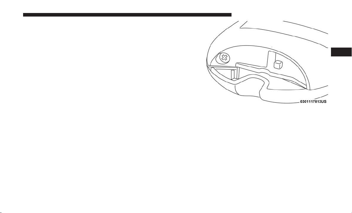
To Unlock/Enter The Liftgate
The liftgate passive entry unlock feature is built into
liftgate handle release. With a valid Passive Entry key fob
within 5ft (1.5m) of the liftgate, push the electronic liftgate
release to open with one fluid motion.
To Lock The Liftgate
With a valid Passive Entry key fob within 5ft (1.5m) of the
liftgate, push the passive entry lock button located to the
left of liftgate handle release.
3

42 GETTING TO KNOW YOUR VEHICLE
NOTE: The liftgate passive entry lock button will lock all
doors and the liftgate. The liftgate unlock feature is built
into the electronic liftgate release.
Electronic Liftgate Release/Liftgate Passive Entry Location
To Lock The Vehicle’s Doors And Liftgate
With one of the vehicle’s Passive Entry key fob within 5ft
(1.5m) of the driver or passenger front door handles, push
the Passive Entry lock button located on the outside door
handle.
Push The Door Handle Button To Lock
NOTE: DO NOT grab the door handle, when pushing the
door handle lock button. This could unlock the door(s).

GETTING TO KNOW YOUR VEHICLE 43
• The Passive Entry system will not operate if the key fob
battery is dead.
The vehicle doors can also be locked by using the lock
button located on the vehicle’s interior door panel.
Automatic Unlock Doors On Exit
The doors will unlock automatically on vehicles with
power door locks if:
1. The Automatic Unlock Doors On Exit feature is enabled.
2. All doors are closed.
3
DO NOT Grab The Door Handle When Locking
NOTE:
• After pushing the door handle button, you must wait
two seconds before you can lock or unlock the doors,
using either Passive Entry door handle. This is done to
allow you to check if the vehicle is locked by pulling the
door handle without the vehicle reacting and unlocking.
• If Passive Entry is disabled using the Uconnect System,
the key protection described in ⬙Preventing Inadvertent
Locking of Passive Entry key fob in Vehicle⬙ remains
active/functional.
3. The transmission gear selector was not in PARK, then is
placed in PARK.
4. Any door is opened.
Auto Relocking
The auto door lock feature default condition is enabled.
When enabled, the door locks will lock automatically when
the vehicle’s speed exceeds 15 mph (24 km/h). The auto
door lock feature can be enabled or disabled by an authorized dealer per written request of the customer. Please see
an authorized dealer for service.

44 GETTING TO KNOW YOUR VEHICLE
Child-Protection Door Lock System — Rear Doors
To provide a safer environment for small children riding in
the rear seats, the rear doors are equipped with a ChildProtection Door Lock system.
To use the system, open each rear door, use a flat blade
screwdriver (or emergency key) and rotate the dial to the
lock or unlock position. When the system on a door is
engaged, that door can only be opened by using the
outside door handle even if the inside door lock is in the
unlocked position.
NOTE:
• When the child lock system is engaged, the door can be
opened only by using the outside door handle even
though the inside door lock is in the unlocked position.
• After engaging or disengaging the Child-Protection
Door Lock system, always test the door from the inside
to make certain it is in the desired position.
• For emergency exit with the system engaged, rotate the
door lock button until the lock indicator is hidden
(unlocked position), roll down the window, and open
the door with the outside door handle.
WARNING!
Avoid trapping anyone in a vehicle in a collision.
Remember that the rear doors can only be opened from
the outside when the Child-Protection locks are engaged (locked).
Child-Protection Door Lock Function

SEATS
Seats are a part of the Occupant Restraint System of the
vehicle.
WARNING!
• It is dangerous to ride in a cargo area, inside or
outside of a vehicle. In a collision, people riding in
these areas are more likely to be seriously injured or
killed.
• Do not allow people to ride in any area of your
vehicle that is not equipped with seats and seat belts.
In a collision, people riding in these areas are more
likely to be seriously injured or killed.
• Be sure everyone in your vehicle is in a seat and
using a seat belt properly.
GETTING TO KNOW YOUR VEHICLE 45
Manual Front Seat Adjustment — If Equipped
Manual Front Seat Forward/Rearward Adjustment
On models equipped with manual seats, the adjusting bar
is located at the front of the seats, near the floor.
Front Seat Adjustment
While sitting in the seat, lift up on the bar and move the
seat forward or rearward. Release the bar once you have
reached the desired position. Then, using body pressure,
move forward and rearward on the seat to be sure that the
seat adjusters have latched.
3

46 GETTING TO KNOW YOUR VEHICLE
WARNING!
• Adjusting a seat while driving may be dangerous.
Moving a seat while driving could result in loss of
control which could cause a collision and serious
injury or death.
Seats should be adjusted before fastening the seat
•
belts and while the vehicle is parked. Serious injury or
death could result from a poorly adjusted seat belt.
Manual Seat Height Adjustment
The driver’s and passenger’s seat height can be raised or
lowered by using a lever, located on the outboard side of
the seat. Pull upward on the lever to raise the seat height or
push downward on the lever to lower the seat height.
Seat Height Adjustment
Manual Front Seat Recline Adjustment
To adjust the seatback, lift the lever located on the outboard
side of the seat, lean back to the desired position and
release the lever. To return the seatback, lift the lever, lean
forward and release the lever.

GETTING TO KNOW YOUR VEHICLE 47
Manual Adjustment (Rear Seats)
WARNING!
Recline Lever
WARNING!
Do not ride with the seatback reclined so that the
shoulder belt is no longer resting against your chest. In
a collision you could slide under the seat belt, which
could result in serious injury or death.
Do not pile luggage or cargo higher than the top of the
seatback. This could impair visibility or become a
dangerous projectile in a sudden stop or collision.
3

48 GETTING TO KNOW YOUR VEHICLE
Rear Seat Forward/Rearward Adjustment — If Equipped
Lift up on the adjusting bar located at the front of the seat
near the floor and release it when the seat is at the desired
position. Then, using body pressure, move forward and
rearward on the seat to be sure that the seat adjusters have
latched.
Rear Seat Adjustment Bar
Rear Seat Recline Adjustment
The rear seatback also reclines for additional passenger
comfort. On vehicle’s equipped with a sliding rear seat,
pull on the pull strap while sitting in the rear seat to recline
the seatback.
Rear Sliding Seat Recliner Pull Strap

On vehicle’s equipped with a fixed rear seat, pull on the
handle located on the upper outboard side of the seatback.
Rear Fixed Seat Recline Lever
WARNING!
Do not ride with the seatback reclined so that the
shoulder belt is no longer resting against your chest. In
a collision you could slide under the seat belt, which
could result in serious injury or death.
GETTING TO KNOW YOUR VEHICLE 49
Power Seats — If Equipped
Some models may be equipped with a power driver’s seat
and/or power passenger seat. The power seat switch and
power seat recliner switch are located on the outboard side
of the seat near the floor. Use the power seat switch to
adjust seat height, angle, or forward/rearward position.
Use the power seat recline switch to adjust the angle of the
seat back.
Power Seat Switch
3

50 GETTING TO KNOW YOUR VEHICLE
Forward Or Rearward Adjustment
The seat can be adjusted both forward and rearward. Push
the seat switch forward or rearward, the seat will move in
the direction of the switch. Release the switch when the
desired position has been reached.
Height Adjustment
The height of the seats can be adjusted up or down. Pull
upward or push downward on the seat switch, the seat will
move in the direction of the switch. Release the switch
when the desired position is reached.
Tilt Adjustment
The angle of the seat cushion can be adjusted up or down.
Pull upward or push downward on the front of the seat
switch and the front of the seat cushion will move in the
direction of the switch.
Reclining The Seatback Forward Or Rearward
The seatback can be reclined both forward and rearward.
Push the seat recliner switch forward or rearward. The
seatback will move in the direction of the switch. Release
the switch when the desired position has been reached.
Power Seat Recliner Switch
WARNING!
Do not ride with the seatback reclined so that the
shoulder belt is no longer resting against your chest. In
a collision you could slide under the seat belt, which
could result in serious injury or death.

Power Lumbar — If Equipped
Vehicles equipped with power driver or passenger seats
may be equipped with power lumbar. The power lumbar
switch is located on the outboard side of the power seat.
Push the switch forward or rearward to increase or decrease the lumbar support. Push the switch upward or
downward to raise or lower the lumbar support.
Power Lumbar Switch
Driver Memory Seat — If Equipped
This feature allows the driver to store up to two different
memory profiles for easy recall through a memory switch.
GETTING TO KNOW YOUR VEHICLE 51
Each memory profile contains desired position settings for
the driver seat and side mirrors and a set of desired radio
station presets.
The memory switch is located on the driver’s side door
panel. The switch contains three buttons, a set (S) button to
activate the memory save function, memory button (1) and
memory button (2). The memory switch allows the driver
to recall either of the two pre-programmed memory profiles by pushing the appropriate number button on the
switch.
Driver Memory Switch
3

52 GETTING TO KNOW YOUR VEHICLE
Programming The Memory Feature
To create a new memory profile, perform the following:
NOTE: Saving a new memory profile will erase an existing
profile from memory.
1. Cycle the vehicle’s ignition to the ON/RUN position.
2. Adjust all memory profile settings to desired preferences (i.e., seat, side mirror and radio station presets).
3. Push and release the set (S) button on the memory
switch, then push memory button (1) within five seconds. The instrument cluster display will display which
memory position is being set.
If desired, a second memory profile can be stored into
memory as follows:
1. Cycle the vehicle’s ignition to the ON/RUN position.
2. Adjust all memory profile settings to desired preferences (i.e., seat, side mirror and radio station presets).
3. Push and release the set (S) button on the memory
switch, then push memory button (2) within five seconds. The instrument cluster display will display which
memory position is being set.
NOTE:
• Memory profiles can be set without the vehicle in PARK,
but the vehicle must be in PARK to recall a memory
profile.
• To set a memory profile to your key fob, refer to
“Linking And Unlinking The Remote Keyless Entry Key
Fob To Memory” in this section.
Linking And Unlinking The Remote Keyless Entry Key Fob To Memory
Your remote keyless entry key fob can be programmed to
recall one of two pre-programmed memory profiles with a
push of the unlock button on the key fob.
NOTE: Before programming your key fob you must select
the “Personal Settings Linked to Key Fob” feature through
the Uconnect system screen.
Refer to “Uconnect Settings” in “Multimedia” for further
information.
To program your key fob, perform the following:
1. Cycle the vehicle’s ignition to the OFF position.
2. Select the desired memory profile 1 or 2.

NOTE: If a memory profile has not already been set, refer
to ⬙Programming The Memory Feature⬙ in this section for
instructions on how to set a memory profile.
Push and release the set (S) button on the memory switch,
3.
then within five seconds push and release the button
labeled (1) or (2) accordingly. “Memory Profile Set” (1 or
2) will display in the instrument cluster display.
4. Push and release the lock button on the key fob within
10 seconds.
NOTE: Your key fob can be unlinked to your memory
settings by pushing the set (S) button, followed by pushing
the unlock button on the key fob within 10 seconds.
Memory Position Recall
NOTE: The vehicle must be in PARK to recall memory
positions. If a recall is attempted when the vehicle is not in
PARK, a message will display in the instrument cluster
display.
• To recall the memory settings for driver one, push
memory button number (1) or the unlock button on the
key fob linked to memory position 1.
• To recall the memory settings for driver two, push
memory button number (2) or the unlock button on the
key fob linked to memory position 2.
GETTING TO KNOW YOUR VEHICLE 53
A recall can be canceled by pushing any of the memory
buttons (S, 1, or 2) during a recall. When a recall is
canceled, the driver seat will stop moving. A delay of one
second will occur before another recall can be selected.
Easy Entry/Exit Seat — If Equipped
This feature provides automatic driver seat positioning to
enhance driver mobility when entering and exiting the
vehicle.
The distance the driver seat moves depends on where you
have the driver seat positioned when you cycle the vehicle’s ignition to the OFF position.
• When you cycle the vehicle’s ignition to the OFF position, the driver seat will move about 2.4 inches (60 mm)
rearward if the driver seat position is greater than or
equal to 2.7 inches (67.7 mm) forward of the rear stop.
The seat will return to its previously set position when
you cycle the vehicle’s ignition to the ACC or RUN
position.
• The Easy Entry/Easy Exit feature is disabled when the
driver seat position is less than 0.9 of an inch (22.7 mm)
forward of the rear stop. At this position, there is no
benefit to the driver by moving the seat for Easy Exit or
Easy Entry.
3

54 GETTING TO KNOW YOUR VEHICLE
Each stored memory setting will have an associated Easy
Entry and Easy Exit position.
NOTE: The Easy Entry/Exit feature is not enabled when
the vehicle is delivered from the factory. The Easy Entry/
Exit feature is enabled (or later disabled) through the
programmable features in the Uconnect system.
Refer to “Uconnect Settings/Customer Programmable Features” in “Multimedia” for further information.
Heated Seats — If Equipped
On some models, the front and rear seats may be equipped
with heaters located in the seat cushions and seat backs.
WARNING!
• Persons who are unable to feel pain to the skin
because of advanced age, chronic illness, diabetes,
spinal cord injury, medication, alcohol use, exhaustion or other physical condition must exercise care
when using the seat heater. It may cause burns even
at low temperatures, especially if used for long
periods of time.
(Continued)
WARNING! (Continued)
•
Do not place anything on the seat or seatback that
insulates against heat, such as a blanket or cushion.
This may cause the seat heater to overheat. Sitting in a
seat that has been overheated could cause serious burns
due to the increased surface temperature of the seat.
Front Heated Seats — If Equipped
The front heated seats control buttons are located within
the Uconnect system. You can gain access to the control
buttons through the climate screen or the controls screen.
• Press the heated seat button
setting on.
• Press the heated seat button
the LO setting on.
• Press the heated seat button
heating elements off.
If the HI-level setting is selected, the system will automatically switch to LO-level after approximately 60 minutes of
continuous operation. At that time, the display will change
from HI to LO, indicating the change. The LO-level setting
will turn off automatically after approximately 45 minutes.
once to turn the HI
a second time to turn
a third time to turn the

NOTE: The engine must be running for the heated seats to
operate.
Vehicles Equipped With Remote Start
On models that are equipped with remote start, the heated
seats can be programmed to come on during a remote start.
This feature can be programmed through the Uconnect
system. Refer to “Uconnect Settings” in “Multimedia” for
further information.
WARNING!
• Persons who are unable to feel pain to the skin
because of advanced age, chronic illness, diabetes,
spinal cord injury, medication, alcohol use, exhaustion or other physical condition must exercise care
when using the seat heater. It may cause burns even
at low temperatures, especially if used for long
periods of time.
• Do not place anything on the seat or seatback that
insulates against heat, such as a blanket or cushion.
This may cause the seat heater to overheat. Sitting in
a seat that has been overheated could cause serious
burns due to the increased surface temperature of the
seat.
GETTING TO KNOW YOUR VEHICLE 55
Rear Heated Seats — If Equipped
On some models, the two outboard rear seats are equipped
with heated seats. The heated seat switches for these seats
are located on the rear of the center console.
There are two heated seat switches that allow the rear
passengers to operate the seats independently. Amber
indicator lights in each switch indicate the level of heat in
use. Two indicator lights will illuminate for HI, one for LO
and none for OFF.
• Push the heated seat button
once to turn the HI
setting on.
• Push the heated seat button
a second time to turn
the LO setting on.
• Push the heated seat button
a third time to turn the
heating elements off.
NOTE:
• Once a heat setting is selected, heat will be felt within
two to five minutes.
• The engine must be running for the heated seats to
operate.
3

56 GETTING TO KNOW YOUR VEHICLE
When the HI-level setting is selected, the heater will
provide a boosted heat level during the first four minutes
of operation. Then, the heat output will drop to the normal
HI-level. If the HI-level setting is selected, the system will
automatically switch to LO-level after approximately 60
minutes of continuous operation. At that time, the number
of illuminated LEDs changes from two to one, indicating
the change. The LO-level setting will turn OFF automatically after approximately 45 minutes.
Front Ventilated Seats — If Equipped
Located in the seat cushion and seat back are fans that
draw the air from the passenger compartment and move
air through fine perforations in the seat cover to help keep
the driver and front passenger cooler in higher ambient
temperatures. The fans operate at two speeds, HI and LO.
The front ventilated seats control buttons are located
within the Uconnect system. You can gain access to the
control buttons through the climate screen or the controls
screen.
• Press the ventilated seat button
• Press the ventilated seat button
once to choose HI.
a second time to
choose LO.
• Press the ventilated seat button
a third time to turn
the ventilated seat off.
NOTE: The engine must be running for the ventilated seats
to operate.
Vehicles Equipped With Remote Start
On models that are equipped with remote start, the ventilated seats can be programmed to come on during a remote
start.
This feature can be programmed through the Uconnect
system. Refer to “Uconnect Settings” in “Multimedia” for
further information.
60/40 Split Folding Rear Seat With Fold-Flat Feature
To provide additional storage area, each rear seat can be
folded flat. This allows for extended cargo space and still
maintains some rear seating room.
NOTE: Prior to folding the rear seat, it may be necessary to
position the front seat to its mid-track position. Also, be
sure that the front seats are fully upright and positioned
forward. This will allow the rear seat to fold down easily.

WARNING!
• It is extremely dangerous to ride in a cargo area,
inside or outside of a vehicle. In a collision, people
riding in these areas are more likely to be seriously
injured or killed.
• Do not allow people to ride in any area of your
vehicle that is not equipped with seats and seat belts.
• Be sure everyone in your vehicle is in a seat and
using a seat belt properly.
GETTING TO KNOW YOUR VEHICLE 57
To Lower The Rear Seat
1. Lift the seatback release lever located on the upper outer
edge of the seat. If your vehicle is equipped with a
sliding rear seat, you can also pull the pull strap located
on the middle outer edge of the seat.
Rear Sliding Seat Release Lever And Pull Strap
3

58 GETTING TO KNOW YOUR VEHICLE
Rear Fixed Seat Release Lever
2. Fold the rear seatback completely forward.
NOTE: You may experience deformation in the seat cushion from the seat belt buckles if the seats are left folded for
an extended period of time. This is normal and by simply
placing the seats to the open position, over time the seat
cushion will return to its normal shape.
To Raise The Rear Seat
NOTE: If interference from the cargo area prevents the
seatback from fully locking, you will have difficulty returning the seat to its proper position.
Raise the seatback and lock it into place.
WARNING!
Be certain that the seatback is securely locked into
position. If the seatback is not securely locked into
position the seat will not provide the proper stability
for child seats and/or passengers. An improperly
latched seat could cause serious injury.
HEAD RESTRAINTS
Head restraints are designed to reduce the risk of injury by
restricting head movement in the event of a rear impact.
Head restraints should be adjusted so that the top of the
head restraint is located above the top of your ear.

WARNING!
• All occupants, including the driver, should not operate a vehicle or sit in a vehicle’s seat until the head
restraints are placed in their proper positions in
order to minimize the risk of neck injury in the event
of a crash.
• Head restraints should never be adjusted while the
vehicle is in motion. Driving a vehicle with the head
restraints improperly adjusted or removed could
cause serious injury or death in the event of a
collision.
NOTE: Do not reverse the head restraints (making the rear
of the head restraint face forward) in an attempt to gain
additional clearance to the back of your head.
Reactive Head Restraints — Front Seats
The front driver and passenger seats are equipped with
Reactive Head Restraints (RHR). In the event of a rear
impact, the RHRs will automatically extend forward minimizing the gap between the back of the occupant’s head
and the RHR.
GETTING TO KNOW YOUR VEHICLE 59
The RHRs will automatically return to their normal position following a rear impact. If the RHRs do not return to
their normal position, see your authorized dealer immediately.
To raise the head restraint, pull upward on the head
restraint. To lower the head restraint, push the adjustment
button, located at the base of the head restraint, and push
downward on the head restraint.
NOTE: To remove the head restraint, raise it as far as it can
go. Then, push the release button and the adjustment
button at the base of each post while pulling the head
restraint up. Seatback angle may need to be adjusted to
fully remove the head restraint. To reinstall the head
restraint, put the head restraint posts into the holes and
push downward. Then adjust the head restraint to the
appropriate height.
3

60 GETTING TO KNOW YOUR VEHICLE
WARNING! (Continued)
• ALL the head restraints MUST be reinstalled in the
vehicle to properly protect the occupants. Follow the
re-installation instructions above prior to operating
the vehicle or occupying a seat.
• Do not place items over the top of the Reactive Head
Restraint, such as coats, seat covers or portable DVD
players. These items may interfere with the operation of the Reactive Head Restraint in the event of a
collision and could result in serious injury or death.
Front Head Restraint
1 — Release Button
2 — Adjustment Button
WARNING!
• A loose head restraint thrown forward in a collision
or hard stop could cause serious injury or death to
occupants of the vehicle. Always securely stow removed head restraints in a location outside the
occupant compartment.
(Continued)
Rear Head Restraints
The rear outboard and center head restraints have two
positions: up and down. When the center seat is being
occupied the head restraint should be in the raised position. When there is no occupant in the center seat, the head
restraint can be lowered for maximum visibility for the
driver.
To raise the head restraint, pull upward on the head
restraint. To lower the head restraint, push the adjustment
button, located at the base of the head restraint, and push
downward on the head restraint.

NOTE: To remove the head restraint, raise it as far as it can
go. Then, push the release button and the adjustment
button at the base of each post while pulling the head
restraint up. To reinstall the head restraint, put the head
restraint posts into the holes and push downward. Then,
adjust the head restraint to the appropriate height.
GETTING TO KNOW YOUR VEHICLE 61
3
Center Head Restraint
1 — Adjustment Button
2 — Release Button
WARNING!
Outboard Head Restraint
1 — Release Button
2 — Adjustment Button
ALL the head restraints MUST be reinstalled in the
vehicle to properly protect the occupants. Follow the
re-installation instructions above prior to operating the
vehicle or occupying a seat.

62 GETTING TO KNOW YOUR VEHICLE
STEERING WHEEL
Tilt/Telescoping Steering Column
This feature allows you to tilt the steering column upward
or downward. It also allows you to lengthen or shorten the
steering column. The tilt/telescoping lever is located below
the steering wheel at the end of the steering column.
Tilt/Telescoping Lever
To unlock the steering column, push the control handle
downward (toward the floor). To tilt the steering column,
move the steering wheel upward or downward as desired.
To lengthen or shorten the steering column, pull the
steering wheel outward or push it inward as desired. To
lock the steering column in position, push the control
handle upward until fully engaged.
WARNING!
Do not adjust the steering column while driving.
Adjusting the steering column while driving or driving with the steering column unlocked, could cause the
driver to lose control of the vehicle. Failure to follow
this warning may result in serious injury or death.
Heated Steering Wheel — If Equipped
The steering wheel contains a heating element that helps
warm your hands in cold weather. The heated steering
wheel has only one temperature setting. Once the heated
steering wheel has been turned on, it will stay on for an
average of 80 minutes before automatically shutting off.
This time will vary based on environmental temperatures.
The heated steering wheel can shut off early or may not
turn on when the steering wheel is already warm.
The heated steering wheel control button is located within
the Uconnect system. You can gain access to the control
button through the climate screen or the controls screen.
• Press the heated steering wheel button
the heating element on.
once to turn

• Press the heated steering wheel button
a second time
to turn the heating element off.
NOTE: The engine must be running for the heated steering
wheel to operate.
Vehicles Equipped With Remote Start
On models that are equipped with remote start, the heated
steering wheel can be programmed to come on during a
remote start through the Uconnect system. Refer to
“Uconnect Settings” in “Multimedia” for further information.
WARNING!
• Persons who are unable to feel pain to the skin
because of advanced age, chronic illness, diabetes,
spinal cord injury, medication, alcohol use, exhaustion, or other physical conditions must exercise care
when using the steering wheel heater. It may cause
burns even at low temperatures, especially if used
for long periods.
• Do not place anything on the steering wheel that
insulates against heat, such as a blanket or steering
wheel covers of any type and material. This may
cause the steering wheel heater to overheat.
GETTING TO KNOW YOUR VEHICLE 63
MIRRORS
Inside Day/Night Mirror — If Equipped
The mirror head can be adjusted up, down, left, and right
for various drivers. The mirror should be adjusted to center
on the view through the rear window.
Headlight glare from vehicles behind you can be reduced
by moving the small control under the mirror to the night
position (toward the rear of the vehicle). The mirror should
be adjusted while set in the day position (toward the
windshield).
Adjusting Rearview Mirror
3

64 GETTING TO KNOW YOUR VEHICLE
NOTE: The vehicle is equipped with either a single ball
joint mirror or a two ball adjustable prism mirror.
• The single ball joint is a twist-on mirror that has a fixed
position at the windshield. The mirror installs on the
windshield button with a counterclockwise rotation and
requires no tools for mounting.
• The two ball joint is mounted to a tombstone button on
the windshield with a set screw. Tools are required for
mounting and dismounting.
Electrochromic Mirror — If Equipped
A single ball joint mirror is provided in the vehicle. It is a
twist on mirror that has a fixed position at the windshield.
The mirror installs on the windshield button with a counterclockwise rotation and requires no tools for mounting.
The mirror head can be adjusted up, down, left, and right
for various drivers. The mirror should be adjusted to center
on the view through the rear window.
Automatic Dimming Button
NOTE: The automatic dimming feature is disabled when
the vehicle is in REVERSE to improve rear view viewing.
The automatic dimming feature can be turned on or off
through the touchscreen, or using the power button on the
base of the mirror.
• Press the mirror dimmer button once to turn the feature
on.
• Press the mirror dimmer button a second time to turn
the feature off.

CAUTION!
To avoid damage to the mirror during cleaning, never
spray any cleaning solution directly onto the mirror.
Apply the solution onto a clean cloth and wipe the
mirror clean.
Outside Mirrors
To receive maximum benefit, adjust the outside mirror(s) to
center on the adjacent lane of traffic and a slight overlap of
the view obtained from the inside mirror.
NOTE: The passenger side convex outside mirror will give
a much wider view to the rear, and especially of the lane
next to your vehicle.
GETTING TO KNOW YOUR VEHICLE 65
Power Mirrors
The power mirror switches are located on the driver’s door
trim panel.
3
WARNING!
Vehicles and other objects seen in an outside convex
mirror will look smaller and farther away than they
really are. Relying too much on side convex mirrors
could cause you to collide with another vehicle or other
object. Use your inside mirror when judging the size or
distance of a vehicle seen in a side convex mirror.
Power Mirror Switches
1 — Mirror Direction Control
2 — Left And Right Mirror Select

66 GETTING TO KNOW YOUR VEHICLE
Heated Mirrors — If Equipped
These mirrors are heated to melt frost or ice. This
feature will be activated whenever you turn on
the rear window defroster (if equipped).
Refer to “Climate Controls” in “Getting To Know Your
Vehicle” for further information.
Illuminated Vanity Mirrors
An illuminated vanity mirror is on each sun visor. To use
the mirror, rotate the sun visor down and swing the mirror
cover upward. The lights will turn on automatically. Closing the mirror cover will turn off the light.
Illuminated Vanity Mirror
Sun Visor “Slide-On-Rod” Feature
The sun visor “Slide-On-Rod” feature allows for additional
flexibility in positioning the sun visor to block out the sun.
1. Fold down the sun visor.
2. Unclip the visor from the center clip.
3. Pull the sun visor toward the inside rearview mirror to
extend it.

EXTERIOR LIGHTS
Multifunction Lever
The multifunction lever controls the operation of the turn
signals, headlight beam selection and passing lights. The
multifunction lever is located on the left side of the steering
column.
Multifunction Lever
GETTING TO KNOW YOUR VEHICLE 67
Headlight Switch
The headlight switch is located on the left side of
the instrument panel. This switch controls the op-
eration of the headlights, parking lights, automatic
headlights — if equipped, instrument panel lights, instrument panel light dimming, interior lights, and fog lights —
if equipped.
Headlight Switch
Rotate the headlight switch clockwise to the first detent for
parking light and instrument panel light operation. Rotate
the headlight switch to the second detent for headlight,
parking light and instrument panel light operation.
3

68 GETTING TO KNOW YOUR VEHICLE
Daytime Running Lights (DRL) — If Equipped
The Daytime Running Lights will turn on when the engine
is started and remain on unless the headlamps are turned
on, the parking brake is applied, or the engine is shut OFF.
NOTE: If allowed by law, in the country in which the
vehicle was purchased, the Daytime Running Lights can be
turned on and off using the Uconnect System, refer to
“Uconnect Settings” in “Multimedia” for further information.
High/Low Beam Switch
Push the multifunction lever away from you to switch the
headlights to high beam. Pull the multifunction lever
toward you to switch the headlights back to low beam.
Automatic High Beam Headlamp Control — If Equipped
The Automatic High Beam Headlamp Control system
provides increased forward lighting at night by automating high beam control through the use of a digital camera
mounted on the inside rearview mirror. This camera detects vehicle specific light and automatically switches from
high beams to low beams until the approaching vehicle is
out of view.
NOTE:
• The multifunction lever must be in the high beam
position in order to activate the Automatic High Beams.
• The Automatic High Beam Headlamp Control can be
turned on or off using the Uconnect System. Refer to
“Uconnect Settings” in “Multimedia” for further information.
• Broken, muddy, or obstructed headlights and taillights
of vehicles in the field of view will cause headlights to
remain on longer (closer to the vehicle). Also, dirt, film,
and other obstructions on the windshield or camera lens
will cause the system to function improperly.
Flash-To-Pass
You can signal another vehicle with your headlights by
lightly pulling the multifunction lever toward you. This
will cause the high beam headlights to turn on, and remain
on, until the lever is released.
Automatic Headlights — If Equipped
This system automatically turns the headlights on or off
according to ambient light levels. To turn the system on,
rotate the headlight switch clockwise to the last detent
(AUTO position) for automatic headlight operation. When

the system is on, the headlight time delay feature is also on.
This means the headlights will stay on for up to 90 seconds
after you place the ignition into the OFF position. To turn
the automatic system off, move the headlight switch out of
the AUTO position.
NOTE: The engine must be running before the headlights
will come on in the automatic mode.
Headlights On With Wipers (Available With Automatic Headlights Only)
When this feature is active, the headlights will turn on after
the wipers are turned on if the headlight switch is placed in
the AUTO position and programmable feature is set to ON.
In addition, the headlights will turn off when the wipers
are turned off if they were turned on by this feature.
NOTE: The Headlights On with Wipers feature can be
turned on or off using the Uconnect System. Refer to
“Uconnect Settings/Customer Programmable Features” in
“Multimedia” for further information.
Headlight Time Delay
This feature provides the safety of headlight illumination
for up to 90 seconds (programmable) when leaving your
vehicle in an unlit area.
GETTING TO KNOW YOUR VEHICLE 69
To activate the delay feature, place the ignition in the OFF
position while the headlights are still on. Then, turn off the
headlights within 45 seconds. The delay interval begins
when the headlight switch is turned off.
NOTE: The headlight delay feature is automatically activated if the customer leaves the headlight switch in the
AUTO position while the ignition is placed in the OFF
position.
If you turn the headlights or parking lights on, or place the
ignition in ACC or RUN, the system will cancel the delay.
If you turn the headlights off before the ignition, they will
turn off in the normal manner.
NOTE:
• The lights must be turned off within 45 seconds of
placing the ignition in the OFF position to activate this
feature.
• The headlight delay time is programmable using the
Uconnect System, refer to “Uconnect Settings” in “Multimedia” for further information.
3

70 GETTING TO KNOW YOUR VEHICLE
Lights-On Reminder
If the headlights or parking lights are on after the ignition
is in the OFF position, a chime will sound to alert the driver
when the driver’s door is opened.
Fog Lights — If Equipped
The front fog light switch is built into the headlight switch.
Fog Light Switch
To activate the front fog lights, turn on the parking lights or
the low beam headlights and push the headlight switch. To
turn off the front fog lights, either push the headlight
switch a second time or turn off the headlight switch.
An indicator light in the instrument cluster illumi-
nates when the fog lights are turned on.
NOTE: The fog lights will operate with the low beam
headlights or parking lights on. However, selecting the
high beam headlights will turn off the fog lights.
Turn Signals
Move the multifunction lever up or down and the arrows on
each side of the instrument cluster display will flash to show
proper operation of the front and rear turn signal lights.
NOTE:
• If either light remains on and does not flash, or there is
a very fast flash rate, check for a defective LED turn
signal in the headlamp. Please see an authorized dealer
for service.
• A “Turn Signal On” message will appear in the instru-
ment cluster display and a continuous chime will sound
if the vehicle is driven more than 1 mile (1.6 km) with
either turn signal on.
• When the Daytime Running Lights are on and a turn
signal is activated, the Daytime Running Lamp will turn
off on the side of the vehicle in which the turn signal is
flashing. The Daytime Running Lamp will turn back on
when the turn signal is turned off.

Lane Change Assist — If Equipped
Tap the multifunction lever up or down once, without
moving beyond the detent, and the turn signal (right or
left) will flash three times then automatically turn off.
Battery Saver
To protect the life of your vehicle’s battery, load shedding
is provided for both the interior and exterior lights.
If the ignition is OFF and any door is left ajar for 10 minutes
or the dimmer control is rotated all the way up to the dome
on position for 10 minutes, the interior lights will automatically turn off.
NOTE: Battery saver mode is canceled if the ignition is
ON.
If the headlights remain on while the ignition is cycled OFF,
the exterior lights will automatically turn off after eight
minutes. If the headlights are turned on and left on for
eight minutes while the ignition is OFF, the exterior lights
will automatically turn off.
GETTING TO KNOW YOUR VEHICLE 71
INTERIOR LIGHTS
The interior lights come on when a door is opened.
To protect the battery, the interior lights will turn off
automatically 10 minutes after the ignition is placed in the
OFF position. This will occur if the interior lights were
switched on manually or are on because a door is open.
The Battery Protection also includes the glove compartment light and the cargo light. To restore interior light
operation after automatic battery protection is enabled
(Lights Off), either place the ignition in the ON/RUN
position or cycle the light switch.
3

72 GETTING TO KNOW YOUR VEHICLE
Interior Courtesy Lights
Front Map/Reading Lights
The front map/reading lights are mounted in the overhead
console. Each light can be turned on by pushing a switch
on either side of the console. To turn the lights off, push the
switch a second time. These lights also turn on when a door
is opened, or when the unlock button on the key fob is
pushed, or when the dimmer control is turned completely
upward to the second detent.
Front Map/Reading Light Switches
Instrument Panel Dimmer Control
The instrument panel dimmer control is part of the headlight switch and is located on the driver’s side of the
instrument panel.
With the parking lights or headlights on, rotating the
instrument panel dimmer control upward will increase the
brightness of the instrument panel lights and lighted
cupholders — if equipped.
Instrument Panel Dimmer

Dome Light Position
Rotate the instrument panel dimmer control completely
upward to the second detent to turn on the interior lights.
The interior lights will remain on when the instrument
panel dimmer control is in this position.
Ambient Light Control — If Equipped
Rotate the ambient dimmer control upward or downward
to increase or decrease the brightness of the ambient light
located in the overhead console, door handle lights, under
I/P lights, door map pocket lights, and cubby bin lights.
GETTING TO KNOW YOUR VEHICLE 73
Interior Light Defeat (Off)
Rotate the instrument panel dimmer control to the extreme
bottom (O) off position. The interior lights will remain off
when the doors are open.
Parade Mode (Daytime Brightness Feature)
Rotate the instrument panel dimmer control upward to the
first detent. This feature brightens all text displays such as
the odometer, instrument cluster display, and radio when
the position lights or headlights are on.
3
Ambient Light/Door Handle Light Dimmer

74 GETTING TO KNOW YOUR VEHICLE
WINDSHIELD WIPERS AND WASHERS
The windshield wiper/washer controls are located on the
windshield wiper/washer lever on the right side of the
steering column. The front wipers are operated by rotating
a switch, located on the end of the lever. For information on
the rear wiper/washer, refer to “Rear Window Features” in
this section.
Windshield Wiper Operation
Rotate the end of the lever to one of the first four detent
positions for intermittent settings, the fifth detent for low
wiper operation and the sixth detent for high wiper operation.
Windshield Wiper Operation
CAUTION!
Windshield Wiper/Washer Lever
Always remove any buildup of snow that prevents the
windshield wiper blades from returning to the “park”
position. If the windshield wiper switch is turned off,
and the blades cannot return to the “park” position,
damage to the wiper motor may occur.

Windshield Washer Operation
To use the washer, pull the lever rearward toward you and
hold while spray is desired. If the lever is pulled while in
the intermittent setting, the wipers will turn on and operate
for several wipe cycles after the lever is released, and then
resume the intermittent interval previously selected.
Windshield Washer Operation
If the lever is pulled while the wipers are in the off position,
the wipers will operate for several wipe cycles, then turn
off.
GETTING TO KNOW YOUR VEHICLE 75
WARNING!
Sudden loss of visibility through the windshield could
lead to a collision. You might not see other vehicles or
other obstacles. To avoid sudden icing of the windshield during freezing weather, warm the windshield
with the defroster before and during windshield
washer use.
Mist
Use the Mist feature when weather conditions make occasional usage of the wipers necessary. Push the lever upward to the MIST position and release for a single wiping
cycle.
3

76 GETTING TO KNOW YOUR VEHICLE
NOTE: The mist feature does not activate the washer
pump; therefore, no washer fluid will be sprayed on the
windshield. The wash function must be used in order to
spray the windshield with washer fluid.
Intermittent Wiper Operation
NOTE: If the vehicle is moving less than 10 mph
(16 km/h), delay times will be doubled.
Mist Control
Intermittent Wiper System
Use one of the four intermittent wiper settings when
weather conditions make a single wiping cycle, with a
variable delay between cycles, desirable. At driving speeds
above 10 mph (16 km/h), the delay can be regulated from
a maximum of approximately 18 seconds between cycles
(first detent), to a cycle every one second (fourth detent).
Rain Sensing Wipers — If Equipped
This feature senses rain or snowfall on the windshield and
automatically activates the wipers for the driver. The
feature is especially useful for road splash or overspray
from the windshield washers of the vehicle ahead. Rotate
the end of the multifunction lever to one of four settings to
activate this feature.

The sensitivity of the system can be adjusted with the
multifunction lever. Wiper delay position one is the least
sensitive, and wiper delay position four is the most sensitive.
NOTE: Setting three should be used for normal rain
conditions.
Settings one and two can be used if the driver desires less
wiper sensitivity. Setting four can be used if the driver
desires more sensitivity. Place the wiper switch in the OFF
position when not using the system.
NOTE:
• The Rain Sensing feature will not operate when the
wiper switch is in the low or high-speed position.
• The Rain Sensing feature may not function properly
when ice or dried salt water is present on the windshield.
• Use of Rain-X or products containing wax or silicone
may reduce Rain Sensing performance.
• The Rain Sensing feature can be turned on and off using
the Uconnect System, refer to “Uconnect Settings” in
“Multimedia” for further information.
GETTING TO KNOW YOUR VEHICLE 77
The Rain Sensing system has protection features for the
wiper blades and arms, and will not operate under the
following conditions:
• Low Ambient Temperature — When the ignition is first
turned ON, the Rain Sensing system will not operate
until the wiper switch is moved, vehicle speed is greater
than 3 mph (5 km/h) or the outside temperature is
greater than 32°F (0°C).
• Transmission In NEUTRAL Position — When the igni-
tion is ON, and the automatic transmission is in the
NEUTRAL position, the Rain Sensing system will not
operate until the wiper switch is moved, vehicle speed is
greater than 3 mph (5 km/h) or the gear selector is
moved out of the NEUTRAL position.
Remote Start Mode Inhibit — On vehicles equipped with
Remote Starting system, Rain Sensing wipers are not
operational when the vehicle is in the remote start mode.
Once the operator is in the vehicle and has placed the
ignition switch in the RUN position, rain sensing wiper
operation can resume, if it has been selected, and no other
inhibit conditions (mentioned previously) exist.
3

78 GETTING TO KNOW YOUR VEHICLE
Rear Window Wiper/Washer
The rear wiper/washer controls are located on the windshield wiper/washer lever on the right side of the steering
column. The rear wiper/washer is operated by rotating a
switch, located at the middle of the lever.
Rear Wiper/Washer Control
Rotate the center portion of the lever upward to the
first detent for intermittent operation and to the
second detent for continuous rear wiper operation.
To use the washer, push the lever forward and
hold while spray is desired. If the lever is pushed
while in the intermittent setting, the wiper will
turn on and operate for several wipe cycles after the end of
the lever is released, and then resume the intermittent
interval previously selected.
If the lever is pushed while the wiper is in the off position,
the wiper will operate for several wipe cycles, then turn off.
NOTE: As a protective measure, the pump will stop if the
switch is held for more than 20 seconds. Once the lever is
released the pump will resume normal operation.
If the rear wiper is operating when the ignition is turned
OFF, the wiper will automatically return to the “park”
position.
Windshield Wiper De-Icer — If Equipped
Your vehicle may be equipped with a Windshield Wiper
De-Icer feature that may be activated under the following
conditions:
• Activation By Front Defrost — The Windshield Wiper
De-Icer shall be activated automatically in the case of a
cold weather manual start with full front defrost, and
when the ambient temperature is below 33° F (0.6° C).

• Activation By Rear Defrost — The Windshield Wiper
De-Icer shall be activated automatically when the rear
defrost is turned on and when the ambient temperature
is below 33° F (0.6° C).
• Activation By Remote Start Operation — When remote
start is active and the outside ambient temperature is
less than 33° F (0.6° C), the Windshield Wiper De-Icer
shall be enabled. On exiting remote start resume previous operation except, if the Windshield Wiper De-Icer
timer and operation shall continue.
GETTING TO KNOW YOUR VEHICLE 79
CLIMATE CONTROLS
Manual Climate Control Without A Touchscreen
Overview
The controls for the manual heating and air conditioning
system in this vehicle consist of a series of outer rotary
dials and inner push knobs. These comfort controls can be
set to obtain desired interior conditions.
Manual Climate Controls Without A Touchscreen
3

80 GETTING TO KNOW YOUR VEHICLE
Manual Climate Control Without A Touchscreen Descriptions
Icon Description
Blower Control
Use this control to regulate the amount of air forced through the system in any mode you select.
The blower speed increases as you move the control clockwise from the off position.
Temperature Control
Use this control to regulate the temperature of the air inside the passenger compartment. Rotating the knob counterclockwise, from top center into the blue area of the scale, indicates cooler
temperatures. Rotating the knob clockwise, into the red area, indicates warmer temperatures.
Modes Control Knob
Turn the knob to adjust airflow distribution. The airflow distribution mode can be adjusted so
air comes from the instrument panel outlets, floor outlets, defrost outlets and demist outlets.
Panel Mode
Bi-Level Mode
Panel Mode
Air comes from the outlets in the instrument panel. Each of these outlets can be individually
adjusted to direct the flow of air. The air vanes of the center outlets and outboard outlets can be
moved up and down or side to side to regulate airflow direction. There is a shut off wheel located below the air vanes to shut off or adjust the amount of airflow from these outlets.
Bi-Level Mode
Air comes from the instrument panel outlets and floor outlets. A slight amount of air is directed
through the defrost and side window demister outlets.
NOTE: Bi-Level mode is designed under comfort conditions to provide cooler air out of the
panel outlets and warmer air from the floor outlets.

Icon Description
Floor Mode
Floor Mode
Air comes from the floor outlets. A slight amount of air is directed through the defrost and side
window demister outlets.
GETTING TO KNOW YOUR VEHICLE 81
3
Mix Mode
Mix Mode
Air is directed through the floor, defrost, and side window demister outlets. This setting works
best in cold or snowy conditions that require extra heat to the windshield. This setting is good
for maintaining comfort while reducing moisture on the windshield.
A/C Button
Push the A/C button to engage the Air Conditioning (A/C). A LED will illuminate when the
A/C system is engaged.
MAX A/C Setting
Turn the temperature control knob to the MAX Air Conditioning (A/C) setting to engage MAX
Air Conditioning (A/C). This is the coldest setting.
Recirculation Button
Press and release this button on the touchscreen, or push the button on the faceplate, to change
the system between recirculation mode and outside air mode. Recirculation can be used when
outside conditions, such as smoke, odors, dust, or humidity are present. Recirculation can be
used in all modes. The A/C can be deselected manually without disturbing the mode control
selection. Continuous use of the Recirculation mode may make the inside air stuffy and window
fogging may occur. Extended use of this mode is not recommended.

82 GETTING TO KNOW YOUR VEHICLE
Icon Description
Front Defrost Setting
Turn the Mode Control knob to the Front Defrost position. Air comes from the windshield and
side window demist outlets. Use Defrost mode with maximum temperature settings for best
windshield and side window defrosting and defogging.
Rear Defrost Button
Push and release the Rear Defrost Control button to turn on the rear window defroster and the
heated outside mirrors (if equipped). An indicator will illuminate when the rear window defroster is on. The rear window defroster automatically turns off after ten minutes.

Economy Mode
GETTING TO KNOW YOUR VEHICLE 83
• Activation By Rear Defrost
If ECONOMY mode is desired, push the A/C button to
turn off the LED indicator and the A/C compressor. Rotate
the temperature control knob to the desired temperature.
Also, make sure to select only Panel, Bi-Level, or Floor
modes.
Stop/Start System — If Equipped
While in an Autostop, the Climate Controls system may
automatically adjust airflow to maintain cabin comfort.
Customer settings will be maintained upon return to an
engine running condition.
Windshield Wiper De-icer — If Equipped
The windshield wiper de-icer is a heating element located
at the base of the windshield.
It operates automatically once the following conditions are
met:
• Activation By Front Defrost
The wiper de-icer activates automatically during a cold
weather manual start with full defrost, and when the
ambient temperature is below 33° F (0.6° C).
The wiper de-icer activates automatically when the Rear
Defrost is operating and the ambient temperature is below
33° F (0.6° C).
• Activation By Remote Start Operation
When the Remote Start is activated and the outside ambient temperature is less than 33° F (0.6° C) the windshield
wiper de-icer is activated. Upon exiting Remote Start, the
climate control functions will resume their previous operation except, if the de-icer is active, the de-icer timer and
operation will continue.
3

84 GETTING TO KNOW YOUR VEHICLE
Climate Controls With A Touchscreen Overview
Uconnect 3 With 5–inch Display With Manual Temperature Controls

GETTING TO KNOW YOUR VEHICLE 85
Uconnect 4 With 7–inch Display With Manual Temperature Controls
3

86 GETTING TO KNOW YOUR VEHICLE
Uconnect 4C/4C NAV With 8.4–inch Display With Manual Temperature Controls

GETTING TO KNOW YOUR VEHICLE 87
Uconnect 3 With 5–inch Display With Automatic Temperature Controls
3

88 GETTING TO KNOW YOUR VEHICLE
Uconnect 4 With 7–inch Display With Automatic Temperature Controls

GETTING TO KNOW YOUR VEHICLE 89
Uconnect 4C/4C NAV With 8.4–inch Display With Automatic Temperature Controls
3

90 GETTING TO KNOW YOUR VEHICLE
Climate Control With A Touchscreen Descriptions
Icon Description
MAX A/C Button
Press and release to change the current setting, the indicator illuminates when MAX A/C is on.
Performing this function again will cause the MAX A/C operation to switch into manual mode
and the MAX A/C indicator will turn off.
A/C Button
Press and release to change the current setting, the indicator illuminates when A/C is on.
Recirculation Button
Press and release this button on the touchscreen, or push the button on the faceplate, to change
the system between recirculation mode and outside air mode. Recirculation can be used when
outside conditions, such as smoke, odors, dust, or high humidity are present. Recirculation can
be used in all modes. The A/C can be deselected manually without disturbing the mode control
selection. Continuous use of the Recirculation mode may make the inside air stuffy and window
fogging may occur. Extended use of this mode is not recommended.
AUTO Button — If Equipped
Automatically controls the interior cabin temperature by adjusting airflow distribution and
amount. Toggling this button will cause the system to switch between manual mode and automatic modes. Refer to “Automatic Operation” in this section for more information.

Icon Description
Front Defrost Button
Press and release the touchscreen button, or push and release the button on the faceplate, to
change the current airflow setting to Defrost mode. The indicator illuminates when this feature
is on. Air comes from the windshield and side window demist outlets. When the defrost button
is selected, the blower level may increase. Use Defrost mode with maximum temperature settings for best windshield and side window defrosting and defogging. When toggling the front
defrost mode button, the climate system will return to the previous setting.
Rear Defrost Button
Push and release the button on the touchscreen, or push and release the button on the faceplate,
to turn on the rear window defroster and the heated outside mirrors (if equipped). An indicator
will illuminate when the rear window defroster is on. The rear window defroster automatically
turns off after ten minutes.
GETTING TO KNOW YOUR VEHICLE 91
3

92 GETTING TO KNOW YOUR VEHICLE
Icon Description
Uconnect 3
Driver and Passenger Temperature Up and Down Buttons
Provides the driver and passenger with independent temperature control. Push the red button
on the faceplate or touchscreen or press and slide the temperature bar towards the red arrow
button on the touchscreen for warmer temperature settings. Push the blue button on the face-
Uconnect 4/4C/4C
NAV
plate or touchscreen or press and slide the temperature bar towards the blue arrow button on
the touchscreen for cooler temperature settings.
NOTE: The numbers within the temperature display will only appear if the system is equipped
with an automatic climate control system.
SYNC Button — If Equipped
Press the SYNC button on the touchscreen to toggle the SYNC feature on/off. The SYNC indicator is illuminated when this feature is enabled. SYNC is used to synchronize the passenger temperature setting with the driver temperature setting. Changing the passenger’s temperature setting while in SYNC will automatically exit this feature.
Faceplate Knob
Blower Control
Blower Control is used to regulate the amount of air forced through the climate system. There
are seven blower speeds available. Adjusting the blower will cause automatic mode to switch to
manual operation. The speeds can be selected using either the blower control knob on the face-
Touchscreen
plate or the buttons on the touchscreen.

Icon Description
Buttons
• Faceplate: The blower speed increases as you turn the blower control knob clockwise from
the lowest blower setting. The blower speed decreases as you turn the blower control knob
counterclockwise.
• Touchscreen: Use the small blower icon to reduce the blower setting and the large blower
icon to increase the blower setting. Blower can also be selected by pressing the blower bar
area between the icons.
Panel Mode Panel Mode
Air comes from the outlets in the instrument panel. Each of these outlets can be individually
adjusted to direct the flow of air. The air vanes of the center outlets and outboard outlets can be
moved up and down or side to side to regulate airflow direction. There is a shut off wheel located below the air vanes to shut off or adjust the amount of airflow from these outlets.
Bi-Level Mode
Bi-Level Mode
Air comes from the instrument panel outlets and floor outlets. A slight amount of air is directed
through the defrost and side window demister outlets.
NOTE: Bi-Level mode is designed under comfort conditions to provide cooler air out of the
panel outlets and warmer air from the floor outlets.
Floor Mode
Floor Mode
Air comes from the floor outlets. A slight amount of air is directed through the defrost and side
window demister outlets.
GETTING TO KNOW YOUR VEHICLE 93
3

94 GETTING TO KNOW YOUR VEHICLE
Icon Description
Mix Mode
Mix Mode
Air is directed through the floor, defrost, and side window demister outlets. This setting works
best in cold or snowy conditions that require extra heat to the windshield. This setting is good
for maintaining comfort while reducing moisture on the windshield.
Climate Control OFF Button
Press and release this button to turn the Climate Controls off.
Climate Control Functions
A/C (Air Conditioning)
The Air Conditioning (A/C) button allows the operator to
manually activate or deactivate the air conditioning system. When the air conditioning system is turned on, cool
dehumidified air will flow through the outlets into the
cabin. For improved fuel economy, press the A/C button to
turn off the air conditioning and manually adjust the
blower and airflow mode settings. Also, make sure to select
only Panel, Bi-Level, or Floor modes.
NOTE:
• If fog or mist appears on the windshield or side glass,
select Defrost mode, and increase blower speed if
needed.
• If your air conditioning performance seems lower than
expected, check the front of the A/C condenser (located
in front of the radiator), for an accumulation of dirt or
insects. Clean with a gentle water spray from the front of
the radiator and through the condenser.

MAX A/C
MAX A/C sets the control for maximum cooling performance.
GETTING TO KNOW YOUR VEHICLE 95
Automatic Temperature Control (ATC) — If Equipped
Automatic Operation
Press and release to toggle between MAX A/C and the
prior settings. The button illuminates when MAX A/C is
on.
In MAX A/C, the blower level and mode position can be
adjusted to desired user settings. Pressing other settings
will cause the MAX A/C operation to switch to the selected
setting and MAX A/C to exit.
Recirculation
In cold weather, use of Recirculation mode may lead to
excessive window fogging. The Recirculation feature may
be unavailable (button on the touchscreen greyed out) if
conditions exist that could create fogging on the inside of
the windshield.
On systems with Manual Climate Controls, the Recirculation mode is not allowed in Defrost mode to improve
window clearing operation. Recirculation is disabled automatically if this mode is selected. Attempting to use
Recirculation while in this mode causes the LED in the
control button to blink and then turns off.
1. Push the AUTO button on the faceplate, or the AUTO
button on the touchscreen on the Automatic Temperature Control (ATC) Panel.
2. Next, adjust the temperature you would like the system
to maintain by adjusting the driver and passenger
temperature control buttons. Once the desired temperature is displayed, the system will achieve and automatically maintain that comfort level.
3. When the system is set up for your comfort level, it is
not necessary to change the settings. You will experience
the greatest efficiency by simply allowing the system to
function automatically.
3

96 GETTING TO KNOW YOUR VEHICLE
NOTE:
• It is not necessary to move the temperature settings for
cold or hot vehicles. The system automatically adjusts
the temperature, mode, and blower speed to provide
comfort as quickly as possible.
• The temperature can be displayed in U.S. or Metric units
by selecting the US/Metric customer-programmable feature. Refer to the “Uconnect Settings” in “Multimedia”
for further information.
To provide you with maximum comfort in the Automatic
mode during cold start-ups, the blower fan will remain on
low until the engine warms up. The blower will increase in
speed and transition into Auto mode.
Manual Operation Override
This system offers a full complement of manual override
features. The AUTO symbol in the front ATC display will
be turned off when the system is being used in the manual
mode.
Operating Tips
NOTE: Refer to the chart at the end of this section for
suggested control settings for various weather conditions.
Summer Operation
The engine cooling system must be protected with a
high-quality antifreeze coolant to provide proper corrosion
protection and to protect against engine overheating. OAT
coolant (conforming to MS.90032) is recommended.
Winter Operation
To ensure the best possible heater and defroster performance, make sure the engine cooling system is functioning
properly and the proper amount, type, and concentration
of coolant is used. Use of the Air Recirculation mode
during Winter months is not recommended, because it may
cause window fogging.
Vacation/Storage
Before you store your vehicle, or keep it out of service (i.e.,
vacation) for two weeks or more, run the air conditioning
system at idle for about five minutes, in fresh air with the
blower setting on high. This will ensure adequate system
lubrication to minimize the possibility of compressor damage when the system is started again.

Window Fogging
Vehicle windows tend to fog on the inside in mild, rainy,
and/or humid weather. To clear the windows, select Defrost or Mix mode and increase the front blower speed. Do
not use the Recirculation mode without A/C for long
periods, as fogging may occur.
CAUTION!
Failure to follow these cautions can cause damage to
the heating elements:
• Use care when washing the inside of the rear window. Do not use abrasive window cleaners on the
interior surface of the window. Use a soft cloth and a
mild washing solution, wiping parallel to the heating elements. Labels can be peeled off after soaking
with warm water.
• Do not use scrapers, sharp instruments, or abrasive
window cleaners on the interior surface of the window.
• Keep all objects a safe distance from the window.
GETTING TO KNOW YOUR VEHICLE 97
Outside Air Intake
Make sure the air intake, located directly in front of the
windshield, is free of obstructions, such as leaves. Leaves
collected in the air intake may reduce airflow, and if they
enter the plenum, they could plug the water drains. In
Winter months, make sure the air intake is clear of ice,
slush, and snow.
Cabin Air Filter
The climate control system filters out dust and pollen from
the air. Contact an authorized dealer to service your cabin
air filter, and to have it replaced when needed.
3

98 GETTING TO KNOW YOUR VEHICLE
Operating Tips Chart WINDOWS
Power Window Controls
The window controls on the driver’s door control all the
door windows.
1 — Front Driver ’s Side Power Window Switch
2 — Front Passenger ’s Side Power Window Switch
3 — Rear Passenger ’s Side Power Window Switch
4 — Rear Driver ’s Side Power Window Switch
Power Window Switches
 Loading...