

Page 1
57
company
a
Please refer to table A1 for max
Table: A1
Please read these instructions before
installation and retain for future reference
Installation Sheet
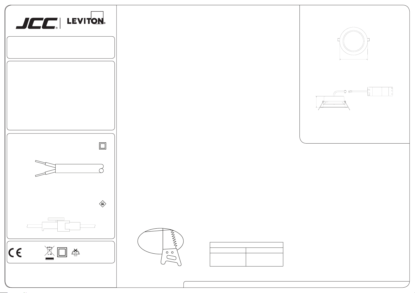
Prole & Dimensions
RAKULA LED
JC71274
Commercial Downlight
Light source:
Total circuit Wattage:
Beam angle:
Luminous ux:
Efcacy:
Colour temp:
Driver
100-240V~50/60Hz / Class II
Fig.2.
LIVE = BROWN
NEUTRAL = BLUE
Double insulated- no earth required
Luminaire
700mA/40VDC / Class III
Fig.3.
Integral LED
18W
90°
1570 lumens
87 LpcW
4000K
Ra:
81
Important Information
• It is recommended that luminaires are installed and tted by a qualied electrician
ensuring the installation complies with current IEE wiring regulations BS7671:2008 & local
building control.
• These products are designed for connection to a 100-240V 50/60Hz supply.
• Any broken or damaged parts should be replaced as soon as possible.
• JCC will not accept responsibility for any claims arising from a poor installation.
• The light source of this luminaire is not replaceable: when the light source reaches
its end of life, the whole of the luminaire must be replaced.
Important User Advice
• It is recommended that the ambient room temperature should not exceed 30°C.
• Ensure that there is adequate free air ventilation around the tting.
• The installation must not infringe on water pipes or any other electrical services.
• It may be necessary to uprate your MCBs to allow for increased inrush current.
• Always switch off mains supply before tting or servicing.
• This luminaire is suitable for indoor use only.
• Do not cover with insulation.
Installation
Check you have all the tools and accessories required to complete the installation correctly. Isolate the power before starting the installation.
1. Cut the mounting hole in the ceiling Refer to Fig.1. (JCC recommends that a sample hole is cut in a section of spare material to familiarize yourself with the
process).
2. Ensure there is a minimum of 75mm space around the tting. DO NOT COVER the tting with insulation.
3. Connect the mains supply to the Luminaire as per Fig.2. and then connect the driver to the luminaire as per g.3.
4. Turn on the power supply to test the tting. Once satised that the luminaire is functioning correctly, press the spring clips against the side of the luminaire
and t into the aperture.
NOTE: DO NOT carry out insulation tests with the Luminaire connected to the circuit. There are no serviceable parts. If any of the components fail or become
faulty, contact JCC Technical Support.
Warranty 2 Year as standard
No. of fittings linked per circuit
5 year extended warranty available(online registration required)
Please visit: jcc.co.uk/warranty
All dimensions in millimetres
Ø160
RoHS
Compliant IP20
BS EN ISO9001 - 2008
Registered Firm Certicate No. GB 1552
Drg No. JC71274-IS Issue: E - 02.02.16 - RCS
Ø135
Fig.1.
jcc.co.uk
Circuit Breaker Type
B Type 6 amp C Type 10 amp
18 31
JCC Lighting Aftersales Technical Support Helpline: 01243 838986 Customer Service Department: 01243 838999
Prior to registration the installer is asked to provide the following
information directly from the luminaire:
Product code:
Batch number:
The approved electrical installer must give details of their Part P
registration when installing products in domestic applications.
 Loading...