

Page 1

JBL Consumer Products,
Incorporated
240 Crossways Park West
Woodbury, NY 11797
8500 Balboa Boulevard
Northridge, CA 91329
800-645-7484
P/N 301227-001
A Harman International Company
Page 2

SYNTHESIS
THREE
SPEAKERS
OWNER’S
MANUAL
®
Page 3

INTRODUCTION ............................................................................................................2
SPEAKER PLACEMENT.................................................................................................3
CONNECTING THE SPEAKERS TO THE REST OF YOUR SYSTEM..............................7
FINE TUNING YOUR AUDIO SYSTEM...........................................................................8
TROUBLESHOOTING..................................................................................................16
SPECIFICATIONS.........................................................................................................17
1
CONTENTS
Page 4

INTRODUCTION
Congratulations on purchasing this JBL Synthesis Three home theater speaker. This
product represents the synthesis of everything that JBL has learned about the emotional power of audio and video in over fifty years of preeminence in the field. It sets
new benchmarks in the use of “high technology” and provides you with the experience
of being in some of the world’s greatest movie-houses and concert halls, right at
home! JBL’s Synthesis Three speaker systems feature the following:
THX ® LICENSED HOME AUDIO SYSTEM: When used with a Home THX controller
and amplifiers, your speaker system will deliver state-of-the-art THX home theater
experience to your home. You will hear in your home, exactly what the director and
sound engineer heard in the recording studio. The system will reproduce the audio
flawlessly and without distortion.
CINEMA/MUSIC SWITCHING: The Synthesis Three main speakers (S3M) utilize different combinations of transducers that are specifically chosen for playing cinema or
music. Via an electronic relay, the speaker mode can be switched, depending on
whether the surround processor is in the music or cinema mode. The result is a
speaker that reproduces all sources incredibly!
HIGH POWER COMPRESSION HORN: Horns are commonplace in movie theaters
across the world, because of their high power handling and well-defined high frequency output. The horns employed in Synthesis Three have very low distortion, and a
well controlled directivity, to put the dialogue at the center of the screen and the effects
all around you.
ACCURATE MID-BASS DRIVERS AND SUBWOOFERS: The 6-1/2 inch mid-bass
drivers incorporate fiberglass reinforced cones along with microcell laminate domes
and surrounds to provide tight and smooth midrange sounds without harshness, stridency, or listener fatigue. The pair of twelve inch high power subwoofers completes
the experience with earth shattering, deep bass.
PURE TITANIUM TWEETER: This tweeter provides well-defined high frequency output with low distortion, flat and smooth high frequency response, and no break-up in
the audio range.
2
Page 5
COMMON VOICING: Synthesis Three uses common voicing across the front three
channels. Since identical drivers are used, each speaker has the same tonal qualities,
thus as a sound is panned from one side to the other, there will be no change in timbre.
MAGNETIC SHIELDING: All front speakers are magnetically shielded, allowing you to
place them near video monitors without generating interference or distorting the picture.
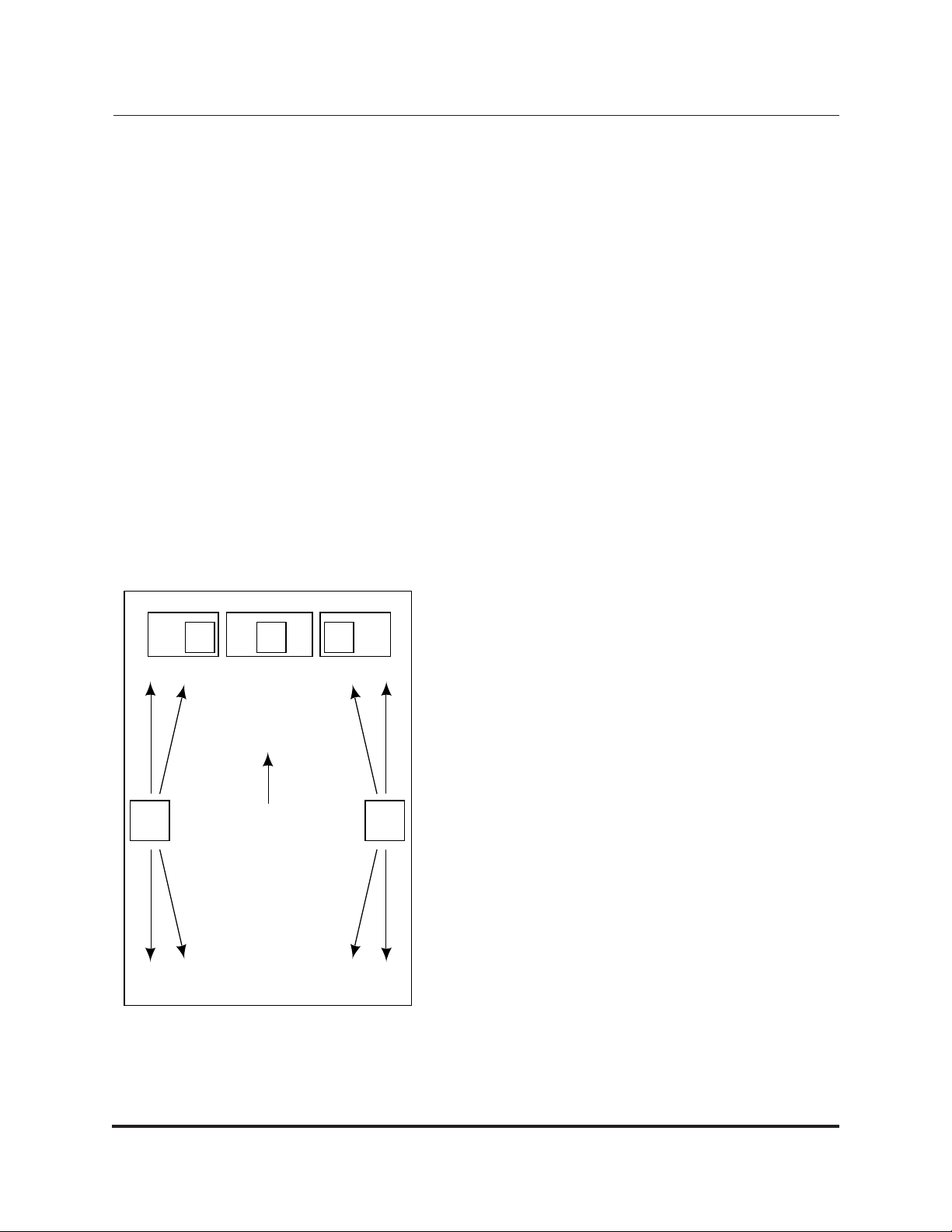
SPEAKER PLACEMENT
Positioning your speakers properly is critical in order to achieve the sonic performance of
a home theater. Please read the following sections to guide you in correct placement.
LEFT AND RIGHT SPEAKERS - If you have purchased the Synthesis Three Home
Media System, then the main speakers (model S3M) will serve as your left and right
speakers. If you have purchased the Synthesis Three Cinema Only System, or Cinema
Only Speaker Package, then the vertical center speakers (model S3VC) will serve as
your left and right speakers.
Since the left and right speakers have been
designed for maximum localization of sound, they
should be placed as close to the screen or television as possible, with the center of the horns at
about the same height on the screen as actors
would be, to aid in maintaining the illusion that the
actors’ voices are coming directly from their
mouths. Ideally, you want to have the speakers
about 45 degrees apart from each other, viewed
from the listening position.
“Toeing in” or turning in the speakers towards the
listening area is optional, and its effects can
depend on the room, so it is advisable to experiment with the speakers to see which orientation,
facing straight out or facing the center of the viewing area, yields the best results.
3
L RC
VIEWING
POSITION
FLOOR PLAN
Page 6

The speakers have been designed to integrate well with rear projection 35” and 45” tele-
vision sets. The subwoofers can be placed on both sides of the television set, with the
left and right speakers stacked on top. This arrangement lends itself nicely because it
places the center of the horns at approximately the desired height with the screen.
CENTER CHANNEL SPEAKERS
S3VC
If you have purchased the vertical center channel speaker (model S3VC), position it vertically in order to take advantage of its sound dispersion qualities. If you mount it horizontally, the S3VC will not work properly. If the speaker is being used with a perforated projection screen, then it should be mounted behind the center of the screen, in the same
plane as the left and right front speakers. In cases where the S3VC is being used with a
non-perforated screen, the speaker should be positioned above or below the screen. In
use with a rear projection television set, the vertical center channel could be placed
above or below based on mounting and visual constraints. If the center of the horn is
either above or below the center of the screen, the speaker should be tilted so that a line
from the center of the horn, perpendicular to the front surface extends to ear height in the
viewing position.
S3HC
If you have purchased the horizontal center channel speaker (model S3HC), then the suggested
location for it is on top of a television set. If the
center of the horn on top of the television set is
higher than where your ears would be while in the
viewing position, it is advisable to tilt the speaker
forward using the adjustable foot assembly in the
back. Tilt the speaker forward so that a line from
the center of the horn, perpendicular to the front
surface extends to ear height in the viewing position. Be careful while adjusting the height,
because large adjustments could make the speaker unstable on top of the television.
It is extremely important to maintain the vertical
distance between the horns in the center, left, and
4
SPEAKER PLACEMENT OPTIONS
HC
L
SCREEN
SUB SUB
R
OR
L
SCREEN
VC
R
SUBSUB
Page 7

right speakers. The horn in the center channel speaker should be no more than two
feet higher or lower than the horns in the left and right speakers. This preserves the
“localization integrity” of “sound pans”, in which the sound appears to move from left to
center to right. Having it also appear to go from high to low to high, or vice versa, can
destroy the illusion of such effects and should also be avoided. Use of speaker stands
can help achieve this goal.
SUBWOOFERS - The location of subwoofers is the most flexible aspect of placement.
The convention is to place them on or very near to the floor. The subwoofers can be
placed on both sides of the television set or projection screen, with the left and right
speakers stacked on top. If this arrangement is not feasible, then they can be placed
in the corners of the room. It is recommended that you experiment with the various
positions to see which suits you both sonically and aesthetically.
SURROUNDS - The ambient surround speakers work optimally
if they are placed as far back from the screen as the viewing
chairs are. If there are two rows of chairs, these speakers
should be placed between them.
The ambient surround speakers should not be placed to radiate
directly at the listeners. Rather, they should echo off the front
and rear walls, or optionally, off the ceiling, to create a sound
space that encloses the listener. The listeners should be located in a “null zone” in which no sound is directly radiating at
them from the ambient surrounds. Always make sure that the
null baffle (the side w/no speakers or speaker terminals) points
towards the listening area.
The ambient surround speakers should be placed higher than the seating area, at
least two feet above seated ear level.
The preferred method to mount the ambient surrounds is to put them directly on side
walls with brackets, or to stack them atop a column attached to the wall. This lets
each speaker radiate to the front and back of the room, and to reflect off the side walls.
There are a few instances in which the ambient surrounds would do better if mounted
on the ceiling rather than the walls. If one or both of the walls is “acoustically dead”,
5
Min. 2'-0"
Page 8

due to the presence of windows, fabrics, furniture, or other absorption, it may be necessary to turn the ambient speakers sideways, and instead of bracketing them in a
vertical orientation, hang or mount them from the ceiling in a horizontal orientation.
Although identical drivers are used on both sides of a surround speaker, it is important
to have a particular side facing the wall with the screen. Remove both grilles covering
the transducers and locate the side that has a port tube on it. Make sure that this side
faces the front of the room, or the wall that the screen is on. If you are mounting the
speakers on the wall, it is recommend that you use the mounting brackets that are supplied with them.
NOTE: Do not attempt to install any type of mounting bracket that is not supplied
with the speakers. Drilling holes in the product or improperly installing mounting
brackets may void your JBL warranty and cause a safety hazard.
A JBL factory authorized custom installer can suggest and install appropriate
brackets. Contact JBL and your installer/dealer for additional information.
6
Page 9

CONNECTING THE SPEAKERS TO THE REST OF YOUR SYSTEM
To connect the
Synthesis Three loudspeakers to the
receiver or power
amplifiers, use twoconductor insulated
speaker wire. We recommend #14 AWG
wire as a minimum
size. Your JBL dealer
can recommend suitable cables, or you
can buy this type of
wire at most hardware
stores.
The terminals on the back of the speakers accept both bare wire and dual banana
plugs, either of which will provide easy, secure connections.
PREPARING THE HOOKUP WIRE
1. First determine the distance between your amplifier and the most distant speaker in
each group (fronts, surrounds, subwoofers).
2. Now make the hookup wires for all speakers in each group this length, even if one
speaker is much closer to your amplifier than the other. This will help maintain proper
signal balance.
3. Strip of 3/8” of insulation from both ends of each conductor.
4. Twist each set of thin wires into a tightly-bunched spiral.
5. Now find a visual difference between the two conductors of each molded pair of
speaker wire. Differentiating marks can be a different color wire (copper or silver); a
strand of yarn in one conductor; thin, raised ribs on one part of the outer insulation; or
a printed marking on one part of the outer insulation. It doesn’t matter which of the two
strands go to the (+) and (-) on the speakers and amplifiers, as long as all speakers
7
S3M
OR
S3VC
S3S
AMBIENT
(-) (+)
*When used with a complete Synthesis Three system, the center amplifer (model S150) is operated in the mono bridged mode
S3VC
OR
S3HC
(-) (+)(-) (+) (-) (+)
LEFT AND RIGHT FRONT
LEFT
S300
(-) (+)
CENTER*
LEFT
S150
(-) (+)
SUBWOOFER
LEFT
S300
(-) (+)
AMBIENT
LEFT
S150
(-) (+)
AMPLIFIERS
LEFT
(-) (+)
LEFT
(-) (+)
LEFT
(-) (+)
LEFT
(-) (+)
S3M
OR
S3VC
(-) (+)(-) (+)
AMBIENT
(-) (+)
S3S
Page 10

are connected identically. Unscrew the binding post, insert the wire into the hole, and
retighten. If you are using banana plug type wire connectors, insert them directly into
the posts making sure the lug on the negative (-) side of the banana plug is placed into
the black binding post. For each channel, connect the red terminal on the loudspeaker to the red or (+) loudspeaker connection terminal on the amplifier and the black to
the black or (-). Connecting the loudspeakers this way ensures that they will be in
phase; that is, work together, not in opposition. Connecting the loudspeakers out of
phase will not damage them, but will result in less bass and poor imaging.
6. If you have purchased the Synthesis Three Home Media System, which utilizes the
S3M speakers for the left and right channels, it is necessary to connect the five pin din
cable (included) to each speaker. This cable is essential to the system, for it allows the
speakers to switch from the music mode to the cinema mode. Plug one end into the five
pin din jack (located above the speaker terminals) and the other end into the jack located on the power sequencer labeled “Speaker 1”. Do the same for the second speaker.
FINE TUNING YOUR AUDIO SYSTEM
ACOUSTICAL PROBLEMS IN LISTENING ROOMS
The Home THX Audio System addresses many of the problems common to high quality
reproduction of music or soundtracks in a home environment. For example, the dispersion
pattern of the front LCR speakers minimizes the effects of floor and ceiling reflections. Still,
there are many variables which are beyond the contr ol of a manufactur er. Room reflections
create spurious false images and “comb filter” interference effects which alter the tonality of
the system while degrading the localization of specific sounds. Larger rooms sustain echoes
which degrade dialog intelligibility and detail. All rooms have standing waves which emphasize certain frequencies at the expense of others, based on the dimensions of the room.
Other concerns include environmental noise, which is often greater than people realize. Although they might become accustomed to its presence and “tune it out,” it still
reduces the perceived low-level resolution of the system. In addition, the profound
bass capabilities of a Home THX Audio System can create distracting rattles which
lesser systems might never evoke.
It can be tempting to try to solve all of these problems with the indiscriminate use of
sound-absorbing products, but even this technique has its pitfalls.
All of these common acoustical problems will be addressed in this section. Once
again, these techniques are not necessary for a successful Home THX Audio System
installation. Rather, they are provided to solve occasional problems and to provide further enhancement possibilities.
8
Page 11

ROOM REFLECTIONS
The most troublesome room reflections are usually the early reflections of the LCR
speakers off the floor, ceiling and side walls. These reflections reach the listener’s ears
delayed with respect to direct sounds and blur the perceived image. They can also
degrade dialog intelligibility, through the same mechanisms.
The design of the THX LCR speakers minimizes the floor and ceiling reflections. As an
extra enhancement, it is often a good idea to place a thick, absorptive carpet between
the front speakers and the listening position, just to further reduce this primary reflection
from floors with hard surfaces. A rug made from wool will generally have more uniform
absorption characteristics than one made from synthetic fibers.
The THX LCR speakers have broad dispersion in the horizontal plane in order to ensure
a wide usable listening area. This design choice can induce reflections off of the side
walls, especially in installations where they are relatively close to the front speakers.
These reflections can be reduced simply by angling the left and right speakers inward
somewhat.
If giving the speakers some “toe-in” is not enough, the next step is the strategic placement of absorptive materials on the side walls. These range from commercially available
fiberglass and dense foam to heavy draperies and even large, overstuffed furniture. The
optimal position for these materials can be found with a small hand mirror and an assistant. Sit at the primary listening position and have the assistant slowly slide the mirror
along the wall. When
you can see any of the
front speakers reflected
in the mirror, mark the
wall at the mirror for later
placement of absorptive
material.
A variation of this
method is especially
helpful in rooms which
are already fairly “dead”
acoustically. Rather than
using absorptive material in rooms like these, try
using diffusion instead.
9
Page 12

Commercially built diffusers are available but large bookcases and irregularly shaped
furniture will also serve the same purpose. They reflect sounds in a highly randomized
way which effectively “scatters” the sound in all directions. Place the diffuser where you
would otherwise place the absorptive material (using the “mirror trick”), to break up the
first early reflections and scatter them randomly throughout the room.
Commercially available fiberglass, foam and diffusion panels may not be aesthetically
acceptable in many installations, particularly when the home theatre room serves multiple purposes. All of these materials can be covered with acoustically-transparent cloth
for design considerations. It is important that the cloth be acoustically transparent,
however, or else the effectiveness of the absorptive material will be greatly reduced.
The simplest test for this is to hold a large sample of the cloth in front of a speaker
playing the pink noise found in Chapter 6 of the
WOW! laserdisc. If you can move the
cloth in front of the speaker without hearing a difference, you are all set.
Large expanses of glass can be challenging. They reflect mids and highs but often
pass bass through almost as though they didn’t exist. The result is a characteristically
bright, rough sound which can be difficult to correct electronically. The best treatment
is generally the heaviest insulated drapes which can be found. (Incidentally, these
serve double duty, controlling light which might otherwise fall on the screen.)
The materials just discussed are ineffective at lower frequencies. See the discussion
on Standing Waves for more information about treating environments with low frequency response problems.
EXCESSIVE USE OF ABSORPTIVE MATERIALS
People are sometimes
tempted to go overboard with absorptive
material once they discover how powerful its
use can be. While the
ideal home theatre
should be considerably
“deader” acoustically
than a typical living
room, it still needs some
reflectivity and diffusion.
10
ROOM ABSORPTION FOR HOME THEATRE SYSTEMS
Surround speaker
Screen speaker
• "Dead" zone absorbs
front speaker reflection.
• "Live" zone provides
surround propagation
Absorptive "dead" zoneReflective "live" zone
Page 13

In particular, the surround speakers depend on non-absorptive surfaces for their operation, since they radiate virtually no sound directly at the listeners.
The best arrangement of the absorptive and non-absorptive surfaces in the room can
be seen in the diagram below. Most of the room surfaces are relatively absorptive, with
the notable exception of the rear wall and the highest portions of the other walls, which
should be diffusive.
“SLAP” ECHOES
“Slap” echoes are common in rooms which have parallel walls with little or no absorption or diffusion. Sounds tend to bounce back and forth between the parallel wall many
times before they die out, causing a characteristic bright, “zingy” sound and interfering
with the intended tonal balance and acoustic nature of the soundtrack.
Walk slowly through the room, clapping your hands. No clear reflections should be
heard at any point in the room—especially not near the primary seating area. Listen for
a “flutter echo” of the hand clap (a rapidly-repeating percussive sound, indicative of
the sound bouncing between two parallel walls). Again, the best home theatres are
fairly “dead” acoustically. This allows the program material and the playback system to
create the environment, rather than having the room’s native acoustic signature color
everything. You can also use the hand claps in chapters 17 and 18 of
WOW!
The solution for slap echoes is usually a combination of absorption and diffusion.
Specifically, placing absorptive material behind the front speakers (heavy drapes,
fiberglass, dense foam) and diffusion in the rear of the room (bookcases, irregularlyshaped furniture, etc.) will deliver the greatest benefits. This will effectively suppress
the slap echoes while at the same time providing a diffusive surface in the rear for the
surround speakers. This enhances the enveloping characteristic of the surrounds even
further.
In those relatively rare cases where you have the luxury of building the home theatre
room from scratch, consider using non-parallel surfaces in the construction of the
room. A difference of as little as 6° will break up the slap echoes very effectively. For
example, “flaring” the side walls out from the front by approximately 6° and having the
ceiling rise toward the rear of the room at a comparable rate will do wonders for the
room’s acoustics,
if the wall design is solid and the angles are clearly intentional from
the outset.
11
Page 14

RATTLES
Rattles in the room are structural resonances (as opposed to standing waves, which are
airborne resonances) which the system may stimulate due to its broad frequency
response and wide dynamic range. They are particularly prominent for sounds in the
lower frequencies, and can sound like distortion. Sources of rattles include: furniture,
loose window frames, walls, lighting, fixtures, ventilation systems, and even knick-knacks
on various shelves around the room. The simplest way of identifying these rattles is by
using the Rattle Test found on
WOW! (Chapter 16). This is an extremely slow low fre-
quency sweep from 20 Hz to 500 Hz, recorded at reference level. 10dB of output level
increase over standard level might be necessary to allow hearing all the room rattles. Be
careful with this test, as it is also a severe test of associated amplifiers and speakers.
As the sweep makes its way up the frequency range, you will probably find a surprising
number of rattles in your room. All of these rattles will occur at one time or another during
music or movies, but are usually perceived as background noise or distortion in the system.
Once identified, eliminating the rattles is usually straightforward. As an example, small
pieces of felt can be affixed to the back of a painting (in the bottom corners) to prevent
audible rattles against the wall. Likewise, strips of felt can be wedged into a loose window rattling in its frame. Recessed lighting fixtures can be tightened up. A piece of
cloth can be placed under offending knick-knacks.
Every Home THX Audio System should be subjected to the rattle test at least once—
the difference in low level resolution and in freedom from pseudo-distortion is sometimes large, and the effort involved is quite small.
BACKGROUND NOISE
The effects of background noise on system performance is dramatic, yet often overlooked. Most people might think of it merely as a minor inconvenience, yet it has a profound effect on the way we perceive sound.
The presence of more-or-less constant background noise alters the way we perceive
volume, since subjective loudness is a relative measure. In a quiet room, even a 70 dB
SPL sound can seem fairly loud. In a noisy convention center, the same volume would
be barely audible. Since there is a practical upper limit to both the volume to which we
should expose ourselves and to the volume a given system can reproduce, having a
relatively noisy environment effectively limits the perceived dynamic range of the program material. This, in turn, limits the dramatic effect which might have been intended
by the director (or the performer, if listening to music).
12
Page 15

Constant background noise also obscures, or masks, low-level signals which are frequently important in films. Many scenes use subtle ambient noises to set the mood
prior to an important event—without the full perception of the whispered secret or the
barely-heard creaking of a door, the impact of the following scene is diminished.
It has been demonstrated that even a relatively narrow-bandwidth noise can effectively
reduce our hearing acuity over a broad range of frequencies, far greater than the noise
itself. When you add up all the various sources of noise from electric motors, noisy
heating/cooling systems, outside noises, plus noises that even audio and video components can introduce such as noisy transformers, motors in laser players, or projector
fan noise, our ability to discern the low-level information in the soundtrack is greatly
compromised—and the director’s intention along with it.
BACKGROUND NOISE SOLUTIONS
Many sources of noise in a home environment can be addressed simply. Locating the
home theater in the basement often removes it from many household noises as well as
isolating it from the other family members. Taking care to completely seal windows and
doors can also make a significant difference in reducing outside noise.
Heating and cooling systems are more challenging. Sometimes, the answer may be as
simple as using a “whistle-free” diffusion grille rather than one which creates undue
noise from turbulence. In cases of new construction, using larger-diameter air ducts for
lower air velocity is very beneficial. You can go further by using ductwork which is lined
with acoustically-absorptive material. Where possible, longer ducts which have several
turns further reduce the sound of the airflow, by eliminating the straight path from the
heating/cooling system to the room.
Some of the construction techniques used to minimize the transmission of external
sounds into the listening environment include:
• Double or triple layers of sheet rock (gypsum board)
• Double wall construction, meaning two complete sets of studs (preferably stuffed with
fiberglass insulation)
• Double wall construction with staggered studs (minimizes transmission of vibrations
from one set of studs to the next)
• Floating floor construction (again, preferably stuffed with fiberglass; this also can
enhance the perceived bass, since the subwoofers may cause structural vibrations
through the false floor which then get transmitted up through furniture)
13
Page 16

• Seal all windows, doors, vents
• Seal and caulk all apertures in the wall (electrical outlets, through-wall plumbing, etc.)
Finally, transient noises (traffic on the street, dripping faucets, etc.) distract your attention away from the program material, and remind you that you are in your home
theatre/living room rather than a participant in the action of a movie.
STANDING W AVES
A “standing wave” is what causes a pipe of a particular length in a large pipe organ to
have its characteristic pitch. The pipe literally amplifies certain frequencies, based on
its length and the wavelength of the frequency.
A typical rectangular room has three characteristic “lengths,” and thus three fundamental
standing wave frequencies. In addition, multiples of these frequencies are also amplified.
These frequencies are often referred to as “room resonances” or “room modes”—that is,
the frequencies at which the room tends to vibrate of its own accord. These resonances
lead to uneven frequency response, the greatest problems being in the 60–150 Hz range
for a typical domestic living room. (At lower frequencies in larger rooms.)
Unfortunately, there is no way to eliminate the effects of standing waves completely. The
best that can be done is to minimize their effect through a variety of strategies.
STANDING W AVE SOLUTIONS: ROOM RATIOS
In new construction, the best way to minimize the audibility of standing waves is to plan
for an even distribution of them, so that their effects do not “pile up” on top of each
other. In this regard, the ratios of room dimensions are the critical factor. Rooms having
equal dimensions are the worst, since the standing waves in all directions reinforce one
another. Room dimensions which are even multiples of one another are also to be
avoided where possible.
STANDING W AVE SOLUTIONS: SPEAKER PLACEMENT
Speaker placement also has an effect on standing waves and their audibility. In particular, placement of any speaker (including subwoofers) where two walls and the floor
meet will tend to stimulate all of the available standing waves, causing the most irregular response. The displacement required to minimize a particular standing wave
depends on its frequency, with lower frequencies requiring more movement owing to
their longer wavelengths. As a result, minimizing colorations due to standing waves
14
Page 17

often requires significant adjustment of subwoofer placement. Leave yourself some latitude with regard to subwoofer placement when planning your system—the final adjustment will probably have to be done on something of a trial-and-error basis.
STANDING W AVE SOLUTIONS: ABSORPTION
In theory , it is possible to damp standing waves with absorptive material. The dif ficulty is that
the thickness of the absorptive material would have to be approximately one-half the wavelength of the lowest frequency requiring damping. This means a five-foot thickness of fiberglass would be required in order to damp everything down to 100 Hz—not very practical.
Standing wave energy tends to be concentrated in the corners of rooms, which is why
these are the worst places for subwoofers. Because of this fact, it may be possible to
break them up somewhat by “breaking up” the corner. This can be accomplished by
placing a column of thick, absorptive materials in the corners (covered by acoustically
transparent cloth, of course). The column ought to be at least a foot on a side, and run
from floor to ceiling. A variation on this theme is to run an absorptive panel diagonally
across the corner, leaving open air space behind it. Neither of these techniques is more
than a partial solution, at best, but they are easily tried and sometimes quite effective.
STANDING WAVE SOLUTIONS: ROOM EQUALIZATION
If a room exhibits severe standing wave problems, the best solution is to know your
own limitations: hire a trained acoustician. These professionals have the necessary
background to analyze the various room modes and recommend appropriate action.
This will sometimes take the form of a custom-designed bass trap, which may be easily constructed. But it takes specific skills to determine its optimal design.
On other occasions, careful third-octave analysis and equalization may be appropriate. Optimize everything else that you can, then use EQ, if necessary, to “touch up” the
room. This is its best use. If everyone used EQ this way, it wouldn’t have the bad reputation that it has in some consumer electronics circles. Professional use it all the time,
with excellent results—because they know its limitations and how to apply it.
Never equalize a room by ear. Room analysis is not as straightforward as it may seem.
The analysis should be done using equipment with at least one-third octave resolution,
using both spatial and temporal averaging. The final electronic equalization should be
applied by means of a one-third octave graphic equalizer at a minimum.
In any event, rooms requiring this level of treatment are relatively rare, and the skills
necessary to handle them properly are highly specialized. Do not hesitate to use the
professional services of an acoustician when you need them.
15
Page 18

16
Symptom Probable Cause Solution
No sound coming • Amplifier not turned on • Turn on amplifier
from speaker • Amplifier gain is low • Make sure that there is
• Correct source not amplifier gain for that
selected or turned on channel
• Defective patchcords to • Select proper source
amplifier • Check/replace patch cords
• Speaker wires not • Check speaker wire
connected to amplifier connection to amplifier
Cinema drivers are not • Loose din cables between • Check that din cable is
turning on in cinema mode speakers and power connected between
sequencer speakers and power
• Loose din cables between sequencer
power sequencer and • Check that din cable is
surround processor connected between power
• Defective din cables sequencer and surround
• Relays in speakers not processor
switching • Check/replace din cables
Bass is very weak • Subwoofers are wired out • Make sure that positive
of phase terminals on the
• Subwoofers have not subwoofers go to the
been placed optimally positive terminals on the
amplifiers (red) and do the
same for the negatives
• Experiment with different
locations
Poor or smeared imaging • Poor room acoustics • Use absorptive materials
• Poor program source to minimize early
• Improper polarity reflections
• Check another program
source
• Aim speakers at listening
area, check polarity
Indistinct dialog • Slap echoes • Add absorption or
• Miscalibration of center diffusion materials
channel output level • Check output levels of
surround processor
Uneven surround coverage • Poor speaker placement, • Place surrounds
strong reflections according to THX spec
• Excessive absorption near • Add absorption and/or
surrounds diffusion materials
• Remove absorptive
material to provide
surround reflections
TROUBLESHOOTING
Page 19

SPECIFICATIONS
17
S3M-Cinema S3M-Music S3VC S3HC S3S (L+R) S2A
Frequency
70Hz-18kHz, 70Hz-18kHz, 70Hz-18kHz, 70Hz-18kHz, 32Hz-1kHz, 80Hz-12kHz
Response (-3dB) (-3dB) (-3dB) (-3dB) (-3dB) (-3dB)
Power 150 watts 100 watts 150 watts 150 watts 250 watts 100 watts
Handling
Sensitivity
87dB 87dB 87dB 87dB 87dB 87dB
dB/1W
Nominal
8 ohms 8 ohms 8 ohms 8 ohms 8 ohms 6 ohms
Impedance
High
N/A 1” Titanium N/A N/A N/A N/A
Frequency
Dome
Transducer
High
1” N/A 1” 1” N/A (2)-1”
Frequency
Compression
Driver
Mid-bass
(2)-6-1/2” (1)-6-1/2” (2)-6-1/2” (2)-6-1/2” N/A (2)-5”
Transducer
Low Frequency
N/A N/A N/A N/A (1)-12” N/A
Transducer
Dimensions,
32” x 10” x32” x 10” x 27.5” x 10” x 9.5” x 28.25” x 19.5” x 20” x 16” x 10.5
H x W x D in 12.25” 12.25” 12.25” 8.75” 22 7.5”
inches
Weight, lbs
45 45 32 32 56 21
Shipping
Weight, lbs
41 41 39 39 70 29
DOLBY, DOLBY STEREO, PRO LOGIC, TIME LINK and the double-D symbol’ are trademarks of
DOLBY LABORATORIES LICENSING CORPORATION.
‘LUCASFILM THX AUDIO and HOME THX CINEMA’ are trademarks of
LUCASARTS ENTERTAINMENT COMPANY.
Page 20

 Loading...