

Page 1
simply cinema
SUB350
Dolby Pro-Logic Surround
Amplifier/Subwoofer
PRELIMINARY
SERVICE MANUAL
JBL Consumer Products
250 Crossways Park Dr.
Woodbury, New York 11797
Page 2

Note: The SUB350 is part of the ESC350 system
1
Service data for the ESC350 Processor/CD player/Tuner, the
“Source” is available in a separate service manual
The “Source” is necessary to test or play the SUB350.
Parts for satellite loudspeakers 300SAT are also available in
separate service literature
- CONTENTS -
BASIC SPECIFICATIONS …………………………………………..1
CONNECTIONS/SET-UP GUIDE ………….………………….2
BASIC TROUBLESHOOTING ….……….……………………....14
EXPLODED VIEW..……………………… ….……………….…….15
PARTS LIST ……………….… ………………...…………….…….16
SCHEMATICS ………..…………………….………………………..22
PACKAGE ………..………….…………….…………………….24
BASIC SPECIFICATIONS
ESC350 SYSTEM
Total System Output 200 watts
Front channels – 35 watts x 3 @ .1% THD
Surround channels – 15 watts x 2 @.1% THD
Subwoofer – 65 watts @ .1% THD
Frequency response 35Hz – 20kHz
S-N ratio 90 dB
Input Impedance 20k Ohms
Input Sensitivity 1500mV
SUB350
Dimensions 15 1/8 x 13 x 14 ½” (384 x 330 x 368mm)
Weight 34.5 lbs. (15.7 kg)
Occasional refinements may be made to existing products without notice but will always meet or exceed original
specifications unless otherwise stated
Page 3
Connections
JBL ESC350
Powered Subwoofer
Out
In
A or B
TV
Tape/Aux
AM
Loop
US Europe
Tuner
Frequency
Standard
Rear Panel of The Source
TV or Hi-Fi VCR
Antenna
FM
75Ω
L
R
L
R
AUDIO OUT
JBL ESC350
Powered Subwoofer
Out
In
A or B
TV
Tape/Aux
AM
Loop
US Europe
Tuner
Frequency
Standard
Antenna
FM
75Ω
L
R
INPUT
SUBWOOFER LEVEL
Rear Panel of The Source
Rear Panel of Subwoofer
OUTPUTS
RIGHT
CENTER
LEFT
RIGHT
LEFT
FRONT
SPEAKERS
SURROUND
SPEAKERS
Min Max
JBL ESC350
Powered Subwoofer
Out
In
A or B
TV
Tape/Aux
AM
Loop
AM
Antenna
FM Antenna
US Europe
Tuner
Frequency
Standard
Antenna
FM
75Ω
L
R
Rear Panel of The Source
JBL ESC350
Powered Subwoofer
Out
In
A or B
TV
Tape/Aux
AM
Loop
US Europe
Tuner
Frequency
Standard
Rear Panel of The SourceCassette Deck
Antenna
FM
75Ω
L
R
L
R
OUT
L
R
IN
2
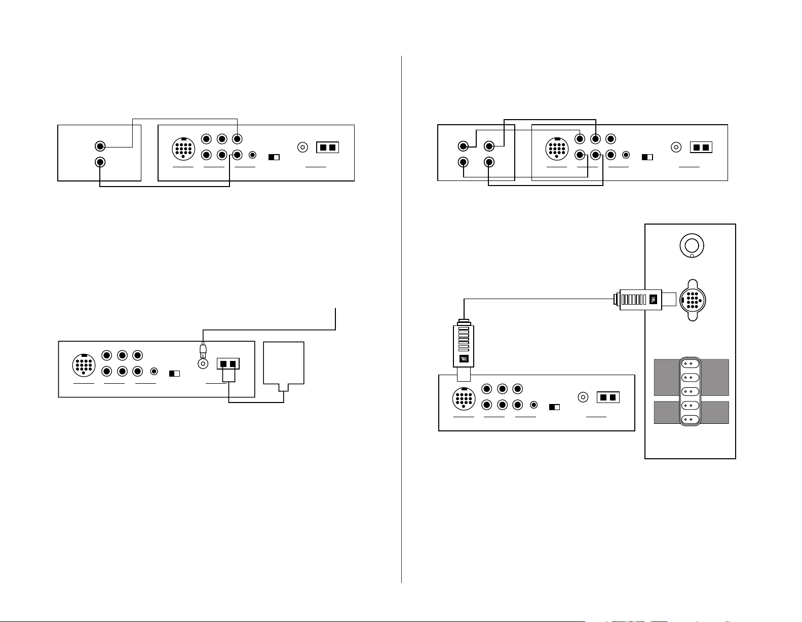
Connect TV or VCR to The Source
Note: The Source also
provides a stereo mini-jack (B)
to provide an easy connection
to devices that have a stereo
mini-jack audio output.
Connect Antennas to The Source
Connect Optional Cassette Deck to The Source
Connect The Source to a Subwoofer
– 6 –
Page 4
Left Front
Center
Right Front
OUTPUTS
Right Surround
Left Surround
FRONT
SPEAKERS
SURROUND
SPEAKERS
RIGHT
CENTER
LEFT
RIGHT
LEFT
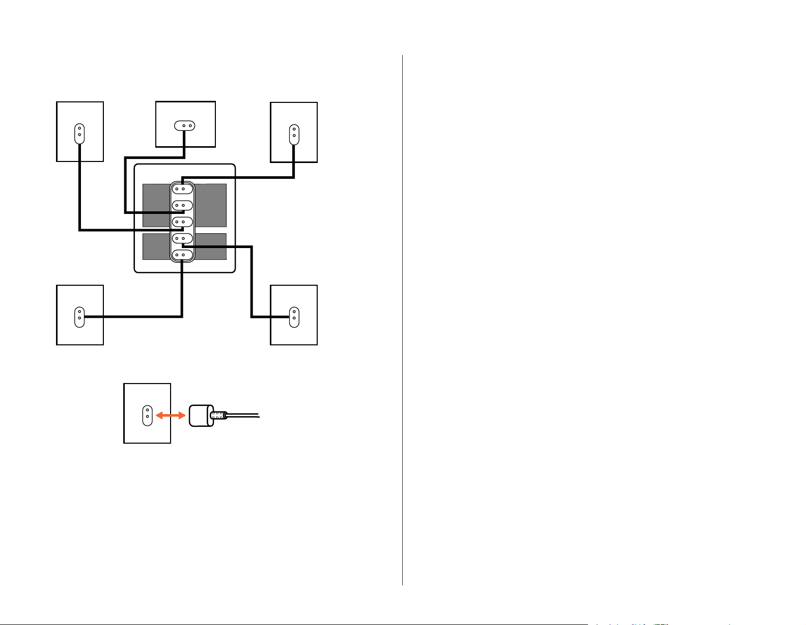
Speaker and Amplifier Connection
Speaker Connections
3
– 7 –
Page 5
Operation
Mute
Volume
+–
Volume
Mute
Volume
+–
Volume
Mute
+–
Volume
CD
Open
Random
Power
Volume
Skip
Search
Tune
Stereo/Mono
– Bass +
Surround Mode
– Treble + Tuner Presets
Auto Add
Tape/Aux
TV Auto Tune
AM/FM Repeat
Delete
Rear
Speakers
TM
Mute
Volume
CD
AM/FM
TV
Aux
Surround
Tone
Calibrate
Power Sleep
+–
+–
The Source
Remote Control
4
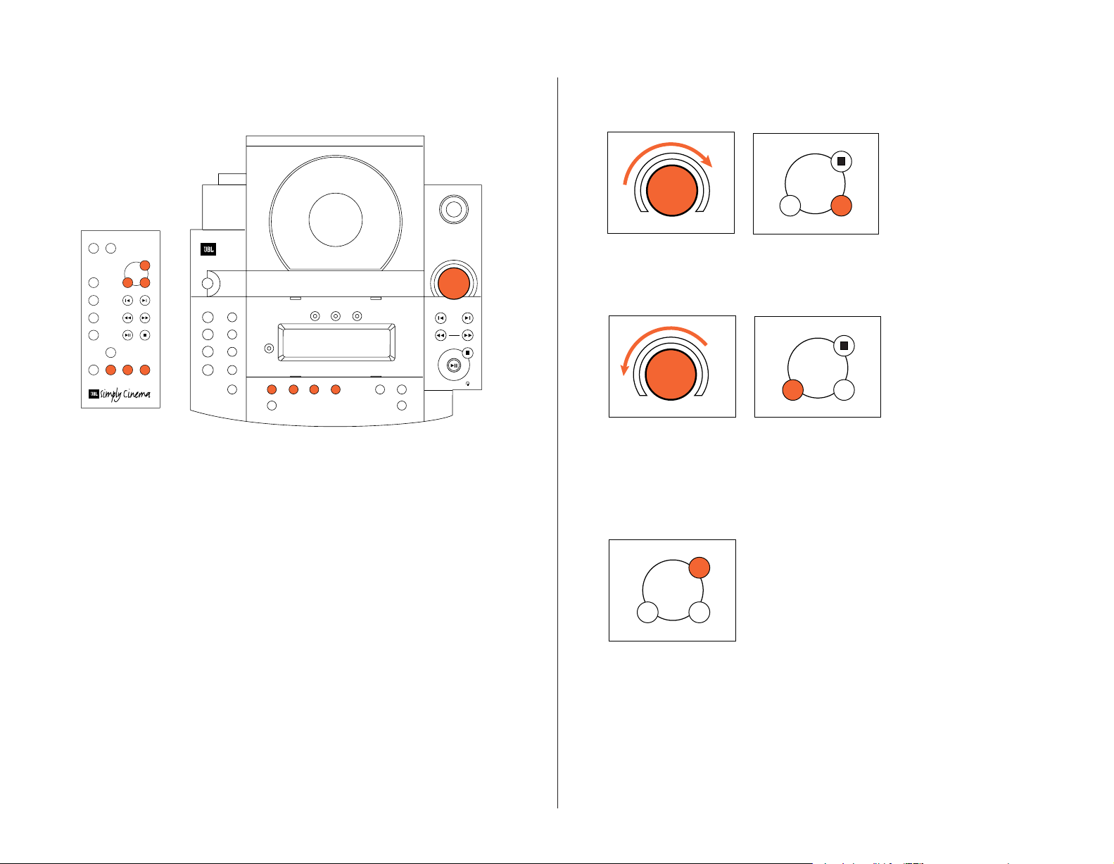
Volume
THE SOURCE
To raise volume:
Turn control on The Source
REMOTE
push “+” on the remote
control.
clockwise or
THE SOURCE
To lower volume:
Turn volume control
REMOTE
push “–” on the remote
control.
on The Source counterclockwise or
Mute
REMOTE
– 8 –
To lower volume
completely: Push “Mute”
on the remote control.
When “Mute” is pushed
again, the volume will
return to its original level.
Page 6
+
– Treble +
+
– Treble +
Surround
Calibrate
+–
Surround
Calibrate
+–
Bass
– Bass +
Surround Mode
– Treble
– Bass +
Surround Mode
– Treble
Surround
Calibrate
+–
Surround
Calibrate
+–
5
Treble
THE SOURCE
To raise the bass level:
Push “+” on The Source or
THE SOURCE
To lower the bass level:
Push “–” on The Source or
REMOTE
push “Calibrate” on the
remote control until “Bass”
illuminates in The Source
display. Push “+” until you
reach the desired level.
REMOTE
push “Calibrate” on the
remote control until “Bass”
illuminates in The Source
display. Push “–” until you
reach the desired level.
THE SOURCE
To raise the treble level:
Push “+” on The Source or
THE SOURCE
To lower the treble level:
Push “–” on The Source or
REMOTE
push “Calibrate” on the
remote control until “Treble”
illuminates in The Source
display. Push “+” until you
reach the desired level.
REMOTE
push “Calibrate” on the
remote control until “Treble”
illuminates in The Source
display. Push “–” until you
reach the desired level.
– 9 –
Page 7
AM/FM
TV
Aux
Skip
Search
Tune
CD Operation
Open
Power
Volume
Search
Tune
AM/FM
TV
Aux
TV
Aux
Surround
Skip
Search
Tune
CD
Open
Random
Power
Volume
Skip
Search
Tune
Stereo/Mono
– Bass +
Surround Mode
– Treble + Tuner Presets
Auto Add
Tape/Aux
TV Auto Tune
AM/FM Repeat
Delete
Rear
Speakers
TM
Mute
Volume
CD
AM/FM
TV
Aux
Surround
Tone
Calibrate
Power Sleep
+–
+–
The Source
Remote Control
6
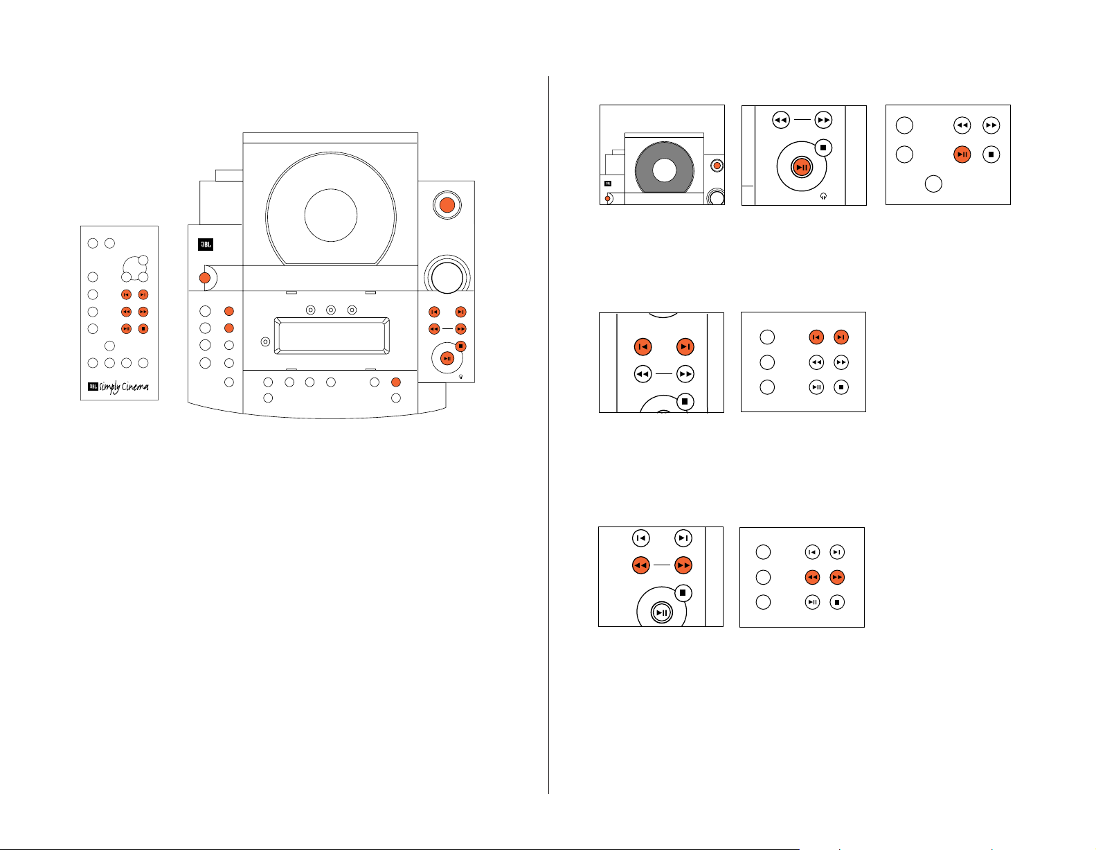
To Play a CD
THE SOURCE
1. Push “Power” and/or
“Open” on The Source.
2. Insert CD.
THE SOURCE
3. Push “Play” on The
Source or
REMOTE
the remote control.
(The door will close
automatically.)
To Skip to a Different Track
THE SOURCE
Push “|<” or “>|” on
The Source or
REMOTE
the remote control until the
number of the desired track
appears on the display.
To Scan within the Same Track
THE SOURCE
– 10 –
Push “<<” or “>>” on
The Source or
REMOTE
the remote control.
Page 8
Open
Power
Volume
Skip
Search
Tune
Tuner Presets
Auto Add
Delete
TV
Aux
Surround
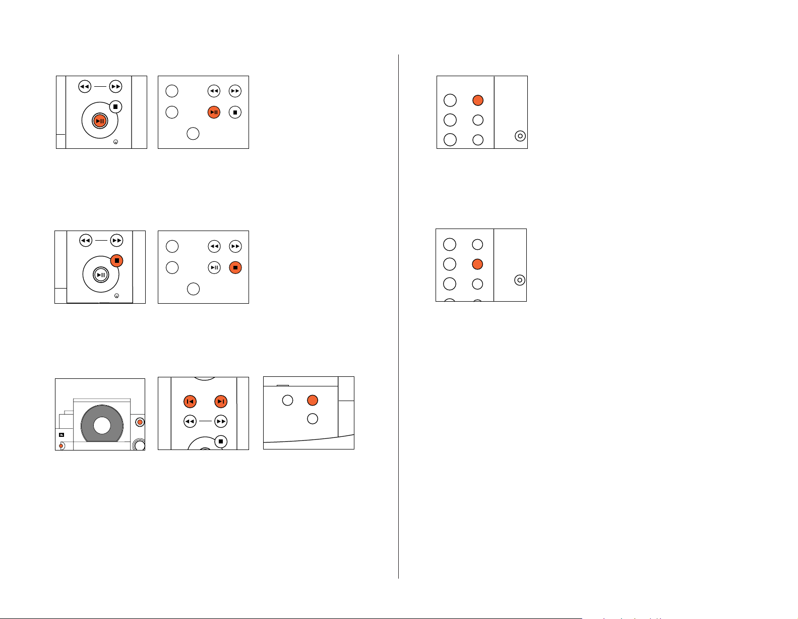
To Pause the CD
Search
Tune
Search
Tune
TV
Aux
Surround
CD Random
TV Auto Tune
AM/FM Repeat
CD Random
Stereo/MonoTape/Aux
TV Auto Tune
AM/FM Repeat
7
To Play the Tracks of a CD in Random Order
Push “Random” on The Source.
The Source will automatically
delete each track it has played
from the “Random” operation.
THE SOURCE
Push “Pause” on The Source
or
To Stop the CD
THE SOURCE
Push “Stop” on The Source
or
To Program the CD
REMOTE
the remote control. Push
again to resume play.
REMOTE
the remote control.
THE SOURCE
To Repeat the Disc
Note: If “Random” and
“Repeat” are both engaged the
CD player will randomly play
the disc, deleting all played
tracks, until the disc is
finished. It will then randomly
play the disc again.
THE SOURCE
Push “Repeat” on The Source.
THE SOURCE
1. Push “Power” and/or
“Open” on The Source.
2. Insert CD.
THE SOURCE
3. Push “|<” or “>|” to
select desired track.
THE SOURCE
4. Push “Add” to program
track. Repeat procedure
until all desired tracks are
programmed.
– 11 –
Page 9

Tuner Operation
Power
Stereo/MonoTape/Aux
TV Auto Tune
AM/FM Repeat
Rear
Stereo/MonoTape/Aux
TV Auto Tune
AM/FM Repeat
Rear
AM/FM
TV
Aux
Mute
Volume
CD
AM/FM
Power Sleep
+
Mute
Volume
CD
AM/FM
Power Sleep
+
Skip
Search
Tune
CD
Open
Random
Power
Volume
Skip
Search
Tune
Stereo/Mono
– Bass +
Surround Mode
– Treble + Tuner Presets
Auto Add
Tape/Aux
TV Auto Tune
AM/FM Repeat
Delete
Rear
Speakers
TM
Mute
Volume
CD
AM/FM
TV
Aux
Surround
Tone
Calibrate
Power Sleep
+–
+–
The Source
Remote Control
8
To Switch Between AM and FM
THE SOURCE
Push “Power” on The Source
or
THE SOURCE
“AM/FM” on The Source or
REMOTE
the remote control.
– 12 –
THE SOURCE
Push “AM/FM” on
REMOTE
the remote control.
The Source or
To Tune to a Particular Station
THE SOURCE
Push “<<” or “>>” on
The Source or
REMOTE
the remote control. To
search rapidly, hold down
the “<<” or “>>” button.
Page 10

If a Selected FM Station is a Little Noisy
Stereo/MonoTape/Aux
TV Auto Tune
Rear
Speakers
AM/FM
TV
Aux
Stereo/MonoTape/Aux
TV Auto Tune
AM/FM Repeat
Rear
Speakers
Skip
Search
Tune
Skip
Search
Tune
AM/FM
TV
Aux
9
To Have the Tuner Search for the Next Strong Station
THE SOURCE
Push “Stereo/Mono” on The
Source. This will play the
selected station without
any stereo separation,
but there will be much
less background noise.
THE SOURCE
When in the “Mono” mode,
the “<<” or “>>” on The
Source or
REMOTE
the remote control will
tune up or down one
frequency at a time.
THE SOURCE
Push “Auto Tune” on
The Source.
THE SOURCE
Then, when you push “<<”
or “>>” on The Source or
REMOTE
the remote control, the
tuner will automatically
advance to the next
station with a strong
signal.
– 13 –
Page 11

Preset Operation
Tuner Presets
Auto Add
Delete
Skip
Search
Tune
Tuner Presets
Auto Add
Delete
Tuner Presets
Auto Add
Delete
AM/FM
TV
Aux
CD
Open
Random
Power
Volume
Skip
Search
Tune
Stereo/Mono
– Bass +
Surround Mode
– Treble + Tuner Presets
Auto Add
Tape/Aux
TV Auto Tune
AM/FM Repeat
Delete
Rear
Speakers
TM
Mute
Volume
CD
AM/FM
TV
Aux
Surround
Tone
Calibrate
Power Sleep
+–
+–
The Source
Remote Control
10
THE SOURCE
1. Tune to the station
that you want to add
into memory.
2. Push “Add” on The
Source. That station is now
THE SOURCE
3. To delete a preset:
Push “Delete” on The Source.
That station is now removed
from your selection of
stations in memory.
added to your selection of
stations in memory.
THE SOURCE
4. To skip between preset
REMOTE
the remote control.
stations: Push “|<” or “>|”
on The Source or
The Source has a unique
feature that will automatically place up to 32
stations in memory. To
activate this feature, push
and hold the “Auto” button
for one second. The tuner
will search the dial and
place the stations with a
THE SOURCE
Note: Activating this feature
will delete all stations that
were previously stored in
memory. To prevent this from
accidentally occurring, the
Auto button will only activate
if held for a full second.
strong signal into memory.
– 14 –
Page 12

– Bass +
Surround Mode
Rear
Speakers
Stereo/MonoTape/Aux
Rear
Speakers
Aux
Surround
Tone
Calibrate
+–
Surround Mode Operation
CD
Open
Random
Power
Volume
Skip
Search
Tune
Stereo/Mono
– Bass +
Surround Mode
– Treble + Tuner Presets
Auto Add
Tape/Aux
TV Auto Tune
AM/FM Repeat
Delete
Rear
Speakers
TM
Mute
Volume
CD
AM/FM
TV
Aux
Surround
Tone
Calibrate
Power Sleep
+–
+–
The Source
Remote Control
11
What is Dolby*Pro Logic*?
Dolby*Pro Logic*is an
encode/decode process by
which four channels of
sound-track information
are encoded into two
channels for playback on
VCRs, laser disc players,
and some TV broadcasts,
and then decoded back
into four channels for
playback through five
loudspeakers. Remember
that a Dolby Pro Logic
system consists of three
channels of information
for front left, center, and
right speakers and one
channel of mono surround
This system contains three surround modes.
1. Dolby Pro Logic –
In this mode all five
speakers are used.
2.
Dolby Pro Logic Phantom –
In this mode the center
channel does not operate.
This may be preferred
when listening to a music
source that was not
recorded with surroundchannel information.
information. The surround
channel is played back
through two speakers.
Dolby Pro Logic helps to
re-create all of the impact
and excitement of a movie
theater in your home.
3. 2-channel – In this
mode the program is
played back in a traditional stereo form.
THE SOURCE
To switch between the
three surround modes:
REMOTE
the remote control.
Push “Surround Mode” on
– 15 –
The Source or
THE SOURCE
If you are listening to a
program in the Dolby Pro
Logic Normal or Phantom
mode and you wish to turn
off the surround speakers:
Push “Rear Speakers” on
The Source.
Page 13

Test Tone
Surround
Calibrate
+–
Surround
Calibrate
+–
Surround
Calibrate
+–
Surround
Calibrate
+–
Surround
Calibrate
+–
Surround
Calibrate
+–
Aux
Surround
Tone
Calibrate
+–
CD
Open
Random
Power
Volume
Skip
Search
Tune
Stereo/Mono
– Bass +
Surround Mode
– Treble + Tuner Presets
Auto Add
Tape/Aux
TV Auto Tune
AM/FM Repeat
Delete
Rear
Speakers
TM
Mute
Volume
CD
AM/FM
TV
Aux
Surround
Tone
Calibrate
Power Sleep
+–
+–
The Source
Remote Control
Surround
Calibrate
+–
Surround
Calibrate
+–
Surround
Calibrate
+–
12
Balance
THE SOURCE
Using the remote control,
push “Tone.” Then adjust
the Center and Surround
levels until the volume
of all the speakers is the
same during the test.
Note: The test tone is
For proper Dolby Pro Logic
operation, a test tone
is used to calibrate the
volume settings of the
speakers. A noise will be
used to calibrate the
performance of the system.
When listening to an actual
recording, the volume level
of the surround channels is
generally much lower than
that of the front channels.
heard cycling, in order,
from the front left, center,
right, and both surround
speakers.
In fact, when listening to a
movie, virtually all of the
dialogue and a substantial
number of the effects are
reproduced through the
center channel.
– 16 –
REMOTE
Push “Calibrate” on the
remote control until
“Balance” appears in the
display.
Center-Channel Volume
REMOTE
Push “Calibrate” on the
remote control until “Center”
appears in the display and
the corresponding LED on
top of the display is lit.
Rear-Channel Volume
REMOTE
Push “Calibrate” on the
remote control until “Rear”
appears in the display and
the corresponding LED on
top of the display is lit.
REMOTE
Push “+” on the remote
control to adjust the balance
toward the right speaker.
REMOTE
Push “+” on the remote
control to increase the
volume of the center
channel.
REMOTE
Push “+” on the remote
control to increase
the volume of the rear
channels.
REMOTE
Push “–” on the remote
control to adjust the
balance toward the left
speaker.
REMOTE
Push “–” on the remote
control to decrease the
volume of the center channel.
REMOTE
Push “–” on the remote
control to decrease the
volume of the rear channels.
Page 14

Delay Time
0 5 10 15 20 25 30 35 40
40
35
30
25
20
15
10
5
0
15ms
15ms
15ms
20ms
25ms
30ms
30ms
30ms
Distance (in feet) From Front Speakers
Distance (in feet) from Rear Speakers
Preferable Acceptable
Surround
Calibrate
+–
Surround
Calibrate
+–
Surround
Calibrate
+–
CD
Open
Random
Power
Volume
Skip
Search
Tune
Stereo/Mono
– Bass +
Surround Mode
– Treble + Tuner Presets
Auto Add
Tape/Aux
TV Auto Tune
AM/FM Repeat
Delete
Rear
Speakers
TM
Mute
Volume
CD
AM/FM
TV
Aux
Surround
Tone
Calibrate
Power Sleep
+–
+–
The Source
Remote Control
13
The delay control allows
the user to set the surround delay between 15
and 30 milliseconds in
one-millisecond increments.
The best setting will
depend on the distance
between the main
listening area and the
front speakers as well as
the distance between the
main listening area and
the rear speakers. The chart
at the bottom shows the
recommended settings.
– 17 –
REMOTE
Push “Calibrate” on the
remote control until “Delay”
appears in the display and
the corresponding LED on
top of the display is lit.
REMOTE
Push “+” on the remote
control to increase the
delay time.
REMOTE
Push “–” on the remote
control to decrease the
delay time.
Page 15

Troubleshooting
14
If there is no sound from any
of the speakers, check the
following:
• Make sure the subwoofer is
plugged into an active AC wall
outlet.
• Make sure the Master Power
Switch, located on the rear of the
subwoofer, is in the “On/Standby”
position.
• Make sure there is a source –
for example, a VCR or television –
hooked up to the TV or tape/aux
input jacks on The Source.
• Make sure that the program
material is playing.
• Recheck the hookup connections.
If most of the sound comes from
the center-channel speaker, with
little or no information from
the surround channels, note the
following:
Although most of today’s televisions are equipped with stereo
audio output jacks, some stereo
televisions have poor audio sections and are unable to provide a
Dolby Pro Logic encoded signal. In
the unlikely event that you experi-
ence this problem, connecting the
audio outputs from your hi-fi VCR,
laser disc player, DVD player, or
satellite receiver directly to one of
the inputs on The Source will provide a proper audio signal and
allow you to enjoy true Dolby Pro
Logic surround sound.
If there is no sound from the
surround speakers or sound is
very low, check the following:
• Check all connections between
the amplifier and each of the
speakers.
• Raise the surround volume
from the remote control
(see “Operation” section).
• Make sure the TV show or movie
you are watching is recorded in
Dolby Surround.
If there is no sound from the
center speaker, check the
following:
• Make sure that the processor
is in the Pro Logic mode. If it is
in Phantom or Stereo mode, the
center speaker will not play.
• Check the connections between
the subwoofer and the center
speaker.
If you have low bass output,
check the following:
• Experiment with placement of
the subwoofer. Remember, place
the subwoofer in a corner to get
maximum bass output from the
system.
• Increase the level of bass,
using the remote control.
• Adjust the level control on the
rear of the subwoofer.
If you are having trouble picking
up radio stations, check the
following:
• Make sure the antenna is
hooked up properly.
• Depending on your distance from
the station’s transmitter, you may
need to install an FM antenna on
the roof or in the attic.
– 18 –
Page 16

SUB350 exploded view
15
Page 17

SUB350 ELECTRICAL PARTS LIST
Part#
Description
Qty
Designator/Details
16
Semiconductors
RAN0945-001 XISTR NPN 2SC945P NEC 1
RHI0740-001 IC 14 PIN TL074CN DUAL OP. AMP IC 5
RHI1237-001 IC 8 PIN UPC1237HA NEC PROTECT IC 1
RHI1298-001 IC 14 PIN uPC1298V NEC 50-80W POWER AMP DRV
RHI4558-001 IC 8 PIN JRC4558D JRC DUAL OP. AMP IC 1
RHI7809-001 IC 3 PIN 7809 9V 1A REGULATOR 1
RHI7812-001 IC 3 PIN 7812 12V 1A REGULATOR 1
RHI7912-001 IC 3 PIN 7912 REGULATOR 1
RHI7915-001 IC 3 PIN 7915 REGULATOR 1
RHN0882-001 XISTR NPN 2SD882P 1
RHP0772-001 XISTR PNP 2SB772P/Q NEC 1
RAP0733-001 XISTR PNP 2SA733Q,P NEC 1
RHN5198-001 XISTR NPN 2SC5198-O TOSHIBA HFE:80-160 W/MICA
RHP1941-001 XISTR PNP 2SA1941-O TOSHIBA HFE:80-160 W/MICA
RAD4148-001 DIODE SW 1N4148 1
RAN0945-001 XISTR NPN 2SC945P NEC 4
RAP0733-001 XISTR PNP 2SA733Q,P NEC 1
RAD4001-001 RECTIFIER 1N4001 1A 35VRMS 8
RAD4148-001 DIODE SW 1N4148 1
RAZ4747-001 DIODE ZENR 19.5-20.4V 1W 1N4747 ZENER 4 IC501 PIN 4 TO GND, IC501 PIN 12 TO GND,
RHD5401-001 RECTIFIER 1N5401 3A 70VRMS
RHI4151-001 IC 18 PIN STK4151MK5 SANYO 2CH 30W POWER AMP
RHI7815-001 IC 3 PIN 7815 15V 1A REGULATOR
RAD4001-001 RECTIFIER 1N4001 1A 35VRMS
RAD4148-001 DIODE SW 1N4148
RAN0945-001 XISTR NPN 2SC945P NEC
RAN2001-001 XISTR NPN 2SC2001L NEC
RAD4001-001 RECTIFIER 1N4001 1A 35VRMS
RAN0945-001 XISTR NPN 2SC945P NEC
RAN2001-001 XISTR NPN 2SC2001L NEC
RAP0733-001 XISTR PNP 2SA733Q,P NEC
RHD5401-001 RECTIFIER 1N5401 3A 70VRMS
"B" AND "C" TO IC852 PIN 6 "E" TO GND
IC405 IC406 IC753 IC754 IC851
IC701
1
IC802
IC852
IC904
IC905
IC906
IC907
Q803, Q914
Q910
Q601
1
Q801
1
Q802
D919
Q909 Q911 Q912 Q915
Q913
D901 D902 D911 D912 D913 D914 D916 D917
D601
IC502 PIN 4 TO GND, IC502 PIN 12 TO GND
4
D907 D908 D909 D910
2
IC501 IC502
1
IC901
1
D801
4
D802 D803 D804 D806
2
Q804 Q806
1
Q805
5
D501 D903 D904 D905 D906
1
Q908
1
Q511
1
Q505
4
D810 D811 D812 D813
Capacitors
Page 18

Part#
Description
Qty
Designator/Details
PRD1335-100 COND DISC 10 pF 50V 5% NP0
17
PRD3545-102 COND DISC 1000 pF 50V 10% Y5P
PRD3545-221 COND DISC 220 pF 50V 10% Y5P II D=5
PRD3965-104 COND DISC 0.1 uF 50V +80-20% Y5V/Z5V
PRD4967-223 COND DISC .022 uF 100V +80-20% Z5V II D=7
PRE3951-100 COND ELECT 10 uF 10V 20% 85'C
PRE3952-100 COND ELECT 10 uF 16V 20% 85'C
PRE3954-101 COND ELECT 100 uF 35V 20% 85'C
PRE3955-100 COND ELECT 10 uF 50V 20% 85'C
PRE3955-101 COND ELECT 100 uF 50V 20% 85'C
PRE3955-109 COND ELECT 1 uF 50V 20% 85'C
PRE3955-470 COND ELECT 47 uF 50V 20% 85'C
PRM3745-104 COND MYLAR 0.1 uF 50V 10%
PVD1395-100 COND DISC 10 pF 50V +-0.5pF NP0 HI PITCH=5 mm
PVE3954-222 COND ELECT 2200 uF 35V 20% P=5/7.5 mm
PVE3955-332 COND ELECT 3300 uF 50V 20%
PVE3953-222 COND ELECT 2200 uF 25V 20% 1
PRD3545-101 COND DISC 100 pF 50V 10% Y5P 4
PRD3545-104 COND DISC 0.1 uF 50V 10% Y5P 21
PRD3545-201 COND DISC 200 pF 50V 10% Y5P 4
PRD3545-681 COND DISC 680 pF 50V 10% Y5P 4
PRD4965-203 COND DISC 0.02 uF 50V +80-20% Z5V II D=7 4
PRE3951-100 COND ELECT 10 uF 10V 20% 85'C 1
PRE3951-221 COND ELECT 220 uF 10V 20% 85'C 1
PRE3952-220 COND ELECT 22 uF 16V 20% 85'C 1
PRE3952-221 COND ELECT 220 uF 16V 20% 85'C 5
PRE3955-109 COND ELECT 1 uF 50V 20% 85'C 8
PRE3955-229 COND ELECT 2.2 uF 50V 20% 85'C 1
PRE3955-479 COND ELECT 4.7 uF 50V 20% 85'C 4
PRM3737-102 COND MYLAR 0.001 uF 100V 5% 8
PRM3737-123 COND MYLAR 0.012 uF 100V 5% 1
PRM3737-182 COND MYLAR 0.0018uF 100V 5% 4
PRM3737-183 COND MYLAR 0.018 uF 100V 5% 2
PRM3737-273 COND MYLAR 0.027 uF 100V 5% 8
PRM3737-303 COND MYLAR 0.03 uF 100V 5% 1
PRM3737-392 COND MYLAR 0.0039uF 100V 5% 4
PRM3737-472 COND MYLAR 0.0047uF 100V 5% 8
PRM3737-683 COND MYLAR 0.068 uF 100V 5% 1
PRM3737-823 COND MYLAR 0.082 uF 100V 5% 2
PRN3952-100 COND ELECT 10 uF 16V 20% NON-POLAR 1
2
4
4
4
8
1
1
4
2
2
5
4
6
2
2
2
C518 C538
C501 C502 C521 C522
C515 C516 C535 C536
C921 C922 C923 C924
C903 C904 C905 C906 C907 C908 C909 C910
C541
C533
C505 C506 C525 C526
C512 C532
C511 C531
C503 C504 C523 C524 C534
C507 C508 C527 C528
C509 C510 C529 C530 C918 C920
C517 C537
C915 C916
C917 C919 C820 C821
C926
C485 C486 C735 C736
C473 C474 C475 C476 C721 C722 C723 C724 C852 C853
C865 C866 C928 C931 C935 C936 C937 C945 C946 C947
C948
C463 C464 C713 C714
C469 C470 C719 C720
C941 C942 C943 C944
C934
C949
C911
C932 C933 C938 C939 C940
C487 C488 C489 C490 C737 C738 C739 C851
C861
C857 C858 C859 C912
C457 C458 C459 C460 C707 C708 C709 C710
C806
C461 C462 C711 C712
C854 C855
C453 C454 C455 C456 C703 C704 C705 C706
C856
C451 C452 C701 C702
C465 C466 C467 C468 C715 C716 C717 C718
C805
C803 C804
C950
Page 19

Part#
Description
Qty
Designator/Details
PRD1335-150 COND DISC 15 pF 50V 5% NP0
R491 R492 R493 R494 R740 R741 R742 R743 R853 R854
R461 R462 R463 R464 R711 R712 R713 R714 R856 R858
18
PRD3545-101 COND DISC 100 pF 50V 10% Y5P
PRD3545-102 COND DISC 1000 pF 50V 10% Y5P
PRD3965-104 COND DISC 0.1 uF 50V +80-20% Y5V/Z5V
PRE3951-101 COND ELECT 100 uF 10V 20% 85'C
PRE3955-229 COND ELECT 2.2 uF 50V 20% 85'C
PRM3737-104 COND MYLAR 0.1 uF 100V 5%
PRM3737-123 COND MYLAR 0.012 uF 100V 5%
PRM3737-393 COND MYLAR 0.039 uF 100V 5%
PRM3737-473 COND MYLAR 0.047 uF 100V 5%
PRM3737-563 COND MYLAR 0.056 uF 100V 5%
PRM3737-683 COND MYLAR 0.068 uF 100V 5%
PRM3745-104 COND MYLAR 0.1 uF 50V 10%
Resistors
1
C809
1
C814
1
C810
2
C801 C802
1
C813
1
C808
2
C803 C804
1
C806
1
C812
4
C830 C831 C832 C833
1
C807
2
C805 C811
2
C822 C823
QAF0620-351 RESISTOR 350 OHM 1/6W 2% CF 1
QAF0650-103 RESISTOR 10K OHM 1/6W 5% CF 2
QAF0650-104 RESISTOR 100K OHM 1/6W 5% CF 1
QAF0650-152 RESISTOR 1.5K OHM 1/6W 5% CF 1
QAF0650-474 RESISTOR 470K OHM 1/6W 5% CF 1
QAF0650-822 RESISTOR 8.2K OHM 1/6W 5% CF 1
QAF0250-102 RESISTOR 1.0K OHM 1/2W 5% CF 1
QAF0450-822 RESISTOR 8.2K OHM 1/4W 5% CF 1
QAF0650-101 RESISTOR 100 OHM 1/6W 5% CF 12
QAF0650-102 RESISTOR 1K OHM 1/6W 5% CF 1 R861
QAF0650-103 RESISTOR 10K OHM 1/6W 5% CF 32
QAF0650-104 RESISTOR 100K OHM 1/6W 5% CF 9 R469 R470 R483 R484 R719 R720 R733 R734 R915
QAF0650-123 RESISTOR 12K OHM 1/6W 5% CF 1 R911
QAF0650-152 RESISTOR 1.5K OHM 1/6W 5% CF 1 R920
QAF0650-153 RESISTOR 15K OHM 1/6W 5% CF 11
QAF0650-183 RESISTOR 18K OHM 1/6W 5% CF 1
QAF0650-184 RESISTOR 180K OHM 1/6W 5% CF 1
QAF0650-202 RESISTOR 2K OHM 1/6W 5% CF 8
QAF0650-223 RESISTOR 22K OHM 1/6W 5% CF 1
QAF0650-243 RESISTOR 24K OHM 1/6W 5% CF 4
QAF0650-334 RESISTOR 330K OHM 1/6W 5% CF 3
FROM C485 (-) TO IC852 PIN5
Q915 BETWEEN "B" TO "E", FR.IC852 PIN 8 TO PIN 6
FROM Q909 "BASS" TO IC852 PIN 7
Q913 BETWEEN "B" TO "E"
FR. IC852 PIN 7 TO PIN 5
FROM IC852 PIN 8 TO PIN 5
R910
R917
R869 R870
R451 R452 R453 R454 R459 R460 R467 R468 R485 R486
R703 R704 R709 R710 R715 R716 R735 R736 R753 R754
R863 R864 R909 R916 R918 R919 R921 R922 R923 R925
R926 R927
R929
R801
R802
R455 R456 R481 R482 R705 R706 R731 R732
R803
R473 R474 R723 R724
R489 R490 R739
Page 20

Part#
Description
Qty
Designator/Details
QAF0650-363 RESISTOR 36K OHM 1/6W 5% CF 1
19
QAF0650-392 RESISTOR 3.9K OHM 1/6W 5% CF 1
QAF0650-394 RESISTOR 390K OHM 1/6W 5% CF 1
QAF0650-472 RESISTOR 4.7K OHM 1/6W 5% CF 9
QAF0650-473 RESISTOR 47K OHM 1/6W 5% CF 2
QAF0650-563 RESISTOR 56K OHM 1/6W 5% CF 2
QAF0650-682 RESISTOR 6.8K OHM 1/6W 5% CF 2
QAF0650-683 RESISTOR 68K OHM 1/6W 5% CF 1
QAF0650-913 RESISTOR 91K OHM 1/6W 5% CF 8
QAF0450-681 RESISTOR 680 OHM 1/4W 5% CF 1
QAF0650-102 RESISTOR 1K OHM 1/6W 5% CF 2
QAF0650-223 RESISTOR 22K OHM 1/6W 5% CF 1
QAS0200-475 RESISTOR 4.7M OHM 1/2W 10% UL STATIC DISCHARGE 1
QAF0250-100 RESISTOR 10 OHM 1/2W 5% CF
QAF0250-101 RESISTOR 100 OHM 1/2W 5% CF
QAF0650-102 RESISTOR 1K OHM 1/6W 5% CF
QAF0650-153 RESISTOR 15K OHM 1/6W 5% CF
QAF0650-154 RESISTOR 150K OHM 1/6W 5% CF
QAF0650-204 RESISTOR 200K OHM 1/6W 5% CF
QAF0650-223 RESISTOR 22K OHM 1/6W 5% CF
QAF0650-392 RESISTOR 3.9K OHM 1/6W 5% CF
QAF0650-393 RESISTOR 39K OHM 1/6W 5% CF
QAF0650-472 RESISTOR 4.7K OHM 1/6W 5% CF
QAF0650-473 RESISTOR 47K OHM 1/6W 5% CF
QAF0650-563 RESISTOR 56K OHM 1/6W 5% CF
QAF0650-683 RESISTOR 68K OHM 1/6W 5% CF
QAF0250-331 RESISTOR 330 OHM 1/2W 5% CF
QAM0250-479 RESISTOR 4.7 OHM 1/2W 5% MF
QHM1050-479 RESISTOR 4.7 OHM 1W 5% MF HI P:15mm W/KINK
QVE3050-228 RESISTOR 0.22 OHM 3W 5% HI CEMENT FIXED RADIAL
QAF0650-202 RESISTOR 2K OHM 1/6W 5% CF
QAM0250-479 RESISTOR 4.7 OHM 1/2W 5% MF
QHS0250-100 RESISTOR 10 OHM 1/2W 5% FUSEABLE
QVE3050-228 RESISTOR 0.22 OHM 3W 5% HI CEMENT FIXED RADIAL
QAF0450-102 RESISTOR 1.0K OHM 1/4W 5% CF
QAF0450-222 RESISTOR 2.2K OHM 1/4W 5% CF
QAF0650-102 RESISTOR 1K OHM 1/6W 5% CF
QAF0650-103 RESISTOR 10K OHM 1/6W 5% CF
QAF0650-152 RESISTOR 1.5K OHM 1/6W 5% CF
QAF0650-154 RESISTOR 150K OHM 1/6W 5% CF
QAF0650-223 RESISTOR 22K OHM 1/6W 5% CF
R804
R860
R852
R479 R480 R487 R488 R729 R730 R737 R738 R859
R865 R924
R913 R914
R855 R857
R862
R457 R458 R471 R472 R707 R708 R721 R722
R601
R603 R604
R602
AC LINE CORD TO SOLDER LUG
1
R815
1
R817
2
R808 R820
2
R806 R807
1
R825
1
R802
1
R824
1
R809
1
R821
1
R805
1
R818
1
R810
1
R822
4
R515 R518 R535 R538
4
R511 R512 R531 R532
1
R928
4
R545 R546 R547 R548
1
VR801
1
R816
2
R811 R812
2
R813 R814
4
R516 R517 R536 R537
8
R507 R508 R509 R510 R527 R528 R529 R530
9
R503 R504 R505 R506 R523 R524 R525 R526 R562
3
R564 R907 R908
1
R902
4
R549 R550 R551 R552
2
R565 R570
Page 21

Part#
Description
Qty
Designator/Details
QAF0650-472 RESISTOR 4.7K OHM 1/6W 5% CF
HSINK TO WOOD BOX-10, JACK PLT TO WOOD BOX-8, MAIN
20
QAF0650-473 RESISTOR 47K OHM 1/6W 5% CF
MRR0503-012 CNTL ROTRY 50K OHM B DOUBLE T-MCRV162G L=15W/NET 1
Miscellaneous
TTK1200-008 PWR TRANS EI-96 120V ESC350 (JBL) 1 POWER TRANSFORMER (120v)
FTW6080-312 SPK DRIVER 60W 8" 4 OHM 1
IVE0041-001 WFR GASKET OD210xID184xT1.0 mm EVA BLK W/ADHESIVE 1
KSA2200-002 FUSE 2A 250V SLOW 5x20mm VDE 1
KSA2100-002 FUSE 1A 250V SLOW 5x20mm UL/CSA/T-MARK 1
KSA2315-104 FUSE 3.15A 250V SLOW 5x20mm RUL/VDE 1
KSA1600-101 FUSE 6A 125V SLOW 5x20mm UL/CSA/T-MARK 1
MRL2212-002 RELAY MI-SH-212LM 12V DC 44 mA GOOD SKY 2
MRL2212-005 RELAY SHINMEI RPA-12 V DC 10A(AC)250V
MSV0001-004 SW ROCKER 5A AC 250V TV-5 CHILY CAT NO.3051
2559-080022 LINE LINK 370 mm BLACK VDE 1
47455-D52 LINE CORD SPT-2 1980mm POLARIZ BLK-UL DBL INSULA 1
GTN0043-002 TIN FOIL L280xW180xT0.5mm ESC300b/ESC350 1
H016504-316 SCREW W6#-20xL16 mm BLACK WAFER HEAD 4
H016701-316 SCREW W8#-18xL16 mm HD=6.8 BLACK PAN HEAD 8
H060501-320 SCREW M4.0xP0.7xL20 mm BLACK PAN HEAD 22
CCN3962-006 CONNECTOR 6 PIN CL3962WVO POST BASE TOP P=3.96 1
CCN3962-008 CONNECTOR 8 PIN CL3962WVO POST BASE TOP P=3.96 1
CFC2557-001 FUSE CLIP DIA5xL20mm FUSE 4
DFH1229-001 FUSE HOLDR FUSE HOLDER FH-B02 10A; DIA 5.2x20
GAL0010-005 HEAT SINK 1
H100301-306 SCREW M3.0xL6 mm BLACK 1
H120302-308 SCREW M3.0x0.5PxL8.0 mm BLK W/WASHER HEAD
HNI1482 NUT @14x3.5mm
HWF8335-005 WASHER FIB OD8.3xID3.5xT0.5 mm UNFINISHED
HWS1550-515 WASHER STL OD15xID5.0xT1.5mm ZINC PLATE
BPA0021-001 REAR COVER HI-PS ESC350 (JBL)
BRB0004-001 RUBBER BUS NR-3
BRB0005-001 RUBBER BUS NR-3
BRB0022-001 RUBBER
BRB0023-001 RUBBER
BRF0007-001 RUBBER BLACK
CCN0027-003 AC CONNTOR AC CONNECTOR (HW-C4) FOR WIRE #16-24
DBU0002-001 BUSHING AC LINE BUSHING PIN GOOD 4RF-5
GSE0139-004 JACK PLATE SECC 120V ESC350 (JBL)
1
R561
8
R501 R502 R513 R514 R521 R522 R533 R534
VR804
WOOFER
FOR DRIVER
F901
RL501 RL502
1
RL801
AC SW TO X'FORMER
MAIN PCB SHILDING
BOTTOM TO WOOD BOX-4
DRIVER TO WOOD BOX-8
PCB TO WOOD PCB-4
CN901
CN501
FOR F902 F903
FOR IC901
IC901 TO H/SINK-1
Page 22

Part#
Description
Qty
Designator/Details
H060301-314 SCREW M3.0xP0.5xL14 mm BLACK PAN HEAD
21
H101001-310 SCREW M3.0xP1.27-2RHxL10mm BLACK PAN HEAD
HNM3055-125 NUT M3.0x2.5t NICKEL
APE0247-A21 TEMINAL AY TERMINAL PCB ASSY ESC350 (JBL) (AI) 1
CJD0001-001 DIN JACK 13 PIN HOSIDEN TCS5003-01-4151 1
CSL6521-002 SOLDER LUG OD7.0xID3.5xT0.3 mm NICKEL 1
CTM0005-001 TERMINAL JACK ASSY MOLEX TYPE ABS BLK (ESC300) 1
DSS0545-003 HOUSING LED HOUSING LEK2-4.5 5 DIA H=4.5 mm 1
KEM0001-001 LED 5 DIA RED/GREEN TWO COLORS CHANGE 1
4999A-296 CON/WRE AY 8 COND 350 mm RECEPTACLE TERMINAL 1
4999A-461 CON/WRE AY 3 COND 200 mm P=2.5mm SHIELD WIRE 1
4999A-462 CON/WRE AY 8 COND 250 mm P=2.5mm SHIELD WIRE 1
APE0247-021 TERM PCB A TERMINAL PCB ASSY ESC350
CCN1500-018 CONNECTOR B2B-XH-A 2 PIN POST BASE TOP P=2.5 5
CCN1500-023 CONNECTOR B3B-XH-A 3 PIN POST BASE TOP P=2.5 1
CCN1500-024 CONNECTOR B6B-XH-A 6 PIN POST BASE TOP P=2.5 1
CCN1500-033 CONNECTOR B9B-XH-A 9 PIN POST BASE TOP P=2.5 1
CCN1500-037 CONNECTOR B8B-XH-A 8 PIN POST BASE TOP P=2.5 1
CCN3962-002 CONNECTOR 2 PIN CL3962WVO POST BASE TOP P=3.96 1
CFC2557-001 FUSE CLIP DIA5xL20mm FUSE 2
CFC2557-001 FUSE CLIP DIA5xL20mm FUSE
CSL6521-003 SOLDER LUG OD13.0xID9.0xT0.3 mm JG-30 1
DSS0011-001 SPACER SUP PINGOOD RL-1/6S 1SET ESC300 4
GAL0007-001 HEAT SINK USE MKH-610 2
GAL0010-005 HEAT SINK 2
H101012-206 SCREW T3.0x1.27p-2RHxL6.mm ST.BRONZE 4
500361001B0 COND WIRE 6 COND 100 mm P=2.5mm FLAT WIRE 1
SHR6619-001 RF COIL 1 uH MDEC T40818-08
SHR6619-001 RF COIL 1 uH MDEC T40818-08
24684150BB0 FLAT CABLE 4 COND 150 mm
5002EBE1BMM COND WIRE 2 COND 250 mm BROWN
5002EBJ2BMM COND WIRE 2 COND 200 mm GRAY
5002ECEABMM COND WIRE 2 COND 350 mm BLACK PITCH=2.5mm
5002ECJ4BMM COND WIRE 2 COND 300 mm WHITE PITCH=2.5mm
500361501B0 COND WIRE 6 COND 150 mm BLACK P:2.5mm UL2877 #26GA
500393001B0 COND WIRE 9 COND 300 mm BLACK 26 AWG PITCH=2.5 mm
CCN1500-024 CONNECTOR B6B-XH-A 6 PIN POST BASE TOP P=2.5
CCN3962-003 CONNECTOR 3 PIN CL3962WVO POST BASE TOP P=3.96
5002ABEBBMM CON/CABLE 2 COND 200 mm RED 1533 #28 PITCH:2.5mm
VWT13A3-025 WIRE TERM WIRE TERMINAL 250 mm +BIG TML -SMALL TML
JK401
P501
JK501
FOR LED501
LED501
RIB501 TO CN501
RB805
RB401
CN503 CN504 CN701 CN702 CN804
CN805
CN402
CN502
CN401
CN601
F901
4
F801 F802
P1
MAIN PCB
IC905, IC906
IC904 , IC907
IC904, IC905, IC906, IC907
RB402
4
L501 L502 L503 L504
1
L801
1
RB505A TO RB505B
1
RIB503 TO CN503
1
RIB504 TO CN504
1
RIB701 TO CN701
1
RIB702 TO CN702
1
RIB801 TO CN801
1
RIB502 TO CN502
1
CN801
1
CN803
1
RIB804 TO CN804
1
CN802 TO SPEAKER
Page 23

22
Page 24

23
Page 25

ESC350 PACKAGE
24
EAT3001-301L CENTER SPEAKER CABLES 3M BLK 1
EAT3001-301II FRONT SPEAKER CABLES 6M BLK 2
SAL054 REAR SPEAKER CABLE 12M BLK 2
FBL0030-001 BATTERY LITHIUM BATTERY 3V DIA=20, H=2.5 mm 1
ICC0160-001 OUTER CARTON 430Wx430Dx793H mm ESC350 1
VDC0013-001 CONTROL CABLE DIN TYPE 13 PIN 16 FT 1
WIR0020-432 REMOTE 20KEY REMOTE CONTROL 1
YOM0188-001 OWNER MANUAL ESC350 1
YWC0009-002 REGIS CARD REGISTRATION CARD JBL A9C01-01 120V 1
YWC0009-005 WARRANTY CARD 1Y ELEC & 5Y LOUDSPK WARRANTY CARD 120V 1
VTA9300-009 LOOP ANT SHINTA PS-100
VTA9300-012 F PLUG ANT FM PLUG L=1 M
1
1
 Loading...