

Page 1
Surround Cinema
SUB300
Amplifier/Subwoofer
SERVICE MANUAL
JBL Consumer Products
250 Crossways Park Dr.
Woodbury, New York 11797 Rev
2 10/2005
Page 2

1
Note: The SUB300 is part of the SCS300. 7 system
Satellite loudspeakers SCS300SAT: order JBL part# SCS300SAT-1
Center channel SCS300CEN: order JBL part# SCS200/300CEN-1
- CONTENTS -
BASIC SPECI FI C ATI ONS……………….….….….….…………….1
DETAILED SPECIFICATIONS ……..…………….……………..2
OPERATION ………….……………………………..…………….4
CONNECTIONS..………………………..………….…….………...5
BASIC TROUBLESHOOTING…..…………….….….…….……...7
TEST SET-UP AND PROCEDURE……………………………….8
EXPLODED VIEW/PARTS LIST…………………………………..9
BLOCK DIAGRAM..…………………………………………….....10
PCB DRAWINGS………………..………………………………...11
120V ELECTRICAL PARTS LIST ………………..……………..13
230V ELECTRICAL PARTS LIST …………………..…………..16
INTEGRATED CIRCUIT/TRANSISTOR PINOUTS.................19
120V SCHEMATICS.………..………………….………. ………20
230V SC H EMATICS.………..…………………….……. ………23
PACKAGING…………………………….………………………...25
BASIC SPECIFI C ATIONS
SUB300 Subwoofer
Configuration: Floor-firing, bass-reflex ported enclosure
Woofer: 10" (254mm) cone
Amplifier Power output: 150W Continuous RMS power
Frequency response: 30Hz – 120Hz (-6dB)
Dimensions (including feet): 20 x 13 ¾ x 15 ¾” (508 x 349 x 400mm)
Weight: 35 lb/15.9kg
Occasional r efinements may be made to existing produc ts without noti c e but will always meet or exceed original
specifications unl ess otherwise stated
Page 3
P
SUB300 (SCS300.7sys)
2
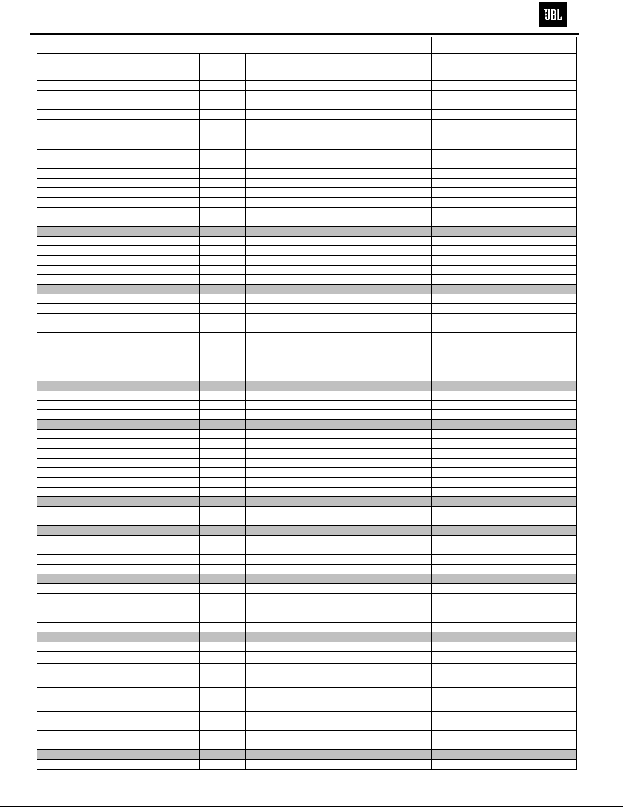
JBL SUB 300 150W Powered Sub/ Plate Amp
LINE VOLTAGE Yes/No Hi/Lo Line Unit Notes
Parameter Specification Unit
Amp Section
Type (Class AB, D, other) D D
Load Impedance (speaker) 4 Ohms
Rated Output Power 150 Watts
THD@ Rated Power 0.5 %
THD @ 1 Watt 0.1 %
DC Offset 10 mV-DC
Damping factor >100 DF
Input Sensitivity
Signal to Noise
SNR-A-Weighted 100 dBA
SNR-unweighted 90 dBr
SNR @ 1W-unweighted 60 dBr
Residual Noise Floor 1 mVrms
Residual Noise Floor 1
US 120VAC/60Hz Yes 108-132 Vrms
Asia 100VAC/50Hz Yes 90-110 Vrms
EU 230VAC/50-60Hz Yes 207-264 Vrms Normal Operation Normal operation, MOMS required
QA Test
Limits Conditions Notes
N/A
N/A Nominal
140 1 input driven
0.3 22KHz filter
Input Frequency 50 Hz
Line Input (L&R) 250 mVrms
LFE Input 145 mVrms
Speaker/Hi Level Input 2.5 Vrms
mVrms(max)
±2dB To rated power 1 input driven
±2dB To rated power LFE input driven only
±2dB To rated power (-20 dB below Line In)...1 input driven
Normal Operation
Normal Operation
1 22KHz filter
50 @ Speaker Outputs
30
50 Nominal Freq. 1 input driven
85 rel. to rated power A-Weighting filter
80 rel. to rated power 22KHz filter
55 rel. to 1W Output 22KHz filter
Volume @max, using RMS reading
2
DMM/VOM (or A/P)
Volume @max, w/ A/P Swept
Bandpass Measurement (Line freq.+
2
harmonics)
Measured at speaker terminals, Output
power 140 Watts THD 0.1 %
Input Impedance
Line input L&R , LFE >10 K ohms
Speaker/Hi Level Input 4.7 K ohms
Filters
Left & Right Low Pass fixed Hz --
LFE Low Pass fixed Hz --
Subsonic filter (HPF) Hz --
Limiter (yes/no) YES -THD at Max. Output Power N/A --
Features
LFE Input YES
Volume pot Taper (lin/log) log -ATO YES
Input Configuration
Line In (L,R) L ,R -Line level in LFE LFE
Spkr/Hi Level In
Spkr Out: Level out (L,R)Hi
Signal Sensing (ATO)
ATO test Frequency 50 Hz
ATO Line Level 2 mV
ATO Speaker level input 50 mV
ATO Turn-on time 5 ms
Auto Mute/ Turn-OFF Time 15 minutes
Slope & Q 4th dB/Octave
Slope & Q 2nd dB/Octave
Slope & Q 2nd dB/Octave
(L,R)
L,R -L,R
N/A Nominal
N/A Nominal
±2dB
N/A
±2dB
N/A
±2dB
N/A
N/A
N/A
functional BW Limited to 500 Hz
functional
functional
functional RCA inputs: L , R Summed to Mono
functional
functional L R Summed to Mono
functional Direct by pass from Speaker in
functional
functional
fucntional
functional
functional
2mV@50Hz into Line Input w/ 1 ch.
driven
50mV@50Hz into Line Input w/ 1 ch.
driven
Amp connected and AC on, then input
signal applied
T before muting, after signal is
removed Auto turn of time (T) must be 10 > T <15
Power on Delay time 3 sec.
functional AC Power Applied
Page 4
SUB300 (SCS300.7sys)
3
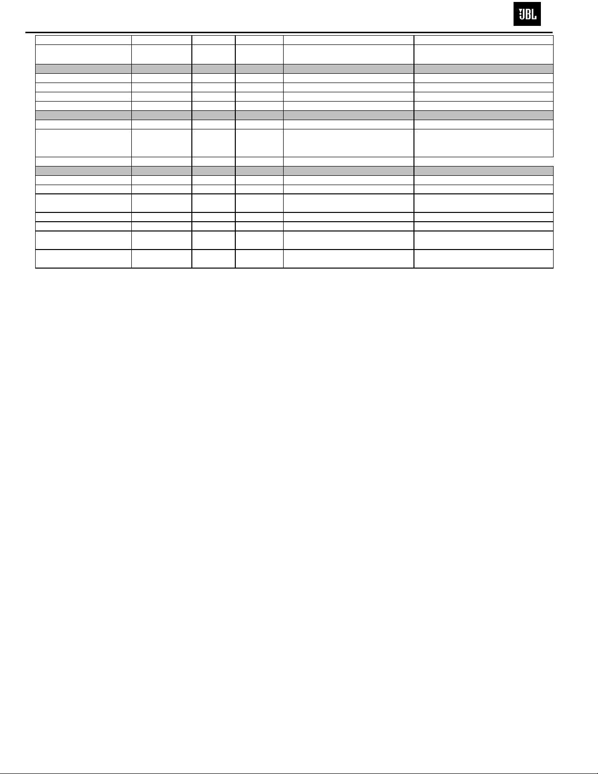
Parameter Specification Unit
Transients/Pops
ATO Transient 5 mV-peak
Turn-on Transient 50 mV-peak
Turn-off Transient 50 mV-peak
Efficiency
Stand-by Input Power 14 Watts
Power Cons.@rated power 250 Watts
Protection
Short Circuit Protection YES --
Thermal Protection 65 deg. C -DC Offset Protection YES -Line Fuse Rating
US Version 2.5 Amps
EU Version 1.6 Amps
QA Test
Limits Conditions Notes
10 @ Speaker Outputs
100 @ Speaker Outputs AC Line cycled from OFF to ON
100 @ Speaker Outputs AC Line cycled from ON to OFF
Maximum allowable input power under
15 @ nom. line voltage
260 @ nom. line voltage
functional Direct short at output
functional @1/8 max unclipped Power
functional DC present at Speaker Out leads Relay or crowbar (for driver/fire
Type-T or Slo Blo
Type-T or Slo Blo
nominal Input voltage and frequency,
HOT or COLD operation.
150 Watts @ 4 Ohms nominal line voltage
Temperature rise should not exceed 35K
rise
External fuse with UL/SEMKO rated
holder
External fuse with UL/SEMKO rated
holder
Page 5
10
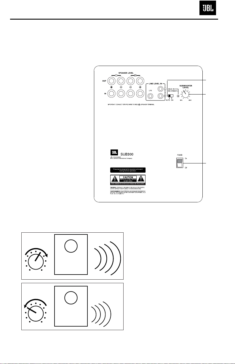
OPERATION
MIN MAX
Subwoofer
Level
MIN MAX
Subwoofer
Level
Move the Master Power switch
(marked “Power”
å) to the “•”
(On) position to use the subwoofer. The SUB300 subwoofer
will automatically turn on or go
into standby (sleep) mode
when left in the auto mode
(“Auto/On” switch
ç in the
“Auto” position). When your
receiver or amplifier is off, or is
not sending program material
to the subwoofer, the subwoofer will be in standby mode
(LED will be red). When the
sub
woofer senses an audio sig-
nal,
it will automatically turn on
(LED will be green). If the subwoofer does not sense a signal
after
approximately 20 minutes,
it will automatically go into
standby mode.
When the “Auto/On” switch
ç
is switched to the “On” position, the subwoofer will remain
on, whether or not program
material is playing.
If you will be away from home
for an extended period of time,
or if the subwoofer will not be
used, switch the Master Power
switch
å to the Off position.
VOLUME
Volume may be adjusted
using the Subwoofer Level
control
∫ as shown.
SUB300 (SCS300.7sys)
4
CAUTION
CAUTION
RISK OF ELECTRIC SHOCK
RISK OF ELECTRIC SHOCK
RISK OF ELECTRIC SHOCK
DO NOT OPE N
DO NOT OPE N
DO NOT OPE N
ç
∫
å
Page 6
8
DOLBY PRO LOGIC* (NON-DIGITAL)
–
LINE LEVEL
Use this installation method
for Dolby Pro Logic applications (not Dolby Digital, DTS
or other digital processing),
where the receiver/processor is equipped with a subwoofer output, or a volumecontrolled preamp (line-)
level output:
Use RCA-type interconnects
to connect the line-level
subwoofer outputs on your
receiver or amplifier to the
line-level inputs on the subwoofer. IMPORTANT: Do not
use the LFE input on the subwoofer with Dolby Pro Logic
processors.
NOTE: If your receiver or
amplifier only has one subwoofer output jack, then you
will need to use a Y-connector
(not included). Plug the male
end of the Y-connector into
your receiver or amplifier’s
subwoofer output jack, and
connect each of the two
female ends to separate
RCA-type interconnects.
Finally, plug the RCA-type
interconnects into the linelevel inputs on the subwoofer.
Connect each speaker to
the corresponding speaker
terminals on your receiver
or amplifier.
Make sure your receiver or
processor is correctly configured to indicate that the
subwoofer is “On.”
Note for advanced users: If
your receiver/processor has
a built-in low-pass crossover
filter for the subwoofer output, you may use the LFE
input to bypass the subwoofer’s internal crossover.
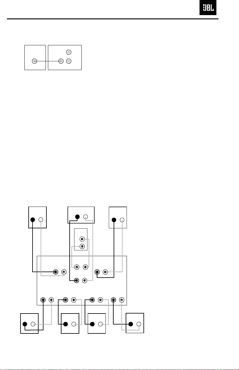
Use this installation method
for Dolby Digital, DTS or
other digital surround
processors:
Use the line-level input jack
marked “LFE” for the Low-
Frequency Effects channel.
Connect this jack to the LFE
output or subwoofer output
on your receiver or amplifier.
Connect each speaker to the
corresponding speaker
terminals on your receiver
or amplifier.
Make sure that you have
configured your surround
sound processor for “Subwoofer On.” Also configure
your receiver for 5.1-, 6.1or 7.1-channel operation as
appropriate. The front left,
front right, center and rear
speakers should all be set to
“Small.” If your receiver
allows you to set the
crossover frequency
between the subwoofer and
the main speakers, select
100Hz or the setting that is the
closest frequency below it.
DOLBY* DIGITAL OR DTS
®
(OR OTHER DIGITAL SURROUND MODE) CONNECTION
LINE
LEVEL
IN
LFE
L
R
LFE OUT
SUBWOOFER
RECEIVER
– +
– +
– +
– +
– +
– +
– +
– +– +
Receiver
Subwoofer
Out
Left
Front
Left
Surround
– +
Right
Front
Right
Surround
Subwoofer
R L
Center
Surround Back
Left
Line-
Level In
Right Surround
Right Front
Left Surround
Left Front
Center
R
L
– +
Surround Back
Left
– +
– +
Surround Back
Right
– +
Surround Back
Right
SUB300 (SCS300.7sys)
5
Page 7
9
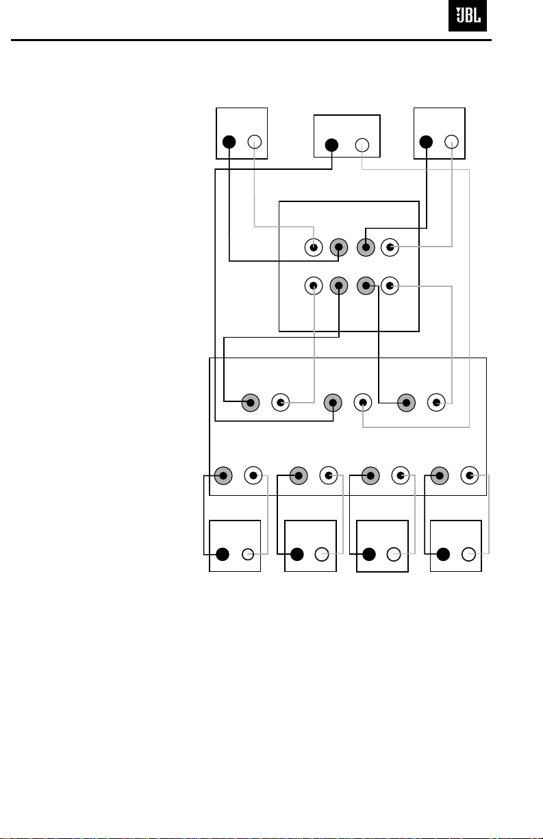
DOLBY PRO LOGIC (NON-DIGITAL) –SPEAKER LEVEL
Use this installation method
for Dolby Pro Logic applications (not Dolby Digital, DTS
or other digital processing),
where the receiver/processor
does not have a subwoofer
output, or a volume-controlled
preamp (line-) level output:
Connect your receiver or
amplifier’s front left and right
speaker terminals to the left
and right terminals on the
subwoofer that are marked
“Speaker Level In.” Connect
the left and right terminals on
the subwoofer that are
marked “Speaker Level Out”
to the corresponding terminals on the back of your front
left and right speakers.
Connect your receiver or
amplifier’s center, surround
and surround back speaker
terminals to the corresponding terminals on the back of
your center and surround
speakers.
Right Front
Right Surround
Left Front
Left Surround
Center
– + – +
– +
– + – +
– +
– +
– + – +
– +
Left Front Center
Left Surround
Right Front
Right Surround
Surround Back
Left
Surround Back
Left
Subwoofer
Receiver
SPEAKER LEVEL
L R
OUT
IN
+ – – +
– +
– +
Surround Back
Right
Surround Back
Right
– + – +
SUB300 (SCS300.7sys)
6
Page 8

If there is no sound from any
of the speakers:
• Check that receiver/amplifier is on and a source is
playing.
• Check that the powered
subwoofer is plugged in,
and its
Power switch å is
switched on (“•” position).
• Check all wires and connections between receiver/
amplifier and speakers.
Make sure all wires are connected. Make sure none of
the speaker wires are
frayed, cut or punctured, or
touching each other.
• Review proper operation of
your receiver/amplifier.
If there is no sound coming
from one speaker:
• Check the “Balance” control
on your receiver/amplifier.
• Check all wires and connections between receiver/
amplifier and speakers.
Make sure all wires are connected. Make sure none of
the speaker wires are
frayed, cut or punctured, or
touching each other.
• In Dolby Digital or DTS
modes, make sure that the
receiver/processor is configured so that the speaker in
question is enabled.
• Turn off all electronics
and switch the speaker in
question with one of the
other speakers that is working correctly. Turn everything back on, and determine whether the problem
has followed the speaker, or
has remained in the same
channel. If the problem is
in the same channel, the
source of the problem
is most likely with your
receiver or amplifier, and
you should consult the
owner’s manual for that
product for further information. If the problem has followed the speaker, consult
your dealer for further assistance or, if that is not possible, visit www.jbl.com.
If there is no sound from the
center speaker:
• Check all wires and connections between receiver/
amplifier and speaker. Make
sure all wires are connected.
Make sure none of the
speaker wires are frayed,
cut or punctured, or touching each other.
• If your receiver/processor
is set in Dolby Pro Logic mode,
make sure the center speaker
is not in phantom mode.
• If your receiver/processor
is set in one of the Dolby
Digital or DTS
modes, make
sure the receiver/
processor
is configured so that the
center speaker is enabled.
If the system plays at low
volumes but shuts off as
volume is increased:
• Check all wires and connections between receiver/
amplifier and speakers.
Make sure all wires are connected. Make sure none of
the speaker wires are
frayed, cut or punctured, or
touching each other.
• If more than one pair of
main speakers is being used,
check the minimum impedance requirements of your
receiver/amplifier.
If there is low (or no) bass
output:
• Make sure the connections
to the left and right “Speaker
Inputs” have the correct
polarity (+ and –).
• Make sure the subwoofer
is plugged into an active
electrical outlet
, and is
turned on (Power switch
å in the “
•
” position).
• In Dolby Digital or DTS
modes, make sure your
receiver/processor is configured so that the subwoofer
and LFE output are enabled.
If there is no sound from
the surround speakers:
• Check all wires and connections between receiver/
amplifier and speakers.
Make sure all wires are connected. Make sure none of
the speaker wires are
frayed, cut or punctured, or
touching each other.
• Review proper operation of
your receiver/amplifier and
its surround sound features.
• Make sure the movie or
TV show you are watching
is recorded in a surround
sound mode. If it is not,
check to see whether your
receiver/amplifier has other
surround modes you may use.
•
In Dolby Digital or DTS
modes, make sure your
receiver/processor is configured so that the surround
speakers are enabled. When
five satellites are in use,
remember to configure your
receiver or processor for
6.1-channel operation, and
when all six satellites are in
use, configure your receiver
or processor for 7.1 channels.
• Review the operation of
your DVD player and the
jacket of your DVD to make
sure that the DVD features
the desired Dolby Digital or
DTS mode, and that you
have properly selected that
mode using both the DVD
player’s menu and the DVD
disc’s menu.
TROUBLESHOOTING
11
SUB300 (SCS300.7sys)
7
Page 9

SUB300 (SCS300.7sys)
8
SUB300 TEST PROCEDURE
SYSTEM AURAL SWEEP TEST
Equipment needed:
• Function/signal generator/sweep generator
• Integrated Amplifier
• Multimeter
• Speaker cables
General Unit Function (UUT = Unit Under Test)
Auto-On switch – either position
1) From the signal generator, Connect both right and left line level inputs (RCA) to signal generator and UUT.
Use Y-cable if necessary from mono source. Do not use the LFE jack.
2) On the front of the unit, turn the LEVEL control full counterclockwise (MIN).
3) Turn on generator, adjust to 100mV, 50 Hz.
4) Plug in UUT; turn the power switch ON. Turn LEVEL control full clockwise (MAX)
5) LED should now be Green; immediate bass response should be heard and felt from port tube opening.
6) Turn off generator, turn LEVEL control fully counterclockwise (MIN), disconnect RCA cable.
7) Connect one pair of speaker cables to one pair Speaker Level input terminals on UUT. Cables should be
connected to an integrated amplifier fed by the signal generator.
8) Turn on generator and adjust so that speaker level input at the amplifier is 2.0V, 50 Hz.
9) Turn LEVEL control full clockwise (MAX)
10) Green LED should light, immediate bass response should be heard and felt from the port tube opening.
Sweep Function
1) Follow steps 7-10 above, using a sweep generator as a signal source.
2) Sweep generator from 20Hz to 1kHz. Listen to the cabinet and drivers for any rattles, clicks, buzzes or any
other noises. If any unusual noises are heard, remove woofer and test.
Driver Function (Woofer)
1) Remove woofer from cabinet; detach + and - wire clips.
2) Check DC resistance of woofer; it should be 3.4 ohms±10%.
3) Connect a pair of speaker cables to driver terminals. Cables should be connected to an integrated amplifier
fed by a signal generator. Turn on generator and adjust so that speaker level output is 5.0V.
4) Sweep generator from 20Hz to 1kHz. Listen to driver for any rubbing, buzzing, or other unusual noises.
Page 10

SUB300 (SCS300.7sys)
9
SUB300
Exploded View
SUB300 Amplifier
Not For Sale
SUB300 Cabinet
Not For Sale
Port Tube
249-ABS-00175
Main Body Plastic Foot (4)
321-ABS-00008
Foot Screw (4)
352-HM04030D500
Woofer & Amplifier Screw (15)
352-AM04020D210
10" Woofer DCR=3.4Ω
25MF12DZB-DW01
Rubber Foot Base (4)
321-ABS-00009
Page 11

SUB300 (SCS300.7sys)
10
Page 12

SUB300 (SCS300.7sys)
11
Page 13

SUB300 (SCS300.7sys)
12
Page 14

SUB300 (SCS300.7sys)
13
SUB300 120v Electrical parts List
Part Number Description Qty Reference Designator
Input/Main PCBs
Resistors
110-14103j26 resistor 10K 1/4W ± 5% CF 26mm 3 R503,504,10
110-14222j26 resistor 2.2K 1/4W ± 5% CF 26mm 1
110-14432j26 resistor 4.3K 1/4W ± 5% CF 26mm 1 R506
110-14472j26 resistor 4.7K 1/4W ± 5% CF 26mm 1 R505
110-16102j26
110-16103j26 resistor 10K 1/6W ± 5% CF 26mm 28
110-16104j26
110-16105j26
110-16122j26
110-16124j26
110-16151j26
110-16153j26
110-16154j26
110-16182j26
110-16183j26
110-16203j26
110-16205j26
110-16221j26
110-16222j26
110-16223j26
110-16273j26
110-16333j26
110-16393j26
110-16472j26
110-16473j26
110-16474j26
110-16512j26
110-16513j26
110-16562j26
110-16621j26
110-16751j26
110-16755j26
110-16913j26
116-161002f26
116-161102f26
116-162200f26
116-162202f26
110-12472j52 resistor 4.7K 1/2W ± 5% CF 52mm 2 R201,202
110-20332jk2 resistor 3.3K 2W ± 5% CF 7.5mm 1 R134
113-50s68j00 cement resistor 0.068Ω 5W ± 5% 7.5mm 1 R147
115-h503a102 variable resistor RV16AE-20B2 -A54-104 LEVEL 1 VR201
116-201001jk3x metal film resistor 1.00K ± 5% 2W 7.5mm 1 R148
116-304700jk2x metal film resistor 470Ω ± 5% 3W 10mm 2 R501,502
resistor 1K 1/6W ± 5% CF 26mm
resistor 100K 1/6W ± 5% CF 26mm
resistor 1M 1/6W ± 5% CF 26mm
resistor 1.2K 1/6W ± 5% CF 26mm
resistor 120K 1/6W ± 5% CF 26mm
resistor 150Ω 1/6W ± 5% CF 26mm
resistor 15K 1/6W ± 5% CF 26mm
resistor 150K 1/6W ± 5% CF 26mm
resistor 1.8K 1/6W ± 5% CF 26mm
resistor 18K 1/6W ± 5% CF 26mm
resistor 20K 1/6W ± 5% CF 26mm
resistor 2M 1/6W ± 5% CF 26mm
resistor 220Ω 1/6W ± 5% CF 26mm
resistor 2.2K 1/6W ± 5% CF 26mm
resistor 22K 1/6W ± 5% CF 26mm
resistor 27K 1/6W ± 5% CF 26mm
resistor 33K 1/6W ± 5% CF 26mm
resistor 39K 1/6W ± 5% CF 26mm
resistor 4.7K 1/6W ± 5% CF 26mm
resistor 47K 1/6W ± 5% CF 26mm
resistor 470K 1/6W ± 5% CF 26mm
resistor 5.1K 1/6W ± 5% CF 26mm
resistor 51K 1/6W ± 5% CF 26mm
resistor 5.6K 1/6W ± 5% CF 26mm
resistor 620Ω 1/6W ± 5% CF 26mm
resistor 750Ω 1/6W ± 5% CF 26mm
resistor 7.5M 1/6W ± 5% CF 26mm
resistor 91K 1/6W ± 5% CF 26mm
metal film resistor 10K 1/6W ± 1% MF 26mm
metal film resistor 11.0Ω 1/6W ± 1% MF 26mm
metal film resistor 220Ω 1/6W ± 1% MF 26mm
metal film resistor 22.0K 1/6W ± 1% MF 26mm
R511
5 R153,213,214,215,254
R128,13,0149,150,209,212,216,217,220,221,222,225,226,
227,228,229,230,232,240,248,260,305,306,308,311,314,
319,325
6 R122,126,231,263,266,307
1 R259
1 R265
1 R233
1 R253
2 R107,234
1 R252
1 R145
1 R262
1 R309
1 R257
1 R144
1 R102
5 R238,247,255,256,316
2 R223,237
1 R310
1 R151
3 R200,207,58
7 R106,129,219,249,250,251,264
2 R127,312
2 R210,211
1 R224
1 R152
1
R160
1
R315
1
R313
4
R203,204,205,206
2 R301,303
1 R302
1 R317
1 R318
Capacitors
129-a154j633
130-2b221k503
130-2b470k503
130-2f104z503 disc capacitor 0.1U 50V +80/-20% 14 C17,117,122,144,232,242,244,245,246,252,254,256,320, 322
130-sl101k503
132-103j503 mylar capacitor 0.01U 50V ± 5% 4 C223,224,305,317
132-103ja03
132-104ja03
132-223ja03
132-273ja03
132-473ja03
135-3105m50
135-3106m50
135-3107m10
metallize capacitor 0.15U 63V ± 5% MSC
disc capacitor 220P 50V ± 10%
disc capacitor 47P 50V ± 10%
disc capacitor 100P 50V SL ± 10%
mylar capacitor 0.01uF 100V ± 5%
mylar capacitor 0.1uF 100V ± 5%
mylar capacitor 0.022uF 100V ± 5%
mylar capacitor 0.027uF 100V ± 5%
mylar capacitor 0.047uF 100V ± 5%
electrolytic 1U 50V ± 20%
electrolytic 10uF 50V ± 20%
electrolytic 100U 10V ± 20%
2 C221,222
12 C200,204,205,207,208,210,211,212,214,220,230,249
1 C229
3 C302,303,306
2 C103,104
4 C123,218,503,504
1 C215
1 C143
2 C216,217
1 C228
12 C201.202.206.213.219.231.241.243.251.253.319.321
2 C114,115
Page 15

SUB300 (SCS300.7sys)
14
Part Number Description Qty Reference Designator
120v Electrical parts List cont'd
Input/Main PCBs
135-3107m16
135-3107m35
135-3225m50
135-3226m16
135-3226m50
135-3227m16
135-3476m16
132-103kb00 mylar capacitor 0.01uF 200V ± 10% 1 C500
135-4478m63 electrolytic cap 4700uF 63V ± 20% 2 C501,502
Semiconductors
192-027c1815gr transistor 2SC1815GR NPN 9 Q108,109,113,201,206,207,208,301,302
192-027c2235y transistor 2SC2235Y NPN 1 Q111
192-028a1015gr transistor 2SA1015GR PNP 3 Q101,107,112
192-1672n5551 transistor 2N5551 NPN 2 Q114,115
192-1682n5401 transistor 2N5401 AI-PNP 350V 500mA TO-92 1 Q503
197-031n4148 diode 100mA 75V SIGNAL 1N4148 ROHM 20
199-15000335 zener diode 3.3V 1/2W 52mm 1 D213
199-15000625 zener diode 6.2V 1/2W 52mm 1 D101
199-15001605 zener diode 16V 1/2W 52mm 1 D502
190-06m4558d IC OPA 4558D DUAL OP-AMP 1 U203
190-16t1074cn IC TL074CN ST QUAD OP-AMP 3 U201,202,301
192-161tip31c transistor TIP31C SGS NPN 1 Q501
192-162tip32c transistor TIP32C SGS PNP 1 Q502
195-10204hgw LED 204HGW 1 D209
197-00kbu606g diode 6A 800V KBU606G 1 D501
197-141n4004 diode 1N4004 2 D110,504
electrolytic 100uF 16V ± 20%
electrolytic 100U 35V ± 20%
electrolytic 2.2U 50V ± 20%
electrolytic 22U 16V ± 20%
electrolytic 22U 50V ± 20%
electrolytic 220U 16V ± 20%
electrolytic 47U 16V ± 20%
1 C234
2 C507,508
1 C509
1 C304
3 C225,505,506
2 C118,233
1 C318
D102,103,104,105,143,201,202,203,204,205,206,207,208,
211,212,214,215,216,302,302
Miscellaneous
109-1ttc802j0 thermister TTC-802(JS) NTC 1 TH1
120-1000003
162-10060003
162-50129001 wire cable ass'y 120mm AWG28 WHT 1 W201
171-urwh124d relay RWH-SH-124D (1600ohm) 1 RL1
174-0rca108gv jack RCA-108GV JK203 1 JK201
174-0rcb202vg jack RCA JK RCB-202VD(G) A=WHIT/B=RED 1 JK202
174-20810360g jack spk JK BP 8PIN SH0810360G US1.35 1 JK203
175-1c07v01 wire connector 7PIN PITCH=2.5mm 1 M201
180-tms7210v
inductor 10W AI YT-C3104-005 1CRHW 354708LTB 2 FB1,2
wire 60mm S412P
switch slide 6PIN MS7210V
1 J104 TO W2
1 SW201
Power Amp Class D Module part# 012-7500-00022 RECOMMENDED: REPLACE ENTIRE MODULE
Resistors
118-12061001j SMD resistor 1.00K 1206 5% 4 R2,11,29,30
118-12061002j SMD resistor 10.0K 1206 5% 3 R7,9,25
118-120610r0j SMD resistor 10.0Ω1206 5% 2 R22,23
118-12061201j SMD resistor 1.20K1206 5% 16 R31,32,33,34,35,36,37,38,39,40,41,42,43,44,45,46
118-12062002j SMD resistor 20.0K1206 5% 1 R26
118-12062201j SMD resistor 2.20K 1206 5% 3 R6,13,16
118-12062701j SMD resistor 2.70K 1206 5% 1 R10
118-12063000j SMD resistor 300.0Ω 1206 5% 1 R24
118-12063301j SMD resistor 3.30K 1206 5% 4 R14,15,27,28
118-12063902j SMD resistor 39.0K 1206 5% 1 R3
118-12064700j SMD resistor 470Ω 1206 5% 1 R8
118-12064701j SMD resistor 4.70K 1206 5% 3 R1,5,12
118-12064702j SMD resistor 47.0K 1206 5% 1 R17
118-12064704j SMD resistor 4.70M 1206 5% 1 R4
118-120647r0j SMD resistor 47.0Ω 1206 5% 2 R20,21
Page 16

SUB300 (SCS300.7sys)
15
Part Number Description Qty Reference Designator
120v Electrical parts List cont'd
Module Class D DS-150
Capacitors
141-c0101k50 SMD capacitor 100pF 50V 10% 1206 NP0 1 C4
141-c0220k50 SMD capacitor 22pF 50V 10% 1206 SMT NP0 1 C5
141-c0561k50 SMD capacitor 560pF 50V 10% 1206 NP0 1 C6
141-c5104m50 SMD capacitor 1206 Y5V 0.1uF 50V ± 20% 8 C2,3,7,8,9,10,11,15
141-c7223k50 SMD capacitor 0.022uF 50V 10% 1206 X7R 1 C13
141-d7104ka0 SMD capacitor 0.1uF 100V 10% 1206 X7R 2 C12,14
141-d7104ka5 SMD capacitor 0.1uF 250V 10% 1210 X7R 4 C1,18,19,20
128-e106ma01
Semiconductors
190-16tl072dts SMD I.C TL072CDT SGS DUAL OP-AMP 1 IC1
192-09124126qs SMD transistor 2SC2412K-T146Q/R ROHM 3 Q1,4,5
192-09139066rs SMD transistor 2SC3906K-T146R ROHM 2 Q2,8
192-09210376qd SMD transistor 2SA1037K-T146Q/R ROHM 2 Q7,9
192-09215146rs SMD transistor 2SA1514K-T146R ROHM 2 Q3,6
197-03rls4148s SMD diode RLS4148-TE11 ROHM 6 D1,2,3,4,5,6
199-15000563s SMD zener diode 5.6V 5% PHILIPS BZX84-C5V6 2 Z1,2
199-15001203s SMD zener diode 12V 5% PHILIPS BZX84-C12 2 Z5,6
199-15001503s SMD zener diode 15V 5% PHILIPS BZX84-C15 2 Z3,4
192-232irf9640 transistor FET IRF9640 IR P-CH TO220 1 Q10
192-233irf640
non-polar 10uF 100V 20%
transistor FET IRF640 IR P-CH TO220
2 C16,17
1 Q11
Miscellaneous
122-14121m4191
122-14350j4180
175-9f40hr2 wire connector 40PIN PITCH=2.54mm HR2*40
MISCELLANEOUS
130-2f104z503 disc capacitor 0.1U 50V +80/-20% TAP 1 C110
150-r4055900 power transformer I/P: 120V/60Hz TT0900008720 1 T501
152-u602015 line cord SVT FT-26FT 1
154-k31505t0 fuse 3.15A 250V 30mm UL/CSA/PSE 1 F501
155-63032i fuse holder HTB-32I 30mm UL/CSA 1 for 501
162-10082007 wire RED 18AWG 8mm#1015 1
162-a040d001 wire #1515 400mm 9911110-00 1
176-wjce1 wire connector pin CE-1 1
180-pbr12c11s switch PUSH BR12C11S 1 SW501
193-201815t2 insulator 1
302-AL-00020-0LC Alu. Panel 1
306-ABS-00004 Rear cover 1
311-ABS-00028 Plastic switch 1
317-000-00037 Terminal 1
323-AL-00056 Heat sink 1
333-EVA-00096 EVA (Gasket) 2
333-EVA-00097 EVA (Gasket) 2
333-EVA-00132 EVA (Gasket) 2
333-EVA-00133 EVA (Gasket) 2
333-EVA-00188 EVA (Gasket) 1
333-EVA-00219 EVA (Gasket) 1
333-EVA-00220 EVA (Gasket) 1
335-NYL-00002 Cable sheet 2
350-EM04012D024 Screw 4
351-AM03008A078 Screw 4
351-AM03008A079 Screw 2
352-AM03008D040 Screw 2
352-AM03008D041 Screw 2
352-AM03040D065 Screw 4
352-HM03012D086 Screw 1
362-FE-00013 PCB holder 2
inductor ferrite core LS-A6206-ST EFD-30
inductor 35uH ferrite core 25 milliohm
1L1
1L2
Page 17

r
n
r
SUB300 (SCS300.7sys)
16
SUB300 230v Electrical parts List
Part Numbe
Descriptio
Input/Main PCBs
Resistors
110-14103j26 Resistor 10K 1/4W ± 5% CF 26mm TAP
110-14222j26 Resistor 2.2K 1/4W ± 5% CF 26mm TAP
110-14432j26 Resistor 4.3K 1/4W ± 5% CF 26mm TAP
110-14472j26 Resistor 4.7K 1/4W ± 5% CF 26mm TAP
110-16102j26
110-16103j26 Resistor 10K 1/6W ± 5% CF 26mm TAP
110-16104j26
110-16105j26
110-16122j26
110-16124j26
110-16151j26
110-16153j26
110-16154j26
110-16182j26
110-16183j26
110-16203j26
110-16205j26
110-16221j26
110-16222j26
110-16223j26
110-16273j26
110-16333j26
110-16393j26
110-16472j26
110-16473j26
110-16474j26
110-16512j26
110-16513j26
110-16562j26
110-16621j26
110-16751j26
110-16755j26
110-16913j26
116-161002f26
116-161102f26
116-162200f26
116-162202f26
110-12472j26 Resistor 4.7K 1/2W ± 5% CF 52mm TAP
110-20332jk3
113-50s68j00 cement Resistor 0.068Ω 5W ± 5%
115-h503a102 variable Resistor RV16AE-20B2 -A54-104(A50K)
116-201001jk3x metal film Resistor 1.00K 2W± 5% 7.5mm
116-304700jk2x metal film Resistor 470Ω 3W± 5% 10mm
Resistor 1K 1/6W ± 5% CF 26mm TAP
Resistor 100K 1/6W ± 5% CF 26mm TAP
Resistor 1M 1/6W ± 5% CF 26mm TAP
Resistor 1.2K 1/6W ± 5% CF 26mm TAP
Resistor 120K 1/6W ± 5% CF 26mm TAP
Resistor 150Ω 1/6W ± 5% CF 26mm TAP
Resistor 15K 1/6W ± 5% CF 26mm TAP
Resistor 150K 1/6W ± 5% CF 26mm TAP
Resistor 1.8K 1/6W ± 5% CF 26mm TAP
Resistor 18K 1/6W ± 5% CF 26mm TAP
Resistor 20K 1/6W ± 5% CF 26mm TAP
Resistor 2M 1/6W ± 5% CF 26mm TAP
Resistor 220Ω 1/6W ± 5% CF 26mm TAP
Resistor 2.2K 1/6W ± 5% CF 26mm TAP
Resistor 22K 1/6W ± 5% CF 26mm TAP
Resistor 27K 1/6W ± 5% CF 26mm TAP
Resistor 33K 1/6W ± 5% CF 26mm TAP
Resistor 39K 1/6W ± 5% CF 26mm TAP
Resistor 4.7K 1/6W ± 5% CF 26mm TAP
Resistor 47K 1/6W ± 5% CF 26mm TAP
Resistor 470K 1/6W ± 5% CF 26mm TAP
Resistor 5.1K 1/6W ± 5% CF 26mm TAP
Resistor 51K 1/6W ± 5% CF 26mm TAP
Resistor 5.6K 1/6W ± 5% CF 26mm TAP
Resistor 620Ω 1/6W ± 5% CF 26mm TAP
Resistor 750Ω 1/6W ± 5% CF 26mm TAP
Resistor 7.5M 1/6W ± 5% CF 26mm TAP
Resistor 91K 1/6W ± 5% CF 26mm TAP
metal film Resistor 10K 1/6W ± 1% MF 26mm TAP
metal film Resistor 11.0K 1/6W ± 1% MF 26mm TAP
metal film Resistor 220Ω 1/6W ± 1% MF 26mm TAP
metal film Resistor 22.0K 1/6W ± 1% MF 26mm TAP
Resistor 3.3K 2W ± 5% 7.5mm
QtyReference Designato
3 R503,504,510
R511
1
1 R506
1 R505
5 R153,213,214,215,254
R128,130,149,150,209,212,216,217,220,221,222,225,226,
227,228,229,230,232,235,240,248,260,305,306,308,311,
28
314,319
6 R122,126,231,263,266,307
1 R259
1 R265
1 R233
1 R253
2 R107,234
1 R252
1 R145
1 R262
1 R309
1 R257
1 R144
1 R102
5 R238,247,255,256,316
2 R223,237
1 R310
1 R151
3 R200,207,258
7 R106,129,219,249,250,251,264
2 R127,312
2 R210,211
1 R224
1 R152
1
R160
1
R315
1
R313
4
R203,204,205,206
2 R301,303
1 R302
1 R317
1 R318
2 R201,202
1 R134
1 R147
1 VR201
1 R148
2 R501,502
Capacitors
129-a154j633
130-2b221k503
130-2b470k503
130-3f104z503 disc capacitor 0.1U 50V +80/-20% TAP
130-sl101k503
132-103j503 Mylar capacitor 0.01UF 50V ± 5% TAP
132-104ja03
132-223ja03
metallize capacitor 0.15U 63V ± 5% MSC TAP
disc capacitor 220P 50V ± 10% TAP
disc capacitor 47P 50V ± 10% TAP
disc capacitor 100P 50V SL ± 10% TAP
Mylar capacitor 0.1uF 100V ± 5% TAP
Mylar capacitor 0.022uF 100V ± 5% TAP
2 C221,222
12 C200,204,205,207,208,210,211,212,214,220,230,249
1 C229
C107,117,122,144,232,242,244,245,246,252,254,256,320,
14
322
3 C302,303,306
4 C223,224,305,317
4 C123,218,503,504
1 C215
Page 18

r
n
r
SUB300 (SCS300.7sys)
17
230v Electrical parts List cont'd
Part Numbe
Descriptio
Input/Main PCBs
132-273ja03
132-473ja03
135-3105m50
135-3106m50
135-3107m10
135-3107m16
135-3107m35
135-3225m50
135-3226m16
135-3226m50
135-3227m16
135-3476m16
129-a105ja04
132-103kb00 Mylar capacitor 0.01uF 200V ± 10% TAP
135-4478m63 electrolytic cap 4700uF 63V ± 20%
Semiconductors
192-027c1815gr transistor 2SC1815GR NPN
192-027c2235y transistor 2SC2235Y NPN
192-028a1015gr transistor 2SA1015GR PNP
192-1572n5551 transistor 2N5551 NPN
192-1582n5401 transistor 2N5401 AI-PNP 350V 500mA TO-92
197-031n4148 diode 100mA 75V SIGNAL 1N4148 ROHM TAP
199-15000335 zener diode 3.3V 1/2W 52mm TAP
199-15000625 zener diode 6.2V 1/2W 52mm TAP
199-15001605 zener diode 16V 1/2W 52mm TAP
190-06m4558d IC OPA 4558D DUAL OP-AMP
190-16t1074cn IC TL074CN ST QUAD OP-AMP
192-161tip31c transistor TIP31C SGS NPN
192-162tip32c transistor TIP32C SGS PNP
195-10204hgw LED 204HGW
197-00kbu606g diode 6A 800V KBU606G
197-141n4004 diode 1N4004
Mylar capacitor 0.027uF 100V ± 5% TAP
Mylar capacitor 0.047uF 100V ± 5% TAP
electrolytic 1U 50V ± 20% TAP
electrolytic 10uF 50V ± 20% TAP
electrolytic 100U 10V ± 20% TAP
electrolytic 100uF 16V ± 20% TAP
electrolytic 100U 35V ± 20% TAP
electrolytic 2.2U 50V ± 20% TAP
electrolytic 22U 16V ± 20% TAP
electrolytic 22U 50V ± 20% TAP
electrolytic 220U 16V ± 20% TAP
electrolytic 47U 16V ± 20% TAP
metallize capacitor 1U 100V
QtyReference Designato
1 C143
2 C216,217
1 C228
12 C201.202.206.213.219.231.241.243.251.253.319.321
2 C114,115
1 C234
2 C507,508
1 C509
1 C304
3 C225,505,506
2 C118,233
1 C318
2 C103,104
1 C500
2 C501,502
9 Q108,109,113,201,206,207,208,301,302
1 Q111
3 Q101,107,112
2 Q114,115
1 Q503
D102,103,104,105,143,201,202,203,204,205,206,207,208,
20
211,212,214,215,216,301,302
1 D213
1 D101
1 D502
1 U203
3 U201,202,301
1 Q501
1 Q502
1 D209
1 D501
2 D110,504
Miscellaneous
109-1ttc802j0
162-10060003
162-50129001 wire cable ass'y 120mm AWG28 WHT
171-urwh124d relay RWH-SH-124D (1600ohm)
174-0rca108gv jack RCA-108GV JK203
174-0rcb202ag jack RCA JKCA-209
174-20810360gx jack spk JK BP 8PIN SH0810360GX
175-1c07v01 wire connector 7PIN PITCH=2.5mm
175-1d02v01 wire connector 2PIN PITCH=3.96mm
175-1d03v01 wire connector 3PIN PITCH=3.96mm JST-VH
180-tms7210v
120-1000003 inductor 10W AI YT-C3104-005 1CRHW 354708LTB
thermister TTC-802(JS) NTC
wire 60mm S412P
switch slide 6PIN MS7210V
Module Class D DS-150
Resistors
118-12061001j SMD Resistor 1.00K 1206 5%
118-12061002j SMD Resistor 10.0K 1206 5%
118-120610r0j SMD Resistor 10.0Ω1206 5%
118-12061201j SMD Resistor 1.20K1206 5%
118-12062002j SMD Resistor 20.0K1206 5%
118-12062201j SMD Resistor 2.20K 1206 5%
1 TH1
1 J104
1 W201
1 RL1
1 JK201
1 JK202
1 JK203
1 M201
1 M100
1 M500
1 SW201
2 FB1,2
4 R2,11,29,30
3 R7,9,25
2 R22,23
16 R31,32,33,34,35,36,37,38,39,40,41,42,43,44,45,46
1 R26
3 R6,13,16
Page 19

r
n
r
y
E
y
P
r
F
E
#
#
6
0
SUB300 (SCS300.7sys)
18
230v Electrical parts List cont'd
Part Numbe
Descriptio
QtyReference Designato
Module Class D DS-150
118-12062701j SMD Resistor 2.70K 1206 5% 1 R10
118-12063000j SMD Resistor 300.0Ω 1206 5%
118-12063301j SMD Resistor 3.30K 1206 5%
118-12063902j SMD Resistor 39.0K 1206 5%
118-12064700j SMD Resistor 470Ω 1206 5%
118-12064701j SMD Resistor 4.70K 1206 5%
118-12064702j SMD Resistor 47.0K 1206 5%
118-12064704j SMD Resistor 4.70M 1206 5%
118-120647r0j SMD Resistor 47.0Ω 1206 5%
Capacitors
141-c0101k50 SMD capacitor 100pF 50V 10% 1206 NP0
141-c0220k50 SMD capacitor 22pF 50V 10% 1206 SMT NP0
141-c0561k50 SMD capacitor 560pF 50V 10% 1206 NP0
141-c5104m50 SMD capacitor 1206 Y5V 0.1uF 50V ± 20%
141-c7223k50 SMD capacitor 0.022uF 50V 10% 1206 X7R
141-d7104ka0 SMD capacitor 0.1uF 100V 10% 1210 X7R
141-d7104ka5 SMD capacitor 0.1uF 250V 10% 1210 X7R
128-e106ma01
Semiconductors
non-polar 10uF 100V 20%
1 R24
4 R14,15,27,28
1 R3
1 R8
3 R1,5,12
1 R17
1 R4
2 R20,21
1 C4
1 C5
1 C6
8 C2,3,7,8,9,10,11,15
1 C13
2 C12,14
4 C1,18,19,20
2 C16,17
190-16tl072dts SMD I.C TL072CDT SGS DUAL OP-AMP
192-09124126qs SMD transistor 2SC2412K-T146Q/R ROHM
192-09139066rs SMD transistor 2SC3906K-T146R ROHM
192-09210376qd SMD transistor 2SA1037K-T146Q/R ROHM
192-09215146rs SMD transistor 2SA1514K-T146R ROHM
197-03rls4148s SMD diode RLS4148-TE11 ROHM
199-15000563s SMD zener diode 5.6V 5% PHILIPS BZX84-C5V6
199-15001203s SMD zener diode 12V 5% PHILIPS BZX84-C12
199-15001503s SMD zener diode 15V 5% PHILIPS BZX84-C15
192-232irf9640 transistor FET IRF9640 IR P-CH TO220
192-233f640
Miscellaneous
175-9f40hr2 wire connector 40PIN PITCH=2.54mm HR2*40
122-14121m4191
122-14350j4180
transistor FET IRF640 IR P-CH TO220
inductor ferrite core LS-A6206-ST EFD-30
inductor 35uH ferrite core 25 milliohm
1 IC1
3 Q1,4,5
2 Q2,8
2 Q7,9
2 Q3,6
6 D1,2,3,4,5,6
2 Z1,2
2 Z5,6
2 Z3,4
1 Q10
1 Q11
0.2
1 L1
1 L2
FILTER PCB ASS'Y
122-14103m4200
132-104kb70 m
132-224kb70 m
inductor RT251510*103N 10mH
lar capacitor 0.1uF 275V ± 10% VD
lar capacitor 0.22uF 275V ± 10% 1 C498
2 L501
1 C499
MISCELLANEOUS
130-3f104z503 disc capacitor 0.1U 50V +80/-20% TA
150-r4055901 230v power transforme
152-v60202603 line cord 6FT SPO21A H03VVH2154-k16006t0 fuse 1.6A 250V VBS UTE-TYPE UL/BSI/VDE 1 F501
155-620001 fuse holder HTB-32M UL/CSA/VD
162-10121002 wire UL1617 120mm BRN 20
162-10126001 wire UL1617 120mm BLU 20
162-10152001 wire UL1617 AGW22 150mm RED 6:
162-a040d001 wire #1015 400mm 991110-0
180-prf1003d switch ROCK RF-1003-BB4-O POWER 1
193-201815t2 insulator 1
1 C110
1 T501
1
1 for F501
1
1
1
1 M100
Page 20

SUB300 (SCS300.7sys)
19
Page 21

SUB300 (SCS300.7sys)
20
120v SCHEMATIC PAGE 1
Page 22

SUB300 (SCS300.7sys)
21
120v SCHEMATIC PAGE 2
Page 23

SUB300 (SCS300.7sys)
22
120v SCHEMATIC PAGE 3
Page 24

SUB300 (SCS300.7sys)
23
230v SCHEMATIC PAGE 1
Page 25

SUB300 (SCS300.7sys)
24
230v SCHEMATIC PAGE 2
Page 26

SUB300 (SCS300.7 sys)
25
SCS300.7
Packaging
Warranty Card
Speaker Wire 20 Feet (3)
166-020F84XX
Speaker Wire 40 Feet (4)
166-040F84XX
Speaker Wire 15 Feet (2)
166-015F84XX
RCA Cable 15 Feet
166-015F011
1
405-000-00258
Owner’s Manual
(120V) 406-000-00959
(230V) 406-000-00958
Floor Stand Adapter (6)
325-ABS-00436
Wall-Mount Bracket
(Sats & Center) (7)
326-ABS-05013
Center Shelf Stand
398-ABS-05043
Sat Shelf Stand (6)
398-ABS-05042
Hardware Bag A
371-000-05024
Hardware Bag B
371-000-05027
Screw (6)
354-GC250703
Sat/Center Packing
431-000-05031
1
Sub Packing
431-000-05034
SCS300.7 Outer Carton
(120V) 402-000-01822
(230V) 402-000-05066
 Loading...