

Jbl Professional Sound System Service Manual Part 2

Sound System Design Reference Manual
Chapter 6: Behavior of Sound Systems Indoors
Introduction
The preceding five chapters have provided the
groundwork on which this chapter is built. The “fine
art and science” of sound reinforcement now begins
to take shape, and many readers who have patiently
worked their way through the earlier chapters will
soon begin to appreciate the disciplines which have
been stressed.
The date at which sound reinforcement grew
from “public address by guesswork” to a methodical
process in which performance specifications are
worked out in advance was marked by the
publication in 1969 of a paper titled “The Gain of a
Sound System,” by C. P. and R. E. Boner (4). It
describes a method of calculating potential sound
system gain, and that method has since become a
fundamental part of modern sound system design.
The following discussion is based on the Boner
paper. Certain points are expanded, and examples
are given that require calculations more complicated
than those in the original study. Also discussed is the
relation between theoretically achievable system
gain and practical operating parameters of typical
indoor sound systems.
Figure 6-1. An indoor sound system
6-1

Sound System Design Reference Manual
Acoustical Feedback and Potential
System Gain
Just as in the outdoor case studied earlier,
if we have a microphone/amplifier/loudspeaker
combination in the same room and gradually turn up
the gain of the amplifier to a point approaching
sustained feedback, the electrical frequency
response of the system changes with the gain
setting. The effect results from an acoustic feedback
path between the loudspeaker and the microphone.
As a person talks into the microphone, the
microphone hears not only the direct sound from the
talker, but the reverberant field produced by the
loudspeaker as well.
The purpose of using high-quality loudspeakers
and microphones having smooth response
characteristics, and sound system equalization (apart
from achieving the desired tonal response) is to
smooth out all of the potential feedback points so
that they are evenly distributed across the audible
frequency range. When this has been done, there
should be as many negative feedback points as
positive feedback points, and the positive feedback
points should all reach the level of instability at about
the same system gain.
We might expect this to average out in such a
way that the level produced by the loudspeaker
reaching the microphone can never be greater than
that produced by the talker without causing sustained
oscillation. In other words, we assume that the extra
gain supplied by all the positive feedback spikes is
just balanced out by the loss caused by all the
negative feedback dips.
If the Boner criteria for optimum system
geometry are followed, the microphone will be close
to the talker so that it hears mostly direct sound from
the talker. It will be far enough from the loudspeaker
to be well into the reverberant field of the
loudspeaker, so that direct sound from the
loudspeaker is not an appreciable factor in triggering
system feedback. Assuming that listeners are also in
the reverberant field of the loudspeaker, it follows
that the sound level in the listening area with the
system turned on cannot be greater than that of the
unaided talker at the microphone position with the
system turned off. Using the Boner concept of
system delta, the situation at maximum gain
corresponds to a delta of unity. (Delta is defined as
the difference in decibels between sound level at the
system microphone with system off and the level in
the audience area with system on. See Figure 6-1).
Although we have described these as
conditions of maximum potential system gain, it is
possible in practice to achieve a delta greater than
unity. For example, if a directional microphone is
used it can discriminate against the reverberant field
and allow another 3 to 4 dB of system gain. Another
possibility is to place the listener in the direct field of
the loudspeaker, allowing a further increase in
system gain. If the level of the reverberant field is
lower in the performing area than in the listening
area, additional system gain also results. This
situation is described by the Boners as a room
constant in the microphone area different from that in
the seating area. Similar results may be noted in
rooms having large floor areas, relatively low
ceilings, and substantial sound absorption. In such
rooms, as we have seen, sound from a point source
tends to dwindle off beyond D
for each doubling of distance rather than remaining
constant in level.
Still another way to increase gain is to
electrically suppress the positive feedback
frequencies individually with very narrow bandwidth
filters. If one could channel all energy into the
negative feedback frequencies, the potential system
gain would theoretically become infinite! Unfortunately,
the acoustic feedback path is not stable enough to
permit this degree of narrow-band equalization.
In all other situations, a gain setting is reached
at which sustained oscillation occurs. By definition,
maximum system gain is reached just below this
point. However, the system cannot be operated
satisfactorily at a point just below oscillation because
of its unpleasant comb-filter response and the
prolonged ringing caused by positive feedback
peaks. To get back to reasonably flat electrical
response and freedom from audible ringing, it usually
is recommended that a properly equalized system be
operated about 6 dB below its maximum gain point.
Even an elaborately tuned system using narrowband filters can seldom be operated at gains greater
than 3 dB below sustained oscillation.
at a rate of 2 or 3 dB
C
Sound Field Calculations for a Small Room
Consider the room shown in Figure 6-2. This is
a typical small meeting room or classroom having a
volume less than 80 m3. The average absorption
coefficient a is 0.2. Total surface area is 111 m2. The
room constant, therefore, is 28 m2.
From the previous chapter, we know how to
calculate the critical distance for a person talking
(nominal directivity index of 3 dB). In the example
given, DC for a source having a directivity index of 3
dB is 1 meter.
The figure also shows geometrical relationships
among a talker, a listener, the talker’s microphone
and a simple wall-mounted loudspeaker having a
directivity index of 6 dB along the axis pointed at the
listener. The microphone is assumed to be
omnidirectional.
6-2

Sound System Design Reference Manual
Step 1: Calculate relative sound levels produced
by the talker at microphone and listener.
We begin with the sound system off. Although
the calculations can be performed using only relative
levels, we will insert typical numbers to get a better
feel for the process involved.
The microphone is .6 meter from the talker, and
at this distance, the direct sound produces a level of
about 70 dB. Since D
for the unaided talker is only
C
1 meter, the microphone distance of .6 meter lies in
the transition zone between the direct field and the
reverberant field of the talker. By referring to Figure
6-3, we note that the combined sound levels of the
reverberant field and the direct field at a distance of
.6 meter must be about 1 dB greater than the direct
field alone. Therefore, since we have assumed a
level of 70 dB for the direct field only, the total sound
level at the microphone must be 71 dB.
Next, we use a similar procedure to calculate
the sound level at the listener’s position produced by
an unaided talker:
The listener is located 4.2 meters from the
talker, more than 3 times the critical distance of 1
meter, and therefore, well into the reverberant field of
the talker. We know that the sound level anywhere in
the reverberant field is equal to that produced by the
direct field alone at the critical distance. If the level
produced by direct sound is 70 dB at a distance of .6
meter, it must be 4.6 dB less at a distance of 1 meter,
or 65.4 dB, and the level of the reverberant field must
also be 65.4 dB. The sound level produced by the
unaided talker, at the listener’s position, therefore is
65.4 dB.
At this point, let us consider two things about
the process we are using. First, the definition of
critical distance implies that sound level is to be
measured with a random-incidence microphone. (For
example, we have chosen a non-directional system
microphone so that it indeed will “hear” the same
sound field as that indicated by our calculations).
Second, we have worked with fractions of decibels to
avoid confusion, but it is important to remember that
the confidence limits of our equations do not extend
beyond whole decibel values, and that we must
round off the answer at the end of our calculations.
Step 2:The sound field produced by the
loudspeaker alone.
Now let us go back to our example and
calculate the sound field produced by the
loudspeaker. Our system microphone is still turned
off and we are using an imaginary test signal for the
calculations. We can save time by assuming that the
test signal produces a sound level at the microphone
of 71 dB — the same previously assumed for the
unaided talker.
Figure 6-2. Indoor sound system gain calculations
6-3

Sound System Design Reference Manual
The loudspeaker is mounted at the intersection
of wall and ceiling. Its directivity index, therefore, is
assumed to be 6 dB. In this room, the critical
distance for the loudspeaker is 1.4 meters. This is
almost the same as the distance from the
loudspeaker to the microphone. Since the
microphone is located at the loudspeaker’s critical
distance, and since we have assumed a level of 71
dB for the total sound field at this point, the direct
field at the microphone must equal 71 dB minus 3
dB, or 68 dB.
The listener is 4.8 meters from the loudspeaker
(more than 3 times the critical distance) and
therefore, well into the reverberant field of the
loudspeaker. We know that the level in the
reverberant field must equal the level of the direct
field alone at the critical distance. The sound level at
the listener’s position produced by the loudspeaker
must, therefore, be 68 dB.
Step 3: Potential acoustic gain is now considered.
Since we deliberately set up the example to
represent the condition of maximum theoretical gain
for a properly equalized system, we can use these
same figures to calculate the difference in level at the
listener’s position between the unaided talker and the
talker operating with the system turned on. We have
calculated that the unaided talker produces a level at
the listener’s position of 65.4 dB. We have also
calculated that the level produced by the
loudspeaker at the listener’s position is 68 dB. The
acoustic gain of the system for this specific set of
conditions must be the difference between the two,
or only 2.6 dB. Obviously such a sound
reinforcement system is not worth turning on in the
first place.
Note that system acoustical gain is dependent
upon the distance from the microphone to the talker.
A more general concept is that of system delta.
According to the Boner paper, the maximum
theoretical D of a properly equalized system is unity.
In our example, D works out to be -3 dB. Why?
The Boners emphasize that for maximum
system gain the microphone must be in the direct
field of the talker and in the reverberant field of the
loudspeaker. But in our example, the microphone is
not quite in the direct field of the talker and is located
at the critical distance of the loudspeaker! To achieve
more gain, we might move the microphone to a
distance .3 meter from the talker and use a more
directional loudspeaker. This would result in a 3 dB
increase in D and a potential acoustic gain at the
listener’s position of about 9 dB.
In practice, however, we cannot operate the
system at a point just below sustained feedback.
Even if we modify the system as described above,
our practical working gain will only be about 3 dB.
Our calculations merely prove what we could have
guessed in advance: in a room this small, where an
unaided talker can easily produce a level of 65 dB
throughout the room, a sound system is unnecessary
and of no practical benefit.
6-4
Figure 6-3. Relative SPL vs. distance from source in relation to critical distance
Sound System Design Reference Manual
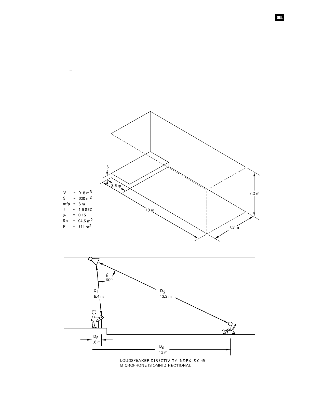
Calculations for a Medium-Size Room
Consider a more typical (and more
complicated) situation in which the sound system is
used in a larger room and in which a directional
microphone is employed. Figures 6-4 and 6-5 show a
room having a volume of 918 m3, a total surface area
of 630 m
and we would do well to examine the actual
distribution of absorptive material in the room.
Chapter 5 explains why the effective room constant
R’ in a particular situation may vary substantially from
2
and a = 0.15.
The first step is to calculate the room constant,
the figure given by the equation R = Sa/(1 -a).
Rather than complicate the example, however,
assume that the equation really does work and that
2
the room constant is about 110 m
.
The next step is to calculate critical distances
for the talker and the loudspeaker. Since the
loudspeaker does not have a uniform radiation
pattern, we must calculate its critical distance at the
particular angle in which we are interested. Figure
6-5 shows the distances involved and the
geometrical relationships between talker,
microphone, loudspeaker and listener.
Figure 6-4. A sound system in a medium-size room
Figure 6-5. Sound system in a medium-size room, gain calculations
6-5
Sound System Design Reference Manual
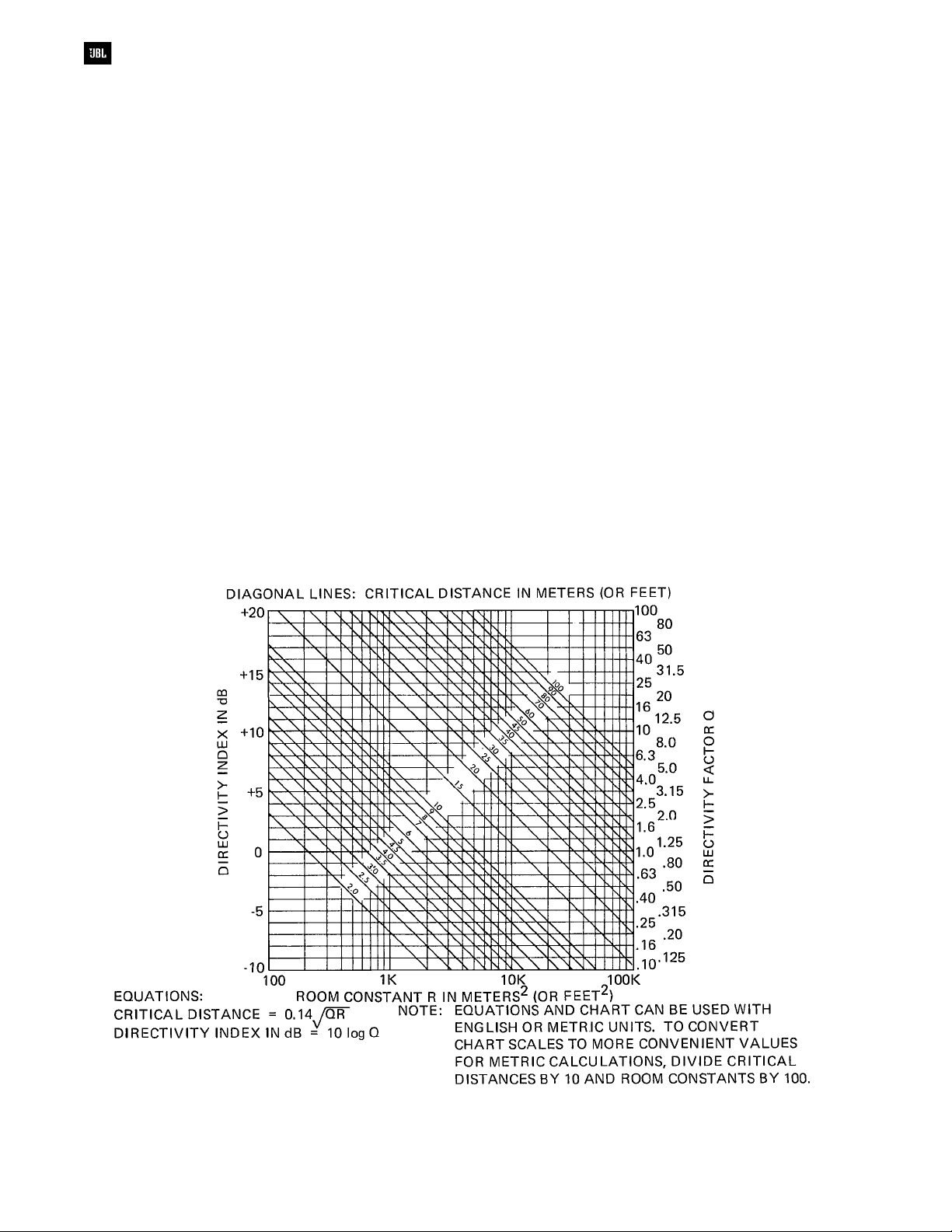
In the frequency range of interest, the
loudspeaker is assumed to have a directivity index
along its primary axis of 9 dB. From Figure 6-6 we
find the corresponding critical distance of 4.2 meters.
The loudspeaker’s directivity index at a vertical angle
of 60° is assumed to be -3 dB, with a corresponding
critical distance of 1 meter. The unaided talker has a
directivity index of 3 dB and his critical distance must
therefore be 2 meters.
Our next step in calculating system gain is to
find the difference in level produced by an unaided
talker at the listener position as contrasted with that
at the microphone position. In this example the
listener is 12 meters from the talker and the
microphone again is .6 meters away.
The talker’s critical distance of 2 meters is more
than 3 times the microphone distance. Therefore, the
microphone is well in the direct field of the talker. The
listener is more than 3 times the critical distance and
is well into the reverberant field of the unaided talker.
Setting the level produced by the unaided talker at
70 dB for a distance of .6 meters, we calculate that
the direct field at D
must be 60 dB, and since the
C
reverberant field must also equal 60 dB, the level
produced by the unaided talker at the listener’s
position is 60 dB.
The third step is to make similar calculations for
the loudspeaker alone. The listener is located on the
major axis of the loudspeaker and is more than 3
times the critical distance of 4.2 meters. The
microphone is located at a vertical angle of 60
degrees from the loudspeaker’s major axis, and also
is more than 3 times the critical distance (at this
angle) of 1 meter. Both the listener and the
microphone are located in the reverberant field of the
loudspeaker.
If the sound level produced by the loudspeaker
at the microphone can be no greater than 70 dB (the
same level as the talker) then the level produced by
the loudspeaker at the listener’s position must also
be 70 dB, since both are in the reverberant field.
Having established these relationships we
know that the talker produces a level at the listener’s
position of 60 dB with the sound system off and 70
dB with the sound system on, or a maximum
potential gain of 10 dB. Allowing 6 dB headroom in a
properly equalized system, we still realize 4 dB gain
at the listener’s position, and the sound system can
be said to provide a small but perceptible increase in
sound level.
6-6
Figure 6-6. Critical distance as a function of room
constant and directivity index or directivity factor

Sound System Design Reference Manual
However, all of the preceding calculations have
assumed that the microphone is an omnidirectional
unit. What happens if we substitute a directional
microphone? Figure 6-7 shows the additional
geometrical relationships needed to calculate the
increase in gain produced by a directional
microphone.
Note that the distance from talker to
microphone is still .6 meters and that the talker is
assumed to be located along the major axis of the
microphone. The loudspeaker is located 5.4 meters
from the microphone along an angle of 75° from the
major axis.
Figure 6-7 also shows a typical cardioid pattern
for a directional microphone. The directivity index of
such a microphone along its major axis is about 5 dB.
Since the talker is located on the major axis of
the microphone, it “hears” his signal 5 dB louder than
the random incidence reverberant field. In theory this
should increase potential system gain by a factor of
5 dB.
But we must also consider the microphone’s
directional characteristics with relation to the
loudspeaker. If the directivity index of the microphone
at 0° is 5 dB, the polar pattern indicates that its
directivity index at 75° must be about 3 dB. This tells
us that even though the loudspeaker is 75° off the
major axis of the microphone, it still provides 3 dB of
discrimination in favor of the direct sound from the
loudspeaker.
We know that the loudspeaker’s directivity
index is -3 dB along the axis between the
loudspeaker and the microphone. We also know that
the microphone’s directivity index along this axis is
+3 dB. The combined directivity indices along this
axis must therefore, be 0 dB and we can find the
equivalent critical distance from Figure 6-6.
The combined critical distance of loudspeaker
and microphone along their common axis is about
1.3 meters. Since the distance between the two is
more than 3 times this figure, the microphone still lies
within the reverberant field of the loudspeaker. Using
the directional microphone should therefore allow an
increase in potential system gain before feedback of
about 5 dB. (In practice, little more than 3 or 4 dB of
additional gain can be achieved.)
Figure 6-7. Characteristics of a cardioid microphone
6-7

Sound System Design Reference Manual
Calculations for a Distributed
Loudspeaker System
Figure 6-8 shows a moderate-size meeting
room or lecture room. Its volume is 485 m3, surface
area is about 440 m2, and a is 0.2 when the room is
empty. For an unaided talker in the empty room, R is
2
110 m
increases to 0.4 and the corresponding room
constant is 293 m2. We calculate the critical distance
for the unaided talker (directivity index of 3 dB) to be
2 meters in an empty room and 3.4 meters when the
room is full.
diagrammed in Figure 6-9. Forty loudspeakers are
mounted in the ceiling on 1.5 meter centers to give
smooth pattern overlap up into the 4 kHz region.
Coverage at ear level varies only 2 or 3 dB through
the entire floor area.
. However, when the room is fully occupied, a
The room is provided with a sound system
The usual definitions of critical distance and
direct-to-reverberant ratio are ambiguous for this kind
of loudspeaker array. Here, however, we are
interested only in potential acoustic gain, and the
ambiguities can be ignored. We already have stated
that the loudspeaker array lays down a uniform
blanket of sound across the room. The relative
directional and temporal components of the sound
field do not enter into gain calculations.
An omnidirectional microphone is located
.6 meters from the talker, less than 1/3 DC. No matter
how many people are present, the microphone is in
the direct field of the talker.
The farthest listener is 9 meters from the talker,
more than three times DC when the room is empty,
and just about three times DC when the room is full.
If the unaided talker produces 70 dB sound
level at the microphone with the system off, and if the
amplified sound level can be no greater than 70 dB
at the microphone with the system on, then the
maximum level is 70 dB everywhere in the room
.
6-8
Figure 6-8. A moderate-size lecture room
Figure 6-9. Sound system in a medium-size lecture room

Sound System Design Reference Manual
From our calculations of critical distances, we
see that the unaided talker will produce a sound level
at the listener of 59 dB in an empty room and about
55 dB with a full audience. For a usable working
delta of -6 dB, the calculated acoustic gain at the
listener’s position is about 5 dB in an empty room
and about 9 dB when full.
Can we get more gain by turning off the
loudspeaker directly over the microphone? Not in a
densely packed array such as this. The loudspeakers
are mounted close together to produce a uniform
sound field at ear level. As a result, the contribution
of any one loudspeaker is relatively small. However,
by turning off all the loudspeakers in the performing
area and covering only the audience, some increase
in system gain may be realized.
In the example just given, each loudspeaker is
assumed to have a directivity index in the speech
frequency region of +6 dB at 0°, +3 dB at 45°, and
0 dB at 60°. Suppose we use only the 25
loudspeakers over the audience and turn off the 15
loudspeakers in the front of the room. In theory, the
increase in potential gain is only 1 dB with a single
listener or 2 dB when the audience area is filled.
Even if we allow for the probability that most of the
direct sound will be absorbed by the audience, it is
unlikely that the gain increase will be more than 3 dB.
The calculations required to arrive at these
conclusions are tedious but not difficult. The relative
direct sound contribution from each of the
loudspeakers at microphone and listener locations is
calculated from knowledge of polar patterns and
distances. By setting an arbitrary acoustic output per
loudspeaker, it is then possible to estimate the sound
level produced throughout the room by generally
reflected sound (reverberant field) and that produced
by reflected plus quasi-direct sound.
System Gain vs. Frequency Response
In the preceding examples we have not defined
the frequency range in which gain calculations are to
be made. In most sound systems the main reason for
worrying about system gain is to make sure that the
voice of a person talking can be amplified sufficiently
to reach a comfortable listening level in all parts of
the seating area. Therefore, the most important
frequency band for calculating gain is that which
contributes primarily to speech intelligibility: the
region between 500 and 4000 Hz.
Below 500 Hz the response of the system can
be gradually shelved, or attenuated, without seriously
degrading the quality of speech. Above 4 kHz sound
systems tend to take care of themselves, due to the
increase in overall acoustical sound absorption. At
very high frequencies, most environments are
substantially absorptive, the air itself contributes
considerable acoustical absorption and loudspeaker
systems tend to become directional. These factors
make it highly unusual to encounter feedback
frequencies much above 2500 Hz.
To make sure that a sound reinforcement
system will successfully amplify speech, it is a good
idea to make gain calculations in at least two
frequency bands. In a well-designed system, if
calculations are made for the regions centered at 1
kHz and 4 kHz, chances are that no unforeseen
problems in achieving desired system gain will be
encountered.
However, the region below 500 Hz cannot
simply be ignored. The room constant and the
directivities of the loudspeaker system and the
microphone should be checked in the 200 - 500 Hz
range to make sure that there are not substantial
deviations from the calculations made at 1 and 4
kHz. If the room has very little absorption below 1
kHz, and if the loudspeaker system becomes
nondirectional in this region, it may be impossible to
achieve satisfactory system gain without severely
attenuating the mid-bass region. The result is the all
too familiar system which provides satisfactory
speech intelligibility, but which sounds like an
amplified telephone.
The Indoor Gain Equation
From the foregoing discussions, we can
appreciate the complexity of indoor system gain
analysis and the need for accurately calculating the
attenuation of sound along a given path, from either
talker or loudspeaker, noting when we leave the
direct field and make the transition into the
reverberant field. If we were to attempt to establish a
general system gain equation, we would have a very
difficult task. However, in the special case where the
microphone is in the talker’s direct field, and both
microphone and listener are in the loudspeaker’s
reverberant field, then the system gain equation
simplifies considerably.
Let us consider such an indoor system, first
with the system turned off, as shown in Figure 6-10.
If the talker produces a level L at the microphone,
then the level produced at the listener will be:
6-9

Sound System Design Reference Manual
Level at listener = L - 20 log (Dct/Ds), where D
ct
is the critical distance of the talker. The assumption
made here is that the level at the listener is entirely
made up of the talker’s reverberant field and that that
level will be equal to the inverse square component
at Dct.
Now, the system is turned on, and the gain is
advanced until the loudspeaker produces a level L at
the microphone. At the same time, the loudspeaker
will produce the same level L at the listener, since
both microphone and listener are in the
loudspeaker’s reverberant field.
Subtracting the levels at the listener between
the system on and the system off, we have:
Difference = L -
[L - 20 log (D
ct/Ds
)]
or:
Gain = 20 log Dct - log D
s
Finally, adding a 6 dB safety factor:
Gain = 20 log Dct - 20 log Ds - 6
Note that there is only one variable, Ds, in this
equation; Dct is more or less fixed by the directivity of
the talker and the acoustical properties of the room.
Of course there are many systems in which the
microphone may be placed in the transition zone
between the talker’s direct and reverberant fields, or
where the listener is located in the transition region
between the loudspeaker’s direct and reverberant
fields. In these more complicated cases, the
foregoing equation does not apply, and the designer
must analyze the system, both on and off, pretty
much as we went stepwise through the three
examples at the start of this chapter.
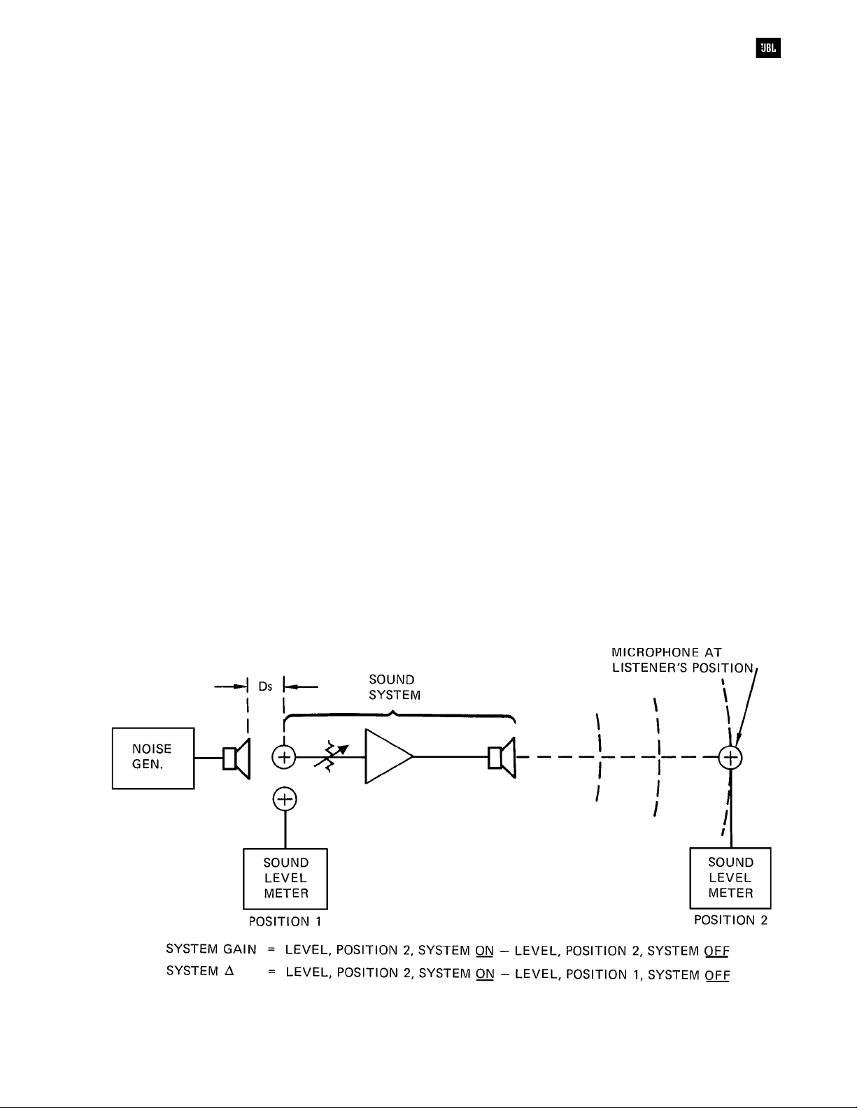
Measuring Sound System Gain
Measuring the gain of a sound system in the
field is usually done over a single band of
frequencies. It is normally specified that system gain
shall be measured over the octave-wide band
centered at 1 kHz. Another common technique is to
use pink noise which is then measured with the
A-weighted scale. A typical specification for sound
system gain might read as follows:
“The lectern microphone shall be used in its
normal position. A small loudspeaker shall be
mounted on a stand to simulate a person talking
approximately .6 meters from the microphone. The
response of this test loudspeaker shall be reasonably
flat over the range from 250 - 4000 Hz.
“With the system turned off, the test
loudspeaker shall be driven with a pink noise signal
to produce a sound level of about 80 dB(A) at the
system microphone. This level shall be measured
with a precision sound level meter, using the “A”
scale, with its microphone immediately adjacent to
the sound system microphone.
“After noting the sound level at the system
microphone with the sound system turned off, the
sound system shall be turned on and its gain advanced to
a point just below sustained oscillation. The amplified
sound level shall be measured with the same sound
level meter in the central part of the auditorium.
“The D of the sound system shall be calculated
by subtracting the measured SPL at the microphone
(system off) from the measured SPL in the auditorium
(system on).”
The gain of the system is of course measured at
some point in the auditorium and is the level difference
at that point produced by the test loudspeaker before
and after the system has been turned on. Details of the
measurements are shown in Figure 6-11.
6-10
Figure 6-10. Conditions for the indoor system gain equation
Sound System Design Reference Manual
General Requirements for Speech
Intelligibility
The requirements for speech intelligibility are
basically the same for unamplified as for amplified
speech. The most important factors are:
1. Speech level versus ambient noise level.
Every effort should be made to minimize noise due to
air handling systems and outside interferences. In
general, the noise level should be 25 dB or greater
below the lowest speech levels which are expected.
However, for quite high levels of reinforced speech,
as may be encountered outdoors, a noise level 10 to
15 dB below speech levels may be tolerated.
2. Reverberation time. Speech syllables occur
three or four times per second. For reverberation
times of 1.5 seconds or less, the effect of reverberant
overhang on the clarity of speech will be minimal.
3. Direct-to-reverberant ratio. For reverberation
times in excess of 1.5 seconds, the clarity of speech
is a function of both reverberation time and the ratio
of direct-to-reverberant sound.
In an important paper (8), Peutz set forth a
method of estimating speech intelligibility which has
found considerable application in sound system
design. The Peutz findings were compiled on the
basis of data gathered over a period of years. The
data and the method used to arrive at the published
conclusion are clearly set forth in the paper itself.
The conclusions can be summarized as follows:
1. In practice, the articulation loss of
consonants can be used as a single indicator of
intelligibility. Although the original research of Peutz
was in Dutch speech, the findings seem to be equally
applicable to English.
2. As would be expected, the researchers found
wide variations in both talkers and listeners.
However, a 15% articulation loss of consonants
seems to be the maximum allowable for acceptable
speech intelligibility. In other words, if articulation loss
of consonants exceeds 15% for the majority of
listeners, most of those people will find the
intelligibility of speech to be unacceptable.
3. Articulation loss of consonants can be
estimated for typical rooms. Articulation loss of
consonants is a function of reverberation time and
the direct-to-reverberant sound ratio.
4. As a listener moves farther from a talker
(decreasing the direct-to-reverberant sound ratio)
articulation loss of consonants increases. That is,
intelligibility becomes less as the direct-toreverberant ratio decreases. However, this
relationship is maintained only to a certain distance,
beyond which no further change takes place. The
boundary corresponds to a direct-to-reverberant ratio
of -10 dB.
Figure 6-1 1. Measurement of sound system gain and delta (
DD
D)
DD
6-11

Sound System Design Reference Manual
The last point is illustrated graphically in Figure
6-12, adapted from the Peutz paper. Each of the
diagonal lines corresponds to a particular
reverberation time. Each shelves at a point
corresponding to a direct-to-reverberant sound ratio
of -10 dB. Note that the shelf may lie above or below
the 15% figure depending upon the reverberation
time of the room. This agrees with other published
information on intelligibility. For example, Rettinger
points out that in rooms having a reverberation time
of 1.25 seconds or less, direct sound and early
reflections always make up the greater portion of the
total sound field. Intelligibility in such rooms is good
regardless of the direct-to-reverberant sound ratio at
any given listening position. Conversely, anyone who
has worked in extremely large reverberant spaces
such as swimming pools or gymnasiums knows that
intelligibility deteriorates rapidly at any point much
beyond the critical distance. According to the chart, a
15% articulation loss of consonants in a room having
a reverberation time of 5 seconds corresponds to a
direct-to-reverberant sound ratio of only - 5.5 dB.
Problems associated with speech intelligibility
in enclosed spaces have received a great deal of
attention prior to the publication of the Peutz paper.
The virtue of Peutz’ method for estimating speech
intelligibility is its simplicity. It must be remembered,
however, that a number of contributing factors are
ignored in this one simple calculation. The chart
assumes that satisfactory loudness can be achieved
and that there is no problem with interference from
ambient noise. It also postulates a single source of
sound and a well behaved, diffuse reverberant sound
field.
The data from the Peutz paper have been
recharted in a form more convenient for the sound
contractor in Figure 6-13. Here we have arbitrarily
labeled the estimated intelligibility of a talker or a
sound system as “satisfactory”, “good”, or “excellent”,
depending upon the calculated articulation loss of
consonants.
There often is a dramatic difference in the
acoustical properties of a room depending upon the
size of the audience. Calculations should be made
on the basis of the “worst case” condition. In some
highly reverberant churches particularly, it may turn
out that there is no practical way to achieve good
intelligibility through the entire seating area when the
church is almost empty. The solution may involve
acoustical treatment to lessen the difference between
a full and an empty church, or it may involve a fairly
sophisticated sound system design in which
reinforced sound is delivered only to the forward
pews when the congregation is small (presuming that
a small congregation can be coaxed into the forward
pews).
6-12
Figure 6-12. Probable articulation loss of consonants vs.
reverberation time & direct-to-reverberant sound ratio

Sound System Design Reference Manual
Also, local acoustical conditions may exist
which are not taken into account by statistical theory
and, therefore, not covered by the Peutz findings or
any of the other equations we have studied. Such
localized dead spots or zones of interference may
not be discovered until the sound system is installed.
In large reverberant spaces, sufficient flexibility
should always be built into the sound system design
to allow for such surprises.
The effect of masking by unwanted background
noise has been touched on only briefly in this
section. Such unwanted noise may be produced by
sound from the outside environment, by noisy air
handling equipment, by noisy backstage mechanical
equipment or by the audience itself. For good
listening conditions, the level of ambient noise as
measured on the “A” scale should be at least 10 dB
below the desired signal. Since the optimum level for
reproduced speech in the absence of strong
background noise is 65 - 70 dB(A) this means that
background noise with a full audience should not
exceed 55 dB(A). In auditoriums and concert halls,
acoustical designers normally attempt to reduce
background noise in an empty house to a level not
exceeding 25 dB(A). In a church or meeting hall, the
maximum tolerable background noise for an empty
room is about 40 dB(A).
A sound reinforcement system cannot be
turned up indefinitely. In many situations it is difficult
enough to achieve a useful operating level of 60 - 65
dB(A) without feedback. It is easy to see, therefore,
that the presence of excessive background noise can
render an otherwise good sound reinforcement
system unsatisfactory.
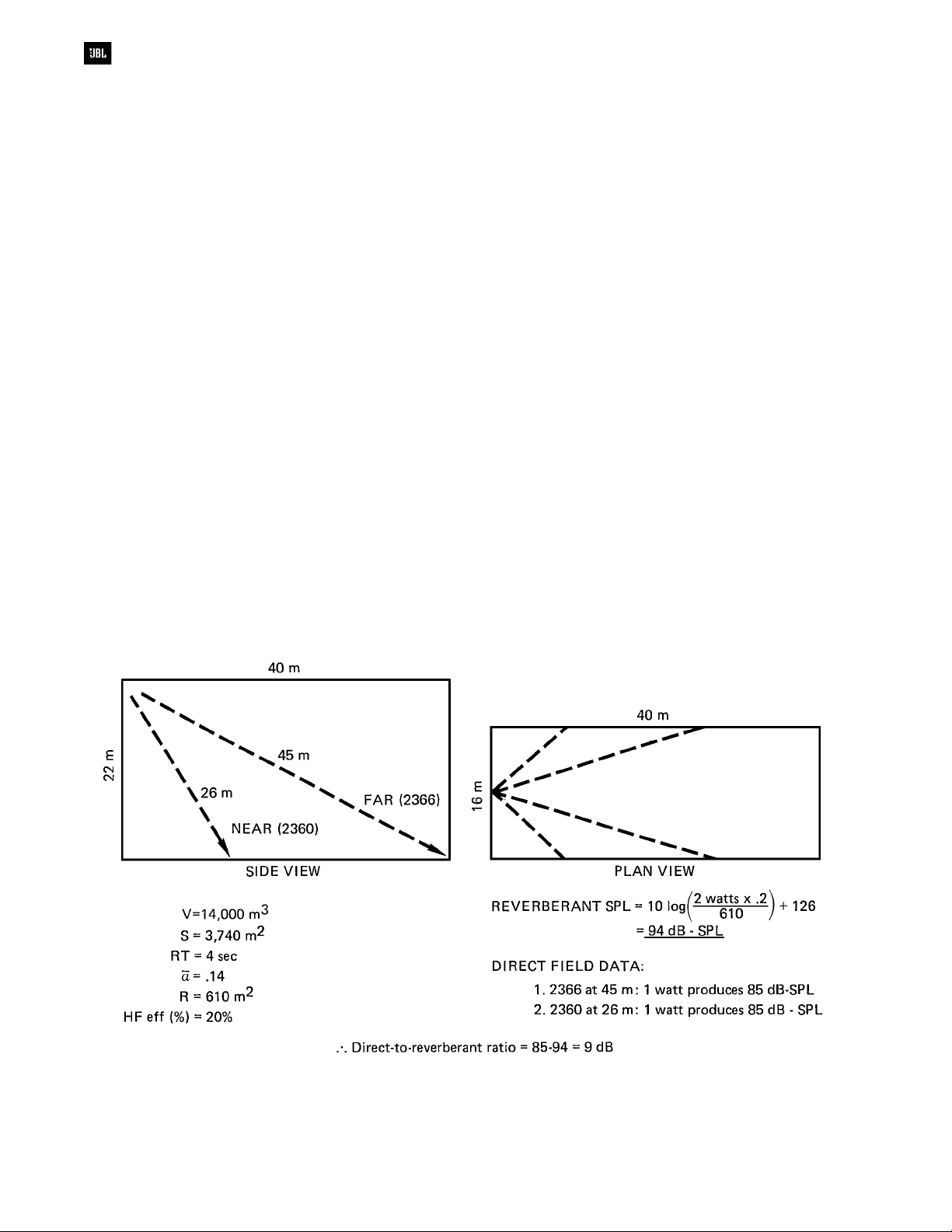
As an example of how the Peutz analysis can
dictate the type of sound system to be used, let us
consider a reinforcement system to be used in a large
reverberant church. Details are shown in Figure 6-14.
Let us assume that the reverberation time is 4
seconds at mid-frequencies and that the designer’s
first choice is a single-point loudspeaker array to be
placed high above the chancel. Coverage
requirements pretty much dictate the directional
characteristics of the array, and let us assume that
the array will consist of two JBL Bi-Radial horns: 20°
by 40° for far coverage, and 90° by 40° for near
coverage. What we wish to calculate is the direct-toreverberant ratio at selected points in the audience
area to determine if the Peutz criteria for acceptable
intelligibility can be met. The most direct way of doing
this is to calculate the total reverberant level in the
room for a given power input to each horn and
compare it with the direct sound coverage provided
by each horn over its coverage angle.
Figure 6-13. Probable intelligibility as a function of reverberation time
and direct-to-reverberant sound ratio
6-13
Sound System Design Reference Manual
The analysis shown in Figure 6-14 indicates
that when each of the two horns is powered by one
watt, the reverberant field in the room (read directly
from Figure 5-21) is 94 dB-SPL. The direct field level
provided by each horn over its coverage angle is
about 85 dB-SPL. This produces a direct-toreverberant ratio of -9 dB, and an inspection of
Figure 6-13 tells us that the system will have
marginal intelligibility. Note that for 4 seconds of
reverberation time, the direct-to-reverberant ratio
should be no less than about -7 dB if acceptable
intelligibility is to be expected. This simple analysis
has told us that, on paper, we have designed a
sound system which will likely fail to satisfy the
customer.
Had the system consisted of a single horn,
knowledge of its on-axis DI and Q could have led
quickly to a determination of critical distance, and the
direct-to-reverberant ratio could have been scaled
from D
. However, for the composite array analyzed
C
here, there is no single value of DI or Q which can be
used, and a direct calculation of the overall
reverberant level, using what we know about the
efficiency of the transducers, and making a
comparison with the direct field, based on the
sensitivities of the transducers, is the quickest way to
solve the problem.
But the question remains: What kind of system
will work in this large resonant room? Clearly, a
distributed system is called for. In such a system, a
number of lower-powered loudspeakers are placed
on columns on each side of the church, each
loudspeaker covering a distance of perhaps no more
than 5 or 6 meters. In this way, the direct-toreverberant ratio can be kept high. If such a system
is further zoned into appropriate time delays, the
effect will be quite natural, with subjective source
localization remaining toward the front of the listening
space. Details of this are shown in Figure 6-15.
Again, we calculate the total reverberant level
and compare it with the longest throw each
loudspeaker will be called upon to handle. There are
14 loudspeakers, 7 on each side. Let us assume that
the efficiency of these loudspeakers is 1.2% and that
their sensitivity is 95 dB, 1 watt at 1 meter. Feeding
one watt into each loudspeaker results in a total
acoustical power of 14 x .012, or 0.17 watt. Again
using Figure 5-21, we observe that the reverberant
level will be 92 dB-SPL. The longest throw each
loudspeaker has to cover is, say, 4 meters. Since the
1-watt, 1-meter sensitivity is 95 dB, the direct field for
each loudspeaker will be 12 dB lower, or 83 dB.
6-14
Figure 6-14. Analysis of intelligibility criteria
 Loading...