

Page 1
JBL PERFORMANCE™SERIES
P81
P941
HIGH-PERFORMANCE
IN-WALL LOUDSPEAKERS
OWNER’S GUIDE
Page 2

81/P941 IN-WALL
P
OUDSPEAKERS
L
OCUMENTATION
D
ONVENTIONS
C
3 Documentation Conventions
Introduction
4
4 Highlights
4 Product Registration
Unpacking
5
6 Loudspeaker Overview
6 Driver Complement
7 Filter Network
Input Panel
7
8 Installation Considerations
8 Loudspeaker Placement
Installation Instructions
9
11 Making Connections
12 Optimizing Performance
13 Loudspeaker Volume
14 Specifications
14 Dimensions
14 Obtaining Service
15 Index
This document contains general safety,
nstallation, and operation instructions
i
or the JBL
f
®
erformance
P
™
eries P81
S
and P941 In-Wall Loudspeakers. It is
important to read this document before
attempting to use your loudspeakers.
ay particular attention to safety
P
instructions.
WARNING
Calls attention to a procedure, practice,
ondition, or the like that, if not correctly
c
performed or adhered to, could result
in injury or death.
CAUTION
Calls attention to a procedure, practice,
condition, or the like that, if not correctly
performed or adhered to, could result
in damage to or destruction of part or
all of the product.
NOTE
Calls attention to information that is
essential to highlight.
®
3
Page 3

NTRODUCTION
I
Thank you for purchasing the JBL
erformance Series P81/P941 In-Wall
P
oudspeakers. Designed for discerning
L
audiophiles, the P81 and P941 offer versatile, easily integrated in-wall loudspeakers that provide the superior,
ncolored sound that is the hallmark of
u
JBL loudspeakers. The P81 and P941
reproduce realistic, accurate signals
with minimal coloration and distortion,
making them perfect complements to
BL Performance front speakers in
J
multichannel setups. Proprietary transducers, sophisticated filter networks,
and user-adjustable compensation controls allow the P81/P941 to achieve
remarkable sound quality and performance befitting the most demanding
home entertainment systems.
The P81 and P941 are also perfectly
suited as front and surround speakers
in complete in-wall setups, or as stereo
pairs in secondary listening spaces, or
for integration with flat-screen television home theater installations. Unlike
freestanding loudspeakers, the P81 and
P941 speakers occupy no space in living areas and will not detract from the
décor of the listening room. They are
easily mounted in either pre-existing or
new construction projects.
A critical aspect of loudspeaker design,
transducers convert electrical signals
into audible sounds, profoundly affecting
speaker performance. Combining superior form and function, the P81 and P941
transducers feature a distinctive design
that allows for smoother frequency
response. The cones are constructed
with Organic Ceramic Composite cone
material to reduce dis
spiders are constructed
®
Nomex
blend with optimized geometry
tortion, while the
of a high-strength
for increased linearity.
A two-way design, the P81 transducers
effectively cover a broad range of frequencies. A 7-1/2-inch (191mm) woofer
delivers highly refined and dynamically
authoritative low frequencies down to
the very lowest octaves. Also, a 1-inch
(25mm) titanium-dome tweeter repro
duces high frequencies well above
audible levels, with wide dispersion for
open, airy treble.
A three-way design, the P941, in addi
tion to its 9-inch (229mm) woofer and
1-inch (25mm) tweeter
, also features
a 3-1/2-inch (89mm) midrange, which
handles critical mid-band frequencies
ith natural tonal balance over a wide
w
perating range.
o
An advanced midrange (P941 only)
motor structure includes two high-
rade neodymium magnets placed
g
t the center of the motor structure,
a
inside the voice coil, for improved
magnetic shielding. Inside the motor, a
black-plated steel-shield cup facilitates
eat dissipation for higher power han-
h
dling. An integrated aluminum fluxstabilization ring minimizes modulation
inside the motor’s static gap flux field,
reatly reducing distortion. A copper ring
g
inside the motor’s gap reduces distortion
even further. Both rings are optimally
sized and placed to maintain constant
linear voice coil inductance with
forward and backward motions.
The P81 has a high-order filter at
2.8kHz. In the P941, high-order filters at
300Hz and 2kHz optimize loudspeaker
on- and off-axis response, helping
to ensure smooth octave-to-octave
balance and timbral accuracy. The P81
and P941 feature gold-plated binding
posts that accommodate two connection methods, while separate HighFrequency Tilt, Low-Frequency Boundary
Compensation, High-Frequency Level
and Listener Axis controls compensate
for less-than-ideal listening room
acoustics and loudspeaker placement.
For more than 50 years, JBL has stood
at the forefront of loudspeaker design.
With extensive research and design
facilities, the JBL Performance Series
P81 and P941 loudspeakers benefit
from cutting-edge tools such as a multichannel listening lab for double-blind
listening tests; a laser interferometer
for detailed driver analysis; real ane
choic chambers for precise tests and
measurements; finite element analysis
for advanced loudspeaker modeling;
and a stereo lithography apparatus for
design verification.
Adding to the proud lineage of JBL’s
Performance Series loudspeakers, the
P81 and P941 further advance JBL
’s
reputation as the leading designer
and manufacturer of high-quality,
high-performance loudspeakers.
P81/P941 HIGHLIGHTS
n Exceptional accuracy
n Proprietary 7-1/2-inch (191mm)/9-inch
229mm) Organic Ceramic Composite
(
woofer
n Proprietary 3-1/2-inch (89mm)
rganic Ceramic Composite
O
midrange (P941 only)
roprietary 1-inch (25mm) titanium-
n P
dome tweeter
n High output with low distortion
n Gold-plated binding posts
igh-Frequency Level control
n H
n High-Frequency Tilt control
n Low-Frequency Boundary
Compensation control
n Listener Axis control
n Advanced woofer and midrange
(P941 only) motor structure
n Large voice coils for wide dynamic
range without compression
n Wall-mounting frame which features
spring-loaded clamps to securely
anchor loudspeaker into wall opening
n Optional rough-in bracket for stud-
mounting prior to drywall installation
(not included)
PRODUCT REGISTRA
Please register the P81/P941 as soon
as possible after purchase. To do so,
register online at www.jbl.com. The
product registration serves no warranty
purposes. Retain the original, dated
sales receipt as proof of warranty
coverage.
TION
4
Page 4
NPACKING
Top Pad
Bottom Pad
Frame
Alignment Tool
Paint Mask
Protective
Cloth
Grille
Allen Keys/Spacer Shim
Fiberglass
Insulation
Wall Template
Replacement
Scrim Cloth
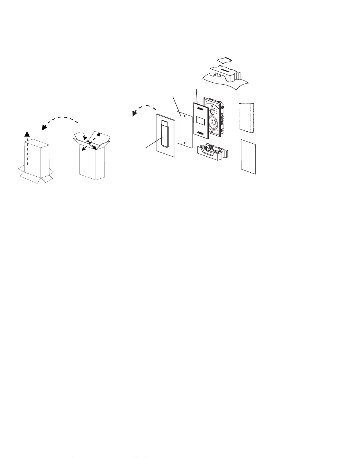
Figure 2: Packing Materials
F
igure 1: Unpacking the P81/P941
¡
™
£
U
The P81 and P941 require special care
nd handling during unpacking. Pay
a
articular attention to the precautions
p
that appear in this section and to other
precautions that appear throughout this
owner’s manual.
hen unpacking, save all packing
W
materials for possible future shipping
needs. Refer to the Obtaining Service
section on page 14 for additional
nformation.
i
Figure 1: Unpacking the P81/P941
Figure 2: Packing Materials
To Unpack the P81 and P941:
1. Place the packing carton in the
upright position and fully open the top
flaps, as shown in Step 1 of Figure 1.
2. Without allowing the top flaps to
close, move the outer packing carton
into an inverted position, as shown in
Step 2 of Figure 1.
3. Lift the packing carton off of the
loudspeaker, as shown in Step 3
of Figure 1. Use caution to avoid
damaging the loudspeaker or frame
clamps. At this point, the loudspeaker
will be upside-down.
4. Remove the bottom pad, and then
remove the frame alignment tool
and grille from the grille filler
items are identified in Figure 2.
5. Set aside the wall template, paint
mask, fiberglass insulation, spacer
shim, replacement scrim cloth and
Allen keys.
6. Invert speaker so it is in the upright
position.
When the P81/P941 is in the upright
7.
position, remove the top pad.
8. Leave the loudspeaker upright in the
bottom pad until ready to install.
. These
5
Page 5
OUDSPEAKER OVERVIEW
¡
™
£
¢
∞
§
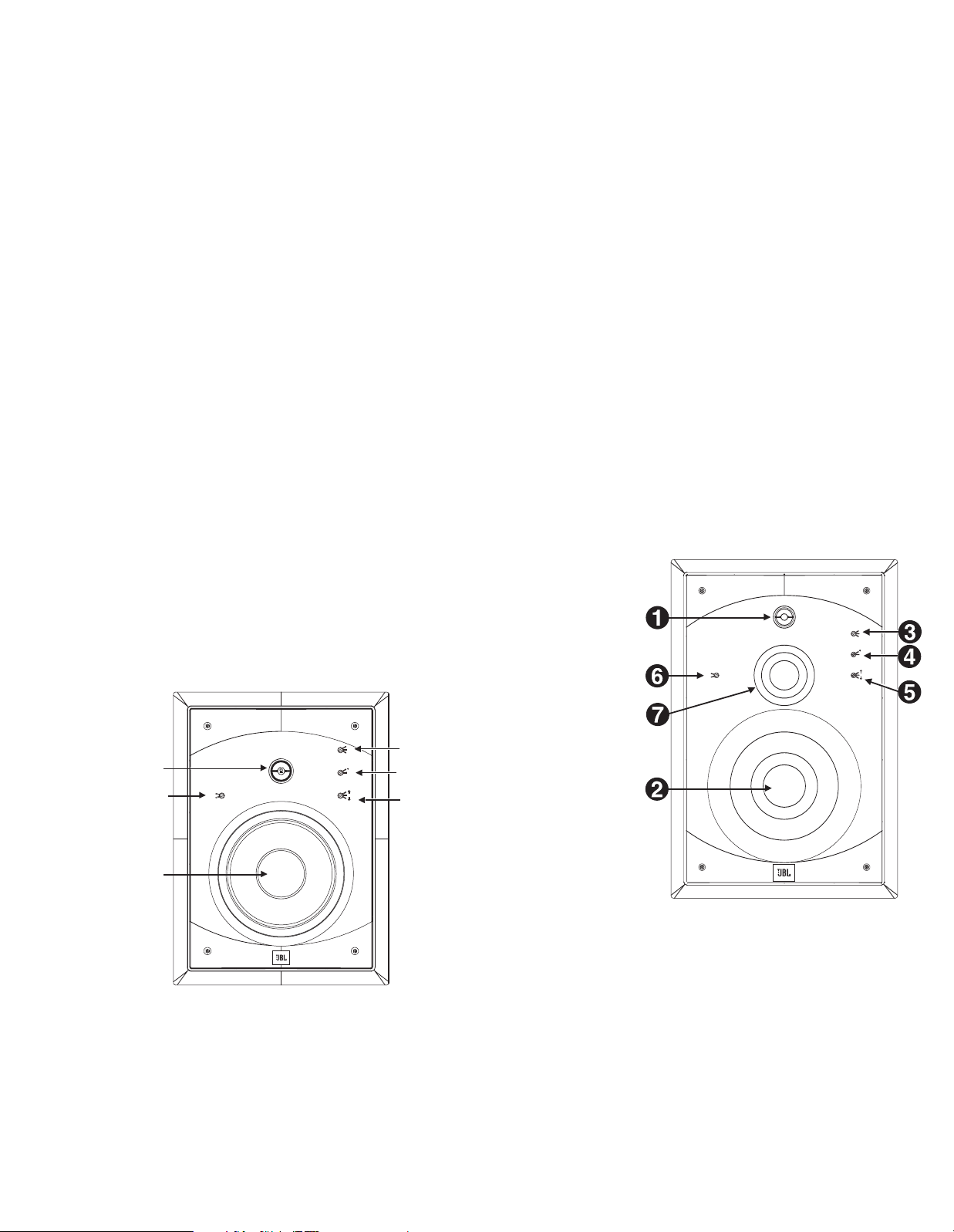
Figure 3: P81 Speaker (Front View)
on
off
Low Frequency
Boundary
Compensation
High Frequency Level (dB)
Listener Axis
High Frequency Tilt
on axis
0
+1
0
–1
Figure 4: P941 Speaker (Front View)
on
o
ff
Low Frequency
Boundary
Compensation
High Frequency Level (dB)
L
istener Axis
H
igh Frequency Tilt
o
n axis
0
+1
0
–1
L
P81/P941 DRIVER COMPLEMENT
he numbers in Figure 3 correspond to
T
the numbered items in this section.
1. Tweeter
1-inch (25mm) titanium dome
•
Underhung with copper-clad alu-
•
minum wire for low distortion
Ferrofluid for high-power handling
•
with reduced compression
2. Woofer
7-1/2-inch (191mm)/9-inch (229mm)
•
cones constructed with Organic
Ceramic Composite cone material for
low distortion
rue pistonic operation for increased
T
•
freedom from coloration
Symmetrical Field Geometry (SFG™)
•
design for low overall distortion
Aluminum ring for flux stabilization
•
greatly reduces distortion at low frequencies
Butyl rubber surround for large, linear
•
excursion capabilities
Carbon composite aluminum (CCA)
•
flatwire voice coil wound on a 1-1/2inch (38mm) fiberglass bobbin for low
mass and higher power handling
Vented center pole for improved heat
•
dissipation and low compression
The numbers in Figure 3 correspond to the
numbered items in the Driver Complement
section.
Figure 3: P81 Speaker (Front View)
6
3. High-Frequency Level (dB) Control
rovides a shift in the output level of
P
the tweeter or overall high-frequency
response (active above approximately
2.5kHz). The options are –1dB, 0dB
nd +1dB.
a
4. High-Frequency Tilt Control
Adds a ”tilt“ to the high-frequency
esponse. The tilt will become active
r
above approximately 8kHz (depart
from nominally flat response) and will
increase to 3dB – 4dB at 20kHz. This
will offer an improved high-frequency
response for installations where the
primary listening position is located
significantly off the tweeter axis (for an
effect almost like adding ”toe in“ towards
the listening position). The added
highfrequency contour helps to offset perceived reduction of high-frequency
response for off-axis listeners due to
the increase in directivity of the system
(tweeter beaming) above 8kHz.
5. Listener Axis Control
inverted speaker installations. Refer to
he Notes on page 9 and the Optimizing
t
erformance (page 12) section for addi-
P
tional information.
6. Low-Frequency Boundary
ompensation Control
C
Compensates for less-than-ideal
speaker placement near adjacent walls
or boundaries.
Select the “off” setting if the speaker
•
is mounted at least 4 feet away from
adjacent walls or boundaries.
elect the “on” position if the
S
•
speaker is less than 4 feet from one
(or possibly two) or more adjacent
walls or boundaries. In the ”on“
position, system output is reduced
below approximately 400Hz to offset
the increased low-frequency support,
due to the boundary.
NOTE: Refer to the Optimizing
Performance section on page 12 for
more information about the front-panel
controls.
All loudspeakers sound best when the
listener is positioned at optimal angles
relative to the speaker placement. This
is a fixed angle for most loudspeakers,
but the P81 and P941 provide compensation for much greater placement
flexibility. The listener axis control,
used in conjunction with the placement
of the speaker, can obtain excellent
results in a very wide range of circumstances. This control optimizes system
response for installations in which the
listening positions are lower than,
higher than, or directly level with the
tweeter. This switch will be active
in the network transition regions
between the woofer and tweeter
(in the P81) and the midrange and
tweeter (in the P941).
Select the “high” (up arrow) setting
•
if the speaker is mounted so that the
listener is at tweeter level or above.
Select the “on axis” setting if the
•
listener position is located directly
on axis with the tweeter level.
Select the “low” (down arrow) set-
•
ting if the speaker is mounted so that
the listener is below tweeter level.
NOTE: In some circumstances, such
as when the speaker is to be mounted
high on the wall towards the ceiling, it
may be desired to invert the speaker in
order to place the tweeter axis closer
to the listener’s ear level. The Listener
Axis Control will also optimize these
The numbers in Figure 4 correspond to the
numbered items in the Driver Complement
section.
Figure 4: P941 Speaker (Front View)
7. Midrange (P941 Only)
3-1/2-inch (89mm) cone constructed
•
with Organic Ceramic Composite
material
Die-cast basket to eliminate col-
•
oration from resonances
True pistonic operation for increased
•
freedom from coloration
Page 6

Two high-grade neodymium magnets
P81
P941
Figure 5: Rear of P81/P941
•
laced inside the voice coils for opti-
p
al magnetic shielding
m
Symmetrical Field Geometry (SFG™)
•
design for low overall distortion
1-1/2-inch (38mm) voice coil wound
•
on a fiberglass bobbin for high-power
handling and low distortion
Copper cap stabilizes inductance and
•
controls flux modulation, dramatically
reducing distortion
Optimized and shielded magnetic cir-
•
cuits to minimize harmonic distortion
and prevent video monitor interference
FILTER NETWORK
Optimizes loudspeaker on- and off-axis
response with a high-order filter at
2.8kHz for the P81, and high-order
filters at 300Hz and 2kHz for the P941,
helping to ensure smooth octave-tooctave balance and timbral accuracy.
Gold-plated binding posts accommodate heavy speaker cables, while
separate Low-Frequency Boundary
Compensation, High-Frequency Level,
High-Frequency Tilt and Listener Axis
controls provide precise balance to
compensate for less-than-ideal listening room acoustics and loudspeaker
placement.
INPUT PANEL
umber 1 in Figure 5 corresponds to
N
the numbered item below.
1. Input Connectors
Provide input connections from the
associated power amplifier/receiver(s).
One positive (+) gold-plated binding
ost and one negative (–) gold-plated
p
binding post are available. Refer to
the Making Connections section on
page 11 for additional information.
Figure 5: Rear of P81 and P941
7
Page 7

Front
Right
TV
Front
Left
Left
Surround
Right
Surround
Subwoofer
(optional)
Primary Listening Position
Couch
Figure 7:
Figure 6:
Two Channel Placement
Left
Channel
Right
Channel
Primary Listening Position
(Couch)
I
Front
Right
TV
Front
Left
Left
Side
Surround
Right
Side
Surround
Left
Back Surround
Right
Back Surround
Couch
6.1/7.1-Channel System
Loudspeaker fidelity depends on the
f
•
•
•
Advanced JBL design features allow the
P81 and P941 to achieve exceptional
a
placement and listening room acoustics
have a significant impact on the performance of the P81 and P941.
C
•
•
LOUDSPEAKER PLACEMENT
The P81 and P941 are designed to offer
excellent performance in any listening
room or home theater system. Abide by
the following placement suggestions
for optimal results.
2-Channel or Front Left and Front Right
in a Home Theater System
The bulleted items that begin below
indicate important loudspeaker placement considerations for 2-channel or
front left and right installations.
•
•
•
NSTALLATION CONSIDERATIONS
ollowing three factors:
Loudspeaker accuracy
Loudspeaker placement
Listening room acoustics
coustical precision. However, proper
AUTION:
The P81 and P941 should be installed
by a professional.
Installers must adhere to local building codes to ensure a proper installation. JBL is not responsible for any
possible damages caused by improper
installation.
The speakers should be equidistant
from the primary listening position
and placed at least 4 feet away from
the side walls.
It is recommended that the angle
formed between the speakers and the
listening area be between 45° and 60.°
For example, if the speakers are 8
feet apart, the listening position
should be 8 to 12 feet from each
. Refer to Figure 6.
speaker
When used as part of a home theater
system, excellent results can also be
obtained when the speakers must be
placed further apart due to a screen.
Figure 6: 2-Channel Placement
Surround Channels in a Home Theater
System
The bulleted items that begin below
indicate important loudspeaker placement considerations for surround channel installations for home theaters.
When used as part of a 5.1-channel
•
music or home theater system, the
surround speakers should be placed
slightly behind the primary listening
position. Refer to Figure 7.
If there are several rows of seating,
•
place the speakers perpendicular
to, or slightly behind, the last row of
seating.
When used as part of a 6.1/7.1-
•
channel music or home theater system, place the side speakers at the
sides of the main listening position.
If there are several rows of seating,
•
place the speakers perpendicular to
the middle row of seating.
Figure 8: Surround Channels
6.1/7.1-Channel System
The back surround speakers should
•
be placed along the rear wall facing
the front of the room. Each side
surround speaker should be about
one-third of the way forward of the
rear wall, as shown in Figure 8.
8
Figure 7: Surround Channels
(5.1-Channel System)
Page 8

Baffle
Mounting Frame
Carpenter's Level
Utility Knife
Figure 10: Cut wall opening
Place Woofer
a
t 1/3 the
height of
Stud Bay
1/3 the height
of Stud Bay
(measured
from the
Fire Block)
1/3 the height
of Stud Bay
(measured
from the
Fire Block)
Fire Block
1/3 of
Height
1/3 of
Height
1/3 of
Height
C
BA
F
igure 11: Ideal Height of Woofer
At least
1-inch
At least
1-inch
Figure 9: Use wall template
NSTALLATION INSTRUCTIONS
I
For installations in new construction
rojects, use the JBL P81/P941 In-Wall
p
ough-In Bracket, which should be
R
installed by a professional. Refer to the
JBL P81/P941 In-Wall Rough-In Bracket
Installation Instructions for more infor-
ation.
m
The JBL P81 and P941 in-wall speakers
were designed to be easily installed
into existing walls. It is recommended
hat they be professionally installed.
t
The following tools are required for
installation:
4) Allen-head screws (included)
(
•
5/32-inch Allen key (included)
•
1/16-inch Allen key (included)
•
cardboard installation template
•
(included)
pencil
•
Phillips-head screwdriver
•
measuring tape
•
utility knife
•
carpenter’s level
•
flat-blade screwdriver
•
stud finder
•
To Install the P81/P941:
1. Locate the wall studs.
2. Use the supplied template to trace an
outline to mark the desired location
to mount the speaker system. Use
caution to cut the hole approximately
centered between wall studs, allowing at least 1 inch between the
cutout and wall studs, as shown in
Figure 9. Use a carpenter’s level to
ensure a level measurement.
NOTES:
he height of the woofer within the
T
•
stud bay relative to the entire height
of the bay is critical because of
standing waves within the cavity.
Before installation, determine the
•
height of the cavity. (There might be a
fire block that makes it shorter than
the entire height from the floor to the
eiling.) Avoid placing the woofer at
c
the very top or bottom of the stud bay,
as this would cause a serious cancellation of low frequency output.
The ideal location for the woofer
•
(whether the speaker is mounted
upright or inverted) is at the one-third
distance point, as shown in example
of Figure 10. If that is not feasible,
A
then two-fifths, or one-fifth of the
height are the next best alternatives.
The least desirable position to place
the woofer is at one-half or onefourth of the height. If a fire block
is completely dividing the bay, the
measurement would be from the fire
block – not the floor or ceiling – as
shown in example B of Figure 10.
Example C shows an inverted speaker
placement.
3. With a utility knife, cut the wall
pening, as shown in Figure 11.
o
Use caution not to cut into any
•
electrical wiring or plumbing. Run
the wiring from your system to the
ole. (Be sure to comply with local
h
iring codes.)
w
The measurements of the open-
•
ing(s) required to mount the JBL
n-wall frames are listed below:
i
JBL P81
•
Width: 10-1/2 inches (267mm)
Height: 14-7/8 inches (378mm)
JBL P941
•
Width: 12-1/2 inches (318mm)
Height: 19-1/8 inches (486mm)
4. The speakers are shipped with the
baffle assembly attached to the
mounting frame at its four corners.
Unscrew the four screws and carefully lift the baffle assembly out of
the mounting frame, as shown in
Figure 12.
Figure 9: Use W
all T
emplate
Figure 10: Ideal Height of Woofer
Figure 11: Cut Wall Opening
Figure 12: Remove Baffle From
Mounting Frame
5. (Optional) It is recommended that the
frame be painted before it is mounted.
For instructions on painting the frame
and grille, refer to page 12.
6. The mounting frame has spring-
loaded clamps around its perimeter,
which are designed to fold shut as
the mounting frame is placed into the
wall opening and spring open once
inside, anchoring the mounting frame
in the wall opening. See Figures 13
and 14. Loosen all clamp screws until
the clamps are fully extended.
9
Page 9

7. Be sure to run the speaker wire in
F
igure 17:
Tighten Allen screws with Allen key wrench
Mounting Frame
Clamp
Frame
Alignment
T
o ol
Figure 15:
Frame Alignment Tool
A
C
lamp
Screw
B
C
Insert frame into
wall opening
Wall
Figure 14:
Clamp Mechanism
Note how the clamp
springs open
CLAMP
F
igure 13: Clamp Closeup
Figure 16: Install the Insulation and Baffle
Baffle
Assembly
Thread Speaker Wires
Fiberglass Insulation
Allen Head
Screws
hrough the rear opening before
t
einstalling the baffle assembly.
r
8. Insert the mounting frame into the
cutout until the clamps snap into
lace.
p
14. Make speaker wire connections.
efer to the Making Connections
R
ection on page 11 for instructions.
s
15. Slide the baffle into place in the
mounting frame.
Figure 13: Clamp Close-Up
Figure 15: Frame Alignment Tool
9. Insert the frame alignment tool
horizontally into the center of the
frame. This tool functions as a
frame spreader, while the clamps
are being tightened, as shown in
Figure 15.
10. Starting from the lower right corner
and working in a diagonal torque
sequence, use a power screwdriver
to tighten each of the clamp screws
(only until almost snug). If needed,
adjust the mounting frame so it is
level and centered in the cutout.
11. Perform a final torque sequence.
Hand-tighten frame screws and
check each screw at least twice to
make sure they are fully tightened
to prevent rattles.
12. Remove the frame alignment tool.
Place the included fiberglass insula-
13.
tion in the back of the mounting
frame, as shown in Figure 16. Cut an
“x” into the insulation and thread
the wire(s) through.
Figure 17: Tighten Allen Screws With
Allen Key Wrench
Be sure that the speaker wires
NOTE:
are clear of the woofer basket and not
too close to the woofer cone. Make
sure the wires are not pinched
between the baffle and the mounting
frame. Refer to Figure 16.
16. Use the spacer shim to center the
baffle inside of the frame while
securing with four 10-32 x 2-1/4-inch
screws. Loosely tighten the screws
while using the spacer on the bottom
side. Remove spacer and gauge the
other three sides before starting
final torque sequence. Proper centering of the baffle is critical to the
grille fitting properly.
Use the included 5/32-inch Allen key
17.
to tighten until snug, as shown in
Figure 17.
Figure 14: Clamp Mechanism
10
Figure 16: Install the Insulation and Baffle
Page 10

I
nsert Speaker Wire
Te rminal Connectors
Insert
Banana Plug
h
ere if desired
E
xposed Binding Post (connector removed)
B
inding
Post
Figure 18: Making Connections
MAKING CONNECTIONS
The P81 and P941 feature gold-plated
inding posts that allow for two meth-
b
ds of connecting the speaker wires.
o
CAUTION: Never make or break connections unless all system components
are powered off.
Before making connections, note the
ollowing:
f
Make all connections observing the
•
proper polarity, positive-to-positive (+)
and negative-to-negative (–). Connec-
ions that do not observe the proper
t
polarity will cause poor stereo imaging and diminished bass response.
With the advent of multichannel surround systems, maintaining proper
polarity remains equally important to
preserve the correct ambience and
directionality of the program material.
Use high-quality loudspeaker cable
•
with a maximum total loop resistance
of 0.07 ohms or less (for each wire
run). Refer to the table below to
determine the appropriate maximum
wire gauge.
All in-wall speaker wires must be UL
•
listed for use in in-wall applications.
CAUTION: Be sure to comply with local
wiring codes. JBL is not responsible for
any damage or injuries that may result
from faulty wiring.
Maximum Wire Gauge
Gauge Length Length
(AWG) (Feet) (Meters)
6
7 69 21
8 58 18
9 43 13
10 34 10
11
12 22 7
13
14 14 4
15 11 3
16
17 7 2
18 5 2
NOTE: High loop resistances that
exceed 0.07 ohms (for each wire run)
will cause the filter network to misterminate, resulting in considerable
degradation of sound quality.
87 27
27
17 5
9
5. Repeat Steps 1 to 4 to connect the
econd P81 or P941 to a separate
s
mplifier/receiver output channel.
a
An alternative connection method,
instead of those described in Steps 1 to
, is to attach standard banana plugs to
3
he speaker wires and plug them into
t
the ends of the speaker connectors.
The hole in the center of each collar is
ntended for use with banana-type con-
i
nectors. To comply with European CE
certification, these holes are blocked
with plastic inserts at the point of
anufacture. The use of banana-type
m
Figure 18: Making Connections
connectors requires the removal of
the inserts. Do not remove these
inserts if you are using the product
Contact an authorized JBL dealer for
•
information about the suitability of
power amplifier/receiver components
before connecting the P81 or P941
to the associated power amplifier/
receiver.
Review the owner’s manuals for asso-
•
in an area covered by the European
CE certification.
If using a back box or if limited by
installation depth, the banana plugs
can also be inserted through the sides
of the binding posts. See Figure 18.
ciated audio components to determine their connection procedures.
Connections are made between one
pair of P81 or P941 input connectors
and one amplifier/receiver output
channel, as described below.
To Make Connections:
1. Loosen the terminal connectors by
hand (counterclockwise) on the
speakers’ positive (+) and negative
(–) binding posts until the holes in
their threaded posts are visible.
Insert the stripped ends of the
2.
wires through the holes, as shown
in Figure 18.
3. Retighten the connectors by hand
(clockwise) to secure the wire. Be
8
sure no stray strands of wire from
one binding post touch the other
binding post, as this will short-out the
signal and may damage the amplifier.
4. In the manner described above, con-
3
nect one pair of loudspeaker wires
to the P81 or P941 input connectors.
Then connect the same pair of loudspeaker wires to the desired amplifier/
receiver output channel.
11
Page 11

OPTIMIZING PERFORMANCE
Figure 19: Listener Axis Control Upright Speaker Placement
Tweeter
Tweeter
Tweeter
Tweeter
Woofer
Woofer
Woofer
Set Listener Axis Switch to “High” if
listening position is at tweeter level
or above.
Set Listener Axis Switch to “Low”
if listening position is below
tweeter level.
Set Listener Axis Switch to “High”
if listening position is below tweeter.
Set Listener Axis Switch to “Low”
if listening position is at tweeter
level or above.
Inverted Speaker Placement (woofer is above tweeter)
Woofer
Set Listener Axis Switch to “on axis”
if listening position is directly at
tweeter level.
Tweeter
Woofer
Woofer
Tweeter
Set Listener Axis Switch to “on axis”
if listening position is directly at
tweeter level.
Wall
It is highly recommended that you
ake front-panel control adjustments
m
efore installing the grille. Experiment
b
with settings and carefully listen to
ensure that the proper adjustments
have been made.
o optimize the P81 and P941 for best
T
performance:
1. Refer to the Loudspeaker Placement
ection on page 8 for information
s
about loudspeaker installation.
2. Set the High-Frequency Level control
to 0 (different listening rooms may
require other High-Frequency Level
control settings).
3. Set the Low-Frequency Boundary
Compensation control to the appropriate position.
Select the “off” setting if the speak-
•
er is mounted at least 4 feet away
from adjacent walls or boundaries.
Select the “on” setting if the speak-
•
er is mounted close to one (or possibly two) or more adjacent walls
or boundaries. In the “on” position,
system output is reduced below
approximately 400Hz to offset the
increased low-frequency support
due to the boundary.
4. Begin playback of a familiar music or
film source.
5. Listen from the primary listening
osition, increasing volume to a
p
omfortable level.
c
6. Adjust the High-Frequency Level
con-
trol on each P81 or P941 to change
igh-frequency balance and timbre.
h
7. Adjust the Listener Axis control
depending on the position of the
primary listening location. Refer to
igure 19.
F
Select the “high” (up arrow) setting
•
if the speaker is mounted so that
the listener is above the tweeter
level.
Select the “on axis” setting if the
•
listener location is directly on axis.
Select the “low” (down arrow) set-
•
ting if the speaker is mounted so
that the listener is significantly
below the tweeter.
When the loudspeaker has been
mounted upside-down, (with the
woofer higher than the tweeter), refer
to Figure 19. The listener axis control
settings function in the opposite manner
as normal operation:
Select the “low” setting if the
•
speaker is mounted so that the listener is at tweeter level or above.
Select the “high” setting if the
•
speaker is mounted so that the
listener is below the tweeter.
8. Set the High-Frequency Tilt switch to
+” if your listening position is far off
“
he tweeter axis; otherwise, leave it
t
at “0.”
9. Repeat these steps to optimize per-
ormance of the second P81 or P941.
f
NOTE: For best results, set the HighFrequency Level, High-Frequency Tilt,
and the Listener Axis controls to the
ame positions on both loudspeakers.
s
Painting the Frame
Proper surface preparation is critical
for best results. Use spray, roller
(smooth), or a pad to apply the paint.
Clean and prime the frame surface
prior to painting.
1. Place frame on a protected work
surface.
2. Install plastic paint mask (included)
into the frame.
3. Clean front edges of frame face by
gently rubbing with a soft rag dampened with rubbing alcohol.
4. Apply one coat of white or neutral
color water-based primer and let dry.
5. Apply one to two coats of paint for
desired finish.
12
Figure 19: Listener Axis Control Upright Speaker Placement
Page 12

Grille
1/16-inch Allen key
Frame
Painting the Grille
or best results, it is recommended
F
that the grille be painted with a spray
applicator to enable the paint to be
evenly applied to the inside edges of
he grille’s perforations.
t
The following items are required to
paint the grille:
the grille (included)
•
replacement scrim cloth (included)
•
pray paint
s
•
paint thinner (and cloth)
•
ubbing alcohol (and cloth)
r
•
white or neutral color water-based
•
primer
masking tape
•
spray adhesive
•
CAUTION: The grille must be painted
before it is attached to the frame.
To Paint the Grille:
1. Remove the grille from the grille filler.
2. Remove the scrim cloth on the inside
surface of the grille. If necesssary,
slightly peel up the lower inside
edges of the black felt strips to
remove the scrim.
3. Inspect the inside surface of the
grille to ensure that there are no
remnants of the scrim cloth. If necessary, remove any remnants by rub
bing with a cloth dampened with
paint thinner.
4. Clean the front grille surface with a
cloth dampened with rubbing alcohol.
Apply masking tape over the black
5.
felt strips around the grille perimeter
to shield them from paint. Be sure to
mask only the felt and not the outer
metal edges of the grille, so that they
will be painted.
6. Apply one coat of the primer and let
it dry.
7. Thin the paint before application.
8. Apply one to two coats of spray
paint. Use a varied spraying angle
when spraying, to ensure paint is
applied to the inside edges of the
grille perforations.
After the paint is dried, install the
replacement scrim cloth, if desired.
To Attach the Replacement Scrim Cloth:
. Place the grille face down on a soft
1
surface.
2. If paint thinner was used to remove
crim remnants, apply a light coating
s
of a spray adhesive to the inside
grille surface. Avoid spraying adhesive onto the felt strips. If too much
adhesive is used, it could wick into
he cloth and degrade the sound.
t
3. Place the replacement scrim cloth
in the grille with the cardboard side
facing upward (so that the cardboard
is not visible through the front of the
grille).
4. Tuck the outer edges of the scrim
cloth cardboard frame under the
black felt strips and gently smooth
the scrim cloth over the grille surface
to remove any wrinkles.
Figure 20: Removing the Grille
AUTION:
C
grille out using the Allen key (or any
other object) as a pry bar against the
plastic frame.This will cause damage
to the frame and mar the paint.
o not attempt to pry the
D
Speaker Frame Removal
Attaching the Grille to the
Frame
To Attach the Grille:
1. Line the grille up to the frame and
press the grille in only partially at
first.
2. Push gently at multiple points around
the outer edges to slowly ease it into
position.
NOTE: Configure the four front-panel
-
controls and experiment until optimal
results are achieved, before installing
the grille.
Grille Removal
To Remove the Grille:
Insert the small end of the included
1.
1/16-inch Allen key into one of the
metal mesh holes in the top corner
of the grille, as shown in Figure 20.
2. With the end of the Allen key in the
grille hole approximately 1/8 inch,
with thumb and forefinger close to
the grille, pull up on the Allen key to
wedge it into the grille hole.
3. Gently pull the Allen key to partially
pop out the corner of the grille.
4. Repeat Steps 1 to 3 for the other top
corner.
Apply Steps 1 to 4 for the bottom
5.
corners.
6. When all corners are partially
popped out, the grille can easily
be removed.
To remove the speaker frame from wall
opening:
1. Fully unscrew all of the clamps
around the speaker housing. The
clamp screws have an acorn nut
attached on their end to prevent
accidental disassembly.
2. Move the speaker housing away
from the wall enough to wedge your
hand behind and pinch a clamp shut.
3. While the clamp is shut, work the
speaker housing forward enough to
catch the shut clamp in the wall
opening.
ork around the perimeter
W
4.
closing each clamp and then slowly
pull the speaker housing from the
wall.
, carefully
LOUDSPEAKER VOLUME LEVELS
High-order filters include steep cut-offs
to reduce potential damage from “outof-band” frequencies. Combined with
carefully selected transducers and fil
ter network components, this approach
helps the P81/P941 to maintain its performance under extreme operating
conditions.
However, all loudspeakers have limits
when it comes to continuous playback.
To extend these limits, avoid playback
at volume levels that distort or strain
sound.
-
13
Page 13

81/P941 SPECIFICATIONS
P
P81 P941
W
oofer:
-1/2 inches (190.5mm) 9 inches (228.6mm)
7
Midrange: N/A 3-1/2 inches (89mm)
Tweeter: 1 inch (25.4mm) 1 inch (25.4mm)
System Frequency 40Hz – 20kHz 32Hz – 20kHz
Response (±3dB):
ensitivity:
S
7dB 89dB
8
Recommended 15 to 150 Watts 15 to 200 Watts
Amplifier Power Range:
ominal Impedance:
N
Ohms 8 Ohms
8
Crossover Frequency(ies): 2.8kHz, 24dB/octave 300Hz, 2kHz, 24dB/octave
Width: 13 inches (330mm) 14-7/8 inches (377.8mm)
Height: 17-7/8 inches (454mm) 22-1/8 inches (562mm)
Depth: 3-1/2 inches (89mm) 3-1/2 inches (89mm)
Wall Cutout Width: 10-1/2 inches (266.7mm) 12-1/2 inches (317.5mm)
Wall Cutout Height: 14-7/8 inches (377.8mm) 19-1/8 inches (485.8mm)
All features and specifications are subject to change without notice.
OBTAINING SERVICE
Before returning a product for warranty
or non-warranty service, contact JBL
Customer Support to determine the
extent of the problem and to obtain a
Return Authorization (RA) number. No
products will be accepted without an
RA number issued by JBL.
If a product must be returned for repair,
JBL will assume no responsibility for
the product during shipment from the
customer to JBL or its authorized service station, whether the product is or is
not covered under warranty
All Returns Must Be:
• well-packaged using the original
packing materials (if possible)
properly insured and consigned
•
• pre-paid to a reliable shipping agent
To Contact Customer Support:
Call 516.255.4JBL or visit www.jbl.com.
.
JBL is a registered trademark of Harman International Industries, Incorporated.
Nomex is a registered trademark of E.I. du Pont de Nemours and Company.
14
Page 14

NDEX
I
2-Channel Installations 8
5.1-Channel Installations 8
6.1-/7.1-Channel Installations 8
bout the P81/P941 4
A
ighlights 4
H
Product Registration 4
Unpacking 5
Allen Key 5, 9, 10, 13
Aluminum Ring 4, 6
mplifier Power Range
A
Recommended 14
Baffle Assembly 9, 10
Baffle, Centering of 10
Banana Plugs 11
Binding Post 4, 7, 11
Butyl Rubber Surround 6
Carbon Composite Aluminum (CCA) 6
Caution 3, 8, 11, 13
Clamps 10, 13
Compression 4, 6
Cones 4, 6
Connections 4
Input 7
Making 11
Connectors 11
Depth 14
Distortion, Reducing 4, 6
Documentation Conventions 3
Dome (see Cones)
Driver Complement 6–7
Dynamic Range 4
Ferrofluid 6
Fiberglass Bobbin 6, 7
Fiberglass Insulation 5, 10
Filter Network 7, 11
Filters 4, 7
Fire Block 4
Flux-Stabilization Ring 4, 6
Frame Alignment Tool 5, 10
Grille 13
Grille Installation 13
Grille Removal 13
Heat Dissipation 4, 6
Height 9, 14
High-Frequency Level 4, 6, 12
High-Frequency T
ilt 4, 6, 12
Highlights 4
Home Theater 4, 8
Ideal Height of Woofer 9
In-Wall Placement 9
Input Panel 7
nstallation Considerations 8
I
nstallation Instructions 9–10
I
Inverted Speaker 9, 12
Listener Axis 4, 6, 7, 12
Listening Room 8, 12
Loudspeaker Cable 11
oudspeaker Overview 6
L
Loudspeaker Placement 8, 9, 12
Loudspeaker Volume Levels 13
Low-Frequency Boundary
Compensation 4, 6, 12
Magnetic Shielding 4
Making Connections 11
Maximum Wire Gauge 11
Midrange 4, 6–7, 14
Mounting Frame 9–10
Neodymium Magnets 4, 6–7
Nomex Spiders 4
Nominal Impedance 14
Obtaining Service 14
On-Axis Response 4, 6, 12
Optimizing Performance 12
Organic Ceramic Composite
Cone Material 4, 6
Packing Carton 5, 14
Packing Materials 5, 14
Paint Mask 5, 13
Painting the Frame 12
Painting the Grille 13
Polarity 11
Primary Listening Position 8, 12
Product Registration 4
Rear Speakers 8
Room Placement 8
Rough-In Bracket 4, 9
Scrim Cloth 5, 13
Sensitivity 14
Shipping 5, 14
Spacer Shim 5, 10
peaker Frame Removal 13
S
peaker Wire 10, 11
S
Specifications 14
Spider 4
Steel-Shield Cup 4
Stereo Imaging 11
tud Bay 9
S
Surround Channels 8
Symmetrical Field Geometry (SFG
Terminal Connectors 7, 11
Timbre 4, 12
Titanium Domes 4, 6
Transducers 4, 6
Tweeter 4, 6, 12, 14
UL Listed 11
Unpacking 5
Vented Center Pole 6
Voice Coil 4, 6–7
Volume Levels 12, 13
Wall Cutout Height 9, 14
Wall Cutout Width 9, 14
Wall Openings 9
Wall Studs 9
Wall Template 5, 9
Web Site 14
Width 13, 14
Wire Connections 11
Wire Gauge 11
Wire Resistance 11
Wiring Codes 11
W
oofer 4, 6, 14
Woofer Height 9
™
) 6, 7
15
Page 15

JBL Consumer Products
A Harman International Company
A Harman International Company
A Harman International Company
250 Crossways Park Drive
Woodbury, New York 11797 USA
.jbl.com
www
2005 Harman International Industries,
©
Incorporated
Part No. 355087-001 2/05
®
 Loading...