

Jbl MS-8 Owners Manual

jbl
MS-8
System integration digital processor
USER GUIDE

TABLE OF CONTENTS
Introduction 3
Important! Read Before You Begin 4
Box Contents 4
Applications 4
Connections 5
Power 5
Audio Inputs 7
Audio Outputs 11
Display 15
Microphone 15
Update 16
Installation 17
Choosing a Location for the Main Unit 17
Mounting the Main Unit 18
Choosing a Location for the Display Unit 18
Installing the Display Unit 19
Mounting the Remote Control 22
Using the Remote Control 23
Calibration/Setup 24
Language Selection 25
Input Setup 25
Output Setup 26
Acoustic Calibration 32
Using the MS-8 35
Volume Up and Volume Down Buttons 35
Main Menu 35
Input Selection Menu 36
Audio Controls Menu 36
Favorites Menu 39
System Settings Menu 40
Resetting the Microprocessor 41
Troubleshooting 42
www.jbl.com
Specications 47
2

INTRODUCTION
Thank you for your purchase of the JBL
MS-8 System Integration Digital Processor.
We have designed the MS-8 to make
successful installation and setup easy and to
provide you with years of enjoyable and great
sound.
We have also designed the MS-8 and this
owner s manual to make do-it-yourself
installation an option for those DIYers who
have some experience in mechanical and
electrical procedures and who have access
to the simple tools required for minor
disassembly of automotive interior panels.
We have designed the MS-8 to minimize the
disassembly required and to make electrical
connections to any existing system as simple
as possible.
Please read this manual carefully before
attempting installation. If you do not have
the necessary tools or experience, do not
attempt the installation yourself. Instead,
please ask your authorized JBL car audio
dealer about professional installation or
visit www.JBL.com to nd the nearest
professional.
Englis h
This manual explains how to install, set up
and use your MS-8 in a general sense but
will not indicate the specic wiring codes,
connections and locations for your particular
vehicle. There are many online resources
that provide wiring codes and diagrams for
vehicles. JBLs technicians or Web pages may
also be able to help.
This manual does not explain why the MS-8
works. If you have technical questions that
this manual does not answer, or if you want to
do some additional reading to understand the
technology that the MS-8 contains, please
visit us on the Internet at www.JBL.com.
Thanks again for your purchase, and we
sincerely hope that JBLs MS-8 will provide
you with years of happy listening.
3
www.jbl.com

IMPORTANT! READ BEFORE YOU BEGIN
Warning
Playing loud music in an automobile can
hinder your ability to hear trafc and can
permanently damage your hearing. We
recommend listening at low or moderate
levels while driving your car. JBL accepts
no liability for hearing loss, bodily injury or
property damage resulting from the use or
misuse of this product.
Replacing the Fuse
If you must replace the MS-8 s fuse, use
only the same type and rating as that of the
original. Do not substitute another kind.
BOX CONTENTS
(1) MS-8 main unit
(1) MS-8 display unit and base
(1) Hi Level input wiring harness (gray and
white insulation)
(1) Speaker-output wiring harness (clear
insulation)
(1) 6m (19.7 ft), 2.5mm (1") three-conductor
cable for display unit
(1) Wireless remote control (battery installed)
(1) Remote-control installation tray
(1) Remote-control trim ring
(1) Binaural microphone headset
(1) Calibration and setup CD (includes
instruction manual and quick-start guide)
(1) Quick-start guide
(4) 4x20 screws
(3) 3.5x20 screws
(2) 3x20 screws
(2) Hexagonal (hex) wrenches
(2) Adhesive pads
(4) Alcohol prep pads
www.jbl.com
APPLICATIONS
The MS-8 s extensive crossover capabilities
allow you to congure its eight channels in
a number of different ways, depending on
the type and number of speakers in your
vehicle s audio system. JBL recommends
that you carefully plan your system and its
connections before beginning installation.
4
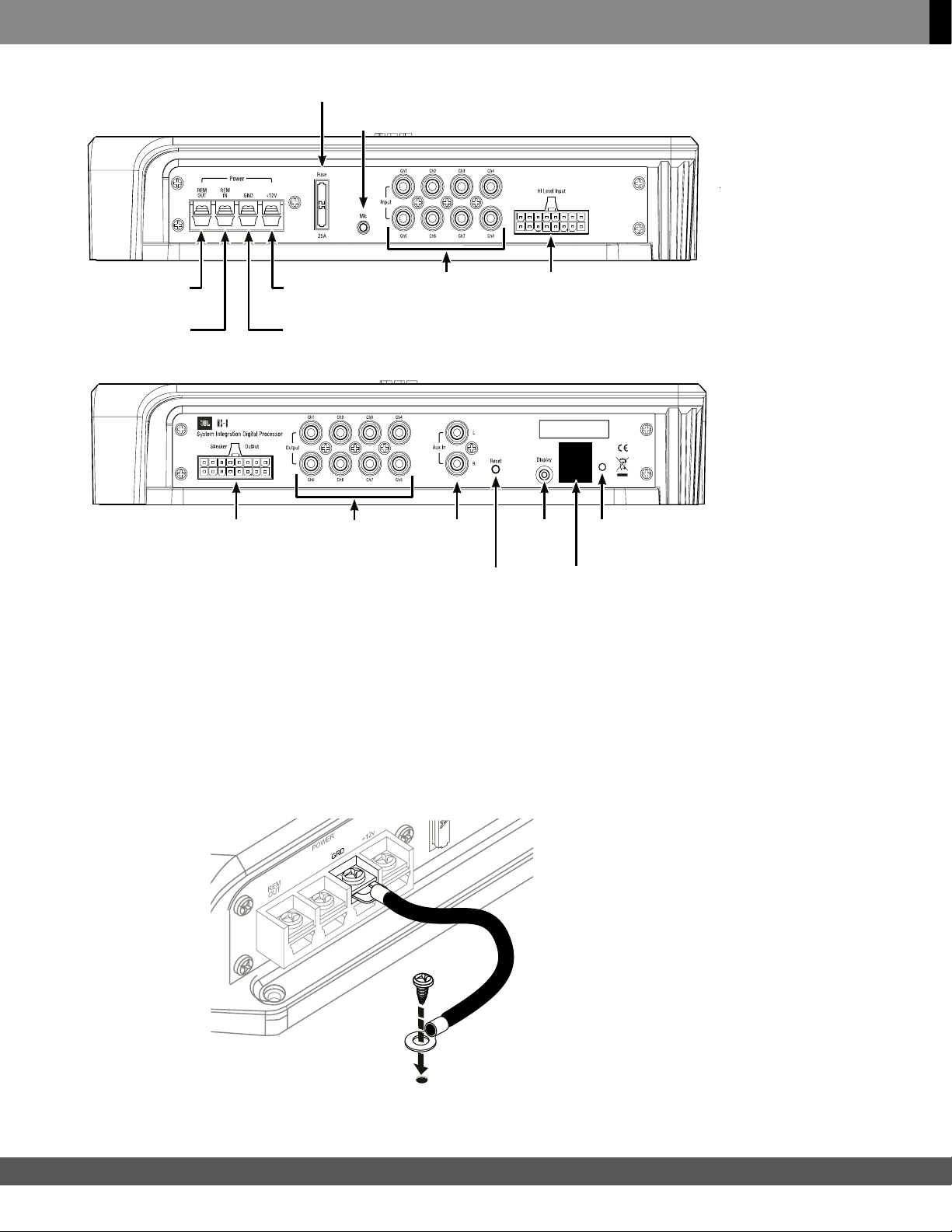
CONNECTIONS
Englis h
25A
fuse
Mic
connection
connection
Remote in
connection
Speaker output
connections
+12V
connection
GND
connection
Line output
connections
Line input
connections
Aux input
connections
Reset
button
POWER
IMPORTANT: Perform the power connections in the following order.
1. Gnd: Connect this terminal to a paint-free location on the vehicle chassis.
Hi Level inputRemote out
Display
connection
connection
REMOVE
FOR
SOFTWARE
UPDATE
Update
Power
LED
IMPORTANT: Use at least 12-gauge wire for this connection.
Chassis
ground
(unpainted)
5
www.jbl.com
CONNECTIONS
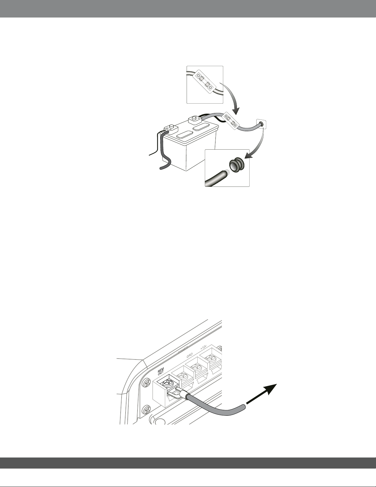
2. +12V: Connect this terminal to the vehicle batterys positive (+) terminal. Insert a 25A fuse in series on
the +12V wire no further than 18 inches (46cm) from the battery terminal.
IMPORTANT: Use at least 12-gauge wire for this connection.
25A fuse within
18" of battery
terminal
1 x 25A
+
-
3. Rem Out: Connect this terminal to the remote turn-on terminals of all ampliers in the system. The
output is +12V DC, 1A.
IMPORTANT:TheMS-8MUSTcontroltheturn-onsignalofalltheotherampliers
that follow the MS-8 in the signal path.
Ifyoursystemincludesafactory-installedoutboardamplier,theturn-onsignal
maybeavailableattheamplier.Ifyourfactoryamplierhasaturn-onwire,cutit
and connect the head-unit side of the wire to the MS-8 s Rem In terminal and the
ampliersideofthewiretotheMS-8’sRemOutterminal.
This arrangement will allow the factory stereo to turn the MS-8 on whenever the
stereoisturnedonandwillallowtheMS-8toturnthefactoryamplieronandoff.
It will also help to eliminate audible clicks and pops when the system turns on and
off.
Cable from MS-8
+12V terminal
Use a grommet
through the
firewall
www.jbl.com
To turn-on
terminals of
all system
amplifiers
6

CONNECTIONS
Rem In: Connect this terminal to the remote turn-on output of the systems source unit, if the
source unit has a remote turn-on output. Alternately, you can connect this terminal to the vehicles
accessory (ACC) power circuit. Any voltage over +4V DC at this terminal will trigger the MS-8 to
turn on.
NOTE: See Step 3 for more details about connecting the Rem In terminal to a factory-installed
stereo system.
To head unit
remote turn-on
or vehicle
ACC terminal
Englis h
AUDIO INPUTS
Many factory-installed systems include on-board equalization and crossovers that make simple
connection of aftermarket products difcult. The MS-8 includes the signal-summing circuitry, signalconditioning EQ and time-correction processing that are necessary to reconstruct a at, full-range,
two-channel signal when you use the MS-8 with factory-installed equipment.
Aftermarket head units with line outputs provide a at, full-range, two-channel signal on their front line
outputs, so you need to connect only those channels to the MS-8.
7
www.jbl.com
CONNECTIONS
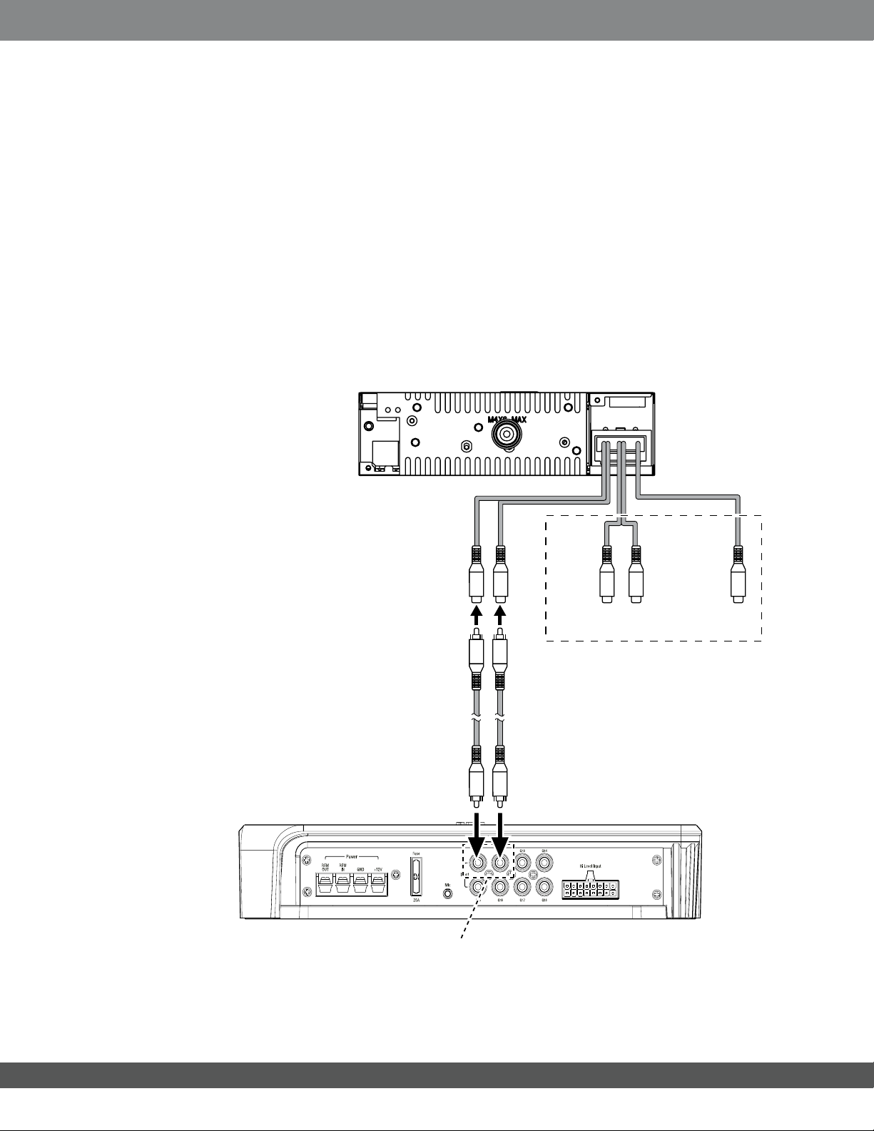
Connecting an aftermarket head unit
If you re using the MS-8 with an aftermarket head unit that has RCA-type outputs, connect the head unit s
front left and front right outputs to the MS-8s line inputs 1 and 2 only. Do NOT connect any other head-unit
output signals to the MS-8s line inputs 3 8. During the calibration/setup process, the MS-8 will normalize
the input signals and derive as many output signals as your speaker system requires.
IMPORTANT: Do not connect the head unit directly to any ampliers, including a subwoofer amplier. The
MS-8 s signal processing takes nearly 8ms, so any signals connected directly to a head-unit will be ahead
of the signals leaving the MS-8 by about 8ms. This difference will cause them to be out of sync with the
signals that pass through the MS-8. The MS-8 must generate all the signals that are sent to all of the
system s speakers!
Aftermarket head unit
MS-8 main unit
Front
line out
RCA
audio cables
Line inputs
1 and 2
Rear
line out
DO NOT USE
Subwoofer
line out
www.jbl.com
8

CONNECTIONS
Connecting a factory radio/head unit
If you will be connecting the MS-8 to a factory-installed stereo or a factory-installed amplier (often located in
the vehicles trunk), connect each of your factory front-speaker and subwoofer outputs to one of the MS-8s Hi
Level inputs. Be sure to connect the outputs for all speakers that are part of the vehicles front left and front right
speakers.
You can connect the factory front speaker outputs to any MS-8 Hi Level inputs, but factory stereo or amplier
subwoofer outputs MUST be connected ONLY to the MS-8 s channel 7 and/or 8 inputs. During the calibration/
setup process, the MS-8 will normalize the input signals and derive as many output signals as your speaker
system requires.
Factory stereo
wiring harness
Englis h
MS-8 main unit
Front left
+ –
Connect
+ –
+ –
+ –
Ch 1
Front right
Ch 2
Side left
Ch 3
Side right
Rear right
DO NOT USE
Ch 4
Ch 5
Subwoofer*
Center
Rear left
+ –
Connect
+ –
Ch 6
Ch 7
Ch 8
*NOTE: Subwoofers
MUST be connected
to MS-8 input 7
and/or input 8
NOTE: The above illustration shows only a general connection example and does not represent any particular
vehicle audio system.
Insert the included Hi Level input wiring harness into the MS-8s Hi-Level-input connector until it locks into place.
IMPORTANT: The MS-8 s Hi Level input wiring harness has gray and white wires. Each channel has a white
(positive or + ) wire and a gray (negative or ) wire. Each wire is labeled with its channel number and polarity,
and is pre-stripped for easy connection to your factory radios speaker outputs. Make sure that the ( + ) and
( ) wires do not touch each other. Touching wires can cause a short circuit that can damage the
MS-8 or your head unit.
To ensure proper polarity, connect each factory-radio positive (+) terminal to the respective
+ terminal on the MS-8. Connect the negative ( ) terminals in a similar way.
9
www.jbl.com
CONNECTIONS
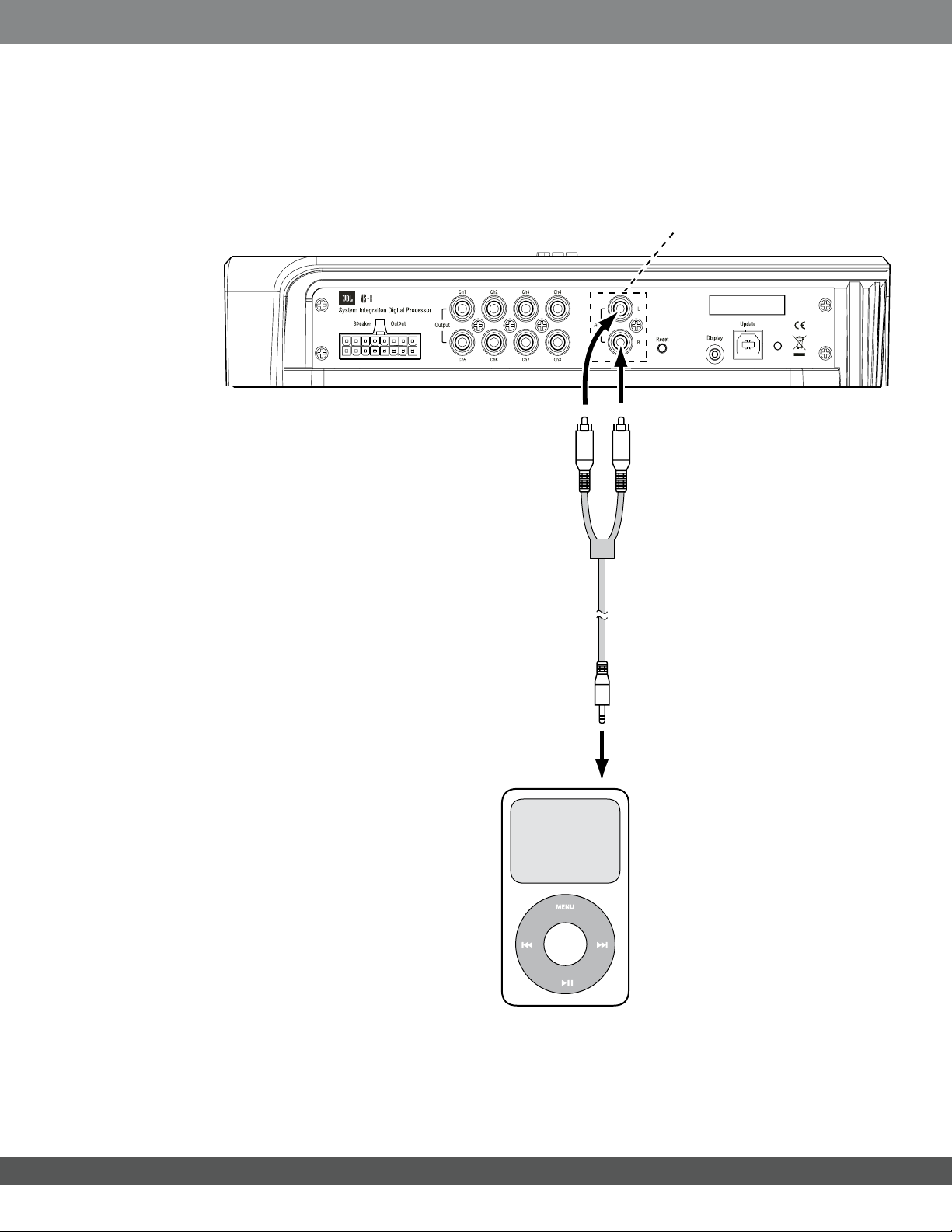
Aux input: If you will be using a portable music player or CD player as an auxiliary audio-source unit,
connect its line or headphone output to the MS-8's Aux input using a cable that terminates in stereo
RCA audio connections. You can switch between the MS-8's Head Unit inputs and Aux input in the
MS-8's Input Selection menu. See Main Menu, on page 35.
Aux
input
www.jbl.com
To
headphone
output
10

CONNECTIONS
AUDIO OUTPUTS
Congurations
You can congure the MS-8’s eight outputs in a variety of ways, depending on the speakers that are
installed in your vehicle. You can congure the MS-8 for a system with one-way (full-range), two-way or
three-way front speakers, a one-way or two-way center speaker, side speakers, rear speakers and one
or two subwoofers. Remember, however, that the total number of available channels is eight, so any
combination of front, center, side, rear and subwoofer channels cannot total more than eight. For example,
if you are allocating six channels for a pair of tri-amped, three-way front speakers, there will be only two
remaining channels, which will not accommodate a pair of rear speakers and a subwoofer.
If your system will include more than eight channels, use additional separate ampliers (connected to the
MS-8 s line outputs) for the additional channels. For example, if you want to build a 7.1-channel system
that includes bi-amped or tri-amped front speakers, use the MS-8 to generate the 7.1-channel outputs
(seven full-range and one subwoofer). Connect the MS-8s front line outputs to the inputs of an additional
crossover (or amplier containing an additional crossover) that will provide the separate channels required
to drive the front midbass, midrange and/or tweeters separately.
Use the Conguration Chart below to record which of your system’s speakers you have connected
to which of the MS-8s outputs. Keeping this record will simplify channel assignment during the setup
procedure. See Main Menu, on page 35.
Englis h
Output # Channel / Speaker Connected Output Connector Used
1 RCA SPEAKER
2 RCA SPEAKER
3 RCA SPEAKER
4 RCA SPEAKER
5 RCA SPEAKER
6 RCA SPEAKER
7 RCA SPEAKER
8 RCA SPEAKER
11
www.jbl.com
CONNECTIONS
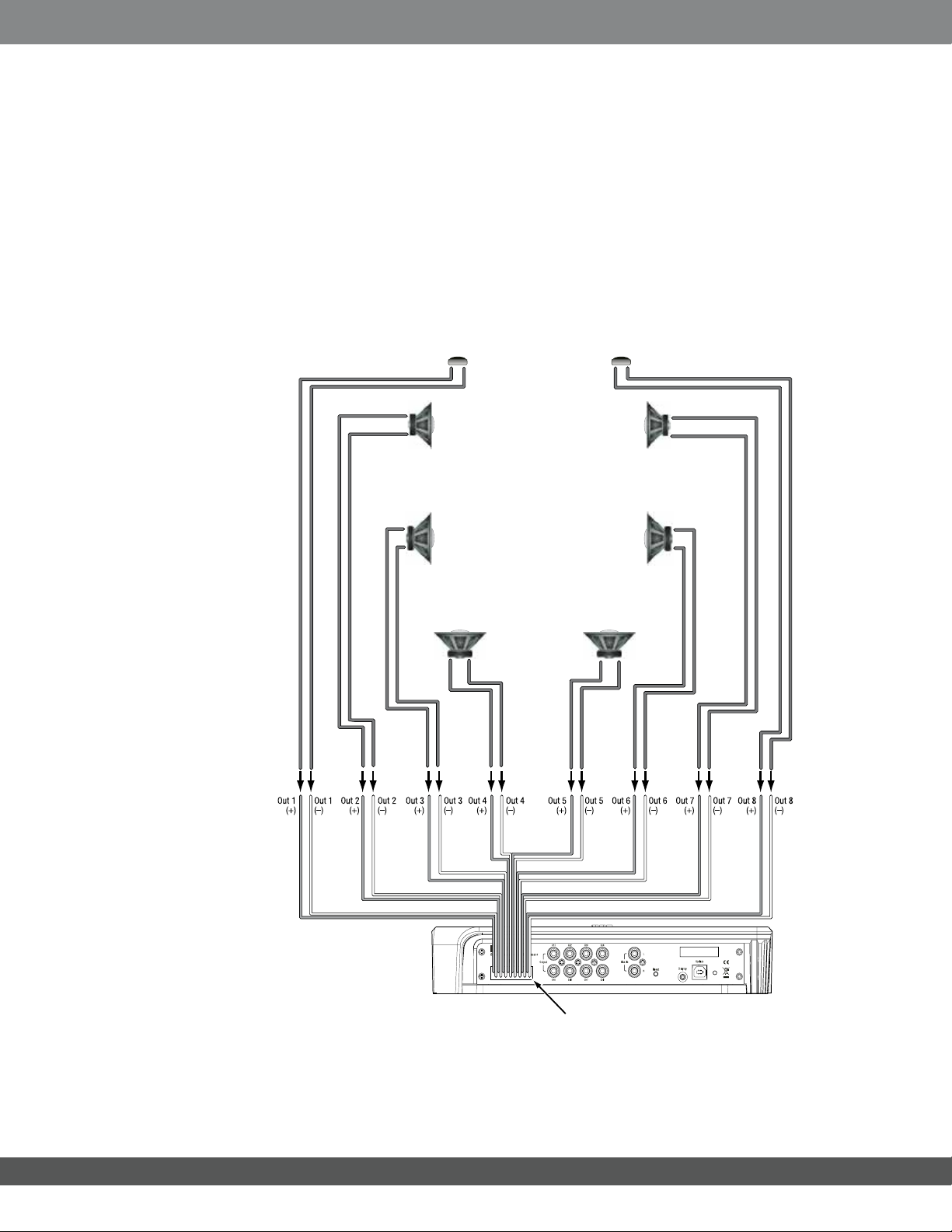
Speaker Outputs
If you’ll use the MS-8’s built-in power ampliers to drive your system’s speakers, connect the speakers to the
MS-8 s speaker outputs. Insert the included speaker-output wiring harness into the MS-8s speaker output
until it locks into place. See Main Menu, on page 35.
IMPORTANT: The MS-8 s speaker-output wiring harness s wires have clear insulation. Each channel has a
copper (positive or + ) conductor and a silver (negative or ) conductor. We have labeled each conductor
with its channel number and polarity, and pre-stripped it for easy connection to your systems speakers.
Make sure that the ( + ) and ( ) wires do not touch each other. Touching wires can cause a short
circuit that can damage the MS-8.
Left front
(tweeter)
+
– + –
+
Left front
(midrange)
–
Right front
(tweeter)
Right front
(midrange)
–
+
Vehicle
Speaker System
+
Left side
(coaxial)
–
Left rear
(coaxial)
+
–
Right side
(coaxial)
Right rear
(coaxial)
+
–
+
–
www.jbl.com
MS-8
main unit
Speaker-output
wiring harness
To ensure proper polarity, connect each MS-8 positive (+) terminal to the respective
+ terminal on the speaker. Connect the negative ( ) terminals in a similar way.
12
CONNECTIONS
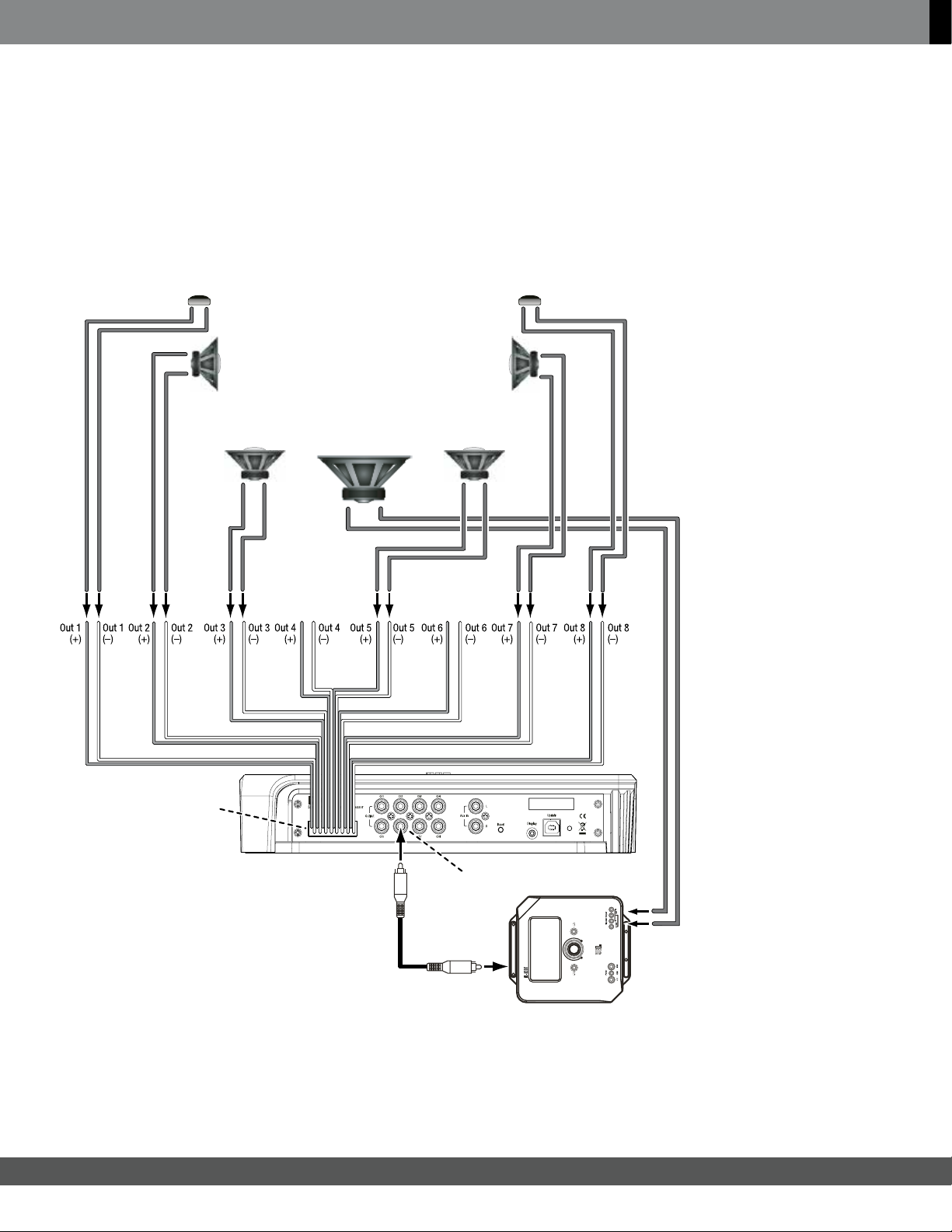
NOTE: You can power some of the system's speakers by the MS-8's ampliers and some by outboard
ampliers, but you should use only one connection type per output. For example, output channel 1 may use the
MS-8's amplifer OR an outboard amplier, but not both. Be sure to use the chart above to note which speakers
are connected to which MS-8 channels.
Englis h
Left front
(Tweeter)
+
– + –
+
–
Left front
(midrange)
Vehicle
Speaker
Right front
(midrange)
System
+
Left rear
(coaxial)
Subwoofer
–
+ –
Not
used
Right rear
+
Not
used
Right front
(Tweeter)
–
+
(coaxial)
–
Speaker output
wiring harness
Line output
#6
13
Subwoofer
amplifier
www.jbl.com
CONNECTIONS
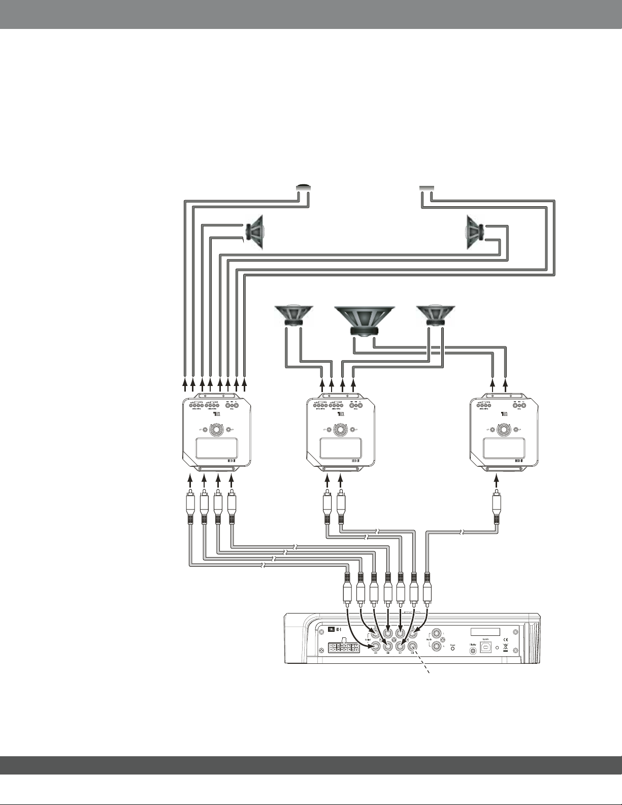
Line Outputs
If you’ll be using additional outboard power ampliers to drive your system’s speakers, connect their inputs to
the MS-8’s line-output connectors. You can power some of the system’s speakers by the MS-8’s ampliers
and some by outboard ampliers, but you should use only one connection type per output. For example,
Output Channel 1 may use the MS-8’s amplier OR an outboard amplier, but not both. Be sure to use the
chart above to note which speakers you have connected to which of the MS-8s channels.
Front
speaker
amplifier
Left front
(tweeter)
+
+
Left front
(midrange)
–
Left rear
(coaxial)
+
–
Rear
speaker
amplifier
Vehicle
Speaker
System
Subwoofer
+ –
Right front
(tweeter)
Right front
(midrange)
Right rear
(coaxial)
+
–+–
–
+
–
Subwoofer
amplifier
www.jbl.com
RCA
audio cables
MS-8 main unit
14
Ch. 8 is unused
in this example
CONNECTIONS
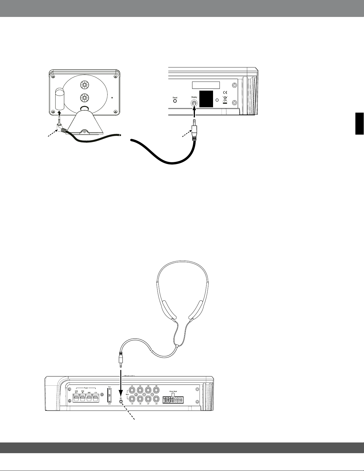
DISPLAY
Use the included 6m (19.7 ft) cable to connect the display unit to the MS-8s main unit s display connection.
Insert the cable s straight connector into the main unit and the right-angle connector into the display.
REMOVE
FOR
SOFTWARE
UPDATE
Englis h
Plug angled connector
into display
Plug straight connector
into main unit
NOTE: The display unit must be connected during setup but may be disconnected after setup and after
you ve made any additional adjustments in the Audio Controls menu (see Audio Controls Menu, on page 36).
If the display unit is disconnected after setup and nal adjustment, you will not be able to make any additional
MS-8 adjustments, and the remote control will not function. See Main Menu, on page 35.
MICROPHONE
The included binaural microphone headset must be connected to the MS-8 s Mic connection during the
calibration/setup process. Once setup is complete, unplug the microphone headset and store it in a safe
place.
IMPORTANT: Do not use any other microphone with the MS-8.
Connect to mic input
15
www.jbl.com
 Loading...