

Page 1
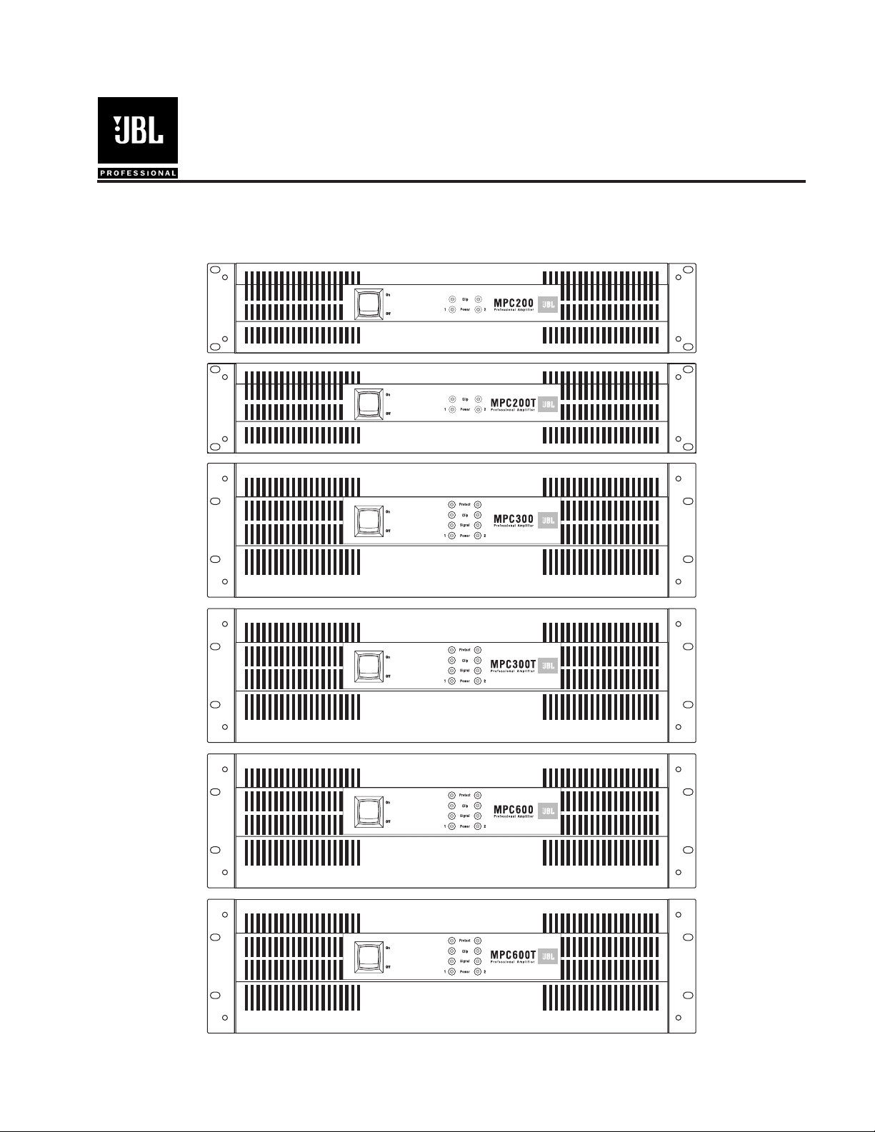
MPC Series
Power Amplifiers
Owner’s Manual
TD-000074-00
TD-000074-00
Rev. C
21
Page 2

Table of Contents
Table of Contents ................................................................................................................................................................................... 1
Warning notices ..................................................................................................................................................................................... 2
Speaker Output Shock Hazard ......................................................................................................................................................... 2
Rack Mounting Precautions ............................................................................................................................................................ 2
Lifting Precautions ........................................................................................................................................................................... 2
Description ............................................................................................................................................................................................ 3
Inputs ..................................................................................................................................................................................................... 5
Outputs .................................................................................................................................................................................................. 6
Driving Distributed Lines ..................................................................................................................................................................... 7
Low-Impedance and Distributed Speakers on T-Version Amplifiers .............................................................................................. 7
Using Multiple Distributed Line Voltages ...................................................................................................................................... 10
Bridged Mono Mode ............................................................................................................................................................................ 10
MPC200 & 200T Bridged Mono Configuration .............................................................................................................................. 11
MPC300, 300T, 600 & 600T Bridged Mono Configuration ............................................................................................................. 11
Bridged Mono Speaker Connection ................................................................................................................................................ 11
Low Impedance Bridged Mono ...................................................................................................................................................... 12
High Impedance Bridged Mono ..................................................................................................................................................... 12
Parallel Mono Configuration ................................................................................................................................................................ 12
Controls ................................................................................................................................................................................................ 13
Displays ................................................................................................................................................................................................ 13
AC Power .............................................................................................................................................................................................. 14
Operation .............................................................................................................................................................................................. 14
MPC200 & 200T .............................................................................................................................................................................. 14
MPC300, 300T, 600, & 600T ............................................................................................................................................................ 14
Protection Circuits ................................................................................................................................................................................ 14
Glossary ................................................................................................................................................................................................ 15
Specifications ........................................................................................................................................................................................ 16
Power Consumption ............................................................................................................................................................................. 17
Heat Emission ...................................................................................................................................................................................... 18
Troubleshooting ................................................................................................................................................................................... 19
For Further Assistance ......................................................................................................................................................................... 20
WITHIN THE UNITED STATES: .............................................................................................................................................. 20
General Information or Technical Assistance ................................................................................................................................. 20
Repairs ............................................................................................................................................................................................. 20
OUTSIDE THE UNITED STATES: ............................................................................................................................................ 20
1
Page 3
Cautions Sicherheitsvorschriften
Rack Mounting Precautions
To avoid damage to the amplifier mounting ears and/or
rack rails, the amplifier must be supported at all four corners
when used in portable racks.
Consult JBL Service Dept for availability of Rear
Support Brackets.
Lifting Precautions
In order to safely move or install the amplifier, it is
recommended that two persons share the weight when lifting
and positioning the unit.
CAUTION
TO AVOID ELECTRIC SHOCK, DO NOT INSERT FINGERS
OR OBJECTS INTO ANY OPENINGS IN THE CHASSIS.
Sicherheitsvorschriften für den Einbau in ein Gestell
Um Schäden auf den Befestigungsleisten des Verstärkers
und/oder den Gestellschienen zu vermeiden, muß der
Verstärker beim Einbau in ein tragbares Gestell an allen vier
Ecken gestützt werden.
Erkundigen Sie sich bei der JBL-Kundendienstabteilung
nach Stützen für die Rückseite des Verstärkers.
Sicherheitsvorschriften beim Hochheben
Um den Verstärker sicher zu verschieben oder
einzubauen, wird empfohlen, das Gewicht des Verstärkers
beim Hochheben und Verschieben gleichmäßig auf zwei
Personen zu verteilen.
VORSICHT
UM ELEKTRISCHEN SCHLAG ZU VERMEIDEN, KEINE
FINGERN ODER GEGENSTÄNDE IN ÖFFNUNGEN DES
GEHÄUSES STECKEN.
Warning notices
Speaker Output Shock Hazard
A MPC amplifier is capable of producing hazardous output voltages. To avoid electrical
shock, make sure the cover is in place over the output terminals, and do not touch any
exposed speaker wiring while the amplifier is operating.
Rack Mounting Precautions
To minimize twisting stress of the front mounting ears, the amplifiers internally mounted
output transformers are located close to the front panel. Nevertheless, when rack mounting
any MPC amplifier, make sure it is well supported at all four corners to avoid damage to
either the amplifier mounting ears or to the mounting rails. Rear support brackets are
available.
Lifting Precautions
In order to safely move or install the amplifier, it is recommended that two persons share the
weight when lifting and positioning the unit.
2
Page 4

Description
The MPC Series from JBL is a line of professional power amplifiers specifically designed for
contracting applications. There are six models, each with two independent channels. Each
model in the MPC Series line is available in a T version for driving either 200V, 140V, 100V,
70V, 50V, or 25V constant voltage lines and in a non-T versions for driving loudspeaker
systems with impedances as low as 2 ohms. (See section on bridging for information about
200V, 140V, and 50V drive capabilities).
Power CapabilitiesThe table below lists the power ratings under various load conditions:
ledoM4ΩΩΩΩΩ
002CPM
T002CPM
1
2×W5222×W053
2×W5222×W0532×W571
2ΩΩΩΩΩ
2
stloV001stloV07stloV52
3
3
2×W571
3
2×W051
003CPM
T003CPM
006CPM
T006CPM
1
FTC watts per channel, 20 Hz20 kHz, 0.1% THD
2
EIA watts per channel, 1 kHz, 1% THD
3
Watts per channel, band limited for 50 Hz15 kHz response, 0.25% THD
4
Watts per channel, band limited for 45 Hz15 kHz response, 0.25% THD
2×W0032×W054
2×W0032×W0542×W052
2×W0062×W009
2×W0062×W0092×W005
Channel SeparationEach channel has its own power transformer secondary to provide
maximum audio separation (minimum sound leakage) between the two channels, minimizing
interaction that can otherwise occur on amplifiers with a common power supply.
High EfficiencyThe MPC200, 200T, 300 & 300T utilize complementary Class AB linear
output circuitry. For improved efficiency, the MPC600 and 600T utilize Class H step-linear
complementary output circuitry using multi-rail power supplies.
High Cooling CapacityEvery MPC amplifier features a large diameter two-speed fan and
massive extruded aluminum heat sinks. The output devices couple directly to the heat sink.
This provides better cooling of the output devices while eliminating problematic insulating
wafers that are an integral part of most other amplifier designs. Forced air cooling in a backto-front direction provides for more effective cooling, preventing problems that otherwise
occur from a continual heat build-up inside the equipment rack, which occurs in amplifiers
with front-to-back or side-to-side flow schemes. These design factors allow the MPC amplifiers to work in high duty-cycle instances when many other professional amplifiers cannot.
4
4
4
2×W052
4
2×W005
4
2×W002
4
2×W004
Weight BalanceThe power transformers, as well as the output transformers on the T
models, are mounted in the front of the amplifier chassis, as close to the front mounting rails
as possible. This keeps the units center of gravity forward to minimize the twisting force on
the front mounting ears.
Rail SupportThe amplifier should be supported at all four corners, especially if it is in a
portable rack. The flow-through cooling scheme allows you to rack-mount the amplifiers on
top of the other, with no clearance necessary in between. This mounting technique also helps
support the weight of the upper amplifiers. In permanent fixed installations, the rear of the
amplifiers can receive physical support by installing the amplifiers at the bottom of the
equipment rack. Make sure that the direct weight of the back of the amplifier is supported
from the bottom of the rack.
Dimensions
a) HeightThe MPC200 and 200T are 2 rack spaces high. The MPC300, 300T, 600 and
600T are 3 rack spaces high.
3
Page 5
1
CH1
CH2
CH1
CH2
BRIDGE
MONO
BRIDGE
MONO
LOW IMPEDANCE
LOW IMPEDANCE
DIR. OUTPUT
DIR. OUTPUT
ISOL.OUTPUT
ISOL.OUTPUT
AUDIO TRANSFORMER
AUDIO TRANSFORMER
70V
70V
25V
25V
100V
100V
070100
070100
0
0
-dB -dB
10 10
88
66
44
22
24
24
18 18
14
14
STEREO
12
12
CH2 INPUT CH1
CH2 C H1
PARALLEL BRIDGE LEVELLEVEL
GROUND
INPUT
7 8 14
6
10
1113 13
711
109
BRIDGE
MONO
BRIDGE
MONO
CH1CH2
OUTPUT OUTPUT
0
0
-dB -dB
10 10
88
66
44
22
24
24
18 18
14
14
STEREO
12
12
CH2 INPUT CH1
CH2 C H1
PARALLEL BRIDGE LEVELLEVEL
GROUND
INPUT
7 8 14
613 13
7
109
11
10
CH2 CH2
BRIDGE
MONO
LOW IMPEDANCE
DIR. OUTPUT ISOL.OUTPUT
AUDIO TRANSFORMER
70V 25V
100V
070100
CH1 CH1
BRIDGE
MONO
LOW IMPEDANCE
DIR. OUTPUT ISOL.OUTPUT
AUDIO TRANSFORMER
70V 25V
100V
070100
0
0
-dB -dB
10 10
88
66
44
22
24
24
18 18
14
14
12
12
CH2 INPUT CH1
CH1CH2
LEVELLEVEL
GROUND
INPUT
13
7 8
1113
7
109
BRIDGE
MONO
BRIDGE
MONO
CH1CH2
OUTPUT OUTPUT
0
0
-dB -dB
10 10
88
66
44
22
24
24
18 18
14
14
12
12
CH2 INPUT CH1
LEVELLEVEL
GROUND
INPUT
CH1CH2
13
7 8
13
7
109
4 45
512 12
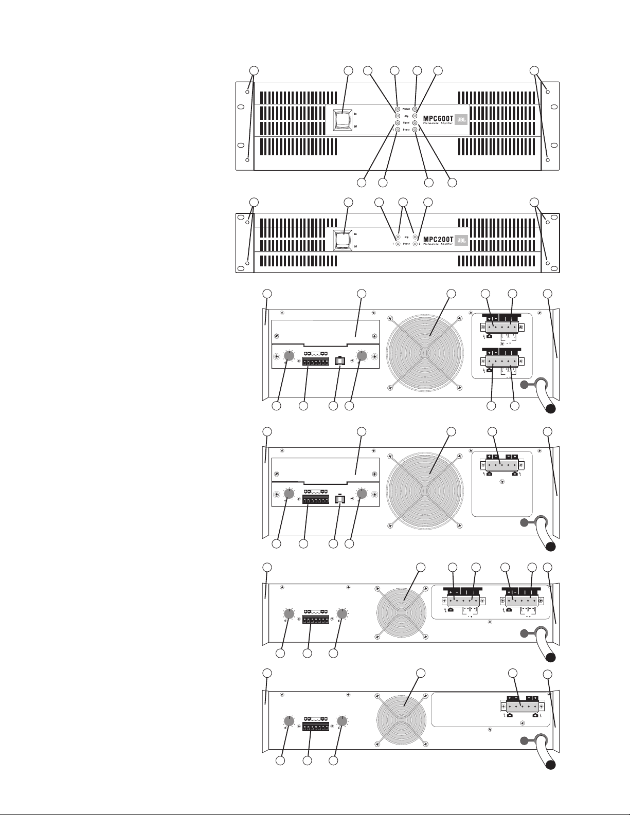
(MPC300, 300T, and 600 are similar)
MPC600T front panel
MPC200T front panel
(MPC200 is similar)
33
22
12 2412 12
MPC300T and 600T rear panel
1 Power Switch
2 Power Indicators (Ch. 1 & Ch. 2)
3 Signal Indicators (Ch. 1 & Ch. 2)
4 Clip Indicators (Ch. 1 & Ch. 2)
5 Protect Indicators (Ch. 1 & Ch. 2)
6 Accessory Slot Cover
7 Gain Control
8 Detachable Input Header Block
9 Cooling Fan
10 Shrouded Output Connector (Direct Outputs)
11 Shrouded Output Connector (Audio Transformer Outputs)
12 Mounting Holes for Optional Handles
13 Rear Support Ears
14 Parallel/Stereo/Bridge Switch
4
MPC300 and 600 rear panel
MPC200T rear panel
MPC200 rear panel
Page 6
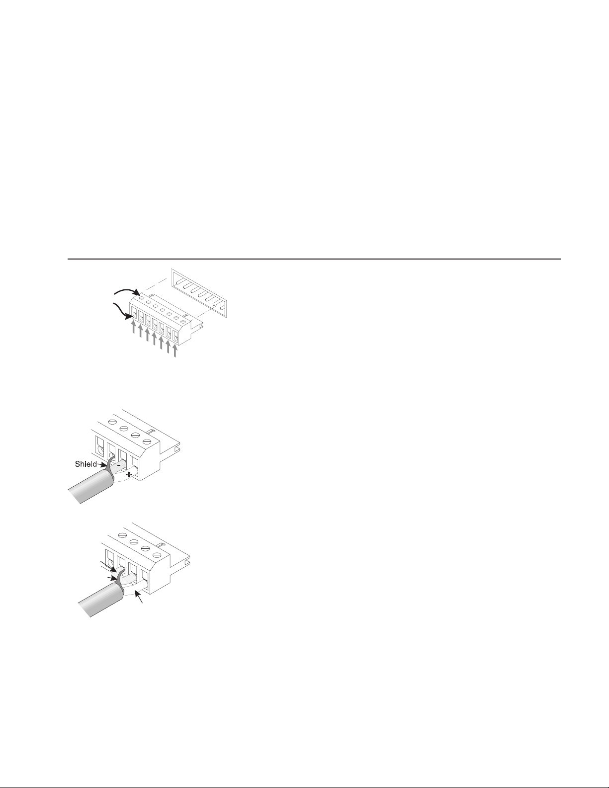
Inputs
Loosen screw,
insert wire here,
then tighten screw.
Ground
Ground
Channel 2+
Channel 2-
Ground
Channel 1-
Channel 1+
b) DepthThe amplifiers require a rack depth of 45.7 cm (18 in) to clear the rear support
ears. The rear panel is 42.9 cm (16.9 in) behind the plane of the front mounting rails, allowing
some room for routing of wires.
Stability, Reliability and ProtectionThe MPC Series is engineered for stability and
exceptional reliability, with protection for open or short circuits and mismatched (underimpedance) loads. Protection is also built-in for ultrasonic, infrasonic (subsonic) and RF. To
protect the loudspeakers the outputs mute during turn-on and turn-off and also in the event
of a DC load fault. (The MPC200 and 200T are AC coupled and cannot pass DC to the load;
thus DC fault muting is not required on these models.) See section on Protection Circuits for
additional information.
All protection circuitry automatically resets to normal when conditions assure safe operation.
MPC amplifiers feature balanced inputs, connected via a Euro-style 7-terminal
detachable header.
Wire jumper
between
input and
ground
Shield
Balanced ConnectionAttach as shown. Connect the (+) wire, (-) wire and ground wire to
terminal pins as marked.
Unbalanced ConnectionAttach input signal wires as shown. Use the non-inverting (+)
input and the ground terminals of the header, and also connect a wire jumper between the
inverting (-) input and the ground terminal. The wire jumper will prevent a reduction in gain
caused by a floating unbalanced input.
Signal conductor
Input SensitivitiesAudio signals of the following levels will produce full rated output
power at 8 ohms with the volume control turned up full.
MPC200 & 200T 0.96 Volts
MPC300 & 300T 1.02 Volts
MPC600 & 600T 1.00 Volts
5
Page 7
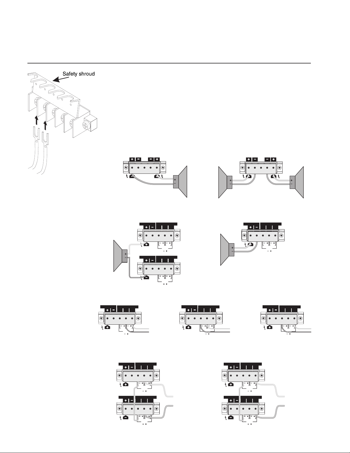
Outputs
Covered barrier strips located on the rear panel allow safe, shockproof speaker cable connections to the amplifier outputs. See the diagrams for details on connecting speakers and/or
distributed (25V, 70V, 100, 140V, and 200V) lines. Insulated connectors of the type shown are
recommended. Always make sure the amplifier is turned off before you change any output
connections or before lifting the safety shroud.
For driving 140V or 200V distributed lines, the amplifier must be set into bridged mono
mode. See Bridged Mono Mode section later in this manual for information about this
mode.
Lift safety shroud.
Loosen screw terminals.
Insert wire connectors
under screws.
Tighten screw terminals.
Lower safety shroud.
Output connection for “T” models,
CH1 CH1
DIR. OUTPUT ISOL.OUTPUT
Output connection for MPC, bridged mono mode. Output connection for MPC, parallel or stereo mode.
BRIDGE
MONO
CH1CH2
Ω
16
Ω
8
Ω
4
OUTPUT OUTPUT
BRIDGE
MONO
Output connection for MPC “T” models, bridged
mono mode.
AUDIO TRANSFORMER
LOW IMPEDANCE
16
8
4
CH1
DIR. OUTPUT
Ω
Ω
Ω
CH2
DIR. OUTPUT
LOW IMPEDANCE
BRIDGE
MONO
BRIDGE
MONO
070100
70V
AUDIO TRANSFORMER
070100
70V
100V
100V
CH1
ISOL.OUTPUT
25V
CH2
ISOL.OUTPUT
25V
Output connection for “T” models,
25 volt line.
LOW IMPEDANCE
AUDIO TRANSFORMER
070100
LOW IMPEDANCE
CH1 CH1
DIR. OUTPUT ISOL.OUTPUT
50 volt line.
AUDIO TRANSFORMER
070100
OUTPUT OUTPUT
8
Ω
4
Ω
2
Ω
BRIDGE
MONO
Output connection for MPC “T” models, direct low
impedance.
LOW IMPEDANCE
CH1 CH1
DIR. OUTPUT ISOL.OUTPUT
8
Ω
4
Ω
2
Ω
BRIDGE
MONO
Output connection for “T” models,
CH1 CH1
DIR. OUTPUT ISOL.OUTPUT
BRIDGE
MONO
AUDIO TRANSFORMER
070100
70V 25V
100V
100 volt line.
LOW IMPEDANCE
CH1CH2
AUDIO TRANSFORMER
070100
8
Ω
4
Ω
2
Ω
70V 25V
BRIDGE
MONO
100V
Output connections for “T” models, bridged
mono mode, 140 volt line
AUDIO TRANSFORMER
LOW IMPEDANCE
CH1
DIR. OUTPUT
CH2
DIR. OUTPUT
BRIDGE
MONO
LOW IMPEDANCE
BRIDGE
MONO
070100
70V
AUDIO TRANSFORMER
070100
70V
100V
100V
CH1
ISOL.OUTPUT
25V
CH2
ISOL.OUTPUT
TO 140V LINE
25V
BRIDGE
MONO
70V 25V
100V
BRIDGE
MONO
Output connections for “T” models, bridged
mono mode, 200 volt line
LOW IMPEDANCE
BRIDGE
MONO
LOW IMPEDANCE
BRIDGE
MONO
AUDIO TRANSFORMER
070100
70V
25V
100V
AUDIO TRANSFORMER
070100
70V
25V
100V
CH1
ISOL.OUTPUT
CH2
ISOL.OUTPUT
TO 200V LINE
CH1
DIR. OUTPUT
CH2
DIR. OUTPUT
70V 25V
100V
6
Page 8

Driving Distributed Lines
Make sure the sum of the power settings of all the speakers does not exceed the power rating of
the amplifier. Be aware that the actual power draw on some loudspeakers can vary considerably
from their tap labels. The tap labelings on some speakers refers to their power draw from the
distributed line, while on others they refer to the power delivered from the transformer into
the loudspeaker. In the latter case, the insertion loss of the transformer means that the actual
power draw from the amplifier is higher than the tap setting. Also, loudspeaker impedances
commonly vary with frequency, drawing more power at some frequencies than at others.
It is a good practice to allow a 20% safety margin. For example, if the amplifier has a power rating
of 250 watts, it is good practice to make sure the sum of the loudspeaker loads on the
distributed line is 200 watts or less.
Low-Impedance and Distributed Speakers on T-Version Amplifiers
MPC amplifiers are among the very few amplifiers that allow simultaneous use of low-impedance
speakers (connected to the LOW IMPEDANCE terminals) and distributed lines (connected to the
AUDIO TRANSFORMER terminals) not only on the same amplifier, but also on the same channel.
ApplicationsThis versatility can be very useful in some applications. Examples 1 through 3
illustrate combining distributed lines and low-impedance speakers on the same channel, while
example 4 describes using them on separate channels of the same amp.
Application Example #1: A theater or performance venueThe main loudspeakers
can be operated from the low-impedance output while speakers in a restroom, lobby area,
or green room can be driven from the 100V or 70V output of the same amplifier channel.
This saves money, eliminating the need for an additional dedicated distributed amplifier.
Application Example #2: A club or restaurantThe main loudspeakers can be driven
from the low-impedance output while the 100V or 70V output drives backstage monitors
or restaurant loudspeakers.
Application Example #3: Extending low frequency performanceAdding a low
impedance subwoofer (4Ω or 8Ω) to a distributed speaker system on the same channel
extends the sound spectrum with less risk of low frequencies saturating the transformers.
Balancing subwoofer and full-range speaker sensitivityThe sensitivity balance between full-range
speakers and subwoofers (the relative output level of each device) can be adjusted by choosing
appropriate tap settings on the speaker transformers and by positioning the subwoofer(s). For
example, suspending a subwoofer outdoors or in the center of a room, with no nearby boundary such
as a wall, floor, or ceiling, is acoustically the least efficient positioning; this is called placement in free
space because the sound radiates freely in all directions. Placing the subwoofer on one boundary
on a wall or in the center of the ceilingadds 3 dB of acoustic output because the boundary reflects
half the acoustic energy back into the listening space, reinforcing the other half. Moving the subwoofer
to a two-boundary junction (of 2 walls, a wall and ceiling, or a wall and floor) adds 3dB more. Yet
another 3dB can be obtained by placing the subwoofer in a corner (the junction of two walls and
the ceiling or two walls and the floor). Selective subwoofer placement therefore gives an adjustment
range of 9dB, which represents an approximate doubling of its perceived acoustic volume.
Application Example #4: Using two channels for delay applicationsWhen you need
delay for some, but not all, of the speakers (for example, to time-align speakers located in the
back of a venue), use both channels of the amplifier. The low-impedance output of one amp
channel can drive the main loudspeakers, while the same input signal is routed through a delay
and into the second channel to run a line of speakers for under-balcony or delayed-lobby use.
The delayed speakers can be either low-impedance, or more typically, 70V or 100V. This
eliminates the expense of an additional distributed amplifier.
7
Page 9

Loading an amp channelBe careful not to overload the channel when combining lowimpedance and distributed loads on the same amplifier channel, because either load affects
the amount of power available for the other. The next two paragraphs explain how they load
the amplifier output.
Internal output signal flowEach T-version amplifer output connects directly to the LOW
IMPEDANCE output terminals and to the primary of the audio output transformer. The
transformer secondary and its tap connect to the channels AUDIO TRANSFORMER
terminals labeled 0V, 70V, and 100V. As with all transformers, there is some insertion loss, so
slightly less power comes out of the transformer than goes into it from the amplifier circuitry. If
nothing is connected to the AUDIO TRANSFORMER outputs, the transformer will look like a
very high impedance to the amp output, and therefore virtually the entire power capacity of the
amp will be available to the low impedance load. If a lightly-loaded distributed line is connected
to the transformer outputs, the transformer will look like a somewhat lower impedance, and less
power will be available for the low-impedance load. The more heavily loaded the distributed
line is, the lower the impedance the transformer presents to the amps output circuitry.
Minimum impedance considerationsThe minimum load allowable for an MPC amp
is 2Ω per channel, whether low impedance, distributed line, or a combination of the two.
Therefore, if a 2Ω load is connected to the LOW IMPEDANCE terminals, then no
additional power is available for the AUDIO TRANSFORMER outputs. Likewise, as the
distributed lines power demand grows, the channels low-impedance capabilities diminish.
Computing channel loading
These two formulas can help you determine how to combine a low impedance and a distributed line on an amp channel
without overloading it. The first starts with a known low-impedance load and calculates the maximum power available for the
distributed line; the sum of the power taps on the speaker transformers should not exceed that amount. The second formula
starts with your knowing the total power draw on a distributed line and calculates the minimum load impedance, if any, that you
can connect to the LOW IMPEDANCE output terminals.
Due to frequency-dependent impedance variations, “constant voltage” loudspeakers can sometimes draw
more power from the distributed line than their transformer tap labels indicate. Although driving too low an
impedance will not harm your MPC amplifier, it might activate its protection circuitry or cause less-thanoptimal performance.
slightly higher nominal load impedance on the
demand (i.e., sum of all the power taps) on the
formulas suggest.
1) Computing maximum allowable distributed line loading with a known low-impedance load
The formula is:
MaxATP = [RatedLZP ((2 × RatedLZP)/Impedance)]/2
MaxATP is the sum of the power taps of the speakers connected to the AUDIO TRANSFORMER output(s).
Rated LZP is the maximum rated power of the amplifier into a 2Ω load.
Impedance is the load impedance connected to the LOW IMPEDANCE output.
Example: One channel of an MPC300T has a 4Ω load connected to the LOW IMPEDANCE output.
What is the maximum power left available to drive a distributed line? The answer is:
MaxATP = [450 ((2 × 450)/4)]/2 = 112 watts
When in doubt about actual loudspeaker characteristics, we recommend you use a
LOW IMPEDANCE
AUDIO TRANSFORMER
output and/or a slightly lower total power
outputs than what the following
8
Page 10

2) Computing the minimum low impedance load with a known distributed line load
The formula is:
MinZ = 2 × [RatedLZP/(RatedLZP (Actual HZP × 2))]
MinZ is the minimum load impedance that can be connected to the LOW IMPEDANCE output.
RatedLZP is the maximum rated power of the amplifier into a 2Ω load.
ActualHZP is the sum of all the power taps connected to the AUDIO TRANSFORMER output(s).
Example: One channel of an MPC300T has 100 watts of distributed loudspeakers connected to the 70V (or
100V) output. What is the minimum impedance load that can be connected to the LOW IMPEDANCE
output?
MinZ = 2 × [450/(450 (100 × 2))] = 3.6 ohms
The next-larger common speaker impedance is 4 ohms, so a load of 4 ohms or higher should work satifactorily.
The tables below are general guidelines on which combinations are acceptable.
MPC200T
Sum of Speaker Taps Connected to AUDIO TRANSFORMER Outputs
0 W 22 W* 44 W** 88 W*** 175 W****
Load connected to 2Ω ✔✗✗✗✗
LOW IMPEDANCE 4Ω ✔✔✔✗ ✗
output 8Ω ✔✔✔✔✗
16Ω ✔✔✔✔✗
32Ω ✔✔✔✔✗
MPC300T
Sum of Speaker Taps Connected to AUDIO TRANSFORMER Outputs
0 W 31 W* 62 W** 125 W*** 250 W****
Load connected to 2Ω ✔✗✗✗✗
LOW IMPEDANCE 4Ω ✔✔✔✗ ✗
output 8Ω ✔✔✔✔✗
16Ω ✔✔✔✔✗
32Ω ✔✔✔✔✗
MPC600T
Sum of Speaker Taps Connected to AUDIO TRANSFORMER Outputs
0 W 62 W* 125 W** 250 W*** 500 W****
Load connected to 2Ω ✔✗✗✗✗
LOW IMPEDANCE 4Ω ✔✔✔✗ ✗
output 8Ω ✔✔✔✔✗
16Ω ✔✔✔✔✗
32Ω ✔✔✔✔✗
* -9 dB from full
** -6 dB from full
*** -3 dB from full
**** full loading
✔ = Acceptable
✘ = Do not use
In general, if the CLIP indicator flashes occasionally, the amplifier is approaching its maximum long-term power capacity. If it
is lit about half the time, the amplifier channel will probably go into thermal protection within a few minutes.
9
Page 11

Using Multiple Distributed Line Voltages
The MPC amplifiers allow you to connect distributed lines to any of the 100V, 70V, and 25V
outputs at the same time. For example, a single channel could drive both a 70V and a 25V
line; such flexibility could save you the expense of an additional amplifier.
The total power of all the speakers connected to the AUDIO TRANSFORMER outputs should
always be less than the power rating of the channel. For example, an MPC300T is rated for a
maximum power output of 250 watts; therefore, the total of all the speakers power taps for
all the lines connected to the 100V, 70V, and 25V outputs must not exceed 250 watts.
MAKE SURE THA T LOCAL BUILDING CODES PERMIT THE USE OF THE
OUTPUT VOL TAGE YOU SELECT.
Bridged Mono Mode
Bridged Mono mode combines the output power of both channels to drive a single load.
Channel 2 is fed with an inverted signal from Channel 1. Thus, when one channel pushes,
the other pulls, providing twice the voltage swing of a single channel. The speaker connects
between the + terminals of each channel.
BRIDGED MONO MODE
CAUTION:
ALL MODELS
voltages as high as 160
volts rms are available
between the MPC
amplifier’s bridged terminals (200 volts at isolated
outputs).
MPC200T, MPC300T, and
MPC600T
operation)—Fully insulated
CLASS ONE wiring must be
used to connect the amplifier to the loudspeakers.
—Output
(140V and 200V
MODE BRIDGÉ MONO:
ATTENTION
TOUT LES MODÈLES
tensions de sorties aussi
élevée que 160 volts rms
sont disponible aux bornes
du amplificateur MPC en
mode bridgé mono (200
volts aux sorties isolés).
MPC200T, MPC300T, et
MPC600T
et 200V)—On doit utiliser
du câblage entièrement
isolé de CLASSE 1 pour
relier l’amplificateur aux
haut-parleurs.
(opération 140V
—Des
VORSICHT BEI MONOBRÜCKENBETRIEB:
ALLE TYPEN
den Ausgangsklemmen der
MPC-Verstärker können
Ausgangsspannungen bis
160 Volt RMS anliegen
(200 Volt bei isolierten
Ausgänge).
MPC200T, MPC300T, und
MPC600T
Betrieb)—Der Anschluß
muß vom Verstärker bis
zum Lautsprecher mit
vollisoliertem Kabel
erfolgen.
—Zwischen
(140V- und 200V-
PRECAUCIÓN PARA EL
MODO MONO PUENTE
TODO LOS MODELOS
Voltajes de salida de hasta
160 Vrms existen entre los
terminales de puente del
amplificador MPC (200
voltios a las salidas
aisladas).
MPC200T, MPC300T, y
MPC600T
y 200V)—Utilice cableado
de CLASE UNO totalmente
aislado para conectar las
altoparlantes.
(operación 140V
—
10
Page 12

Bridged Mono Input ConnectionThe following diagrams show input and output
connections for bridged mono mode. Note that the MPC200 and 200T models use a different
method for bridged mono than do the MPC300, 300T, 600 & 600T.
MPC200 & 200T Bridged Mono Configuration
1) To engage the bridged mono mode, jumper the barrier strip inputs on the rear, in accordance with the diagram printed under the barrier strip inputs.
2) Connect the amplifier input to channel 1 only with the jumpers as shown to channel 2.
Channel 1 and channel 2 gain control settings must be set the same!
MPC300, 300T, 600 & 600T Bridged Mono Configuration
1) Set the mode switch on the back panel to the bridge position.
2) Connect the signal to channel 1s input only. Do not connect an input signal to channel 2.
3) Use only channel 1s gain control to set the level. Both channels SIGNAL and CLIP
indicators should flash identically when the amplifier is operating.
Bridged Mono Speaker Connection
Low impedanceA speaker load of 4 ohms or higher can be connected across the two + low
impedance terminals of the two channels. The positive speaker wire goes to channel 1s +
terminal and the negative wire to channel 2s + terminal.
Audio transformerFor bridged mono operation using the AUDIO TRANSFORMER outputs,
a jumper wire must be connected between the AUDIO TRANSFORMER 0V terminals of
the two channels. See hookup diagrams.
When operating the amplifier in bridged mono mode, neither of the speaker
wires is at ground potential. Grounding either of the speaker wires can short out
one side of the power amplifier. Use the same precautions in handling and
dressing the wire as you would for the normal “hot” outputs. Ensure that neither
wire connects to ground anywhere along its length. Do not use grounded
autoformers on the loudspeakers.
11
Page 13

Low Impedance Bridged Mono
ApplicationsThe bridged mono mode produces higher output voltages with the trade-off
of requiring a higher impedance load and providing a slightly lower damping factor. Nevertheless, it is an effective way of providing very high power levels to loudspeakers such as 4Ω
or 8Ω subwoofers.
Minimum ImpedanceThe bridged mono configuration places the two channels of the
amplifier in series with each other. As such, each channel is seeing half the total load impedance. For example, connecting a 4Ω speaker in bridged mono results in each amp channel
seeing a 2Ω load. Since each channel individually is capable of driving a 2Ω minimum
impedance, a bridged mono MPC amplifier requires a 4
Power Drive CapabilitiesThe table below shows the low impedance power drive capabilities
into 4Ω and 8Ω loads of the MPC amplifiers in bridged mono mode:
ΩΩ
Ω
minimum impedance.
ΩΩ
Model Minimum Load Power Into 8
MPC200 & 200T 4Ω 450 Watts 700 Watts DO
MPC300 & 300T 4Ω 600 Watts 900 Watts NOT
MPC600 & 600T 4Ω 1200 Watts 1800 Watts USE
Ω
Power Into 4
Ω
Power Into 2
High Impedance Bridged Mono
Distributed System Bridged Mono ApplicationsPlacing the T models in bridged
mono mode permits higher drive voltages (140V and 200V) for reducing the effect of cable
resistance when driving extremely long loudspeaker lines. The loudspeakers and speaker
transformers connected to these lines must be capable of handling these higher voltages, and
the speaker cabling itself may be subject to special local or national safety code requirements.
Ω
Parallel Mono Configuration
The Parallel mode ties the two channel inputs together so that both are driven by the same
signal, without the need for external jumpers or wiring. After the inputs, both channels operate
independently. Though they carry the same signal, their gain controls affect only their
respective channels, and they must use separate speakers. Never parallel the speaker
outputs!
Only the models MPC300, 300T, 600, and 600T feature a mode switch; to place any of these
in parallel mode, set the switch to the Parallel position. To feed the same input signal to the
two channel inputs on models MPC200 and 200T, simply use jumper wires on the Euroblock
barrier strip input connector to parallel the two channel inputs: + to + and - to -.
12
Page 14

Controls
Displays
The channel attenuator controls, labeled in dB of attenuation, are located on the rear panel.
They have 11 detents and are adjustable from 0 dB (full gain) to ∞ (full attenuation).
The LED displays on models MPC200 and 200T are different from those on models
MPC300, 300T, 600, and 600T.
Models MPC300, MPC300T, MPC600, & MPC600T
Models MPC200 & MPC200T
13
Page 15

AC Power
Operation
The MPC amplifiers are available for 120 or 220240 VAC, 50 or 60 Hz operation. Each
amplifier is factory configured for the line voltage of the market into which it is sold.
Before first turning on the amplifier, turn the gain controls offi.e., fully counterclockwise
until you confirm the amplifier is operating properly.
MPC200 & 200T
Upon turning on the AC switch, the POWER LEDs will light and the amplifier will mute for
3 seconds. After this turn-on sequence, the amplifier should work normally.
Turn up the gain controls until the speakers produce the desired sound levels. The gain
controls should usually be kept in the upper half of their ranges for full performance and
most precise adjustability.
The POWER LEDs indicate the operation of each channel. The red CLIP LEDs indicate
overdrives of their respective amplifier channels.
The mute circuit cuts off the sound as soon as you turn off the amp and mutes for 3 seconds
when you turn on the amplifier. This blocks turn-on and turn-off thumps.
MPC300, 300T, 600, & 600T
When the amplifier is turned on, the red PROTECT LED on each channel lights for about 2
to 3 seconds, during which the output relays mute the speakers. After the turn-on muting
interval, the PROTECT LEDs turn off, the green POWER LEDs light and the output relays
enable the speaker outputs. Even during the muting interval, the yellow SIGNAL and red
CLIP LEDs operate normally if there is a signal present. If the CLIP LED is on while the
amplifier is muted, immediately cut the gain back to avoid a full power blast of sound when
the output relays close. If a channel stays muted with its PROTECT indicator lit, or if its
SIGNAL or CLIP indicators light when the gain is turned all the way down, it may be
defective; see the troubleshooting segment for more information.
The SIGNAL LED indicates signal levels that are -30 dB (referenced to full rated output
power) or higher.
The mute circuit cuts off the sound as soon as you turn off the amp, and the PROTECT
indicators remain lit until the power supplies are discharged.
Protection Circuits
The design of the MPC Series takes a comprehensive approach to protection.
RF ProtectionAs in all JBL power amplifiers, the inputs are resistively buffered for
overload and RF protection. Chassis bypass capacitors at inputs and outputs further improve
RF rejection.
14
Page 16

Short-Circuit ProtectionMPC amplifiers use the proven Output Averaging short circuit
protection system. The circuit permits full output current even into resistive or reactive 2Ω
load, but reduces the current safely by about 75% if the output is shorted.
Transient MutingTurn-on and turn-off muting keeps transientsboth from the amplifier
itself and from upstream equipmentfrom reaching the speakers when the amplifier is
turned on or off. The turn-on delay is approximately 3 seconds to allow the power supplies
and circuitry to stabilize. Turn-off muting occurs almost immediately after power is shut off.
Muting occurs whether power is turned on and off using the front panel power switch or
externally at the AC source.
Inrush ProtectionIt is common in some amplifiers for a large surge of current from the
AC power line to occur in the first seconds after the amplifier is turned on, during which the
depleted power supply capacitors charge. This inrush current can trip circuit breakers
severely limiting the number of amplifiers that can be switched on at the same timeand can
also damage the internal workings of the amplifier. To guard against this, models MPC300,
300T, 600, and 600T feature an internal NTC (negative temperature coefficient) thermistor in
series with the power switch and the transformer primary to limit inrush current. The
thermistor initially has a high resistance, which then diminishes rapidly as it warms to avoid
power loss. Typically, the inrush current of such an MPC amplifier is about what you could
expect from a typical amplifier of 1/3 to 1/2 the MPCs power rating. The smaller models,
MPC200 & 200T, have low inrush currents and do not require an NTC thermistor.
DC Fault ProtectionWhen the fault protection circuitry of an MPC300, 300T, 600, or
600T senses a DC voltage on a channel output, it actuates a relay that shorts the output to
ground to help protect the load against damage. (The amplifiers high pass filter, described
below, will itself block DC coming into the amplifier inputs.) The amplifiers Output Averaging protection circuitry limits current to further protect the output devices. If the DC
problem persists, that channel will go into thermal protection mode and should be serviced by
a qualified technician. The output stage of models MPC200 and 200T has AC coupling to
prevent it from passing DC.
Glossary
Thermal ProtectionTemperature sensors on the channel heatsinks and on the power
transformers are part of the thermal management circuitry. The sensors govern whether the
dual-speed fan runs at low or high speed. Below 55°C the fan runs at low speed; above it runs
at high speed. Above 85°C, the channel mutes for thermal protection.
Infrasonic / Subsonic and Saturation ProtectionBuilt-in second-order 50 Hz
(MPC200T) and third-order 45 Hz (MPC300T and 600T) Butterworth high-pass filtering
helps prevent saturation in speaker transformers by sharply reducing the amount of ultra-low
frequency energy the amplifier delivers. However, some lower-quality speaker transformers
have responses that do not extend that low; if you have any of these in your distributed line
system, you should insert a corresponding high-pass filter in the audio path before the
amplifier(s) unless you are also using subwoofers. All models have a subsonic filter to prevent
passing DC or excessive subsonic energy.
Distributed output, isolated output, audio transformer output, and constant voltage output all refer to the
terminals labeled AUDIO TRANSFORMER on the shrouded output connectors of the
MPC200T, 300T, and 600T models. Various terms for 200V, 140V, 100V, 70V, 50V, or 25V
systems are constant voltage speaker system, distributed speaker system, or an isolated system (if using
full-isolation transformers in the ampas do the MPC amplifiersand on the loudspeakers).
Direct output and low impedance output refer to the output terminals that drive low impedance loads,
such as 16Ω, 8Ω, 4Ω, and 2Ω speakers.
15
Page 17

Specifications
Direct Output Models Audio Transformer AND Direct Outputs
Electronics MPC200 MPC300 MPC600 MPC200T MPC300T MPC600T
Direct Power Out
4Ω bridge 1 kHz, 1% THD
8Ω bridge 45 Hz20 kHz, 1% THD 450 W 600 W 1200 W 450 W 600 W 1200 W
2Ω load/channel2, 1 kHz, 1% THD
4Ω load/channel2, 45 Hz20 kHz, 1% THD 225 W 300 W 600 W 225 W 300 W 600 W
Isolated Constant Voltage Out
200V or 140V Bridge: 350 W 500 W 1000 W
100V or 70V/Channel 175 W 250 W 500 W
25V/Channel: 150 W 200 W 400 W
Frequency Response (bandlimited by built-in highpass filter)
Direct Outputs: 20 Hz20 kHz ±0.2 dB 50 Hz20 kHz* 45 Hz20 kHz**
Isolated Outputs 50 Hz16 kHz* 45 Hz16 kHz**
Sensitivity (for full output): 0.96V 1.02V 1.0V 0.96V 1.02V 1.0V
Voltage Gain (direct outputs): 35 (31 dB) 40 (32 dB) 56 (35 dB) 35 (31 dB) 40 (32 dB) 56 (35 dB)
Output Circuit Type: AB AB H AB AB H
AB = Class AB+B complementary linear stage H = Class AB+B linear stage with Class H 2-step high-efficiency circuit
Distortion: SMPTE-IM less than 0.05%
Damping Factor: Greater than 200 (direct outputs)
Noise: Less than 100 dB below rated output (20 Hz to 20 kHz)
Input Impedance: 20k ohm balanced, 10k ohm unbalanced
Amplifier Protection: Short circuit, open circuit, ultrasonic, RF, thermal muting, over-temperature. Stable into reactive or under-impedance loads.
Load Protection: Turn-on / turn-off muting, DC-fault load grounding relay (MPC300, 300T, 600, 600T) with internal fault fuses.
Power Requirements: 100V, 120V, 220230V AC, 5060 Hz (Not user configurable)
Physical:
Controls
Front Panel: Power Switch
Rear Panel: Ch 1 & Ch 2 gain controls (11 detents: 0 dB, -2, -4, -6, -8, -10, -12, -14, -18, -24, off); Parallel/Stereo/Bridge
Connectors Input: Euro-style detachable header with screw-down terminal for bare wires
Cooling: Two-speed fan with back-to-front airflow
Net Weight: 14 kg (27 lb) 19 kg (42 lb) 23 kg (50 lb) 18 kg (37 lb) 25 kg (55 lb) 31 kg (67 lb)
Shipping Weight: 17 kg (33 lb) 23 kg (49 lb) 27 kg (58 lb) 21 kg (42 lb) 28 kg (62 lb) 34 kg (75 lb)
Indicators: CLIP: Red
Dimensions (H × W × D)
MPC200T & 200: 89 × 483 × 455 mm (rack depth 450 mm); 3.5 × 19 × 17.9 in (rack depth 17.7 in); 2 RU high
MPC300T, 300, 600T, & 600: 133 × 483 × 455 mm (rack depth 450 mm); 5.25 × 19 × 17.9 in (rack depth 17.7 in) 3 Rack Units high
Agency Approvals: UL & CUL approved, CE compliant, and approved by Lucasfilm for THXÒ installations
Optional Accessories: MP-RRB1: Rear Rack Bracket for 3RU (5.25 in) models (set of 2)
1
1
700 W 900 W 1800 W 700 W 900 W 1800 W
350 W 450 W 900 W 350 W 450 W 900 W
* -3 dB @ 50 Hz, -0.2 dB @ 20 kHz ** -3 dB @ 45 Hz, -0.2 dB @ 20 kHz
switch (except MPC200 & 200T)
Output: Covered barrier strip for bare wires or spade terminal
POWER: Green
PROTECT: Red (except MPC200 and 200T)
SIGNAL: Green (except MPC200 and 200T)
MP-RRB2: Rear Rack Bracket for 2RU (3.5 in) models (set of 2)
1
Typical
2
Both channels drive, 120V 60 Hz mains.
JBL continually engages in research related to product improvement. Changes introduced into existing products without notice are an expression of that philosophy.
16
Page 18

Power Consumption
Some background on AC ratings is necessary to fully understand power consumption
specifications. Essentially, there are three ratings of interest: (1) the legal operating current as
measured by the Safety Agencies, (2) the maximum expected average current draw under
worst-case program material, and (3) the peak current draw at full output power.
All major safety agencies around the world measure amplifier current and temperature rise
under the same normal operation conditions, using a pink noise signal with an average
power equal to 1/8 of maximum rated average power. To put this level in perspective, typical
music and speech signals contain peaks of 12 dB to 20 dB above the average signal level, so
operating at 1/8 of rated average power will typically result in heavily clipped program
material.
JBL engineering standards call for the ability to operate at 1/3 power, in order to meet worstcase demands.
The electrical current consumption at 120 VAC for each audio power level and load impedance
is shown in the table below. Multiply the current figures by 0.5 for 230 VAC operation.
Note: the audio test signal for 1/8 and 1/3 power testing is pink noise; the signal for fullpower testing is a 1 kHz sine wave.
ledoMdaoLlennahCrewoPlluFrewoP3/1 *rewoP8/1eldI
8Ω 8+ Ω A7.5A4.3
4Ω 4+ Ω A2.9A2.5
,002CPM
T002CPM
2Ω 2+ Ω A3.31A4.7
V001,V07,V52A7.8A0.5
8Ω 8+ Ω A7.7A9.4
4Ω 4+ Ω A5.21A4.7
,003CPM
T003CPM
2Ω 2+ Ω A8.81A0.11
V001,V07,V52A2.11A7.6
8Ω 8+ Ω A7.41A4.8
4Ω 4+ Ω A32A4.21
,006CPM
T006CPM
2Ω 2+ Ω A33A5.61
V001,V07,V52A12A9.01
A3.2A4.0
A5.3A4.0
A9.4A4.0
A3.3A4.0
A3.3A6.0
A8.4A6.0
A2.7A6.0
A5.4A6.0
A5.4A8.0
A1.6A8.0
A0.8A8.0
A7.5A8.0
* Analogous to normal audio program with moderate to heavy clipping.
17
Page 19

Heat Emission
Any power that enters the amplifier through the power cord and does not exit through the
speaker outputs turns into heat, which the amplifier must rid itself of by exhausting it to the
outside. In indoor use this may present a challenge to the buildings air conditioning system.
Use the table below to predict the heat that will be emitted by your amplifier.
Note: the audio test signal for 1/8 and 1/3 power testing is pink noise; the signal for fullpower testing is a 1 kHz sine wave.
ledoMdaoLlennahCrh/UTBrh/lackrh/UTBrh/lack
rewoPlluFrewoP3/1 *rewoP8/1eldI
rh/UTB rh/lackrh/UTBrh/lack
8Ω 8+ Ω 546361516551
4Ω 4+ Ω 56218130601762 038 0125822
,002CPM
T002CPM
2Ω 2+ Ω 04320950071924
V001,V07,V5256314430501462
8Ω 8+ Ω 60414530201752
4Ω 4+ Ω 52527367161804
,003CPM
T003CPM
2Ω 2+ Ω 856447112352836
V001,V07,V5201027053051973 1411 88292285
8Ω 8+ Ω 19712549321213
4Ω 4+ Ω 03330481802525
,006CPM
T006CPM
2Ω 2+ Ω 896573416413397
V001,V07,V5227731598332985
* Analogous to normal audio program with moderate to heavy clipping.
015 8215822
5921 6235822
008 2025822
406 25192285
129 23292285
0921 52392285
508 30279257
2221 80379257
1161 60479257
0821 32379257
18
Page 20

Troubleshooting
PROBLEM: Channel will not come out of muting.
Reduce the gain to ∞ attenuation. If this releases the muting, raise the gain back up slowly
while you watch the SIGNAL and CLIP indicators. The problem may be an abnormal signal
(possibly with excessive ultrasonic energy, for example) that could otherwise damage your
speakers.
If reducing the gain control to ∞ attenuation does not release muting, the channel is
defective or overheated (see overheating section).
PROBLEM: No Sound (MPS 300, 300T, 600 & 600T only)
Is the PROTECT LED lit? If so, the channel may be muted (see below).
Is the SIGNAL LED lit or flashing? If so, the speaker may be open or blown, there may be
an open circuit in the speaker wiring, or there may be an open circuit in the internal output
wiring of the amplifier.
If the SIGNAL indicator is dark, there may not be enough signal, or none at all. Try turning
up the rear panel attenuators or boosting the signal level of the device that is sending the
signal to the amplifier.
If the SIGNAL indicator shows little or no activity but the CLIP LED is lit or flashing,
there is probably a short circuit in the speaker wiring, especially if the PROTECT indicator
starts flashing. It is also possible, but less likely, that the channels output relay is defective and
will not open, thereby short-circuiting the channel output and producing the same symptoms.
PROBLEM: Hum in the audio
Because of its grounded-collector output transistor configuration, which maximizes thermal
efficiency, the signal ground on an MPC amplifier cannot be lifted. The amplifiers balanced
inputs are meant to reject hum, but if hum remains a problem, check the tightness of the two
mounting screws on the input panel (except MPC200 & 200T). If they are loose, the panel
itself might not be well grounded to the chassis. In some cases, such as when the audio signal
cables are routed near lighting dimmers that use triacs, you may need to use external input
transformers because of the extremely high noise field produced by the dimmer circuitry.
PROBLEM: Channel goes into muting, with PROTECT LED on (MPS300, 300T, 600
& 600T only)
If the fan is running full speed, the channel probably suffers from severe overheating.
Unless there is a blockage in the flow of cooling air, the channel should return to normal
within a minute or so (see overheating section).
If the fan is not running at full speed, or the channel does not reset to normal after a cooldown period, the muting is probably caused by a DC fault or other amplifier failure (especially
if the SIGNAL or CLIP indicators are lit even with the attenuator turned all the way down).
PROBLEM: Overheating
The thermal management system features a two-speed fan that modulates the cooling air
flow over the heatsinks in response to the cooling needs. If the air flow is blocked, however,
or if the amplifier is overdriven into very low impedance loads, the amplifier could overheat
even though the fan is running at full speed.
MPC200 & 200T: At 85°C both channels mute. The POWER indicator remains lit, although
the CLIP indicator is dark. The amplifier remains this way until the temperature drops to a
safe level.
MPC300, 300T, 600 & 600T: At 85°C, the channels output relay mutes the output. The
channel remains muted until the temperature drops to a safe level. Even while the channel is
muted, the SIGNAL and CLIP indicators function normally. If the CLIP indicator is flashing
or continuously lit, reduce the gain to hasten the cool-down and prevent repeated thermal
shutdowns.
19
Page 21

For Further Assistance
WITHIN THE UNITED STATES:
General Information or Technical Assistance
For more information on JBL products, including these power amplifiers, contact your
nearest JBL Professional products dealer or the JBL factory at the address below.
Repairs
Please do not ship your amplifier to JBL or a JBL authorized repair facility without prior
authorization. You may obtain that authorization by contacting the factory or repair facility
directly. Please ship amplifiers in the original packing materials or equivalent to prevent
further damage during shipment, and insure the shipment adequately. Mark the return
materials authorization number (RMA) clearly on the outside of the package and on any
correspondence.
JBL Professional
8400 Balboa Blvd.
Northridge, CA 91329
(818) 894-8850
OUTSIDE THE UNITED STATES:
For general information, technical assistance or repairs, contact the JBL Professional Distributor in your country.
20
Page 22

JBL Professional 8500 Balboa Boulevard, P.O. Box 2200 Northridge, California 91329 U.S.A.
A Harman International Company MPC MANUAL 6/98
22
 Loading...