

JBL MPA275 User Manual
MPA Series
Power Amplifiers
Owner’s Manual
MPA275
MPA400
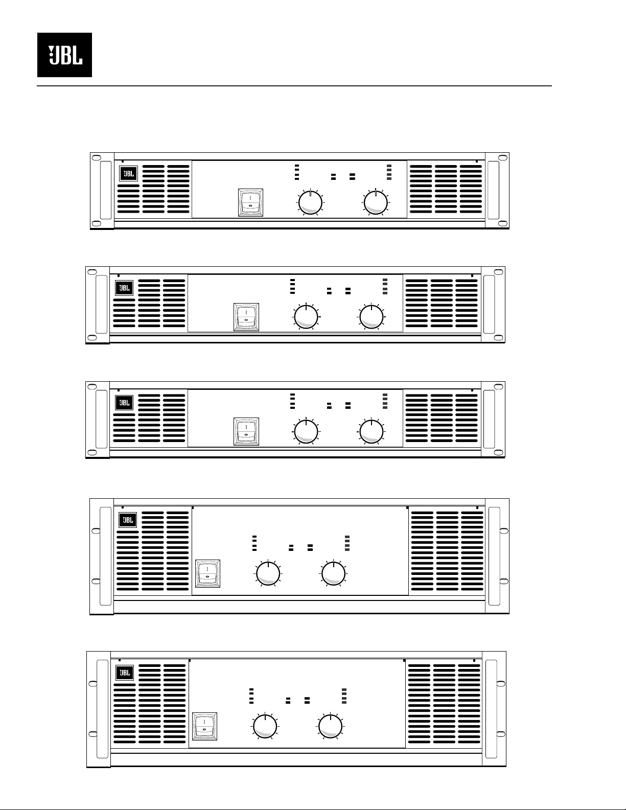
MPA275
MPA400
MPA600
P r o f e s s i o n a l A m p l i f i e r
P r o f e s s i o n a l A m p l i f i e r
P r o f e s s i o n a l A m p l i f i e r
Clip
-10dB
-20dB
Signal Present
10
12
14
18
24
48
Clip
-10dB
-20dB
Signal Present
10
12
14
18
24
48
Clip
-10dB
-20dB
Signal Present
10
12
14
18
24
48
8
0
8
6
2
0
8
6
2
0
6
4
2
1-CHANNEL-2
Protect
Power
4
1-CHANNEL-2
Protect
Power
4
1-CHANNEL-2
Clip
14
18
24
14
18
24
14
18
24
Signal Present
12
48
Signal Present
12
48
Signal Present
10
12
48
Clip
-10dB
-20dB
10
Clip
-10dB
-20dB
10
-10dB
-20dB
8
6
4
2
0
8
6
4
2
0
8
6
4
2
0
Protect
Power
MPA600
MPA750
MPA750
MPA1100
P r o f e s s i o n a l A m p l i f i e r
Clip
-10dB
-20dB
Signal Present
10
8
12
14
18
6
24
2
48
0
P r o f e s s i o n a l A m p l i f i e r
Clip
-10dB
-20dB
Signal Present
10
8
12
14
18
6
24
4
2
48
0
Protect
Power
4
1-CHANNEL-2
Protect
Power
1-CHANNEL-2
14
18
24
14
18
24
Signal Present
12
48
Signal Present
10
12
48
Clip
-10dB
-20dB
10
8
6
4
2
0
Clip
-10dB
-20dB
8
6
4
2
0
MPA1100
Cautions
Sicherheitsvorschriften
Rack Mounting Precautions
To avoid damage to the amplifier mounting ears
and/or rack rails, the amplifier must be supported at all
four corners when used in portable racks.
Consult JBL Service Dept for availability of Rear
Support Brackets.
Lifting Precautions
In order to safely move or install the amplifier, it is
recommended that two persons share the weight when
lifting and positioning the unit.
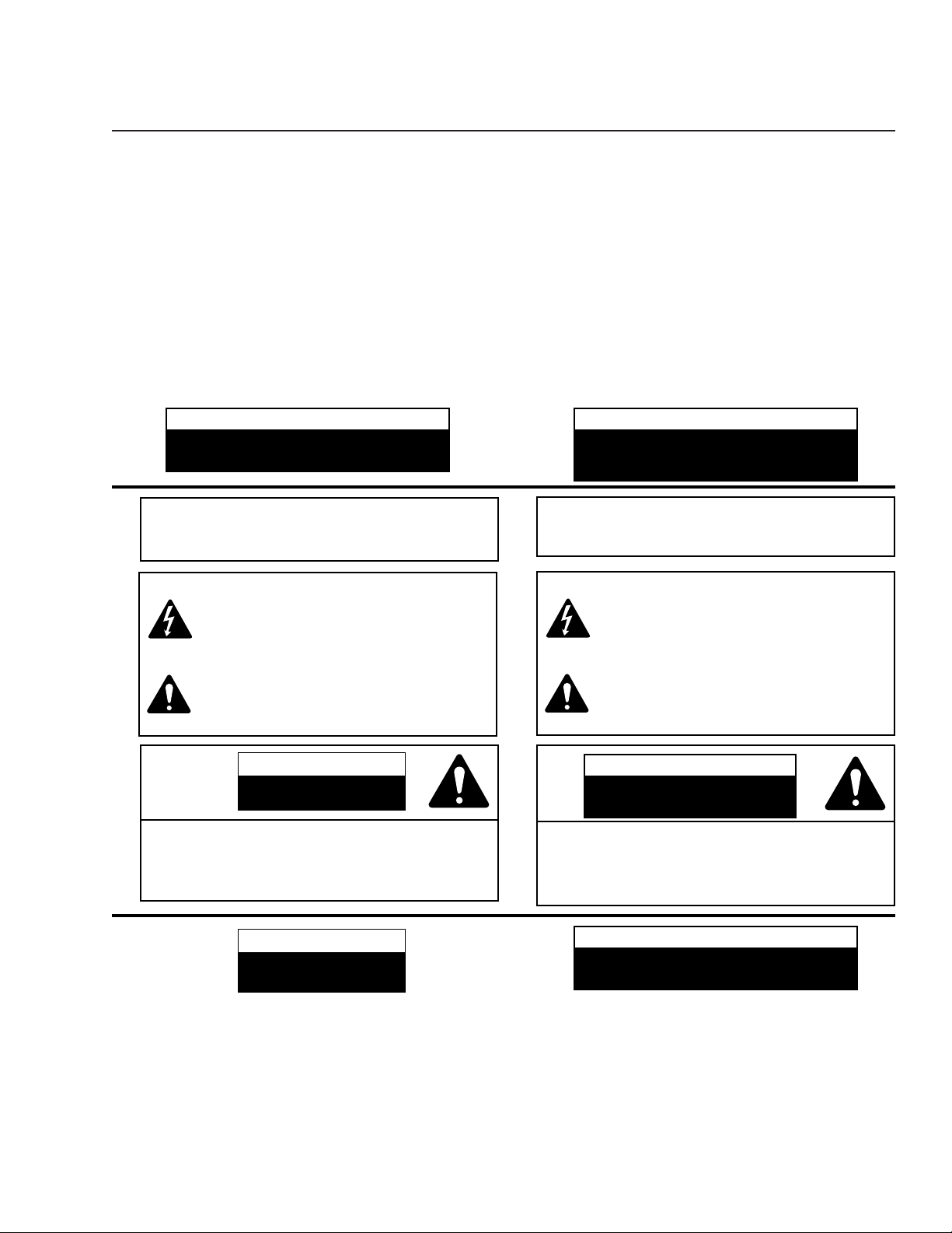
CAUTION
TO AVOID ELECTRIC SHOCK, DO NOT INSERT FINGERS
OR OBJECTS INTO ANY OPENINGS IN THE CABINET.
WARNING: TOPREVENTFIREORELECTRIC
SHOCK
, DONOTEXPOSETHISEQUIPMENTTORAIN
ORMOISTURE
.
Explanation of Graphical Symbols
The lightning flash with arrowhead symbol, within an equilateral triangle, is intended to alert the user to the presence
of uninsulated “dangerous voltage” within the product’s
enclosure that may be of sufficient magnitude to constitute
a risk of electric shock to humans.
The exclamation point within an equilateral triangle is
intended to alert the users to the presence of important
operating and maintenance (servicing) instructions in the
literature accompanying the product.
Sicherheitsvorschriften für den Einbau in ein Gestell
Um Schäden auf den Befestigungsleisten des
Verstärkers und/oder den Gestellschienen zu vermeiden, muß der Verstärker beim Einbau in ein tragbares Gestell an allen vier Ecken gestützt werden.
Erkundigen Sie sich bei der JBLKundendienstabteilung nach Stützen für die
Rückseite des Verstärkers.
Sicherheitsvorschriften beim Hochheben
Um den Verstärker sicher zu verschieben oder
einzubauen, wird empfohlen, das Gewicht des
Verstärkers beim Hochheben und Verschieben gleichmäßig auf zwei Personen zu verteilen.
VORSICHT
UM ELEKTRISCHEN SCHLAG ZU VERMEIDEN, KEINE
FINGERN ODER GEGENSTÄNDE IN ÖFFNUNGEN DES
WARNUNG:
ELEKTRISCHENSCHLÄGENDASGERÄTNICHMITREGEN
ODERFEUCHTIGKEITINBERÜHRUNGBRINGEN
Erklärung der graphischen Symbole
Der Blitz mit nach unten zeigendem Pfeil in einem gleichseitigen
Dreieck weist den Benutzer auf das Vorhandensein einer
unisolierten, “gefährlichen Spannung” im Gehäuse hin, die stark
genug sein kann, einer Person einen elektrischen Schlag zu versetzen.
Das Ausrufezeichen in einem gleichseitigen Dreieck weist den
Benutzer auf nichtige Betriebs - und Wartungsvorschriften in den
Beiliegenden Unterlagen des Geräteshin.
GEHÄUSES STECKEN.
ZURVERMEIDUNGVONFEUERODER
.
CAUTION
RISK OF ELECTRIC SHOCK
DO NOT OPEN
CAUTION: TOREDUCETHERISKOFELECTRIC
SHOCK, DONOTREMOVETHECOVER. NOUSER-
SERVICEABLEPARTSINSIDE. REFERSERVICINGTO
QUALIFIEDSERVICEPERSONNEL
.
CAUTION
RISK OF ELECTRIC SHOCK:
OPEN ONLY IF QUALIFIED
AS SERVICE PERSONNEL
To reiterate the above warnings: servicing instructions are for use by qualified personnel only. To avoid
electric shock, do not perform any servicing other than
that contained in the Operation Instructions unless you
are qualified to do so. Refer all servicing to qualified
service personnel
VORSICHT
GEFAHR EINES ELEKTRISCHEN
SCHLAGES NICHT ÖFFNEN
VORSICHT:
SCHLAGESZUVERMINDERN
ENTFERNEN
INNERN
BEDIENUNGSPERSONAL
UMDASRISIKOEINESELEKTRISCHEN
,
KEINEBENUTZERBEDIENUNGSTEILEIM
.
.
BEDIENUNGNURDURCHQUALIFIZIERTES
ABDECKUNGNICHT
.
VORSICHT
GEFAHR EINES ELEKTRISCHEN SCHLAGES: NUR VON
QUALIFIZIERTEM WARTUNGSPERSONAL ZU ÖFFNEN
Eindrigliche Warnung: Wartungsvorschriften dienen
nur der Benutzung durch qualifiziertes Personal. Zur
Vermeidung eines elektrischen Schlages keine anderen
als die in den Betriebsvorschriften beschriebenen
Wartungsarbeiten ausführen, es sei denn, Sie sind dafür
qualifiziert. Wartungsarbeiten sind von qualifiziertem
Wartungspersonal auszuführen.
1

2
Cautions .................................................................................................................1
Unit Description ....................................................................................................3
General Information....................................................................................................3
Open Input Architecture™ Slots.................................................................................3
Feature Identification...................................................................................................4
Installation.............................................................................................................5
Inputs ...........................................................................................................................5
Outputs ........................................................................................................................5
Input Connections.......................................................................................................6
Changing XLR Polarity.................................................................................................7
To Parallel the Inputs..................................................................................................7
Bridged Mono Mode ...................................................................................................8
AC Power Connection.................................................................................................9
Operation .............................................................................................................10
Controls......................................................................................................................12
Gain Control Lockout................................................................................................12
Displays......................................................................................................................12
Typical Power Up, Operation, Power Down Behavior...........................................12
Maximum Long-Term Output Power........................................................................14
Protection Circuits......................................................................................................14
Specifications.......................................................................................................16
Power Output Ratings ...............................................................................................17
Troubleshooting ..................................................................................................19
Illustrations
Figure 1. Open Input Architecture Slots.....................................................................3
Figure 2. Rear and Front Views of 2-Space High Amplifiers ....................................4
Figure 3. Rear and Front Views of 3-Space High Amplifiers ....................................4
Figure 4. Neutrik Speakon Connector Wiring for Speaker Outputs.........................5
Figure 5. Typical Unbalanced Connection.................................................................6
Figure 6. Portable Balanced System ...........................................................................6
Figure 7. Installed Balanced System...........................................................................6
Figure 8. Ground Bus Connection..............................................................................6
Figure 9. Jumper Positions for XLR Polarity Reversal................................................7
Figure 10. Switch Settings for Bridged Mono Operation...........................................7
Figure 11. Connection Options of Speaker Load for Bridged Mono ......................8
Figure 12. Speakon Connection Details for Bridged Mono Operation. ...................8
Figure 13. Gain Control Lockout...............................................................................12
Figure 14. LED Displays During Normal Operation................................................13
Figure 15. LED Displays During Abnormal Operating Conditions .........................13
Tables
Table 1. JBL MPA Series AC Power Consumption
versus Load Impedance With 110, 115 & 120 V Mains ..............................9
Table 2. JBL MPA Series AC Power Consumption
versus Load Impedance With 220, 230 & 240 V Mains.............................10
Table 3. LED Display Operation...............................................................................11
Table 4. Output Ratings With 110, 115 and 120 V Mains........................................16
Table 5. Output Ratings With 110, 115 and 120 V Mains........................................17
Table of Contents
3
The MPA275, MPA400, MPA600, MPA750 and MPA1100 are high-efficiency professional power amplifiers, with two independent channels, respectively capable of delivering 275, 400, 600, 750 and 1100 watts into a four ohm load (per channel), and
substantially more power into lower impedance loads. Semi-toroidal power transformers (one per channel in the MPA750 and MPA1100) are mounted in each front
corner, as close as possible to the rack ears and rails. The rear panels are 16.9 inches
behind the front mounting plane, so an extra rack depth allowance (i.e., more than
18 inches) will be needed to clear XLR or Speakon connections. The built-in fan
cooling takes air in the rear, exhausting through front vents. Due to the flow-through
cooling, amplifiers may be racked with zero clearance in between, which also helps
support the weight. Rear support within the rack must be used in portable applications.
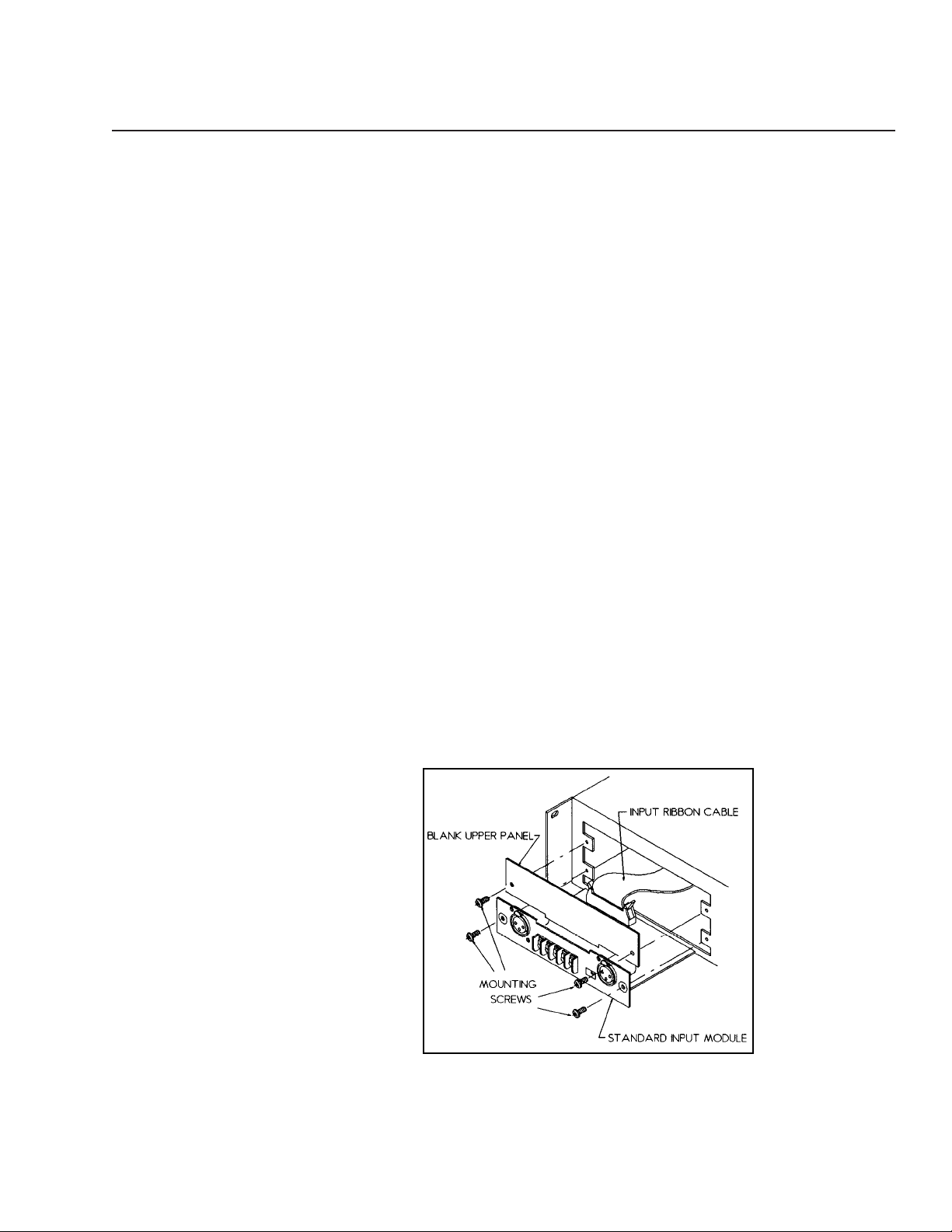
Open Input Architecture™ Slots
Provided with each MPA Series amplifier is a standard input module. This module
and the upper input cover panel can be removed, permitting future upgrades.
Internally, a ribbon cable runs behind both of these “slots.” The ribbon cable connects to the rest of the amplifier and carries several levels of DC power, and (for each
channel) the input signals, speaker output monitor, muting status, clip activity, thermal status, and power-on status. These signals are provided to support future remote
control and monitoring schemes as they become available. The JBL Marketing department will be happy to entertain suggestions for input modules.
The “standard input board” which is shipped with each amplifier has balanced
XLR and barrier strip inputs, bridging and input-parallel switches, and footprints for
passive rolloffs and popular input isolation transformers (more info is available on
request).
Unit Description
Figure 1. Open Input Architecture Slots.
4
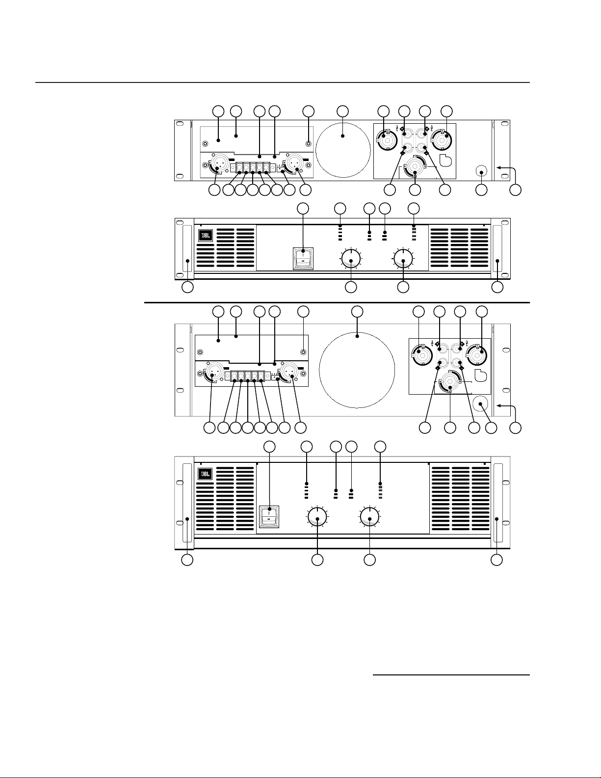
Figure 2. Rear and
Front Panel for
2–Space High
Models (MPA275,
MPA400 & MPA600)
Figure 3. Rear and
Front Panel for
3–Space High
Models (MPA750
and MPA1100)
Rear Panel Features
1. Upper Input Slot
2. Upper Input Cover Panel
3. Slot Product Mounting Screws
4. Lower Input Slot
5. Standard Input Board
6. Channel 2 XLR Input Connector
7. Channel 1 XLR Input Connector
8. Channel 2 (+) Terminal Block Input
9. Channel 2 (–) Terminal Block Input
10. Channel 1 & 2 Ground Terminal
11. Channel 1 (–) Terminal Block Input
12. Channel 1 (+) Terminal Block Input
13. Configuration Selector Switch
14. Fan
15. Channel 2 Speakon Output Connector
16. Channel 1 Speakon Output Connector
17. Channel 2 (+) Binding Post *
18. Channel 2 (–) Binding Post *
19. Channel 1 (+) Binding Post *
20. Channel 1 (–) Binding Post *
21. Dual-Channel Out Speakon Connector
22. Rear Rack Support (Left and Right)
23. Power Cord
Front Panel Features
24. Unit Power Switch
25. Channel 1 Level Display
26. Channel 2 Level Display
27. Channel 1 Power & Protection Display
28. Channel 2 Power & Protection Display
29. Channel 1 Gain Control
30. Channel 2 Gain Control
31. Handle (Left and Right)
*Banana output for 100–115 VAC Units Only
Unit Description
1 2 4 5 3 14 15 1617 19
CHANNEL 2
OUTPUT
– BRIDGED MONO +
CHANNEL 1
OUTPUT
GND
P1
P3
CHANNEL 2
INPUT
GND
+– –+
11
MPA600
P2
PARALLEL
STEREO
BRIDGE
CHANNEL 1
126 7
13
GND
P1
P3
DUAL CHANNEL
OUTPUT CONNECTOR
STEREO
4 OHM MIN PER CH
18 20211098
24 27 28 26
P r o f e s s i o n a l A m p l i f i e r
25
18
14
24
Clip
-10dB
-20dB
Signal Present
10
12
48
8
0
6
4
2
1-CHANNEL-2
Protect
Power
29
18
14
24
CH 2
Signal Present
10
12
48
30 3131
Clip
-10dB
-20dB
8
6
4
2
0
P2
SENSITIVITY
1 VOLT
IMPEDANCE
20K BAL
10K UNBAL
1 2 4 5 3 14 15 1617 19
CHANNEL 2
OUTPUT
P3
CHANNEL 2
GND
P1
INPUT
GND
+– –+
11
P2
GND
P1
PARALLEL
STEREO
BRIDGE
CHANNEL 1
MPA1100
P3
126 7
13
24 27 28 26
25
P r o f e s s i o n a l A m p l i f i e r
Clip
-10dB
-20dB
Signal Present
10
8
12
14
6
18
4
24
2
48
0
Protect
Power
1-CHANNEL-2
18
14
24
Signal Present
12
48
DUAL CHANNEL
OUTPUT CONNECTOR
STEREO
4 OHM MIN PER CH
Clip
-10dB
-20dB
10
8
6
4
2
0
P2
SENSITIVITY
1 VOLT
IMPEDANCE
20K BAL
10K UNBAL
CH 1
+
BRIDGED MONO
8 OHM MIN
–
23 22
CH 1
BRIDGED MONO
8 OHM MIN
+
–
CHANNEL 1
OUTPUT
23 22
– BRIDGED MONO +
CH 2
18 20211098
29
30 3131
5
Installation
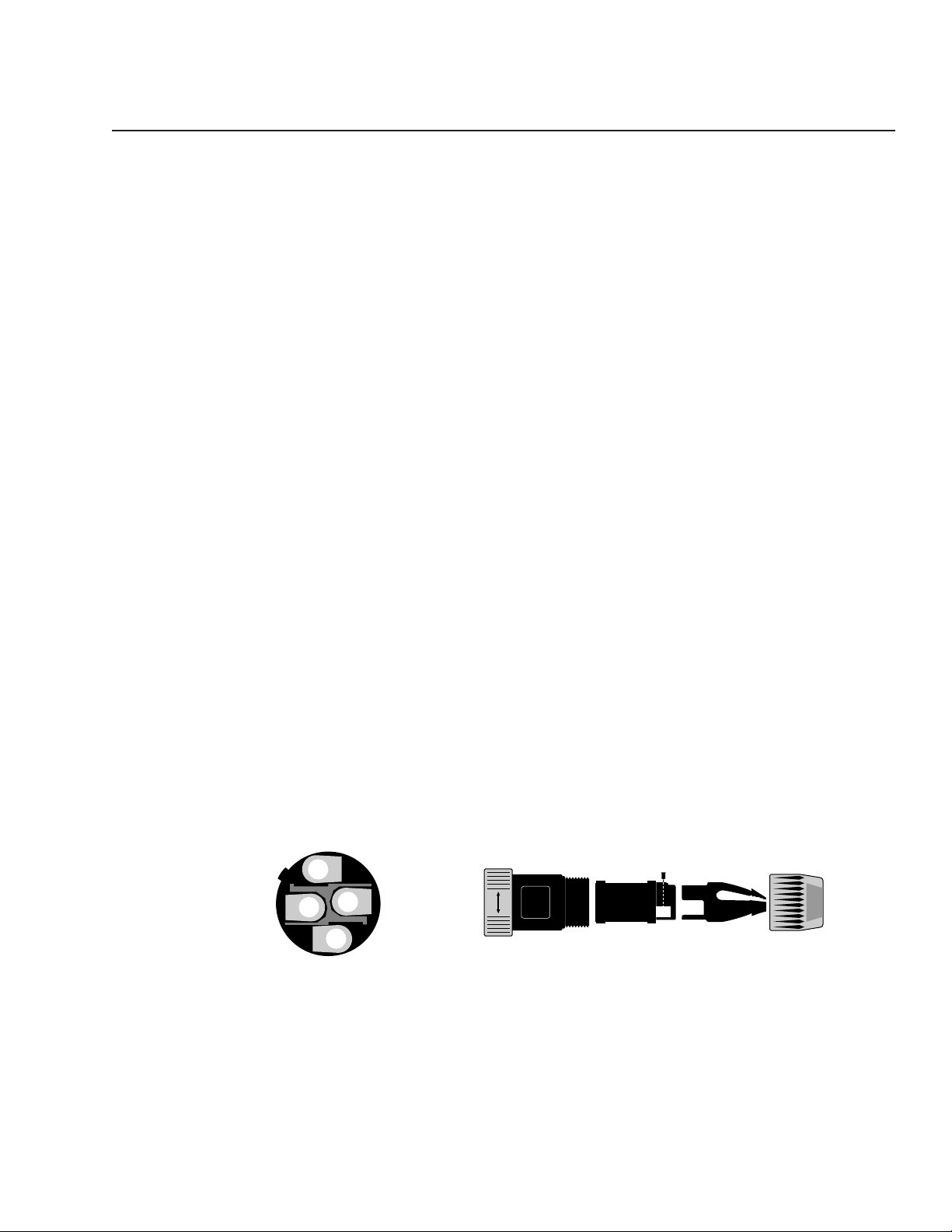
Figure 4. Neutrik Speakon Connector Wiring for Speaker Outputs
Exploded view (side)
Connection Terminals
Inputs
Balanced input connections are available via barrier strip or XLR connectors. The unit
is shipped with pin 2 high (see subsequent instructions to change polarity). As usual,
for unbalanced inputs, the unused terminal should be terminated to ground (the
negative input terminals on the barrier strip are located adjacent to the ground terminal for this purpose).
Input sensitivity is 1 Vrms, and impedance is 20 kilohm balanced, 10 kilohm
unbalanced, as is typical of JBL amplifiers.
The input jacks are located on a removable panel which has a toggle switch for
(1) bridged-mono (2) normal stereo, or (3) paralleling the inputs. See page 2 for more
information about the Open Input Architecture slots.
Outputs
Speaker connections are made via standard red/black 5-way binding posts, or by
Neutrik NL4FC Speakon connectors. The Speakon for each channel uses the standard
wiring of:
Pin 1- = Speaker Ground
Pin 1+ = Speaker Hot
Pin 2- = [Not used]
Pin 2+ = [Not used]
In addition, a central Speakon is provided with the standard stereo wiring of:
Pin 1- = Ch 1 Ground
Pin 1+ = Ch 1 Hot
Pin 2- = Ch 2 Ground
Pin 2+ = Ch 2 Hot
2–
2+
1+
1–
NEUTRIK
SPEAKON
NL4FC
SWISS MADE
Xx
6
Input Connections
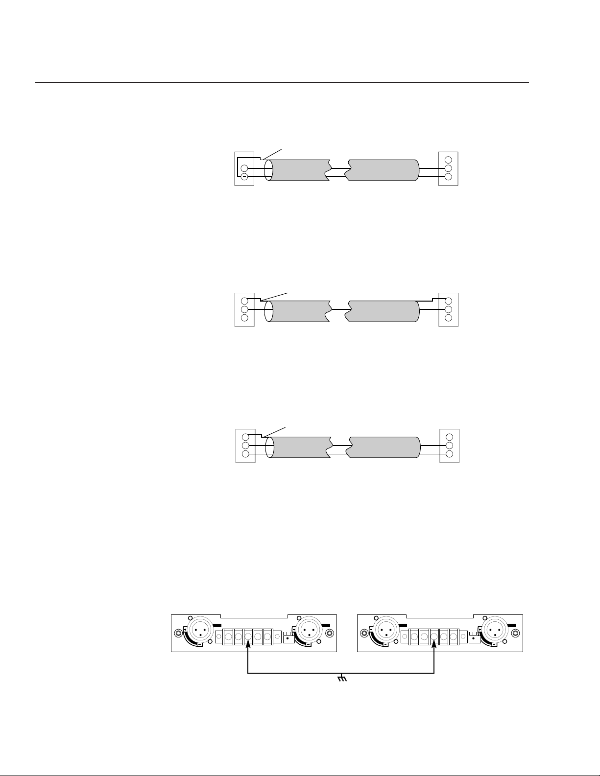
Figure 5. Typical Unbalanced Connection
To connect an unbalanced source to the input of an MPA amplifier, “+” should be
connected to pin 2, and “-” to pin 3 The “-” terminal should also be connected to the
shield at the source only. Pin 1 should not be connected at the amplifier.
Figure 6. Portable Balanced System
In a portable system using a source unit with balanced outputs, a standard XLR cable
wired pin to pin (with pin 1 connected to the shield at both ends) should be used.
Figure 7. Installed Balanced System
In an installed system using a source unit with balanced outputs, pin 1 should be
connected to the shield at the source, with no connection to pin 1 at the amplifier.
If, after wiring the input as shown above, any hum or buzzing is present, connect
the GND terminals of all amplifiers together. This bus should then be connected to a
stable earth ground. It may also be necessary to connect the chassis of the input
source device to the ground bus, particularly when using an unbalanced source.
Figure 8.
Output
(Source)
+
Unbalanced
Shield
MPA Input
1
2
3
Balanced
Output
(Source)
1
2
3
Balanced
Shield
MPA Input
1
2
3
Balanced
Output
(Source)
1
2
3
Balanced
Shield
MPA Input
1
2
3
Balanced
SENSITIVITY
1 VOLT
IMPEDANCE
20K BAL
10K UNBAL
P2
P3
CHANNEL 2
INPUT
+– –+
GND
P1
CHANNEL 1
PARALLEL
P2
GND
STEREO
BRIDGE
P1
P3
GND
SENSITIVITY
1 VOLT
IMPEDANCE
20K BAL
10K UNBAL
P2
P3
CHANNEL 2
INPUT
+– –+
GND
P1
CHANNEL 1
PARALLEL
P2
GND
STEREO
BRIDGE
P1
P3
GND
 Loading...