

Page 1
MultiMedia Series Loudspeakers
Media Sub2000
Service Manual
JBL Consumer Products
250 Crossways Park Dr.
Woodbury, New York 11797
Page 2

- CONTENTS -
SPECIFICATIONS & TEST PROCEDURE……………….….………..1
OPERATIONS & CONNECTIONS……..……..……………...………..2
SERVICE BULLETIN….………..…………….….……………………..3
AMPLIFIER BLOCK DIAGRAM.…………….……..……..…………..4
WIRING DIAGRAM ….………..…………….…..…..……………..5
P.C.B. DRAWINGS….………..…………….………..…..……………..6
VOLTAGE CHART….………..……………………...…..……………..7
EXPLODED VIEW.………..…………….……………..….…………....8
IC DIAGRAMS………………..…………….……….………………….9
MECHANICAL PARTS LIST ..………………………………….…….10
ELECTRICAL PARTS LIST ..………………………………….…..….11
SCHEMATICS ………..……………………..…………………..….13
PACKING ……………….……………………..………….………….14
Page 3

Media Sub2000 Specifications
1
Max Power Output 35 watts (@ 1% THD)
Frequency Response 50Hz – 120Hz
Input Sensitivity 3V Maximum
Input Impedance 10k ohms
Signal Input Jack Stereo Mini-Connector (1/8”)
Signal Output Jack Stereo Mini-Connector (1/8”)
Dimensions (H x W x D) 9 5/8 x 5 ¼ x 10 ¾”
(244 x 133 x 273mm)
Weight 7.0 lbs. /3.2kg
TEST PROCEDURE
Media Sub2000
Frequency 20Hz – 600Hz
Input Voltage 0.175V
Volume Maximum
General Function
1. Assure Level control volume is Maximum (full CW)
2. Using sine wave generator sweep unit to range of above frequencies
3. Listen to driver and cabinet for rattles, clicks, buzzes, or other unusual noises
Page 4
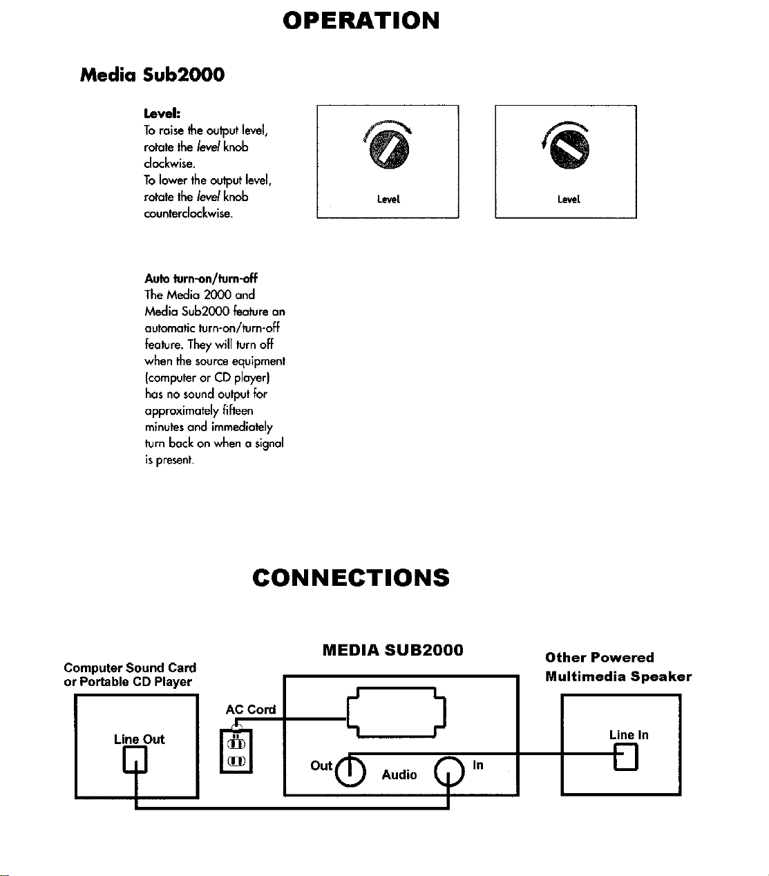
2
Page 5

Service Bulletin
3
Service Bulletin JBL9802 - May 1998 This is considered a Major repair
To: All JBL Service Centers
Model: Media Sub2000 Powered Subwoofer
Subject: False Triggering
In the event you receive a Media Sub2000 with the complaint: “the subwoofer never shuts off”, or “the
unit cycles on & off by itself with no input signal”, perform the following modification to raise the input
threshold of the subwoofer amplifier:
Procedure:
1) Turn the unit upside-down and remove the (8) mounting screws on the bottom plate. This includes the (2)
deeply recessed screws near the center of the plate. Then remove the (2) smaller screws holding the
black input plate to the end of the cabinet.
2) Pull the plate and amplifier up and out the cabinet.
3) Unplug all (3) molex connectors, and remove the (2) small screws holding the input plate onto the
amplifier PCB; remove the input plate.
4) To gain access to the components, remove the (2) remaining small screws holding the PCB to the bottom
plate and detach it from the plate.
5) Locate C351 - 100pf SMD cap. Replace with 470 pf part, (JBL part #CP1885). See drawing.
6) Locate R348 - 330KΩ SMD resistor. Replace with 100kΩ part, (JBL part #RS2043).
7) Locate Diode D351. Solder a 10KΩ resistor (JBL part #RS2042) in parallel with the diode.
8) Reassemble and replace the amplifier assembly into the cabinet in the reverse order , making sure all
connectors and screws are replaced.* When re-attaching the input plate make sure both ground
terminals are attached to the screw.
9) Test unit and assure that the subwoofer stays in the standby mode with no input signal, and comes out of
protection with a 50 Hz, 50 mV input signal.
Model Serial number
120V
Media
Sub2000
Media
Sub2000
AC0029-10001
to
AC0029-11300
AC0029-11301
and above
Serial number
230V
AC0030-01001
and above
* When replacing the final two screws in the
center of the bottom plate, because of the
design you cannot drop the screws into each
cavity and expect the screws to align with the
holes.
With a Philips screwdriver well fitted to the
screw head, you may either use a magnetized
screwdriver and lower the tip (with screw)
carefully down into the cavity to align; OR
turn the subwoofer right-side up and insert the
tip with screw up into the cavity.
Status Action
False Triggering Change value of C351 and R348; add 10K
resistor in parallel with D351
Factory
Modification
NONE REQUIRED
Ω
JBL Incorporated 250 Crossways Park Dr. Woodbury, New York 11797 (516) 496-3400
Page 6

1
4
2
3
4
5
6
7
E
AUDIO INPUTAUDIO INPUT
D
C
AUDIO OUTPUTAUDIO OUTPUT
BLOCK DIAGRAM
B
JK301
JK302
IC301
TL072
VR404
TL074
LOW-PASS
FILTER
AFTER NO SIGNAL I/P FOR A WHILEAFTER NO SIGNAL I/P FOR A WHILE
SMITH TRIGGER COMPARE CIRCUITSMITH TRIGGER COMPARE CIRCUIT
VOL CNTL
AUTO POWER OFF/ONAUTO POWER OFF/ON
IC351
POWER AMP
MUTE
Q501
IC601IC351
TDA8563Q
LD402
MULITI-LED
RED-STANDBY
GREEN-ON
SWITCHING POWERSWITCHING POWER
SUBWOOFER
POWER SUPPLYPOWER SUPPLY
CIRCUIT
E
D
C
B
AC CORDAC CORD
A
Media Sub2000
TL074
T901/D906/IC901
A
1
2
3
4
5
6
7
Page 7

1
5
2
3
4
5
6
7
E
D
C
WIRING DIAGRAM
AUDIO
OUT
IN
AUDIO
E
CN401
R
JK302
L
R
JK301
L
LFA0194-001
MAIN PCB
MAIN PCB
D
CN901CN901
C
1
CN601
B
A
Media Sub2000
SUBWOOFER
AC SOCKETAC SOCKET
1
RB401
+
AC CORDAC CORD
B
A
LVU0195-011
CONTROL PCB
1
2
3
4
5
6
7
Page 8

1
6
2
3
4
5
6
7
E
D
C
CONTROL PCB PRINTED CIRCUIT
B
LD402
T
2-2.0X1.75
VOLUME
1
VR404
T
R476
E
LVU0195-011
D
C
RB401
T
B
A
Media Sub2000
1
2
3
4
5
6
7
A
Page 9

7
Page 10

1
8
2
3
E
4
5
2
6
7
E
D
C
EXPLODED VIEW
B
17
4
19
18
S8
S1
D
17
S9
25
24
S2
12
16
15
7
1
11
17
22
8
P1
3
6
18
S5
13
S6
14
S2
10
C
9
5
B
23
17
A
21
S3
S7
S4
S6
20
A
Media Sub2000
1
2
3
4
5
6
7
Page 11

123
1. GROUND
2. INPUT
3. OUTPUT
1
TDA8563Q
9
2
3
4
5
6
7
8
13
11
10
12
INPUT 2
DIAGNOSTIC OUTPUT
MODE SWITCH
2
VP
OUTPUT 2B
GND2
OUTPUT 2A
OUTPUT 1B
GND1
OUTPUT 1A
VP
1
GROUND (SIGNAL)
INPUT 1
V
OUT
R
L
= 100
Ω
50
Ω
2
3
V
CC
14
PULSE INPUT
TDA8563Q, IC601
DUAL OPAMP,
TL072, IC301
+12V REGULATOR
7812 IC902
PS2501, IC903
TOP227Y, IC901
QUAD OP AMP,
TLO74, IC351
9
Page 12

MECHANICAL PARTS LIST
10
REF# DESCRIPTION PART NO. QTY
1 FRONT CAB ABS W/KNOB HOLEx1 BPF5041-AQ1 1
2 REAR CAB PP BEIGE BPA0029-AQ1 1
3 SPEAKER DRIVER 4" 2 OHM 20W FTF2040-371 1
4 BAFFLE MAGIC WOOF BPA0030-001 1
5 BOTTOM MAGIC WOOF BPB0023-001 1
6 PORT PLATE t=3.0 mm GAL0089-002 1
7 SEAL RUBBER BRB0010-001 1
8 RUBBER BRB0009-001 1
9 MAIN ASSEMBLY APE0194-002 1
10 HEAT SINK GAL0090-001 11
11 PORT EDGE BPR0033-001 1
12 REAR BRACKET GSE0181-002 1
13 PCB BRACKET GSE0180-001 1
14 LED PCB ASSEMBLY APE0195-012 1
15 TIN FOIL 0.1 TIN+0.4 PAPER GTN0034-001 1
16 PVC PLATE L20.0xW6.0xT0.5 mm BNP0052-001 3
17 MASK PLATE MAGIC WOOF (M.SUB) BPA0031-AQ0 12
18 RUBBER BRB0008-001 2
19 BUSHION BOSS BUSHION BRB0014-001 6
20 FEET BRF0024-001 4
21 LENS BPN0066-001 1
22 LOGO PLATE LOGO PLATE BPL0018-002 1
23 KNOB MEDIA SUB BPK5041-AQ0 1
24 AC SOCKET 2.5A~250V UL/CSA/VDE CPP0002-004 1
25 LINE CORD VDE 1830 MM 2559-002222 1
P1 DRIVER SPONGE OD102xID91xT1 IVE0043-002 1
S1 SCREW M4x0.7PxL85.0 mm H060501-185 6
S2 SCREW T3.0x1.27P-2RHxL8 mm H101001-108 3
S3 SCREW T3.0xL8.0 mm H101001-308 2
S4 SCREW T3.0xL16.0 mm H101001-316 4
S5 SCREW T3.0xL10.0 H101002-310 4
S6 SCREW M3x0.5Px8 mm H120301-308 2
S7 SCREW M3x0.5Px10 mm H120301-310 2
S8 SCREW M3x0.5PxL8.0 mm H120308-308 2
S9 SCREW T3.0xL10.0 mm H101001-110 1
Page 13

MEDIA SUB2000 ELECTRICAL PARTS LIST
11
DESIGNATOR DESCRIPTION PART # QTY
CAPACITORS
C301,C302 CHIP CAP 220 pF 50V 10% PCV5645-221
C303,C304,C352,C612 CHIP CAP 1 uF 16V +80-20% PCV3962-105
C350,C353,C905,C909,
C911-C915,C930
C351 CHIP CAP 470 pF 50V 10% PCV5645-471
C354 COND ELECT 330 uF 16V 20% PRE3952-331
C355,C910 COND ELECT 100 uF 16V 20% PRE3952-101
C504,C505,C608 CHIP CAP 4.7 uF 16V +80-20% PCV3962-475
C600,C603,C605 CHIP CAP 0.068 uF 50V 5% PCV5635-683
C604 CHIP CAP 0.15 uF 50V 10% PCV3945-154
C606 CHIP CAP 0.022 uF 50V 10% PCV5645-223
C609 CHIP CAP 0.001 uF 50V 10% PCV5645-102
C610 CHIP CAP 0.22 uF 50V +80-20% PCV3965-224
C901 COND SAFTY 0.1 uF 250V 20% PVS3559-104
C902 COND ELECT 150 uF 400V 20% PJE995E-151
C903 COND ELECT 47 uF 25V 20% PRE3953-470
C907 COND ELECT 2700 uF 25V 20% PVR9953-272
C908 COND ELECT 1000 uF 25V 20% D=10 PVE3953-102
C916 COND ELECT 22 uF 25V 20% PRE3953-220
C917,C918 COND SAFTY 0.0022 uF 250V 20% PVS3559-222
C919,C920 COND SAFTY 0.001 uF 250V 20% PVS3559-102
CHIP CAP 0.1 uF 50V 20% PCV3955-104
2
4
10
1
1
2
3
3
1
1
1
1
1
1
1
1
1
1
2
2
CONNECTORS
CN401 CONNECTOR J.S.T. 2.0mm PH CCN7879-026
CN601 CONNECTOR 2 PIN CL3962WVO CCN3962-002
CN901 CONNECTOR 4 PIN CL3962WVO CCN3962-234
SEMICONDUCTORS
D351,D903,D905 DIODE SW LL4148 TELEFUNKEN RCD4148-001
D902 DIODE BYV26D PHILIPS RAD0026-001
D906 DIODE MBR/STPS20100CT RHD2010-001
ZD903 DIODE P6KE180A RHD0180-001
ZD904 DIODE ZENR 13.5-14.0V .5W RAZ0859-083
ZD908 DIODE ZENR 12.6-13.1V .5W RAZ0859-082
IC301 IC 8 PIN TL072 DUAL OP-AMP RCI0720-001
IC351 IC 14 PIN TL074CD QUAD OP-AMP RCI0740-001
IC601 IC 13 PIN TDA8563Q POWER AMP RHI8563-001
BD901 RECTIFIER BRIDGE RS204L RHD0204-001
IC901 IC 3 PIN TOP227Y PWM SWITCH RHI0227-001
IC902 IC 3 PIN REGULATOR +12V RHI7812-004
IC903 IC 4 PIN PS2501 OPTOCOUPLER RHI2501-001
Q352,Q353,Q501,Q901 XISTR NPN SMT TYPE (2SC945) RCN1623-001
RESISTORS
R301,R305,R353,R354,R357,R358, CHIP RES. 10K OHM 1/8W 5% QCF0851-103
R503,R607,R905,R906
R303 CHIP RES. 5.6K OHM 1/8W 5% QCF0851-562
R348 CHIP RES. 100K OHM 1/8W 5% QCF0851-104
R351,R370,R610 CHIP RES. 100 OHM 1/8W 5% QCF0851-101
R355,R356 CHIP RES. 150K OHM 1/8W 5% QCF0851-154
R359 CHIP RES. 330K OHM 1/8W 5% QCF0851-334
1
1
1
3
1
1
1
1
1
1
1
1
1
1
1
1
4
11
1
1
3
2
1
Page 14

ELECTRICAL PARTS LIST (CONT'D)
12
DESIGNATOR DESCRIPTION PART # QTY
R360,R606 CHIP RES. 220K OHM 1/8W 5% QCF0851-224
R361 CHIP RES. 820K OHM 1/8W 5% QCF0851-824
R362,R380 CHIP RES. 680K OHM 1/8W 5% QCF0851-684
R363 CHIP RES. 82K OHM 1/8W 5% QCF0851-823
R364,R615 CHIP RES. 470 OHM 1/8W 5% QCF0851-471
R366,R368,R614 CHIP RES. 1K OHM 1/8W 5% QCF0851-102
R369 CHIP RES. 680 OHM 1/8W 5% QCF0851-681
R501,R907 CHIP RES. 22K OHM 1/8W 5% QCF0851-223
R502 CHIP RES. 33K OHM 1/8W 5% QCF0851-333
R604 CHIP RES. 12K OHM 1/8W 5% QCF0851-123
R605 CHIP RES. 910 OHM 1/8W 5% QCF0851-911
R616 CHIP RES. 330 OHM 1/8W 5% QCF0851-331
R901 RESISTOR 1M OHM 1/2W 5% QHF0250-105
R902 CHIP RES. 22 OHM 1/8W 5% QCF0851-220
R903,R904 CHIP RES. 33 OHM 1/8W 5% QCF0851-330
BETWEEN Q352 BASS TO GND RESISTOR 10K OHM 1/8W 5% QAF0850-103
MISCELLANEOUS
IC601 TO HSINK SCREW M3.0xL12.0xP0.5 mm H120302-312
IC901 HEAT SINK AL 30x25x35H BLACK GAL0093-001
JK301,JK301 PHONE JACK JYE TAI 3542-01-030 CJM9380-028
CN601 TO WOOFER SPK CON/WIRE 2 COND 400/350mm 4999A-369
CN901 TO AC SOCKET CON/WIRE 4 COND 180mm P=3.96m 4999A-370
D906 HEAT SINK AL 2.0t BLACK GAL0094-001
D906 NUT M3.0x2.5t NICKEL HNM3055-125
D906,IC901 WASHER HD=6.7 ID=3.2 OD=3.6 DSS0007-001
D906,IC901 SI RUBBER 13x18x0.3t mm GSI0001-001
F901 FUSE 4A 250V SLOW KSD2400-001
HEAT SINK TO IC901 SCREW T3x6 mm H101012-206
HSINK TO D906 SCREW M3.0x0.5PxL8.0 mm H060308-108
L901 AC FILTER A6109 33 mH/0.4A JLF0002-001
L902 CHOKE 6110 3.3 uH SVC0002-339
P1 TO P2 WIRE 18 GA 80 MM BLACK UL 1617 5824-080BB
PCB TO H/SINK(IC901) SCREW T3.0xL6.0 mm H120301-106
T901 PWR TRANS 97-550-1 EE-30 TSA1201-001
2
1
2
1
2
3
1
2
1
1
1
1
1
1
2
1
2
1
2
1
1
1
1
2
2
1
1
1
1
1
1
1
1
LED PCB ASSEMBLY PARTS LIST
REF. NO DESCRIPTION PART NO QTY
LD402 LED MULTI-COLOR LED TWO KEM0001-001
PCB BRACKET FELT 120x5x0.2 mm IVS0005-001
R476 RESISTOR 5K OHM 1/6W 5% CF QAF0650-502
RB401 TO CN401 CON/WIRE 6 COND 200 mm 4999A-384
VR404 CNTL ROTRY RV093NB10KPtEj-15F(S MRR0103-012
94V0 PCB LED PCB LVU0195-201
1
1
1
1
1
1
Page 15

Media Sub2000
13
SCHEMATIC
A
B
C
D
E
F
G
H
I
J
K
L
M
N
O
LFA0194-002
1
R604
220P
220P
R301
10K
C301
C302
R303
5K6
R305
10K
C600
.068
12K
C603
.068
R616
330
JK301
INPUT
2
JK302
OUTPUT
3
1/50
R605
2
3
R606
220k
IC301/B
910
C602
OTP
TL074
IC351/A
C350
.1
7
4
11
8
TL072
4
.022
C606
1
C605
R351
100
5
6
R607 C604
10K
4
C304
C303
10K
10K 1/50
C351
100P
R353
R354
R348
5
6
330K
2
TL072
3
IC301/A
1
C352
1/50
R356 R358
150K 10K
R355
150K
9
10
R357
10K
TL074
IC351/C
R359
330K
8
0.1/50
D351
1N4148
+
C353
Q352
2SC945
R360
+
220K
C354
330/16
C355
100/16
+
R361
820K
R363
82K
.068
R906
10K
R608
R362
680K
13
12
R610
100
.15
10K
C915
.1
R370
IC351/D
TL074
R380
680K
6
5
100
TL074
IC351/B
C612
1/50
R905
10K
+
C910
100/16
14
R615
4K7
R366
7
1K
R369
680
R364
470
C608
4.7/16
C609
.001
R614
1K
R368
1K
Q353
2SC945
TDA8563Q
IC601
VP1
GND(S)
IN 1IN 1
OUT1A
OUT1B
GND 1GND 1
OUT2A
GND 2GND 2
OUT2B
VP2
MODE
VDIAG
13121110981 2 3 4 5 6 7
IN 2IN 2
12
SUBWOOFER
1
2
CN601
C905
DC-
150/400
IC901
TOP227
2
C918
.0022_Y2
.1
Q901
2SC945P
+
C916
22/16
RS204L
DC+
C902
1
3
R907
22K
+
22
R902
.1
C913
.1
C914
ZD903
P6KE180
D902
BYV26D
1N4148
D903
47/25
TSA1201-001
1
3
5
6
+
C903
C917
.0022_Y2
C911
.1
T901BD901
R904
33
12
8
X
11
7
ZD908
D905
3
O
2
G
IC902
78L12
D906
SPS20100CT
2
3
1
PS2501
IC903
21
3
4
13V
1N4148
1
I
.1
C912
13V
R903
33
ZD904
C909
.1
L902
3.3uH/2.5A
+
C907
2700/25
1000/25
+
C908
3
4
5
6
R501
22K
C610
0.22
Q501
2SC945P
R503
123456
CN401
AC INLET
AC INLET
10K
L901
33mH/0.4A
!
C505
4.7/16
.001_Y1
.001_Y1
0.1/250
R901
1M_1/2W
F901
4A
C919
C920
1 2
C901
CN901
12
C504
4.7/16
3 4
R502
33K
7
8
9
REMARK:
VOLUME CNTL & POWER INDICATOR LEDVOLUME CNTL & POWER INDICATOR LED
123456
RB401
R476
5K
VOL
LD402
VR404
10K
LVU0195-011
A
B
C
D
E
F
G
H
I
J
K
L
M
N
O
7
8
9
Page 16

E
14
D
1
2
6
7
2
3
8
4
ITEM NAMENAME PART NO.
2
3
4
5
6
7
8
5
MEDIASYS SUB.MEDIASYS SUB. AFA0078-001AFA0078-0011
POLY BAG
END CAPEND CAP ITF0135-001ITF0135-001
GIFT BOX
CARTON
OWN MANUAL
OWN MANUAL
POLY BAG
6
IVP0001-040
ICG0016-001ICG0016-001
ICC0129-002
YOM0145-001YOM0145-001
YWC0009-002YWC0009-002WARRANTY CARD
IVP0001-018
7
E
D
04
PE-LD
3
C
PACKING EXPLODED VIEW
B
A
Media Sub2000
1
4
3
5
B
A
C
1
2
3
4
5
6
7
 Loading...