

Page 1
English
NORTHRIDGE™E SERIES
E150P, E250P (230V)
OWNER’S GUIDE
®
Page 2
READ FIRST!
English
CAUTION
RISK OF ELECTRIC SHOCK
DO NOT OPEN
CAUTION: To prevent electric shock,
do not remove the grounding plug
on the power cord, or use any plug
or extension cord that does not have
a grounding plug provided.
Make certain that the
AC outlet is properly grounded.
Do not use an adapter plug
with this product.
The lightning flash with arrowhead symbol,
within an equilateral triangle, is intended to
alert the user to the presence of uninsulated
“dangerous voltage” within the product’s
enclosure that may be of sufficient magnitude to constitute a
risk of electric shock to persons.
The exclamation point within an equilateral
triangle is intended to alert the user to the
presence of important operating and
maintenance (servicing) instructions in the
literature accompanying the appliance.
1. Read Instructions. All the safety and
operating instructions should be read
before the product is operated.
2. Retain Instructions. The safety and operating instructions should be retained for
future reference.
3. Heed Warnings. All warnings on the
product and in the operating instructions
should be adhered to.
4. Follow Instructions. All operating and
use instructions should be followed.
5. Water and Moisture. The product should
not be used near water – for example, near
a bathtub, washbowl, kitchen sink, laundry
tub, in a wet basement, or near a swimming
pool, and the like.
6. Accessories. Do not place this product
on an unstable cart, stand, tripod, bracket,
or table. The product may fall, causing serious injury to a child or adult, and serious
damage to the product. Use only with a
cart, stand, tripod, bracket, or table recommended by the manufacturer, or sold with
the product. Any mounting of the product
should follow the manufacturer’s instructions, and should use a mounting accessory recommended by the manufacturer.
7. Wall or Ceiling Mounting. The product
should be mounted on a wall or ceiling
only when and as recommended by the
manufacturer.
Important Safety Precautions!
8. Ventilation. Slots and openings in the
cabinet are provided for ventilation and to
ensure reliable operation of the product
and to protect it from overheating, and these
openings must not be blocked or covered.
The openings should never be blocked by
placing the product on a bed, sofa, rug, or
other similar surface. This product should
not be placed in a built-in installation such
as a bookcase or rack unless proper ventilation is provided or the manufacturer’s
instructions have been adhered to.
9. Heat. The product should be situated
away from heat sources such as radiators, heat registers, stoves, or other products that produce heat. If placed near an
amplifier, check with the manufacturer for
applicability.
10. Power Sources. This product should be
operated only from the type of power
source indicated on the marking label. If
you are not sure of the type of power supply to your home, consult your product
dealer or local power company. For products intended to operate from battery
power, or other sources, refer to the operating instructions.
11. Grounding or Polarization.
may be equipped with a
This product
polarized alternating
plug having one blade wider than the
other). This plug will fit into the power outlet only one way. This is a safety feature. If
you are unable to insert the plug fully into
the outlet, try reversing the plug. If the plug
should still fail to fit, contact your electrician to replace your obsolete outlet. Do not
defeat the safety purpose of the polarized
plug.
12. Power-Cord Protection.
Power-supply cords should be routed so
that they are not likely to be walked on or
pinched by items placed upon or against
them, paying particular attention to cords at
plugs, convenience receptacles, and the
point where they exit from the product.
13. Cleaning. Unplug this product from the
wall outlet before cleaning. Do not use liquid cleaners or aerosol cleaners. Use a
damp cloth for cleaning.
14. Nonuse Periods. The power cord of the
product should be unplugged from the outlet when left unused for long periods of
time.
15. Lightning. For added protection for this
product during a lightning storm, or when it
is left unattended and unused for long periods of time, unplug it from the wall outlet
and disconnect the antenna or cable system. This will prevent damage to the product due to lightning and power-line surges.
16. Overloading. Do not overload wall outlets, extension cords, or integral convenience receptacles, as this can result in a
risk of fire or electric shock.
-current line plug (a
17. Object and Liquid Entry. Never push
objects of any kind into this product
through openings, as they may touch dangerous voltage points or short-out parts
that could result in a fire or electric shock.
Never spill liquid of any kind on the product.
18. Damage Requiring Service. Unplug this
product from the wall outlet and refer servicing to qualified service personnel under
the following conditions:
a. The power-supply cord or the plug has
been damaged; or
b. Objects have fallen, or liquid has been
spilled into, the product; or
c. The product has been exposed to rain or
water; or
d. The product does not operate normally
when following the operating instructions.
Adjust only those controls that are covered
by the operating instructions, as an
improper adjustment of other controls may
result in damage and will often require
extensive work by a qualified technician to
restore the product to its normal operation;
or
e. The product has been dropped, or the
enclosure damaged; or
f. The product does not appear to operate
normally or exhibits a marked change in
performance.
19. Attachments. Do not use attachments
not recommended by the product manufacturer, as they may cause hazards.
20. Replacement Parts. When replacement
parts are required, be sure the service
technician has used replacement parts
specified by the manufacturer or that have
the same characteristics as the original
part. Unauthorized substitutions may result
in fire, electric shock or other hazards.
21. Safety Check. Upon completion of any
service or repairs to this product, ask the
service technician to perform safety
checks to determine that the product is in
proper operating condition.
22. Servicing. Do not attempt to service this
product yourself, as opening or removing
covers may expose you to dangerous
voltage or other hazards. Refer all servicing
to qualified service personnel.
Page 3
SPEAKER PLACEMENT
• As a general rule, bass
response increases as a subwoofer is placed closer to a
wall. Therefore, bass output is
maximized when the subwoofer is placed in a corner.
• It is also recommended that
the subwoofer be positioned
along the same wall as the
front loudspeakers.
Low-frequency sounds are normally omnidirectional, meaning
the listener can’t tell where they
are generated from. However,
frequencies between 75Hz –
150Hz can be localized, especially at higher volume levels.
Positioning your subwoofer as
recommended will provide the
most natural soundstage and
imaging from your loudspeaker
system.
Remember that these are just
guidelines. Since every listening
room is different, JBL strongly
recommends experimenting
SPEAKER CONNECTION
When we designed the E150P
and E250P powered subwoofers, our goal was to offer
the user the best possible performance combined with the
most flexible and complete
installation options. Please look
over the following three examples to determine which
description best matches your
system and follow the corresponding hookup instructions.
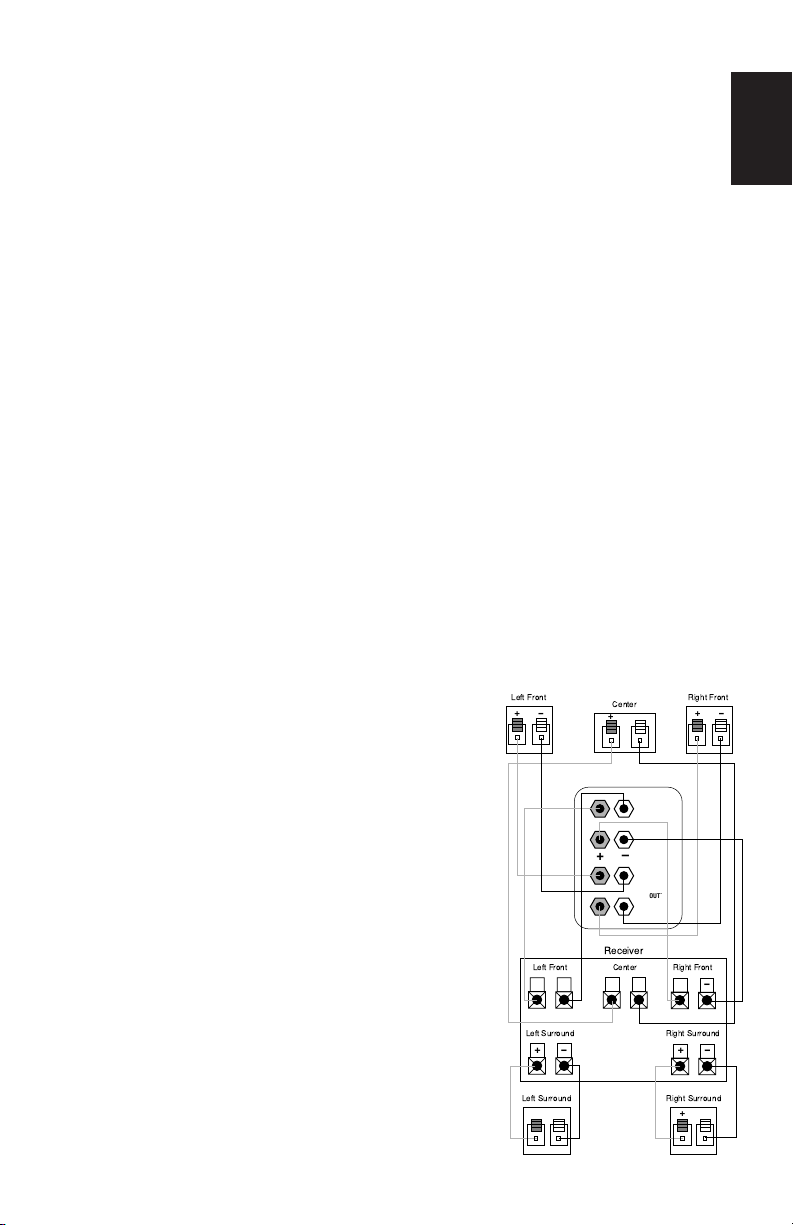
ANALOG RECEIVER/PROCESSOR –
SPEAKER LEVEL CONNECTIONS
Use this installation method
with an analog receiver/
processor that does not have
digital processing or bass
management, and also does not
have a subwoofer output or a
volume-controlled preamp
(line-) level output:
Connect your receiver or amplifier’s front left and right speaker
terminals to the left and right
terminals on the subwoofer that
are marked “High Level In.”
Connect the left and right terminals on the subwoofer that are
marked “High Level Out” to the
cor-responding terminals on the
back of your front left and right
speakers.
To use the binding-post speaker
terminals with bare wire,
unscrew the collar until the hole
through the center post is visible under the collar. Insert the
bare end of the wire through the
hole in the post, then screw the
collar back down until the connection is tight. The holes in the
center of the collars are
intended for banana-type connectors.
Connect your receiver or amplifier’s center, left and right surround-speaker terminals to the
corre-sponding terminals on the
back of your center, left and
right surround speakers.
with the positioning of your subwoofer to obtain the most pleasing results in your room. One
technique that can help you find
the ideal subwoofer location is
to temporarily place the subwoofer near the main listening
location. Then move around the
room and determine where you
hear the most pleasing bass
performance. This would then
be the ideal location for the subwoofer.
To comply with European CE
certification, these holes are
blocked with plastic inserts at
the point of manufacture.To use
banana-type connectors
requires the removal of the
inserts. Do not remove these
inserts if you are using the
product in an area covered by
the European CE certification.
LEVEL
LEVEL
L
L
HIGH
IN
R
R
L
HIGH
OUT`
R
Right Front
+ –
Right Front
+ –
Right Surround
+ –
Right SurroundLeft Surround
+ –
Left Front
+ –
Left Front Center
+ – + –
Left Surround
+ –
+ –
Center
+ –
Subwoofer
+ –
Receiver
English
Page 4

ANALOG RECEIVER/PROCESSOR –
CROSSOVER
FREQUENCY
LEVEL
LINE LEVEL IN
PHASE
Min
Max
L R
LFE NORMAL
HIGH
LEVEL
IN
L
R
HIGH
LEVEL
OUT
+ –
50Hz
0º 180º
150Hz
Subwoofer
Out
RECEIVER
L
R
For LFE use L or R
L R
LINE LEVEL CONNECTIONS
English
Use this installation method with
an analog receiver/
processor that does not have
digital processing or bass
management, and is equipped
with a full-range subwoofer output or a volume-controlled preamp (line-) level output:
Use RCA-type patch cords
to connect the line-level subwoofer outputs on your receiver
or amplifier to the line-level
inputs on the subwoofer.
IMPORTANT: Make sure that the
LFE toggle switch on the
subwoofer is in the “Normal”
position. Do not use the “LFE”
position with Dolby Pro Logiconly processors.
Note: If your receiver or amplifier has only one subwoofer output jack, then you may connect
the subwoofer output on your
receiver/preamplifier to either
the left or right line-level input
on the subwoofer. It makes no
difference which jack you
choose.
Connect each speaker to the
corresponding speaker
terminals on your receiver or
amplifier.
Make sure your receiver or
processor is configured correctly: Make sure that the subwoofer is configured as “On.”
Note for advanced users: If your
receiver/processor has
a built-in low-pass crossover
filter for the subwoofer output,
then the LFE switch should be
set to the “LFE” position to
bypass the subwoofer’s internal
crossover.
Page 5

DIGITAL RECEIVER/PROCESSOR –
CROSSOVER
FREQUENCY
LEVEL
LINE LEVEL IN
PHASE
Min
Max
L R
LFE NORMAL
HIGH
LEVEL
IN
L
R
HIGH
LEVEL
OUT
+ –
50Hz
0º 180º
150Hz
Subwoofer
Output/LFE
RECEIVER/PREAMPLIFIER
L
R
For LFE use L or R
LFE CONNECTION
Use this installation method for
Dolby Digital, DTS®or other digital surround processors that
have bass-management
programming, or for analog
receivers/processors that have
a filtered subwoofer output:
IMPORTANT: Make sure that the
LFE toggle switch on the subwoofer is in the “LFE” position.
Use the line-level input jacks for
the Low-Frequency Effects
channel. Connect these jacks to
the LFE output or subwoofer
output on your receiver or
amplifier.
Note: If your receiver or amplifier has only one subwoofer output jack, then you may connect
the subwoofer output on your
receiver/preamplifier to either
the left or right line-level input
on the subwoofer. It makes no
difference which jack you
choose.
Connect each speaker to the
corresponding speaker terminals on your receiver or amplifier.
Make sure that you have configured your surround-sound
processor for “Subwoofer On”
or “LFE On.” The front left, front
right, center and rear speakers
should be set to “Small” or
“Large” depending on their size
and frequency response.
Consult your receiver’s or
processor’s owner’s manual.
English
Page 6

OPERATION
Northridge E Series
CAUTION
RISK OF ELECTRIC SHOCK
DO NOT OPEN
CROSSOVER
FREQUENCY
LEVEL
LINE LEVEL IN
PHASE
Min
Max
L
R
L R
For LFE use L or R
LFE NORMAL
HIGH
LEVEL
IN
L
R
HIGH
LEVEL
OUT
+ –
50Hz
0º 180º
150Hz
POWER
ON OFF
English
POWER
When the unit is plugged in and
the power switch is on and no
signal is received, the LEDs on
the front of the unit will turn red.
When a signal is present, the
LEDs will turn green.
Note: It will take several minutes for the LEDs to turn from
green to red after the input signal to the subwoofer is
removed. Due to JBL’s unique,
high-output, high-efficiency
amplifier design, power consumption is minimal when the
subwoofer is not receiving a
signal. Of course, the subwoofer
can be turned off, whenever
LEVEL CONTROL
The subwoofer Level Control
adjusts the volume of the
subwoofer relative to the rest of
the system. Proper level adjustment depends on several vari-
woofer placement, type of main
speakers and listener position.
Adjust the subwoofer level so
that the volume of the bass
information is pleasing to you.
ables such as room size, sub-
CROSSOVER ADJUSTMENTS
The Crossover Frequency
Control determines the highest
frequency at which the sub-
This control is not used when
the LFE switch is in the “LFE”
position.
woofer reproduces sounds. If
your main speakers can comfortably reproduce some lowfrequency sounds, set this control to a lower frequency setting,
between 50Hz – 100Hz. This will
concentrate the subwoofer’s
efforts on the ultradeep bass
sounds required by today’s films
and music. If you are using
smaller bookshelf speakers that
do not extend to the lower bass
frequencies, set the low-pass
crossover control to a higher
setting, between 120Hz – 150Hz.
desired, if you do not wish
to leave it in auto (standby)
mode.
Page 7

PHASE CONTROL
English
The Phase Control determines
whether the subwoofer’s piston-like action moves in and out
in phase with the main speakers or opposite the main speakers. There is no correct or
incorrect setting. Proper phase
adjustment depends on several
variables such as subwoofer
placement and listener position.
Adjust the phase switch to
maximize bass output at the listening position.
Remember, every system, room
and listener is different. There
are no right or wrong settings;
this switch offers the added
flexibility to adjust your subwoofer for optimum performance for your specific listening
conditions without having to
move your speakers. If at some
time in the future you happen to
rearrange your listening room
and move your speakers, you
should experiment with the
TROUBLESHOOTING
If you used the high-level
(speaker) inputs and there is no
sound from any of the speakers:
• Check that receiver/amplifier
is on and a source is playing.
• Check that powered
subwoofer is plugged into
an active electrical outlet
and is switched on.
• Check all wires and connections between receiver/
amplifier and speakers. Make
sure all wires are connected.
Make sure none of the speaker
wires are frayed, cut or
punctured.
• Review proper operation
of your receiver/amplifier.
If there is low (or no) bass
output:
• Make sure the connections to
the left and right “Speaker
Inputs” have the correct
polarity (+ and –).
• Make sure that the subwoofer
is plugged into an active electrical outlet and switched on.
• Adjust the crossover point.
• Flip the Phase Control switch
to the opposite position.
• If you are using a Dolby
Digital/DTS receiver or
processor, make sure that the
subwoofer adjustments on
the receiver/processor are
set up correctly.
• Slowly turn the Level
Control clockwise until you
begin to hear the desired
amount of bass.
phase switch in both positions,
and leave it in the position that
maximizes bass performance.
If you used the line-level inputs
and there is no sound from the
subwoofer:
• Check that receiver/amplifier
is on and a source is playing.
• Check that powered subwoofer is plugged into an active
electrical outlet and is switched
on.
• Check all wires and connections between receiver/
amplifier and subwoofer. Make
sure all wires are connected.
Make sure none of the wires
are frayed, cut or punctured.
• Review proper operation of
your receiver/amplifier.
• Slowly turn the Level
Control clockwise until you
begin to hear the desired
amount of bass.
• Make sure that you have configured your receiver/processor
so that the subwoofer/LFE output is on.
Page 8

SPECIFICATIONS
English
E150P E250P
Amplifier
Power (RMS): 150 Watts 250 Watts
Driver: 250mm (10") PolyPlas™ 300mm (12") PolyPlas™
Inputs: Line Level (switchable to LFE) Line Level (switchable to LFE)
and Speaker Level with and Speaker Level with
5-way binding posts 5-way binding posts
Outputs: Speaker Level, High-Pass with Speaker Level, High-Pass with
5-way binding posts 5-way binding posts
Low-Pass
Frequency: Continuously variable Continuously variable
from 50Hz – 150Hz from 50Hz – 150Hz
High-Pass
Frequency: 150Hz when using 150Hz when using
speaker-level output speaker-level outputs
Frequency
Response: 27Hz – low-pass 25Hz – low-pass
crossover setting crossover setting
Dimensions
(H x W x D): 450mm x 309mm x 384mm 500mm x 365mm x 435mm
Weight: 15.5kg 20.1kg
Declaration of Conformity
We, Harman Consumer International
2, route de Tours
72500 Chateau-du-Loir
France
declare in own responsibility, that the products described in
this owner’s manual are in compliance with technical standards:
EN 60065:1998
EN 55013:A14/1999
EN 55020/A14:1999
EN 61000-3-2/A14:1999
EN 61000-3-3/1.1995
PRO SOUND COMES HOME
JBL Consumer Products, 250 Crossways Park Drive, Woodbury, NY 11797
8500 Balboa Boulevard, Northridge, CA 91329
2, route de Tours, 72500 Chateau-du-Loir, France
800.336.4JBL (4525) (USA only) www.jbl.com
© 2003 Harman International Industries, Incorporated
JBL is a registered trademark of Harman International Industries, Incorporated.
Gary Mardell
Harman Consumer International
Chateau-du-Loir, France 2/03
Part No.
™
351248-001
* Trademark of Dolby Laboratories.
DTS is a registered trademark of Digital Theater Systems, Inc.
All features and specifications are subject to change
without notice.
All dimensions include grilles and feet.
 Loading...