

Page 1
CVR700
HIGH-PERFORMANCE
A
UDIO/VIDEO RECEIVER/VIDEO
PROCESSOR/OPTICAL DISC
CHANGER
CVPD50
50-INCH HIGH-DEFINITION
P
LASMA DISPLAY
®
JBL CINEMA VISION™SYSTEM
OWNER’S GUIDE
Page 2

JBL CINEMA VISION™SYSTEM: CVPD50 HIGH-DEFINITION PLASMA
DISPLAY AND CVR700 CONTROL CENTER WITH AUDIO/VIDEO
RECEIVER, VIDEO PROCESSOR AND OPTICAL DISC CHANGER
4 Important Safety Precautions
5 Introduction
7 Safety Information
10 What’s Included
Disc Formats Supported by This Player
12
13 Terminology
CVR700 Front-Panel Controls
16
19 CVR700 Front-Panel Information Display
20 CVR700 Rear-Panel Connections
24 CVR700R2 Remote Control Functions
32 CVR700R1 Remote Control Functions
Installing and Connecting the Equipment
39
39 Recommended Placement
39 Wall-Mounting the CVPD50 Plasma Display
39 Installing the CVPD50 Plasma Display on the Included
Credenza Stand
40 Important Safety Notes
40 Important Information About the CVPD50 Plasma Display
42 Basic Installation
45 System Configuration
46 Source Configuration
48 Speaker Configuration
48 Configuring Speaker Sizes
49 Speaker Crossover Configuration
50 Speaker Distances
50 Output Level Adjustment
51 Using EzSet
51 Manual Output Level Adjustment
52 Advanced Settings
52 Front-Panel Brightness
52 Volume Default
53 Main Menu Timeout
53 Fan Speed
53 Lip Sync
53 DVD Setup
54
Parental Control
55 Screen Setup
55 Inputs and Picture-in-Picture Settings
56
Picture Settings
57 Display Settings
57
Advanced Settings Menu
58 4:3 Scaling
58 Information Menu
Basic Operation
59
59 Turning the CVR700 and CVPD50 On or Off
59 Source Selection
59 Volume Control
60 Surround Mode Selection
Digital Audio Playback
60
60
Dolby Digital
60 DTS
61 Selecting a Digital Source
61 Digital Bitstream and Surround Mode Indicators
61
PCM Playback
61 Speaker/Channel Indicators
62 Audio Surround Mode Chart
63 Night Mode
63 MP3 and WMA Compressed-Audio Playback
64 Tuner Operation
64 Station Selection
64
Preset Tuning
64 Recording
64
Output Level Trim Adjustment
65 Memory Backup
66 Optical Disc Changer Playback Basics
66 Loading Discs
66 Status Bar
Selecting a Disc for Playback
67
67 JBL On Screen Library
™
68 Transport Controls – Playing a Disc
68 Random Play
69 Repeat Play
69 Repeat A-B
70 DVD Playback
70 Using a DVD’s Menu
70 Notes on DVD-Audio Discs
70 Zoom Feature
71 CD Playback
71 Audio CD Playback Features
71 Selecting a Track
71 CD Status Bar
71 Video Off Feature
72 MP3/WMA Playback
72 MP3 or WMA Disc Playback
73 JPEG Playback
74 VCD Playback
74 Using the Status Bar for VCD Playback
74 Playback Control
75 Programmed Play
76 Programming the CVR700R2 Remote
Programming Product Codes
76
76 Preprogrammed Code Entry
77 Automatic Code Entry
78 Learning Commands
79 Changing Devices
Macro Programming
80
81 Recording a Macro
81 Preprogrammed Macros
82 Erasing a Macro
82 Read a Macro
Punch-Through Configuration
83
83 Volume Punch-Through
83 Channel Control Punch-Through
84 Transport Control Punch-Through
84 EzSet Configuration
Renaming
85
85 Renaming a Device
86
Renaming Individual Buttons
87 Resetting the Remote
88 Programmed Device Functions
CVR700R2 Remote Function List T
89
able
92 Programming the CVR700R1 Remote
Page 3

92 Programming Product Codes
3637383940
41
44454647484950515253545556
57
38
39
40
41
25
26
27
28
29
30
24
23
22
21
20
31
37
36
35
34
33
32
31
37
36
35
34
33
32
48
49
50
51
47
46
45
44
43
42
1 2 3 4 5
6
The exclamation point within an equilateral
triangle is intended to alert the user to the
presence of important operating and
maintenance (servicing) instructions in the
literature accompanying the appliance.
CAUTION: To reduce the risk of electric shock,
do not remove cover (or back).
No user-serviceable parts inside.
Refer servicing to qualified service personnel.
CAUTION: To prevent electric shock,
do not use this (polarized) plug with
an extension cord, receptacle or other outlet
unless the blades can be fully inserted to
prevent blade exposure.
The lightning flash with arrowhead symbol,
within an equilateral triangle, is intended to
alert the user to the presence of uninsulated
“dangerous voltage” within the product’s
enclosure that may be of sufficient magnitude to constitute
a risk of electric shock to persons.
92 Direct Code Entry
92
Auto Search Method
93 Learning Codes
93
Erasing Learned Codes
93 Macros
94 Programmed Device Functions
94 Volume Punch-Through
95 Channel Control Punch-Through
Transport Control Punch-Through
95
95 Resetting the Remote Memory
96 CVR700R1 Remote Function List Table
98 CVR700R1 Remote Setup Code Tables
109 Troubleshooting Guide
110 System Reset
111 Technical Specifications
113 Index
See trademark acknowledgements on page 114.
Typographical Conventions
In order to help you use this manual with the remote controls, front-panel controls and
-panel connections, certain conventions have been used.
rear
EXAMPLE – (bold type) indicates a specific remote control or front-panel button or
indicator, or rear-panel connection jack
EXAMPLE – (OCR type) indicates a message that is visible on the front-panel
information display or screen
EXAMPLE – (Synchro type) indicates a message that is visible on the CVR700R2
remote’s LCD display
1 – (number in a square) indicates a specific front-panel control
a – (number in an oval) indicates a button or indicator on the CVR700R2 remote
control
¡ – (number in a circle) indicates a rear-panel connection
A – (letter in a square) indicates an indicator in the front-panel information display
– (number in a triangle) indicates a button or an indicator on the CVR700R1 remote
control
3
Page 4
read first!
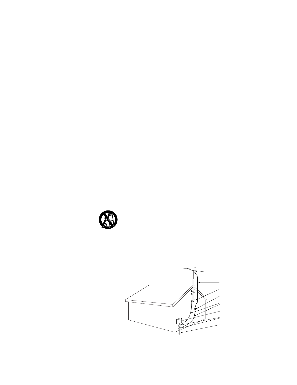
Antenna Lead-In Wire
Ground Clamp
Antenna Discharge Unit (NEC Section 810-20)
Grounding Conductors (NEC Section 810-21)
Electric Service Equipment
Ground Clamps
Power Service Grounding Electrode System
(NEC Art. 250, Part H)
Important Safety Precautions!
1. Read these instructions.
2. Keep these instructions.
3. Heed all warnings.
4. Follow all instructions.
5. Do not use this apparatus near water.
6. Clean only with a dry cloth.
7. Do not block any ventilation openings.
Install in accordance with the manufacturer’s instructions.
8. Do not install near any heat sources
such as radiators, heat registers, stoves
or other apparatus (including amplifiers)
that produce heat.
9. Do not defeat the safety purpose of
the polarized or grounding-type plug.
A polarized plug has two blades with one
wider than the other. A grounding-type
plug has two blades and a third grounding prong. The wide blade or the third
prong are provided for your safety. If the
provided plug does not fit into your outlet, consult an electrician for replacement
of the obsolete outlet.
10. Protect the power cord from being
walked on or pinched, particularly at
plugs, convenience receptacles and the
point where they exit from the apparatus.
11. Only use attachments/accessories
specified by the manufacturer.
12. Use only with the cart,
stand, tripod, bracket or
table specified by the manufacturer or sold with the
apparatus. When a cart is used,
use caution when moving the cart/appa-
intended to operate from battery power,
or other sources, refer to the operating
instructions.
17. If an outside antenna or cable system
is connected to the product, be sure the
antenna or cable system is grounded so
as to provide some protection against
voltage surges and built-up static
charges. Article 810 of the National
Electrical Code, ANSI/NFPA 70, provides
information with regard to proper grounding of the mast and supporting structure,
grounding of the lead-in wire to an
antenna discharge unit, size of grounding
conductors, location of antenna-discharge unit, connection to grounding
electrodes, and requirements for the
grounding electrode. See Figure A.
18. An outside antenna system should
not be located in the vicinity of overhead
power lines or other electric light or
power circuits, or where it can fall into
such power lines or circuits. When
installing an outside antenna system,
extreme care should be taken to keep
from touching such power lines or circuits,
as contact with them might be fatal.
19. Do not overload wall outlets, extension cords, or integral convenience receptacles, as this can result in a risk of fire
or electric shock.
20. Never push objects of any kind into
this product through openings, as they
may touch dangerous voltage points or
short-out parts that could result in a fire
or electric shock. Never spill liquid of any
kind on the product.
21. The apparatus shall not be exposed
to dripping or splashing, and no objects
filled with liquids, such as vases, shall be
placed on the apparatus.
22. Do not attempt to service this product
yourself, as opening or removing covers
may expose you to dangerous voltage or
other hazards. Refer all servicing to qualified service personnel.
23. When replacement parts are
required, be sure the service technician
has used replacement parts specified by
the manufacturer or that have the same
characteristics as the original part.
Unauthorized substitutions may result in
fire, electric shock or other hazards.
24. Upon completion of any service or
repairs to this product, ask the service
technician to perform safety checks to
determine that the product is in proper
operating condition.
25. The product should be mounted to a
wall or ceiling only as recommended by
the manufacturer.
ratus combination to avoid injury from
.
tip-over
13. Unplug this apparatus during lightning storms or when unused for long
periods of time.
14. Refer all servicing to qualified serv-
Figure A.
Example of Antenna Grounding as per
National ElectricalCode ANSI/NFPA 70
ice personnel. Servicing is required when
the apparatus has been damaged in any
way, such as power-supply cord or plug
is damaged, liquid has been spilled or
objects have fallen into the apparatus,
the apparatus has been exposed to rain
or moisture, does not operate normally,
or has been dropped.
15. Do not use attachments not recommended by the product manufacturer, as
they may cause hazards.
16. This product should be operated only
from the type of power source indicated
on the marking label. If you are not sure
of the type of power supply to your
home, consult your product dealer or
o. HCGUL1492/6500 04/2004 EN
art N
4
local power company. For products
P
Page 5

INTRODUCTION
Thank you for choosing JBL®. The JBL
Cinema Vision
™
home theater system is
truly an entertainment system for the
21st century. JBL Cinema Vision is a complete, integrated audio/video system that
combines the sophisticated performance
of separate components with the conven
ience of a turnkey solution. The system
includes a 50-inch high-definition plasma
display monitor and an audio/video system controller that contains a 5-disc
DVD-Audio/DVD-Video/CD changer, highperformance A/V receiver and a video
processor. The multichannel loudspeaker
system is designed to acoustically, electrically and visually complement the JBL
Cinema Vision source and video components. Satellites and the center feature
common voicing, dual-neodymium-driver
satellites, and a 1-inch titanium-laminate
tweeter. The subwoofer features a 400watt RMS power amplifier and a 12-inch
cast-basket woofer.
This manual describes the CVR700 control center, and the CVPD50 50-inch highdefinition plasma display. Together with
the CVSAT50, CVCEN50 and CVSUB50
loudspeakers, the JBL Cinema Vision system delivers a complete home theater
experience, including high-quality playback of most optical discs.
The CVPD50 and CVR700 have been engineered so that it is easy to take advantage of all of the power of their digital
technology. However, to obtain the maximum enjoyment from your new home the
ater system, we urge you to read this
manual. A few minutes spent learning
the functions of the various controls will
enable you to take advantage of all the
power these components are able to
deliver.
If you have any questions about these
products, their installation or operation,
please contact your retailer or custom
installer, as they are your best local
sources of information.
CVPD50 50-Inch High-Definition
Plasma Display Monitor
The CVPD50 is a state-of-the-art, true
high-definition plasma display that may
be used to display HDTV cable or satellite
television signals, as well as movies
played using the CVR700’
s internal DVD
changer, or it may be used with a personal computer, as well as other external
devices such as video gaming consoles
and recording devices. The sophisticated
processor automatically configures 4:3
video sources for full-screen 16:9 display,
but purists may manually set the processor to display 4:3 video images without
scaling or adjustment. The CVPD50 offers
stunning picture quality, even under normal lighting conditions, thanks to its
3,000:1 contrast ratio and 1,000cd/m
-
brightness rating. The digital video
processor on board the CVR700 outputs
a digital video signal via a single, proprietary connection to the CVPD50 display.
(The CVPD50 display requires the CVR700
control center for operation.)
CVR700 7 x 100 Watts System
Control Center
The CVR700 is a unique multifeatured
component, combining audio and video
source selection and processing with a
five-disc magazine changer capable of
playing DVD-Audio, DVD-Video, CD, CDR/RW, DVD+R/RW, DVD-R/RW, MP3,
WMA, Kodak
®
Picture CD, VCD and JPEG
discs. Video playback using the internal
DVD changer is of the highest quality,
benefiting from pixel-by-pixel processing
and digital output to the plasma display.
The CVR700 is capable of reconstructing
the 3/2 pulldown effect introduced when
film-based programs are transferred to
video. In conjunction with precision video
output DACs, the result is a full 60-frameper-second image that is the closest thing
to film this side of your local cinema.
The audio section includes all of the latest surround sound processing formats,
including Dolby* Digital, Dolby Pro Logic*
IIx, Dolby Headphone, DTS
DTS Neo:6
®
, DTS 96/24 and Logic 7®.
High-efficiency digital amplifiers are
designed to match the characteristics of
the JBL Cinema V
ision speakers, preserv
ing signal quality and delivering the
power and fidelity you expect from JBL.
In addition to providing a wide array
of listening and viewing options, the
CVR700 is easy to configure so that it
provides the best results for your specific
listening environment and viewing preferences. On-screen menus make it simple
to customize system settings, on-screen
status banners streamline user interaction, and the EzSet remote automatically
measures and calibrates sound levels
for a perfectly balanced sound field
presentation.
Although the CVR700 is designed to be
used with the internal DVD changer and
CVPD50 display, it also includes a full
complement of inputs and outputs that
are normally found only on standalone
audio/video receivers. It includes
®
, DTS-ES®,
audio/video source inputs for two recording devices, a cable television/satellite
receiver/HDTV tuner, a personal computer
and an auxiliary device. A sixth source
2
may be connected to the front-panel
jacks, which include not only analog
audio and video inputs, but S-video, com
ponent video and optical and coaxial digital audio inputs. A front-panel optical digital audio output enables recording with
compatible portable devices. Dedicated
rear-panel digital audio inputs (4 optical
and 4 coaxial) are pre-assigned to the
sources, and 2 outputs (1 optical and 1
coaxial) are also provided. An HDCP
(high-definition copy-protected) DVI video
input may be used with a DVI-enabled
HDTV tuner, a satellite or cable set-top
box, or a DVD player, or with a personal
computer featuring a DVI or Analog VGA
video output. A composite video input
may be used with the PIP (picture-in-picture) function for simultaneous viewing of
two video sources using either a traditional small screen inset or a split screen.
A universal remote control operates all
devices, and may be programmed to
operate other components in your system, such as a VCR, personal video
recorder (PVR), or other devices. The main
remote control is easy to program using
its two-line LCD text display. A second,
simplified remote is also included.
Simple to Install and Use
The JBL Cinema Vision system is
designed for easy installation and simple
operation. Its sophisticated processing
capabilities operate automatically
parent to the user. The JBL On Screen
-
™
Library
display of loaded discs simplifies
, trans-
navigation and selection of desired program material. With state-of-the-art
audio and video components, the JBL
Cinema V
ision home theater system is
the perfect combination of the latest digital audio and video technologies in an
elegant, easy-to-use package.
rue high-definition plasma display
n 50" T
with ultrawide viewing angle
n 3,000:1 contrast ratio and 1,000cd/m
2
brightness
n 7 x 100W digital control center with
an audio/video receiver
, video proces-
sor and DVD changer
n A wide range of digital and matrix sur-
round modes, including Dolby Digital,
Dolby Digital EX, Dolby Pro Logic II
and IIx, DTS, DTS-ES Discrete and
Matrix, DTS 96/24, DTS Neo:6, Logic 7
5
Page 6

(5.1 and 7.1, Cinema and Music
modes)
n Seven channels of amplification
n Internal five-disc changer plays DVD-
Audio, DVD-V
R/RW, DVD-R/RW, DVD+R/RW, MP3,
WMA, Kodak
ideo, CD, VCD, CD-
®
Picture CD and JPEG
discs
n Extensive bass management options,
including quadruple crossover and
EzSet output-level calibration
n Six A/V inputs with composite video
and S-video, three HDTV
-compatible
component (Y/Pr/Pb) inputs, one DVI
input
en digital audio inputs, including
n T
front-panel optical and coaxial inputs
n Front-panel component video inputs, in
addition to conventional audio/video
and S-video inputs
n Picture-in-picture capability for simul-
taneous viewing of two video sources
n Accommodates 4:3 aspect ratio pro-
grams, with intelligent options for fitting to 16:9 full-screen display
n Universal programmable learning
remote with LCD text display
n Secondary remote for everyday use
6
Page 7

SAFETY INFORMATION
Verify Line Voltage Before Use
Your CVR700 and CVPD50 have been
designed for use with 120-volt AC current, and the plugs are specifically
designed for 120-volt applications.
Connection to a line voltage other than
for which the unit is intended can
that
create a safety and fire hazard and may
damage the unit.
If you have any questions about the voltage requirements for your specific model,
or about the line voltage in your area,
contact your selling dealer before plugging the unit into a wall outlet.
Do Not Use Extension Cords
We do not recommend that extension
cords be used with this product. As with
all electrical devices, do not run power
cords under rugs or carpets or place
heavy objects on them. Damaged power
cords should be replaced immediately by
an authorized service center with cords
meeting factory specifications.
Handle the AC Power Cord Gently
When disconnecting the power cord from
an AC outlet, always pull the plug; never
pull the cord. If you do not intend to use
the unit for any considerable length of
time, disconnect the plug from the AC
outlet.
Do Not Open the Cabinet
There are no user
-serviceable components inside this product. Opening the
cabinet may present a shock hazard, and
any modification to the product will void
your guarantee. If water or any metal
object such as a paper clip, wire or a
staple accidentally falls inside the unit,
disconnect it from the AC power source
immediately
, and consult an authorized
service center.
Installation Location
n To ensure proper operation, and to
avoid the potential for safety hazards,
place the unit on a firm and level surface. When placing the unit on a shelf,
be certain that the shelf and any
mounting hardware can support the
weight of the product.
n Make certain that proper space is pro-
vided both above and below the unit
for ventilation. If this product will be
installed in a cabinet or other
enclosed area, make certain that there
is sufficient air movement within the
cabinet.
n Do not place the unit directly on a
carpeted surface.
n Avoid moist or humid locations.
n Avoid installation in extremely hot or
cold locations, or an area that is
exposed to direct sunlight or heating
equipment.
n Do not obstruct the ventilation slots
on the sides of the unit, or place
objects directly over them.
Cleaning
When the unit gets dirty, wipe it with a
clean, soft, dry cloth. If necessary, wipe
it with a soft cloth dampened with mild
soapy water, then a fresh cloth with
clean water. Wipe immediately with a
dry cloth. NEVER use benzene, aerosol
cleaners, thinner, alcohol or any volatile
cleaning agent. Do not use abrasive
cleaners, as they may damage the finish
of metal parts. A
void spraying insecticide
near the unit.
Unpacking
Cartons and shipping materials used to
protect your new system components
during shipment are specially designed to
cushion them from shock and vibration.
We suggest that you save the carton and
packing materials for use in shipping if
you move, or should the unit ever need
repair.
To minimize the size of the cartons in
storage, you may wish to flatten them.
This is done by carefully slitting the tape
seams on the bottom, and collapsing the
carton down to a more two-dimensional
appearance. Other cardboard inserts may
be stored in the same manner. Packing
materials that cannot be collapsed should
be saved along with the carton in a
plastic bag.
If you do not wish to save the packaging
materials, please note that the carton
and other sections of the shipping protection are recyclable. Please respect the
environment and discard those materials
at a local recycling center.
Important Note for CVPD50 Plasma
Display:
Always make sure that two
people lift the CVPD50 plasma display
together.
yourself.
Never attempt to lift the unit by
Failure to follow this instruction may result in personal injury or
irreparable damage to the unit that is
not covered under warranty.
Remove Front-Panel Protective Film
In order to protect the lens covering the
front panel of your new CVR700, it is
shipped from the factory covered by a
protective plastic film. Before using the
unit, remove this film by grabbing one
corner and gently peeling back the plastic
sheet. Note that the film must be
removed for proper operation of the
remote control.
7
Page 8

Moving the Unit
Before moving any of the units, be certain
to disconnect any interconnection cords
with other components, and make certain
that you disconnect the unit from the
AC outlet.
Important Note for CVPD50 Plasma
Display:
Always make sure that two
people lift the CVPD50 plasma display
together.
yourself.
Never attempt to lift the unit by
Failure to follow this instruction may result in personal injury or
irreparable damage to the unit that is
not covered under warranty.
IMPORTANT NOTE:
To avoid damage to
the CVR700 that may not be covered by
the warranty, be certain that all discs are
removed from the unit before it is tilted
in place or moved. Once the CVR700 is
installed, a disc may be left in the unit
when it is turned off, but the unit should
NEVER be tilted or moved with a disc
left in the changer.
Failure to do so
may result in discs becoming dislodged and jamming the mechanism
which will require that the unit be
returned to an authorized service
facility for repair.
Important Information for the User
The CVR700 and CVPD50 have been tested
and found to comply with the limits for a
Class B device, pursuant to Part 15 of
FCC Regulations 47. Operation is subject
to the following conditions: (1) These
devices may not cause harmful interfer
ence, and (2) these devices must accept
interference received, including interference that may cause undesired operation.
These limits are designed to provide reasonable protection against harmful interference in a
residential installation. This
equipment generates, uses and can radiate
radio-frequency energy
and, if not
installed and used in accordance with the
instructions, may cause harmful interference to radio communication. However,
there is no guarantee that harmful interference will not occur in a particular
installation. If this equipment does cause
harmful interference to radio or television
reception, which can be determined by
turning the equipment off and on, the
user is encouraged to try to correct the
interference by one or more of the
following measures:
n Reorient or relocate the receiving
antenna.
n Increase the separation between the
equipment and receiver.
n Connect the equipment into an outlet
on a circuit different from that to which
the receiver is connected.
n Consult the dealer or an experienced
radio/TV technician for help.
NOTE: Changes or modifications may
cause these units to fail to comply with
Part 15 of the FCC Rules and
user’
s authority to operate the equipment.
may void the
CAUTION: The CVR700 uses a laser sys-
o prevent direct exposure to the
tem. T
laser beam, do not open the cabinet
enclosure or defeat any of the safety
mechanisms provided for your protection.
DO NOT STARE INTO THE LASER BEAM.
o ensure proper use of this product,
T
please read this owner’
s manual carefully
and retain it for future use. Should the
unit require maintenance or repair, please
contact your local JBL service center
. Refer
servicing to qualified personnel only.
The following is important safety information that you should read carefully in
order to prevent the possibility of personal injury to yourself or others, or damage
to the equipment. Errors in installation or
connection may lead to damage to the
CVPD50, the CVR700 or other devices in
your system.
Never allow children to use the CVPD50,
CVR700 or any other electrical appliances
without supervision. Take care to install
these devices where they are safe from
children and pets.
Never operate the CVPD50 plasma display in environmental conditions other
than those listed in the technical specifications on pages 111–112 of this manual.
Protect the CVPD50 plasma display and
the CVR700 from moisture, including high
levels of humidity, proximity to standing
water, dripping water, spray water and
rain. Do not install this equipment outdoors, near a hot tub or in a bathroom.
Do not put any vessels that are filled
with water, such as vases, on the unit. If
you connect an external antenna to any
device connected to the CVR700, ensure
that no water can penetrate the cable.
Protect this equipment from heat, heat
accumulation and direct sunlight. Avoid
placing the unit near fire, heat sources or
ovens. Maintain sufficient space on all
sides of the unit for proper ventilation.
Do not drape curtains over the unit. Do
not mount the unit in an enclosed
cabinet or wall.
Failure to follow these instructions
may lead to personal injury or death
due to electric shock and/or fire
caused by overheating, and/or
irreparable damage to the unit that
is not covered under warranty.
8
Page 9

Power Connection and Operator
Control
The CVPD50 plasma display and the
CVR700 are completely disconnected
from electrical power
only when the
power cables are removed from both
units and/or the wall outlets, and the
JBL Digital Link
™
cable connecting the
CVR700 to CVPD50 is unplugged. Only
connect the CVPD50 plasma display and
the CVR700 to a plug receptacle that has
been installed in compliance with local
regulations regarding proper grounding,
and which provides 120V. Make sure that
the power plug and outlet are accessible
at all times.
Use only the power cord supplied with
the CVPD50 plasma display. Never
remove the plug from the outlet by
pulling on the cable. Do not run the
power cord near heat-producing objects.
If you will be away for an extended period
of time, it is a good idea to unplug the
units and any antennae. It is also a good
idea to do the same before any thunderstorms. This is a precautionary measure
to prevent the possibility of personal
injury or death due to fire or electric
shock resulting from a lightning strike,
and to prevent damage to the unit.
The CVPD50 plasma display is equipped
with an attached glass filter plate. If the
unit is exposed to excessive stress, e.g.
due to shock, vibration, bending or heat,
the glass surface can break. Do not subject the glass surface to any pressure or
knocks. If the glass is cracked, unplug the
power cord immediately. Do not touch the
fragments with your bare hands.
Failure
to follow these instructions may
result in personal injury due to
sharp-edged glass fragments.
Always make sure that two people lift
the CVPD50 plasma display together
.
Never attempt to lift the unit by yourself.
Failure to follow this instruction may
result in personal injury or irreparable damage to the unit that is not
covered under warranty.
Always power off all units and unplug
them before connecting them to each
other.
Failure to follow this instruction may
result in personal injury due to elec
trical shock or fire, and/or irrepara
ble damage to the unit that is not
covered under warranty.
-
-
9
Page 10
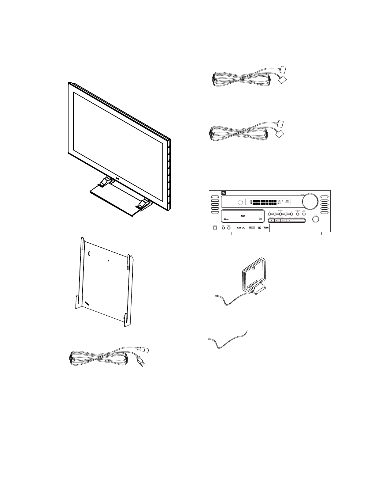
What’s Included
AUDIO / VIDEO RECEIVER / VIDEO PROCESSOR / OPTICAL DISC CHANGER
RL
SRSL
SBL
SBR
DIGITAL EX
LOGIC 7
96/24
NEO:6
PRO LOGIC II
57CH. STEREO
DVD A MP3 6:9 4:3
SVCD P-SCAN
P
CM 192K 96K
RANDOM PROGRAM
RPERAT DISC ALL
DSP SURR.
Abwicklung
M1:5
CVPD50 Carton Contents:
One CVPD50 50-Inch Plasma Display Screen (shown with
credenza stand)
One JBL Digital Link cable to connect the CVPD50 screen
to the CVR700 (3 meters; 5- and 10-meter lengths available
separately), packed with CVPD50
One VGA to DVI cable for analog PCs (3 meters), packed with
CVPD50
CVR700 Carton Contents:
One CVR700 audio/video receiver/video processor/optical disc
changer with owner’s guide, quick-start guide and warranty
cards.
One wall-mount bracket for the CVPD50 screen
One AM loop antenna
One FM antenna
One power cord for the CVPD50 screen (packed with CVPD50)
10
Page 11
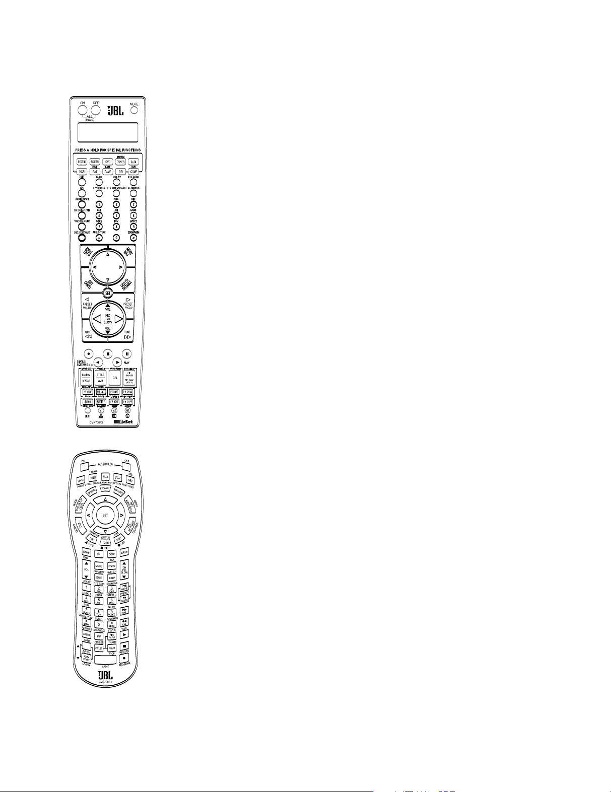
What’s Included (continued)
One CVR700R2 remote control
One CVR700R1 remote control
11
Page 12

383940
41
4647484950515253545556
57
38
39
40
41
2
5
24
2
3
22
2
1
20
3
7
36
3
5
34
33
3
2
3
1
3
7
36
3
5
34
3
3
3
2
48
49
50
51
4
7
46
4
5
44
4
3
4
2
6
8 9 10111
2
323334353
6
ReWritable
DISC FORMATS SUPPORTED BY THIS PLAYER
12
The unit can play the following types of
discs:
Audio CD Compatibility:
• 8cm (3") or 12cm (5") discs
• Linear PCM digital audio
Audio CDs are divided into tracks
•
DVD CD
8cm (3") disc 8cm (3") disc
12cm (5") disc 12cm (5") disc
The CVR700 will also play most DVD-
ideo, DVD-R, DVD-RW, DVD+R or
V
DVD+RW blank discs, but we cannot guarantee complete playback compatibility of
DVD-recordable discs due to the wide
variation in recorders and blank discs.
CD-R/RW Compatibility:
12cm (5") discs
•
• Linear PCM, MP3 (32kbps – 320kbps)
or Windows Media
®
WMA (16kbps –
192kbps) digital audio
May contain JPEG still images (up to
•
5 megapixels, file size up to 5mb)
• Linear PCM discs are generally divided
into tracks like an audio CD. MP3,
WMA and JPEG discs (or discs that
contain more than one of these formats) are divided into files, which may
be organized into folders, depending on
how the disc was created.
VCD Compatibility:
CD-RW CD-R VCD
12cm (5") 8cm (3") 8cm (3")
12cm (5") 12cm (5")
NOTE: Playback of CD-R or CD-RW discs
created on a computer requires proper
formatting and finalization of the disc for
audio playback. Some computers and/or
software programs may not be capable of
creating compatible discs.
DVD-Video Disc Compatibility:
• 8cm (3") or 12cm (5") discs
• Single-sided or double-sided discs
• Single-layer or dual-layer discs
• Dolby Digital, DTS, MPEG or Linear
PCM digital audio tracks
• MPEG-2 digital video
• Discs are generally divided into one or
more titles, which may be further subdivided into chapters.
DVD-Audio Disc Compatibility:
• 8cm (3") or 12cm (5") discs
• Single-sided discs
• Single-layer or dual-layer discs
Linear or packed PCM digital audio
•
• Some discs may contain MPEG-2 video,
and Dolby Digital, DTS or MPEG digital
audio
• Discs are generally divided into one or
more groups, which may be further
subdivided into tracks.
• 12cm (5") discs
• Linear PCM, MP1 (MPEG-1, Layer 1),
MP3 (MPEG-1, Layer 3) digital audio
• MPEG-1 digital video
• May contain JPEG still images (Video
CD Version 2.0)
• Some discs may contain menus and
chapters, while other discs simply contain tracks. Version 2.0 discs may offer
interactive playback control (PBC).
However, it will NOT play the following:
• DVD discs with a Region Code other
than that indicated on the rear panel
• DVD-ROM data discs
• DVD-RAM discs
CD-I discs
•
• CD-G discs
• SVCD discs
®
• Kodak
Photo CD discs (Kodak Picture
CD discs, which are available to consumers, contain files in the JPEG format which may be viewed using the
CVR700.)
NOTE: Due to differences in the format
ting of certain discs, it is possible that
some discs may include features that
are not compatible with the CVR700.
Similarly, although the CVR700 is capable
of a wide range of features, not all discs
include every capability of the DVD sys
tem. For example, although the CVR700 is
compatible with multi-angle discs, that
ture or soundtrack option is available,
please check the options noted on the
disc jacket.
• Playback capability for CD- or DVDrecordable discs may vary due to variations in the quality of the disc and the
recorder used to create the disc.
• The CVR700 is compatible with most
discs recorded with files encoded using
MP3 or Windows Media 9, as well as
JPEG still images. However
variations in the encoder or codec used
and the bit rate of the encoding may
affect the CVR700’s ability to play back
a specific disc. As a result, we cannot
guarantee complete compatibility with
all encoders and versions of the codecs.
For best results, we recommend that
MP3 files be encoded at bit rates ranging between 32kbps and 320kbps.
WMA files should be encoded at bit
rates between 16kbps and 192kbps.
JPEG files should contain no more than
5 megapixels, and the file size should
be no larger than 5Mb.
Note on DVD-Audio Discs: Due to the
newness of this format and some authoring issues, it is possible that some DVDAudio discs will not play, or that all features and menus may not be available.
Note that in many cases, in order to
access the disc menu, instead of pressing
the
Menu Button j , it is neces-
sary to press the
Title Button y or the
Audio Button U. In addition, many
DVD-Audio discs provide two menus: a
DVD-Audio menu and a DVD-V
intended for use on older players that do
not support the DVD-Audio format. If you
wish to view the DVD-Video menu and
access surround modes and other fea
tures only available through that menu
(such as Dolby Digital 5.1 or PCM audio
tracks), you will need to temporarily dis
able the CVR700’s DVD-Audio capability
using the DVD Setup menu (see Fig. 31).
-
, note that
ideo menu
-
-
feature is only possible when the disc is
specially encoded for multiple-angle play.
In addition, the CVR700 is capable of
playing back both Dolby Digital and DTS
soundtracks, but the number and types of
tracks available will vary from disc to
o make certain that a specific fea
disc. T
-
Page 13

TERMINOLOGY
383940
41
4647484950515253545556
57
38
39
40
4
1
2
5
24
2
3
22
21
20
37
3
6
35
3
4
3
3
32
3
1
37
36
3
5
34
33
3
2
48
49
50
5
1
47
46
4
5
44
43
4
2
6
8 9 10111
2
50515253545556
57
38
39
40
41
31
3
7
36
3
5
34
33
3
2
48
49
50
51
4
7
46
4
5
44
43
4
2
6
16171
8
Home theater equipment has changed a
great deal since the first VCR was introduced about 30 years ago. Some of the
terms used to describe and configure
your CVPD50 PDP plasma display monitor
and the internal DVD/CD changer in your
CVR700 may be unfamiliar
these terms are described in this section.
Since they share some of the characteristics and technology of CD players, many
of the terms and operational concepts
used in a DVD player are similar to what
you may be familiar with from CD players
and changers, or older video disc formats
such as Laser Disc. However, if this is
your first DVD product, some of the terms
used to describe the features of a DVD
player may be unfamiliar. The following
explanations should solve some of the
mysteries of DVD, and help you to enjoy
all the power and flexibility of the DVD
format and the CVR700.
With the arrival of DVD, disc data capacity has increased dramatically. On a DVD
Video disc, most of this capacity is taken
up by MPEG 2 video and the multichannel
movie soundtrack in Dolby Digital and/or
DTS. This information is compressed. But
with DVD Audio, most of this capacity is
available for music only, without any
compression. This allows us to put the
audio information on the disc in the same
quality as the original mastering in the
studio, in PCM up to 24-bit/192kHz.
DVD-Audio’s 24-bit system provides substantially improved resolution of fine
detail, because it describes a specific
point in the musical information using
a 24-digit-long string of ones and zeros
with 16,777,216 possible combinations,
while CD’s primitive 16-bit system offers
only 65,536 options. The 192kHz frequency
allows us to have fast changes in music
made audible, which results in more
dynamism, and also allows us to obtain a
higher bandwidth, up to 96kHz. Although
that is far beyond the human audible
spectrum, it still improves the musical
realism.
. Some of
Aspect Ratio: This is a description of
the width of a video image in relation to
its height. A conventional video screen is
four units wide for every three units of
height, making it almost square. Newer
wide-aspect-ratio video displays are 16
units wide for every nine units of height,
making them more like the screen in a
movie theater. The program material on a
DVD may be recorded in either format.
video signal is of higher resolution
than 480i or DVI, you may need to
repeatedly press the
z on your remote con-
Button
Letterbox
trol to select either the “2.35 LTRBOX
TO 16:9” or “2.35 LB TO 16:9
CROPPED” mode, choosing the mode
that provides the picture most pleasing to you. Note that the cropped
mode may leave out portions of the
frame in order to fit the image to the
NOTES:
n Due to the advent of HD (high-defini-
tion) programming and the new 16:9
(also called 1.85 or widescreen) aspect
ratio, many newer sources now offer
their own scaling (resizing of the picture to fit a frame) options which are
accessed through their remote or
through their on-screen menu. T
o take
advantage of CVR700’s robust scaling
capabilities, it is best to allow the
CVR700 to handle all rescaling duties.
This means that all high-definition
external sources connected to CVR700
should be configured to supply a 16:9
picture to CVR700 if at all possible
and all non-HD legacy sources should
supply their native 4:3 (otherwise
called 1.33 or FULL SCREEN) aspect
ratio (with older devices, there are
usually no adjustments or options for
picture size, anyway). Regarding HD
sources, some experimentation may
be necessary, as not all offer a basic
16:9 aspect ratio option without other
parameter settings. The correct mode
may be called 16:9 FULL SCREEN in
some brand products; in other brand
products, you may need to select the
16:9 aspect ratio separately from
selecting FULL SCREEN scaling. Some
experimentation with the settings on
your source device may be necessary
to find the most pleasing appearance.
n There are two film formats commonly
used in movie theaters today that are
close to the 16:9 aspect ratio of your
CVPD50 screen – 1.85:1 and 2.35:1.
The aspect ratio of your screen is
1.78:1, which is very close to the
1.85:1 film ratio that is found in many
movies recorded on DVDs or broadcast
on television, and these programs will
fill your screen. However, some
movies are filmed in the wider 2.35:1
ratio. Check the jacket of your DVD to
find its aspect ratio. When playing
such a DVD on your JBL Cinema Vision
system, if you have turned off the DVD
Auto Resize feature, or if your analog
screen, and you may prefer the scaled
mode, even though black bars will
appear on the top and bottom of your
screen.
If you have turned off the DVD Auto
Resize feature, you may also choose how
to view 4:3 ratio images. Y
ou may view
the image as is, in which case black bars
will appear on the left and right sides of
the screen. You may set the system to
stretch the image to fill the screen, using
either linear (the stretch is even across
the entire image) or non-linear (the
stretch is more pronounced towards the
edges of the image, leaving the center
nearly unmodified) scaling. When the
4:3 ratio image consists of a letterboxed
movie, you may simply zoom in to remove
the black bars at the top and bottom of
the screen.
Chapter: DVD programs are divided into
chapters and titles. Chapters are the subsections programmed into a single title
on a disc. Chapters may be compared to
the individual tracks on an audio CD.
Press the
Menu Button
j
to see
a listing of the chapters on a disc. On
DVD-Audio discs, a Chapter is referred
rack.
to as a T
Component V
This form of video
ideo:
signal eliminates many of the artifacts of
traditional composite video signals by
splitting the signal into a separate lumi
nance channel (the Y signal channel) and
two color-difference signals (the Pr and
Pb signal channels). With a component
video connection, you will see greater
picture resolution and eliminate many
picture imperfections such as the moiré
patterns often seen on check-patterned
cloth. However, in order to benefit from
component video you must have a video
display with Y/Pr/Pb component video
inputs. Do not connect the component
video outputs of the CVR700 to the stan
dard composite or S-video inputs of a
TV or recorder
.
NOTE: The CVR700 is optimized to be
used with the CVPD50 High-Definition
-
-
13
Page 14

4
0
41
484950515253545556
57
38
39
4
0
41
3
7
36
3
5
34
33
3
2
3
1
37
3
6
3
5
34
33
3
2
48
49
5
0
51
47
4
6
4
5
44
43
4
2
6
14
Plasma Display. Composite, S-video and
component video monitor outputs on the
CVR700 are provided as a means of connecting an auxiliary display only. Onscreen status messages, and all digital
video post-processing – including scaling,
de-interlacing, and upconversion features
of the CVR700 – are only available when
used with the CVPD50.
When using the CVR700 with the CVPD50
display, there is no need to use the
CVR700’s component video outputs. All
video signals, including those from the
internal DVD/changer as well as those
originating with external source devices,
are upconverted to the digital format utilized by the single proprietary interface
cable between the CVR700 and the
CVPD50.
High-Definition Television (HDTV):
HDTV is a form of digital television that
advances picture quality by leaps and
bounds over conventional analog television. HDTV signals are broadcast in a digital format that compresses the signal,
allowing far more information to be sent.
Broadcasters take advantage of the additional bandwidth by offering high-resolution images containing millions more pixels than an analog picture, the end result
being an image so sharp it looks more
like a photograph than television.
The resolution of a digital video signal
can vary, depending on the number of pixels used, and whether the image frames
are interlaced or progressive. Conventional
television uses interlaced frames, in
which first the odd horizontal pixels are
scanned, then all of the even pixels are
scanned to display one frame. Progressive
scanning, as described below
, displays
all of the horizontal lines of pixels in one
pass. These are the common digital video
formats:
• 480i – The picture is 704 x 480 pixels,
sent at 60 interlaced frames per sec
ond (30 complete frames per second).
• 480p – The picture is 704 x 480 pixels,
sent at 60 complete frames per second.
• 720p – The picture is 1280 x 720 pix-
els, sent at 60 complete frames per
second.
• 1080i – The picture is 1920 x 1080
pixels, sent at 60 interlaced frames
per second (30 complete frames per
second).
• 1080p – The picture is 1920 x 1080
pixels, sent at 60 complete frames per
second.
The “p” and “i” designations stand for
“progressive” and “interlaced.”
The 480p and 480i (when digital) formats
are called the SD (standard-definition)
formats, and 480i is the digital equivalent
of a normal analog TV picture. When analog TV shows are upconverted and broadcast on digital TV stations, they are
broadcast in 480p or 480i.
The 720p, 1080i and 1080p formats are
HD (high-definition) formats. When you
hear about “HDTV,” this is what is being
discussed – a digital signal in the 720p,
1080i or 1080p format. If your HD source
allows you to choose a picture resolution,
set it to 720p, which works best with the
CVR700 and CVPD50.
Strictly speaking, the 480p format is considered ED (enhanced definition). However,
the JBL Cinema Vision system processes
480p signals as high-definition, and when
referring to high-definition signals, we
will be talking about 480p or better
images.
JPEG Files: JPEG stands for the Joint
Photographic Experts Group, which developed a standard for compressing still
images, such as photographs. JPEG files
may be created on a personal computer
by importing images from a digital camera, or scanning printed photographs.
These files may be burned onto a compact disc. The CVR700 is among the DVD
players that are capable of recognizing
JPEG files and enabling you to view them
on your video screen.
MP3 Files: MP3 is an audio compression
format that was developed by the Motion
Picture Experts Group as an adjunct to the
MPEG-1 video compression format. A
number of encoding software programs
are available for transferring CDs and
other audio programs into the MP3 for
mat. The main benefit of MP3 is that it
reduces the size of audio files consider
ably, depending on the amount of compression selected during the encoding
process, enabling you to store many more
songs on one compact disc than in the
standard audio CD format. The CVR700 is
capable of playing MP3 files and displaying the filenames on screen.
Multiple Angle: DVDs have the capability to show up to four different views of
the same scene in a program. When a
disc is encoded with multiple-angle information, pressing the
E
will enable you to switch
Angle Button
between these different views. Note
that, at present, few discs take advantage of this capability and, when they do,
the multiple-angle technology may only
be present for short periods of time within the disc. Producers will usually insert
some sort of icon or graphic in the picture
to alert you to the availability of multipleangle scenes.
Progressive scan: If you are using the
CVR700 with the CVPD50 display, and
with no external DVD players, you may
skip this section, as the internal DVD
player outputs a digital video signal that
is passed directly to the CVPD50 using
the proprietary interface cable. The
CVR700 offers progressive scan video
outputs for use with compatible high-resolution televisions and projectors. Before
DVD, no consumer medium could store,
transmit or display video with full resolution. To conserve bandwidth, analog compression (interlacing) is employed: first
the odd-numbered lines of a frame are
displayed, followed by the even-numbered lines. The result is that only half of
the video image is drawn at one time; the
viewer’s brain must reassemble the complete image. This is acceptable, if the
monitor is not too large and if there is not
too much motion in the image. Large displays and fast-moving images reveal the
limitations of this system. Thanks to
s immense data capacity, images are
DVD’
now stored intact (progressively), so that
all the lines in each frame (odd and even)
are shown at the same time. But because
most TVs cannot handle a progressive
signal, all current DVD players generate
an interlaced output for compatibility
CVR700 is among the select few DVD
players with true progressive scan video
output for use with compatible TVs and
CRT projectors and with all plasma, LCD
-
and DLP display devices via the compo
nent video output. The result is 40%
-
greater light output than a conventional
TV and a stunningly detailed high-definition image, along with an almost com
plete absence of visible scanlines and
motion artifacts. The CVR700’s sophisticated pixel-by-pixel processing is a major
advancement over the previous generation’s line-by-line processing, bringing out
even greater detail in your favorite video
presentations. Of course, traditional
Y/Pr/Pb component video, S-video and
. The
-
-
Page 15

composite video outputs are included for
40
41
484950515253545556
57
38
39
40
41
37
36
35
34
33
32
31
37
36
35
34
33
32
48
49
50
51
47
46
45
44
43
42
6
56
57
48
49
50
51
6
56
57
48
49
50
51
4
3
6
56
57
48
49
50
5
1
7
5
2
6
1
2
383940
41
4647484950515253545556
57
38
39
40
41
25
24
23
2
2
21
2
0
37
36
3
5
34
3
3
3
2
31
37
3
6
35
3
4
33
32
48
49
50
51
47
4
6
45
4
4
43
42
6
8 9 10 11 12
202122232
4
56
57
48
49
50
51
7
5
3
2
6
1
8
2
4
56
57
4
8
49
50
51
7
5
2
6
383940
41
4647484950515253545556
57
38
39
40
41
25
24
23
22
2
1
20
3
7
3
6
3
5
3
4
33
3
2
3
1
37
3
6
35
34
3
3
3
2
48
49
50
51
47
4
6
45
44
4
3
4
2
6
8 9 10 11 12
141516171
8
use with conventional televisions and
projectors.
Reading: This is a message that you will
see when you first press the
A
e
. It refers to the fact that the
Play
Button
player must first examine the contents of
the disc to see whether it is a CD or DVD,
and then extract the information about
the type of material on the disc, such as
languages, aspect ratios, subtitles, number of titles and more. The slight delay
while the contents of the disc are read
is normal.
Resume: The operation of the Stop
Button
C
M
on the CVR700 works
differently from what you are used to on
CD players. On a traditional CD player,
when you press the Stop button, the unit
does just that: it stops playback. On a CD
player,
when you press the Start button
again, the disc starts from the beginning.
With the CVR700, however, you have two
options when playing DVD discs. Pressing
Stop ButtonCM
the
once will
stop the playback, but it actually puts the
unit in the Resume mode. This means
that when you press the
A
e
the next time, the disc will
Play Button
resume or continue from the point on the
disc where the
Stop ButtonCM
was pressed. This is helpful if you are
watching a movie and must interrupt
your viewing session but wish to pick up
where you left off. Pressing the
Button
C
M
twice will stop the
Stop
machine in a traditional manner and,
when the disc is played again, it will
start from the beginning.
include only one title, but some may have
more than one, to give you a “Double
Feature” presentation or to include other
special features. Press the
O
to see a listing of the titles on a disc.
Title Button
When a disc has only one title, pressing
itle Button
the
T
O
may show a list of
the chapters.
On DVD-Audio discs, a Title is referred
•
to as a Group. Many DVD-Audio discs
require you to press the
O
to access the disc menu.
Title Button
WMA Files: WMA (Windows Media
Audio) is another audio compression
format that was developed by the
Microsoft
®
Corporation for use with its
Windows Media Player. WMA files can
be even smaller in size than MP3 files,
while maintaining similar quality. The
CVR700 is among the DVD players capable of playing discs containing WMA
files. Note that Windows Media Player
uses other file formats; however, the
CVR700 is only capable of playing files
that end in the “.wma” extension.
Note that the Resume function will be
canceled if you shut the unit off (place
it in Standby mode), change to another
disc or select a different source. Also,
there may be a brief 1- to 2-second delay
between the second press of the
Button
acknowledging the mode change in the
Upper Display Line H.
The resume function is not available for
CDs, VCDs or JPEG files. For DVDs only,
the resume function will be retained even
after the CVR700 has been placed in
Standby mode by pressing the
Off Button
Title: For a DVD, a title is defined as an
entire movie or program. There may be as
many chapters within a title as the pro
ducers decide to include. Most discs
Stop
C
M
and the CVR700
10 .
Power
-
15
Page 16
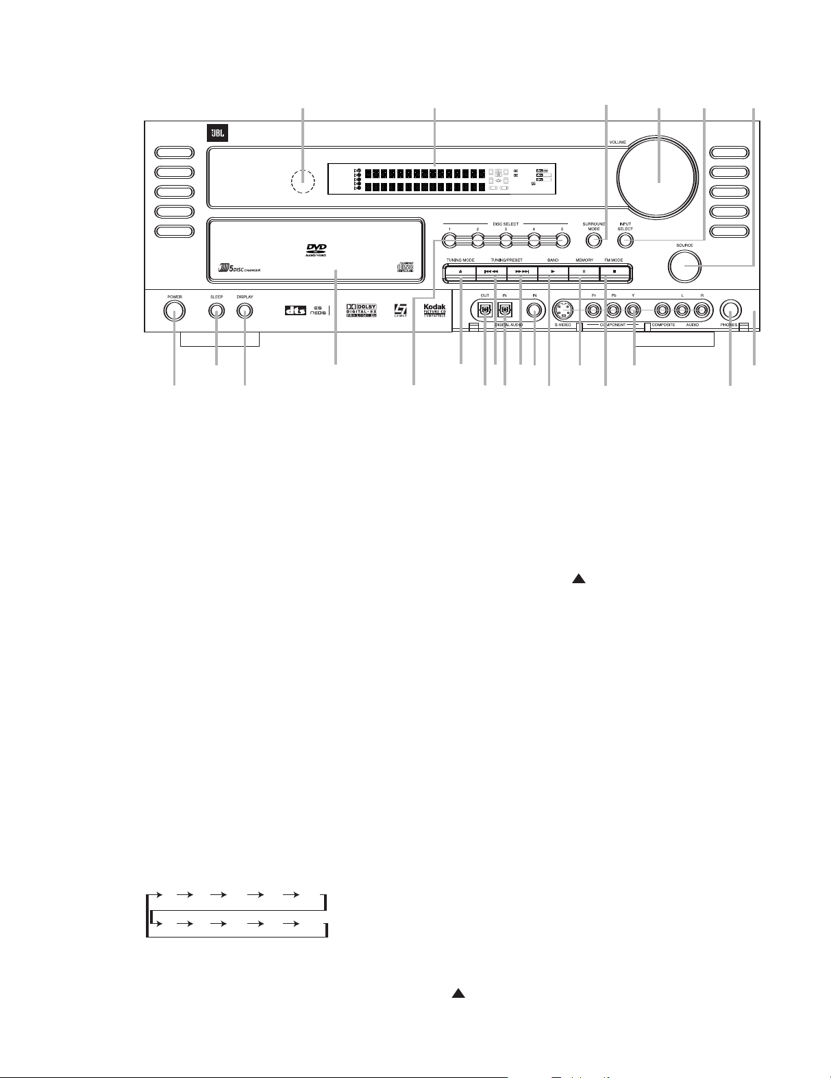
CVR700 FRONT-PANEL CONTROLS
5
%
1
7
6
9
!
#
3
2
Ô
Ó
4
8 8
)
$
@
^
&
(
*
A
UDIO / VIDEO RECEIVER / VIDEO PROCESSOR / OPTICAL DISC CHANGER
RL
S
RSL
SBL
SBR
DIGITAL EX
L
OGIC 7
96/24
NEO:6
PRO LOGIC II
57CH. STEREO
DVD A MP3 6:9 4:3
S
VCD P-SCAN
PCM 192K 96K
R
ANDOM PROGRAM
RPERAT DISC ALL
DSP SURR.
G
AME/CAM
3637383940
41
44454647484950515253545556
57
38
39
40
41
1
2
0
9
2
5
26
2
7
28
2
9
3
0
24
2
3
2
2
21
20
31
37
3
6
35
3
4
3
3
32
3
1
3
7
36
3
5
34
33
32
48
49
50
51
4
7
46
4
5
44
43
42
1 2 3 4 5
6
7
8 9 10 11 12
13 14 15 16 17 18
383940
41
4647484950515253545556
57
38
39
40
41
25
24
23
22
21
20
37
36
35
34
33
32
31
37
36
35
34
33
32
48
49
50
51
47
46
45
44
43
42
6
90
min80min70min60min50min
OFF
40
min30min20min10min
0
Main Power On/Off
1
Sleep Button
2
Display Dimmer
3
Disc Drawer
4
Disc Selector
5
Tuning Mode/Eject Button
6
Front-Panel Optical Digital Audio
Output
7
Tuning/Preset/Skip/Search Button
8
Front-Panel Optical Digital Audio Input
9
Front-Panel Coaxial Digital Audio
Input
!
Tuner Band Selector/Play Button
B
Memory/Pause Button
#
FM Mode/Stop Button
$
Front-Panel Audio/Video Inputs
%
Headphone Jack
^
Front-Panel Door
&
Source Selector
*
Surround Mode Selector
(
Input Select Button
Ó
Volume Control
Ô
Information Display
Remote Sensor Window
16
1 Main Power On/Off: Press this but-
ton to apply power to the CVR700. The
LED indicator in the center of the button
will turn orange. Press it again to place
the CVR700 in Standby mode, and the
LED indicator will turn red.
If the CVPD50 is in use, pressing this button will also turn the CVPD50 on or off,
if it is plugged into AC power and its
master power switch has been turned
on. If the LED on the CVPD50’s front panel
is flashing, then check that its master
power switch is on (the “1” position).
2 Sleep Button: Press this button to
place the unit in the Sleep mode. After
the time shown in the display, the
CVR700 will automatically go into the
Standby mode. Each press of the button
changes the time until turn-off in the following order:
When the Sleep timer is in use, the frontpanel displays and other indicators will
dim to half-brightness.
3 Display Dimmer: Press this button to
reduce the brightness of the
Display
Ô by 50%, or to turn the dis-
Information
play off completely, in the following order:
FULL BRIGHTNESS -> HALF BRIGHTNESS
-> OFF -> FULL BRIGHTNESS.
4 Disc Drawer: This drawer is used to
access the five-disc magazine changer.
While a disc is playing, you may load a
disc into or remove a disc from another
location in the changer. If you select the
current disc, it will first stop playing. Seat
all discs carefully within the recess in the
drawer. Do not press down on the drawer
when it is open, to avoid damage to the
. It is also best to open and close
player
the drawer by pressing the
6 rather than by pushing the drawer
itself.
Eject Button
5 Disc Selector: Press one of these
buttons when prompted by a message on
Lower Display Line E and on the
the
CVPD50 screen for a disc number after
pressing the
Eject Button 6. If you
have selected the internal disc changer
as the source device using the
Selector
Input Selector
control, and then pressed the
Button
& or by pressing the DVD
d on either remote
Play
! or Disc Direct Button a
Source
, the CVR700 will prompt you to enter
a disc number by pressing one of these
buttons.
6 Tuning Mode/Eject Button: This
button’s function varies, depending on
whether you have selected the tuner or
the disc changer as the current input
source. When the tuner is the source,
press this button to select the function
uning/Preset Buttons
of the
T
press will alternate between the tuning
function and the preset selections func
tion, with the current choice displayed
Lower Display Line E.
on the
When the tuning function has been
selected, each press of one of the
Tuning/Preset Buttons 8 will tune the
next higher or lower frequency
, regardless
of whether an acceptable signal is avail
uning Button
able. Press and hold the
T
8 to scan up or down through the frequencies until a station with acceptable
signal quality is located. Tap the
8 again to end the scan.
Button
When the preset selection function is in
force, each press of one of the
Preset Buttons
8 will tune the next
Tuning/
higher or lower preset station that was
previously stored in the CVR700’s memory.
8. Each
-
-
Tuning
Page 17

See page 64 for information on storing
383940
41
4647484950515253545556
57
38
39
40
41
2
5
24
2
3
22
2
1
2
0
3
7
36
3
5
34
3
3
32
31
37
36
3
5
3
4
33
3
2
48
49
50
51
47
46
4
5
4
4
43
4
2
6
8 9 10 11 12
141516171
8
preset stations.
When the disc changer is the source,
press this button to open or close the
Disc Drawer 4. The Lower Display
Line
number. Press the
responding to the number of the drawer
you wish to access.
7 Front-Panel Optical Digital Audio
Output:
of an audio or video product to this jack.
8 T
Buttons:
varies depending on whether you have
selected the tuner or the disc changer as
the current input source, and in what con
text you press it.
When the tuner is the source, press the
left button to tune lower-frequency stations and the right button to tune higherfrequency stations. Each tap of the buttons will increase or decrease the frequency by one increment. Press and hold
the button, and the tuner will scan for a
station with acceptable signal strength.
When the next higher or lower frequency
station with a strong-enough signal is
tuned, the frequency scan will pause.
Press the button again to stop scanning.
When the tuner is the source and you
have pressed the Tuning Mode Button
6 so that PRESET appears in the
Lower Display Line E, pressing these
buttons enables you to scroll through the
list of stations that have been previously
stored in the CVR700’
See page 64 for more information on
using the tuner
When the disc changer is the source,
press and release these buttons to move
(skip) either backward (left button) or for
ward (right button) through the tracks on
a DVD-Audio, CD or VCD disc or the
chapters on a DVD-Video disc. Press and
hold either button for at least 1 second
and then release to search either backward (left button) or forward (right button) the current track or chapter at 2x
speed. Press and hold again and release
to increase the scan speed to 4x. Repeat
this procedure while in scan mode to
cycle through these scan speeds: 2x, 4x,
16x, 100x, 2x and so forth. Press and
release the button while scanning to skip
tracks or chapters. To stop searching, you
must press the
Pause Button @, the Stop Button #
or the other Search Button 8.
E will prompt you to press a disc
Disc Selector 5 cor-
Connect the optical digital input
uning/Preset/Skip/Search
The function of these buttons
s memory
.
.
Play Button !, the
9 Front-Panel Optical Digital Audio
Input:
Connect the optical digital output
of an audio or video product to this jack.
) Front-Panel Coaxial Digital Audio
Input:
Connect the coaxial digital output
of an audio or video product to this jack.
! Tuner Band Selector/Play Button:
The function of this button varies depending on whether you have selected the
tuner or the disc changer as the source.
When the tuner is the source, pressing
this button will switch between the AM
and FM frequency bands. (See page 64
for more information on the tuner.)
When the disc changer is the source,
pressing this button will prompt you to
enter the number of the disc you wish
to play (corresponding to the drawer in
which the disc is loaded). You may select
a disc either by pressing one of the
Selectors
by pressing the
5 numbered 1 through 5, or
Numeric Keys l
numbered 1 through 5 on either remote
control. If you don’t select a disc number
within 5 seconds, the CVR700 will play
the last disc that was selected. If the disc
is an MP3 or WMA disc, each press of
this button will expand the current folder
until a file is located, and the final press
will begin play of that file. If no disc is
found, the
STOP MODE, DISC 1
message will appear and you will need to
open the drawer to insert a disc.
@ Memory/Pause Button: The func-
tion of this button varies depending on
whether you have selected the tuner or
the disc changer as the input source.
When the tuner is the source, press this
button to store the currently tuned station
as a preset. Two flashing underlines will
Upper Display Line H.
Tuning Mode Button 6
-
appear in the
Press the
until PRESET appears in the Lower
Display Line
of the
press either of the
E to indicate the function
Tuning/Preset Buttons 8, then
Preset Buttons 8
until the desired preset location appears
in place of the flashing underlines. Press
Memory Button @ again to store
the
the station in the preset location displayed.
When the disc changer is the source,
pressing this button during playback
freezes a picture (for DVD and VCD discs)
and pauses the playback signal. Pressing
Pause Button @ twice places the
the
DVD changer in the Step Forward mode,
in which each subsequent press of the
Pause Button @ advances the picture
one step or frame. Press the
Play or
Disc
Stop Button !# to exit the Step
Forward mode.
# FM Mode/Stop Button: The func-
tion of this button varies depending on
whether you have selected the tuner or
the disc changer as the input source.
When the tuner is the source, press this
button to switch between Stereo and
Mono modes for FM radio reception.
When weak reception is encountered,
select the Mono tuning mode. Press
again to switch back to Stereo mode.
See page 64 for more information.
When the disc changer is the source,
press this button once to stop playback
of the current disc and enter Resume
mode. In Resume mode, the CVR700 will
“remember” the point on the disc where
play was stopped, and the next time the
disc is played, it will commence playback
from this point, unless the unit was
turned off, another disc was selected or
another source was selected. To fully
stop the disc, press this button twice.
There may be a 1- or 2-second delay
before Stop mode takes effect. Resume
mode is not available for CDs, VCDs, MP3
discs or WMA discs. If one of those disc
types is playing, a single press of this
button will place the disc in Stop mode,
as indicated by the solid square and the
STOP appearing in the Upper
word
Display Line
$ Front-Panel Audio/V
H.
ideo Inputs:
The front-panel inputs give you the flexibility to temporarily connect a device to
the CVR700. This capability is useful for
such applications as viewing home
movies directly from the camcorder
, or
playing a video game. For video devices,
connect one of the composite video, Svideo or component video outputs of the
device to the corresponding front-panel
input, and connect the left and right
audio outputs to the analog audio inputs.
Do not make more than one type of video
connection. In addition to the analog
audio connection, you may also connect
an optical or coaxial digital audio output
from the device to the CVR700. You will
then need to press the
( to select the desired audio
Button
Input Select
input (analog, optical or coaxial), and
specify the correct video input using the
audio on-screen menu system. Press the
System Selector f, and then the
OSD Button n to enter the menu sys
tem. Select the
and make sure the
SOURCES submenu,
GAME/CAMERA
source is selected (or select the
-
17
Page 18

SOURCE line to adjust it). Scroll down
to the
VIDEO INPUT line and
select it to configure the CVR700 to use
the video input you connected your
device to.
% Headphones Jack: This jack may
be used to listen to the CVR700's output
through a pair of headphones. Be certain
that the headphones have a standard
1/4" stereo phone plug, or that you use
an adapter, as needed, to convert the
plug on your headphones to the 1/4" jack
used on the CVR700. When the head
phone jack is in use, the main room
speakers will automatically be turned off
and the unit will output a standard stereo
signal. For more information on headphone listening, see page 60.
^ Front-Panel Door: The door may
be closed to hide the front-panel jacks
when they are not in use for a smoother
appearance. To open the door, gently
push on the bottom of the door in the
center to swing it down towards you, or
gently pull on the upper right corner. Push
upward on it to close.
& Source Selector: Rotate this knob
to scroll through the available input
sources. Turn the knob slowly and gently,
and you will feel a soft click as each
source is engaged. You may also hear a
click as the CVR700’s electrical circuits
engage the source. This is normal, and
assures you that you have correctly
selected the source. The name of the
source will be displayed in the
Display Line
H, and in a Status Banner
Upper
on screen, together with the source’s
audio input (for external sources) and
video format.
* Surround Mode Selector: Press
this button repeatedly to scroll through
the available surround modes. The modes
available will depend on the number of
speakers in the system and whether the
input is analog or digital. See page 60 for
more information on surround modes.
NOTE: 6.1 and 7.1 digital modes are
available only when the appropriate digital bitstream is present.
( Input Select Button: After you have
selected the desired input source, press
this button repeatedly to scroll through
the analog, optical digital and coaxial
digital audio inputs available for that
source.
Ó Volume Control: Turn this knob
clockwise to increase the volume, counterclockwise to decrease the volume. If
the CVR700 is muted, adjusting the volume control will automatically release
the unit from the silenced condition.
Ô Information Display: This display
delivers messages and status information
to help you operate the CVR700. See
page 19 for a complete explanation of
the display.
Remote Sensor Window: The sensor behind this window receives infrared
signals from the remote control that are
intended to control the non-video functions of the CVR700 only. Aim the remote
at this area and do not block or cover
it unless an external remote sensor is
installed. Note that unless the CVR700
is not being used with the CVPD50, it is
best to aim the remote at the LED light
on the front of the CVPD50 plasma display, as the IR receiver located there can
accept remote control signals intended
for both the plasma display and the
CVR700.
18
Page 19
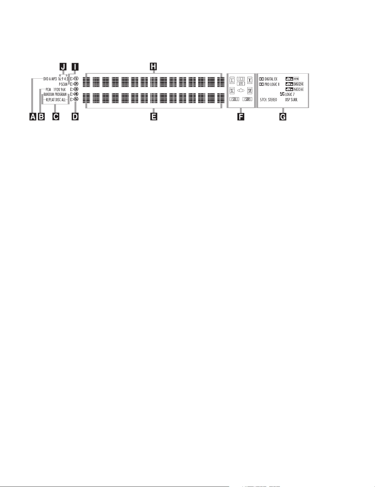
CVR700 FRONT-PANEL INFORMATION DISPLAY
A Disc-Type Indicators
B PCM Bitstream Indicators
C Programmed Play Indicators
D Disc Indicators
A Disc-Type Indicators: The DVD,
DVD-Audio, CD, VCD or MP3 indicator
will light to show the type of disc currently being played. WMA and JPEG
discs will be identified in the
Lower Display Lines EH.
B PCM Bitstream Indicators: The
PCM indicator will light when a PCM
(pulse code modulation) bitstream is
detected. PCM bitstreams are used on
audio CDs, and may also be found on
other disc types either as the main audio
format or as the format used on certain
portions of the disc, such as a “making
of” featurettes on a DVD. The 96K or
192K indicators will light when a highresolution audio signal is detected. This
type of audio track may be found on
some DVD-Audio discs.
C Programmed Play Indicators: The
CVR700 is capable of playing discs in a
programmed order other than the order in
which the tracks are found on the disc.
racks may be played in random order
T
or you may program some or all of the
tracks on a CD to play in a playlist order.
In addition, you may program the CVR700
to repeat play of some of the tracks on a
disc, an entire disc, all discs, or a pro
grammed playlist. Some of the programmed modes may not be available
for certain disc formats. See page 75
for more information.
D Disc Indicators: The circled num
bers will light to indicate the positions of
loaded discs, and the indicator for the
current disc will flash.
Upper and
,
-
-
E Lower Display Line
F Speaker/Channel Input Indicators
G Surround Mode Indicators
H Upper Display Line
E Lower Display Line: Depending on
the unit’s status, a variety of messages
will appear here. In normal operation, the
current surround mode will appear on
this line.
F Speaker/Channel Input Indicators:
These indicators are multipurpose, indicating both the speaker type selected for
each channel and the incoming data signal
configuration. The left, center, right, right
surround and left surround speaker indicators are composed of two boxes, while the
subwoofer is a single box. The inner box
lights when a “small” speaker is selected,
and the outer boxes light when “large”
speakers are selected. When none of the
boxes are lit for the center, surround or
subwoofer channels, no speaker has been
assigned that position. (See page 48 for
more information on configuring speakers.)
The letters inside each box display the
active input channels. For standard analog
inputs, only the L and R will light, indicating a stereo input. For a digital source, the
indicators will light to display the channels
being received at the digital input. When
the letters flash, the digital input has been
interrupted. When a 6.1-channel bitstream
is detected, a horizontal line will appear
between the icons for the surround back
left and right channels to indicate that
these two channels are in mono mode.
(See page 61 for more information on the
Channel Indicators.)
G Surround Mode Indicators: One of
these indicators will light to show the
surround mode in use. Depending on the
specific combination of input sources and
surround mode selected, more than one
indicator may light. (See page 61 for
more information.)
I Progressive Scan Indicator
J Aspect Ratio Indicator
H Upper Display Line: Depending on
the unit’s status, a variety of messages
will appear here. In normal operation,
this line will show the current input
source and identify whether an analog
or digital input is in use. When the tuner
is selected as the input, this line will
identify the station as AM or FM and
show the frequency and preset number,
if any.
I Progressive Scan Indicator: This
indicator lights when the CVR700’s
progressive scan component video output
is activated.
J Aspect Ratio Indicators: The
aspect ratio of the incoming video signal
will light. These indicators are informational only and reflect the aspect ratio
information provided by the DVD disc
ou may need or wish to make
itself. Y
manual adjustments to display the
images so that they fill the screen, or if
you prefer to avoid any scaling or cropping of the images, you may wish to let
terbox the image. See pages 13 and 27
for more information on adjusting the
CVPD50 display to compensate for various aspect ratio issues.
-
19
Page 20
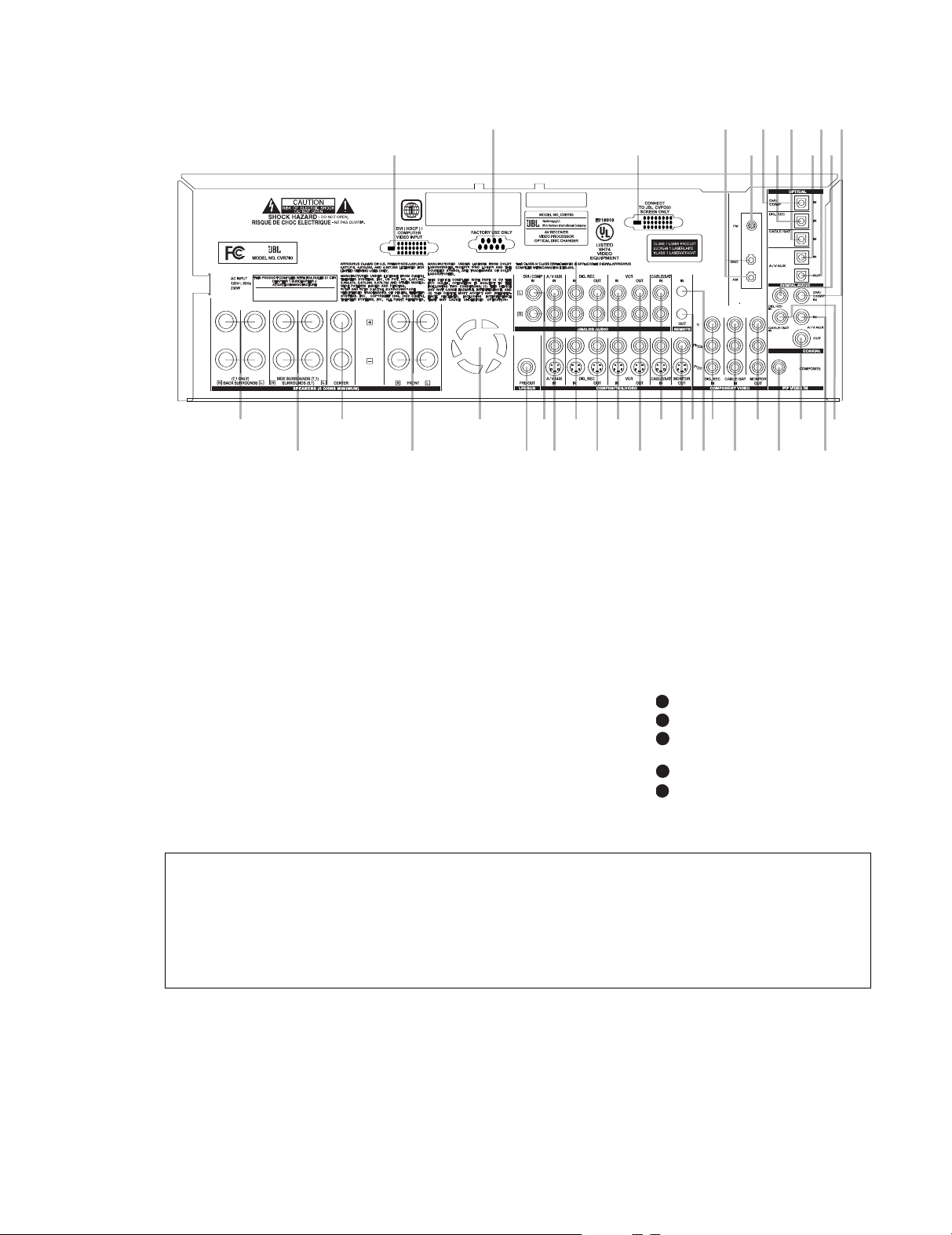
CVR700 REAR-PANEL CONNECTIONS
¡
™
£
¢
∞
§
¶
•
ª
‚
⁄¤‹
›
fi
fl
‡
°
·
a
b
c
d
e
f
g
h
i
j
k
U
V
W
X
Y
5253545556
57
39
40
41
37
36
35
49
50
51
47
46
45
5253545556
57
38
39
40
41
37
36
35
34
48
49
50
51
47
46
45
44
5253545556
57
38
39
40
41
37
36
35
34
33
48
49
50
51
47
46
45
44
43
5253545556
57
38
39
40
41
37
36
35
34
33
32
48
49
50
51
47
46
45
44
43
42
052
53
5
4
55
5
6
57
38
39
40
41
31
37
36
35
34
33
32
48
49
50
51
47
46
45
44
43
42
NOTE: To make it easier to follow the instructions that refer to this illustration, a larger copy may be downloaded from the Product
Support section for this product at www.jbl.com.
0 Back Surround Speaker Outputs
(7.1-channel only)
1 Side Surround (7.1-channel) or
Surround (5.1-channel) Speaker Outputs
2 Center Speaker Outputs
3 Front Speaker Outputs
4 Fan Slots
5 Subwoofer Output
6 DVI/Computer Analog Audio Inputs
7 Auxiliary Analog Audio/Video Inputs
8 Digital Recorder Analog Audio/Video
Inputs
9 Digital Recorder Analog Audio/Video
Outputs
A VCR Analog Audio/Video Inputs
B VCR Analog Audio/V
ideo Outputs
C Cable/Satellite Analog Audio/Video
Inputs
D Composite and S-Video Monitor
Outputs
E Remote IR Output
F Remote IR Input
G Digital Recorder Component Video
Inputs
H Cable/Satellite Component Video
Inputs
I Component Video Monitor Outputs
J Picture-in-Picture (PIP) Composite
Video Input
b Coaxial Digital Audio Output
c Auxiliary Coaxial Digital Audio Input
d Cable/Satellite Coaxial Digital Audio
Input
e DVI/Computer Coaxial Digital Audio
Input
f Digital Recorder Coaxial Digital Audio
Input
g Optical Digital Audio Output
h Auxiliary Optical Digital Audio Input
i Cable/Satellite Optical Digital Audio
Input
j Digital Recorder Optical Digital Audio
Input
k DVI/Computer Optical Digital Audio
Input
FM Antenna Jack
AM Antenna Terminals
Output to JBL Cinema V
ision CVPD50
Screen
Port for Factory Use Only
DVI (HDCP)/Computer Video Input
NOTE: To assist in making the correct connections for multichannel input, output and
speaker connections, all connection jacks and
terminals are color-coded in conformance
with the CEA standards as follows:
Front Left: White
Front Right: Red
Center:
Side Surround/Surround Left: Blue
Green
Side Surround/Surround Right: Gray
Back Surround Left:
Brown
Subwoofer: Purple
Digital Audio: Orange
Composite V
Component Video “Y”: Green
ideo:
Component Video “Pr”: Red
Component V
ideo “Pb”:
ellow
Y
Blue
Back Surround Right: Tan
¡ Back Surround Speaker Outputs:
These speaker terminals are normally
used to power the back surround left/
back surround right speakers in a 7.1-
20
channel system. In conformance with the
CEA color
-code specification, the brown
terminal is the positive (+) terminal that
should be connected to the red (+) terminal on the Back Surround Left speaker
with older color-coding, while the tan
terminal should be connected to the red
(+) terminal on the Back Surround Right
speaker with the older color-coding.
Connect the black (–) terminal on the
CVR700 to the matching black negative
(–) terminals for each back surround
speaker. (See page 42 for more information on speaker polarity
.)
™ Side Surround Speaker Outputs:
Connect these outputs to the matching +
and – terminals on your side surround
(7.1-channel system) or Surround (5.1channel system) speakers. Conforming to
CEA color
-code specifications, the blue
terminal is the positive (+) terminal that
should be connected to the (+) terminal
on the Side Surround/Surround Left
speaker with older color-coding; the gray
Page 21

5253545556
57
39
4
0
41
37
3
6
3
5
49
5
0
51
47
4
6
4
5
terminal should be connected to the
red (+) terminal on the Side Surround/
Surround Right speaker with the older
color-coding. Connect the black (–) terminals on the CVR700 to the matching black
negative (–) terminals for each side surround speaker
. (See page 42 for more
information on speaker polarity.)
£ Center Speaker Outputs: Connect
these outputs to the matching + and –
terminals on your center channel speaker.
In conformance with the CEA color-code
specification, the green terminal is the
positive (+) terminal that should be con
nected to the red (+) terminal on speakers
with the older color-coding. Connect the
black (–) terminal on the CVR700 to the
black negative (–) terminal on the speaker.
(See page 42 for more information.)
¢ Front Speaker Outputs: Connect
these outputs to the matching + or – terminals on your left and right speakers.
When making speaker connections
always make certain to maintain correct
polarity by connecting the color-coding
(white for front left and red for front
right) (+) terminals on the CVR700 to the
red (+) terminals on the speakers and
black (–) terminals on the CVR700 to the
black terminals on the speakers (see
page 42 for more information).
∞ Fan Slots: These ventilation holes
are the output of the CVR700’s airflow
system. To ensure proper operation of the
unit and to avoid possible damage to del
icate surfaces, make certain that these
holes are not blocked and that there is at
least three inches of open space between
the vent holes and any wooden or fabric
surface. It is equally important to make
sure that the holes in the top and bottom
covers of the unit are not blocked, either.
It is normal for the fan to remain on at
all times at one of three speeds,
depending on the selection you make in
the
ADVANCED SETTINGS
submenu. By selecting the default
MINIMUM NOISE setting, the fan
will run at its slowest speed at volumes
below –20dB, and at its slightly faster
medium speed at higher volumes. This
setting should only be selected when
the CVR700 is placed on a shelf and
not within an enclosed space. When
the CVR700 is placed inside a cabinet
or other enclosed space, select the
MAXIMUM COOLING setting, in
which the fan will always be on at its
highest setting.
§ Subwoofer Output: Connect this
jack to the line-level input of a powered
subwoofer. If an external subwoofer
amplifier is used, connect this jack to
the subwoofer amplifier input. Use a
Y-adaptor when connecting two subwoofers.
¶ DVI/Computer Analog Audio
Inputs:
Connect the left/right analog
audio outputs of a computer or other
device with a DVI output to these jacks
to benefit from the CVR700’s surround
processor for added realism and excitement when playing computer games,
or giving multimedia presentations, or
for other uses. When you have also
connected the computer’s DVI video output to the
DVI/Computer Video Input
, you may also benefit from the
superior visual presentation of the JBL
Cinema V
ision CVPD50 screen.
You may connect any device with left and
right analog audio outputs to these jacks.
• Auxilliary Analog Audio/Video
Inputs:
Connect the left/right analog
audio and composite or S-video jacks of a
video device to these jacks. You may connect any video source such as a VCR,
HDTV receiver, or other device to these
inputs. Note that if the source device
offers digital audio capability, that connection must be made separately, and the
CVR700 configured accordingly. Note that
the Auxiliary Source Input does not have
component video inputs assigned to it
and thus may only be used with compos-
ite or S-video. Therefore, if possible, it
is recommended that an HDTV receiver
be used with the Cable/Sat or even the
Digital Recorder source, so that a component video connection may be made. (See
page 46 for more information on configur
ing an input for various source options.)
ª Digital Recorder Analog
Audio/Video Inputs:
left/right analog audio and composite
or S-video PLA
Y/OUT jacks of a video
recording device such as a VCR, DVDRecorder or personal video recorder to
these jacks. The CVR700’s remote control
has a variety of digital recorders available as the default devices for this input,
but you may connect any video source
such as a VCR, HDTV or cable set-top
box, personal video recorder, or other
device to these inputs. Note that if the
source device offers either digital audio
or component video capability, those connections must be made separately, and
the CVR700 configured accordingly
Connect the
. (See
page 46 for more information on configuring an input for various source options.)
‚ Digital Recorder Analog Audio/
Video Outputs:
Connect the left/right
analog audio and composite or S-video
RECORD/IN jacks of a video recording
device such as a DVD-Recorder
video recorder or VCR to these jacks.
⁄ VCR Analog Audio/Video Inputs:
Connect the left/right analog audio and
composite or S-video PLAY/OUT jacks of
a video recording device such as a VCR,
DVD-Recorder or personal video recorder
to these jacks.
Analog Audio/Video Outputs:
¤
VCR
Connect the left/right analog audio and
composite or S-video RECORD/IN jacks of
a video recording device such as a VCR,
DVD-Recorder or personal video recorder
to these jacks.
The CVR700’s remote control has a VCR
as the default device for this input, but
you may connect any video source such
as an HDTV or cable set-top box, personal
video recorder, or other device to these
inputs. Note, however, that the VCR
source is not associated with any digital
audio inputs or component video inputs,
and should therefore only be used as a
last resort for devices that have those
capabilities. The preferred system configuration is to connect an HDTV tuner or
digital cable or satellite receiver to the
Cable/Sat source, and to connect a personal video recorder
, such as a T
the Digital Recorder source.
‹ Cable/Satellite Analog
Audio/Video Inputs:
Connect the
left/right analog audio and composite or
S-video jacks of a video device to these
jacks. The CVR700’s remote control has
a cable, satellite or HDTV set-top as the
default devices available for this input,
but you may connect any video source
such as a VCR, HDTV or satellite receiver
personal video recorder, or other device
to these inputs. Note that if the source
device offers either digital audio or com
ponent video capability, those connections must be made separately, and the
CVR700 configured accordingly.
, personal
®
iVo,
to
,
-
21
Page 22

› Composite and S-V
Outputs:
If you are not using the
CVPD50, or if you desire a secondary display, connect thse jacks to the composite
or S-video input of a TV monitor or video
projector to view the output of any standard video source selected by the receiver’s video switcher. If both standard composite and S-video sources are used,
you must make connections from both
Video Monitor Output jacks to your
display. Also, if component video sources
are used, you must also connect the
Component V
ideo Monitor Output
to the display.
NOTE: The CVR700 is optimized to be
used with the CVPD50 High-Definition
Plasma Display. Composite, S-video and
component video monitor outputs on the
CVR700 are provided as a means of connecting an auxiliary display only. Onscreen status messages, and all digital
video post-processing – including scaling,
de-interlacing, and upconversion features
of the CVR700 – are only available when
used with CVPD50.
fiRemote IR Output: This connection
permits the IR sensor in the receiver to
serve other remote controlled devices.
Connect this jack to the “IR IN” jack on
JBL (or other compatible) equipment.
fl Remote IR Input: If the CVR700’s
front-panel IR sensor is blocked due to cabinet doors or other obstructions, an external IR sensor may be used. Connect the
output of the sensor to this jack.
NOTE: The remote IR input and output on
the CVR700 are only used for non-video
functions, and will have no effect on the
CVPD50 plasma display. JBL recommends
that you point the remote control at the
LED light on the front of the CVPD50 display for all functions, as the CVPD50 will
pass any non-video command codes to
the CVR700.
‡ Component V
Recorder Inputs:
be used with any video source device
equipped with analog Y/Pr/Pb component
video outputs. These jacks are permanently linked to the Digital Recorder
Source input.
° Component Video Cable/Satellite
Inputs:
These inputs may be used with
any video source device equipped with
analog Y/Pr/Pb component video outputs. These jacks are permanently linked
22
to the Cable/Satellite source input.
ideo Monitor
ideo Digital
These inputs may
·
· Component V
Outputs:
CVPD50, or if you desire a secondary
video display, connect these outputs to
the component video inputs of a video
projector or monitor. When a source connected to one of the
Inputs
‡° is selected, the signal will
be sent to these jacks.
NOTE: The CVR700 is optimized to be
used with the CVPD50 High-Definition
Plasma Display. Composite, S-video and
component video monitor outputs on the
CVR700 are provided as a means of connecting an auxiliary display only. Onscreen status messages, and all digital
video post-processing – including scaling,
de-interlacing, and upconversion features
of the CVR700 – are only available when
used with CVPD50.
a Picture-in-Picture (PIP)
Composite Video Input:
composite video output of a video device
that you would like to have available for
picture-in-picture (PIP) viewing using the
JBL Cinema Vision CVPD50 screen. When
the PIP function is activated, the signal
fed to this jack will appear within a small
field over the main program visible on
the plasma screen. Except for the DVI/
Computer source, the PIP view may also
be available as a split screen. Use the
Screen menu system to configure the PIP
view. When the main source is HD com
ponent video (480p or better), the PIP
function is not available.
The PIP source must be able to output
composite video simultaneously with
its main method of connection to the
CVR700. If the PIP device is connected
via its composite video output to a source
input on the CVR700, a Y-Cable will be
required to connect to both the main
source input jack and the PIP input.
b Coaxial Digital Audio Output:
Connect this jack to the coaxial digital
input of a DVD+R/RW, DVD-R/RW, CD-
, MiniDisc or other compatible
R/RW
digital recorder.
c Auxiliary Coaxial Digital Audio
Input:
Connect the coax digital output
from a DVD player, HDTV receiver, the
S/P-DIF output of a compatible computer
sound card playing audio files or streams,
LD player or CD player to this jack. The
signal may be a Dolby Digital signal, DTS
signal or a standard PCM digital source.
Do not connect the RF digital output of
an LD player to this jack. This input is
ideo Monitor
If you are not using the
Component Video
Connect the
permanently assigned to the Auxiliary
source input.
d Cable/Satellite Coaxial Digital
Audio Input:
Connect the coaxial digital
audio output from a DVD player, HDTV
, the S/P-DIF output of a compati-
receiver
ble computer sound card playing audio
files or streams, LD player or CD player
to this jack. The signal may be a Dolby
Digital signal, DTS signal or a standard
PCM digital source. Do not connect the
RF digital output of an LD player to this
jack. This input is permanently assigned
to the Cable/Satellite source input.
e DVI/Computer Coaxial Digital
Audio Input:
Connect the coaxial digital
audio output from a DVD player, HDTV
receiver, the S/P-DIF output of a compatible computer sound card playing audio
files or streams, LD player or CD player
to this jack. The signal may be a Dolby
Digital signal, DTS signal or a standard
PCM digital source. Do not connect the
RF digital output of an LD player to this
jack. This input is permanently assigned
to the DVI/Computer source input.
f Digital Recorder Coaxial Digital
Audio Input:
Connect the coaxial digital
audio output from a DVD player, HDTV
receiver, the S/P-DIF output of a compatible computer sound card playing audio
files or streams, LD player or CD player
to this jack. The signal may be a Dolby
Digital signal, DTS signal or a standard
PCM digital source. Do not connect the
RF digital output of an LD player to this
jack. This input is permanently assigned
to the Digital Recorder source input.
g Optical Digital Audio Output:
Connect this jack to the optical digital
input connector on a DVD+R/RW, DVD-
, CD-R/RW, MiniDisc or other com-
R/RW
patible digital recorder.
h Auxiliary Optical Digital Audio
Inputs:
Connect the optical digital output
from a DVD player, HDTV receiver, the
S/P-DIF output of a compatible computer
sound card playing audio files or streams,
LD player or CD player to these jacks.
The signal may be a Dolby Digital signal,
a DTS signal or standard PCM digital
source. This input is permanently
assigned to the Auxiliary source input.
i Cable/Satellite Optical Digital
Audio Input:
Connect the optical digital
audio output from a DVD player, HDTV
receiver, the S/P-DIF output of a compatible computer sound card playing audio
files or streams, LD player or CD player
Page 23

to this jack. The signal may be a Dolby
5
0
51
5
2
53
5
4
55
5
6
57
38
3
9
40
41
3
1
3
7
3
6
3
5
34
3
3
32
48
4
9
50
51
4
7
4
6
4
5
44
4
3
42
6
39
4
0
4
1
37
3
6
35
49
5
0
5
1
47
4
6
45
38
39
4
0
4
1
37
3
6
3
5
34
48
49
5
0
5
1
47
4
6
4
5
44
38
39
40
41
37
36
35
34
33
48
49
50
51
47
46
45
44
43
38
39
40
41
37
36
35
34
33
32
48
49
50
51
47
46
45
44
43
42
38
3
9
4
0
4
1
31
37
36
35
34
33
32
48
4
9
5
0
5
1
47
46
45
44
43
42
Digital signal, DTS signal or a standard
PCM digital source. Do not connect the
RF digital output of an LD player to this
jack. This input is permanently assigned
to the Cable/Satellite source input.
j Digital Recorder Optical Digital
Audio Input:
audio output from a DVD player
receiver
Connect the optical digital
, HDTV
, the S/P-DIF output of a compatible computer sound card playing audio
files or streams, LD player or CD player
to this jack. The signal may be a Dolby
Digital signal, DTS signal or a standard
PCM digital source. Do not connect the
RF digital output of an LD player to this
jack. This input is permanently assigned
to the Digital Recorder source input.
k DVI/Computer Optical Digital
Audio Input:
Connect the optical digital
audio output from a DVD player, HDTV
receiver, the S/P-DIF output of a compatible computer sound card playing audio
files or streams, LD player or CD player
to this jack. The signal may be a Dolby
Digital signal, DTS signal or a standard
PCM digital source. Do not connect the
RF digital output of an LD player to this
jack. This input is permanently assigned
to the DVI/Computer source input.
FM Antenna: Connect the supplied
indoor or an optional external FM antenna
to this terminal
AM Antenna Terminal: Connect
the AM loop antenna supplied with the
receiver to these terminals. If an exter
nal AM antenna is used, make connections to the AM and GND terminals in
accordance with the instructions sup
-
plied with the antenna.
damage to the device or to the CVR700,
which would not be covered under the
warranty.
Port for Factory Use Only: This
connector is used only by factory-author
ized service personnel. Do not connect
any control devices to this port, or
attempt to connect it to any other device.
Doing so may cause serious damage to
the device or to the CVR700, which would
not be covered under warranty.
DVI (HDCP)/Computer Video
Input:
Connect the compatible DVI video
output of a computer, HDTV tuner or DVD
player to this input. This input can also
be connected to the VGA output of a conventional PC (cable for connection to a
VGA output PC is included with the
CVPD50). Be sure to select the appropriate device from the SCREEN MENU. You
must select the DVI input first by pressing
DVI Input Selector d on the
the
remote control or the
Source Selector
& on the CVR700 front panel before you
can configure your DVI input via the
SCREEN MENU. Please note that due to
newness of HDCP technology, all HDCPencoded DVI outputs may not be compatible with the CVR700. We recommend
that you test the compatibility of an
HDCP DVI source with your CVR700
before purchasing that source unit. In certain problematic connections, switching
to a top-quality DVI cable that is as short
as possible will help improve connection
consistency
DVI/Computer source input.
-
. This input is assigned to the
-
NOTE: If using indoor antennas, please
mount them as far away from CVR700
and CVPD50 as possible, and empirically
position them for the least amount of
possible interference from the many
digital processors inside the CVR700
and CVPD50.
Output to JBL Cinema Vision
CVPD50 Screen:
the JBL Cinema V
using the cable supplied with the screen.
Connect this output to
ision CVPD50 screen
When the CVR700 is used with the JBL
Cinema V
video monitor connections need to be
made. Do not connect this output to any
other device. Doing so may cause serious
ision CVPD50 screen, no other
23
Page 24
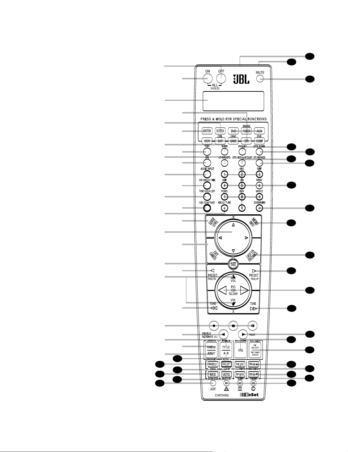
33
34
35
36
37
38
39
40
41
42
43
44
45
46
47
48
49
50
51
52
53
54
55
31
32
30
28
29
a
c
e
g
i
k
m
o
q
s
u
w
y
`
b
d
f
h
j
l
n
p
r
t
v
x
z
24
CVR700R2 REMOTE CONTROL FUNCTIONS
0
Power Off (All)
1
Power On (All)
2
LCD Information Display
3
Input Selectors
4
Screen Selector
5
System Selector
6
Surround Mode Selector
7
Test Tone Button
8
Logic 7 Mode/Sports Preset Button
9
SPL Select Button
A
Audio Input Selector
B
Direct/Brightness/Window Button
C
Tone Mode/Color/List Button
D
OSD/Contrast Button
E
Angle/Tuning Mode Button
F
Level/Guide Button
G⁄/¤/‹/› Navigation Disc
H
Exit/Cancel Button
I
Set Button
J
Preset/Page Down/Reverse Skip
Button
K
Volume Up/Down Control
L
Tuning Down/Reverse Search Button
M
Record/Stop/Pause Transport
Controls
N
Status/Settings/Button
O
Title/Freeze Button
P
Random/Letterbox Button
Q
Repeat/Frame Button
R
A-B/Auto Button
S
Program/PVR Replay Button
T
Disc Skip/PVR List Button
U
Audio/Screen Saver Button
V
Subtitle/TV/Video Button
W
Light Button
X
Macro/A/B/C Buttons
Y
Sleep/PIP Move Button
Z
Night Mode/PIP Channel Down
Button
a Disc Direct/PVR Live Button
b Remote Menu/PIP Channel Up
Button
c DVD Setup/PIP On-Off/PIP Swap
Button
d JBL On Screen Library™/Favorite
Button
e Play Transport Control Button
f Tuning Up/Forward Search Button
g Channel/Slow Play Up/Down
Control
h Preset/Page Up/Forward Skip Button
i Last Channel/Distance Button
j Screen Setup/Disc Menu/Info Button
k Zoom/Memory Button
l Alphanumeric Keys
m Stereo Mode/Movies Preset Button
n DTS Neo:6 Mode/Broadcast Preset
Button
o DTS Digital Surround Mode Button
p Dolby Surround Mode Button
q Mute Button
r EzSet Microphone Sensor
s IR Transmitter/Receiver
Page 25

CVR700R2 REMOTE CONTROL FUNCTIONS
40
41
484950515253545556
57
38
39
40
41
37
36
35
34
33
32
31
37
36
35
34
33
32
48
49
50
51
47
46
45
44
43
42
6
4
0
41
484950515253545556
57
38
3
9
40
41
37
36
35
34
33
32
31
37
36
35
34
33
32
48
4
9
50
51
47
46
45
44
43
42
6
01112
3334353
6
50515253545556
57
38
39
40
41
31
37
36
35
34
33
32
48
49
50
51
47
46
45
44
43
42
6
34353
6
383940
41
4647484950515253545556
57
38
39
40
41
25
24
23
22
21
20
3
7
36
3
5
34
33
32
31
37
36
35
34
33
32
48
49
50
51
47
46
45
44
43
42
6
50515253545556
57
38
39
40
41
31
37
36
35
34
33
32
48
49
50
51
47
46
45
44
43
42
6
16171
8
22232
4
40
41
484950515253545556
57
38
39
40
41
37
3
6
35
34
33
32
31
37
36
35
34
33
32
48
49
50
51
47
46
45
44
43
42
6
2728293
0
50
5
1
52
5
3
54
5
5
56
5
7
38
39
40
41
31
37
36
35
34
33
32
48
49
50
51
47
46
45
44
43
42
6
383940
41
4
6
47
4
8
49
5
0
51
5
2
53
5
4
55
5
6
57
38
39
40
41
25
24
23
22
21
20
37
36
35
34
33
32
31
37
36
35
34
33
32
48
49
50
51
47
46
45
44
43
42
6
IMPORTANT NOTE: The JBL Cinema
Vision remotes are powerful devices
capable of controlling virtually your entire
home cinema system. In comparison to a
traditional system of the same capabilities, these remotes can replace up to 10
separate remote controls and therefore
end the confusion and clutter associated
with having a different remote for each
of your system components. In order to
achieve this goal, the JBL Cinema Vision
remotes are designed to assume the
duties of controlling different devices
within your system by first pressing one
of the 10
buttons places your remote control in a
different “page”, where the remote buttons are assigned control functions available for that specific purpose. For example, all internal DVD changer functions
are accessed by pressing the
Button
Plasma Display functions are accessed
by pressing the
first, and all overall audio and system
commands for the CVR700 are accessed
by first pressing the
see references to the system being active
in DVD, SYSTEM, SCREEN, CABLE/SAT,
or other modes. This means that one of
these 10 keys is to be pressed first to
place your remote in the prescribed mode
before accessing any specific controls. It
is important to always remember to press
the appropriate page selection button
before trying to access any specific functions for a system or source. This may
take a little bit of discipline and practice
at first, but it should become second
nature in a very short time.
NOTES:
The function names shown here are
•
each button’s function when used with
the CVR700 (System), its internal DVD
changer (DVD/Main) and the CVPD50
(Screen). Most buttons have additional
functions when used with other
devices, and some of these functions
may be assigned to different buttons,
depending on which device was selected. The device name will appear in the
upper line of the
Display
assigned to that device will appear in
the lower line when the button is
pressed. See pages 89 through 91 for a
list of the functions assigned to each
button for each device type.
Selector Buttons dfg
. Pressing one of these
DVD
d first, and all CVPD50
Screen Button e
System Button f
. Throughout this manual, you will
LCD Information
2 and the function
• Some buttons have special functions
when they are pressed and held for 3
seconds.
• The jack on the upper right side of the
remote is reserved for future use. Do
not remove the plug provided or connect any device to the jack.
To make it easier to follow the instruc-
•
tions that refer to this illustration, a
larger copy may be downloaded from
the Product Support section for this
product at www.jbl.com.
• The JBL Cinema Vision main remote
control may be programmed to control
up to eight devices, including the
CVR700 receiver with disc changer and
the CVPD50 screen. Before using the
remote, it is important to press the
Input Selector 3 that corresponds
to the device you wish to operate.
• The remote is capable of operating a
wide variety of products made by other
manufacturers using control codes that
are programmed into the remote’s code
library. As described on pages 76–78,
it is simple to program the remote to
operate your device by selecting the
device type and brand, and then programming the correct set of codes for
that brand.
0 Power Off (All): Press this button
to place the CVR700 (and the CVPD50) or
a selected device in the Standby mode.
Press and hold this button to place all
devices, including the CVR700, the
CVPD50 and any other products whose
codes you have programmed into the
remote, into the Standby mode.
1 Power On (All): Press this button
to power on the CVR700 (and CVPD50)
or
another device you selected by first pressing the appropriate
Input Selector 3.
Press and hold this button to power on
all devices, including the CVR700, the
CVPD50 and any other products whose
codes you have programmed into the
remote.
2 LCD Information Display: This
two-line screen displays various informa
tion depending on the commands that
have been entered into the remote.
Normally, the upper line will display the
current device (e.g.,
DVD/MAIN), and
the lower line will display the name of
the function key when pressed (e.g.,
DISC SKIP). See page 85 for information on renaming devices and keys.
3 Input Selectors: Pressing one of
these buttons will perform two actions.
The CVR700 will switch to the source
selected, and the remote will switch to
the control codes for the selected source.
In order to control the CVR700 again,
press the
System Selector 5, and to
control the CVPD50 screen, press the
Screen Selector 4.
Press and hold any of these buttons to
power on the CVR700, the CVPD50 and
the source device, and to begin play of
the source device.
4 Screen Selector: Press this button
to select the control codes for the
CVPD50 screen.
5 System Selector: Press this button
to select the control codes for the CVR700.
6 DSP Surround Mode Selector: In
System mode, press this button to select
one of the DSP audio surround modes,
such as Hall 1, Hall 2 or Theater. Each
press of the button selects another mode.
See page 62 for descriptions of the various surround modes.
7 Test Tone Button: Press this button
to activate the CVR700’s test tone that is
used to calibrate speaker output levels.
See pages 50–51 for more information on
calibrating speaker output levels.
8 Logic 7 Mode/Sports Preset
Button:
When the System Selector
5 is active, press this button to select
from among the available Logic 7 surround modes. (See page 62 for descrip
tions of the various surround modes.)
When the
Screen Selector 4 is
active, press this button to select the
CVPD50 picture settings that were preset
at the factory for optimal viewing of
sporting events.
NOTE: The Sports/Broadcast/ Movies
Buttons
imn optimize pic
settings for a specific viewing medium.
The Broadcast settings are the most neutral, balanced and accurate, and are optimized for clarity
. The Movies settings are
softer and less bright. The Sports settings
are more vibrant and optimized for fastmoving action.
-
9 SPL Select Button: This button
activates the EzSet function to quickly
and accurately calibrate the speaker out
put levels. The EzSet remote also has a
manual SPL meter function to assist with
manual setting of the output levels, or
trimming the settings to an external
source. See page 51 for more information
on EzSet.
-
ture
-
25
Page 26

52
5
3
54
5
5
56
5
7
38
39
40
41
48
49
50
51
47
46
45
44
43
42
6
40
41
48
4
9
50
5
1
52
5
3
54
5
5
56
5
7
38
39
40
41
3
7
36
3
5
34
33
32
31
37
36
35
34
33
32
48
49
50
51
47
46
45
44
43
42
6
5253545556
57
38
39
40
41
48
49
50
51
47
46
45
44
4
3
42
6
111
2
232
4
293
0
40
41
484950515253545556
57
38
39
40
41
37
3
6
35
3
4
33
3
2
3
1
37
36
35
34
3
3
32
48
49
50
51
47
46
45
44
4
3
42
6
01112
2122232
4
2728293
0
52
5
3
54
5
5
56
5
7
38
39
40
41
48
49
50
51
47
46
45
44
43
4
2
6
232
4
293
0
40
41
48
4
9
50
5
1
52
5
3
54
5
5
56
5
7
38
39
40
41
37
36
35
34
33
32
31
37
36
35
34
33
3
2
48
49
50
51
47
46
45
44
43
4
2
6
2122232
4
2728293
0
56
57
48
49
50
51
6
26
A Audio Input Selector: Press this
button to select one of the digital audio
9)cdefhijk for
inputs
use with its source or to select the analog
audio input for that source. It is not possible to reassign a digital audio input to
another source. See page 60 for more
information on using digital inputs.
B Direct/Brightness/Window
Press this button when the tuner
Button:
is in use to directly enter a station’s frequency, or when a CD is in use to directly
enter a track number. After pressing this
button, press the appropriate
numeric Keys
l to select a station
Alpha-
or track.
When the Screen mode is active, press
this button to adjust the brightness of
the CVPD50. Use the
Controls
q to increase or decrease
‹/› Navigation
the brightness setting.
See page 55 for more information on
screen adjustments. This button also
activates the Window function for TiVo
players. See your TiVo owner’s manual
for more information on the Window
function.
C Tone Mode/Color/List Button:
This button controls the tone settings,
enabling adjustment of the bass and treble boost or cut. You may also use it to
disable the tone controls, for a “flat”
response. The first press of the button
displays a
TONE IN message in the
Lower Display Line E and on-screen
display. To disable the controls, press the
⁄/¤ Navigation Controls G until
OUT
the display reads
TONE
. T
o
change the bass or treble settings, press
this button again until the desired control
appears in the
Lower Display Line E
and in the on-screen display, and then
press the
⁄/¤ Navigation Controls
G until the desired setting appears.
When the Screen mode is active, press
this button to adjust the color temperature of the CVPD50 display. See page 55
for more information on screen adjust
ments. This button also activates the List
function for TiVo players. See your TiVo
s manual for more information on
owner’
the List function.
D OSD/Contrast Button: Press this
button when the System mode is active
to access the setup menu for the
s audio functions. When the
CVR700’
Screen mode is active, press this button
to adjust the contrast of the CVPD50 dis-
. See page 55 for more information on
play
screen adjustments.
E Angle/Tuning Mode Button: When
the DVD mode is active, press this button
so select an alternate camera angle, if
available on the current DVD.
When the tuner is in use, press this button to change the tuner scan mode
between manual and automatic. When
the button is pressed so that
AUTO
appears in the Lower Display
E, only stations with acceptable
Line
TUNE
signal quality will be tuned when scanning, and the tuner will play FM stations
in stereo, when available. In the Auto
uning Up/Down
mode, when the
Buttons
T
8Lf are pressed
and held, the unit will automatically
search for the next available station with
good signal strength. When the
Mode Button
TUNE
o is pressed so that
MANUAL
appears in the
Tuning
Lower Display Line E, pressing and
holding the
Tuning Up/Down Buttons
8Lf will cause the tuner to
scan up or down through the frequencies
and stop when the button is released,
even if that frequency does not provide
an acceptable signal. In either
AUTO
or TUNE MANUAL mode,
each tap of the
Buttons
Tuning Up/Down
8Lf will cause the
TUNE
tuner to step through the frequencies in
single-step increments.
When the FM band is in use, pressing the
button so that the
TUNE MANUAL
mode is activated will enable you to tune
stations with weak signals by changing
to monaural reception. See page 64 for
more information on tuner operation.
F Level/Guide Button: This button is
used to start the process of setting the
CVR700’s output levels to an external
source, such as a favorite DVD. While
the source is playing, press this button,
and then press the
Controls
G until the channel to adjust
appears. Press the
⁄/¤ Navigation
Set Button I to
select that channel, and then use the
⁄/¤ Navigation
Controls
G again
to adjust the level setting. See page 64
for more information.
G ⁄/¤/‹/› Navigation Disc:
This single disc-like button is used to nav
igate the on-screen configuration menus,
to scroll through options lists and to
select various settings such as delay,
speaker configurations, surround modes,
digital inputs, etc. To use the button, simply press it left, right, up or down in the
direction indicated by the
⁄/¤/‹/›
icons printed on the disc.
H Exit/Cancel Button: When programming the remote, press this button
to cancel the current function and return
to the previous remote function. When
using the remote to enter frequencies for
direct tuner access or track numbers for
direct access on a CD, press this button
to clear previous entries.
I Set Button: This button is used to
enter settings into the CVR700’s memory,
or to confirm a selection while setting
delay distances, speaker configuration
and output level adjustments. It is used
as the Enter or OK button for most other
devices.
J Preset/Page Down/Reverse Skip
Button:
This multipurpose button has a
different function depending on the
source in use.
When used with the tuner, this button
scrolls through the preprogrammed station presets.
When used with optical sources, such as
the internal disc changer or an external
CD player, press this button once to
return to the beginning of the current
track, and again quickly to go to the
beginning of the previous track.
The Page Down function is used with
cable and satellite television to page
quickly through on-screen menus.
When a disc containing JPEG still images
is being played using the internal changer,
press this button to scroll to the previous
image.
olume Up/Down Controls: To
K V
raise the volume, press towards the top
of the disc, where it is marked
and to lower the volume, press towards
the bottom of the disc, where it is marked
¤ Vol. The left and right arrows on this
disc have different functions, depending
on the source in use. See
Play Up/Down Control
Channel/Slow
g below for
more information.
uning Down/Reverse Search
L T
Button:
This button has different functions depending on whether the tuner or
another source is in use.
Press this button when the tuner is in use
to change the station to one with a lower
frequency
. Each tap of this button will
decrease the frequency by one increment.
When the tuner receives a strong enough
signal for adequate reception, MANUAL
TUNED will appear in the Lower
Display Line
E. When the tuner is in
the Auto/Stereo mode, press and hold the
button to cause the tuner to scan for the
⁄ V
ol,
Page 27

next lower station with acceptable signal
strength and stop. The
E will indicate AUTO TUNED.
Line
Lower Display
When an FM Stereo station is tuned, the
display will read
AUTO ST TUNED.
When the tuner is in Manual/Mono mode,
you may press and hold this button to
scan downward through the frequencies,
and the tuner will stop immediately
when you release this button, even if no
acceptable signal is detected at that
frequency
.
See page 64 for more information on
using the tuner.
When an optical player source, such as
the internal DVD changer, is in use, press
this button to search quickly in reverse
through the current track or chapter.
Depending on the type of disc used in the
internal DVD changer, each additional
press will cycle through the available
scan speeds as follows (available scan
speeds may differ for external optical
source devices):
DVD-Audio and DVD-Video discs: 2x, 4x,
16x, 100x
CD and VCD discs: 2x, 4x, 8x
MP3 and WMA discs: 2x, 4x, 8x, 16x
See page 68 for more information on
using the internal DVD changer’s transport controls.
M Record/Stop/Pause Transport
Controls:
These buttons have no function in the System or Screen modes, but
are used with sources such as the internal disc changer or external DVD or CD
players, tape or digital recorders or VCRs.
When the internal disc changer is in use,
pressing the Stop button once will place
a DVD in resume mode, meaning that you
may press the
Play Button e to con-
tinue playing the disc from the point
where it was stopped. If you press the
Stop button twice, play will resume from
the beginning of the disc. Pressing the
Pause Button w will pause play
,
allowing you to step frame by frame forward through a DVD with each additional
press of the
the
play
Pause Button w. Press
Play Button e, to resume normal
, or press the
Stop Button w to
stop.
N Status/Settings Button: This but-
ton has different functions, depending on
which device is in use.
Press it to display the CVR700 system’
s
status, or an external DVD recorder’s
status.
When the internal disc changer or tuner,
or an external cable television box is in
use, press this button to access the current settings for the device.
For digital VCRs and game consoles, this
button performs the Back function. For
some PVRs/DVRs this button performs
the Instant Replay function.
O Title/Freeze Button: This button’s
function differs, depending on whether
the internal disc changer (DVD/Main
mode) or the Screen mode is active. To
use this button, be careful to press only
on the upper portion of the button, as
other functions are accessed by pressing
on the lower portion of the button.
In DVD/Main mode, press this button
while a disc is playing to display the current title number. Press it again to jump
to the next numbered title on the disc.
This function may be available even
when the disc’s software prohibits titlejumping using the
Skip Buttons
Forward/Reverse
Jh. Many DVD-Audio
discs require you to press this button to
access the disc menu.
In Screen mode, you may use this button
to pause playback of the video picture
while allowing the audio playback to continue uninterrupted, enabling you to capture an instance or frame of the video.
P Random/Letterbox Button: This
button’s function differs, depending on
whether the internal disc changer
(DVD/Main mode) or the Screen mode is
active. To use this button, be careful to
press only on the upper portion of the
button, as other functions are accessed
by pressing on the lower portion of the
button.
In DVD/Main mode, press this button for
playback in random order. The Random
function is not available when playing
DVD-Audio or DVD-Video discs unless a
playlist has been programmed, and it is
not available at all for JPEG discs.
In Screen mode, when using the internal
DVD changer, this button is only active if
the Auto Resize feature is turned off via
the SCREEN MENU (see page 57). This
button performs the Letterbox function,
which enables you to adjust the screen to
eliminate black bars that may appear on
the top and bottom or sides of the image
due to the aspect ratio of the program
material differing from the 16:9 aspect
ratio of the CVPD50. In most cases, the
CVR700’s video processor is able to automatically detect the aspect ratio setting
of the program material and adjust the
display automatically to fill the screen.
However, in some cases the material may
be a movie displayed in
(2.35:1) format, or the material
widescreen
may not
contain embedded information necessary
for the CVR700 to make an automatic
adjustment. The available letterbox
modes are:
16:9 – This setting is used to display 16:9
program material in the full-screen 16:9
mode on the CVPD50. This setting will
also apply a linear (consistent) stretch to
a 4:3 picture.
4:3 LTRBOX TO 16:9 – This mode is used
to adjust an image which is designed to
display a 16:9 movie on a 4:3 screen. In
order to preserve the full width of the
movie on a narrower screen, the image
is reduced in size and black bars appear
above and below it. This setting zooms
in on the image, enabling it to fill the
CVPD50’s 16:9 screen without losing any
portion of the image. The image is simply
enlarged so that its two sides fit the
edges of the CVPD50 16:9 screen and the
black bars on top and bottom are cropped
off. The image is stretched in a linear
fashion (evenly throughout the frame).
2.35 LB TO 16:9 NL – This mode is used
to adjust an image from a widescreen
film which is actually at a wider ratio
than the CVPD50’s 16:9 ratio. In order to
fit on the smaller screen, the image is
compressed in a nonlinear fashion, but no
portion of the image is lost.
2.35 LB TO 16:9 CROPPED – This mode
is an alternative adjustment for a
widescreen film. The image is not compressed or scaled in any way, but the
outer edges are cropped, sacrificing a
slight amount of the original content in
exchange for 100% accurate image proportions.
4:3 HDTV TO 16:9 – As HDTV is new to
the broadcast industry and there is still a
considerable amount of older 4:3 standard recording and broadcast equipment
in use, 4:3 material is sometimes broadcast in HD 16:9 format with black or
other color bars on its sides. Since these
bars are a part of the actual picture, con
ventional picture resizing techniques do
not work in eliminating them. This setting
is specifically designed to address this
problem. It first crops the bars off the
sides of the 16:9 picture to render it a 4:3
picture, and then performs a natural-looking nonlinear stretch to fill the entire 16:9
screen.
-
27
Page 28

The Letterbox adjustment is temporary
and will only apply to that disc. We
encourage you to experiment with the
modes to find one that suits you for a
given presentation.
Additional aspect ratio adjustments are
available using the
Frame Button Q.
Q Repeat/Frame Button: This but-
s function differs depending on
ton’
whether the internal disc changer (DVD/
Main mode) or the Screen mode is active.
To use this button, be careful to press
only on the lower portion of the button,
as other functions are accessed by press
ing on the upper portion of the button.
In DVD mode, pressing this buttons
accesses the Repeat functions. You may
repeat a chapter, track, title, disc, file or
programmed playlist. For JPEG discs, you
may repeat one file or one folder, but the
repeat disc function is not available.
In Screen mode, when using the internal
DVD changer, this button is only active if
the Auto Resize feature is turned off via
the SCREEN MENU. This button performs
the Frame function, which enables you to
set the desired aspect ratio for viewing
program materials, independent of the
aspect ratio encoded on the disc. The
following settings are available:
16:9 – This setting is used to display 16:9
program material in the full-screen 16:9
mode on the CVPD50.
4:3 TO 16:9 NL – This mode adjusts a 4:3
aspect ratio image to fill the CVPD50’
s
6:9 screen while creating a more naturallooking picture. This is accomplished by
stretching the two sides of the picture
more than the center of the picture where
most of the content is.
4:3 LTRBOX TO 16:9 – This mode is used
to adjust an image which is designed to
display a 16:9 movie on a 4:3 screen. In
order to preserve the full width of the
movie on a narrower screen, the image
is reduced in size and black bars appear
above and below it. This setting zooms
in on the image, enabling it to fill the
s 16:9 screen without losing
CVPD50’
any portion of the image. The image is
simply enlarged so that its two sides fit
the edges of the CVPD50 16:9 screen and
the black bars on top and bottom are
cropped off.
2.35 LB TO 16:9 NL – This mode is used
to adjust an image from a widescreen
film which is actually at a wider ratio
than the CVPD50’s 16:9 ratio. In order to
fit on the smaller screen, the image is
28
compressed, but no portion of the image
is lost.
2.35 LB TO 16:9 CROPPED – This mode
is an alternative adjustment for a
widescreen film. The image is not compressed or scaled in any way
outer edges are cropped, sacrificing a
slight amount of the original content in
exchange for 100% accurate image proportions.
4:3 HDTV TO 16:9 – As HDTV is new to
the broadcast industry, and there is still
a lot of older 4:3 standard recording and
-
broadcast equipment in use, 4:3 material
is sometimes broadcast in HD 16:9 format with black or other color bars on its
sides. Since these bars are a part of the
actual picture, conventional picture resizing techniques do not work in eliminating
them. This setting is specifically designed
to address this problem. It first crops the
bars off of the sides of the 16:9 picture to
render it a 4:3 picture, and then performs
a natural-looking nonlinear stretch to fill
the entire 16:9 screen.
4:3 – This mode may be used with programs that are known to be in the 4:3
aspect ratio. The image’s original aspect
ratio is preserved unaltered, and black
bars will appear on the left and right
sides of the image to fill the CVPD50’s
16:9 aspect ratio screen.
The difference between the Frame and
Letterbox functions is that the Frame
function allows access to the 4:3 and
4:3 TO 16:9 NL modes, which are mainly
useful for materials originating in the
4:3 format.
NOTE:The Letterbox and Frame func
tions are not available with the internal
DVD/CD changer unless the DVD Auto
Resize function has been turned off using
the screen setup menus. See page 57 for
more information.
R A-B/Auto Button: This button’
function differs depending on whether
the internal disc changer (DVD/Main
mode) or the Screen mode is active. To
use this button, be careful to press only
on the lower portion of the button, as
other functions are accessed by pressing
on the upper portion of the button.
In the DVD mode, press this button once
to select the beginning (point A), and
again to select the end (point B) of a passage you wish to play repeatedly. Press
the button again to end repeat playback.
A-B repeat play is not available for VCD,
MP3, WMA or JPEG discs.
, but the
In the Screen mode, this button selects
automatic detection of the aspect ratio of
program material from external sources,
with playback in the 16:9 format. It will
display 4:3 images stretched to fill the
16:9 screen. This function is not available
with HD (480p or better) signals. If the
4:3 image is in letterbox format, with
bars at the top and bottom of the screen,
those bars will remain. See pages 13 and
27 for more information on configuring
aspect ratios.
S Program/PVR Replay Button: In
the DVD/Main mode, press this button
to access the screen for programming
playlists. When a PVR (personal video
recorder) is in use, press this button for
replay of recorded materials. Refer to
your PVR’s owner’s manual for more
information.
T Disc Skip/PVR List Button: In the
DVD/Main mode, press this button to
begin play of the next available disc in
the changer. When a PVR is in use, press
this button to list recorded materials.
Refer to your PVR’s owner’s manual for
more information.
U Audio/Screen Saver Button: This
button has different functions depending
on whether it is pressed in DVD/Main
mode or Screen mode.
In DVD/Main mode, pressing this button
accesses the available audio soundtracks
on a DVD. In some cases, the disc may
simply contain different languages. Other
discs may switch the audio format: e.g.,
to linear PCM or Dolby Digital 5.1.
Pressing this button may sometimes pro-
-
vide access to commentary soundtracks.
In Screen mode, pressing this button
places the CVPD50 display in Screen
Saver mode, in which a JBL logo will
appear to move around the screen.
It is
important to turn on the Screen Saver
s
any time a still image is likely to remain
on screen for more than a few minutes,
because a still image, such as a menu
, may be “burned” into the display
display
,
causing permanent damage to the plasma
screen that is not covered under warranty.
This danger is not present when a moving
image is displayed.
V Subtitle/TV/Video Button: This
button has different functions depending
on whether it is pressed in DVD/Main
mode or Screen mode.
In DVD/Main mode, press this button to
select a subtitle language or to turn sub
-
titling off.
Page 29

In Screen mode, or when used with a
video source device that is used for obtaining television broadcasts, such as a
cable box, satellite receiver
, TiVo, PVR,
DVR or VCR, this button allows you to
select between the television signal or
one of the device’s video inputs. See the
s owner’s manual for more infor-
device’
mation on the use of this function.
W Light Button: Press this button to
activate the remote’s backlight for ease
of use in darkened rooms. The light will
remain active for 7 seconds after this button has been pressed, and will remain lit
for an additional 7 seconds after any
other button on the remote has been
pressed.
X Macro/A/B/C Buttons: Press these
buttons to store or recall a “Macro”, a
sequence of commands that you may program into the remote. See page 80 for
more information on programming and
using macros. These buttons have unique
functions when used with game consoles, cable TV boxes and PVRs. See the
owner’s manual for the appropriate
device for further information.
Y Sleep/PIP Move Button: This button has different functions depending on
which device is in use when it is pressed.
In the System mode, the Sleep function
is activated to automatically place the
CVR700 and CVPD50 in Standby mode
after a period of time. Each press of the
button changes the time until turn-off: 90
minutes, 80 minutes, 70 minutes, 60 minutes, 50 minutes, 40 minutes, 30 minutes,
20 minutes, 10 minutes, Sleep mode Off,
and then cycling back to 90 minutes, and
so forth. When the Sleep timer is in use,
the front-panel displays will dim to half
brightness.
In the Screen mode, this button places
the CVPD50 display in Standby mode,
without affecting use of the CVR700. This
function may be preferred for audio-only
listening sessions to prevent burning the
plasma display.
When a composite video output from a
PIP-capable device, such as a cable box,
has been connected to the
Picture Composite V
Picture-in-
ideo Input
a,
pressing this button enables you to move
the PIP inset display around the CVPD50
screen, using the
⁄/¤/‹/ ›
Navigation Disc q.
Z Night Mode/PIP Channel Down
Button:
This button’s function differs
depending on the device in use when
it is pressed.
When pressed in the System mode, this
button activates the Night mode, preserving dialogue (center-channel) intelligibility
at low volume levels when available in
specially encoded Dolby Digital sources.
When used with a compatible device
whose video output has been connected
Picture-in-Picture Composite
to the
Video Input
a, it changes the channel
of the PIP device to the next lower one. It
has no effect on the CVR700 or CVPD50.
a Disc Direct/PVR Live Button: This
button’s function differs depending on
which device is in use when it is pressed.
In DVD/Main mode, press it, and then
press the numeric key corresponding to
the position number of the disc you wish
to play to immediately begin playback of
that disc.
When a PVR is in use, this button switches
to play of the signal currently being
received by the PVR. See the PVR’s
owner’s manual for more information.
b Remote Menu/PIP Channel Up
Button:
This button’s function differs
depending on whether it is pressed when
a picture-in-picture source is in use.
In System mode, this button accesses
the menu system for the remote control,
enabling you to program product codes,
use the EzSet speaker calibration system,
record macros, rename functions, and
perform other functions, as described
on pages 76 through 91.
When used with a compatible device
whose video output has been connected
to the
Picture-in-Picture Composite
Video Input
a, pressing this button
changes the channel of the PIP device to
the next higher one. It has no effect on
the CVR700 or CVPD50.
c DVD Setup/PIP On-Off/PIP Swap
Button:
This button’
s function differs
depending on whether it is used with the
internal DVD changer, or with a source
whose video output has been connected
Picture-in-Picture Composite
to the
Video Input
a.
When used with the DVD changer, this
button accesses the DVD setup menu
and enables you to configure the DVD
changer.
When used in Screen mode with a PIP
source connected, press this button once
to turn on the PIP function, and again to
turn it off. Pressing and holding this button for several seconds causes the main
source to appear in the PIP inset display
and the PIP source to appear in the main
display. Pressing and holding the button
again returns the PIP source to the inset,
and the main source to the main display
d JBL On Screen Library™/ Favorite
Button:
This button performs different
functions depending on whether it is
used with the internal DVD changer or
another source.
In DVD/Main mode, this button accesses
the JBL On Screen Library, which displays
on screen a thumbnail image and description of each disc currently loaded in the
CVR700’s internal changer, including disc
type and title if available. Use the
⁄/¤/‹/› Navigation Controls G
and the Set Button I to conveniently
select and play any loaded disc.
When used with cable television boxes or
satellite receivers, pressing this button
scrolls through your list of preprogrammed favorite channels.
e Play Transport Control Button:
This button is used with the internal DVD
changer or an external DVD player, VCR,
tape deck, digital recorder, CD player or
any other device with a transport mechanism to begin playback.
f Tuning Up/Forward Search
This button has different func-
Button:
tions depending on whether the tuner or
another source is in use.
Press this button when the tuner is in use
to change the station to one with a higher
frequency. Each tap of this button will
increase the frequency by one increment.
When the tuner receives a strong enough
signal for adequate reception, MANUAL
TUNED will appear in the Lower
Display Line
E. When the tuner is in
the Auto/Stereo mode, press and hold
the button to cause the tuner to scan for
the next higher station with acceptable
signal strength and stop. The
Display Line
TUNED
E will indicate AUTO
. When an FM Stereo station is
tuned, the display will read
TUNED
. When the tuner is in Manual/
Lower
AUTO
ST
Mono mode, you may press and hold this
button to scan upward through the fre
quencies, and the tuner will stop immediately when you release this button, even
if no acceptable signal is detected at that
frequency. See page 64 for more information on using the tuner.
,
.
29
Page 30

40
41
484950515253545556
57
38
39
40
41
37
36
35
34
33
32
31
37
36
35
34
33
32
48
49
50
51
47
46
45
44
43
42
6
30
When an optical player source, such as
the internal DVD changer, is in use, press
this button to search quickly forward
through the current track or chapter
.
Depending on the type of disc used in the
internal DVD changer, each additional
press will cycle through the available
scan speeds as follows (available scan
speeds may differ for external optical
source devices):
DVD-Audio and DVD-Video discs: 2x, 4x,
16x, 100x
CD and VCD discs: 2x, 4x, 8x
MP3 and WMA discs: 2x, 4x, 8x, 16x
See page 68 for more information on
using the internal DVD changer’s transport controls.
g Channel/Slow Play Up/Down
Control:
These controls use the ‹/›
icons on the same disc as the Volume
Up/Down Controls
K. The left and
right arrows have different functions,
depending on the source in use.
When a disc containing JPEG still images
is being played using an external disc
player, press the right side of this button
to advance to the next image on the disc
or the left side of this button to return to
the previous image. (When using the
internal changer, the
Buttons
Jh perform this function.)
Page Up/Down
When a cable television box, satellite
receiver, HDTV tuner or TiVO device is in
use, press the right side of this button to
tune in to the next higher channel, or the
left side to tune in to the next lower
channel.
When the internal DVD changer or an
external DVD player is in use and a DVD
is playing, press the right side of this button once to switch to the DVD slow for
ward play mode. Each additional press
of the right side of the button will cycle
through the available slow-play speeds of
1/2x, 1/4x and 1/8x. Pressing the left side
of the button switches to the DVD slow
reverse play mode. Additional presses of
the left side of the button cycles through
the available slow-play speeds of 1/2x,
1/4x and 1/8x. No slow-play speeds are
available for CDs or other disc types.
h Preset/Page Up/Forward Skip
Button:
This multipurpose button has
a different function depending on the
source in use.
When used with the tuner, this button
scrolls through the preprogrammed station presets.
When used with optical sources, such as
the internal disc changer or an external
CD player, press this button once to skip
to the beginning of the next track.
The Page Up function is used with cable
and satellite television to page quickly
through on-screen menus. When a disc
containing JPEG still images is being
played using the internal changer, press
this button to scroll to the next image.
i Distance/Last Channel Button:
This button’s function differs depending
on whether it is used in the System mode
or with another source.
In the System mode, this button is used
to enter the distance from each speaker
group to the listening position to avoid
unnatural sound caused by the speakers
being placed at varying distances from
the listener, which could result in delay
artifacts. When this button is pressed,
DIST FRONT 10FT will appear
Lower Display Line E, with
in the
FRONT and 10FT both flashing.
Press the
Set Button s to select
the front speaker group, and
will stop flashing. Use the ⁄/¤
Navigation Controls q to select the
desired distance, and press the
Button
s again to enter it. Use the
⁄/¤ Navigation Controls q to
scroll through the remaining speaker
groups:
CENTER, SIDE-S (side
surround) or
BACK-S (back surround –
this setting may only be available after a
6.1-channel bitstream has been detected;
for example, by playing a Dolby Digital
EX DVD).
When used with most video sources, this
button returns to the previously selected
broadcast channel.
-
j Screen Setup/Disc Menu/Info
Button:
This button is used in Screen
mode to access the setup menus to configure and adjust the CVPD50 display
screen. In DVD mode, this button access
es the menu on the current disc, enabling
you to select the main feature or accompanying featurettes for playback or make
other selections, depending on how the
disc is programmed.
k Memory/Zoom Button: When used
with the tuner, press this button to enter
the currently tuned radio station into a
desired preset location using the
Alphanumeric Keys l to select the
preset location between the numbers 01
and 30. Press this button a second time
to store your selection. To recall that sta-
, select the tuner as the source,
tion later
FRONT
Set
then either use the
Buttons
Jh to scroll to the desired
preset station, or use the
Keys
l to directly enter the preset sta
tion location.
In DVD/Main mode, this button may be
used while a DVD-Video disc is playing to
zoom the picture so that it is enlarged.
There are four steps to the zoom function,
each progressively larger. Continue pressing the button to cycle through the steps
and return to the normal view
on the disc, you may also be able to use
⁄/¤/‹/› Navigation Controls
the
G to view different areas of the
enlarged image.
l Alphanumeric Keys: Select numbers by pressing these keys. When
renaming functions or devices on the
remote, these keys may be used to
select letters.
m Stereo Mode/Movies Preset
This button’s function varies
Button:
depending on whether the System or
Screen mode has been selected.
In System mode, this button is used to
select a stereo listening mode. When the
button is pressed so that 2 CHANNEL
STEREO appears in the Lower
Display Line
and the DSP and
Surround Mode Indicators
you will enjoy a two-channel presentation of the sound along with the benefits
of bass management. Depending on
whether your system is configured for 5.1
or 6.1/7.1 channels, the next press of the
button will cause
then
7 CH STEREO to appear, and
the stereo signal will be routed to all five
(or seven) speakers. See page 62 for
more information on stereo playback
modes.
In the Screen mode, pressing this button
automatically adjusts the screen’s picture
-
settings to preprogrammed settings that
are recommended as optimal for viewing
movies.
NOTE: The Sports/Broadcast/ Movies
Buttons
imn optimize pic
settings for a specific viewing medium.
The Broadcast settings are the most neu
tral, balanced and accurate, and are optimized for clarity
softer and less bright. The Sports settings
are more vibrant and optimized for fastmoving action.
Preset Up/Down
Alphanumeric
. Depending
E and on-screen display,
Surround Off
G are lit,
STEREO
CH
5
and
ture
. The Movies settings are
-
-
Page 31

n DTS Neo:6 Mode/Broadcast
40
41
484950515253545556
57
38
39
40
41
37
36
35
34
33
32
31
37
36
35
34
33
32
48
49
50
51
47
46
45
44
43
42
6
Preset Button:
varies depending on whether the System
or Screen mode has been selected.
In System mode, this button is used to
select a DTS Neo:6 audio surround mode.
See page 62 for more information on the
available DTS Neo:6 options.
In the Screen mode, pressing this button
automatically adjusts the screen’
settings to preprogrammed settings that
are recommended as optimal for viewing
broadcast television programs.
NOTE: The Sports/Broadcast/ Movies
Buttons
settings for a specific viewing medium.
The Broadcast settings are the most neutral, balanced and accurate, and are optimized for clarity. The Movies settings are
softer and less bright. The Sports settings
are more vibrant and optimized for fastmoving action.
o DTS Digital Surround Mode
Button:
encoded digital source is playing, each
press of this button will scroll through the
available DTS audio surround modes. The
specific choice of modes will vary according to the type of encoding on the disc
and your system’s speaker configuration
(5.1-channel or 6.1/7.1-channel). See
page 62 for more information on DTS
modes.
p Dolby Surround Mode Button:
In System mode, this button is used to
select from the available Dolby audio sur
round modes. Each press of this button
will select one of the Dolby Pro Logic II
(available in 5.1-channel systems) or IIx
(available in 6.1/7.1-channel systems)
modes, Dolby 3 Stereo, or Dolby Digital
when a Dolby Digital-encoded source is
in use. Each press of this button will
scroll through the available modes. See
page 62 for more information on Dolby
modes.
q Mute Button: Press this button to
momentarily silence the CVR700. Press
it again, or use the
Control
r EzSet Microphone Sensor: The
microphone sensor that is used by the
EzSet system is behind the three slots
at the top of the remote control. When
using EzSet to calibrate the CVR700, be
certain that the slots are not covered.
See page 51 for more information
on EzSet.
This button’s function
imn optimize
In System mode, when a DTS-
olume Up/Down
V
K to restore audio.
s picture
picture
s IR Transmitter/Receiver: The
infrared emitters and receivers behind
the plastic lens at the top of the remote
communicate the remote codes to the
CVR700 and other programmed devices.
Be certain that the lens is not covered
when using the remote, and point the
lens toward the CVR700 for the best
results. In learning mode, the remote
receives IR codes to be learned through
a receiver behind the lens. See page 78
for more information on learning remote
codes.
NOTE: DO NOT remove the rubber plug
that is supplied to cover the jack on the
upper right side of the remote. The jack is
not active and is reserved for future use.
-
31
Page 32

50515253545556
57
38
39
40
41
31
37
36
35
34
33
32
48
49
50
51
47
46
45
44
43
42
6
40
41
484950515253545556
57
38
39
40
41
37
36
35
34
33
32
31
37
36
35
34
33
32
48
49
50
51
47
46
45
44
43
42
6
383940
41
4647484950515253545556
57
38
39
40
41
25
24
23
22
21
20
37
36
35
34
33
32
31
37
36
35
34
33
32
48
49
50
51
47
46
45
44
43
42
6
8 9 10 11 12
3637383940
41
44454647484950515253545556
57
38
39
40
41
25
26
27
28
29
30
24
23
22
21
20
31
37
36
35
34
33
32
31
37
36
35
34
33
32
48
49
50
51
47
46
45
44
43
42
1 2 3 4 5
6
7
8 9 10 11 12
13 14 15 16 17 18
19 20 21 22 23 24
25 26 27 28 29 30
31 32 33 34 35 36
37 38 39 40 41 42
56
57
48
49
50
51
6
5253545556
57
38
39
40
41
48
49
50
51
47
46
45
44
43
42
6
50515253545556
57
38
39
40
41
31
37
36
35
34
33
32
48
49
50
51
47
46
45
44
43
42
6
40
41
484950515253545556
57
38
39
40
41
37
36
35
34
33
32
31
37
36
35
34
33
32
48
49
50
51
47
46
45
44
43
42
6
383940
41
4647484950515253545556
57
38
39
40
41
25
24
23
22
21
20
37
36
35
34
33
32
31
37
36
35
34
33
32
48
49
50
51
47
46
45
44
43
42
6
8 9 10 11 12
3637383940
41
3
44
4
5
46
4
7
48
4
9
50
5
1
52
5
3
54
5
5
56
5
7
38
39
40
41
25
26
27
28
29
30
24
23
22
21
20
31
37
36
35
34
33
32
31
37
36
35
34
33
32
48
49
50
51
47
46
45
44
43
42
1 2 3 4 5
6
7
8 9 10 11 12
13 14 15 16 17 18
19 20 21 22 23 24
25 26 27 28 29 30
31 32 33 34 35 36
5
6
57
48
49
50
51
6
5
2
53
5
4
55
5
6
57
38
39
40
41
48
49
50
51
47
46
45
44
43
42
6
50515253545556
57
38
39
40
4
1
31
37
36
35
34
33
32
48
49
50
5
1
47
46
45
44
43
42
6
40
41
4
8
49
5
0
51
5
2
53
5
4
55
5
6
57
38
39
4
0
4
1
37
36
35
34
33
32
31
37
36
35
34
33
32
48
49
5
0
5
1
47
46
45
44
43
42
6
383940
41
4647484950515253545556
57
38
39
40
41
25
24
23
22
21
20
3
7
36
35
34
33
32
31
37
36
35
34
33
32
48
49
50
51
47
46
45
44
43
42
6
8 9 10 11 12
3637383940
41
244
45
4
6
47
4
8
49
5
0
51
5
2
53
5
4
55
5
6
57
3
8
3
9
4
0
4
1
1
2
0
25
2
6
27
2
8
29
30
24
23
22
21
20
31
3
7
36
3
5
34
33
32
31
37
36
35
34
33
32
4
8
4
9
5
0
5
1
47
46
45
44
43
42
1 2 3 4 5
6
7
8 9 10 11 12
13 14 15 16 17 18
19 20 21 22 23 24
25 26 27 28 29 30
5
6
57
4
8
4
9
5
0
5
1
6
5253545556
57
3
8
39
40
41
4
8
49
50
51
47
46
45
44
43
42
6
111
2
5
0
51
5
2
53
5
4
55
5
6
57
3
8
3
9
4
0
4
1
31
37
36
35
34
33
32
4
8
4
9
5
0
5
1
47
46
45
44
43
42
6
01112
40
41
484950515253545556
57
38
39
40
41
3
7
36
3
5
34
33
32
31
37
36
35
34
33
32
48
49
50
51
47
46
45
44
43
42
6
2122232
4
38
3
9
40
4
1
4647484950515253545556
57
3
8
39
40
41
2
5
24
2
3
22
2
1
20
37
36
3
5
34
33
32
31
37
36
35
34
33
32
4
8
49
50
51
47
46
45
44
43
42
6
8 9 10111
2
3
3637383940
41
44454647484950515253545556
57
3
8
39
40
41
2
5
26
27
2
8
29
30
2
4
23
22
2
1
20
31
37
36
3
5
34
33
32
31
37
36
3
5
3
4
33
32
4
8
49
50
51
47
46
4
5
4
4
43
42
1 2 3 4 5
6
7
8 9 10 11 12
13 14 15 16 17 18
19202122232
4
56
57
48
49
50
5
1
6
3
6
5253545556
57
38
39
40
41
48
49
50
51
47
4
6
45
4
4
43
42
6
50515253545556
57
38
39
40
41
31
37
3
6
3
5
3
4
33
32
48
49
50
51
47
4
6
4
5
4
4
43
42
6
40
4
1
484950515253545556
57
38
39
4
0
41
37
36
3
5
34
3
3
32
31
37
3
6
3
5
34
33
32
48
49
5
0
51
47
4
6
4
5
44
43
42
6
1516171
8
383940
41
4647484950515253545556
57
3
8
39
40
41
2
5
2
4
23
2
2
2
1
20
37
36
3
5
34
33
32
31
37
3
6
3
5
3
4
33
32
4
8
49
50
51
47
4
6
4
5
4
4
43
42
6
8 9 10 11 12
3
3637383940
41
2
3
4
4
4
5
4
6
4
7
4
8
4
9
5
0
5
1
5
2
5
3
5
4
5
5
5
6
5
7
3
8
3
9
40
41
2
9
2
5
26
27
2
8
29
30
2
4
23
22
2
1
20
31
37
36
3
5
34
33
32
31
37
36
3
5
3
4
33
32
4
8
4
9
50
51
47
46
4
5
4
4
43
42
1 2 3 4 5
6
7
8 9 10 11 12
13 14 15 16 17 18
5
6
57
48
4
9
50
51
7
2
6
5253545556
57
38
39
4
0
4
1
48
49
5
0
5
1
4
7
4
6
45
44
4
3
4
2
6
111
2
50515253545556
57
38
39
40
41
31
3
7
36
35
34
3
3
3
2
48
49
50
51
4
7
46
45
44
4
3
4
2
6
01112
40
41
48
4
9
50
5
1
52
5
3
54
5
5
56
5
7
38
39
40
4
1
3
7
36
35
3
4
33
32
3
1
3
7
36
35
34
33
3
2
48
49
50
5
1
4
7
46
45
44
43
4
2
6
3
8
39
4
0
41
4647484950515253545556
57
38
39
4
0
41
25
24
2
3
22
21
20
3
7
36
35
34
33
32
31
3
7
36
35
34
33
3
2
48
49
5
0
51
4
7
46
45
44
43
4
2
6
8 9 10 11 12
436
37
3
8
39
4
0
41
244
45
4
6
47
4
8
49
5
0
51
5
2
53
5
4
55
5
6
57
38
3
9
40
4
1
2
0
8
25
2
6
27
28
2
9
3
0
24
2
3
22
21
20
3
1
3
7
36
35
3
4
3
3
3
2
31
3
7
36
35
34
3
3
3
2
48
4
9
50
5
1
4
7
46
45
44
4
3
4
2
1 2 3 4 5
6
7
8 9 10 11 12
56
57
48
49
5
0
5
1
6
5
3
6
5253545556
57
3
8
39
40
41
4
8
49
50
51
47
46
4
5
4
4
43
42
6
5
0
5
1
5
2
5
3
5
4
5
5
5
6
5
7
3
8
3
9
40
41
3
1
37
36
35
3
4
33
32
4
8
4
9
50
51
47
46
45
4
4
43
42
6
40
41
4
8
4
9
5
0
5
1
5
2
5
3
5
4
5
5
5
6
5
7
3
8
3
9
40
41
37
36
3
5
3
4
33
32
3
1
37
36
3
5
3
4
33
32
4
8
4
9
50
51
47
46
4
5
4
4
43
42
6
383940
41
4
6
4
7
4
8
4
9
5
0
5
1
5
2
5
3
5
4
5
5
5
6
5
7
3
8
3
9
40
41
2
5
24
23
22
2
1
2
0
37
36
3
5
3
4
33
32
3
1
37
36
3
5
3
4
33
32
4
8
4
9
50
51
47
46
4
5
4
4
43
42
6
3
5
36
3
7
38
3
9
40
4
1
3
44
4
5
46
4
7
48
4
9
50
5
1
52
5
3
54
5
5
56
5
7
3
8
39
40
41
2
5
26
27
2
8
29
30
2
4
23
22
2
1
2
0
31
37
36
3
5
34
33
32
3
1
37
36
3
5
3
4
33
32
4
8
49
50
51
47
46
4
5
4
4
43
42
1 2 3 4 5
6
1
2
3
4
4
5
6
6
7
8
9
10
11
12
13
14
15
16
17
18
19
20
21
22
23
24
25
26
27
28
29
30
31
32
33
34
35
36
37
38
39
40
32
CVR700R1 REMOTE CONTROL FUNCTIONS
The CVR700R1 remote is capable of performing most of the same functions as the CVR700R2 remote control, which is intended mainly
for system setup, but is smaller and easier to handle on a day-to-day basis. The most noticeable functions missing from the CVR700R1
remote are the LCD information screen, and the EzSet speaker calibration function.
As it is a programmable, learning remote that is capable of controlling the source devices in your system, you will need to program it
separately from the CVR700R2 remote with the codes for your other components. It is already preprogrammed at the factory to control
your CVR700 and its internal disc changer, as well as the CVPD50 screen.
Power On (All)
uner/Auxiliary/VCR/CBL/SAT
DVD/T
Input Selectors
Sports, Broadcast and Movies
Preset Selectors
⁄/¤ Navigation Buttons
Level/DVD Setup/Guide Button
‹/› Navigation Buttons
Set Button
Exit/Cancel Button
Direct/Brightness/Window Button
Game/Digital Recorder/Computer
Input Selectors
Mute Button
Volume Up/Down Control
Disc Direct/Favorite Button
Alphanumeric Keys*
Angle/Tuning Mode (Tune-Manual)
Button
Screen Saver/Letterbox Button
PIP On-Off/PIP Swap Button
Auto/PIP Channel Up Button
Learn/Screen Standby/PIP Channel
Down Button
Light Button
Program/Record Button
Freeze/PVR List Button
Pause Button
Frame/Stop/PVR Live Button
Forward Play Button
Status/TV/V
Tuning Down/Reverse Search Button
Memory/Zoom Button
Tuning Up/Forward Search Button
Preset/Page Up/Down/Forward/
Reverse Skip Buttons
Disc Skip/Last Channel Buttons
Picture/Channel Up/Down and Slow
Play Forward/Reverse Button
System Selector
Screen Selector
Tone Mode/Color/List Button
OSD/Contrast Button
JBL On Screen Library™/
Settings/Distance Button
Menu/Info/Audio Input Selector
Power Off (All)
IR Transmitter/Receiver
ideo/PVR Play Button
The alphanumeric keys function as such for all devices except in System mode of the
*
CVR700, where pressing each key will access certain audio functions as follows:
1: Dolby Surround Mode Selector
2: DTS Digital Surround Mode Selector
3: DTS Neo:6 Surround Mode Selector
4: Logic 7 Surround Mode Selector
5: DSP Surround Mode Selector
6: Stereo Mode Selector
est Tone
7: T
8: No additional function
9: Night Mode
0: Sleep Timer
Page 33

IMPORTANT NOTE: The JBL Cinema
40
41
484950515253545556
57
38
39
40
41
37
36
35
34
33
32
31
37
36
35
34
33
32
48
49
50
51
47
46
45
44
43
42
6
50515253545556
57
38
39
40
41
31
37
36
35
34
33
32
48
49
50
51
47
46
45
44
43
42
6
40
41
484950515253545556
57
38
39
40
41
37
36
35
34
33
32
31
37
36
35
34
33
32
48
49
50
51
47
46
45
44
43
42
6
40
41
4
8
4
9
5
0
5
1
5
2
5
3
5
4
5
5
5
6
5
7
38
3
9
40
41
37
36
35
3
4
33
32
3
1
3
7
36
35
3
4
33
32
48
4
9
50
51
4
7
46
45
4
4
43
42
6
3
8
39
4
0
41
4647484950515253545556
57
38
39
4
0
4
1
25
24
2
3
2
2
21
20
3
7
3
6
35
34
33
3
2
31
3
7
36
35
34
3
3
3
2
48
49
5
0
5
1
4
7
46
45
44
4
3
4
2
6
8 9 10111
2
3
5
36
3
7
38
3
9
40
4
1
2
3
4
4
4
5
4
6
4
7
4
8
4
9
5
0
5
1
5
2
5
3
5
4
5
5
5
6
5
7
3
8
3
9
4
0
4
1
1
2
0
8
9
2
5
2
6
27
2
8
29
3
0
2
4
23
2
2
21
20
3
1
3
7
36
3
5
34
3
3
3
2
31
3
7
3
6
3
5
34
3
3
3
2
4
8
4
9
5
0
5
1
4
7
4
6
4
5
44
4
3
4
2
1 2 3 4 5
6
7
8 9 10 11 12
56
57
48
49
5
0
5
1
7
6
3
2
6
50515253545556
57
38
39
40
41
31
37
36
35
34
33
32
48
49
50
51
47
46
45
44
43
42
6
3637383940
41
44454647484950515253545556
57
38
39
40
41
25
26
27
28
29
30
24
23
22
21
20
31
37
36
35
34
33
32
31
37
36
35
34
33
32
48
49
50
51
47
46
45
44
43
42
1 2 3 4 5
6
7
8 9 10 11 12
50515253545556
57
38
39
40
41
31
37
36
35
34
33
32
48
49
50
51
47
46
45
44
43
42
6
5253545556
57
38
39
40
41
48
49
50
51
47
46
45
44
43
42
6
50515253545556
57
38
39
40
41
31
37
36
35
34
33
32
48
49
50
51
47
46
45
44
43
42
6
40
41
484950515253545556
57
38
39
40
41
37
36
35
3
4
33
32
3
1
37
36
35
34
33
32
48
49
50
51
47
46
45
44
43
42
6
4
0
4
1
484950515253545556
57
38
39
4
0
4
1
37
3
6
35
34
3
3
3
2
31
37
3
6
35
34
3
3
32
48
49
5
0
5
1
47
4
6
45
44
4
3
42
6
01112
2122232
4
40
41
4
8
4
9
5
0
5
1
5
2
5
3
5
4
5
5
5
6
5
7
3
8
3
9
40
41
37
36
35
3
4
33
32
3
1
37
36
35
3
4
33
32
4
8
4
9
50
51
47
46
45
4
4
43
42
6
50515253545556
57
38
39
4
0
4
1
31
37
3
6
35
34
3
3
32
48
49
5
0
5
1
47
4
6
45
44
4
3
42
6
01112
16171
8
22232
4
28293
0
34353
6
4
0
41
4
8
49
5
0
51
5
2
53
5
4
55
5
6
57
38
3
9
40
4
1
3
7
36
35
3
4
3
3
3
2
31
3
7
36
35
34
3
3
3
2
48
4
9
50
5
1
4
7
46
45
44
4
3
4
2
6
01112
1516171
8
2122232
4
2728293
0
3
8
39
4
0
41
4
6
4
7
4
8
4
9
5
0
5
1
5
2
5
3
5
4
5
5
5
6
5
7
38
3
9
40
41
25
24
2
3
22
21
20
3
7
36
35
3
4
33
3
2
31
3
7
36
35
34
3
3
3
2
48
4
9
50
51
4
7
46
45
44
4
3
4
2
6
5
0
51
5
2
53
5
4
55
5
6
57
3
8
3
9
40
41
3
1
3
7
36
35
3
4
33
32
4
8
4
9
50
51
4
7
46
45
4
4
43
42
6
383940
41
4
6
4
7
4
8
4
9
5
0
5
1
5
2
5
3
5
4
5
5
5
6
5
7
3
8
3
9
40
41
25
24
23
22
21
2
0
37
36
3
5
3
4
33
32
3
1
37
36
35
3
4
33
32
4
8
4
9
50
51
47
46
45
4
4
43
42
6
3637383940
41
44454647484950515253545556
57
38
39
40
41
25
26
27
28
29
30
24
23
22
21
20
31
37
36
35
34
33
32
31
37
36
35
34
33
32
48
49
50
51
47
46
45
44
43
42
1 2 3 4 5
6
40
41
4
8
49
5
0
51
5
2
53
5
4
55
5
6
57
38
3
9
40
41
3
7
36
35
3
4
33
32
3
1
3
7
36
35
34
33
3
2
48
4
9
50
51
4
7
46
45
44
43
4
2
6
01112
1516171
8
3334353
6
50515253545556
57
38
39
4
0
4
1
31
37
3
6
35
34
3
3
32
48
49
5
0
5
1
47
4
6
45
44
4
3
42
6
38
3
9
40
4
1
4647484950515253545556
57
38
39
40
4
1
25
2
4
23
2
2
2
1
20
37
3
6
3
5
34
3
3
3
2
31
37
3
6
35
34
3
3
32
48
49
50
5
1
47
4
6
45
44
4
3
42
6
5
0
5
1
5
2
5
3
5
4
5
5
5
6
5
7
3
8
3
9
40
41
3
1
37
36
3
5
3
4
33
32
4
8
4
9
50
51
47
46
4
5
4
4
43
42
6
01112
16171
8
28293
0
34353
6
40
41
4
8
4
9
5
0
5
1
5
2
5
3
5
4
5
5
5
6
5
7
3
8
3
9
40
41
37
36
3
5
3
4
33
32
3
1
37
36
3
5
3
4
33
32
4
8
4
9
50
51
47
46
4
5
4
4
43
42
6
01112
1516171
8
2728293
0
3334353
6
50515253545556
57
38
39
4
0
41
31
37
3
6
3
5
34
33
32
48
49
5
0
51
47
4
6
4
5
44
43
42
6
01112
3
8
3
9
4
0
4
1
4647484950515253545556
57
38
39
4
0
4
1
25
24
23
2
2
2
1
20
37
3
6
35
34
3
3
3
2
31
37
3
6
35
34
3
3
32
48
49
5
0
5
1
47
4
6
45
44
4
3
42
6
Vision remotes are powerful devices
capable of controlling virtually your entire
home cinema system. In comparison to a
traditional system of the same capabilities, these remotes can replace up to 10
separate remote controls and therefore
end the confusion and clutter associated
with having a different remote for each
of your system components. In order to
achieve this goal, the JBL Cinema Vision
remotes are designed to assume the
duties of controlling different devices
within your system by first pressing one
of the 10
buttons places your remote control in a
different “page
tons are assigned control functions available for that specific purpose. For example, all internal DVD changer functions
are accessed by pressing the
Button
Plasma Display functions are accessed
by pressing the
first, and all overall audio and system
commands for the CVR700 are accessed
by first pressing the
f . Throughout this manual, you
will see references to the system being
active in DVD, SYSTEM, SCREEN, CABLE/
SAT, or other modes. This means that one
of these 10 keys is to be pressed first to
place your remote in the prescribed mode
before accessing any specific controls. It
is important to always remember to press
the appropriate page selection key before
trying to access any specific functions for
a system or source. This may take a little
bit of discipline and practice at first, but
it should become second nature in a very
short time.
Each function on the CVR700R1 remote
has the same effect on the CVR700,
CVPD50 and other devices as described
earlier for the CVR700R2 remote control
functions; however, functions may be
combined on different keys. Each key has
an independent function depending on
the device currently in use. Be careful to
press the input selector
Screen mode selector
the device you wish to control prior to
pressing a button to be sure that your
button press will operate the desired
function. Refer to the function list on
pages 96 through 97 for information on
which function is assigned to a given key
for a given device.
Power On (All): Press this button
to power on the CVR700, the CVPD50 or
Selector Buttons dfg
. Pressing one of these
”, where the remote but-
DVD
d first, and all CVPD50
Screen Button e
System Button
, corresponding to
, or the System or
another device you selected by first
pressing the appropriate
Input Selector
.
Press and hold this button to place all
devices, including the CVR700, the
CVPD50 and any other products whose
codes you have programmed into the
remote, into the Standby mode.
DVD/Tuner/Auxiliary/VCR/CBL/
SAT Input Selectors:
Pressing one of
these buttons will perform two actions.
First, the CVR700 will switch to the
source selected. Then, the remote will
switch to the control codes for the selected
source. In order to control the CVR700
again, press the
System Selector ,
and to control the CVPD50 screen, press
Screen Selector .
the
Press and hold any of these buttons to
power on the CVR700, the CVPD50 and
the source device, and to begin play of
the source device.
Sports, Broadcast and Movies
Preset Selectors:
Selector
When the Screen
is active, press any of
these buttons to select the CVPD50 picture settings that were preset at the factory for optimum viewing of sporting
events, broadcast television programs or
movies.
NOTE: The Sports/Broadcast/ Movies
Buttons
imn optimize pic
ture
settings for a specific viewing medium.
The Broadcast settings are the most neutral, balanced and accurate, and are optimized for clarity. The Movies settings are
softer and less bright. The Sports settings
are more vibrant and optimized for fastmoving action.
⁄
/¤Navigation Buttons: These
buttons are used to navigate the onscreen configuration menus, to scroll
through options lists and to select various
settings such as delay, speaker configurations, surround modes, digital inputs, etc.
Level/DVD Setup/Guide Button:
This button is used to start the process of
setting the CVR700’s output levels to an
external source, such as a favorite DVD.
While the source is playing, press this
⁄
¤
button, and then press the
/
Navigation Controls until the
channel to adjust appears. Press the
Set Button to select that channel,
and then use the
Controls
⁄
/¤Navigation
again to adjust the
level setting. See page 64 for more
information.
In DVD mode, this button accesses the
DVD setup menu described on page 53,
and enables you to configure the DVD
.
changer
‹/›
Navigation Buttons: These
buttons are used to navigate the onscreen configuration menus, to scroll
through options lists and to select various
settings such as delay, speaker configurations, surround modes, digital inputs, etc.
Set Button: This button is used to
enter settings into the CVR700’s memory,
or to confirm a selection while setting
delay times, speaker configuration and
output level adjustments. It is used as
the Enter or OK button for most other
devices.
Exit/Cancel Button: When pro-
gramming the remote, press this button
to cancel the current function and return
to the previous remote function. When
using the remote to enter frequencies for
direct tuner access or track numbers for
direct access on a CD, press this button
to clear previous entries.
Direct/Brightness/Window
Button:
Press this button when the
tuner is in use to directly enter a station’s
frequency, or when a CD is in use to
directly enter a track number. After pressing this button, press the appropriate
Alphanumeric Keys l to select a
station or track.
When the Screen mode is active, press
this button to adjust the brightness of the
CVPD50. See page 55 for more information on screen adjustments. This button
also activates the Window function for
TiVo players. See your TiVo owner’s manual for more information on the Window
function.
NOTE: The Sports/Broadcast/ Movies
Buttons
imn optimize
picture
settings for a specific viewing medium.
The Broadcast settings are the most neutral, balanced and accurate, and are optimized for clarity
. The Movies settings are
softer and less bright. The Sports settings
are more vibrant and optimized for fastmoving action.
Game/Digital Recorder/
Computer Input Selectors:
Pressing
one of these buttons will perform two
actions. First, the CVR700 will switch to
the source selected. Then, the remote
will switch to the control codes for the
selected source. In order to control
the CVR700 again, press the
Selector
, and to control the
System
33
Page 34

50
5
1
52
5
3
54
5
5
56
5
7
38
39
40
41
31
3
7
36
3
5
34
33
32
48
49
50
51
4
7
46
4
5
44
43
42
6
5253545556
57
38
39
40
41
48
49
50
51
47
46
45
44
4
3
42
6
171
8
232
4
40
41
484950515253545556
57
38
39
40
41
37
36
35
3
4
33
3
2
3
1
37
36
35
34
3
3
32
48
49
50
51
47
46
45
44
4
3
42
6
1516171
8
2122232
4
5
2
5
3
5
4
5
5
5
6
5
7
3
8
3
9
40
41
4
8
4
9
50
51
47
4
6
4
5
4
4
43
42
6
111
2
171
8
232
4
40
41
4
8
4
9
5
0
5
1
5
2
5
3
5
4
5
5
5
6
5
7
3
8
3
9
40
41
37
36
3
5
3
4
33
32
3
1
37
3
6
3
5
3
4
33
32
4
8
4
9
50
51
47
4
6
4
5
4
4
43
42
6
01112
1516171
8
2122232
4
5
2
5
3
5
4
5
5
5
6
5
7
3
8
3
9
40
41
4
8
4
9
50
51
47
46
4
5
4
4
43
42
6
40
41
4
8
4
9
5
0
5
1
5
2
5
3
5
4
5
5
5
6
5
7
3
8
3
9
40
41
37
36
3
5
34
33
32
3
1
37
36
3
5
3
4
33
32
4
8
4
9
50
51
47
46
4
5
4
4
43
42
6
4
0
4
1
484950515253545556
57
3
8
3
9
40
4
1
3
7
36
3
5
3
4
33
32
3
1
37
36
3
5
3
4
33
32
4
8
4
9
50
5
1
47
46
4
5
4
4
43
42
6
01112
3
8
39
4
0
41
4647484950515253545556
57
38
39
4
0
41
25
24
23
22
21
20
3
7
3
6
35
34
33
32
31
3
7
36
35
34
3
3
3
2
48
49
5
0
51
4
7
46
45
44
4
3
4
2
6
8 9 10111
2
141516171
8
4
5
3
6
3
7
3
8
3
9
4
0
4
1
244
45
4
6
47
4
8
49
5
0
51
5
2
53
5
4
55
5
6
57
3
8
39
4
0
41
1
2
5
26
27
2
8
29
3
0
2
4
23
2
2
2
1
20
31
37
36
3
5
34
3
3
32
31
37
3
6
3
5
34
33
32
4
8
49
5
0
51
47
4
6
4
5
44
43
42
1 2 3 4 5
6
7
8 9 10111
2
13141516171
8
56
57
48
49
5
0
51
6
5
3
6
5
56
5
7
4
8
49
50
51
5
4
6
1
2
5253545556
57
38
39
4
0
4
1
48
49
5
0
5
1
4
7
4
6
45
44
4
3
4
2
6
111
2
5
0
51
5
2
53
5
4
55
5
6
57
3
8
3
9
40
41
31
37
36
35
34
3
3
3
2
4
8
4
9
50
51
47
46
45
44
4
3
4
2
6
16171
8
34
CVPD50 screen, press the Screen
Selector
.
Press and hold any of these buttons to
power on the CVR700, the CVPD50 and
the source device, and to begin play of
the source device.
Mute Button: Press this button to
momentarily silence the CVR700. Press
it again, or use the
Control
olume Up/Down
V
to restore audio.
Volume Up/Down Control: To raise
the volume, press towards the top of the
button (marked
⁄
); to lower the volume,
press towards the bottom of the button,
¤
where it is marked
.
Disc Direct/Favorite Button: In
DVD mode, press this button, and then
press the numeric key corresponding to
the position number of the disc you wish
to play to immediately begin playback of
that disc.
When used with cable television boxes or
satellite receivers, pressing this button
scrolls through your list of preprogrammed
favorite channels.
Alphanumeric Keys: Select num-
bers or letters by pressing these keys,
except in System mode (when operating
the audio section of the CVR700), in
which case each key has the following
functions:
1: Dolby Surround Mode Selector:
This button is used to select from the
available Dolby audio surround modes.
Each press of this button will select one
of the Dolby Pro Logic II (available in
5.1-channel systems) or IIx (available in
6.1/7.1-channel systems) modes, Dolby 3
Stereo, or Dolby Digital when a Dolby
Digital-encoded source is in use. Each
press of this button will scroll through the
available modes. See page 62 for more
information on Dolby modes.
2: DTS Digital Surround Mode
Selector:
When a DTS-encoded digital
source is playing, each press of this but
ton will scroll through the available DTS
audio surround modes. The specific
choice of modes will vary according to the
type of encoding on the disc and your sys-
s speaker configuration (5.1-channel
tem’
or 6.1/7.1-channel). When a DTS source is
not in use, this button has no function in
System mode. See page 62 for more
information on DTS modes.
3: DTS Neo:6 Surround Mode
Selector:
This button is used to select
a DTS Neo:6 audio surround mode. See
page 62 for more information on the
available DTS Neo:6 options.
4: Logic 7 Surround Mode Selector:
Press this button to select from among
the available Logic 7 surround modes.
(See page 62 for descriptions of the various surround modes.)
5: DSP Surround Mode Selector: Press
this button to select one of the DSP audio
surround modes, such as Hall 1, Hall 2 or
Theater. Each press of the button selects
another mode. See page 62 for descrip
tions of surround modes.
6: Stereo Mode Selector: This button is
used to select a stereo listening mode.
When the button is pressed so that
SURROUND OFF appears in the
Lower Display Line E, the CVR700
will operate in a bypass mode with true,
fully analog, two-channel left/right stereo
mode with no surround processing or
bass management, as opposed to other
modes where digital processing is used.
When the button is pressed so that
SURROUND OFF appears in the
Lower Display Line E, and the DSP
and
Surround Off Surround Mode
Indicators
G are lit, you will enjoy a
two-channel presentation of the sound
along with the benefits of bass management. Depending on whether your system
is configured for 5.1 orf 6.1/7.1 channels,
the next press of the button will cause
either
5 CH STEREO or 7 CH
STEREO
to appear, and the stereo
signal will be routed to all five (or seven)
speakers. See page 62 for more information on stereo playback modes.
est Tone:
7: T
Press this button to activate
the CVR700’s test tone that is used to calibrate speaker output levels. See pages
50 through 52 for more information on
calibrating speaker output levels. (The
EzSet function is not available on the
secondary remote.)
8: No Additional Function
9: Night Mode:
This button activates the
Night mode, which preserves dialogue
-
-channel) intelligibility at low vol
(center
ume levels when available in specially
encoded Dolby Digital sources.
0: Sleep Timer: The Sleep function is
activated to automatically place the
CVR700 and CVPD50 in Standby mode
after a period of time. Each press of the
button changes the time until turn-off: 90
minutes, 80 minutes, 70 minutes, 60 min
utes, 50 minutes, 40 minutes, 30 minutes,
20 minutes, 10 minutes, Sleep mode Off,
and then cycling back to 90 minutes, and
so forth. When the Sleep timer is in use,
the front-panel displays will dim to half
brightness.
Angle/Tuning Mode (Tune-
Manual) Button:
When the DVD mode
is active, press this button to select an
alternate camera angle if available on
the current DVD.
When the tuner is in use, press this button to change the tuner mode between
manual and automatic. When the button
is pressed so that
-
appears in the Lower Display Line E,
TUNE AUTO
only stations with acceptable signal quality
will be tuned when scanning, and the
tuner will play FM stations in stereo,
when available. In the Auto mode, when
Tuning Up/Down Buttons 8L
the
f
are pressed, the unit will
automatically search for the next available station with good signal strength.
When this button is pressed so that
TUNE MANUAL appears in the
Lower Display Line E, pressing and
holding the
Tuning Up/Down Buttons
8Lf will cause the tuner
to scan up or down and stop when you
release the button, even if there is no
acceptable signal at that frequency. In
either Auto or Manual mode, each tap of
the
Tuning Up/Down Buttons 8L
f
will move the frequency up
or down in single-step increments. When
the FM band is in use, pressing the button
so that the Tune Manual mode is activated
will enable you to tune stations with
weak signals by changing to monaural
reception. See page 64 for more information on tuner operation.
Letterbox/Screen Saver Button:
This button performs the Letterbox func
tion, which enables you to adjust the
screen to eliminate black bars that may
appear on the top and bottom or sides of
the image due to the aspect ratio of the
program material differing from the 16:9
aspect ratio of the CVPD50. In most
cases, the CVR700’s video processor is
able to automatically detect the aspect
ratio setting of the program material and
-
adjust the display automatically to fill the
screen. However
, in some cases the mate
rial may be a movie displayed in widescreen format, or the material may not
contain embedded information necessary
for the CVR700 to make an automatic
adjustment. The available letterbox
modes are:
-
16:9 – This setting is used to display 16:9
program material in the full-screen 16:9
mode on the CVPD50. This setting will
also apply a linear (consistent) stretch to
a 4:3 picture.
-
-
Page 35

4:3 LTRBOX TO 16:9 – This mode is used
5
56
5
7
48
49
50
51
6
3
3637383940
41
44454647484950515253545556
57
38
39
40
41
8
25
26
2
7
28
29
3
0
24
2
3
2
2
2
1
20
31
37
3
6
35
34
3
3
32
31
37
3
6
35
34
3
3
32
48
49
50
51
47
4
6
45
44
4
3
42
1 2 3 4 5
6
7
8 9 10111
2
13 14 15 16 17 18
19 20 21 22 23 24
25 26 27 28 29 30
56
57
48
49
50
51
6
4
3
6
2
4
5
2
5
3
5
4
5
5
5
6
5
7
3
8
3
9
40
41
4
8
4
9
50
51
47
46
45
4
4
43
42
6
232
4
50515253545556
57
38
39
4
0
41
31
37
3
6
3
5
34
3
3
32
48
49
5
0
51
47
4
6
4
5
44
4
3
42
6
16171
8
5
0
51
5
2
53
5
4
55
5
6
57
3
8
3
9
40
41
31
37
3
6
3
5
3
4
33
32
4
8
4
9
50
51
47
4
6
4
5
4
4
43
42
6
01112
40
41
4
8
4
9
5
0
5
1
5
2
5
3
5
4
5
5
5
6
5
7
3
8
3
9
40
41
37
36
3
5
3
4
33
32
31
37
36
3
5
3
4
33
32
4
8
4
9
50
51
47
46
4
5
4
4
43
42
6
01112
2122232
4
3
8
39
4
0
41
4
6
47
4
8
49
5
0
51
5
2
53
5
4
55
5
6
57
38
3
9
4
0
41
25
24
2
3
22
21
2
0
3
7
36
35
3
4
33
32
3
1
3
7
36
35
34
33
3
2
48
4
9
5
0
51
4
7
46
45
44
43
4
2
6
8 9 10 11 12
141516171
8
3637383940
41
44454647484950515253545556
57
38
39
40
41
25
26
27
28
29
30
24
23
22
21
20
31
37
36
35
34
33
32
31
37
36
35
34
33
32
48
49
50
51
47
46
45
44
43
42
1 2 3 4 5
6
7
8 9 10 11 12
13 14 15 16 17 18
19 20 21 22 23 24
4
5
5
6
5
7
4
8
4
9
50
51
6
1
8
5253545556
57
38
39
4
0
4
1
48
49
5
0
5
1
4
7
4
6
45
44
4
3
4
2
6
171
8
to adjust an image which is designed to
display a 16:9 movie on a 4:3 screen. In
order to preserve the full width of the
movie on a narrower screen, the image
is reduced in size and black bars appear
above and below it. This setting zooms
in on the image, enabling it to fill the
CVPD50’s 16:9 screen without losing any
portion of the image. The image is simply
enlarged so that its two sides fit the
edges of the CVPD50 16:9 screen and the
black bars on top & bottom are cropped
off. The image is stretched in a linear
fashion (evenly throughout the frame).
2.35 LB TO 16:9 NL – This mode is used
to adjust an image from a widescreen
film which is actually at a wider ratio
than the CVPD50’s 16:9 ratio. In order to
fit on the smaller screen, the image is
compressed in a nonlinear fashion, but
no portion of the image is lost.
2.35 LB TO 16:9 CROPPED – This mode
is an alternative adjustment for a
widescreen film. The image is not compressed or scaled in any way, but the
outer edges are cropped, sacrificing a
slight amount of the original content in
exchange for 100% accurate image proportions.
4:3 HDTV TO 16:9 – As HDTV is new to
the broadcast industry and there is still a
considerable amount of older 4:3 standard recording & broadcast equipment in
use, 4:3 material is sometimes broadcast
in HD 16:9 format with black or other
color bars on its sides. Since these bars
are a part of the actual picture, conventional picture resizing techniques do not
work in eliminating them. This setting is
specifically designed to address this
problem. It first crops the bars off the
sides of the 16:9 picture to render it a 4:3
picture, and then performs a natural-looking nonlinear stretch to fill the entire 16:9
screen.
The Letterbox adjustment is temporary
and will only apply to that disc. We
encourage you to experiment with the
modes to find one that suits you for a
given presentation.
NOTE: The Letterbox and Frame functions are not available with the internal
DVD/CD changer unless the DVD Auto
Resize function has been turned off using
the Screen setup menus. See page 57 for
more information.
When pressed and held for at least two
seconds, this button places the CVPD50
display screen in Screen Saver mode, in
which a JBL logo will appear to move
around the screen. It is important to turn
on the Screen Saver any time a still
image is likely to remain on screen for
more than a few minutes, as a still
image, such as a menu display, may be
“burned” into the display, causing permanent damage to the plasma screen that is
not covered under warranty. This danger
is not present when a moving image is
displayed.
PIP On-Off/PIP Swap Button:
When used with a PIP source whose
composite video output has been connected to the
Composite V
Picture-in-Picture
ideo Input
a, press this
button once to turn on the PIP function,
and again to turn it off.
Pressing and holding this button for several seconds causes the main source to
appear in the PIP inset display, and the
PIP source to appear in the main display.
Pressing and holding the button again
returns the PIP source to the inset, and
the main source to the main display.
Auto/PIP Channel Up Button: In
the Screen mode, this button selects
automatic detection of the aspect ratio
of program material, with playback in the
16:9 format, inserting black bars on the
right and left sides as required for 4:3
images, unless you have configured your
system to display 4:3 images stretched
to fill the 16:9 screen. This function is
not available with HD (480p or better)
signals. See pages 13 and 27 for more
information on configuring aspect ratios.
When used with a PIP-capable device
whose composite video output has been
connected to the
Composite V
Picture-in-Picture
ideo Input
a, pressing
this button changes the channel of the
PIP device to the next higher one. It has
no effect on the CVR700 or CVPD50.
Learn/Screen Standby/PIP
Channel Down Button:
,
ton to begin the process of “learning” the
codes from another product’
the CVR700 secondary remote. (See page
93 for more information on using the
remote’s learning function.)
When used in the Screen mode, this button places the CVPD50 display in Standby
mode, without affecting use of the CVR700.
This function may be preferred for audioonly listening sessions to aviod burning a
Press this but-
s remote into
still image into the plasma display.
When used with a PIP-capable device
whose composite video output has been
connected to the Picture-in-Picture
Composite Video Input
a, pressing
this button changes the channel of the
PIP device to the next lower one. It has
no effect on the CVR700 or CVPD50.
Light Button: Press this button to
activate the remote’
s backlight for ease
of use in darkened rooms. The light will
remain active for 7 seconds after this button has been pressed, and will remain lit
for an additional 7 seconds after any other
button on the remote has been pressed.
Program/Record Button: In the
DVD mode, press this button to access
the screen for programming play lists.
The Record function is used when the
Input Selector
has been activated
DR
for use with an external recorder.
Freeze/PVR List Button: In Screen
mode, you may use this button to pause
playback of the video picture while allowing the audio playback to continue uninterrupted.
When a PVR is in use, press this button
to list recorded materials. Refer to your
PVR’s owner’s manual for information.
Pause Button: This button may be
used with the internal disc changer or
with an external DVD or CD player or
other playback device. Pressing the Pause
button will pause play, allowing you to
step forward frame by frame through a
DVD with each press of the
Skip Button
Button
again, or the Play Button ,
. Press the Pause
Forward
to resume normal play.
Frame/Stop/PVR Live Button: In
Screen mode, this button performs the
Frame function, which enables you to
set the desired aspect ratio for viewing
program materials, independent of the
aspect ratio encoded on the disc. The
following settings are available through
the Frame function:
16:9 – This setting is used to display 16:9
program material in the full-screen 16:9
mode on the CVPD50.
4:3 TO 16:9 NL – This mode adjusts a 4:3
aspect ratio image to fill the CVPD50’
s
16:9 screen while creating a more natural
looking picture. This is accomplished by
stretching the two sides of the picture
more than the center of the picture where
most of the content is.
4:3 LTRBOX TO 16:9 – This mode is used
to adjust an image which is designed to
display a 16:9 movie on a 4:3 screen. In
order to preserve the full width of the
35
Page 36

52
5
3
54
5
5
56
5
7
38
39
40
41
48
49
50
51
47
4
6
45
44
43
42
6
56
57
48
49
50
5
1
6
50515253545556
57
38
39
40
41
31
37
36
35
34
33
32
48
49
50
51
47
46
45
44
43
42
383940
41
4
6
4
7
4
8
4
9
5
0
5
1
5
2
5
3
5
4
5
5
5
6
5
7
3
8
3
9
40
41
25
24
23
22
21
2
0
37
36
35
3
4
33
32
3
1
37
36
35
3
4
33
32
4
8
4
9
50
51
47
46
45
4
4
43
42
6
8 9 10 11 12
5
6
5
7
4
8
4
9
50
51
5
4
6
1
8
383940
41
4
6
4
7
4
8
4
9
5
0
5
1
5
2
5
3
5
4
5
5
5
6
5
7
3
8
3
9
40
41
25
24
23
22
21
2
0
37
36
3
5
3
4
33
32
3
1
37
36
35
3
4
33
32
4
8
4
9
50
51
47
46
45
4
4
43
42
6
8 9 10 11 12
5
0
5
1
5
2
5
3
5
4
5
5
5
6
5
7
3
8
3
9
40
41
3
1
37
36
3
5
3
4
33
32
4
8
4
9
50
51
47
46
4
5
4
4
43
42
6
16171
8
40
41
4
8
4
9
5
0
5
1
5
2
5
3
5
4
5
5
5
6
5
7
3
8
3
9
40
41
37
36
3
5
34
33
32
31
37
36
35
34
33
32
4
8
4
9
50
51
47
46
45
44
43
42
6
01112
1516171
8
3
8
39
4
0
41
4647484950515253545556
57
38
39
4
0
41
25
24
2
3
22
21
20
3
7
3
6
35
34
33
32
31
3
7
36
35
34
33
3
2
48
49
5
0
51
4
7
46
45
44
43
4
2
6
8 9 10111
2
202122232
4
5
36
3
7
38
3
9
40
4
1
44454647484950515253545556
57
38
39
4
0
41
1
8
2
5
26
2
7
2
8
29
3
0
2
4
23
2
2
2
1
20
3
1
37
3
6
3
5
34
3
3
3
2
31
37
3
6
3
5
34
3
3
32
48
49
5
0
51
47
4
6
4
5
44
4
3
42
1 2 3 4 5
6
7
8 9 10111
2
13 14 15 16 17 18
19202122232
4
25262728293
0
3
3637383940
41
2
3
4
4
4
5
4
6
4
7
4
8
4
9
5
0
5
1
5
2
5
3
5
4
5
5
5
6
5
7
3
8
3
9
40
41
2
0
9
2
5
2
6
27
28
2
9
30
2
4
2
3
22
21
2
0
31
3
7
36
35
3
4
33
32
3
1
37
36
3
5
3
4
33
32
4
8
4
9
50
51
47
46
4
5
4
4
43
42
1 2 3 4 5
6
7
8 9 10111
2
13141516171
8
19 20 21 22 23 24
25 26 27 28 29 30
36
movie on a narrower screen, the image
is reduced in size and black bars appear
above and below it. This setting zooms
in on the image, enabling it to fill the
CVPD50’s 16:9 screen without losing
any portion of the image. The image is
simply enlarged so that its two sides fit
the edges of the CVPD50 16:9 screen and
the black bars on top and bottom are
cropped off.
2.35 LB TO 16:9 NL – This mode is used
to adjust an image from a widescreen
film which is actually at a wider ratio
than the CVPD50’s 16:9 ratio. In order to
fit on the smaller screen, the image is
compressed, but no portion of the image
is lost.
2.35 LB TO 16:9 CROPPED – This mode
is an alternative adjustment for a
widescreen film. The image is not compressed or scaled in any way, but the
outer edges are cropped, sacrificing a
slight amount of the original content in
exchange for 100% accurate image proportions.
4:3 HDTV TO 16:9 – As HDTV is new to
the broadcast industry and there are still
a considerable amount of older 4:3 standard recording and broadcast equipment
in use, 4:3 material is sometimes broadcast in HD 16:9 format with black or other
color bars on its sides. Since these bars
are a part of the actual picture, conventional picture resizing techniques do not
work in eliminating them. This setting is
specifically designed to address this prob
lem. It first crops the bars off of the sides
of the 16:9 picture to render it a 4:3 picture, and then performs a natural-looking
nonlinear stretch to fill the entire 16:9
screen.
4:3 – This mode may be used with programs that are known to be in the 4:3
aspect ratio. The image’s original aspect
ratio is preserved unaltered, and black
bars will appear on the left and right
sides of the image to fill the CVPD50’s
16:9 aspect ratio screen.
The difference between the Frame and
Letterbox functions is that the Frame
function allows access to the 4:3 and
4:3 TO 16:9 NL modes, which are mainly
useful for materials originating in the
4:3 format.
NOTE: The Letterbox and Frame functions
are not available with the internal DVD/
CD changer unless the DVD Auto Resize
function has been turned off using the
Screen setup menus. See page 57 for
more information.
The stop function may be used with the
internal disc changer or with an external
DVD or CD player or other playback
device. When the internal disc changer is
in use, pressing the Stop button once will
place a DVD in resume mode, meaning
that you may press the
Play Button e
to continue playing the disc from the
point where it was stopped. If you press
the Stop button twice, play will resume
from the beginning of the disc.
When a PVR is in use, this button switches
to play of the signal currently being
received by the PVR. See the PVR’s
owner’s manual for more information.
Forward Play Button: This button
may be used with the internal disc changer
or with an external DVD or CD player or
other playback device.
Status/TV/Video/PVR Play
Button:
Press it to display the CVR700
system’s status, or an external DVD
recorder’s status.
In Screen mode, or when used with a
video source device that is used for
obtaining television broadcasts, such as a
cable box, satellite receiver, TiVo, PVR,
DVR or VCR, this button allows you to
select between the television signal or
one of the device’s video inputs. See the
device’s owner’s manual for more information on the use of this function.
Tuning Down/Reverse Search
Button:
Press this button when the tuner
is in use to change the station to one
with a lower frequency
. Each tap of this
button will decrease the frequency by one
increment. When the tuner receives a
strong enough signal for adequate recep-
MANUAL
tion,
the
Lower Display Line E. When the
TUNED
tuner is in the Auto/Stereo mode, press
and hold the button to cause the tuner to
scan for the next lower station with
acceptable signal strength, and stop. The
Lower Display Line E will indicate
AUTO TUNED. When an FM Stereo
station is tuned, the display will read
ST TUNED
AUTO
. When the tuner
is in Manual/Mono mode, you may press
and hold this button to scan downward
through the frequencies, and the tuner
will stop immediately when you release
this button, even if no acceptable signal
is detected at that frequency
64 for more information.
When an optical player source, such as
the internal DVD changer, is in use, press
this button to search quickly in reverse
through the current track or chapter.
will appear in
. See page
Depending on the type of disc used in the
internal DVD changer, each additional
press will cycle through the available
scan speeds as follows (available scan
speeds may differ for external optical
source devices):
DVD-Audio and DVD-V
ideo discs: 2x, 4x,
16x, 100x
CD and VCD discs: 2x, 4x, 8x
MP3 and WMA discs: 2x, 4x, 8x, 16x
See page 68 for more information on
using the internal DVD changer’s transport controls.
Memory/Zoom Button: When
used with the tuner, press this button to
enter the currently tuned radio station
into a desired preset location using the
Numeric Keys to select the preset
location between the numbers 01 and 30.
Press this button a second time to store
your selection. T
o recall that station later,
select the tuner as the source, then either
use the
Preset Up/Down Buttons
to scroll to the desired preset station, or
use the
Numeric Keys to directly
enter the preset station location.
In DVD mode, this button may be used
while a DVD-Video disc is playing to zoom
the picture so that it is enlarged. There
are four steps to the zoom function, each
progressively larger. Continue pressing
the button to cycle through the steps and
return to the normal view. Depending on
the disc, you may also be able to use the
⁄/¤/‹/› Navigation Controls
to view different areas of the
enlarged image.
Tuning Up/Forward Search
Button:
Press this button when the tuner
is in use to change the station to one
with a higher frequency. Each tap of this
button will increase the frequency by one
increment. When the tuner receives a
strong enough signal for adequate recep-
MANUAL
tion,
the
Lower Display Line E. When the
TUNED
will appear in
tuner is in the Auto/Stereo mode, press
and hold the button to cause the tuner
to scan for the next higher station with
acceptable signal strength, and stop. The
Lower Display Line E will indicate
AUTO TUNED. When an FM Stereo
station is tuned, the display will read
ST TUNED
AUTO
. When the tuner
is in Manual/Mono mode, you may press
and hold this button to scan downward
through the frequencies, and the tuner
will stop immediately when you release
this button, even if no acceptable signal
Page 37

is detected at that frequency. See page
383940
41
4647484950515253545556
57
38
39
40
41
25
24
23
22
21
20
37
36
35
34
33
32
31
37
36
35
34
33
32
48
49
50
51
47
46
45
44
43
42
6
8 9 10 11 12
50515253545556
57
38
39
40
41
31
37
36
35
34
33
32
48
49
50
51
47
46
45
44
43
42
6
3637383940
41
44454647484950515253545556
57
38
39
40
41
25
26
27
28
29
30
24
23
22
21
20
31
37
36
35
34
33
32
31
37
36
35
34
33
32
48
49
50
51
47
46
45
44
43
42
1 2 3 4 5
6
7
8 9 10 11 12
50515253545556
57
38
39
40
41
31
37
36
35
34
33
32
48
49
50
51
47
46
45
44
43
42
6
5
36
3
7
38
3
9
40
4
1
244
45
4
6
47
4
8
49
5
0
51
5
2
53
5
4
55
5
6
57
3
8
3
9
4
0
4
1
1
2
25
26
27
28
29
30
24
23
22
21
20
31
37
36
35
34
33
32
31
37
36
35
34
33
32
4
8
4
9
5
0
5
1
47
46
45
44
43
42
1 2 3 4 5
6
7
8 9 10 11 12
436
37
3
8
39
4
0
41
44454647484950515253545556
57
38
39
4
0
41
1
25
26
27
28
29
3
0
24
23
22
21
20
31
37
36
35
34
3
3
32
31
37
36
35
3
4
33
32
48
49
5
0
51
47
46
45
4
4
43
42
1 2 3 4 5
6
7
8 9 10 11 12
4
5
5
6
5
7
48
4
9
50
51
4
6
50515253545556
57
38
3
9
40
41
31
37
36
35
3
4
33
32
48
4
9
50
51
47
46
45
4
4
43
42
4
5
3
6
3
7
3
8
3
9
4
0
4
1
44454647484950515253545556
57
38
39
4
0
4
1
1
8
25
2
6
2
7
28
29
3
0
24
2
3
2
2
2
1
20
3
1
3
7
3
6
35
34
3
3
3
2
31
3
7
36
35
34
3
3
3
2
48
49
5
0
5
1
4
7
46
45
44
4
3
4
2
1 2 3 4 5
6
7
8 9 10111
2
13 14 15 16 17 18
19 20 21 22 23 24
25262728293
0
31323334353
6
37383940414
2
40
41
484950515253545556
57
38
39
40
41
37
36
35
34
33
32
31
3
7
36
3
5
34
33
32
48
49
50
51
4
7
46
4
5
44
43
42
6
56
57
48
49
50
51
6
40
41
484950515253545556
57
38
39
40
41
37
36
35
34
33
32
31
37
36
35
34
33
32
48
49
50
51
47
46
45
44
43
42
6
50
5
1
52
5
3
54
5
5
56
5
7
38
39
40
41
31
37
36
35
34
33
32
48
49
50
51
47
46
45
44
43
42
6
50515253545556
57
38
39
40
41
31
3
7
36
3
5
3
4
3
3
3
2
48
49
50
51
4
7
46
4
5
4
4
4
3
4
2
6
52
5
3
54
5
5
56
5
7
38
39
40
4
1
48
49
50
5
1
4
7
46
45
44
4
3
4
2
6
232
4
50
5
1
52
5
3
54
5
5
56
5
7
3
8
39
40
41
3
1
37
36
3
5
3
4
33
32
4
8
49
50
51
47
46
4
5
4
4
43
42
6
01112
16171
8
22232
4
28293
0
34353
6
40
41
48
4
9
50
5
1
52
5
3
54
5
5
56
5
7
38
39
40
41
3
7
3
6
35
3
4
33
32
3
1
3
7
36
35
34
33
3
2
48
49
50
51
4
7
46
45
44
43
4
2
6
383940
41
4647484950515253545556
57
38
39
40
41
25
24
23
22
21
20
37
36
35
34
33
32
31
37
36
35
34
33
32
48
49
50
51
47
46
45
44
43
42
6
8 9 10 11 12
3637383940
41
244
45
4
6
47
4
8
49
5
0
51
5
2
53
5
4
55
5
6
57
38
39
40
4
1
25
26
27
28
29
30
24
23
22
21
20
31
37
36
35
34
33
32
31
37
36
35
34
33
32
48
49
50
5
1
47
46
45
44
43
42
1 2 3 4 5
6
7
8 9 10 11 12
13 14 15 16 17 18
19 20 21 22 23 24
25 26 27 28 29 30
31 32 33 34 35 36
52
5
3
54
5
5
56
5
7
38
39
40
41
48
49
50
51
47
46
45
44
4
3
42
6
5
6
5
7
4
8
4
9
50
51
5
4
6
3
0
64 for more information on using the
.
tuner
When an optical player source, such as
the internal DVD changer, is in use, press
this button to search quickly forward
through the current track or chapter
Depending on the type of disc used in the
internal DVD changer, each additional
press will cycle through the available
scan speeds as follows (available scan
speeds may differ for external optical
source devices):
DVD-Audio and DVD-V
16x, 100x
CD and VCD discs: 2x, 4x, 8x
MP3 and WMA discs: 2x, 4x, 8x, 16x
See page 68 for more information on
using the internal DVD changer’s transport controls.
Preset/Page Up/Down/Forward/
Reverse Skip Buttons:
the tuner, these buttons scroll through the
preprogrammed station presets.
When used with optical sources, such as
the internal disc changer or an external
CD player, press the forward button once
to skip to the beginning of the next track.
Press the reverse button once to return to
the beginning of the current track, and
once again quickly to skip to the beginning of the previous track. When the
Pause Button has been pressed
while a DVD is playing, the picture
advances frame by frame each time the
forward skip button is pressed.
The Page Up and Down functions are
used with cable and satellite television to
page quickly through on-screen menus.
Disc Skip/Last Channel Buttons:
In the DVD mode, press this button to
begin play of the next available disc in
the changer.
When used with most video sources, this
button returns to the previously selected
broadcast channel.
Picture/Channel Up/Down and
Slow Play Forward/Reverse Button:
When a disc containing JPEG still images
is being played using the internal disc
changer, press the top of this button to
advance to the next image on the disc or
the bottom of this button return to the
previous image.
When a cable television box, satellite
receiver, HDTV tuner or TiVo device is in
use, press the top of this button to tune
in to the next higher channel, or the bottom to tune in to the next lower channel.
When the internal DVD changer or an
external DVD player is in use, press the
top of this button once to switch to the
DVD slow forward play mode. Each addi
.
tional press of the top of the button will
cycle through the available slow-play
speeds of 1/2x, 1/4x and 1/8x. Pressing
the bottom of the button switches to the
DVD slow reverse play mode. Additional
presses of the bottom of the button
cycles through the available slow-play
ideo discs: 2x, 4x,
speeds of 1/2x, 1/4x and 1/8x. No slowplay speeds are available for CDs or other
disc types.
System Selector: Press this button
to select the control codes for the CVR700.
Screen Selector: Press this button
to select the control codes for the
CVPD50 screen.
When used with
Tone Mode/Color/List Button:
This button controls the tone settings,
enabling adjustment of the bass and treble boost or cut. You may also use it to
disable the tone controls, for a “flat”
response. The first press of the button
displays a
TONE IN message in the
Lower Display Line E. To disable the
controls, press the
Controls
⁄/¤ Navigation
until the display reads
TONE OUT. To change the bass or treble settings, press this button again until
the desired control appears in the
Display Line
display
E and in the on-screen
, and then press the
Lower
⁄/¤
Navigation Controls until the
desired setting appears.
When the Screen mode is active, press
this button to adjust the picture settings
of the CVPD50 display
. See page 55 for
more information on screen adjustments.
This button also activates the List func-
o
tion for T
o players. See your T
iV
iV
owner’s manual for more information
on the List function.
NOTE: The Sports/Broadcast/ Movies
Buttons
imn optimize picture
settings for a specific viewing medium.
The Broadcast settings are the most neu
tral, balanced and accurate, and are optimized for clarity. The Movies settings are
softer and less bright. The Sports settings
are more vibrant and optimized for fastmoving action.
OSD/Contrast Button: Press this
button when the System mode is active
to access the setup menu for the
s audio functions. When the
CVR700’
Screen mode is active, press this button
to adjust the contrast of the CVPD50 dis-
. See page 55 for more information on
play
screen adjustments.
NOTE: The Sports/Broadcast/ Movies
Buttons
-
imn optimize picture
settings for a specific viewing medium.
The Broadcast settings are the most neutral, balanced and accurate, and are optimized for clarity. The Movies settings are
softer and less bright. The Sports settings
are more vibrant and optimized for fastmoving action.
JBL On Screen Library/Settings/
Distance Button:
In DVD mode, this button accesses the JBL On Screen Library,
which displays on screen a thumbnail
image and description of each disc currently loaded in the CVR700’s internal
changer, including disc type and title
if available. Use the
⁄/¤/‹/›
Navigation Controls and the
Set Button to conveniently select
and play any loaded disc.
In the System mode, this button is used
to enter the distance from each speaker
to the listening position to avoid unnatural sound caused by the speakers being
placed at varying distances from the
listener, which could result in delay
artifacts. When this button is pressed,
DIST FRONT 10FT will appear
in the
Lower Display Line E, with
FRONT and 10FT both flashing.
Press the
Set Button to select
the front speaker group, and
will stop flashing. Use the ⁄/¤
Navigation Controls to select the
desired distance, and press the
Button
⁄/¤ Navigation Controls to
again to enter it. Use the
scroll through the remaining speaker
groups:
CENTER, SIDE-S (side
surround) or
BACK-S (back surround,
available only after a 6.1-channel bit
stream has been detected).
Menu/Info/Audio Input Selector:
In DVD mode, this button accesses the
menu on the current disc, enabling you to
select the main feature or accompanying
featurettes for playback or make other
selections, depending on how the disc is
programmed.
In System mode, press this button to
assign one of the
Digital Audio Inputs
9)cdefhijk to a source.
See page 60 for more information on
using digital inputs.
FRONT
Set
-
37
Page 38

Power Off (All): Press this button
5
0
5
1
5
2
5
3
5
4
5
5
5
6
5
7
38
3
9
40
41
3
1
3
7
36
35
34
33
3
2
48
4
9
50
51
4
7
46
45
44
43
4
2
6
16171
8
28293
0
34353
6
40414
2
40
41
4
8
49
5
0
51
5
2
53
5
4
55
5
6
57
3
8
3
9
40
41
3
7
36
35
34
33
3
2
31
3
7
36
35
34
33
3
2
4
8
4
9
50
51
4
7
46
45
44
43
4
2
6
3940414
2
to place the CVR700 and CVPD50, or a
selected device, in the Standby mode.
Press and hold this button to place all
devices, including the CVR700, the
CVPD50 and any other products whose
codes you have programmed into the
remote, into the Standby mode.
ransmitter/Receiver:
IR T
The
infrared emitters and receivers behind
the plastic lens at the top of the remote
communicate the remote codes to the
CVR700 and other programmed devices.
Be certain that the lens is not covered
when using the remote, and point the
lens toward the CVR700 for the best
results. In learning mode, the remote
receives IR codes to be learned through
a receiver behind the lens. See page 93
for more information on learning remote
codes.
38
Page 39

Abwicklung
M1:5
1238,8 1
754,8 1
950,1 3
515 1
1106,50
622
255,6 2
80,61 5
713,40 1
88,34 3
20-1/4"
5
-1/2"
1
6"
17-3/4"
INSTALLING AND CONNECTING THE EQUIPMENT
Before unpacking and placing the JBL
Cinema Vision components, it is important to select appropriate locations for
each component. Make sure that all
power switches are turned off and all
equipment remains unplugged from AC
power until the system is completely
installed and connected in order to prevent electric shock, or transient signals
that may damage equipment.
ANT NOTES:
IMPORT
•
Never attempt to lift the CVPD50 plasma
screen by yourself. Always make sure
an assistant is available to lift the plasma
screen with you.
• Do not block the ventilation holes of
the CVR700, and make sure that air can
circulate freely around it.
• Read through this manual before beginning installation.
• Remember to observe the color coding
when connecting audio and video
cables.
Recommended Placement
The JBL Cinema Vision system will
provide the best results when installed
in a rectangular room, with the screen
installed on one of the shorter walls.
The front speakers should be placed the
same distance from each other as they
are from the listening position. They
should be placed at about the same
height from the floor as the listeners’
ears will be, or they may be angled
toward the listeners.
The center channel speaker should be
placed slightly behind the front left and
right speakers, and no more than 2 feet
above or below the tweeters of the left
and right speakers. This placement may
be obtained by placing the CVPD50
screen, and the left, right and center
speakers on a credenza using the included
pair of CVTS50 table stands for the left
and right CVSAT50 speakers, and the
included credenza stand for the CVPD50
screen and CVCEN50 center speaker.
The JBL Cinema V
ision speaker system
may be used in 5.1- or 7.1-channel applications. Y
our system includes enough
loudspeakers for a 5.1-channel system.
Additional pairs of CVSAT50 satellite
speakers are available from your JBL
dealer or custom installer
pairs of CVSAT50 table stands, should
, along with
you wish to upgrade to a 7.1-channel
system.
If desired, a second subwoofer may be
added to create a 5.2 or 7.2 system. If so,
connect one end of a Y-adaptor interconnect to the
Subwoofer Output §, and
connect each end to the LFE input of a
powered subwoofer.
In 5.1-channel applications, two of the
surround speakers should be placed
slightly behind the listening position and,
ideally, should face each other and be at
a level higher than the listeners’ ears. If
that is not possible, they may be placed
on a wall behind the listening position,
facing forward. In 7.1-channel applications, place two of the surround speakers
in the side positions, and place the two
surround back speakers on the rear wall.
It is appropriate to configure the CVR700
for either 5.1- or 7.1-channel operation,
but not for 6.1 channels. When 6.1-channel program material or a 6.1-channel
processing mode is in use, material for
the surround back channel will be outputted simultaneously through both
Surround Back Left and Right
the
Speaker Outputs
¡. Connecting only
one loudspeaker to these speaker terminals will not only deprive you of the benefits of 7.1-channel surround modes, such
as Logic 7, but will also interfere with the
functioning of EzSet speaker calibration,
as described on page 51. It may also put
undesirable strain on the surround back
amplifier circuits and power supplies.
In Dolby Digital and DTS systems, it is
best to aim all of the speakers (except the
subwoofer) toward the listening position
at about ear-level height. The low-frequency material reproduced by the subwoofer is mostly omnidirectional, and this
speaker may be placed in a convenient
location in the room. However
reproduction will be maximized when the
subwoofer is placed in a corner along
the same wall as the front speakers.
Experiment with subwoofer placement by
temporarily placing the subwoofer in the
listening position and moving around the
room until the bass reproduction is best.
Place the subwoofer in that location.
Wall-Mounting the CVPD50 Plasma
Display
Due to its weight and fragility, there are
special concerns in wall-mounting the
CVPD50 screen. The customer is solely
responsible for proper selection of mount
ing hardware not included with the
CVPD50 plasma screen, and for proper
installation of the wall bracket, including
but not limited to
priate weight-bearing
the selection of appro
supports and proper
use of the bracket. JBL disclaims any liability for the selection of mounting hard-
, bass
ware and/or bracket installation. Be sure
to follow these bracket assembly and
installation instructions carefully
you have any questions or doubts about
your ability to correctly wall-mount the
CVPD50 plasma display, consult with your
authorized JBL dealer or custom installer.
The bracket must be installed in wood
studs; there is no wall-anchor option. The
slot holes in the bracket are designed to
accommodate 16-inch on-center wall
studs. See the illustration (Figure 1) for
the dimensions of the bracket.
Figure 1
The bracket must be installed using four
lag bolts, each at least 1/4 inch in diameter. Each bolt must be long enough to
engage in the stud by at least 2 inches.
In order to avoid splintering the wall
studs, it is necessary to drill pilot holes
for each lag bolt.
Use a carpenter’s level to ensure that the
bracket is installed squarely. You will
observe that the bracket uses slotholes
to assist you in making adjustments to
level the bracket before fully tightening
the lag bolts.
Figure 2
Once the bracket has been installed. Two
people may carefully lift the CVPD50
screen and lower it onto the bracket so
that the two hooks on either side of the
bracket engage in the openings on the
underside of the CVPD50.
Installing the CVPD50 Plasma Display
-
On the Included Credenza Stand
If wall-mounting the CVPD50 plasma
screen is not convenient or practical, you
may prefer to install the CVPD50 on a cre
denza or other sturdy piece of furniture
using the included credenza stand. In
addition to offering an elegant appear
. If
-
-
39
Page 40

3637383940
41
44454647484950515253545556
57
38
39
40
41
25
26
27
28
29
30
24
23
22
21
20
31
37
36
35
34
33
32
31
37
36
35
34
33
32
48
49
50
51
47
46
45
44
43
42
1 2 3 4 5
6
7
8 9 10 11 12
13 14 15 16 17 18
50515253545556
57
38
39
40
41
31
37
36
35
34
33
32
48
49
50
51
47
46
45
44
43
42
6
40
ance that matches that of the optional
CVTS50 speaker stands, the stand
includes a cradle for placement of the
center speaker.
IMPORTANT SAFETY NOTES:
• The credenza stand consists of three
main parts: two metal columns and a
glass base. Be extremely careful in
handling the fragile glass base to
avoid breakage that might result in
personal injury.
• The credenza stand is only intended for
use with the CVPD50 plasma screen.
Attempting to use the stand with any
other model plasma screen or any
other device is unsafe and may result
in personal injury and damage to the
equipment.
• The stand must be placed in a safe
location, protected from young children
and pets who might topple the stand,
possibly resulting in serious injury.
Never place the stand so that any part
of it is sticking out over the edge of
the credenza, table, shelf or other surface underneath it.
• Make certain that your credenza or
other furniture is capable of supporting
the weight of the CVPD50 in a stable
fashion.
• If it becomes necessary to move the
CVPD50 to another location, two people
should carry it by holding the plasma
screen. Do not attempt to carry the
CVPD50 while holding it by the stand.
Figure 3
Each column is made up of two parts: the
main column and the top foot. Using the
supplied bolts, attach each foot to its col
umn, but do not fully tighten the bolts.
Use a 5mm hex key (not supplied).
Carefully insert the glass base into the
slot in the column, making sure to line up
each column flush with the edge of the
base. This will insure that the base is
installed evenly for maximum stability
and so that the columns will line up prop
erly with the openings on the underside
of the CVPD50.
To ensure a proper fit, GENTLY place the
plasma display on a carpeted floor with
one end up. Make sure that the screen
itself is at all times perpendicular to the
floor. While one person holds the unit
steady, the other person should check the
fit of each column in the two openings on
the underside of the unit. Loosen, move
and retighten the column feet until a
proper and secure fit is achieved. Then
secure the columns in their openings
using the two supplied hex bolts and the
same 5mm hex wrench you used to
attach the feet to the columns.
This method is preferable to placing the
stand on the credenza and lowering the
plasma display onto it, which may cause
the installers to place the display’
weight unevenly on the columns for a
moment, causing the glass base to snap,
which may result in personal injury.
It is the responsibility of the person
installing the display to properly and
securely mount the credenza stand to the
plasma display.
Two people may now right the CVPD50
and carefully place it in the desired loca-
Do not lean the CVPD50 on the
tion.
stand while righting it, as this will cause
the glass to snap, possibly resulting in
personal injury.
Carry the assembly by
holding the bottom and sides of the
CVPD50 plasma display itself,
holding the stand.
Figure 4
After the video cable has been connected
to the CVPD50 as described below, and
after the speaker wire has been connected
-
to the CVCEN50 speaker as described in
its owner’s manual, you may carefully
place the CVCEN50 speaker in the cradle
below the screen formed by the two top
feet of the credenza stand. The bottom of
the grille will fit snugly behind the two
stops at the front of the top feet.
Important Information About the
-
CVPD50 Plasma Display
our new JBL Cinema Vision CVPD50
Y
high-definition plasma display is capable
s
not by
of opening a new world of video enjoyment with sharpness and beauty far
beyond any television you have ever
owned. As this may be the first plasma
display device you have ever owned, it is
important to be aware of some unique
properties of this technology
.
A plasma display works by using a grid
containing millions of “cells”, each filled
with phosphorous that glows in red,
green or blue when it receives an electri
cal charge. The charge is supplied by a
wired grid that allows the video processing logic to pinpoint each individual cell
to determine whether or not to turn it
“on”. The cells are sandwiched by glass
plates that seal the phosphorous in place.
The combination of cells, known as pixels
in video display terminology, when properly functioning can present a color picture with incredibly high resolution.
Given its construction, the CVPD50 is very
fragile, and requires extreme care in handling. Once installed, it’s easy to use,
although there are a few points for you
to be aware of.
1. It is possible for a phenomenon known
as “burn-in” to occur when the phosphorous cells remain turned on for too
long a stretch of time. This is liable to
occur when a still image, such as a
menu screen or even the CVPD50’s
own start-up screen, remains on
screen for more than a few minutes.
In order to protect against burn-in, the
s screen saver will be activated
CVPD50’
after it detects 2 minutes of no movement on screen. It is not possible to
disable the screen saver
, the screen saver does not
However
.
function for the DVI source. Therefore,
it is crucial that you set your source
device to activate its screen saver after
2 minutes of inactivity on screen, par
ticularly if you are using the CVPD50
with your computer, where an image
such as a spreadsheet may remain on
screen for a long period of time.
Burn-in is also of concern when you are
listening to audio CDs, which have no
visual information so that the CVPD50’s
start-up screen remains on. You may
wish to activate the Screen Standby
function, which places the screen in
standby mode, by pressing the Screen
Selector
e followed by the
Screen Standby Button Y .
Press the button again to restore the
video display
.
-
Page 41

The following tips can help you avoid
3
3637383940
41
2
3
4
4
4
5
4
6
4
7
4
8
4
9
5
0
5
1
5
2
5
3
5
4
5
5
5
6
5
7
3
8
3
9
40
41
2
0
9
2
5
26
27
2
8
2
9
30
2
4
23
22
21
2
0
31
37
36
3
5
3
4
33
32
3
1
37
36
3
5
3
4
33
32
4
8
4
9
50
51
47
46
4
5
4
4
43
42
1 2 3 4 5
6
7
8 9 10111
2
13 14 15 16 17 18
burn-in:
• Be particularly careful during the first
100 hours of use to display mainly
moving images or frequently changing
still images.
• Use your display in full-screen (16:9)
format, rather than letterbox (black
bars at top and bottom of screen) or
4:3 (black bars to left and right of
screen).
• Remember to activate your comput-
s own screen saver when using
er’
it with the CVPD50. This also holds
for a DVD player or other device connected to the DVI input.
• Even after the first 100 hours of use,
try to display moving images as much
of the time as possible.
• Switch off the display when it is not
being used by pressing the
Standby Button
Y as
Screen
described above.
• Avoid increasing the contrast and
brightness settings.
• Whenever possible, choose to display
images containing a variety of colors
and color shades.
2. Although extreme care is taken during
the manufacturing process, it is possible that your CVPD50 plasma display
will at some point develop some minor
pixel dropouts. It is extremely unlikely
that this will occur or be noticeable
and, as such, in most cases it will not
be considered a sufficient defect for
warranty replacement (repair of individual pixels is not possible). Should
you have any concerns, kindly contact
your custom installer for further
guidance.
3. Over a long period of time, the natural
consumption of the phosphorous layer
may result in a slight loss of brightness
or contrast. This is normal, and should
not be noticeable.
4. There are ergonomic concerns that
apply generally to reduce viewer
fatigue and eyestrain.
• The optimal viewing distance for the
50-inch CVPD50 plasma display is 12
to 16 feet.
• The background lighting in the room
should be sufficient to read by, as
too much light reduces the contrast,
and too little light is difficult for your
eyes to adjust to.
• When using the CVPD50 plasma display with your computer
, select fonts
and backgrounds that are rich in contrast, such as a black font on a white
background, to avoid eye fatigue that
can result from using red or blue
fonts on a dark background.
41
Page 42

5
— 6 ft
1.5 — 1.8m
† †
† †
42
Basic Installation
The JBL Cinema Vision system offers a variety of entertainment options, including playback of DVDs and CDs, and radio listening,
and it may be enjoyed with no additional
equipment. However, it is also compatible
with most available audio/video devices.
ANT NOTE:
IMPORT
safety and to avoid possible damage to
your equipment and speakers, it is
always a good practice to turn off and
unplug the CVR700, CVPD50 and ALL
source equipment from AC power before
making any audio or video system con
nections.
Step One: Connect the Front, Center,
Surround
Outputs
speakers.
To ensure that all the audio signals are
carried to your speakers without loss of
clarity or resolution, we suggest that you
use high-quality speaker cable. Many
brands of cable are available and the
choice of cable may be influenced by the
distance between your speakers and the
receiver, the type of speakers you use, personal preferences and other factors. Your
dealer or installer is a valuable resource
to consult in selecting the proper cable.
Regardless of the brand of cable selected,
we recommend that you use a cable constructed of multistrand copper with a
gauge of 14 or smaller. Remember that in
specifying cable, the lower the number,
the thicker the cable. Cable with a gauge
of 16 may be used for short runs of less
than 3 meters (10 feet). We do not recommend that you use cables with an AWG
equivalent of 18 or higher, due to the
power loss and degradation in perform
ance that will occur
inside walls should have the appropriate
markings to indicate listing with UL, CSA
or other appropriate testing agency standards. Questions about running cables
inside walls should be referred to your
installer or a licensed electrician who is
familiar with the NEC and/or the applicable local building codes in your area.
When connecting wires to the speakers,
be certain to observe proper polarity.
Note that the positive (+) terminal of each
speaker connection now carries a specific
color code, as noted on page 20. However, most speakers still use a red
terminal for the positive (+) connection.
Connect the “negative” or “black” wire to
the same terminal on both the receiver
and the speaker
and Surround Back Speaker
¡™£¢ to the respective
. Cables that are run
.
For your personal
NOTE: While most speaker manufactur-
Subwoofer
ers adhere to an industry convention of
using black terminals for negative and
red ones for positive, some may vary from
this configuration. To ensure proper
phase and optimal performance, consult
the identification plate on your speaker
or the speaker’s manual to verify polarity.
If you do not know the polarity of your
speaker, ask your dealer for advice before
Surround Speakers
proceeding, or consult the manufacturer.
We also recommend that the length of
cable used to connect speaker pairs be
identical. For example, use the same
-
length piece of cable to connect the
front-left and front-right or surround-left
and surround-right speakers, even if the
speakers are a different distance from
the CVR700.
It is appropriate to configure the CVR700
for either 5.1- or 7.1-channel operation,
but not for 6.1 channels. When 6.1-channel program material or a 6.1-channel
processing mode is in use, material for
the surround back channel will be outputted simultaneously through both
Back Surround Left and Right
the
Speaker Outputs
¡. Connecting only
one loudspeaker to these speaker terminals will not only deprive you of the benefits of 7.1-channel surround modes, such
as Logic 7, but will also interfere with the
functioning of EzSet speaker calibration,
as described on page 51. It may also put
undesirable strain on the surround back
amplifier circuits and power supplies.
Connections to a subwoofer are normally
made via a line-level audio connection
from the
Subwoofer Output § to the
line-level input of a subwoofer with a
built-in amplifier.
-
Speaker Placement
Front Speakers
†
Alternate placement for surround speakers when only 5.1 channels are used;
required placement for back surround
speakers in 7.1-channel systems.
The front speakers should be placed the
same distance from each other as they are
from the listening position. They should be
placed at about the same height from the
floor as the listeners’ ears will be, or they
may be angled toward the listeners.
The center channel speaker should be
placed slightly behind the front left and
right speakers, and no more than 2 feet
above or below the tweeters of the left
and right speakers. It may be convenient
to place the center speaker in the cradle
of the CVPD50 credenza stand, as shown
in the drawing.
The JBL Cinema Vision system may be
used in 5.1-
5.1-channel applications, two
or 7.1-channel applications. In
of the surround
speakers should be placed slightly behind
the listening position and, ideally, should
face each other and be at a
than the listeners’
ears. If that is not possible,
level higher
they may be placed on a wall behind the
Center Channel Speaker
listening position,
facing forward.
NOTE: In 5.1-channel systems, the
two rear speakers are called simply the
surround speakers, whether they are
placed to the sides of or behind the
listening position. In 7.1-channel systems,
there are four surround speakers, two of
which are referred to as side surround
speakers, due to their placement to the
Page 43

38
3
9
4
0
4
1
31
3
7
3
6
3
5
3
4
33
3
2
48
4
9
5
0
5
1
4
7
4
6
4
5
4
4
43
4
2
38
39
40
41
37
36
35
34
33
32
48
49
50
51
47
46
45
44
43
42
5
1
52
5
3
54
5
5
56
5
7
38
39
40
41
37
36
35
34
33
48
49
50
51
47
46
45
44
43
sides of the listening position. The two
remaining speakers are referred to as
back surround speakers, as they are
placed in back of (behind) the listening
position. In 7.1-channel applications,
place
two of the surround speakers
side positions, and place the two back
surround speakers on the rear wall.
In Dolby Digital and DTS systems, such as
JBL Cinema V
ision, it is best to aim all of
the speakers (except the subwoofer)
toward the listening position at about earlevel height.
The low-frequency material reproduced by
the subwoofer is mostly omnidirectional,
and this speaker may be placed in a convenient location in the room. However
bass reproduction will be maximized when
the subwoofer is placed in a corner, along
the same wall as the front speakers.
Experiment with subwoofer placement by
temporarily placing the subwoofer in the
listening position and moving around the
room until the bass reproduction is best.
Place the subwoofer in that location.
Step Two: Thanks to its sophisticated
video processor, the CVR700 is able to
upconvert composite, S-video and component video source signals for a singlecable connection to the screen. Connect
the included proprietary JBL Digital Link
cable to the Output to JBL Cinema
Vision CVPD50 Screen
of the CVR700, and to the digital input on
the underside of the CVPD50. The connector is located on the right side of the
screen when facing it. You may wish to
use a mirror to assist you in orienting the
cable connector correctly. Note that this
cable uses a proprietary system, and
should not be connected to any display
device other than the CVPD50.
The jack for the AC power cord is located
on the left side of the CVPD50. Make
sure the master power switch next to the
jack is in the “0” position before plugging
in the AC power cord. Again, a mirror
may be helpful in locating the jack and
switch. Do not turn the master power
switch to the “1” or on position until after
all components have been connected.
Step Three: Assemble the supplied
AM Loop Antenna so that the tabs at
the bottom of the antenna loop snap
into the holes in the base. Connect
erminals
T
Antenna
AM
it to the
in the
,
on the back
.
Connect the supplied FM antenna to the
FM (75-ohm) Connection . The FM
antenna may be an external roof antenna,
an inside powered or wire-lead antenna
or a connection from a cable TV system.
If the antenna or connection uses 300ohm twin-lead cable, you must use an
optional 300-ohm-to-75-ohm adaptor to
make the connection.
If you would like to install any external
source devices in your system, proceed
to Step Four below
. Otherwise, you are
almost ready to begin enjoying your JBL
Cinema Vision home theater system.
Step Four:
ou may wish to install addi-
Y
tional components to your system. We recommend installing devices to the source
input jacks labeled for the corresponding
device type to benefit from both the preassignment of digital audio inputs, and the
programming of the two remote controls.
Audio/video components require that
both an audio and a video connection be
made. The type of connection will depend
™
on the capabilities of your component.
Audio connections may be analog or digi-
tal. We recommend using digital audio
connections whenever possible for supe
rior sound reproduction. You may also
wish to make analog audio connections
as a backup.
Video connections for most devices may
be composite video (yellow jacks), Svideo (four-pin connector) or component
(Y/Pr/Pb – green, red and blue jacks)
video. Choose only one type of video
connection for each source component.
Whenever possible, we recommend using
component video connections for the best
quality. S-video provides an excellent
alternative, and composite video may be
used when neither S-video or component
video signals are available. As mentioned
above, the CVR700 will upconvert each
video format to the proper digital video
format for the CVPD50. However
are using another display device, you will
need to make a video monitor output connection to the display corresponding to
each type of video format used by your
source components.
NOTES:
• The input source selectors and their
associated control codes on each of
-
, if you
the two remotes are preprogrammed to
operate only certain types of devices,
as listed below, although you may connect any compatible audio/video device
to any of the inputs. Although you may
reprogram an input selector on the
main remote control so that its device
type matches the device you wish to
connect, the secondary remote’s input
selectors may not be reprogrammed.
Therefore, we recommend that you connect compatible devices to each source.
Input
Device Types Preprogrammed
Source In Main Remote
AUX TV, HD Tuner, VCR/Combo,
DVD, CD, CABLE, SAT
VCR VCR/Combo
CBL/SAT CABLE, SAT, HD Tuner
GAME/ GAME, CAMCORDER
CAM
DR DVDR, CDR, DVHS, TIVO, PVR
DVI/ DVI/DVD, DVI/CABLE,
COMP DVI/SAT, HD Tuner
• The analog and digital audio connec-
tions, as well as the composite, Svideo and component video connections, are dedicated to each source
input as labeled and may not be reassigned to another source. Be certain to
make all of the connections for each
source device to the correct jacks.
Cable/Satellite Source Input
Since the JBL Cinema Vision system does
not include a TV tuner, you may wish to
connect a cable TV box, satellite TV
receiver
, HDTV set-top tuner or another
device capable of receiving TV broadcasts to the CVR700. This device should
be connected to the Cable/Sat source
input jacks. Select either the
Cable/
Satellite Coaxial Digital Audio Input
d or the Cable/Satellite Optical
Digital Audio Input
i for your digital
audio connection. If desired, connect the
analog audio outputs of the component
Cable/Satellite Analog Audio
to the
Inputs
‹. If available, connect the com-
ponent video outputs of your device to
Cable/Satellite Component Video
the
Inputs
°. Otherwise, connect either an
S-video or composite video output from
the component to the
Analog V
ideo Inputs
Cable/Satellite
‹.
NOTE:When using a source connected
via the
Cable/Satellite Component
Video Inputs
°, due to limitations in
the CVR700’s audio section, it is necessary to also connect the corresponding
43
Page 44

4
5
3
6
3
7
3
8
3
9
4
0
4
1
44454647484950515253545556
57
3
8
39
4
0
4
1
1
8
2
5
26
2
7
2
8
29
3
0
2
4
23
2
2
2
1
20
3
1
37
3
6
3
5
34
3
3
3
2
31
37
3
6
3
5
34
3
3
32
4
8
49
5
0
5
1
47
4
6
4
5
44
4
3
42
1 2 3 4 5
6
7
8 9 10111
2
13141516171
8
19202122232
4
5253545556
57
39
40
41
37
36
35
49
50
51
47
46
45
44
Cable/Satellite Analog S-Video Input
‹ in order to view the CVR700’s audio
on-screen menu system.
Digital Recorder Source Input
If you have a personal video recorder
(PVR), such as a TiVo, we recommend
that you connect it to the Digital Recorder
(DR) source input and output jacks.
Alternatively
, use the Digital Recorder
source for a DVD Recorder
a MiniDisc recorder, a tape deck or any
other audio or A/V recording device.
Select either the
Digital Recorder
Coaxial Digital Audio Input
Digital Recorder Optical Digital
Audio Input
j for your digital audio
connection (but not both), and connect
the appropriate digital audio output on
the recorder to the corresponding digital
audio input. If desired, connect the analog audio outputs of the recorder to the
Digital Recorder Analog Inputs ª.
For PVRs and DVD recorders, connect the
component video outputs to the
Recorder Component Video Inputs
‡. Note that there are no corresponding
component video outputs, as copy-protection measures incorporated in most
devices prohibit recording component
video signals due to their high quality.
Alternatively, you may connect the composite or S-video outputs of your recorder
to the Digital Recorder Analog S-Video
Input
ª, but note that a separate source
is available for analog VCRs.
Connect either the
Audio Output
Audio Output
Coaxial Digital
b or the Optical Digital
g to the corresponding
record input on your recording device. If
you also connect the
Analog Audio Outputs
Digital Recorder
‚ to the analog
record inputs on your device, remember to
select the correct input on your recorder.
Connect either the composite video or S-
Digital Recorder Analog V
video
Output
‚ to the corresponding record
input on your recording device.
VCR Source Input
If you have an analog VCR or other ana
log recording device, we recommend that
you connect it to the VCR source input
and output jacks.
Connect the analog audio outputs of the
recorder to the
Inputs
video output of your recorder to the
Analog V
VCR Analog Audio
⁄. If available, connect the S-
ideo Input
⁄. Otherwise, use
the composite video jacks.
, a CD recorder,
f or the
Digital
ideo
-
VCR
Next, connect the
Outputs
VCR Analog Audio
¤ to the analog audio record
inputs on your recorder. Connect the
same type of
VCR Analog Video Output
¤ (composite or S-video) that you used
for the input to the CVR700 to the record
input of your device.
DVI/Computer Source Input
Due to its advanced video processing and
reproduction capabilities, the JBL Cinema
Vision system may be used with your personal computer (PC) for no-compromise
video displays. A dedicated DVI (digital
video interface) may be used with com
patible computers to enjoy activities from
video games to surfing the Internet. The
large screen is perfect for displaying presentations to a group, or simply for providing a better view of an intricate
spreadsheet. This source input may also
be used with the latest compatible DVD
players or other devices with high-quality
DVI video outputs.
Select either the
Digital Audio Input
DVI/Computer Coaxial
f or the DVI/
Computer Optical Digital Audio Input
k for connecting the corresponding digital audio output on your PC. Alternatively,
or as a backup, connect the analog audio
outputs on your PC to the
Analog Audio Inputs
DVI/Computer
¶. If your PC’s
analog audio output is a stereo 1/8-inch
mini-jack, you will need to supply a Ycable with a stereo 1/8-inch mini-plug
at one end and conventional left and
right analog audio interconnect plugs
at the other.
Connect the video output port on your
PC to the
Input
DVI (HDCP)/Computer Video
5.
If your computer has an analog VGA
video output instead of a DVI output, you
may use the included VGA-to-DVI adaptor
cable to connect the computer’
output to the
Video Input
DVI (HDCP)/Computer
5.
s video
NOTE: When using a source connected
via the
DVI (HDCP)/Computer Video
Input
it is not possible to view the
,
CVR700’s video on-screen menu system.
In addition, although you may access the
audio menus, if you attempt to do so, you
will temporarily lose the video signal at
the DVI input. If the last previous source
used provided an S-video signal, such as
an external VCR, then that signal will
when you attempt to access the
appear
on-screen
menus while using the
DVI/Computer source.
IMPORTANT: The Screen Saver function
does not operate when using the DVI
video input. Therefore, to prevent an
image from burning into your CVPD50
screen, it is extremely important that you
activate the Screen Saver function on
your PC or other DVI device. If none is
available, we recommend you place the
CVPD50 screen in Sleep mode by press-
Screen Standby/Sleep Button
ing the
Y on either remote when you
anticipate that a still image will remain
on screen for more than a few minutes.
A/V Auxiliary Source Input
An auxiliary audio/video source input is
provided in case you have an additional
component you’d like to connect to your
JBL Cinema Vision system, such as an
additional cable television box, satellite
receiver, HDTV tuner, laserdisc player, or
any other audio/video device. Do not connect a turntable to this input unless you
are using it with a phono preamp with
conventional analog audio outputs.
Connect the coaxial or optical digital
audio output of the device to the
Auxiliary Coaxial Digital Audio Input
c or the Auxiliary Optical Digital
Audio Input
h. As a backup, you may
wish to connect the device’s analog audio
outputs to the
Inputs
Auxiliary Analog Audio
•. If the device has composite or
S-video outputs, connect one or the other
to the corresponding
Video Input
Auxiliary Analog
•.
Main Room Remote Control
Extension
An infrared receiver located on the front
of the CVPD50 is capable of receiving
control commands for both the CVPD50
and the CVR700, enabling you to place
the CVR700 inside a cabinet. If you wish
to control an external source component
that is also hidden from view
nect the CVR700’
Jack
fi to the Remote IR input jack on
s
Remote IR Output
, simply con
compatible equipment. Now you may
simply point the remote control at the
plasma screen to send commands to any
device in your JBL Cinema Vision system.
If the CVR700 is used without the CVPD50
and is placed inside a cabinet or other
location that prevents the remote sensor
from receiving commands, an optional
remote IR sensor may be connected to the
Remote IR Input Jack fl.
-
Page 45

** MAIN MENU **
SYSTEM CONFIGURATION
SOURCES
SPEAKERS
ADVANCED
LIP SYNC
›
›
50515253545556
57
38
39
40
41
31
37
36
35
34
33
32
48
49
50
51
47
46
45
44
43
42
6
5
56
5
7
48
49
50
51
7
5
6
33
3
4
3
5
3
6
3
7
3
8
3
9
4
0
4
1
424344454647484950515253545556
57
38
39
4
0
4
1
3
1
32
30
2
8
29
25
26
2
7
28
29
3
0
24
23
2
2
21
20
3
1
37
3
6
35
34
3
3
3
2
31
37
3
6
35
34
3
3
32
48
49
5
0
5
1
47
4
6
45
44
4
3
42
1 2 3 4 5
6
7
8 9 10111
2
33
3
4
3
5
3
6
3
7
3
8
3
9
4
0
4
1
424344454647484950515253545556
57
38
39
4
0
4
1
3
1
32
30
2
8
29
2
5
26
2
7
28
29
3
0
2
4
23
2
2
21
20
3
1
37
3
6
35
34
3
3
3
2
31
37
3
6
3
5
34
3
3
32
48
49
5
0
5
1
47
4
6
4
5
44
4
3
42
1 2 3 4 5
6
7
8 9 10 11 12
5
0
5
1
5
2
5
3
5
4
5
5
5
6
5
7
3
8
3
9
40
41
3
1
37
36
3
5
3
4
33
32
4
8
4
9
50
51
47
46
4
5
4
4
43
42
6
4
5
5
6
5
7
48
4
9
50
51
7
4
2
6
1
2
3
0
3
6
40
41
484950515253545556
57
38
39
40
41
37
36
35
34
33
32
31
37
36
35
34
33
32
48
49
50
51
47
46
45
44
43
42
6
51525354555657
39
40
41
37
36
35
49
50
51
47
46
45
51525354555657
38
39
40
41
37
36
35
34
33
48
49
50
51
47
46
45
44
43
3
3637383940
41
244
45
4
6
47
4
8
49
5
0
51
5
2
53
5
4
55
5
6
57
3
8
3
9
40
41
2
0
9
2
5
26
27
2
8
29
30
2
4
23
2
2
2
1
2
0
31
37
36
3
5
34
33
32
31
37
3
6
3
5
3
4
33
32
4
8
4
9
50
51
47
4
6
4
5
4
4
43
42
1 2 3 4 5
6
STEM CONFIGURATION
SY
NOTE: All remotely controlled components must be linked together in a “daisy
chain.” Connect the IR OUT jack of one
unit to the IR IN of the next to establish
this chain.
You are now ready to power up the system, make minor configuration settings,
and then begin enjoying your JBL Cinema
Vision system.
1. Plug the AC power cords for the CVPD50,
CVR700 and any source devices into
unswitched AC outlets. Make sure the
master power switch on the underside of
the CVPD50 (next to the power cord jack)
is in the “1” position. Use a small mirror
to locate the switch. The LED inside the
Main Power On/Off Switch 1 on the
CVR700 will turn red, indicating that the
unit is in Standby mode. The LED on the
front of the CVPD50 will turn amber, indicating that it, too, is in Standby mode.
NOTE: It is possible to see the LED on the
front panel of the CVPD50 flashing red and
yellow alternately even though you have
unplugged the CVPD50’s power cord. This is
because the CVPD50 also receives power
through its connection to the CVR700 in
order to trigger turn-on when the CVR700
powered on for seamless operation;
normal. However, the CVPD50’s power cord
must be plugged in for proper operation; the
LED will flash when the CVR700 is turned
on to alert you that the power cord is
unplugged. If the CVPD50 does not turn on
when the CVR700 is powered up and the
LED on the CVPD50 is not flashing red and
yellow, then turn off both units, unplug them
both from AC power, unplug the JBL Digital
Link cable that connects them and then
reconnect everything. If this does not resynchronize the components, contact your
authorized JBL custom installer or dealer for
assistance.
Remove the protective plastic film from
2.
the front-panel lens. If left in place, the
film will affect the performance of your
remote control.
Install the four supplied AAA batteries in
3.
the main remote as shown in Figure 5. Be
certain to follow the (+) and (–) polarity
indicators that are on the top of the battery compartment.
Figure 5
• When viewing the on-screen menus, it
is important that they not be left on the
screen for an extended period of time.
The constant display of a static image
such as these menus or video game
images is likely to cause the image to be
permanently “burned into” the plasma
screen. This type of damage is not covered
by the JBL Cinema Vision warranty.
Making Configuration
Adjustments
The on-screen menu system for the audio
section is available by pressing the
Button
n . When this button is
pressed, the
will appear
MAIN MENU (Figure 6)
, and adjustments are made
from the individual menus. To use the
on-screen menu system in the audio
section of the CVR700, press the
Navigation Controls q until the
on-screen
› cursor is next to the item
you wish to adjust, and then press the
Set Button s to select that item.
In some cases, the selection will cause a
new submenu to appear, and when the
lowest level submenu has been reached,
pressing the
Set Button s will
select the item that the on-screen
sor is pointing to. Some settings in the
ADVANCED submenu will require you
to press the.
‹/› Navigation Controls
q to scroll through the available
settings. Throughout this manual, when
you are asked to “scroll” to a certain
item, that means to use the
Navigation Controls q until the
on-screen
› cursor is next to the item.
OSD
⁄/¤
› cur-
⁄/¤
this is
4. Press the Main Power On/Off Switch
1b to turn on the CVR700 and
the CVPD50.
5. The remote control contains several preprogrammed special functions that may
be activated by pressing and holding particular buttons rather than pressing and
releasing. One such function is the “All
On/Off” power function. To turn on the
CVR700, CVPD50 display screen, and other
devices programmed into the remote,
press and hold the
Power All On Button
b until all units turn on. The LED inside
the CVR700’s
Button
he unit is on, and the
t
Main Power On/Off
1 will turn orange to confirm that
Display Ô will also light. The CVPD50
will turn on and display the JBL logo screen.
Using the On-Screen Display
When making the following adjustments,
you may find it easier to use the on-screen
display system. These easy-to-read displays
give you a clear picture of the current status
of the unit and make it easy to see which
selection you are making. To view the onscreen menus, make certain that you have
made a connection to the CVPD50 from the
is
Output to JBL Cinema Vision CVPD50
Screen Port
on the rear panel of the
CVR700. The CVR700’s on-screen menus
are not available when a component video
source device is in use unless the corresponding S-video connection has been
made to the CVR700. The on-screen menus
are not available at all when the
(HDCP)/
Computer V
ideo Input
in use. If you attempt to use the on-screen
Information
DVI
is
menus, the DVI video input will be temporarily lost.
ANT NOTES:
IMPORT
In order to access the on-screen menus
•
for the CVR700’s audio section, make sure
the remote control is in System mode
(NOT set to control an external source
device or even the CVPD50 screen). To set
the remote to System mode, press the
System Selector j .
Both the CVPD50 and CVR700 contain
•
separate IR sensors that are capable of
receiving commands from either remote
control. JBL recommends that you point
the remote at the CVPD50 screen for all
commands, as the JBL Digital Link cable
is able to pass remote commands to the
CVR700 for system and DVD control, as
well as to any other devices you have
connected to the
fi. However, video control com-
Jack
Remote IR Output
mands received by the CVR700 cannot be
passed to the screen.
Figure 6
The menus will remain on the screen for
20 seconds, and then they will “time-out”
and disappear from the screen. The timeout may be increased to as much as 50
seconds by going to the
SETTINGS
item titled
OSD TIME OUT.
ADVANCED
menu, and changing the
Selections will also be shown in the
Upper Display Line H or the Lower
Display Line
E, depending on which
parameter is being adjusted. In general,
Upper Display Line H will indicate
the
the name of the current menu and the
Lower Display Line E, will indicate
45
Page 46

the menu line or option that the on-
* AUDIO MODE *
DVD AUDIO
CD VIDEO
CD AUDIO
MP3 WMA
BACK TO AUDIO MODE MENU
››
*AUDIO INPUT*
ANALOG
OPTICAL DIGITAL
COAXIAL DIGITAL
BACK TO SOURCES MENU
* SOURCES *
SOURCE: GAME/CAMERA
AUDIO INPUT:ANALOG
AUDIO MODE:LOGIC 7
TYPE:MOVIE 7.1
NIGHT MODE:N/A
VIDEO INPUT: COMPOSITE
SOURCE A.R.: 16:9
RESET TO FACTORY SETTING
BACK TO MAIN MENU
››
* SOURCES *
CABLE/SAT
DVD/CD CHANGER
A/V AUX
VCR
DIGITAL RECORDER
DVI INPUT/COMPUTER
GAME/CAMERA
TUNER
BACK TO SOURCES MENU
››
3637383940
41
3
44
4
5
46
4
7
48
4
9
50
5
1
52
5
3
54
5
5
56
5
7
38
39
40
41
25
2
6
27
28
29
30
24
23
22
21
20
31
3
7
36
35
34
33
32
31
37
3
6
35
34
33
32
48
49
50
51
47
4
6
45
44
43
42
1 2 3 4 5
6
7
8 9 10 11 12
* SOURCES *
SOURCE : DVD/CD CHNGR
AUDIO MODE:
DVD-V:LOGIC 7 7.1 MOV
DVD-A:BASS MANAGEMENT
CD-V:LOGIC 7 7.1 MOV
CD-A:LOGIC 7 7.1 MUS
MP3 WMA:LOGIC 7 7.1 MU
SOURCE A.R.:AUTO 16:9
RESET TO FACTORY SETTNG
BACK TO MAIN MENU
››
** SYSTEM **
ARE YOU SURE YOU
WANT TO CHANGE
SOURCE SETTINGS?
NO
YES
RESET ALL SOURCES
TO FACTORY SETTINGS?
››
3
3
34
3
5
36
3
7
38
3
9
40
4
1
4
2
4
3
4
4
4
5
4
6
4
7
4
8
4
9
5
0
5
1
5
2
5
3
5
4
5
5
5
6
5
7
3
8
39
40
4
1
31
32
30
2
8
2
9
2
5
26
27
2
8
29
3
0
2
4
23
2
2
2
1
20
31
37
36
3
5
34
3
3
32
31
37
3
6
3
5
3
4
33
32
4
8
49
50
5
1
47
4
6
4
5
4
4
43
42
1 2 3 4 5
6
7
8 9 10 11 12
3637383940
41
44454647484950515253545556
57
38
39
40
41
25
26
27
28
29
30
24
23
22
21
20
31
37
36
35
34
33
32
31
37
36
35
34
33
32
48
49
50
51
47
46
45
44
43
42
1 2 3 4 5
6
7
8 9 10 11 12
** SYSTEM **
ARE YOU SURE YOU
WANT TO CHANGE
SYSTEM CONFIGURATION
TO 5.1?
NO
YES
››
** SYSTEM **
SYSTEM
5.1 CHANNEL
7.1 CHANNEL
BACK TO MAIN MENU
››
436
37
3
8
39
4
0
41
3
44
4
5
46
4
7
48
4
9
50
5
1
52
5
3
54
5
5
56
5
7
38
39
40
4
1
25
2
6
27
28
29
30
24
2
3
22
21
20
31
3
7
36
35
34
33
32
31
3
7
36
35
34
33
3
2
48
49
50
5
1
4
7
46
45
44
43
4
2
1 2 3 4 5
6
7
8 9 10 11 12
5
0
51
5
2
53
5
4
55
5
6
57
3
8
3
9
40
41
31
37
36
3
5
3
4
33
32
4
8
4
9
50
51
47
46
4
5
4
4
43
42
6
5
36
3
7
38
3
9
40
4
1
44454647484950515253545556
57
38
39
40
4
1
8
25
26
2
7
2
8
29
3
0
24
23
2
2
2
1
20
3
1
37
3
6
3
5
34
3
3
3
2
31
37
3
6
35
34
3
3
32
48
49
50
5
1
47
4
6
45
44
4
3
42
1 2 3 4 5
6
5
36
3
7
38
3
9
40
4
1
244
45
4
6
47
4
8
49
5
0
51
5
2
53
5
4
55
5
6
57
3
8
3
9
40
41
2
0
2
5
26
27
2
8
29
3
0
2
4
23
22
2
1
2
0
31
37
36
3
5
34
3
3
32
31
37
3
6
3
5
3
4
33
32
4
8
4
9
50
51
47
4
6
4
5
4
4
43
42
1 2 3 4 5
6
screen
› cursor is currently pointing to.
However, the
ADVANCED submenu
functions differently, in that the settings
are adjusted directly on screen rather
than by using submenus. At that time
both the setting name and the currently
selected setting will be displayed in the
Lower Display Line E.
System Configuration
With the MAIN MENU on screen,
make sure that the › cursor is pointing to
SYSTEM CONFIGURATION
the
line and press the Set Button s .
The
SYSTEM menu (Fig. 7) will appear
on screen, with the
5.1 CHANNEL line (the default
the
setting). If your system consists of only
front left, center and right speakers,
two surround speakers and a subwoofer,
scroll down to the BACK TO MAIN
MENU
line and press the Set Button
s . Otherwise, use the ⁄/¤
Navigation Controls q to move
the
› cursor to point to the desired sys-
tem configuration; then press the
Button
s . A confirmation screen
(Fig. 8) will appear, giving you the opportunity to retain the previous setting. Select
NO if you wish to retain the previous
setting, or
Figure 7
YES to update the setting.
› cursor pointing to
Set
mation screen (Figure 9) will appear, giving you the opportunity to opt out of
source configuration. To continue, scroll
YES line and press the Set
to the
Button
s again. Note that you
may reset all sources to their factory
default settings from this screen by
scrolling to the
SOURCES
Figure 9
RESET ALL
line and selecting it.
Once you have confirmed that you
wish to change source settings, the
SOURCES menu (Figure 10) will
appear. The first line indicates the currently selected source.
Figure 10
If you wish to change the current source,
or make adjustments to a different
source, then make sure that the
is next to the
it by pressing the
SOURCE line, and select
Set Button s .
› cursor
A list of available sources will appear
(Figure 11). Scroll to the desired source
and select it, or to retain the previous
source, scroll to the
SOURCES MENU
BACK TO
line and select it.
Figure 12
Figure 13
For most sources, you will want to assign
a default surround audio mode. Refer to
the chart on page 62 for descriptions of
each available surround mode. You may
temporarily change the audio mode
assignments at any time during playback
using the remote control. It is recommended that for initial setup you select
Dolby Digital for digital audio sources,
and Logic 7 for analog sources.
The internal DVD/CD changer enables
you to program an audio mode for each
type of disc, thus empowering you to
choose two-channel stereo reproduction
for older two-channel CD recordings,
Dolby Digital for video DVDs, and Logic 7
matrix surround processing for analog
Video CD programs.
With the SOURCES menu on screen
and the DVD/CD changer source selected,
scroll down to the AUDIO
MODE
menu (Figure 14).
46
Figure 8
Source Configuration
The SOURCES submenu enables you
to configure both the internal DVD/CD
changer and any external sources for dig
ital audio inputs, audio surround mode,
video input (for external sources only) and
video screen aspect ratio (for external
sources only).
With the
scroll down to the
press the
MAIN MENU on screen,
SOURCES line and
Set Button s . A confir
Figure 11
For external sources, you may assign a
digital audio input by scrolling to the
AUDIO INPUT line and selecting
from the analog audio input, or the coaxial
or optical digital audio input assigned to
that source (see Figures 12 and 13). This
selection is not available for the
DVD/CD changer, which internally
its digital audio signal directly to the
-
audio section of the CVR700.
internal
passes
Figure 14
The options available for the DVD-Audio
disc audio modes differ from the other
disc types because the DVD-Audio format
outputs 5.1-channel audio that is not subject to further surround processing. However, as indicated by the available options
shown in Fig. 15, you may select
whether
to pass the audio output directly to the
speakers without any bass management
(
processing
DIRECT
select the BASS
)
, or you may
MANAGEMENT
Page 47

mode, which passes the digital audio to
* DOLBY DIGITAL *
NIGHT MODE
OFF
MEDIUM COMPRESSION
MAXIMUM COMPRESSION
BACK TO DVD VIDEO MENU
››
383940
41
4
6
4
7
4
8
4
9
5
0
5
1
5
2
5
3
5
4
5
5
5
6
5
7
38
3
9
40
41
25
24
2
3
22
21
2
0
37
36
35
3
4
33
32
3
1
3
7
36
35
3
4
33
3
2
48
4
9
50
51
4
7
46
45
4
4
43
4
2
6
8 9 10111
2
4
5
5
6
5
7
4
8
4
9
50
51
5
4
6
* DVD/CD CHANGER *
DVD VIDEO
AUDIO MODE: LOGIC 7
TYPE: MOVIE 7.1
NIGHT MODE: N/A
RESET TO FACTORY SETTNG
BACK TO MAIN MENU
››
* DOLBY *
DIGITAL 5.1
DIGITAL EX
PL II MOVIE 5.1
PL IIx MOVIE 7.1
PL II MUSIC 5.1
PL IIx MUSIC 7.1
PL II EMUL 5.1
3-STEREO
BACK TO SOURCES MENU
››
* CD VIDEO *
LOGIC 7
DOLBY
DTS
STEREO
DSP
BACK TO SOURCES MENU
››
* DVD AUDIO *
D
IRECT
B
ASS MANAGEMENT
BACK TO SOURCES MENU
›
›
the CVR700’s processor so that low-frequency portions of the audio may be
steered to the appropriate speakers
depending on the capabilities of your
specific speakers. If you are using the
JBL Cinema V
you may leave the DVD-Audio disc
audio mode at the default
MANAGEMENT
using other speakers, you should select
DIRECT, and make sure to configure
your speakers using the
submenu as described on page 48.
Figure 15
The available audio modes for DVD Video, audio CD, Video CD and compressed audio discs are reflected in
Figure 16. Note, however, that the
options shown each encompass a suite of
surround modes. Although a more complete explanation of the available surround modes may be found on page 62,
the
DOLBY surround mode submenu
serves as a good example (Figure 17).
Note that some modes may not be available, depending on how you set your
system configuration in the
submenu above (Figure 7). For example,
the
DIGITAL EX, PL IIx
MOVIE
7.1
MUSIC 7.1
for 7.1-channel systems. In addition, the
DIGITAL 5.1 and DIGITAL
modes are only available when
EX
materials that are encoded in the Dolby
Digital 5.1 or Dolby Digital EX format are
actually playing.
Figure 16
ision speaker system,
BASS
setting. If you are
SPEAKERS
SYSTEM
IIx
and PL
modes are only available
source
Figure 17
Although you are encouraged to experi
ment with the various audio surround
modes as you become more familiar with
your system, at this time it is recommended
that you select Logic 7 Cinema (Movie)
Video and VCD discs, and for
for DVDvideo sources such as cable television,
and Logic 7 Music for audio CDs, MP3s,
WMAs, the AM/FM tuner and other
audio-only sources to complete the setup
process. Select the 7.1 version if your
system is in 7.1-channel operation, or the
5.1 version if you are using 5.1-channel
operation.
Note that the audio mode setup for
DVD-Video discs is slightly different
than for the other disc types. With the
SOURCES menu (Figure 10) on
screen, instead of scrolling to the
AUDIO MODE line as for the other
disc types, continue scrolling until the
› cursor is next to the DVD-V line
and select it. The
DVD VIDEO submenu (Figure 18) will appear. Although
audio mode selection is similar to the
other disc types, the sub mode (e.g.,
Music 7.1 for Logic 7) is displayed
separately on the
Figure 18
The DVD
TYPE line.
VIDEO
submenu (Fig. 18)
also enables you to adjust the Night
Mode setting. The Night Mode setting
may be accessed directly from the
SOURCES menu (Figure 12) for other
source inputs. The Night mode is a feature of Dolby Digital that preserves the
dynamic range and full intelligibility of a
movie soundtrack while reducing the
peak level. This prevents abruptly loud
transitions from disturbing others, with
out reducing the sonic impact of a digital
source. The Night mode is only available
when specially encoded Dolby Digital
signals are played, which are only found
on DVD-Video (or DVD-Audio) discs. To
adjust the Night mode setting, make
certain that the
› cursor is on the
NIGHT line. Next, press the ‹/›
Navigation Controls q to choose
between the following settings, as they
appear in the
Lower Display Line E:
OFF: When OFF is highlighted, the
Night mode will not function.
MEDIUM COMPRESSION: A
mild compression will be applied, when
MEDIUM COMPRESSION is
highlighted.
MAXIMUM COMPRESSION: When
MAXIMUM COMPRESSION
is
highlighted, a more severe compression
algorithm will be applied.
We recommend that you select the
MEDIUM setting as a starting point
and change to the
MAXIMUM
setting
later, if desired. The Night mode may also
be adjusted directly any time a Dolby
Digital source is playing by pressing the
Night Mode Button Z . When the
button is pressed,
D-RANGE will
appear in the lower third of the video
screen and in the
Lower Display Line
E. Press the ⁄¤ Navigation
Controls
q within 3 seconds to select
the desired setting.
Figure 18a
No additional adjustments are available
for the internal DVD/CD changer
, as the
SOURCE A.R. line of Figure 10 is
automatically set to
16:9 and may not
be adjusted.
, the video input and aspect ratio
However
(video screen) for external sources may
be adjusted. Scroll to the
INPUT
line to select a composite
VIDEO
video, S-video, or for the CABLE/SAT,
DIGITAL RECORDER and GAME/CAMERA
sources only
, a component video input for
each external source. In addition, scroll to
the
SOURCE A.R. line to specify
whether the source uses a 16:9 or 4:3
aspect ratio, or select auto detection.
SOURCES menu also
The
contains a
SETTINGS
RESET TO FACTORY
line that allows you to
47
Page 48

56
57
48
49
50
51
6
50515253545556
57
38
39
40
41
31
37
36
35
34
33
32
48
49
50
51
47
46
45
44
43
42
6
56
57
48
49
5
0
5
1
7
6
3
2
6
5
0
51
5
2
53
5
4
55
5
6
57
3
8
3
9
40
41
31
37
3
6
3
5
3
4
33
32
4
8
4
9
50
51
47
4
6
4
5
4
4
43
42
6
56
57
48
49
50
51
6
SPEAKER CONFIGURATION
AND BASS MANAGER *
FRONT :SMALL
CENTER:SMALL
SIDE SURROUNDS:SMALL
BACK SURROUNDS:SMALL
SUBWOOFER:ON
BASS MGR:GLOBAL
RESET THESE SETTINGS?
BACK TO SPEAKERS MENU
››
*
* SPEAKERS *
CONFIGURATION
CROSSOVERS
DISTANCES
LEVELS
BACK TO MAIN MENU
››
** SPEAKERS **
ARE YOU SURE YOU
WANT TO CHANGE
SPEAKER SETTINGS?
NO
YES
RESET ALL SPEAKERS
TO FACTORY SETTINGS?
››
48
reset that source to the factory default
settings.
Speaker Configuration
It is important to make sure that the
CVR700 is correctly configured for your
speakers so that low frequency portions
of the audio program will be steered to
the appropriate loudspeakers (this is
called bass management). Speaker con
figuration also ensures that there are no
time delay artifacts caused by the speakers being placed at varying distances
from the listening position. And it is in
this section that the output levels are
adjusted to ensure that all speaker channels are balanced, preserving the directionality and dynamism of the original
recording.
If you are using JBL Cinema Vision loudspeakers, you will be able to skip some
of these settings, as the CVR700 has
been preprogrammed at the factory to
accommodate your speakers. However,
you will need to program the distances
and speaker output levels to conform to
your specific listening room.
With the
screen, scroll to the
MAIN MENU (Figure 6) on
SPEAKERS line
and select it, and the confirmation screen
(Figure 19) will appear, allowing you an
opportunity to retain the previous settings. Note that the
RESET line indicates that all sources will have their
speaker settings reset if you choose the
reset option. Speaker settings are global,
and only need to be set once, unless you
change the
BASS MGR line in the
SPEAKER CONFIGURATION
submenu (Fig. 21) to INDEPENDENT.
Select
YES to change the speaker set
tings and continue to the
SPEAKERS
submenu (Figure 20).
Figure 19
Figure 20
-
-
Figure 21
Configuring Speaker Sizes
The first step is to configure speaker sizes.
You may skip this step if you are using JBL
Cinema V
you are using other model or brand loudspeakers, you should NOT skip this menu.
Scroll to the CONFIGURATION line
and select it to display the
CONFIGURATION AND BASS
MANAGER
each of these settings, use the
setting if the speakers for a particular
position are traditional full-range loudspeakers. Use the
smaller, frequency-limited satellite speakers that do not reproduce sounds below
200Hz. Note that when “small” speakers
are used, a subwoofer is required to
reproduce low-frequency sounds.
Remember that the “large” and “small”
descriptions do not refer to the actual
physical size of the speakers, but to
their ability to reproduce low-frequency
sounds. If you are in doubt as to which
category describes your speakers, consult
the specifications in the speakers’
owner’s manual, or ask your dealer.
The factory default sets all channels
to
SURROUNDS
NONE, as the factory default system
configuration is for a 5.1-channel system.
NOTE: This setting is not affected by
changing the System Configuration setting
(see Figure 7). In order to benefit from
full 7.1-channel operation, you must
change both the System Configuration
setting and you must enable the Back
Surround speakers in the
CONFIGURATION AND BASS
MANAGER
Begin the speaker setup process by making certain that the cursor is pointing at
the
uration for the front left and right speakers. If you wish to make a change to the
front speakers’ configuration, press the
‹/› Navigation Controls q
so that either LARGE or SMALL
appears, matching the appropriate
description from these definitions:
ision speakers at all positions. If
SPEAKER
submenu (Figure 21). For
LARGE
SMALL setting for
SMALL, except for the BACK
, which are set to
SPEAKER
submenu (Figure 21).
FRONT line, which sets the config
SMALL is selected, low-fre-
When
quency sounds will be sent only to the
subwoofer output. If you choose this
option and there is no subwoofer con
nected, you will not hear any low-fre
quency sounds from the front channels.
When
LARGE is selected, a full-range
output will be sent to the front left and
front right outputs. Only LFE-channel information will be directed to the subwoofer.
When you have completed your selection
for the front channel, press the
Navigation Controls q to move
the cursor to
CENTER. Press the ‹/›
Navigation Controls q to select
the option that best describes your system, based on these speaker definitions:
SMALL is selected, low-fre-
When
quency center channel sounds will be
sent only to the subwoofer output. If you
choose this option and there is no subwoofer connected, you will not hear lowfrequency sounds from the center channel.
When LARGE is selected, a full-range
output will be sent to the center speaker
output, and NO center channel signal will
be sent to the subwoofer output.
NOTE: If you choose Logic 7 as the surround mode for the particular input
source for which you are configuring
your speakers, the CVR700 will not make
the
LARGE option available for the
center speaker. This is due to the requirements of Logic 7 processing, and does
not indicate a problem with your receiver
When
NONE is selected, no signals will
be sent to the center channel output. The
receiver will operate in a “phantom” cen
ter channel mode and center channel
information will be sent to the left and
right front channel outputs.
When you have completed your selection
for the center channel, press the
Navigation Controls q to move
the cursor to
Press the
SIDE SURROUNDS.
‹/› Navigation Controls
q to select the option that best
describes the surround speakers in your
system based on these speaker definitions:
SMALL is selected, low-fre-
When
quency surround channel sounds will be
sent to the subwoofer output only. If you
choose this option and there is no sub
woofer connected, you will not hear any
low-frequency sounds from the side surround channels.
When
LARGE is selected, a full-range
output will be sent to the side surround
channel outputs, and NO surround channel
-
-
⁄/¤
.
-
⁄/¤
-
Page 49

50515253545556
57
38
39
40
41
31
37
36
35
34
33
32
48
49
50
51
47
46
45
44
43
42
6
456
57
48
49
5
0
5
1
6
50515253545556
57
38
39
40
41
31
37
3
6
35
34
33
32
48
49
50
51
47
4
6
45
44
43
42
6
56
57
48
49
50
51
6
56
57
48
49
5
0
51
6
5
3
6
56
57
48
49
50
51
6
56
57
48
49
50
51
6
50515253545556
57
38
39
40
41
31
37
36
35
34
33
32
48
49
50
51
47
46
45
44
43
42
56
57
48
49
5
0
5
1
6
3
6
5
0
51
5
2
53
5
4
55
5
6
57
3
8
3
9
4
0
41
31
37
3
6
3
5
3
4
33
32
4
8
4
9
5
0
51
47
4
6
4
5
4
4
43
42
6
signals will be sent to the subwoofer output.
When
NONE is selected, surround
sound information will be split between
the front left and front right outputs. For
optimal performance when no surround
speakers are in use, the Dolby 3 Stereo
mode should be used.
When you have completed your selections for the side surround channels,
press the
⁄/¤ Navigation Controls
q to move the cursor to BACK
SURROUNDS
. Press the ‹/›
Navigation Controls q to select
the option that best describes the speakers
in use at the left and right back surround
positions based on these definitions:
NONE is selected, the system
When
will adjust so that only 5.1-channel surround processing/decoding modes are
available and the surround back amplifier
channels will not be used. This setting will
override any setting made previously in
SYSTEM CONFIGURATION
the
submenu (Figure 7).
When SMALL is selected, the system
will adjust so that the full complement of
6.1/7.1 surround processing/ decoding
modes are available, and low-frequency
information below the crossover point
will be sent to the subwoofer output. If
you choose this option and there is no
subwoofer connected, you will not hear
any low-frequency sounds from the surround back channels.
When
LARGE is selected, the system
will adjust so that the full complement
of 6.1/7.1 surround processing/decoding
modes are available, and a full-range
signal will be sent to the surround back
channels, with no low-frequency information sent to the subwoofer output.
When you have completed your selection
for the back surround channels, press the
⁄/¤ Navigation Controls q
to move the cursor to SUBWOOFER.
Press the
‹/› Navigation Controls
q to select the option that best
describes your system. The choices available for the subwoofer position will
depend on the settings for the other
speakers, particularly the front left/right
positions. If the front left/right speakers
are set to
automatically be set to
left/right speakers are set to
two options are available:
• If no subwoofer is connected to the
SMALL, the subwoofer will
CVR700, press the
Controls
‹/› Navigation
q so that OFF
ON. If the front
LARGE,
appears in the on-screen menu. When
this option is selected, all bass information will be routed to the front
left/right “main” speakers.
• If a subwoofer is connected to the
CVR700, you have the option to have
the front left/right “main” speakers
reproduce bass frequencies at all
times, and have the subwoofer operate
only when the CVR700 is being used
with a digital source that contains a
dedicated low-frequency effects, or LFE
soundtrack. This allows you to use both
your main and subwoofer speakers to
take advantage of the special bass
sounds created for some movies. Note,
however, that the subwoofer will only
play the LFE information. Press the
‹/› Navigation Controls q
so that ON appears in the on-screen
menu.
BASS MGR setting allows you to
The
use the same speaker configuration settings for all inputs, or to have different
settings for each input. In most cases, the
factory default setting of
GLOBAL will
be appropriate, as most listeners do not
need to have individualized speaker settings. However, some listeners, particularly those with full-range front speakers
that are used for both movies and music,
may prefer that different bass management settings be used when listening to
music through a CD player as opposed
to a movie from a DVD player, VCR or
cable/satellite set-top.
Use the
‹/› Navigation Controls
q to change this setting to
INDEPENDENT. Y
ou may now
change the source input and return to the
SPEAKER CONFIGURATION
menu and adjust the speaker sizes to suit
the source.
Speaker Crossover
Configuration
When all initial speaker “size” settings
have been made, you now have the
option to take advantage of the CVR700’
Quadruple Crossover system, which
allows individual crossover settings to be
made for each speaker grouping. Again,
if you are using JBL Cinema Vision loudspeakers, you may skip this submenu, as
the factory default settings are appropri
ate for your speakers.
The low-frequency crossover point is set
by the design of your speakers. Depending
on the design and driver complement of
your speakers, it is usually the lowest
possible frequency the speaker is capable
of reproducing, but it may be different for
speakers that include a powered woofer
section intended to reproduce the LFE
channel. Before making any changes to
the settings for the crossover point, we
suggest that you find the crossover point
for the speakers in each of the four
groupings, front left/right, center front,
side surround and back surround, by looking at the specifications page of each
speaker’s owner’s manual, by getting that
information from the manufacturer’s Web
site, or by contacting your dealer or the
manufacturer’s customer service department. You will need this figure to accurately configure the next group of settings.
Note that when any speaker group other
than the front left/right speakers is set to
LARGE, the crossover may not be
adjusted, as the feed will be full-range,
with no sound being derived for the subwoofer at that position. The factory
default setting for all speaker positions
is 90Hz. To change one of the settings,
return to the
SPEAKERS submenu
(Figure 20), and then scroll to the
CROSSOVERS line and select it.
The
SPEAKER CROSSOVERS
submenu (Figure 22) will be displayed.
To change the setting for any of the
four speaker groups, press the
Navigation Controls q until the
cursor is next to the speaker group where
you wish to make a change and then
press the
‹/› Navigation Controls
q until the desired setting
appears. The available choices for lowfrequency information to be sent to the
subwoofer, rather than to the main
speaker channel, are 40Hz, 60Hz, 80Hz,
90Hz, 100Hz, 120Hz and 200Hz. Pick the
choice that is identical to the information
for your speakers, or if an exact match is
not possible, pick the closest choice that
is ABOVE the speaker’
s low-frequency
limit or crossover point to avoid the creation of a low-frequency “hole” where
your system will have no bass information. The setting for the crossover point
s
for the LFE channel, which is created to
provide specific low-frequency information in many movies with digital sound
tracks, may be set to match the crossover for any of the four speaker groups.
Since the crossover point commonly
used in the creation of the LFE channel
SUBWOOFER is 120Hz, we recommend that you select the speaker group
whose crossover point is closest to
120Hz. To do this, press the
Navigation Controls q until the
⁄/¤
-
⁄/¤
49
Page 50

3
5
36
3
7
38
3
9
40
4
1
44454647484950515253545556
57
3
8
39
40
41
2
5
26
2
7
2
8
29
30
2
4
23
22
2
1
2
0
31
37
3
6
3
5
34
33
32
31
37
36
3
5
3
4
33
32
4
8
49
50
51
47
46
4
5
4
4
43
42
1 2 3 4 5
6
7
8 9 10 11 12
56
57
48
49
50
51
6
50515253545556
57
38
39
40
41
31
37
36
35
34
33
32
48
49
50
51
47
46
45
44
43
42
6
56
57
48
49
50
51
6
50515253545556
57
38
39
40
41
31
37
36
35
34
33
32
48
49
50
51
47
46
45
44
43
42
6
SPEAKER DISTANCES *
FRONT
: 10 FT
CENTER: 10 FT
SIDE SURROUNDS: 10 FT
BACK SURROUNDS: 10 FT
UNIT OF MEASURE: FEET
RESET THESE SETTINGS?
BACK TO SPEAKERS MENU
›
›
*
* SPEAKER CROSSOVERS *
FRONT : 90 Hz
CENTER: 90 Hz
SIDE SURROUNDS: 90 Hz
BACK SURROUNDS: 90 Hz
SUBWOOFER: 90 Hz
RESET THESE SETTINGS?
BACK TO SPEAKERS MENU
››
4
5
5
6
5
7
48
4
9
5
0
51
7
2
6
50
cursor is next to the SUBWOOFER
line, and then press the ‹/›
Navigation Controls q until
the name of the speaker
desired crossover frequency
group with the
appears. Of
course, you may also experiment with different settings to find the one that provides the smoothest and most complete
bass response in your particular listening
environment.
Figure 22
Speaker Distances
Due to the different distances between
the listening position and each speaker
position, the amount of time it takes for
sound to reach your ears from each channel is different. You may compensate for
this difference through the use of the distance settings to adjust the timing for the
speaker placement and acoustic conditions in your listening room or home theater. The CVR700’s advanced software
enables you to quickly and easily set
delay times without the need to calculate
them using a complex formula. Instead,
all you need to do is measure the approximate distance between your listening
position and each of the speakers in your
system. When you enter those distances
into the CVR700’
the CVR700’s microprocessor does the
rest of the work, calculating the proper
delay time. The measurements need not
be accurate to the inch, as the system is
designed to accommodate a typical lis
tening area rather than require the precise measurement to one “sweet spot”
position.
Due to the differences between the way
surround modes operate, some modes
allow for a greater range of delay times
than others. To avoid problems, we recommend that delay times be adjusted
using the Dolby Digital mode. It may be
necessary to play a Dolby Digital disc so
that the CVR700 can process the signal
and make the
accessible. If a different mode is selected
at a later time, the CVR700 will automati
cally select the closest delay settings
available for the surround mode in use.
s memory as shown below
DISTANCES submenu
Delay times are adjustable only for the
Dolby and DTS modes, so you will notice
that the
DISTANCES menu may not
be accessed for other modes, such as
Logic 7. In addition, when a non-Dolby
Digital mode such as Dolby 3 Stereo or
Dolby Pro Logic II is selected, adjust
ments may be made to the Surround
speakers only. To set the delay time for a
specific input, you will need to access the
SPEAKER DISTANCES sub
(Figure 23). With the SPEAKERS sub-
menu (Figure 20) on screen, scroll down
DISTANCES line and select
to the
it. Note that this line will not be available
if the audio surround mode for the current
source was not set to a Dolby mode. You
may need to return to the SOURCES
submenu (Figure 10) and select a Dolby
audio mode before adjusting the distance
settings.
Figure 23
Once the SPEAKER DISTANCES
submenu (Figure 23) is on your screen,
note that the default unit of measure for
distance settings is feet. If your measurements are in feet, proceed to the next
step; if your measurements are made in
meters, press the
Controls
,
cursor is at the UNIT
⁄/¤ Navigation
q until the on-screen ›
line on the menu. Then, press the ‹/›
Navigation Controls q so that
METER is highlighted. When the
change in measurement units is made,
press the
⁄/¤ Navigation Controls
q to return the › cursor to the
FRONT position. With the on-screen ›
cursor pointing to FRONT, press the
‹/› Navigation Controls q
until the distance from the front left and
right speakers to the preferred listening
position is entered. Next, scroll down to
CENTER line and enter the dis
the
tance from the main listening position to
the center speaker. Repeat the procedure
for all active speaker positions. Note that
only the speaker positions that have been
set to
-
LARGE or SMALL in the
SPEAKER
CONFIGURATION
submenu (Figure 21) may be adjusted.
The appearance of five dashes next to a
MEASURE
OF
-
menu
-
speaker position in place of a distance
setting indicates that you have not configured an active speaker for that location.
When the delay time for all speaker positions has been set you may return to the
TO
master menu by scrolling to
MASTER MENU
Set Button s . However, if you
the
BACK
and then pressing
have a digital video source or a digital
video display that causes lack of lip sync
you may use the Lip Sync adjust feature
to delay the audio signal as it is sent to
all channels (as opposed to the individual
settings) so that the picture and sound
are brought back together
ment is available in the
. That adjust-
LIP SYNC
submenu of the MAIN MENU, and
will be described on page 53.
Output Level Adjustment
Output level adjustment is a key part of
the configuration of any surround sound
product. It is particularly important for
a digital system such as JBL Cinema
Vision, as correct outputs ensure that you
hear soundtracks with the proper directionality and intensity.
IMPORTANT NOTE: Listeners are often
confused about the operation of the surround channels. While some assume that
sound should always be coming from
each speaker, most of the time there will
be little or no sound in the surround
channels. This is because they are only
used when a movie director or sound
mixer specifically places sound there to
create ambience, a special effect or to
continue action from the front of the
room to the rear. When the output levels
are properly set, it is normal for surround
speakers to operate only occasionally
Artificially increasing the volume to the
rear speakers may destroy the illusion of
an enveloping sound field that duplicates
the way you hear sound in a movie the
ater or concert hall.
Before beginning the output level adjustment process, make certain that all
speaker connections have been properly
made. The system volume should be set
to the level that you will use during a typical listening session. While the CVR700
allows you to set output levels manually
we recommend that the EzSet system be
used when the CVR700 is first installed
to establish the initial level settings.
.
-
,
Page 51

Using EzSet
56
57
48
49
50
51
6
* SPEAKER LEVELS *
FRONT LEFT : 0 dB
CENTER : 0 dB
FRONT RIGHT : 0 dB
SIDE SURR RIGHT: 0 dB
BACK SURR RIGHT: 0 dB
BACK SURR LEFT : 0 dB
SIDE SURR LEFT : 0 dB
SUBWOOFER : 0 dB
RESET THESE SETTINGS?
TEST TONE : OFF
BACK TO SPEAKERS MENU
››
3
436
37
3
8
39
4
0
41
44454647484950515253545556
57
38
39
40
41
2
5
26
27
28
29
30
2
4
23
22
21
20
31
37
36
35
34
33
32
31
3
7
36
3
5
3
4
33
3
2
48
49
50
51
4
7
46
4
5
4
4
43
4
2
1 2 3 4 5
6
7
8 9 10 11 12
5
36
3
7
38
3
9
40
4
1
44454647484950515253545556
57
3
8
39
40
41
2
5
26
27
2
8
29
30
2
4
23
22
2
1
20
31
37
36
3
5
34
33
32
31
37
36
3
5
34
33
32
4
8
49
50
51
47
46
4
5
44
43
42
1 2 3 4 5
6
7
8 9 10 11 12
EZSET
CHANNELS: 7
S
PEAKER:1 68dd B
SELECT # SPKRS
7 CHANNELS
SET SPKR LEVELS
E
ZSET
The JBL Cinema Vision EzSet (main)
remote makes it possible to quickly and
accurately set the output levels without
the use of a sound-pressure meter
although manual adjustment is also available. However, for the easiest setup, follow these steps while seated in the listening position that will be used most often:
1. Make certain that all speaker positions
have been properly configured for their
“large” or “small” settings and turn off
the OSD system if it is in use.
2. Adjust the volume so that it is at –2dB,
as shown in the on-screen display or
Lower Display Line E.
3. Press and hold the
until the red LED under the SPL
Button
in the remote changes to the display
shown in Figure 24. (You may also navigate to the screen shown in Figure 24
by pressing and holding the
Menu Button
the main remote menu appears; then
scroll to the SET SPKR LEVELS option
and press the
Figure 24
4. Press the Set Button j within 5
seconds so that the screen shown in
Figure 25 appears. Press the
Navigation Controls q until the
lower line of the remote’s LCD display
shows the number of speakers in your
system. (Don’
For example, if you have left, center,
right, side surround left and right, and
back surround left and right speakers
for a full 7.1 system, press the button
twice so that the bottom line reads
7 CHANNELS, as shown in Fig. 25.
Figure 25
Hold the remote in front of you at arm’
5.
length, being sure not to cover the
EzSet Microphone Sensor at the top of
the remote, and press the
j within 5 seconds to begin the
EzSet calibration process. At this point,
EzSet will take control of your system,
starting the test tone at the front left
speaker, and automatically adjusting
the output level so that it is correct.
During the adjustment, the
Display Line
,
SPL Button j
j lights and the LCD screen
Remote
b for 3 seconds until
Set Button s.)
⁄/¤
t count the subwoofer
.)
Set Button
Lower
E will display the
speaker position on the left side of the
display and the offset from reference
level on the right side of the display.
As the levels are adjusted, the speaker
position and a level indication will
appear in the bottom line of the
s LCD display (Figure 26).
remote’
Figure 26
The channel position being adjusted
•
will flash in the
Input Indicators
Speaker/Channel
F. If the test noise
is heard from a channel other than the
one shown in the indicator, there is an
error in the speaker connections. If this
is the case, press the Remote Menu
Button
b to stop the adjustment.
Then turn the unit off and verify that all
speakers are connected to the proper
Speaker Outputs ¡™£¢.
• During the adjustment process for each
channel, you will see indications of
LOW, HIGH and a level readout in .
This is normal, and it confirms that
EzSet is doing its job of changing the
levels to match the desired reference.
• If a channel cannot be adjusted to the
proper reference level, you will see
FAIL displayed in the remote’s bottom
LCD line before the test tone moves to
the next channel. This is usually an
indication that the volume control was
set too low. When EzSet stops circulating the tone through all channels and
returns to normal, adjust the volume
level and repeat the procedure from
Step 3.
6. After the test noise has circulated once
through each channel, it will send the
tone to each channel once again, to
verify the settings.
7. After two complete circulations of the
tone, the levels are set. Upon completion of the second circulation, the
Information Display
2 will flash
COMPLETE four times and then go
out. The tone will stop and the CVR700
s
will return to normal operation.
If you find that the output levels chosen by EzSet are either uncomfortably
low or high, you may repeat the procedure. Return to Step 2 and adjust the
master volume either slightly higher or
lower to accommodate your particular
room layout and your tastes. You may
repeat this procedure as many times
as necessary to achieve a desired
result. In order to prevent possible
LCD
damage to your hearing or your equipment, it is important to avoid setting
the master volume above 0dB.
NOTE: The subwoofer output is not
adjusted when the test tone is in use. To
adjust the subwoofer output, you must
use an external source, following the
instructions on page 64.
Manual Output Level
Adjustment
Output levels may also be adjusted manually, either to set them to a specific
level with an SPL meter
tuning adjustments to the levels obtained
using the EzSet remote. In order to adjust
the subwoofer’s output level, you must
use the manual adjustment method.
Manual output level adjustment may be
performed using either the on-screen
SPEAKER LEVELS submenu,
or using the main remote control.
Using the On-Screen Menu System
With the SPEAKERS submenu on
screen, scroll down to the
line and press the Set Button s .
The
SPEAKER LEVELS submenu
(Figure 27) will appear. All of the values
should be set at
wish to scroll down to the
THESE SETTINGS
the
Set Button s effect the reset.
Figure 27
Scroll down to the TEST TONE line
and use the
‹/› Navigation Controls
q so that ON appears. The inter
nal test tone will begin to circulate from
speaker to speaker in a clockwise direction and will be heard from all speakers
in turn, playing for two seconds in each
speaker before continuing, and a blinking
on-screen cursor will appear next to the
name of each speaker location when the
sound is at that speaker.
Alternatively, you may leave the test tone
turned off and play a favorite piece of
program material, such as a CD music
selection or a DVD movie. With the
SPEAKER LEVELS submenu on
screen you will be able to adjust the out
put levels using the source material as a
reference.
, or to make fine
LEVELS
0dB. If not, you may
RESET
line and press
-
-
51
Page 52

56
57
48
49
50
51
6
* ADVANCED SETTINGS *
FRNT PNL BRGHTNESS
:FULL
VOLUME DEFAULT :ON
VOL DEFAULT LEVEL
:Ð25
MAIN MENU TIMEOUT : 20
FAN: MINIMUM NOISE
RESET ALL OF THE ABOVE
TO FACTORY SETTINGS?
BACK TO MAIN MENU
›
›
SET SPKR LEVELS
MANUAL SPL
456
57
48
4
9
50
51
7
2
6
4
5
5
6
5
7
4
8
4
9
50
51
5
4
6
38
3
9
40
4
1
4647484950515253545556
57
38
39
40
4
1
2
5
2
4
23
2
2
2
1
20
37
3
6
3
5
34
3
3
3
2
31
37
3
6
3
5
3
4
3
3
32
48
49
50
5
1
47
4
6
4
5
4
4
4
3
42
6
8 9 10111
2
52
NOTE: Remember to verify that the
speakers have been properly connected.
As the test noise circulates, listen to
make certain that the sound comes from
the speaker position shown in the
Display Line
E. If the sound from a
speaker location does NOT match the
position indicated in the display, stop the
test tone by pressing the
h twice, then turn the
Button
CVR700 off using the
Switch
1 and check the speaker wiring
Test Tone
Main Power
to make certain that each speaker is connected to the correct output terminal.
After checking for speaker placement, let
the test noise circulate again, and listen
to see which channels sound louder than
the others. Using the front left speaker as
a reference, press the
Controls
q to bring all speakers to
‹/› Navigation
the same volume level. When the
Navigation Controls q are
pressed, the test noise circulation will
pause on the channel being adjusted to
give you time to make the adjustment.
When you release the button, the circulation will resume after 5 seconds. Continue
to adjust individual channels until the volume level sounds the same from each
speaker. Adjustments should be made
with only the
‹/› Navigation Controls
q, NOT the main volume controls.
If you are using a sound-pressure level
(SPL) meter for precise level adjustment,
set the volume so that the meter reads
75dB on the C-W
eighting, Slow scale.
Using the Remote as an SPL Meter
The EzSet feature on the main remote
may also be used as an SPL meter to
assist in accurate setting of the output
levels, when either the internal test tone
or favorite source material, such as a test
disc, is used. To use the remote as an
SPL meter
1.
, follow these steps:
Press and hold the
SPL Select Button
9 until the red LED under the Set
s lights and the LCD screen
Button
in the remote changes to the display
shown in Figure 24. (You may also navigate to the screen shown in Figure 24
by pressing and holding the
Menu Button
the main remote menu appears; then
scroll to the
b for 3 seconds until
SET SPKR LEVELS
option and press the Set Button s.)
2. Press the
Controls
line of the remote’
MANUAL SPL as shown in Figure 28.
⁄/¤ Navigation
q to change the bottom
s LCD display to read
Lower
‹/›
Remote
Figure 28
3. Press the Set Button s within 5
seconds to activate the remote’s manual
mode, so that it functions as an SPL
. The right corner of the bottom
meter
line of the remote’s display will show
the output level of the speakers as the
test tone circulates. The level will
show as a direct SPL indication
between 66dB and 79dB. Below 66dB
the remote will read
79dB it will read
LOW and above
HIGH.
4. When all channels have an equal volume level, the adjustment is complete.
When you are finished with all adjustments, press the
Test Tone Button
7 to return the remote to normal
operation. The word
EXITING will
blink four times, and the remote will
switch to the
DVD/MAIN mode.
NOTE: The subwoofer level is not
adjustable when the normal test tone is
in use. The subwoofer output level may
be adjusted when the channel levels are
being trimmed to a program source rather
than the test tone.
The output levels may also be adjusted at
any time using the remote control and
front-panel display. To adjust the output
levels in this fashion, press the
Tone Button
7. As soon as the button
Test
is pressed, the test tone will begin to circulate as indicated earlier
. The correct
channel from which the test noise should
be heard will be shown in the
Display Line
E. While the test noise is
Lower
circulating, the proper channel position
will also be indicated in the
Channel Input Indicators
Speaker/
F by a
blinking letter within the correct channel.
o adjust the output level, press the
T
⁄/¤ Navigation Controls q until
the desired level is shown in the display
Once the buttons are released, the test
noise will begin to circulate again in 5
seconds. When all channels have the
one
same output level, press the
Button
7 again to complete the process.
T
est T
NOTE: Output level adjustment is not
available for the Surround Off mode.
Advanced Settings
The ADVANCED
menu (Figure 29) may be accessed from
the
MAIN MENU (Figure 6). It contains some additional settings that will
enhance the convenience of the CVR700.
SETTINGS
sub
It is not necessary to make these adjustments during the initial setup, and you
may skip this section, returning to it later
when you have more experience with
the system.
Figure 29
Front-Panel Brightness
The CVR700’s front-panel displays and
indicators are set at a default brightness
level that is sufficient for viewing in a
normally lit room. However, you may wish
to occasionally lower the brightness of
the display, or turn it off completely. The
FRNT PNL BRGHTNESS setting
defaults to full brightness, but you may
adjust it to dim the display to half brightness, or turn the display off altogether.
The LED inside the
Button
1 will always remain lit to
Main Power On/Off
remind you that the unit is turned on. The
setting is temporary, and will only remain
in effect until the unit is turned off.
Volume Default
As is the case with most audio/video
receivers, when the CVR700 is turned on,
it will always return to the volume setting
in effect when the unit was turned off.
However, you may prefer to always have
the CVR700 turn on at a specific setting,
regardless of what was last in use when
the unit was turned off. The
DEFAULT
feature may be turned on
or off. The factory default setting is
To set the feature, first turn the OSD system off and adjust the system volume to
the desired default turn-on level. This
level will be displayed on the front panel
.
as a negative offset from the reference
volume of 0dB, which is the system maxi
mum. For example, you may find a level
of –25dB to be a comfortable default
turn-on volume. Make a note of this number, as you will not be able to adjust the
volume from within the
SETTINGS
Next, press the
display the
scroll to the
select it to display the
SETTINGS
Scroll down to the
DEFAULT
MAIN MENU, and then
ADVANCED line and
line and set it to ON.
ADVANCED
submenu.
OSD Button D to
ADVANCED
submenu (Figure 29).
VOLUME
VOLUME
OFF.
-
Page 53

Scroll down one more line to the VOL
3637383940
41
44454647484950515253545556
57
38
39
40
41
25
26
27
28
29
30
24
23
22
21
20
31
37
36
35
34
33
32
31
37
36
35
34
33
32
48
49
50
51
47
46
45
44
43
42
1 2 3 4 5
6
7
8 9 10 11 12
50515253545556
57
38
39
40
41
31
37
36
35
34
33
32
48
49
50
51
47
46
45
44
43
42
6
SETUP MENU
TV DISPLAY 16:9 WIDE
VIDEO OUT INTERLACED
TV TYPE MULTI
VIDEO MODE AUTO
PARENTAL LOCK UNLOCK
PASSWORD
DVD AUDIO ON
SLIDE SHOW 5 SEC
RETURN TO FACTORY SETTINGS
5253545556
57
38
39
40
41
48
49
50
51
4
7
46
4
5
44
43
42
6
3637383940
41
2
3
4
4
4
5
4
6
4
7
4
8
4
9
5
0
5
1
5
2
5
3
5
4
5
5
5
6
5
7
3
8
3
9
4
0
4
1
1
2
9
25
2
6
27
2
8
29
30
24
23
22
21
20
31
3
7
36
3
5
34
33
32
31
37
36
35
34
33
32
4
8
4
9
5
0
5
1
47
46
45
44
43
42
1 2 3 4 5
6
* AUDIO TIME DELAY *
0 ms 50 ms
10 ms 60 ms
20 ms 70 ms
30 ms 80 ms
40 ms 90 ms
100 ms
BACK TO MAIN MENU
››
4
5
3
6
3
7
3
8
3
9
4
0
4
1
44454647484950515253545556
57
38
39
4
0
41
3
1
2
8
29
2
5
26
2
7
2
8
29
3
0
2
4
23
2
2
2
1
20
3
1
37
3
6
3
5
34
3
3
3
2
31
37
3
6
3
5
34
3
3
32
48
49
5
0
51
47
4
6
4
5
44
4
3
42
1 2 3 4 5
6
7
8 9 10111
2
3
436
37
3
8
39
4
0
41
2
3
4
4
4
5
4
6
4
7
4
8
4
9
5
0
5
1
5
2
5
3
5
4
5
5
5
6
5
7
38
3
9
40
4
1
2
0
25
2
6
27
28
2
9
30
24
2
3
22
21
2
0
31
3
7
36
35
3
4
33
32
3
1
3
7
36
35
3
4
33
3
2
48
4
9
50
5
1
4
7
46
45
4
4
43
4
2
1 2 3 4 5
6
7
8 9 10 11 12
5
0
5
1
5
2
5
3
5
4
5
5
5
6
5
7
38
3
9
4
0
41
3
1
3
7
36
35
34
33
3
2
48
4
9
5
0
51
4
7
46
45
44
43
4
2
6
3637383940
41
44454647484950515253545556
57
38
39
40
41
25
26
27
28
29
30
24
23
22
21
20
31
37
36
35
34
33
32
31
37
36
35
34
33
32
48
49
50
51
47
46
45
44
43
42
1 2 3 4 5
6
7
8 9 10 11 12
436
37
3
8
39
4
0
41
44454647484950515253545556
57
38
39
4
0
41
25
26
2
7
28
29
30
24
23
22
21
20
3
1
37
3
6
35
34
33
3
2
31
3
7
36
35
3
4
3
3
3
2
48
49
5
0
51
4
7
46
45
4
4
4
3
4
2
1 2 3 4 5
6
7
8 9 10 11 12
56
57
48
49
50
5
1
6
4
3
6
3
3637383940
41
2
3
4
4
4
5
4
6
4
7
4
8
4
9
5
0
5
1
5
2
5
3
5
4
5
5
5
6
5
7
3
8
3
9
40
41
31
2
0
28
2
9
25
2
6
27
28
2
9
30
24
2
3
22
21
2
0
31
3
7
36
35
3
4
33
32
3
1
3
7
36
35
34
33
3
2
4
8
4
9
50
51
4
7
46
45
44
43
4
2
1 2 3 4 5
6
7
8 9 10111
2
4
5
5
6
5
7
48
4
9
5
0
51
7
2
6
50515253545556
57
38
39
4
0
4
1
31
3
7
3
6
35
34
3
3
3
2
48
49
5
0
5
1
4
7
4
6
45
44
4
3
4
2
DEFAULT LEVEL
Navigation Controls q to
select the setting you chose above as a
comfortable default turn-on volume. Press
Set Button s to enter your
the
selection into memory. Your setting will
be retained, even after the unit is powered off.
Main Menu Time-Out
The OSD menu system is used to simplify
the setup and adjustment of the CVR700
by using a series of on-screen menus.
The factory default setting for these
menus leaves them on the screen for 20
seconds after a period of inactivity before
they disappear from the screen (TimeOut). Time-Out is a safety measure to
prevent image retention of the menu text
in your video display, which might happen
if it were left on indefinitely. This is of
particular concern for plasma displays
such as the CVPD50. However, some
viewers may prefer a slightly longer or
shorter period before the on-screen display disappears.
With the
submenu on screen, scroll down to the
OSD TIMEOUT line. Use the ‹/›
Navigation Controls q to select
a timeout period of 20, 30, 40 or 50 seconds. Your selection will be retained even
after the unit is powered off.
NOTE: The CVR700 and CVPD50 also use
a screen saver function as an additional
safety measure to prevent burnout, which
may even occur if the CVPD50’s own startup display is left on screen for too long a
period of time. After 2 minutes during
which no on-screen movement is detected,
the screen saver will appear. Simply press
any key on either remote or on the CVR700’
front panel to wake the system and return
it to normal operation. The screen saver
time-out is not adjustable.
screen saver is not available for devices
connected to the DVI/Computer source
input, due to the nature of the digital
video interface. It is essential that you program your computer or other DVI source
device to enter the screen saver mode to
prevent burnout of the CVPD50 screen.
Fan Speed
The CVR700’
generate a significant amount of heat
that must be dissipated in order to prevent damage to delicate electrical com
ponents that could shorten the unit’s useful life, or even lead to failure. For this
reason, it is extremely important to place
line, and use the
ADVANCED SETTINGS
Important: The
s 700 watts of amplification
-
the CVR700 in a location with adequate
ventilation, and several inches clearance
on the top and sides.
The CVR700 is equipped with a fan to
provide cooling. The fan is always turning
at one of three speeds, depending upon
the setting you choose for the
ADVANCED SETTINGS
of the
submenu.
The default setting is
NOISE
. At this setting, the fan will
MINIMUM
turn at its slowest speed when the volume is set below –20dB, and slightly
faster at a medium speed whenever the
volume is –20dB or higher. This intelligent cooling scheme minimizes distracting fan noise while maintaining proper
operating temperatures.
You may choose the
COOLING
MAXIMUM
setting instead. At this
setting, the fan runs at full speed at all
times. This
setting is recommended when
the CVR700 is placed inside a cabinet.
ADVANCED SETTINGS
settings may be reset to their factory
defaults by scrolling to the
ALL OF THE ABOVE TO
FACTORY SETTINGS?
pressing the
Set Button s .
Lip Sync
In addition to adjusting the delay time
for each individual speaker position, the
CVR700 allows you to adjust the delay for
the combined output of all speakers as a
group. This feature is called Lip Sync
Delay; it allows you to compensate for
delays to the video image that may be
caused by the processing in products
such as digital video displays, video
scalars, digital cable or satellite systems,
or personal video recorders. With proper
s
adjustment of the setting for Lip Sync
Delay, you can eliminate the loss of lip
sync that may be caused by digital video
applications.
When the CVR700 is used with the
CVPD50 plasma display, the delay due to
video processing is a known factor
the default Lip Sync delay time of 50ms
should be retained. However, if you are
using the CVR700 with another display, or
if you are experiencing lip sync problems
with an external source, you may wish to
adjust the delay time.
With the
MAIN MENU (Figure 6) on
screen, scroll down to the
line and select it by pressing the Set
Button
s . The AUDIO TIME
DELAY
submenu (Figure 30) will
FAN line
submenu
RESET
line and
SYNC
LIP
, and
appear. Use the
Controls
delay setting and press the
⁄/¤ Navigation
q to scroll to the desired
Set Button
s to select that setting. To retain
the current setting without making any
changes, scroll to the
MENU
MAIN
BACK TO
line and press the
Set Button s .
Figure 30
This completes the setup of the CVR700
audio section. There remain a few minor
adjustments to be made, if desired, to the
setup menu for the internal DVD/CD
changer, and you may wish to make some
advanced settings to the Screen menus,
then you will be able to enjoy the finest
in home theater entertainment.
DVD Setup
The DVD Setup menus are accessed by
first making sure that the CVR700 and
CVPD50 are properly installed and connected, and then pressing the
(All) Button
units. Press the
b to turn on both
DVD Setup Button
c to display the SETUP
MENU
(Figure 31) for the DVD/CD
changer.
Figure 31
Important Note: The DVD Setup menu
functions differently from the CVR700
audio menu system. Although you will
still use the
Controls
⁄/¤ Navigation
q to scroll from one
line to the next, in order to scroll through
the options available for each setting,
you must repeatedly press the
Button
s .
If you are using the CVR700 with the
CVPD50 display screen, then you should
leave the first four lines at their factory
default settings. These settings should
only be adjusted if you are using the
CVR700 with a different video display
device.
Power On
Set
53
Page 54

The first line of the SETUP
50
5
1
52
5
3
54
5
5
56
5
7
38
39
40
41
31
37
3
6
35
34
33
32
48
49
50
51
47
4
6
45
44
43
42
6
3
3637383940
41
44454647484950515253545556
57
38
39
40
41
8
25
26
2
7
28
29
3
0
24
2
3
2
2
2
1
20
3
1
37
3
6
35
34
3
3
3
2
31
37
3
6
35
34
3
3
32
48
49
50
51
47
4
6
45
44
4
3
42
1 2 3 4 5
6
7
8 9 10111
2
SETUP MENU
TV DISPLAY 16:9 WIDE
VIDEO OUT INTERLACED
TV TYPE NTSC
VIDEO MODE AUTO
PARENTAL LOCK
PASSWORD OLD: ----
DVD AUDIO NEW: --- SLIDE SHOW 5 SEC
RETURN TO FACTORY SETTINGS
3637383940
41
44454647484950515253545556
57
38
39
40
41
25
2
6
27
28
29
30
24
23
22
21
20
31
3
7
36
35
34
33
32
31
37
36
35
34
33
32
48
49
50
51
47
46
45
44
43
42
1 2 3 4 5
6
7
8 9 10 11 12
3
3637383940
41
3
44
4
5
46
4
7
48
4
9
50
5
1
52
5
3
54
5
5
56
5
7
38
39
40
41
25
2
6
27
28
2
9
30
24
2
3
22
21
20
31
3
7
36
35
3
4
33
32
3
1
3
7
36
35
34
33
3
2
48
49
50
51
4
7
46
45
44
43
4
2
1 2 3 4 5
6
7
8 9 10111
2
is the TV DISPLAY setting, which
should be set to match the aspect ratio of
your video display device. For the CVPD50,
this setting should be left at its factory
default of
using a different video display monitor
that has a 4:3 aspect ratio screen and is
capable of displaying a progressive scan
image, you may select the
ting, or if your display monitor has a 4:3
aspect ratio screen but does not have
progressive scan capability, you should
select the
display widescreen (16:9) images with
black bars above and below the image.
The second line sets the CVR700’s
Component Video Monitor Outputs
· to progressive scan or interlaced.
There is no need to adjust this setting if
you are using the CVPD50, but if you are
using these outputs with another video
display device, you must select the
INTERLACED setting if the display
monitor is not capable of displaying a
progressive scan signal, or you may
choose the
if your display monitor is capable of displaying that type of video signal.
The
MULTI if you will be viewing both
NTSC and PAL DVDs, or you may set it to
either
dard used for most discs available in the
United States, or
video standard used for most discs available in other parts of the world.
The
the CVPD50 plasma display and the
Component V
· (but not the other video outputs). This
setting allows you to compensate for
errors in the disc authoring where proper
maintenance of frame rate was not car
ried out in the film-to-video conversion
process.
The CVR700’s advanced adaptive interlacer will handle most of these types
of problems, and it is therefore recommended that you leave this line at the
factory default setting of
54
However, if you observe problems with
vertical resolution on a specific disc,
experiment by selecting the
mode for programs
on film, or the
grams originating on video.
MENU
16:9 WIDE. If you are
4:3PS set
4:3LB setting, which will
PROGRESSIVE setting
TV TYPE line should be set to
NTSC, which is the video stan-
PAL, which is the
VIDEO
MODE
setting affects
ideo Monitor Outputs
AUTO.
FILM
originally created
VIDEO
mode for pro-
Parental Control
The CVR700’s Password System is used
to control viewing of restricted programs
and offers the capability to change the
password itself and the rating. The
CVR700 is shipped with “1234” as the
default password and with the parental
control settings off. The following
instructions will show how to change
the password and lock the settings.
NOTE: The DVD disc must be specifically
encoded with rating information for
Parental Control to work.
Password
If you change the password from the
factory default setting, please remember
to write the new password in a safe
place. You cannot access rated discs or
rating/password menus or change or
clear the password (see below) without
entering the correct password. If you forget your password, you can reset the
CVR700 to the factory default password
(1234) by scrolling to the
FACTORY SETTINGS
pressing the
NOTE: This will restore all DVD menu
settings to the factory default settings.
Any changes you have made will be lost.
We recommend that if you wish to
restrict access to DVDs for younger viewers, that you change the password as
part of the setup process. Scroll to the
PASSWORD line and select it by
pressing the
display shown in Figure 32 will appear,
prompting you to enter the old password,
and then the new. Enter “1234” for the
old password, and then enter a new
password of your choice. Type carefully,
as a mistyped entry will be retained as
the new password, and it is not possible
-
to correct a mistyped digit without creating an entirely new password.
Figure 32
If for some reason you forget your pass
word, you may override the password
control by entering “2580” as the password, and then program a new password.
Set Button s .
Set Button s . The
RETURN TO
line and
The Rating Levels
The five MPAA rating symbols are
“G” (General, Level 1), “PG” (Parental
Guidance, Level 3), “PG13” (Parental
Guidance and 13 years old, Level 4), “R”
(Restricted, Level 6) and “NC 17” (from
17 years old, Level 7). The CVR700 will
accommodate a total of eight rating
steps, as set by the DVD creators. These
additional steps allow for more critical
control of program playback for all
audiences.
Level 8: All DVDs, including adult
materials, can be played.
Levels 7 to 2: DVDs for general audiences/children can be played.
Level 1: DVDs for children can be played;
DVDs for adults/general audiences are
prohibited.
After you have entered or changed the
password, you may set the level of
access (see Figure 31). The lowest setting, “1G” refers to materials targeted for
a general audience and considered to be
appropriate for all. Higher ratings are
given to materials targeted toward older,
more mature audiences; those materials
may not be appropriate for younger viewers, as described above. More information about ratings is available at
www.mpaa.org/movieratings/. Press
the
Set Button s repeatedly to
scroll through the rating levels. When
the desired level appears, simply use the
⁄/¤ Navigation Controls q to
scroll to another line, and the setting will
be retained.
DVD AUDIO line may be set to
The
enable playback of DVD-Audio discs or
disable playback of those types of discs.
Some DVD-Audio discs contain different
materials, including menus and audio
tracks, that are only available depending
on the capabilities of the player. For
example, when such a DVD-Audio disc is
played in a DVD-Video player that doesn’t
have DVD-Audio capability, a special
DVD-Video menu may be accessed, and
conventional audio tracks, such as Dolby
Digital 5.1 and 2-channel PCM, will be
available. However, when that same disc
is played in a DVD-Audio player, only the
DVD-Audio menu may be accessed, and
the only available audio tracks will be in
-
the high-resolution DVD-Audio formats.
JBL recognizes that there may be reasons
why you would wish to have access to all
of the materials on a DVD-Audio disc. To
access the DVD-V
ideo materials on your
Page 55

DVD-Audio disc, change the DVD
DVI SETTINGS
Horizontal frequency 33.7kHz
Vertical frequency 59.9Hz
Pixel polarities +/+
Horizontal resolution 1805
Vertical resolution 986
Connected device HDCP DVD
Back to screen menu
HD&PC SETTINGS
Horizontal Frequency 31.3kHz
V
ertical Frequency 50.0Hz
Pixel Clock 27.0MHz
H/V Polarities Ð 7 Ð
A
uto Setup 0
Horizontal Position 0
Vertical Position 0
H
irizontal Total 0
Vertical Resolutioin
Phase
R
eset default settings
Back to screen menu
0
1
5
2
5
3
5
4
5
5
5
6
5
7
3
9
4
0
4
1
3
7
3
6
3
5
4
9
5
0
5
1
4
7
4
6
4
5
INPUTS/PIP
Main input Digital
Input settings
PIP mode Off
PIP size
PIP horiz. pos.
PIP vert. pos.
Back to screen menu
3
3637383940
41
3
44
4
5
46
4
7
48
4
9
50
5
1
52
5
3
54
5
5
56
5
7
3
8
39
40
41
2
5
26
27
2
8
29
30
2
4
23
22
2
1
2
0
31
37
36
3
5
34
33
32
3
1
37
36
3
5
3
4
33
32
4
8
49
50
51
47
46
4
5
4
4
43
42
1 2 3 4 5
6
7
8 9 10111
2
50
5
1
52
5
3
54
5
5
56
5
7
38
39
40
41
31
3
7
36
35
34
3
3
3
2
48
49
50
51
4
7
46
45
44
4
3
4
2
6
SCREEN MENU
INPUTS/PIP
PICTURE SETTINGS
DISPLAY SETTINGS
ADVANCED
INFORMATION
EXIT
383940
41
4
6
4
7
4
8
4
9
5
0
5
1
5
2
5
3
5
4
5
5
5
6
5
7
3
8
3
9
4
0
4
1
25
24
23
22
21
20
37
36
35
34
33
32
31
37
36
35
34
33
32
4
8
4
9
5
0
5
1
47
46
45
44
43
42
6
8 9 10 11 12
5
0
5
1
5
2
5
3
5
4
5
5
5
6
5
7
38
3
9
40
41
3
1
37
36
35
34
33
32
48
4
9
50
51
47
46
45
44
43
42
6
01112
16171
8
34353
6
AUDIO
line to OFF. You may switch
back and forth between the ON and OFF
settings at any time to access either set
of materials.
SLIDE SHOW line allows you to
The
set the amount of time a JPEG still image
will remain on screen before the CVR700
automatically advances to the next image
on the disc. You may set this time to 2, 3,
4 or 5 seconds.
This completes the setup of the internal
DVD/CD changer
.
Screen Setup
The CVPD50 plasma display screen utilizes state-of-the-art digital video pro
cessing that is contained within the
CVR700, and it is not possible to use the
CVPD50 without the CVR700 processor.
Although the video processor is extremely
flexible, making adjustments to video
display devices requires knowledge and
experience to avoid making mistakes that
could require professional assistance to
correct. Although you will not do any
damage to the CVPD50 by making these
adjustments, you could set the picture in
such a way that it is not possible to view
your favorite materials.
To access the screen setup menus, first
make sure the remote control is set to
Screen mode by pressing the
Selector
the remote will execute the commands
programmed for the current source
device, or for the CVR700 audio section.
Press the
j to display the SCREEN
MENU
is an external device that you are using
with component video, or if the source
has no video output, the background will
be black. If your source uses component
video, unless you have also made an Svideo connection from the source to the
CVR700, the menus will not be displayed.
Also, if the current source is the DVI/
Computer source, the menus will not be
displayed. Otherwise, the menus will be
transparent, with the program material
visible behind them. As described below,
you may adjust the transparency of
the menus from a setting in the
ADVANCED menu.
e . If this is not done,
Screen Setup Button
(Figure 33). If the current source
Screen
35a), or the
DVI
menu
SETTINGS
(Figure 35b), depending on the type of
source device you have connected to the
DVI/Computer input. Scroll down to the
Connected device line and
select the appropriate source type: DVD
HDCP, HD tuner or PC for a personal com-
Figure 33
IMPORTANT NOTE: The Screen Setup
menus function differently from the
CVR700 audio menu system. Although
you will still use the
Controls
q to scroll from one line
⁄/¤ Navigation
to the next, in order to scroll through the
options available for each setting, you
-
must repeatedly press the
Set Button
s .
It is recommended that for initial setup,
you avoid changing any of the video set-
puter. Any of these devices must be
equipped with either a DVI video output
or a VGA video output that you have con
nected to the CVR700’s
Computer Video Input
DVI (HDCP)/
using the
supplied VGA-to-DVI adaptor cable. This
menu affects the size and position of
the DVI/Computer source picture on the
screen, and it is set by the CVPD50 auto
matically the first time you connect your
computer or other device to the DVI video
input. After the first use, these menu settings are no longer user-adjustable for
the DVI/Computer input.
-
-
tings and allow the CVPD50 and CVR700
to automatically display your materials
using the factory default settings. As you
become more familiar with the system
and desire to tweak it, you may wish to
explore some of these settings.
Inputs and Picture-in-Picture
Settings
Scroll to the INPUTS/PIP menu
and select it. The
INPUTS/PIP
Figure 35a
menu (Figure 34) will be displayed.
Figure 35b
Figure 34
This menu is also used to align an HDTV
picture if necessary. Great caution should
Input
Main
Input
and you should not attempt to change it.
The setting will reflect the video format
of the current source. For the internal
DVD/CD changer, this setting will read
Digital. For external sources, this
setting will indicate which video input is
in use: i.e., component video, composite
video or S-video.
Input
Settings
ble when the internal DVD/CD changer is
in use. The available settings will vary
depending upon the video format of the
current source.
For DVI sources,
Settings
HD&PC
: The Main
line is informational only
Settings
: The Input
line will not be accessi-
selecting Input
takes
you to either the
SETTINGS
menu (Figure
be used to avoid ending up with a video
image that is too small in size to be viewable. You may select the reset function
if you adjust these settings incorrectly.
The first four lines contain information
only and are not adjustable. The
Phase
line simply reflects the settings of the
incoming signal and is not adjustable.
Auto Setup: This initiates the
•
process of detecting the incoming video
signal and adjusting the horizontal
and
vertical position and size of the display.
Horizontal Position:
•
This temperature bar reflects the hori
zontal positioning of the image on
screen. When the dark square is completely to the left, the image is moved
as far to the left side of the screen as
-
55
Page 56

PICTURE SETTINGS
Digital Video Input
Contrast
Brightness
Sharpness
Color
DNC
Photo CD
Reset input
Back to screen menu
Broadcast
0
8
1
15
5
Off
Mode
3
3637383940
41
2
3
4
4
4
5
4
6
4
7
4
8
4
9
5
0
5
1
5
2
5
3
5
4
5
5
5
6
5
7
3
8
3
9
40
41
2
0
9
2
5
26
27
2
8
2
9
30
2
4
23
22
21
2
0
31
37
36
3
5
3
4
33
32
3
1
37
3
6
3
5
3
4
33
32
4
8
4
9
50
51
47
4
6
4
5
4
4
43
42
1 2 3 4 5
6
7
8 9 10111
2
3
5
36
3
7
38
3
9
40
4
1
3
44
4
5
46
4
7
48
4
9
50
5
1
52
5
3
54
5
5
56
5
7
3
8
39
40
4
1
8
2
5
26
2
7
2
8
29
3
0
2
4
23
2
2
2
1
20
3
1
37
3
6
3
5
34
3
3
3
2
31
37
3
6
3
5
3
4
3
3
32
4
8
49
50
5
1
47
4
6
4
5
4
4
4
3
42
1 2 3 4 5
6
7
8 9 10111
2
56
57
48
49
5
0
5
1
6
4
3
6
3637383940
41
44454647484950515253545556
57
38
39
40
41
25
26
27
28
29
30
24
23
22
21
20
31
37
36
35
34
33
32
31
37
36
35
34
33
32
48
49
50
51
47
46
45
44
43
42
1 2 3 4 5
6
7
8 9 10 11 12
56
57
48
49
50
51
6
3637383940
41
44454647484950515253545556
57
38
39
40
4
1
25
2
6
27
28
29
30
24
23
22
21
20
31
3
7
36
35
34
33
32
31
37
36
35
34
33
32
48
49
50
5
1
47
46
45
44
43
42
1 2 3 4 5
6
7
8 9 10 11 12
56
57
4
8
49
50
5
1
6
3
3637383940
41
2
3
4
4
4
5
4
6
4
7
4
8
4
9
5
0
5
1
5
2
5
3
5
4
5
5
5
6
5
7
3
8
3
9
40
41
2
0
9
25
2
6
27
28
2
9
30
24
2
3
22
21
2
0
31
3
7
36
35
3
4
33
32
3
1
37
36
35
34
33
32
4
8
4
9
50
51
47
46
45
44
43
42
1 2 3 4 5
6
7
8 9 10111
2
5
2
53
5
4
55
5
6
57
3
8
39
4
0
4
1
4
8
49
5
0
5
1
47
4
6
4
5
44
43
42
6
111
2
171
8
VIDEO SETTINGS
Video Standard Auto
VCR Stability On
back to input menu
4
5
5
6
5
7
4
8
4
9
5
0
5
1
6
56
57
48
49
5
0
51
7
2
6
56
57
48
49
5
0
5
1
7
6
3
2
6
56
57
48
49
5
0
5
1
6
4
3
6
56
possible, and the numerical value is 0.
Use the
‹/› Navigation Controls
q to adjust the position of the
image if it is not initially centered on
the screen.
Vertical
•
Position
temperature bar reflects the vertical
positioning of the image on screen.
When the dark square is completely to
the left, the image is moved as far to
the bottom of the screen as possible,
and the numerical value is 0. Use the
‹/› Navigation Controls q
to adjust the position of the image if it
is not initially centered on the screen.
•
Horizontal Total: This
temperature bar reflects the horizontal
size of the displayed image. When the
gray square is completely to the left
and the numerical value is 0, the image
is at maximum width. Use the
Navigation Controls q to
adjust the width of the image until it
fills the screen.
Vertical Resolution:
•
This temperature bar reflects the vertical size of the displayed image in
terms of the number of pixels used.
When the gray square is completely
to the left and the numerical value is
0, the image is at maximum height.
Use the
‹/› Navigation Controls
q to adjust the vertical height
of the image until it fills the screen.
When a composite or S-video source
is in use,
Settings
selecting the Input
will take you to the
VIDEO SETTINGS menu (Fig. 36).
The
Video Standard line is
informational only
, and will reflect the
video standard for your country
VCR Stability feature may be
set to either
On or Off. Turning it on
improves the display of VCR materials.
Figure 36
PIP Mode: This line of the
INPUTS/PIP menu turns the pic-
ture-in-picture feature on or off. In order
to use this feature, you must connect the
composite video output of a source that
you desire to monitor to the
Picture (PIP) Composite Video Input
: This
‹/›
. The
Picture-in-
a. PIP mode is only available when the
current source input is using composite
video (not component or S-video). PIP
mode enables you to monitor the source
connected to the PIP input while watch
ing another video source. When desired,
you may swap the images by pressing
and holding the
PIP Swap Button
c for several seconds. This will
display the main source in the PIP win
dow and the PIP source in the main
viewing area.
There are two available PIP modes: in
one mode a small inset window will
appear on the CVPD50 screen, and it will
display the source connected to the PIP
input. The second mode splits the screen
into two equal halves, displaying the
main video signal on the left side and the
PIP source on the right. Press the
Button
s repeatedly while at
the
PIP Mode line to cycle through
these modes and the
Off setting. The
remaining settings in the
PIP
menu enable you to adjust the size
Set
INPUTS/
and position of the PIP window.
PIP Size: The temperature bar at
this line reflects the size of the PIP window. When the dark square is towards
the right side of the bar, the window is
increased in size, and when the square is
towards the left side of the bar, the window is decreased in size. Use the
‹/›
Navigation Controls q to adjust
this setting. Pressing the
Set Button s
repeatedly will only increase the
size of the window, but not decrease it.
PIP
Horiz.
Pos.
: The tempera
ture bar at this line reflects the relative
horizontal position of the PIP window on
the CVPD50 screen. When the dark
square is towards the right side of the
, the window is positioned toward the
bar
right side of the screen, and when the
square is towards the left side of the bar,
the window is positioned toward the
left side of the screen. Use the ‹/›
Navigation Controls q to adjust
this setting. Pressing the
Set Button
s repeatedly will only move the
window towards the right, but not
towards the left.
PIP Vert. Pos.: The temperature bar at this line reflects the relative
vertical position of the PIP window on the
CVPD50 screen. When the dark square is
towards the right side of the bar, the window is positioned toward the top of the
screen, and when the square is towards
the left side of the bar
, the window is
positioned toward the bottom of the
screen. Use the
Controls
Pressing the
‹/› Navigation
q to adjust this setting.
Set Button s repeat-
edly will only move the window upwards,
but not downwards.
Picture Settings
With the SCREEN MENU (Fig. 33) on
screen, scroll down to the
SETTINGS
pressing the
line and select it by
Set Button s . The
PICTURE SETTINGS submenu
(Figure 37) will be displayed.
Figure 37
You may wish to use a test disc to guide
you through the adjustment process.
Several are available from Internet
retailers.
Alternatively, we recommend that you
select one of the three factory preset
modes designed for optimal display of
various types of programs. These modes
are also directly accessible from both
remote controls. The Sports mode is
designed for the types of images normally
used in sporting events; the Movies
mode displays the images found in many
movies, which are often darker than
normal; and the Broadcast mode offers
the best display of broadcast television
programs.
Contrast: This setting is also
known as “white level”, and is most easily
set using a test pattern containing a
grayscale – monochrome bars in different
shades of black, gray and white. Adjust
this setting between –64 and 63 to the
point just before the brightest bars of
your test pattern start to bleed into the
surrounding black background. If you do
not have a test pattern, adjust it to the
lowest level where all shades of a given
color remain visible.
Brightness: This setting is also
known as “black level”, and it should be
adjusted using a PLUGE pattern found on
a test disc. Adjust this setting between
–64 and 63 to the lowest point where
one of the moving lines in the black field
remains visible, but before both disap
pear. If you do not have a test pattern,
PICTURE
-
Page 57

adjust it so that a typical video picture
50515253545556
57
38
39
40
41
31
37
36
35
34
33
32
48
49
50
51
47
46
45
44
43
42
6
56
57
48
49
50
51
6
ADVANCED
Screen menu time out
On Screen Status
Show startup screen
OSD Transparency
DVD auto picture resize
Screen status LED
4:3 scaling
Reset all
Back to screen menu
20s
3s t/0
Yes
On
On
Non-Linear
3637383940
41
44454647484950515253545556
57
38
39
40
41
25
26
27
28
29
30
24
23
22
21
20
31
37
36
35
34
33
32
31
37
36
35
34
33
32
48
49
50
51
47
46
45
44
43
42
1 2 3 4 5
6
7
8 9 10 11 12
DISPLAY SETTINGS
Color Temperature Ideal
Picture Contrast Ideal
User color temp. red 128
User color temp. green 127
User color temp. blue 113
Back to screen menu
3637383940
41
44454647484950515253545556
57
38
39
40
41
25
26
27
28
29
30
24
23
22
21
20
31
37
36
35
34
33
32
31
37
36
35
34
33
32
48
49
50
51
47
46
45
44
43
42
1 2 3 4 5
6
7
8 9 10 11 12
has about the same appearance as the
surroundings in the room. That way the
eye is relaxed when watching the TV picture. This setting may be reduced when
the surrounding light is dimmed, thereby
usually improving the sharpness signifi
cantly.
Sharpness: This temperature bar
and numerical value (ranging from 0 to 4)
reflect the sharpness of the picture. Due
to the pixel structure of video images,
lowering the sharpness setting will tend
to improve the quality of the picture.
Color: This temperature bar and
numerical value (ranging from 0 to 31)
reflect the saturation of the color.
Decreasing this setting to 0 will remove
all color and make the picture appear
monochrome (black and white). Increasing
it will brighten the intensity of the colors.
It may be adjusted using a blue filter and
color bars. If you do not have access to a
test pattern, you may adjust this setting
so that red objects are not too bright and
fuzzy around the edges.
DNC: This temperature bar and numerical value (ranging from 0 to 15) is used to
adjust dynamic noise control. Leave this
setting at its factory default, unless you
have a video image with interference that
is causing video “noise”. This setting may
be used to reduce the amount of noise
displayed.
The reset line may be used to reset all of
the settings in this menu for the current
video input.
Display Settings
With the SCREEN MENU (Fig. 33) on
screen, scroll down to the
SETTINGS
pressing the
DISPLAY
(Figure 38) will be displayed.
Figure 38
This menu enables you to precisely adjust
the color display.
Color
setting has four options: Ideal, Cold,
Warm and User. The factory default setting is named
Temperature
DISPLAY
line and select it by
Set Button s . The
SETTINGS
submenu
: This
Ideal, and is what we
recommend for most installations.
However, you may prefer the colors to
appear more blue overall, or more red
overall. Select the
Cold setting for
more blue content, or the
for more red content. Alternatively, if you
-
prefer to adjust the degree of red, green
and blue more precisely, select the
USER setting, which will activate user
color temperature settings for each color.
Picture
Contrast:
ting has three options: Ideal, Light and
Dark. The factory default setting is
named
Ideal, and is what we recommend for most installations. However
you may prefer images to appear either
lighter or darker.
User Color Temp. red: This
setting is only active when the
settings has been selected at the
Color Temperature line
above. The temperature bar and numerical value (ranging between 0 and 255)
reflect the intensity of the red pixels.
User Color Temp. green:
This setting is only active when the
User settings has been selected at the
Color Temperature line
above. The temperature bar and numerical value (ranging between 0 and 255)
reflect the intensity of the green pixels.
User Color Temp. blue:
This setting is only active when the
User settings has been selected at the
Color Temperature line
above. The temperature bar and numeri
cal value (ranging between 0 and 255)
reflect the intensity of the blue pixels.
Advanced Settings Menu
With the SCREEN
MENU
screen, scroll down to the ADVANCED
line and select it by pressing the Set
Button
s . The ADVANCED
submenu (Figure 39) will be displayed.
Figure 39
This menu is used to adjust the appearance of the on-screen menus.
time
Screen
menu
setting allows you to adjust the amount
of time the Screen menus remain on
Warm setting
This set
,
User
(Fig. 33) on
out
: This
screen, with options of 20, 40 or 60 seconds available. It is particularly important
with plasma displays to avoid leaving a
still image, such as a menu, on screen for
an extended period of time, as the image
may be “burned” into the screen perma-
. Therefore, it is not possible to
nently
set the menus to remain on screen
indefinitely.
On Screen Status time
-
: This setting allows you to adjust
out
the amount of time the various system
status banners remain on screen, or to
disable them altogether. These banners
appear when a source is selected and a
new audio or video signal is detected.
The aspect ratio banner will first display
the aspect ratio of the source, and then
the aspect ratio in which it will be displayed, depending on how you have configured the system. The source banner
will display the name of the source, the
audio input, and the video input or other
information as appropriate. This setting
does not affect the status bar displayed
by the CVR700’s internal DVD/CD changer
when a disc is being played. You may
choose to remove the status banners
from view after 2, 3, 4, or 5 seconds, or
you may choose the Off setting, in which
they are not displayed at all.
Show Startup Screen: This
setting may be set to On or Off, and it
determines whether the JBL logo screen
appears when the CVPD50 is powered up.
Transparency
OSD
perature bar reflects whether the Screen
menus appear transparent, so that the
current video image may be seen behind
them (dark square to the left), or opaque,
so that they have a black background that
blocks any view of the video image (dark
square to the right). There is a reset line
that may be used to reset the settings in
this menu only
.
DVD auto picture
resize
: JBL recommends that you
leave this setting in the default “On” position so that images (video and still) on
DVDs, VCDs and JPEG discs will be auto
matically resized by the CVR700 to fill the
CVPD50 screen. This setting only applies
to the CVR700’
s internal disc changer; for
external video sources, you will still need
to use the
Frame Button ` or the
Letterbox Button z to select a dis
play mode for each source that fills the
screen. Also, note that some DVDs include
a letterboxed version in which black bars
above and below the picture are part of the
: This tem
-
-
-
57
Page 58

INFORMATION
Hardware Version
Rev02
Software Version
251004R
Back to screen menu
4
5
3
6
3
7
3
8
3
9
4
0
4
1
44454647484950515253545556
57
38
39
4
0
4
1
1
8
25
26
2
7
2
8
29
3
0
24
23
2
2
2
1
20
3
1
37
3
6
3
5
34
3
3
3
2
31
3
7
3
6
35
34
3
3
3
2
48
49
5
0
5
1
4
7
4
6
45
44
4
3
4
2
1 2 3 4 5
6
7
8 9 10111
2
50515253545556
57
38
39
40
41
31
37
36
35
34
33
32
48
49
50
51
47
46
45
44
43
42
6
56
57
48
49
50
51
6
5
56
5
7
48
49
50
51
6
5
0
5
1
5
2
5
3
5
4
5
5
5
6
5
7
3
8
3
9
40
41
3
1
37
36
3
5
3
4
33
32
4
8
4
9
50
51
47
46
4
5
4
4
43
42
6
16171
8
4
5
5
6
5
7
4
8
4
9
50
51
7
2
6
1
2
2
4
58
movie frame. For this reason, it is not possible to remove those black bars, and you
may prefer to watch a non-letterboxed version of the movie if provided on the disc.
You may notice that the picture jumps as
it is resized, and this is normal. If the pic
With the
screen, scroll to the INFORMATION
line and select it by pressing the Set
Button s . The INFORMATION
submenu (Figure 40) will be displayed.
-
SCREEN MENU (Fig. 33) on
ture has large dark areas, particularly
near the frame edges, the picture may be
resized frequently. In that case, you may
prefer to turn off the Auto Resize function
while watching that disc and use the
Frame Button ` or the Letterbox
Button
z to select a display.
Screen status LED:
Some
people may find the status LED on the
front panel of the CVPD50 to be distracting while watching movies, and this setting allows you to turn the LED off. If possible, it is recommended that you leave
the LED turned on to alert you to its status, such as flashing red and yellow to
Figure 40
This menu displays the version numbers
of your screen and its software drivers.
Your JBL Cinema Vision system is now
completely configured, and you are ready
to begin enjoying the finest in home theater entertainment.
indicate that it has come unplugged.
4:3 Scaling
The 4:3 SCALING setting is only
needed for sources where the original
program material is in the 4:3 aspect
ratio. The default setting is
NORMAL,
where 4:3 materials are displayed in their
original aspect ratio, with black bars
appearing on the left and right sides of
the image. If you wish to have the image
stretched to fill the CVPD50’s 16:9 screen,
select
LINEAR scaling to have the
picture stretched at the same rate throughout the frame, or
NON-LINEAR
to
leave the center of the frame virtually
untouched, with the degree of scaling
increasing towards the edges. You may
override this setting manually for a
specific disc by using the
` .
Button
Frame
NOTE: Leaving the black bars on screen
for long periods of time, especially during
the first 1,000 hours of operation, may
cause burnout of the CVPD50 plasma
display, which is not covered under
warranty. JBL recommends using the
Frame Button ` or the Letterbox
Button
z to select a display mode
for each source that fills the screen.
Information Menu
The last submenu in the Screen menu
system is the
menu. It does not contain any useradjustable settings. In the unlikely event
that you have a problem with your CVPD50
screen, a customer service representative
may ask you to access this screen and
INFORMATION
report the information it contains.
Page 59

5253545556
57
38
39
40
41
48
49
50
51
47
46
45
44
43
42
6
50515253545556
57
38
39
40
41
31
37
36
35
34
33
32
48
49
50
51
47
46
45
44
43
42
6
5253545556
57
38
39
40
41
48
49
50
51
47
46
45
44
43
42
6
5253545556
57
38
39
40
41
48
49
50
51
47
46
45
44
43
42
6
53
55
57
5
2
5
3
5
4
5
5
5
6
5
7
3
8
3
9
4
0
4
1
4
8
4
9
5
0
5
1
4
7
46
45
44
43
42
6
111
2
53
55
57
456
57
48
4
9
5
0
51
7
6
5
4
3
6
50515253545556
57
38
39
40
41
31
37
36
35
34
33
32
48
49
50
51
47
46
45
44
43
42
6
383940
41
4647484950515253545556
57
38
39
40
41
25
24
23
22
21
20
37
36
35
34
33
32
31
37
36
35
34
33
32
48
49
50
51
47
46
45
44
43
42
6
38
3
9
40
4
1
46
4
7
48
4
9
50
5
1
52
5
3
54
5
5
56
5
7
38
39
40
4
1
25
2
4
23
22
21
20
37
36
35
34
3
3
32
31
37
36
35
34
33
32
48
49
50
5
1
47
46
45
44
43
42
6
8 9 10 11 12
3
8
39
4
0
41
4
6
47
4
8
49
5
0
51
5
2
53
5
4
55
5
6
57
3
8
3
9
4
0
41
2
5
2
4
2
3
2
2
2
1
2
0
3
7
3
6
3
5
3
4
33
3
2
3
1
3
7
3
6
3
5
3
4
3
3
3
2
4
8
4
9
5
0
51
4
7
4
6
4
5
4
4
4
3
4
2
6
8 9 10 11 12
40
41
484950515253545556
57
38
39
40
41
37
36
35
34
33
32
31
37
36
35
34
33
32
48
49
50
51
47
46
45
44
43
42
6
40
41
484950515253545556
57
38
39
40
41
37
36
35
34
33
32
31
37
36
35
34
33
32
48
49
50
51
47
46
45
44
43
42
6
383940
41
4647484950515253545556
57
38
39
40
41
25
24
23
22
21
20
37
36
35
34
33
32
31
37
36
35
34
33
32
48
49
50
51
47
46
45
44
43
42
6
40
41
484950515253545556
57
38
39
40
41
37
36
35
34
33
32
31
37
36
35
34
33
32
48
49
50
51
47
46
45
44
43
42
6
50515253545556
57
38
39
40
41
31
37
36
35
34
33
32
48
49
50
51
47
46
45
44
43
42
6
383940
41
4647484950515253545556
57
38
39
40
41
25
24
23
22
21
20
37
36
35
34
33
32
31
37
36
35
34
33
32
48
49
50
51
47
46
45
44
43
42
6
50515253545556
57
38
39
40
41
31
37
36
35
34
33
32
48
49
50
51
47
46
45
44
43
42
6
383940
41
4647484950515253545556
57
38
39
40
41
25
24
23
22
21
20
37
36
35
34
33
32
31
37
36
35
34
33
32
48
49
50
51
47
46
45
44
43
42
6
436
37
3
8
39
4
0
41
244
45
4
6
47
4
8
49
5
0
51
5
2
53
5
4
55
5
6
57
3
8
3
9
4
0
41
1
2
0
2
5
26
27
28
2
9
30
24
23
22
21
20
31
37
36
35
3
4
33
32
31
3
7
3
6
3
5
34
3
3
32
4
8
4
9
5
0
51
4
7
4
6
4
5
44
4
3
42
1 2 3 4 5
6
BASIC OPERA
TION
Once you have completed the initial
setup and configuration of the JBL
Cinema Vision system, it is simple to
operate and enjoy. The following instructions will help you maximize the enjoyment of your new home theater system:
Turning the CVR700 and CVPD50
On or Off
Plug the CVPD50 and CVR700 power
cords into unswitched AC wall outlets.
When using the system for the first time,
you must make sure that the power
switch on the underside of the CVPD50
next to the AC power cord is switched on
to the “1” position. Use a mirror to assist
you in locating the switch and ascertaining whether it is on or off. This places the
CVPD50 in a Standby mode, as indicated
by the amber color of the LED located on
the front of the screen, below the picture.
In addition, the LED in the middle of the
Main Power On/Off Switch 1 on the
CVR700 will turn red.
Once the units are in Standby, you may
begin a listening session by pressing the
Main Power On/Off Switch 1, which
will turn on both the CVR700 and the
CVPD50, or press the
Button
seconds, all devices programmed into
the remote will also turn on. The LED in
the center of the
Switch
on the front of the CVPD50 will turn green.
This will turn the CVR700 on and return it
to the input source that was last used.
The system may also be turned on from
Standby by pressing and holding any of
the
Input Selector Buttons d
. This will not only power on the
CVR700, CVPD50 and any source unit
associated with that button, it will also
begin play of the currently loaded disc
if the internal DVD/CD changer was
selected as the source.
NOTE: After pressing one of the Input
Selector Buttons
the unit on, press the
f to set the remote control to the
CVR700 functions. Press the
Selector
DVD/CD changer.
To turn the unit off at the end of a listen-
ing session, simply press the
Power On/Off Control
panel or the
on the remote. You may also press and
hold the
to turn off any external source units.
The LED indicator in the center of the
Power On (All)
b . If you hold it for 3
Main Power On/Off
1 will turn orange, and the LED
d to turn
System Selector
d to control the internal
Power Off (All) Button a
Power Off Button a
DVD Input
Main
1 on the front
Main Power On/Off Control 1 will
turn red, and the LED on the front of
the CVPD50 will turn amber. When the
remote is used to turn the unit “off” it is
actually placing the system in a Standby
mode, as indicated by the red color of the
LED on the CVR700 and the amber color
of the LED on the CVPD50.
To program the CVR700 for automatic
turn-off, press the
Sleep Button
Y on the remote. Each press of
the button will decrease the time before
shut-down in the following sequence: 90
minutes, 80 minutes, 70 minutes, 60 minutes, 50 minutes, 40 minutes, 30 minutes,
20 minutes, 10 minutes, Sleep Timer Off.
The sleep time will be displayed in the
Lower Display Line E, and it will
count down until the time has elapsed.
When the programmed sleep time has
elapsed, the system will automatically
turn off. The CVR700’s front-panel display
will dim to one-half brightness when the
Sleep function is programmed. To cancel
the Sleep function, press and hold the
Sleep Button Y until the informa-
tion display returns to normal brightness;
the Sleep indicator numbers will disappear and the words
appear in the
SLEEP OFF will
Lower Display Line E.
When you will be away from home for an
extended period of time it is always a
good idea to completely turn the unit off
by unplugging the CVR700, and switching
off the master power switch located on
the underside of the CVPD50 next to the
power plug.
should be retained indefinitely
NOTE: Preset memories
.
Source Selection
• To select a source, press any of the
Input Selector Buttons d .
• The input source may also be changed
by slowly rotating the front-panel
Input Source Selector &. Each step,
which you may feel as a tactile detent
or click, will move the input selection
through the available inputs.
• As the input is changed, the CVR700
will automatically switch to the digital
input (if selected), surround mode,
speaker configuration, and night mode
status that were entered during the
configuration process for that source.
Front-Panel Audio/Video Inputs
• The
$ may be used to temporarily connect a device such as a video game or
camcorder to your home entertainment
system. This source is called the
Game/Cam input source on the remote
controls and in the CVR700’s menu
system.
• As the input source is changed, the
new input name will appear momentarily as an on-screen banner display
along with the audio input and video
screen format. The input name will
also appear in the
Display
Ô
When an audio source is selected, the
•
Main Information
last video input used remains routed
to the
VCR Video Outputs ¤, the
Digital Recorder Video Ouptuts ‚
and the V
ideo Monitor Outputs
›.
This permits you to simultaneously
view and listen to different sources.
• When a video source is selected, the
video signal for that input will be routed
to the CVPD50 for viewing, and if it
is a composite or S-video source,
the video signal will be routed to the
Video Monitor Output ¤ and may
be viewed on an external TV monitor
connected to the CVR700.
Volume Control
• Adjust the volume to a comfortable
level using the front-panel
a or remote Volume Up/
Control
Down Buttons
u .
Volume
• To temporarily silence all speaker outputs, press the
Mute Button .
This will interrupt the output to all
speakers and the headphone jack, but
it will not affect any recording or dubbing that may be in progress. When
the system is muted, the word
MUTE
will flash in the Main Information
Ô. Press the Mute Button
Display
again, or adjust the volume to
return to normal operation.
• The unit’s tone controls may be taken
out of the signal path by pressing the
Tone Mode Button m . The
first press will show a message in the
Lower Display Line E with the cur-
rent status of the tone controls. The
system default is
TONEIN, which
indicates that the bass and treble
controls are active. Press the
⁄/¤
Navigation Control q to
change the setting to
TONE OUT,
which is “flat” response without the
tone controls being active.
When the tone controls are active,
•
the bass and treble boost/cut may be
adjusted by first pressing the
Mode Button
desired setting (
m until the
BASS MODE or
Tone
TREBLE MODE) appears in the
59
Page 60

383940
41
4647484950515253545556
57
38
39
40
41
25
24
23
22
21
20
37
36
35
34
33
32
31
37
36
35
34
33
32
48
49
50
51
47
46
45
44
43
42
6
8 9 10 11 12
3
8
39
4
0
41
4
6
47
4
8
49
5
0
51
5
2
53
5
4
55
5
6
57
3
8
3
9
4
0
41
2
5
24
2
3
2
2
2
1
2
0
3
7
3
6
3
5
3
4
33
3
2
3
1
3
7
3
6
3
5
3
4
3
3
3
2
4
8
4
9
5
0
51
4
7
4
6
4
5
4
4
4
3
4
2
6
8 9 10 11 12
38
3
9
40
4
1
4
6
4
7
4
8
4
9
5
0
5
1
5
2
5
3
5
4
5
5
5
6
5
7
3
8
3
9
4
0
4
1
2
5
2
4
2
3
2
2
21
20
3
7
3
6
3
5
34
3
3
3
2
3
1
3
7
3
6
3
5
34
3
3
32
4
8
4
9
5
0
5
1
4
7
4
6
4
5
44
4
3
42
6
8 9 10 11 12
38
3
9
40
4
1
4
6
4
7
4
8
4
9
5
0
5
1
5
2
5
3
5
4
5
5
5
6
5
7
3
8
3
9
4
0
4
1
2
5
2
4
2
3
2
2
21
20
3
7
3
6
3
5
34
3
3
3
2
3
1
3
7
3
6
3
5
34
3
3
32
4
8
4
9
5
0
5
1
4
7
4
6
4
5
44
4
3
42
6
8 9 10 11 12
3
8
39
4
0
41
4
6
47
4
8
49
5
0
51
5
2
53
5
4
55
5
6
57
3
8
3
9
4
0
41
2
5
24
2
3
2
2
2
1
2
0
3
7
3
6
3
5
3
4
33
3
2
3
1
3
7
3
6
3
5
3
4
3
3
3
2
4
8
4
9
5
0
51
4
7
4
6
4
5
4
4
4
3
4
2
6
8 9 10 11 12
3
8
39
4
0
41
4
6
47
4
8
49
5
0
51
5
2
53
5
4
55
5
6
57
3
8
3
9
4
0
41
2
5
24
2
3
2
2
2
1
2
0
3
7
3
6
3
5
3
4
33
3
2
3
1
3
7
3
6
3
5
3
4
3
3
3
2
4
8
4
9
5
0
51
4
7
4
6
4
5
4
4
4
3
4
2
6
8 9 10 11 12
3
8
3
9
4
0
4
1
4
6
4
7
4
8
4
9
5
0
5
1
5
2
5
3
5
4
5
5
5
6
5
7
38
3
9
4
0
4
1
2
5
2
4
2
3
2
2
2
1
2
0
37
36
35
34
3
3
32
31
3
7
3
6
3
5
3
4
33
3
2
48
4
9
5
0
5
1
4
7
4
6
4
5
4
4
43
4
2
6
8 9 10 11 12
5
0
5
1
5
2
5
3
5
4
5
5
5
6
5
7
3
8
3
9
4
0
4
1
3
1
3
7
3
6
3
5
3
4
3
3
3
2
4
8
4
9
5
0
5
1
4
7
4
6
4
5
4
4
4
3
4
2
6
60
Lower Display Line E. Next, use
the
⁄/¤ Navigation Control
q to change the setting as
desired. The unit will return to normal
operation within 5 seconds after the
setting is changed.
• For private listening, plug the 1/4"
stereo phone plug from a pair of stereo
headphones into the front-panel
Headphone Jack %. When the
headphone’s plug is connected, the
word
HEADPHONE will scroll once
across the
Lower Display Line E
and all speakers will be silenced.
When the headphone plug is removed,
the audio feed to the speakers will be
restored.
Surround Mode Selection
One of the most important features of the
CVR700 is its ability to reproduce a full
multichannel sound field from digital
sources, analog matrix surround-encoded
programs and standard stereo programs.
Selection of a surround mode is based on
personal taste, as well as the type of
program source material being used. For
example, motion pictures or TV programs
bearing the logo of one of the major surround-encoding processes, such as Dolby
Surround or DTS Stereo may be played in
either the Dolby Digital, Dolby Pro Logic II
Movie, Dolby Pro Logic IIx Movie, DTS
Neo:6 Cinema, or Logic 7 Cinema surround
modes, depending on the source material.
NOTE: Once a program has been encoded
with matrix surround information, it
retains the surround information as long
as the program is available in stereo.
Thus, movies with surround sound may be
decoded via any of the analog surround
modes such as Dolby Pro Logic II or IIx
Movie, Logic 7 Cinema or DTS Neo:6
Cinema, when they are broadcast via con
ventional TV stations, cable, pay-TV and
satellite transmission. Also, a number of
TV programs, sports broadcasts and radio
dramas are recorded in surround sound.
Even when a program is not listed as car
rying intentional surround information,
you may find that the Dolby Pro Logic II,
Logic 7, DTS Neo:6 and the Hall or Theater
modes often deliver enveloping surround
presentations through the use of the
natural information present in all stereo
recordings.
Surround modes may be changed at any
time by using either the front panel or
remote control. To select a new surround
mode from the front panel, press the
Surround Mode Selector * repeatedly
until the desired surround mode is selected.
To select a surround mode using the
remote, press the button for the surround
mode group that includes the mode you
wish to choose: Dolby p , DTS
o , DTS Neo:6 e ,
Digital
Logic 7 i , Stereo p or
DSP Surround g . The first press
of the button will show the current mode
from that group if it is already in use, or
the first available mode if you are currently using another mode. T
through the available modes in that
group, press the button again until the
desired mode appears in the
Display Line
E and in the front-panel
Surround Mode Indicators G.
The Dolby Digital, Dolby Digital EX, DTS
5.1, DTS-ES Matrix and DTS-ES Discrete
modes may only be selected when a digital input is in use. In addition, when a
digital source is present, the CVR700 will
automatically select and switch to the
correct mode, regardless of the mode
that has been previously selected. For
more information on selecting digital
sources, see the Digital Audio Playback
section below.
When a DVD-Audio disc is in use, there
is no surround processing, as the analog
output signal from a DVD-Audio disc is
carried straight through to the preamp
section.
To listen to a program in traditional twochannel stereo, using the front left and
right speakers only (plus the subwoofer,
if installed and configured), press the
Stereo Mode Select Button m
until SURROUND
OFF appears in the
Lower Display Line E. From the front
Surround Mode Selector
SURROUND OFF appears in
-
panel, press the
* until
Lower Display Line E.
the
Digital Audio Playback
Digital audio is a major advancement over
analog surround processing systems. It
-
delivers up to six discrete channels, and
each channel reproduces full frequency
range (20Hz to 20kHz) and offers dramatically improved dynamic range and signifi
cant improvements to signal-to-noise
ratios. In addition, digital systems have the
capability to deliver an additional channel
that is specifically devoted to low-fre
quency information. This is the “.1” channel referred to when you see these sys
tems described as “5.1,” “6.1” or “7.1.”
The bass channel is separate from the
o cycle
Lower
other channels, but since it is intentionally
bandwidth-limited, sound designers have
given it that unique designation.
Dolby Digital
Dolby Digital is a standard part of DVD,
available on specially encoded LD discs
and satellite broadcasts, and is a part
of the high-definition television (HDTV)
system.
An optional, external RF demodulator is
required to use the CVR700 to listen to
the Dolby Digital soundtracks available
on laser discs. Connect the RF output of
the LD player to the demodulator and
then connect the digital output of the
demodulator to the
cefhij9) of the
Inputs
Optical or Coaxial
CVR700 corresponding to the source (e.g.,
AUX) you wish to use for your LD player.
No demodulator is required for use with
DVD players or DTS-encoded laser discs.
The CVR700’s internal DVD/CD changer
will automatically detect and play any
Dolby DVD loaded into it, and no external
connections need to be made. However,
the CVR700 is not capable of playing a
laser disc, and an external LD player
must be connected to the CVR700.
DTS
DTS is a digital audio system capable of
delivering 5.1 or 6.1 discrete or matrix
sound field reproduction. Although both
DTS and Dolby Digital are digital, they
use different methods of encoding the
signals, and thus they require different
decoding circuits to convert the digital
signals back to analog.
DTS-encoded soundtracks are available
on select DVD and LD discs, as well as
on audio-only DTS discs.
The CVR700’
internal DVD/CD changer will automati
s
cally detect and play any DTS-encoded
DVD loaded into it, and no external connections need to be made. If you are con
necting an external device to the CVR700,
be aware that you may use any LD or CD
player equipped with a digital output to
play DTS-encoded discs with the CVR700.
All that is required is to connect the
s output to either an
player’
Optical
or Coaxial Input on the rear panel
cefhij or front panel 9).
In order to listen to DVDs encoded with
DTS soundtracks, the DVD player must be
-
-
compatible with the DTS signal, which is
indicated by the “DTS Digital Out” logo
on the player’
s front panel. Some early
DVD players were not able to play DTSencoded DVDs. This does not indicate a
problem with the CVR700, as those play-
Page 61

ers cannot pass through the DTS signal.
RL
SRSL
SBL
SBR
50515253545556
57
38
39
40
41
31
37
36
35
34
33
32
48
49
50
51
47
46
45
44
43
42
6
383940
41
4647484950515253545556
57
38
39
40
41
25
24
23
22
21
20
37
36
35
34
33
32
31
37
36
35
34
33
32
48
49
50
51
47
46
45
44
43
42
6
8 9 10 11 12
If you’re in doubt as to the capability of
your DVD player to handle DTS discs,
consult the player’
NOTE: Many DVD players have a default
setting that does not pass through the
DTS data, even though the machine is
capable of doing so. If your external DVD
player has the “DTS Digital Out” logo but
does not trigger DTS playback in the
CVR700, change the player’s settings in
the “Audio” or “Bitstream” configuration
menu so that DTS playback is enabled.
The method for doing this will vary with
each player. In some cases, the proper
menu choice will be “Original
others it will be “DTS.” Consult the
owner’s manual for your player to find
the specific information to find the
proper setting.
Selecting a Digital Source
To use either digital mode, you must have
properly connected a digital source to the
CVR700. Connect the digital outputs from
external DVD players, HDTV receivers,
satellite systems or CD players to the
Optical or Coaxial Inputs cefh
ij
9).
signal and a source for analog stereo
recording, the analog outputs provided on
digital source equipment should also be
connected to the corresponding
the CVR700 rear panel (e.g., connect the
analog stereo audio output from a
recorder to the
ª on the rear panel when you connect
the source’s digital outputs).
If you have not already configured an
input for a digital source using the onscreen menus as shown on page 46, first
select the desired input using the remote
or front-panel controls, as outlined in this
manual. Next, press the
k and then using the
Button
⁄/¤
Navigation Control q ,
choose the OPTICAL, COAXIAL
or ANALOG input you wish to assign to
that source, as it appears in the
Display Line
source is playing, the CVR700 will automatically detect which type of digital
data stream is being decoded and
that information in the
Line
H. However
automatically detect which digital or ana
log audio connection you have made.
Digital Bitstream and Surround Mode
Indicators
When a digital source is playing, the
CVR700 senses the type of bitstream
s owner’s manual.
In order to provide
Digital Recorder Inputs
Audio Input
H. When the digital
Upper Display
, the CVR700 will not
,” while in
a backup
inputs on
digital
Upper
display
data that is present. Using this information, the correct surround mode will automatically be selected. For example, DTS
bitstreams will cause the unit to switch
to DTS decoding, and Dolby Digital
bitstreams will enable Dolby Digital
decoding.
When the unit senses PCM data from
CDs or LDs, you may select any of the
standard surround modes, such as Dolby
Pro Logic II or Logic 7. Since the range of
available surround modes is dependent
on the type of digital data that is present,
the CVR700 shows you what type of
signal is present. This will help you to
understand the choice of modes.
When a digital source is first detected,
the CVR700 will indicate the type of bitstream being received by switching to the
appropriate surround mode, depending on
the bitstream and how you have configured your system. The
Input Indicators
Speaker/Channel
F will light to indicate which channels are contained in the
digital bitstream. For example, for a
Dolby Digital EX bitstream, the L, C, R,
SL, SR, SBL, SBR and LFE indicators will
light with a line between the SBL and
SBR boxes to indicate that those two
channels are in mono. This is the only
indication of the number of channels
present in the signal. The
Mode Indicator
G that identifies the
bitstream will also light. The
Display Line
E will indicate the surround mode you have assigned to that
source using the
AUDIO MODE sub-
menu system or the remote.
When Dolby Digital 5.1 or DTS or DTS-ES
signals are being played, the CVR700 will
automatically switch to the proper sur
round mode, and no other processing may
be selected. When a Dolby Digital signal
with 4.0 or 2.0 channels is detected, you
may select any Dolby surround mode.
When the digital audio data stream has
been interrupted or is no longer present,
such as when a DVD disc is paused or
stopped, the
Indicators
Speaker/Channel Input
F will flash to indicate that
no signal is present. This is normal and
does not indicate any problem with your
system.
PCM Playback
PCM is the abbreviation for Pulse Code
Modulation, which is the type of digital
signal used for standard CD playback,
and other non-Dolby Digital and non-DTS
digital sources such as Mini-Disc. When
a PCM signal is detected, the
Display Line
E will briefly show a
Surround
Lower
Lower
message with the letters PCM, in addition to a readout of the sampling frequency
of the digital signal.
In most cases, this will be
44.1kHz
or PCM 48kHz, though
PCM
in the case of specially mastered, highresolution audio discs, you will see a
96kHz
PCM
indication.
During PCM playback, you may select any
surround mode except one of the Dolby
Digital or DTS/DTS-ES modes.
Speaker/Channel Indicators
In addition to the bitstream indicators,
the CVR700 features channel-input indi
cators that show how many channels of
digital information are being received
and/or whether the digital signal is interrupted (see Figure 41).
Figure 41
These indicators are the L/C/R/LFE/
SL/SR/SBL/SBR letters that are inside
the center boxes of the
Channel Input Indicators
Speaker/
F on the
front panel. When a standard analog signal is in use, only the “L” and “R” indicators will light, as analog signals have
only left and right channels.
Digital signals may have two, five, six or
seven channels, depending on the program material, its method of transmission
and the way in which it was encoded.
When a digital signal is playing, the letters in these indicators will light in
-
response to the signal being received. It
is important to note that although Dolby
Digital, for example, is referred to as a
“5.1” system, not all Dolby Digital DVDs
or programs are encoded for 5.1. Thus, it
is sometimes normal for a DVD with a
Dolby Digital soundtrack to trigger only
the “L” and “R” indicators.
NOTE: Many DVD discs are recorded
with both “5.1” and “2.0”, and Dolby
Digital and DTS versions of the same
soundtrack. When playing a DVD, always
be certain to check the type of material
on the disc. Most discs show this information using icons on the back of the
disc jacket. When a disc offers multiple
soundtrack choices, you may have to
make some adjustments (usually with the
“Audio Select” button or in a menu
screen on the disc) to access the full 5.1
Continued on page 63
61
Page 62

AUDIO SURROUND MODE CHART
MODE FEATURES
Dolby Digital Available only with digital input sources encoded with Dolby Digital data. It provides up to five separate main
audio channels and a special dedicated low-frequency effects channel.
Dolby Digital EX Available when the receiver is configured for 6.1/7.1 channel operation, Dolby Digital EX is the latest version of
DTS 5.1 When the speaker configuration is set for 5.1-channel operation, the DTS 5.1 mode is available when DVD,
DTS-ES 6.1 When the speaker configuration is set for 6.1/7.1 operation, playback of a DTS-encoded program source will
Matrix automatically trigger the selection of one of the two DTS-ES 6.1 Discrete DTS-ES modes. Newer discs with
Discrete
Dolby Pro Logic II Dolby Pro Logic II decodes full-range, discrete, left, center right, right surround and left surround channels from
Music either matrix surround-encoded programs or conventional stereo sources when an analog input is in use. The
Movie Dolby Pro Logic II Movie mode is optimized for movie soundtracks, while the Pro Logic II Music mode should be
Pro Logic used with musical selections. The Pro Logic mode re-creates original Pro Logic processing for those who prefer
Dolby Pro Logic IIx Dolby Pro Logic IIx is the latest extension of Dolby Pro Logic II technology that creates a discrete 6.1 and 7.1
Music sound field from matrix surround or two-channel stereo sources in systems configured for surround back
Movie speakers. Both Movie and Music versions of Pro Logic IIx are available.
Logic 7 Cinema Logic 7 is an advanced mode that extracts the maximum surround information from either surround-encoded
Logic 7 Music programs or conventional stereo material. When the system speaker configuration has been set for 6.1/7.1
Logic 7 Enhance operation, you may choose between either 7.1 or 5.1 versions of the Logic 7 modes, while only the 5.1 versions
DTS Neo:6 Cinema These two modes are available with analog sources playing to create a three-channel, five-channel or
DTS Neo:6 Music
Theater The Theater mode creates a sound field that resembles the acoustic feeling of a standard live-performance theater.
Hall 1, Hall 2
5-Channel Stereo These modes take advantage of multiple speakers to place a stereo signal at both the front and back of a room.
7-Channel Stereo
Surround This mode turns off all surround processing and presents the pure left- and right-channel presentation of
Off (Stereo) two-channel stereo programs.
Dolby Digital. When used with movies or other programs that have special encoding, Dolby Digital EX reproduces
specially encoded soundtracks so that a full 6.1/7.1 sound field is available. When the receiver is set for
6.1/7.1 operation and a Dolby Digital signal is present, the EX mode is automatically selected. Even if specific EX
encoding is not available to provide the additional channel, the special algorithms will derive a 6.1/7.1 output.
audio-only music or laser discs encoded with DTS data are played. DTS 5.1 provides up to five separate main
audio channels and a special dedicated low-frequency channel.
special DTS-ES discrete encoding will be decoded to provide six discrete, full-bandwidth channels plus a
separate low-frequency channel. All other DTS discs will be decoded using the DTS-ES Matrix mode, which
creates a 6.1-channel sound field from the original 5.1-channel soundtrack.
that presentation.
are available for 5.1-channel systems. The Logic 7 C (or Cinema) mode should be used with any source that contains Dolby
Surround or similar matrix encoding. Logic 7 C delivers increased center channel intelligibility, and more accurate placement
of sounds with fades and pans that are much smoother and more realistic than with other decoding techniques.
The Logic 7 M or Music mode should be used with analog or PCM stereo sources. Logic 7 M enhances the listening
experience by presenting a wider front soundstage and greater rear ambience. Both Logic 7 modes also direct low-frequency
information to the subwoofer (if installed and configured) to deliver maximum bass impact. The Logic 7 E (or Enhance) mode,
available only when the 5.1 option is chosen, is an extension of the Logic 7 modes that is primarily used with musical
programs. Logic 7 adds additional bass enhancement which circulates low frequencies in the 40Hz to 120Hz range to the
front and surround speakers to deliver a less localized soundstage that appears broader and wider than when the subwoofer
is the sole source of bass energy. The CVR700 features 96kHz-capable Logic 7 processing, for improved imaging and
accuracy when used with 96kHz source materials.
six-channel surround presentation from matrix-encoded or stereo sources. Select the Cinema version of Neo:6
when a program with matrix surround encoding is present. Select the Music version of Neo:6 for optimal
processing when a nonencoded, two-channel stereo program is being played.
The two Hall modes create sound fields that resemble a small- (Hall 1) or medium-sized (Hall 2) concert hall.
They place the same signal at the front-left and surround-left, and front-right and surround-right speakers.
The center channel is fed a summed mono mix of the in-phase material of the left and right channels.
62
Page 63

feed to the CVR700 or to select between
3637383940
41
44454647484950515253545556
57
38
39
40
41
25
26
27
28
29
30
24
23
22
21
20
31
37
36
35
34
33
32
31
37
36
35
34
33
32
48
49
50
51
47
46
45
44
43
42
1 2 3 4 5
6
7
8 9 10 11 12
5
0
5
1
5
2
5
3
5
4
5
5
5
6
5
7
38
39
4
0
41
31
37
36
35
34
33
32
48
49
5
0
51
47
46
45
44
43
42
6
383940
41
4647484950515253545556
57
3
8
39
40
41
25
24
23
22
21
20
3
7
3
6
3
5
3
4
33
3
2
3
1
37
36
35
34
3
3
32
4
8
49
50
51
47
46
45
44
4
3
42
6
8 9 10 11 12
50515253545556
57
38
39
40
41
31
37
36
35
34
33
32
48
49
50
51
47
46
45
44
43
42
6
50515253545556
57
38
39
40
41
31
37
36
35
34
33
32
48
49
50
51
47
46
45
44
43
42
383940
41
4647484950515253545556
57
38
39
40
41
25
24
23
22
21
20
37
36
35
34
33
32
31
37
36
35
34
33
32
48
49
50
51
47
46
45
44
43
42
6
8 9 10 11 12
Dolby Digital or DTS. It is also possible
for the type of signal feed to change durinh the course of a DVD’s playback. In
some cases, the previews or special
material will be recorded in 2.0 audio,
while the main feature is available in 5.1
audio. The CVR700 will automatically
sense changes to the bitstream and channel count and reflect them in these indicators.
The letters used by the
Channel Input Indicators
to indicate when a bitstream has been
interrupted. This will happen when a digi
tal input source is selected before the
playback starts, or when a digital source
such as a DVD is paused. The flashing
indicators remind you that the playback
has stopped due to the absence of a digital signal and not through any fault of the
CVR700. This is normal, and the digital
playback will resume once the playback
is started again.
When a 6.1-channel mode, such as Dolby
Digital EX, is detected, a line will appear
connecting the SBL and SBR channels to
reflect that the same signal is being outputted through both back surround channels. The line will disappear when a 7.1channel mode, such as Logic 7, is in use.
At this time, there are no 7.1-channel digital formats available.
Night Mode
A special feature of Dolby Digital is the
Night mode, which enables specially
encoded Dolby Digital input sources to be
played back with full digital intelligibility
while reducing the minimum peak level
by 1/4 to 1/3. This prevents abruptly
loud transitions from disturbing others,
without reducing the impact of the digital
source. The Night mode is available only
when Dolby Digital signals with special
data are being played.
The Night mode may be engaged when a
Dolby Digital DVD is playing by pressing
Night Mode Button Z on
the
the remote. Next, press the
Navigation Button q to select
either the middle range or full compression versions of the Night mode. To turn
the Night mode off, press the
Navigation Button q until the
message in the lower third of the video
display and in the
E reads NIGHT MODE OFF.
The Night mode may also be selected to
always be on at either level of compres
sion using the options in the
Lower Display Line
Speaker/
F also flash
⁄/¤
⁄/¤
DOLBY
SURROUND
menu. See page 47 for
information on using the menus to set
this option.
MP3 and WMA Compressed
Audio Playback
The CVR700 is one of the few audio/
video components equipped with onboard
decoding of the MP3 and WMA audio
formats used by computers and portable
audio devices. By offering MP3 and WMA
decoding, the CVR700 is able to deliver
precise conversion of the digital signals
to an analog output, along with the bene
fits of listening to the MP3 or WMA
-
audio through the CVR700’s high-power
amplifier and the speakers from your surround system, rather than the smaller
speakers and low-powered amplifiers
typically used with computers.
To take advantage of the CVR700’s MP3
and WMA capabilities, simply insert a
disc containing MP3 or WMA audio files
into the changer drawer. When the digital
signal is available, the
Line
E will indicate that an MP3 or
Lower Display
WMA bitstream is present, and the audio
will begin playing.
NOTES:
• The CVR700 is only capable of playing
signals in the MP3 (MPEG 1/Layer 3)
format, or in the Windows Media
Audio (WMA) format compatible with
Windows Media player version 9 or
. It is not compatible with other
greater
computer audio codecs.
• Due to the wide variation in MP3 and
WMA formats and encoding speeds,
it is possible that the CVR700 may not
be compatible with all MP3 or WMA
files. Some may produce unacceptable
results or may not be decoded. This is
not a fault of either the computer or
the CVR700, but rather a by-product of
the unpredictable nature of compressed
audio playback.
Even when your computer does not
•
have a digital output that is compatible
with the CVR700, you may connect the
analog audio output available on virtually all computers to one of the analog
audio inputs using an optional adaptor
cable that converts the stereo mini
plug commonly used for computer
audio connections to the left/right RCA
jacks used on the CVR700. Connecting
your computer to the CVR700 will
enable you to take advantage of the
high-quality audio reproduction possi-
-
ble with a home theater system, as
well as enable the use of surround pro-
cessing modes such as Logic 7, to
greatly enhance downloaded or
streaming audio playback.
IMPORTANT NOTES ON DIGITAL
PLAYBACK:
When the digital playback source is
•
stopped, or in a pause, fast forward or
search mode, digital audio data will
momentarily stop, and the channel
position letters inside the
Channel Input Indicators
flash. This is normal and does not indicate a problem with either the CVR700
or the source machine. The CVR700
will return to digital playback as soon
as the data is available.
• Some source devices, particularly cable
set-top boxes, will switch back and
forth between digital and analog audio
outputs, depending on the channel
being watched. To avoid losing sound
with this type of product, it is recommended that you connect both the digital and analog audio outputs of the
source to the CVR700, with the digital
audio input set as the default following
the steps shown on page 46. If the digital data stream is interrupted and the
sound mutes, you will need to manually
switch
to the analog audio input by
pressing the
Audio Input Button
k and using the ⁄/
Navigation Buttons q to
select the analog audio input for the
current source. Press the
s to enter your selection and
return to normal operation. When
switching to a digital channel, follow
the same procedure, except select the
appropriate digital audio input for the
source. This switching is not a fault of
either the CVR700 or the cable box,
as it is caused by the use of different
audio technologies on
-
nels by the cable company
different chan
supplier.
• Although the CVR700 will decode virtually all current DVD movies, CDs and
HDTV sources,
it may not be compatible
with future digital sources
• When a digital source is playing, you
may not be able to select some of the
analog surround modes such as Dolby
Pro Logic II, Dolby Pro Logic IIx, Hall,
Theater or Logic 7.
• When a Dolby Digital or DTS
source is playing, it is not possible
to make an analog recording using
Digital Recorder Analog
the
Audio/Video Outputs
‚ or the
Speaker/
F will
¤
Set Button
-
or program
.
63
Page 64

56
57
48
49
50
51
6
4
5
5
6
5
7
4
8
4
9
5
0
51
7
6
5
4
3
2
6
383940
41
4647484950515253545556
57
38
39
40
41
25
24
23
22
21
20
37
36
35
34
33
32
31
37
36
35
34
33
32
48
49
50
51
47
46
45
44
43
42
6
8 9 10 11 12
5
0
51
5
2
53
5
4
55
5
6
57
38
39
4
0
4
1
31
37
36
35
34
33
32
48
49
5
0
5
1
47
46
45
44
43
42
6
38
3
9
40
4
1
46
4
7
48
4
9
50
5
1
52
5
3
54
5
5
56
5
7
38
39
40
4
1
25
2
4
2
3
2
2
2
1
20
37
36
35
3
4
3
3
32
31
37
36
35
3
4
33
3
2
48
49
50
5
1
47
46
45
4
4
43
4
2
6
8 9 10 11 12
5
0
5
1
5
2
5
3
5
4
5
5
5
6
5
7
38
3
9
4
0
4
1
31
3
7
3
6
3
5
3
4
33
3
2
48
4
9
5
0
5
1
4
7
4
6
4
5
4
4
43
4
2
6
38
3
9
40
4
1
46
4
7
48
4
9
50
5
1
52
5
3
54
5
5
56
5
7
3
8
39
40
4
1
25
2
4
23
22
21
20
3
7
3
6
3
5
3
4
3
3
3
2
3
1
37
36
35
34
3
3
32
4
8
49
50
5
1
47
46
45
44
4
3
42
6
8 9 10 11 12
38
3
9
40
4
1
4
6
4
7
4
8
4
9
5
0
5
1
5
2
5
3
5
4
5
5
5
6
5
7
3
8
3
9
4
0
4
1
2
5
2
4
2
3
2
2
21
20
37
36
35
34
3
3
32
31
3
7
3
6
3
5
34
3
3
32
4
8
4
9
5
0
5
1
4
7
4
6
4
5
44
4
3
42
6
8 9 10 11 12
4
0
4
1
48
4
9
50
5
1
52
5
3
54
5
5
56
5
7
3
8
39
40
4
1
3
7
3
6
3
5
3
4
3
3
3
2
3
1
37
36
35
3
4
3
3
32
4
8
49
50
5
1
47
46
45
4
4
4
3
42
6
38
3
9
40
4
1
46
4
7
48
4
9
50
5
1
52
5
3
54
5
5
56
5
7
3
8
39
40
4
1
25
2
4
23
22
21
20
3
7
3
6
3
5
3
4
3
3
3
2
3
1
3
7
36
35
34
3
3
32
4
8
49
50
5
1
4
7
46
45
44
4
3
42
5253545556
57
38
39
40
41
48
49
50
51
47
46
45
44
43
42
6
40
41
484950515253545556
57
38
39
40
41
37
36
35
34
33
32
31
37
36
35
34
33
32
48
49
50
51
47
46
45
44
43
42
6
40
41
484950515253545556
57
38
39
40
41
37
36
35
34
33
32
31
37
36
35
34
33
32
48
49
50
51
47
46
45
44
43
42
6
5
2
53
5
4
55
5
6
57
38
39
40
41
48
49
50
51
47
46
45
44
43
42
6
40
41
484950515253545556
57
38
39
40
41
37
36
35
34
33
32
31
37
36
35
34
33
32
48
49
50
51
47
46
45
44
43
42
6
4
0
41
48
4
9
50
5
1
52
5
3
54
5
5
56
5
7
38
39
40
41
37
36
35
34
33
32
31
37
36
35
34
33
32
48
49
50
51
47
46
45
44
43
42
6
52
5
3
54
5
5
56
5
7
38
39
40
4
1
48
49
50
5
1
47
46
4
5
4
4
43
42
6
4
0
41
4
8
49
5
0
51
5
2
53
5
4
55
5
6
57
38
3
9
4
0
41
3
7
3
6
3
5
34
33
32
31
3
7
3
6
3
5
34
33
32
48
4
9
5
0
51
4
7
4
6
4
5
44
43
42
6
4
0
41
4
8
49
5
0
51
5
2
53
5
4
55
5
6
57
38
3
9
4
0
41
37
36
35
34
33
32
31
3
7
3
6
3
5
3
4
3
3
32
48
4
9
5
0
51
4
7
4
6
4
5
4
4
4
3
42
6
38
3
9
40
4
1
46
4
7
48
4
9
50
5
1
52
5
3
54
5
5
56
5
7
3
8
39
40
4
1
25
2
4
23
22
21
20
3
7
3
6
3
5
3
4
3
3
3
2
3
1
37
36
35
34
3
3
32
4
8
49
50
5
1
47
46
45
44
4
3
42
3
8
3
9
4
0
4
1
4
6
47
4
8
49
5
0
51
5
2
53
5
4
55
5
6
57
3
8
3
9
4
0
41
2
5
24
2
3
22
2
1
2
0
3
7
3
6
3
5
3
4
33
3
2
3
1
3
7
36
3
5
3
4
3
3
3
2
4
8
4
9
5
0
51
4
7
46
4
5
4
4
4
3
4
2
64
VCR Analog Audio/Video Outputs
¤. However,
passed through
Outputs
the digital signals will be
to the Digital Audio
¶bg.
Tuner Operation
The CVR700’
AM, FM and FM Stereo broadcast stations. Stations may be tuned manually,
or they may be stored as favorite station
presets and recalled from a 30-position
memory
Station Selection
1. Press the Tuner Button d on
the remote to select the tuner as an
input. The tuner may be selected from
the front panel by turning the
Selector
Press the
2.
Tuner Band Selector ! to switch
between AM and FM so that the
desired frequency band is selected.
3. When using the front-panel controls,
the
used to select the function of the
Tuning/Preset Up/Down Buttons
8. Press the Tuning Mode Button
6 to toggle between TUNING and
PRESET. Press the Tuning Mode
Selector
select manual or automatic tuning.
In either mode, each press of the
Tuning Selectors 8vf
quency by one increment. When the
T
been pressed so that
appears in the Lower Display Line
E, pressing and holding the Tuning
Selectors
cause the tuner to scan for the next
higher or lower frequency with an
acceptable signal. Release the button,
and AUTO TUNED will appear in
the
cate that a station
AUTO ST TUNED will appear in
the
stereo stations.
When the
o has been pressed so that
MANUAL TUNE appears in the
Lower Display Line E, pressing
and holding the
8vf will cause the
tuner to scan up or down through
all frequencies, stopping when you
release the button, even if no acceptable signal is present. The message
s tuner is capable of tuning
.
q until the tuner is active.
uner Button
T
d or
Tuning Mode Button 6 is
o on the remotes to
increase or decrease the fre
will
Selector
Mode
uning
o has
AUTO
8vf will
Lower Display Line E to indi-
has been tuned.
Lower Display Line E for FM
Mode Selector
uning
T
uning Selectors
T
Source
-
TUNE
MANUAL TUNED will neverthe-
less appear in the
E.
Line
Lower Display
4. Stations may also be tuned directly in
either the automatic or manual mode.
To enter a station’s frequency directly,
first select the AM or FM band as
desired be pressing the
uner Button
T
d . Next, press the Direct
l . Within 5 seconds of
Button
when
DIRECT IN scrolls in the
Lower Display Line E, enter the
station frequency by pressing the
Numeric Keys l . If you press
an incorrect button while entering a
direct frequency, press the
Cancel Button
r to start over.
Exit/
Preset Tuning
Using the remote, up to 30 stations may
be stored in the CVR700’s memory for
easy recall using the front-panel controls
or the remote.
To enter a station into the memory, first
tune the station using the steps outlined
above. Then:
1. Press the
Memory Button @k
; two underlines will flash in the
Upper Display Line H.
2. Within 5 seconds, press the
Keys
l corresponding to the
Numeric
memory location where you wish to
store this station’s frequency. The preset number will appear in the
Display Line
Press the
3.
H.
Memory Button @k
Upper
again to store the preset station.
4. Repeat the process after tuning any
additional stations to be preset.
NOTE: By its nature, plasma display
devices tend to interfere with AM radio
reception. In any event, as mentioned
elsewhere in this manual, it is preferable
to leave the screen off to avoid burn-in
when no video signal is present and the
startup screen may be displayed for a
long time. Therefore, when the AM tuner
band is selected as the source, the CVPD50
will automatically enter the standby mode.
To wake it, simply select any other source
(including the FM tuner band).
Recalling Preset Stations
• To manually select a station previously
entered in the preset memory
the
Numeric Keys l for the
, press
desired station’s memory location.
• To manually scroll through the list of
preset stations, press the
Preset
Button
Stations Selector
8t
h on the front panel or remote.
When using the front-panel controls,
remember to first press the
Mode Selector
6 to select Preset
as the function of the
Buttons
8.
Tuning
Tuning/Preset
Recording
In normal operation, the audio or video
source selected for listening through the
CVR700 is sent to the record outputs.
This means that any program you are
watching or listening to may be recorded
simply by placing machines connected
Digital Recorder Analog Audio/
to the
Video Outputs
Audio/Video Outputs
‚ or VCR Analog
¤ in the
record mode.
When a digital audio recorder is connected
to the Digital Audio Outputs bg7,
you are able to record the digital signal
using a CD-R, MiniDisc or other digital
recording system.
NOTES:
• The digital outputs are active only
when a digital signal is present, and
they do not convert an analog input to
a digital signal, or change the format
of the digital signal. In addition, the
digital recorder must be compatible
with the output signal. For example,
the PCM digital input from a CD
player may be recorded on a CD-R
or MiniDisc, but Dolby Digital or
DTS signals may not.
• Please obey the copyright restrictions
on any material you copy. Unauthorized
duplication of copyrighted materials is
prohibited by law.
Output Level Trim Adjustment
Normal output level adjustment for the
CVR700 is established using the test tone,
as outlined on pages 50–52. In some
cases, however, it may be desirable to
adjust the output levels using program
material such as a test disc, or a selection
you are familiar with. Additionally
output level for the subwoofer can only
be adjusted using this procedure.
To adjust the output levels using program
material, first
set the reference volume for
the front left and front right
using the
Volume Control Óu
If you are using a disc with test signals
or an external signal generator as the
source used when the output levels are
being trimmed, you may use the remote
, the
channels
.
Page 65

as an SPL meter to guide you to the cor-
456
57
48
4
9
5
0
51
7
6
5
4
6
3
436
37
3
8
39
4
0
41
244
45
4
6
47
4
8
49
5
0
51
5
2
53
5
4
55
5
6
57
3
8
3
9
4
0
41
1
2
0
2
5
2
6
2
7
2
8
2
9
30
24
2
3
22
21
2
0
3
1
3
7
3
6
3
5
3
4
33
3
2
3
1
3
7
36
3
5
3
4
3
3
32
4
8
4
9
5
0
51
4
7
46
4
5
4
4
4
3
42
1 2 3 4 5
6
7
8 9 10 11 12
436
37
3
8
39
4
0
41
244
45
4
6
47
4
8
49
5
0
51
5
2
53
5
4
55
5
6
57
38
3
9
4
0
41
1
2
0
2
5
26
27
28
29
30
24
2
3
2
2
2
1
2
0
31
37
36
35
34
33
32
31
3
7
3
6
3
5
3
4
33
3
2
48
4
9
5
0
51
4
7
4
6
4
5
4
4
43
4
2
1 2 3 4 5
6
7
8 9 10 11 12
5
0
5
1
5
2
5
3
5
4
5
5
5
6
5
7
38
3
9
4
0
4
1
31
3
7
3
6
3
5
3
4
33
3
2
48
4
9
5
0
5
1
4
7
4
6
4
5
4
4
43
4
2
6
5
56
5
7
4
8
49
50
5
1
3
6
50
5
1
52
5
3
54
5
5
56
5
7
3
8
39
40
4
1
3
1
37
36
35
34
3
3
32
4
8
49
50
5
1
47
46
45
44
4
3
42
6
4
5
5
6
5
7
4
8
4
9
5
0
5
1
7
6
5
4
2
6
5
0
5
1
5
2
5
3
5
4
5
5
5
6
5
7
38
3
9
4
0
4
1
31
3
7
3
6
3
5
3
4
33
3
2
48
4
9
5
0
5
1
4
7
4
6
4
5
4
4
43
4
2
6
3637383940
41
44454647484950515253545556
57
38
39
40
41
25
26
27
28
29
30
24
23
22
21
20
31
37
36
35
34
33
32
31
37
36
35
34
33
32
48
49
50
51
47
46
45
44
43
42
1 2 3 4 5
6
7
8 9 10 11 12
50515253545556
57
38
39
40
41
31
37
36
35
34
33
32
48
49
50
51
47
46
45
44
43
42
6
5
6
57
4
8
4
9
5
0
51
6
56
5
7
48
49
50
51
6
50
5
1
52
5
3
54
5
5
56
5
7
3
8
39
40
4
1
3
1
37
36
35
34
3
3
32
4
8
49
50
5
1
47
46
45
44
4
3
42
6
50
5
1
52
5
3
54
5
5
56
5
7
3
8
39
40
4
1
3
1
37
36
35
34
3
3
32
4
8
49
50
5
1
47
46
45
44
4
3
42
6
436
37
3
8
39
4
0
41
244
45
4
6
47
4
8
49
5
0
51
5
2
53
5
4
55
5
6
57
38
3
9
4
0
41
1
2
0
2
5
26
2
7
28
2
9
30
24
2
3
2
2
2
1
2
0
31
37
3
6
35
3
4
33
32
3
1
3
7
3
6
3
5
3
4
33
3
2
48
4
9
5
0
51
4
7
4
6
4
5
4
4
43
4
2
1 2 3 4 5
6
7
8 9 10 11 12
5
0
5
1
5
2
5
3
5
4
5
5
5
6
5
7
38
3
9
4
0
4
1
31
3
7
3
6
3
5
3
4
33
3
2
48
4
9
5
0
5
1
4
7
4
6
4
5
4
4
43
4
2
6
4
5
3
6
3
7
3
8
3
9
4
0
4
1
2
3
4
4
4
5
4
6
4
7
4
8
4
9
5
0
5
1
5
2
5
3
5
4
5
5
5
6
5
7
38
3
9
4
0
4
1
1
2
0
8
9
2
5
26
27
28
29
3
0
2
4
2
3
2
2
2
1
2
0
31
37
36
35
34
3
3
32
31
3
7
3
6
3
5
3
4
33
3
2
48
4
9
5
0
5
1
4
7
4
6
4
5
4
4
43
4
2
1 2 3 4 5
6
5
2
5
3
5
4
5
5
5
6
5
7
3
8
3
9
4
0
4
1
4
8
4
9
5
0
5
1
4
7
4
6
4
5
44
4
3
42
rect level settings. To use the EzSet
remote as an SPL meter, follow the
instructions on page 51.
Once the reference level has been set,
press the
SP LEVEL FL 0 will appear in the
Lower Display Line E with FL 0
flashing. To change the level, first press
the
Set Button s
front left (FL) channel
⁄/¤
Navigation Controls q to
raise or lower the level. DO NOT use the
volume control, as this will alter the
reference setting.
Once the change has been made, press
Set Button k and then press
the
⁄/¤
the
to select the next output-channel location
that you wish to adjust. To adjust the
subwoofer level, press the
Navigation Control q until
SP LEVEL SUB 0 appears in the
Lower Display Line E.
Repeat the procedure as needed until all
channels requiring adjustment have been
set. When all adjustments have been
made and no further adjustments are
made for 5 seconds, the CVR700 will
return to normal operation.
The channel output for any input may
also be adjusted using the on-screen
menu system. First, set the volume to
a comfortable listening level using the
Volume Control Óu . Then, press
the
OSD
MASTER MENU (Fig. 1). Use the
⁄/¤
Navigation Controls q to
scroll down to the
and press the
select it. The confirmation menu (Figure
18) will appear, and you should scroll
down to the
will cause the
(Figure 19) to be displayed. Scroll down
LEVELS line and select it,
to the
which will bring up the
LEVELS
Button
Level
p and
to select the
, and then use the
Navigation Control q
⁄/¤
Button
D to bring up the
SPEAKERS line,
Set Button s to
YES line and select it. This
SPEAKERS menu
SPEAKER
submenu (Figure 27).
Once the
SPEAKER LEVELS
submenu appears on your video screen,
⁄/¤
use the
Navigation Controls
q to move the on-screen ›cursor
so that it is next to the
TEST
TONE
line. Press the ‹/›Navigation Controls
q so that OFF is highlighted.
This will turn off the test tone and allow
you to use your external test disc or other
source material as the reference. Then,
⁄/¤
use the
Navigation Controls
q to select the channels to be
adjusted. At each channel position, use
‹/›
the
Navigation Controls q
to change the output level. Remember, the
goal is to have the output level at each
channel be equal when heard at the listening position.
If you wish to reset all the levels to their
original factory default of 0dB offset,
press the
⁄/¤
Navigation Controls
q so that the on-screen cursor is
next to the
RESET line and press the
Set Button s . After the levels are
reset, resume the procedure outlined
above to reset the levels to the desired
settings. When all adjustments are done,
scroll
BACK TO MASTER MENU
and then press the Set Button s
if you wish to go back to the main menu
to make other adjustments. If you have
no other adjustments to make, press the
OSD Button D to exit the menu
system.
NOTE: Output levels may be separately
trimmed for each surround mode. If you
wish to have different trim levels for a specific mode, select that mode and then follow the instructions shown above.
Memory Backup
This product is equipped with a memory
backup system that preserves the system
configuration information and tuner presets if the unit is accidentally unplugged
or subjected to a power outage. This
memory will last virtually indefinitely.
65
Page 66

OPTICAL DISC CHANGER PLA
3637383940
41
44454647484950515253545556
57
38
39
40
41
25
26
27
28
29
30
24
23
22
21
20
31
37
36
35
34
33
32
31
37
36
35
34
33
32
48
49
50
51
47
46
45
44
43
42
1 2 3 4 5
6
7
8 9 10 11 12
383940
41
4647484950515253545556
57
38
39
40
41
25
24
23
22
21
20
37
36
35
34
33
32
31
37
36
35
34
33
32
48
49
50
51
47
46
45
44
43
42
6
8 9 10 11 12
3
5
36
3
7
38
3
9
40
4
1
3
44
4
5
46
4
7
48
4
9
50
5
1
52
5
3
54
5
5
56
5
7
38
39
40
4
1
9
25
26
27
28
2
9
3
0
2
4
2
3
2
2
2
1
20
31
37
36
35
3
4
3
3
32
31
37
36
35
3
4
33
3
2
48
49
50
5
1
47
46
45
4
4
43
4
2
1 2 3 4 5
6
7
8 9 10111
2
38
3
9
40
4
1
4
6
4
7
4
8
4
9
5
0
5
1
5
2
5
3
5
4
5
5
5
6
5
7
38
3
9
4
0
4
1
2
5
2
4
23
2
2
21
20
37
36
35
34
3
3
32
31
3
7
3
6
3
5
34
33
32
48
4
9
5
0
5
1
4
7
4
6
4
5
44
43
42
6
8 9 10 11 12
3
436
37
3
8
39
4
0
41
244
45
4
6
47
4
8
49
5
0
51
5
2
53
5
4
55
5
6
57
3
8
3
9
4
0
41
1
2
0
2
5
2
6
2
7
2
8
2
9
30
24
2
3
2
2
2
1
2
0
31
3
7
3
6
3
5
3
4
33
32
3
1
3
7
3
6
3
5
3
4
33
3
2
4
8
4
9
5
0
51
4
7
4
6
4
5
4
4
43
4
2
1 2 3 4 5
6
7
8 9 10 11 12
3
8
39
4
0
41
4
6
47
4
8
49
5
0
51
5
2
53
5
4
55
5
6
57
3
8
3
9
4
0
41
2
5
24
2
3
2
2
2
1
2
0
3
7
3
6
3
5
3
4
33
3
2
3
1
3
7
3
6
3
5
3
4
3
3
3
2
4
8
4
9
5
0
51
4
7
4
6
4
5
4
4
4
3
4
2
6
8 9 10111
2
383940
41
4647484950515253545556
57
38
39
40
41
25
24
23
22
21
20
37
36
35
34
33
32
31
37
36
35
34
33
32
48
49
50
51
47
46
45
44
43
42
6
8 9 10 11 12
436
37
3
8
39
4
0
41
44454647484950515253545556
57
38
39
40
4
1
2
5
2
6
27
28
29
30
24
23
22
21
20
31
3
7
36
35
34
33
32
31
3
7
3
6
3
5
34
33
32
48
49
50
5
1
4
7
4
6
4
5
44
43
42
1 2 3 4 5
6
7
8 9 10 11 12
13 14 15 16 17 18
19 20 21 22 23 24
25 26 27 28 29 30
383940
41
4647484950515253545556
57
38
39
40
41
2
5
2
4
23
22
21
20
3
7
3
6
3
5
34
33
32
31
37
3
6
3
5
34
33
32
48
49
50
51
47
4
6
4
5
44
43
42
6
8 9 10 11 12
5
36
3
7
38
3
9
40
4
1
2
3
4
4
4
5
4
6
4
7
4
8
4
9
5
0
5
1
5
2
5
3
5
4
5
5
5
6
5
7
38
39
40
4
1
8
9
25
26
27
28
29
3
0
2
4
23
2
2
21
20
31
37
36
35
34
3
3
32
31
37
3
6
35
34
33
32
48
49
50
5
1
47
4
6
45
44
43
42
1 2 3 4 5
6
7
8 9 10 11 12
13 14 15 16 17 18
19 20 21 22 23 24
25 26 27 28 29 30
3
8
3
9
4
0
4
1
4
6
4
7
4
8
4
9
5
0
5
1
5
2
5
3
5
4
5
5
5
6
5
7
38
3
9
4
0
4
1
2
5
2
4
2
3
2
2
2
1
2
0
37
36
35
34
3
3
32
31
3
7
3
6
3
5
3
4
33
3
2
48
4
9
5
0
5
1
4
7
4
6
4
5
4
4
43
4
2
6
8 9 10 11 12
3
8
39
4
0
41
4
6
47
4
8
49
5
0
51
5
2
53
5
4
55
5
6
57
3
8
3
9
4
0
41
2
5
24
2
3
2
2
2
1
2
0
3
7
3
6
3
5
3
4
33
3
2
3
1
3
7
3
6
3
5
3
4
3
3
3
2
4
8
4
9
5
0
51
4
7
4
6
4
5
4
4
4
3
4
2
YBACK BASICS
66
Loading Discs
To load discs in the CVR700, first turn the
CVR700 on by pressing the
On/Off Switch
0
Set the CVR700 to the DVD source input
either by slowly rotating the
Selector
notch and
& until it engages in the
DVD appears in the
Information Display Ô, or by pressing
the
DVD Input Selector d .
Press the
Eject Button 6, and you
will be prompted to select a disc number
by a message in the
Line
ou must enter a number, either
E. Y
by pressing one of the front-panel
Selectors
5, or by entering a number
between 1 and 5 using the
Keys
l . If you don't enter a num-
ber, the CVR700 will cancel the command.
Disc Indicator D corresponding to
The
the tray number you selected will flash.
The door will drop forward and the magazine tray corresponding to the disc position you have selected will slide forward.
Note that the door will open only enough
to allow the correct tray to slide forward,
so that the door opens wider for the higher
numbered trays located further down.
This is perfectly normal.
Hold the disc by the edge, and gently
place it into the disc drawer, making sure
the disc is properly seated in the tray’s
insert. If the disc is not correctly centered,
you may damage both the disc and the
player when the drawer closes. When
loading discs, please note the following:
• The CVR700 will play discs with the
following logos, as well as most WMA
and JPEG discs. It will play Kodak
Picture CDs, but not Photo CDs. DO
NOT attempt to play another type
of disc.
• The CVR700 will play discs in the NTSC
and PAL video formats.
Playback capability for CD-RW
•
or DVD+RW discs will vary according to
Main Power
.
Source
Lower Display
Numeric
, DVD-RW
Disc
the quality of the disc. On some occasions, it is possible that these discs may
not play on the CVR700. This does not
indicate any problem with the CVR700.
The CVR700 will only play discs that
•
are coded for Region 1 or discs that are
open to being played in all regions.
Discs that contain any other Region
Code will not play.
• Both 5-inch (12cm) and 3-inch (8cm)
discs may be used.
When loading CD audio discs, load the
•
discs with the label side up.
When loading DVD discs with printed
•
labels, load them label side up.
• Some DVD discs are double-sided.
The title information for these will be
printed on the inner ring of the disc,
very close to the center hole. The title
for the side you wish to play should
be facing up.
Once a disc is properly loaded, press the
Eject Button 6 to close the disc drawer.
After the drawer closes, you will need to
instruct the CVR700 to play the disc by
pressing the
The
Play Button !e .
Lower Display Line E will prompt
you for a disc number. You may enter
the number of any loaded disc either by
pressing its corresponding
Disc Selector
5 or by using the Numeric Keys
l . If you don't select a disc, the
CVR700 will load the last disc played.
, if no other discs are loaded and
However
you press the
Play Button !e
instead of the Eject Button 6 to close
the disc drawer, the CVR700 will close
the door and begin play of the disc you
just loaded.
You will briefly see
Information DisplayKto
LOADING in the
alert you to
the fact that the unit is determining the
type of disc (DVD, DVD-Audio, CD, VCD,
JPEG, WMA or MP3) and is reading the
data for
track, chapter
, title and other
information about the disc.
Status Bar
Once the disc’s data has been read, the
type of disc will be displayed by the
Disc-Type Indicator A and the disc
will begin playing. The disc’
information and other relevant data will
appear in the
Upper Display Line H.
While a disc is playing, you may access
the Status Bar by pressing the
Button
S
to view information on
the current title and chapter
the current title or chapter, or to view
s track timing
Status
, to change
time elapsed or remaining for a title or
chapter (see Figure 41).
Figure 41
A Title Number: The first item in the
Status Bar is the current Title Number.
When this number is highlighted, you
may use the
Numeric Keys l to
enter the number of the desired title, and
press the
Set Button I to switch
to that title. Some discs may prohibit this
action during certain titles, such as the
warnings against copying the disc. Note
that when the DVD Audio setting in the
DVD SETUP menu (Figure 31) has
been set to
Group number
ting has been set to
ON, this item will be the
. When the DVD Audio set-
OFF, the disc will
be recognized as a DVD-Video disc, and
this item will be the title number.
B Chapter Number: The second item is
the current Chapter Number. When this
number is highlighted, you may use the
Numeric Keys l to enter the
number of the desired chapter, and press
the
Set Button I to switch to that
chapter. Some discs may prohibit this
action during certain titles, such as the
warnings against copying the disc. Note
that when the DVD Audio setting in the
DVD SETUP menu (Figure 31) has
been set to
ON, this item will be the
Track number. When the DVD Audio setting has been set to
be recognized as a DVD-V
this item will be the chapter number
OFF, the disc will
ideo disc, and
.
C Elapsed Time: The third item is the
Elapsed T
ime of the current chapter
. It is
not possible to display other time variables. When this item is highlighted, you
may take advantage of the Time Search
feature, which allows you to begin playback from a specified point on the disc.
Use the
Numeric Keys l to enter
the hour/minute/second indication of the
time at which you wish play to begin, followed by the
Set Button I .
Playback from that point will begin imme-
. (See Figure 42).
diately
Figure 42
D Audio: The fourth item is the Audio
track currently in use. The audio track is
Page 67

denoted by a number preceding it to indi-
383940
41
4647484950515253545556
57
38
39
40
41
25
24
23
22
21
20
37
36
35
34
33
32
31
37
36
35
34
33
32
48
49
50
51
47
46
45
44
43
42
6
8 9 10 11 12
3637383940
41
44454647484950515253545556
57
38
39
40
41
25
26
27
28
29
30
24
23
22
21
20
31
37
36
35
34
33
32
31
37
36
35
34
33
32
48
49
50
51
47
46
45
44
43
42
1 2 3 4 5
6
7
8 9 10 11 12
3637383940
41
44454647484950515253545556
57
38
39
40
41
25
26
27
28
29
30
24
23
22
21
20
31
37
36
35
34
33
32
31
37
36
35
34
33
32
48
49
50
51
47
46
45
44
43
42
1 2 3 4 5
6
7
8 9 10 11 12
13 14 15 16 17 18
19 20 21 22 23 24
25 26 27 28 29 30
31 32 33 34 35 36
383940
41
4647484950515253545556
57
38
39
40
41
25
24
23
22
21
20
37
36
35
34
33
32
31
37
36
35
34
33
32
48
49
50
51
47
46
45
44
43
42
6
8 9 10 11 12
3
3637383940
41
244
45
4
6
47
4
8
49
5
0
51
5
2
53
5
4
55
5
6
57
38
3
9
4
0
4
1
2
25
26
27
28
29
30
2
4
23
22
21
20
31
37
36
35
34
33
32
31
37
36
35
34
33
32
48
4
9
5
0
5
1
47
46
45
44
43
42
1 2 3 4 5
6
7
8 9 10 11 12
13 14 15 16 17 18
19 20 21 22 23 24
3637383940
41
44454647484950515253545556
57
38
39
40
41
25
26
27
28
29
30
24
23
22
21
20
31
37
36
35
34
33
32
31
37
36
35
34
33
32
48
49
50
51
47
46
45
44
43
42
1 2 3 4 5
6
7
8 9 10 11 12
383940
41
4647484950515253545556
57
38
39
40
41
25
24
23
22
21
20
37
36
35
34
33
32
31
37
36
35
34
33
32
48
49
50
51
47
46
45
44
43
42
6
8 9 10 11 12
383940
41
4647484950515253545556
57
38
39
40
41
25
24
23
22
21
20
37
36
35
34
33
32
31
37
36
35
34
33
32
48
49
50
51
47
46
45
44
43
42
6
8 9 10 11 12
4
0
41
4
8
49
5
0
51
5
2
53
5
4
55
5
6
57
3
8
3
9
4
0
41
3
7
3
6
3
5
3
4
33
3
2
3
1
3
7
3
6
3
5
3
4
3
3
3
2
4
8
4
9
5
0
51
4
7
4
6
4
5
4
4
4
3
4
2
6
3
436
37
3
8
39
4
0
41
244
45
4
6
47
4
8
49
5
0
51
5
2
53
5
4
55
5
6
57
3
8
3
9
4
0
41
1
2
0
2
5
2
6
2
7
2
8
2
9
30
24
2
3
2
2
2
1
2
0
3
1
3
7
3
6
3
5
3
4
33
3
2
3
1
3
7
3
6
3
5
3
4
3
3
3
2
4
8
4
9
5
0
51
4
7
4
6
4
5
4
4
4
3
4
2
1 2 3 4 5
6
7
8 9 10 11 12
3
436
37
3
8
39
4
0
41
244
45
4
6
47
4
8
49
5
0
51
5
2
53
5
4
55
5
6
57
3
8
3
9
4
0
41
1
2
0
2
5
2
6
2
7
2
8
2
9
30
24
2
3
2
2
2
1
2
0
3
1
3
7
3
6
3
5
3
4
33
3
2
3
1
3
7
3
6
3
5
3
4
3
3
3
2
4
8
4
9
5
0
51
4
7
4
6
4
5
4
4
4
3
4
2
1 2 3 4 5
6
7
8 9 10 11 12
40
41
484950515253545556
57
38
39
40
41
37
36
35
34
33
32
31
37
36
35
34
33
32
48
49
50
51
47
46
45
44
43
42
6
40
41
484950515253545556
57
38
39
40
41
37
36
35
34
33
32
31
37
36
35
34
33
32
48
49
50
51
47
46
45
44
43
42
6
40
41
484950515253545556
57
38
39
40
41
37
36
35
34
33
32
31
37
36
35
34
33
32
48
49
50
51
47
46
45
44
43
42
6
436
37
3
8
39
4
0
41
44454647484950515253545556
57
38
39
40
4
1
25
26
27
28
29
30
24
23
22
21
20
31
37
36
35
34
33
32
31
3
7
36
35
34
33
32
48
49
50
5
1
4
7
46
45
44
43
42
1 2 3 4 5
6
7
8 9 10 11 12
436
37
3
8
39
4
0
41
244
45
4
6
47
4
8
49
5
0
51
5
2
53
5
4
55
5
6
57
38
3
9
4
0
41
1
2
0
2
5
26
27
28
29
30
24
2
3
2
2
21
2
0
31
37
36
35
34
33
32
31
3
7
3
6
3
5
3
4
33
32
48
4
9
5
0
51
4
7
4
6
4
5
4
4
43
42
1 2 3 4 5
6
7
8 9 10 11 12
cate its order of availability. Next, the
language is displayed, such as ENG for
English or SPA for Spanish. Following this
is the bitstream type, which may be PCM
for a two-channel format; or DTS or the
Dolby logo for one of those formats. Next
to the format is an icon that reflects the
number and location of the channels in
the bitstream. The icon is in the shape of
a square that represents a listening room,
with the front channels at the top. A
small block will appear at the location of
each channel encoded in the bitstream,
with only one block at each top corner for
a 2-channel format. Figure 41 depicts that
a Dolby Digital 5.1-channel bitstream has
been detected. Note that while the disc
is playing, a 0 or 1 may also appear to
the right of the icon to indicate whether
an LFE channel is present (0 if no LFE
channel is present or “1” if the LFE chan
nel is detected). If the disc has more than
one audio track; such as 2.0-channel
PCM, 5.1-channel Dolby Digital or a
director's commentary; you may cycle
through these tracks while the disc is
playing by repeatedly pressing the
Button
U .
E Subtitle: The fifth item is the current
Subtitle status. If the disc contains subtitles, you may cycle through the available
languages while the disc is playing by
repeatedly pressing the
V . In addition to displaying the
available languages, the Subtitle feature
may be set to Off by continuing to press
the button.
F Angle: The sixth item is the current
camera angle. This feature is only avail
able on certain DVD discs; check the DVD
jacket to determine whether this feature
is available on the disc. You may change
the angle setting at any time by repeatedly
pressing the Angle Button E .
, the on-screen view will only
However
change during portions of the disc where
the multi-angle feature has been activated.
At the beginning of a passage where
multiple camera angles are available, a
Status Banner will appear indicating
“Angle Area In”. At any time after this
message appears, press the Angle
Button
using a different camera angle. Another
Status Banner with the message "Angle
Area Out" will appear at the end of the
passage. After this second banner
appears, pressing the
E will change the setting, but the
on-screen image will not change.
E to view the program
Angle Button
Audio
Subtitle Button
NOTES:
• The full Status Bar is only available
while a disc is playing. If you press the
Status Bar in Stop mode, an abbreviated
Status Bar will appear (see Figure 43)
that only indicates the current title, and
does not permit you to change the title
.
number
Figure 43
• If you press the Audio Button U
-
, the Subtitle Button V or
the
Angle Button E without
the Status Bar being on screen, the
segment of the Status Bar relating to
the function you selected will appear
on screen by itself, and you will be
able to change the setting for that
function by continuing to press the
corresponding button. (See examples
of the Subtitle segment in Figures 44
and 45.)
Figure 44
Figure 45
A different Status Bar is displayed on
screen when a CD is playing (see Fig. 46).
This Status Bar only contains two items:
the current Track number followed by the
total number of tracks on the disc and the
elapsed time. When the Track number is
highlighted, you may use the
l to enter the number of
Keys
a track you wish to skip to. The T
Search function is also available for CDs.
Use the
Numeric Keys l to enter
the hour/minute/second indication of
the time at which you wish play to begin,
followed by the
Set Button I .
Playback from that point will begin
immediately.
Numeric
ime
Figure 46
Status banners may also appear on
screen briefly to display messages such
as “Disc Loading”, “Play”, “Stop”, “Pause”,
“Feature Not Available” or other status
messages. These messages are generated
by the DVD changer section of the CVR700,
and are separate from banner messages
generated by the CVPD50 screen.
Selecting a Disc For Playback
There are several methods for playing
a loaded disc in the CVR700:
• Turn on the CVR700 by pressing the
Main Power On/Off Button 1.
Any discs already loaded in the
•
changer
will be indicated by the Disc
Indicators
D. The indicator for the
last disc played will be flashing. Note
that the
Upper Display Line H will
indicate that the unit is in Stop mode,
even when no discs are loaded. Check
for lit
Disc Indicators D to deter-
mine whether any discs are available
for play. Play will not begin automatically. If you press the
Play Button
!e ; you will be prompted on
Lower Display Line E to enter
the
the number of the disc you wish to
play. If you enter a disc number using
the
Numeric Keys l
Disc Selectors S
, the CVR700 will
or the
play that disc. If you do nothing, the
CVR700 will play the last selected disc,
Disc Indicator D will be
whose
flashing.
• If you wish to play a different disc,
you may skip to the next numbered
disc by pressing the
Disc Skip Button
T . If you wish to skip to a differ
ent disc, press the
Disc Direct Button
a , and then enter the desired
disc number using the
Numeric Keys
l . If there is no disc in that
location, the CVR700 will do nothing.
JBL On Screen Library
With five disc positions available, it is
easy to forget the location of a desired
disc. Rather than having to scan through
all five positions, the CVR700 offers the
-
67
Page 68

5
36
3
7
38
3
9
40
4
1
3
44
4
5
46
4
7
48
4
9
50
5
1
52
5
3
54
5
5
56
5
7
3
8
39
40
4
1
9
25
26
27
28
2
9
3
0
2
4
2
3
2
2
2
1
20
31
37
36
35
3
4
3
3
32
31
37
36
35
3
4
3
3
3
2
4
8
49
50
5
1
47
46
45
4
4
4
3
4
2
1 2 3 4 5
6
7
8 9 10 11 12
13 14 15 16 17 18
19 20 21 22 23 24
25 26 27 28 29 30
5
2
53
5
4
55
5
6
57
38
3
9
4
0
41
48
4
9
5
0
51
4
7
4
6
4
5
4
4
43
42
6
5
2
53
5
4
55
5
6
57
3
8
3
9
4
0
41
4
8
4
9
5
0
51
4
7
4
6
4
5
4
4
43
4
2
6
383940
41
4647484950515253545556
57
38
39
40
41
25
24
23
22
21
20
37
36
35
34
33
32
31
37
36
35
34
33
32
48
49
50
51
47
46
45
44
43
42
6
8 9 10 11 12
5253545556
57
38
39
40
41
48
49
50
51
47
46
45
44
43
42
6
40
41
484950515253545556
57
38
39
40
41
37
36
35
34
33
32
31
37
36
35
34
33
32
48
49
50
51
47
46
45
44
43
42
6
5
36
3
7
38
3
9
40
4
1
244
45
4
6
47
4
8
49
5
0
51
5
2
53
5
4
55
5
6
57
38
39
40
4
1
25
26
27
28
29
30
24
23
22
21
20
31
37
36
35
34
33
32
31
37
36
35
34
33
32
48
49
50
5
1
47
46
45
44
43
42
1 2 3 4 5
6
7
8 9 10 11 12
13 14 15 16 17 18
19 20 21 22 23 24
25 26 27 28 29 30
56
5
7
4
8
49
50
5
1
3
6
5
6
57
48
4
9
5
0
51
7
6
5
4
6
3
436
37
3
8
39
4
0
41
244
45
4
6
47
4
8
49
5
0
51
5
2
53
5
4
55
5
6
57
3
8
3
9
4
0
41
1
2
0
2
5
2
6
2
7
2
8
2
9
30
24
2
3
2
2
2
1
2
0
3
1
3
7
3
6
3
5
3
4
33
3
2
3
1
3
7
3
6
3
5
3
4
3
3
3
2
4
8
4
9
5
0
51
4
7
4
6
4
5
4
4
4
3
4
2
1 2 3 4 5
6
7
8 9 10 11 12
13 14 15 16 17 18
19 20 21 22 23 24
25262728293
0
5
6
5
7
4
8
4
9
5
0
5
1
6
3
436
37
3
8
39
4
0
41
244
45
4
6
47
4
8
49
5
0
51
5
2
53
5
4
55
5
6
57
3
8
3
9
4
0
41
1
2
0
2
5
2
6
2
7
2
8
2
9
30
24
2
3
2
2
2
1
2
0
3
1
3
7
3
6
3
5
3
4
33
3
2
3
1
3
7
3
6
3
5
3
4
3
3
3
2
4
8
4
9
5
0
51
4
7
4
6
4
5
4
4
4
3
4
2
1 2 3 4 5
6
7
8 9 10111
2
13 14 15 16 17 18
19 20 21 22 23 24
25 26 27 28 29 30
5
6
5
7
4
8
49
50
5
1
6
3637383940
41
44454647484950515253545556
57
38
39
40
41
25
26
27
28
29
30
24
23
22
21
20
31
37
36
35
34
33
32
31
37
36
35
34
33
32
48
49
50
51
47
46
45
44
43
42
1 2 3 4 5
6
7
8 9 10 11 12
13 14 15 16 17 18
19 20 21 22 23 24
25 26 27 28 29 30
5253545556
57
38
39
40
41
48
49
50
51
47
46
45
44
43
42
6
383940
41
4647484950515253545556
57
38
39
40
41
25
24
23
22
21
20
37
36
35
34
33
32
31
37
36
35
34
33
32
48
49
50
51
47
46
45
44
43
42
6
8 9 10 11 12
3637383940
41
44454647484950515253545556
57
38
39
40
41
25
26
27
28
29
30
24
23
22
21
20
31
37
36
35
34
33
32
31
37
36
35
34
33
32
48
49
50
51
47
46
45
44
43
42
1 2 3 4 5
6
7
8 9 10 11 12
13 14 15 16 17 18
19 20 21 22 23 24
25 26 27 28 29 30
4
5
3
6
3
7
3
8
3
9
4
0
4
1
2
3
4
4
4
5
4
6
4
7
4
8
4
9
5
0
5
1
5
2
5
3
5
4
5
5
5
6
5
7
38
3
9
4
0
4
1
1
2
0
8
9
2
5
26
27
28
29
3
0
2
4
2
3
2
2
2
1
2
0
31
37
36
35
34
3
3
32
31
3
7
3
6
3
5
3
4
33
3
2
48
4
9
5
0
5
1
4
7
4
6
4
5
4
4
43
4
2
1 2 3 4 5
6
7
8 9 10 11 12
5
56
5
7
4
8
49
50
5
1
3
6
50
5
1
52
5
3
54
5
5
56
5
7
3
8
39
40
4
1
31
37
36
35
34
3
3
32
4
8
49
50
5
1
47
46
45
44
4
3
42
6
4
5
3
6
3
7
3
8
3
9
4
0
4
1
2
3
4
4
4
5
4
6
4
7
4
8
4
9
5
0
5
1
5
2
5
3
5
4
5
5
5
6
5
7
38
3
9
4
0
4
1
1
2
0
8
9
2
5
26
27
28
29
3
0
2
4
2
3
2
2
2
1
2
0
31
37
36
35
34
3
3
32
31
3
7
3
6
3
5
3
4
33
3
2
48
4
9
5
0
5
1
4
7
4
6
4
5
4
4
43
4
2
1 2 3 4 5
6
7
8 9 10 11 12
13 14 15 16 17 18
19 20 21 22 23 24
25 26 27 28 29 30
31 32 33 34 35 36
37 38 39 40 41 42
68
JBL On Screen Library, which conveniently
displays the loaded discs without your
having to look at each disc individually.
When play is stopped, you may use the
JBL On Screen Library feature. Press the
OSL Button d , and the CVR700
will read and identify all loaded discs, a
process which may take several minutes,
but which only needs to be performed
once. A thumbnail for each disc position
will appear on screen, including a thumbnail image representative of the disc
materials, if one exists on the disc, or a
logo indicating the disc type; the disc’s
title, if it is on the disc; and the disc
type (see Figure 47). Both MP3 and
WMA discs will cause an icon called
COMPRESSED to appear. When the
disc is selected, its compressed-audio
type will be displayed in the usual
on-screen information display for the
disc contents. Use the
⁄/¤/‹/›
Navigation Controls q to
highlight the desired disc, and press the
Set Button I to select it for
immediate playback. Select the Exit
Library icon if you wish to leave the
library display without selecting a disc.
Figure 47
ransport Controls – Playing a
T
Disc
Basic playback using the CVR700 involves
functions similar to those you may be
familiar with for conventional CD players
or changers:
• Press the
Y
number; use the
the
• To momentarily pause playback (and
freeze the current picture frame on a
DVD), press the
Play Button !e .
• The CVR700 also provides a Resume
mode that pauses playback, but does
not freeze a DVD's current picture
frame. Resume mode is not available
for CDs or VCDs. To enter Resume
mode for any other disc type, press the
Play Button !e .
ou will be prompted to select a disc
Disc Selectors 5 or
Numeric Keys l .
Pause Button @M
o resume playback, press the
. T
Stop Button #M once. If you
press the
Play Button !e ,
the disc will resume playing from the
point at which it was stopped. Resume
mode is not preserved if you turn off
the CVR700, change to another disc, or
select another source.
• Press the
Stop Button #M
twice (once for CDs and VCDs) to stop
playback and enter Stop mode. If you
press the
Play Button !e
with the disc in Stop mode, play will
begin from the beginning of the disc,
and you will also be prompted to select
another disc by entering its number
.
• To move forward or backward through
the tracks on a CD, VCD or DVD-Audio
disc, or through the chapters on a DVD-
ideo disc, or through the still images
V
on a JPEG disc, press the
Forward/Reverse Buttons
h
. This will not work on MP3
Track Skip
8J
and WMA discs, which are navigated
using a special screen described on
page 72.
• To scan quickly forward or backward
within a track or chapter on a CD,
DVD, VCD, WMA or MP3 disc, press
the
Forward/Reverse Search
Buttons
Jh . Each press will
increase the scan speed by one step,
cycling through the available scan
speeds for each disc type (see below).
If you press the opposite-direction
search button while in Search mode,
the CVR700 will begin to scan in the
opposite direction. Press the
Button
!e to stop scanning.
Play
For DVD-Audio and DVD-Video playback,
there are four forward and reverse search
speeds. Each press of the
Reverse Search Buttons
Forward/
8Lf
will cycle to the next speed in
the following order: 2x, 16x, 64x, 200x.
For CD and VCD playback, there are three
forward and reverse search speeds: 2x,
4x, 8x.
For MP3 and WMA compressed-audiofile playback, there are four forward and
reverse search speeds: 2x, 4x, 8x, 16x.
For DVD-V
•
ideo discs only
, you may play
the program material in forward or
reverse slow motion. Press the
Slow
Play Forward/Reverse Controls
g to cycle through the three
available speeds: 1/2x, 1/4x, 1/8x.
NOTE: There will be no audio playback
during forward or reverse fast- or slowplay of DVDs, as it isn't possible to decode
and process the digital audio streams
during these modes. However, audio will
be heard during fast-play of audio CDs
(slow-play is not available for CDs).
• The front-panel
Skip/Search Buttons
8 function slightly differently than the
remote buttons. When the disc changer
is the source, press and release these
buttons to move (skip) either backward
(left button) or forward (right button)
through the tracks on a DVD-Audio, CD
or VCD disc or the chapters on a DVDVideo disc. Press and hold either button for at least 1 second to search
either backward (left button) or forward
(right button) the current track or chapter at 2x speed. Press and hold again
and release to increase the scan speed
to 4x. Repeat this procedure while in
scan mode to cycle through these scan
speeds: 2x, 4x, 16x, 100x, 2x and so
forth. Press and release the button
while scanning to skip tracks or chapters. To stop searching, you must press
Play Button !, the Stop Button
the
# or the other Search Button 8.
• To advance frame by frame while a
DVD-Video disc is playing, press the
Pause Button @M once, and
then each subsequent press of the
Pause Button @M will step
one frame forward through the program. Reverse step is not available.
Press the
Play Button !e
to resume normal play.
While a disc is stopped, a Stop icon
•
Í
(
) will appear on the left side of the
Upper Display Line H. During play-
back, a Play icon (
›) will appear
, and
when the disc is paused, a Pause icon
(
±
) will appear. During Search modes,
the Play icon will remain in the display,
and the
Lower Display Line E will
indicate that the disc is being scanned
either forward or in reverse.
• During normal play, the
Display Line
Upper
H will indicate the
track number and elapsed time for
CDs; the group and track numbers and
elapsed time of the track for DVDAudio discs; the title and chapter numbers and elapsed time of the chapter
for DVD-V
ideo discs; and the WMA,
MP3 or JPG file number (and elapsed
time for audio files).
Random Play
The CVR700 allows you to randomly play
the tracks on an audio CD or a VCD, or
MP3 or WMA compressed audio files.
Random playback is not available for
Page 69

DVD-Audio, DVD-Video or JPEG discs.
56
5
7
4
8
49
50
51
4
3
6
5
6
57
4
8
4
9
5
0
51
7
6
5
4
3
6
1
8
56
5
7
4
8
49
50
5
1
4
3
6
When available, Simply press the
Random Button z to enter Random
mode (a banner will appear on screen),
and again to exit Random mode.
Audio CDs: Y
ou may enter or exit
Random mode either while the disc is
playing, or after play has been stopped by
pressing the
Stop Button #w
twice.
VCDs: Random mode is only available in
Stop mode, after play has been stopped
by pressing the
Stop Button #w
twice.
MP3 and WMA discs: You may enter or
exit Random mode either while the disc
is playing, or after play has been stopped
by pressing the
Stop Button #w
twice.
Random Indicator C will light
The
when the CVR700 is in Random mode.
Repeat Play
The CVR700 offers several repeat options
that allow for unattended playback, even
on a continuous basis. There are two basic
types of Repeat modes: conventional
Repeat, which allows you to repeat discs
and their existing subdivisions; and
Repeat A-B, in which a passage you
select is repeated. The available Repeat
modes will vary depending on the type
of disc.
The conventional Repeat modes are
accessed by repeatedly pressing the
Repeat Button ` to cycle through the
available modes or exit Repeat mode.
DVDs: The conventional Repeat modes
are only available while the disc is playing. Each press of the
` will cycle through the Chapter
Repeat On, T
itle Repeat On and Repeat
Off modes.
Audio CDs: The available conventional
Repeat modes vary depending on whether
Repeat Button
In Stop mode, only the Repeat All
Tracks and Repeat All Discs modes
are available.
VCDs:
The conventional Repeat modes
are only available in Stop mode. As with
audio CDs, only the Repeat All T
racks and
Repeat All Discs modes are available.
MP3 and WMA discs: The conventional
Repeat modes are available in both Play
and Stop modes. Unlike other disc types,
the folders and files on a compressedaudio disc are displayed on screen and
may be navigated (see page 72). Thus, it
is possible to program Repeat One File
mode while the disc is stopped. The other
available repeat modes are Repeat All
Files (in a folder), Repeat Disc and
Repeat Off.
Repeat Indicators C will light to
The
indicate the current Repeat mode.
Repeat A-B
The Repeat A-B function allows you to
select any portion of a disc (except for
VCD, MP3 and WMA discs) and have it
repeat until play is stopped.
While the disc is playing, when the
beginning of the desired passage is
reached, press the
R once. A banner with the message
“A to B Repeat Set A” will appear on
screen momentarily. When the end of the
desired passage is reached, press the
Repeat A-B Button R once more. The
message “A to B Repeat On” will appear
. The passage will continue to play
briefly
repeatedly until you manually stop play,
or press the
once again so that the message “A to B
Repeat Off” is displayed on screen.
NOTE: The A-B Repeat range may cover
several titles or chapters on a DVD, as
long as the DVD disc’s control program
does not force the CVR700 to return to a
DVD menu in between.
Repeat A-B Button
Repeat A-B Button R
the disc is in Play mode or Stop mode.
While a disc is playing, each press of the
Repeat Button ` will cycle through
the Repeat One T
rack, Repeat All Tracks,
Repeat All Discs and Repeat Off settings,
as displayed on screen in a banner and
on the front panel. The selected Track or
disc will be repeatedly played until play
is stopped, or the Repeat mode is exited.
In Repeat All Discs mode, if the CVR700
detects a DVD in a succeeding tray, it
will play it, but it will automatically end
Repeat mode.
69
Page 70

DVD PLAYBACK
56
57
48
49
50
51
6
50515253545556
57
38
39
40
41
31
37
36
35
34
33
32
48
49
50
51
47
46
45
44
43
42
5
0
5
1
5
2
5
3
5
4
5
5
5
6
5
7
3
8
3
9
4
0
4
1
31
3
7
3
6
35
34
3
3
32
4
8
4
9
5
0
5
1
4
7
4
6
45
44
4
3
42
6
38
3
9
40
4
1
4
6
4
7
4
8
4
9
5
0
5
1
5
2
5
3
5
4
5
5
5
6
5
7
3
8
3
9
4
0
4
1
2
5
2
4
2
3
2
2
21
20
37
36
35
34
3
3
32
31
3
7
3
6
3
5
34
3
3
32
4
8
4
9
5
0
5
1
4
7
4
6
4
5
44
4
3
42
6
8 9 10 11 12
383940
41
4647484950515253545556
57
38
39
40
41
25
24
23
22
21
20
37
36
35
34
33
32
31
37
36
35
34
33
32
48
49
50
51
47
46
45
44
43
42
6
8 9 10 11 12
3637383940
41
44454647484950515253545556
57
38
39
40
41
25
26
27
28
29
30
24
23
22
21
20
31
37
36
35
34
33
32
31
37
36
35
34
33
32
48
49
50
51
47
46
45
44
43
42
1 2 3 4 5
6
7
38
3
9
40
4
1
4
6
47
4
8
49
5
0
51
5
2
53
5
4
55
5
6
57
38
39
4
0
4
1
25
24
23
22
21
20
3
7
36
35
34
33
32
31
37
36
35
34
33
32
48
49
5
0
5
1
47
46
45
44
43
42
6
8 9 10 11 12
3637383940
41
244
45
4
6
47
4
8
49
5
0
51
5
2
53
5
4
55
5
6
57
38
39
40
41
25
26
27
28
29
30
24
23
22
21
20
31
37
36
35
34
33
32
31
37
36
35
34
33
32
48
49
50
51
47
46
45
44
43
42
1 2 3 4 5
6
7
456
57
4
8
4
9
5
0
5
1
7
6
5
3
6
5
0
51
5
2
53
5
4
55
5
6
57
3
8
3
9
4
0
41
31
3
7
3
6
3
5
34
3
3
32
4
8
4
9
5
0
51
4
7
4
6
4
5
44
4
3
42
3
8
3
9
4
0
4
1
4
6
4
7
4
8
4
9
5
0
5
1
5
2
5
3
5
4
5
5
5
6
5
7
3
8
3
9
4
0
41
2
5
24
2
3
22
2
1
2
0
3
7
3
6
3
5
3
4
33
3
2
3
1
3
7
36
3
5
3
4
3
3
3
2
4
8
4
9
5
0
51
4
7
46
4
5
4
4
4
3
4
2
6
8 9 10 11 12
70
Using a DVD’
s Menu
One of the unique features of the DVD
system is that it offers a producer the
opportunity to include a wide range of
features on a disc, including multiplelanguage tracks; subtitles in a variety of
languages; special information such as
movie trailers and cast information; as
well as other customized information. In
addition, producers may divide a movie or
program into chapters that allow for quick
access to specific parts of the program.
These chapters may be accompanied by
thumbnail pictures of a scene from the
specific chapter to help you select the
desired spot on the disc.
When a disc is playing, press the
Menu Button
j
to pause the
playback and display the disc’s menu. As
there are no hard rules about style and
content for DVD menus, the way they
appear on the screen and the information
they contain will vary from one disc to
another. However, the following general
rules apply to most menus:
• The first menu that appears is the Main
Menu, and you may move through the
options with the
Navigation
Buttons q , as the disc’s
programming allows. The option selected
will typically be highlighted in a certain
color or inside an outline box.
• To select a highlighted option, which
may either play a portion of the disc or
move to a submenu, press the
Button
s or Play Button
!
e
.
• On some discs, when you select the
DVD menu during the playback of a
movie, the disc will return to the point
in the program where the menu was
selected by offering a “Play Movie”
option. Press the
or Play Button !e
. However, not all discs offer this
play
feature, and selecting the menu while
playing a movie may mean that you will
either have to go back to the beginning
of the program or the start of a chapter.
This feature is out of the control of the
CVR700, as it is set by the disc’
nal programming.
Set Button s
Disc
⁄¤
‹›
Set
to resume
s inter
Important Notes on DVD
Playback
The sensitive CVPD50 plasma display
screen is vulnerable to “burn-in” if any
still image remains on screen for any
length of time. It doesn’t take very long
for an image to burn in, and it is important to avoid leaving certain displays on
screen for more than a few minutes, as
“burn-in” cannot be repaired, and will not
be covered by your warranty
DO NOT leave DVD menu screens on display for more than a brief period of time
unless they contain movement. Either
begin play of the movie, or turn off the
system (especially the screen) after 5
minutes.
The CVR700 is capable of all the features
and options covered by the DVD standards.
However, it is up to the producer of a
DVD disc to decide which of those features and functions are available on any
given disc. For that reason, not all discs
will function identically, and some discs
will not have many of the features of the
DVD system. For example, most current
DVD discs do not take advantage of the
multiple-angle feature. When you press
a button and the player displays the
“Feature Not Available” message, this is
an indication that the disc has not been
programmed for that feature, or that the
CVR700 is not capable of executing that
command on that disc in the current
mode.
In addition, it is common for the producers of DVD discs to block the use of cer
tain functions during only some parts of a
disc. For example, many discs prohibit the
use of fast-play buttons or prohibit access
to the Chapter Menu display during the
playback of copyright notices, studio
logos, movie credits or trailers. The
appearance of the “Feature Not
vailable” message, or the inability of
A
certain features to operate when the disc
itself has prohibited them, does not indi
cate a problem with the CVR700, as these
features are outside of the unit’s control.
• Some DTS discs contain incorrect digi-
-
tal flags that may initially cause the
CVR700 to display incorrect information
on the available surround modes or
other features. This is the fault of the
disc author and not the CVR700, which
will correctly process the disc’
stream once it has been detected and
identified.
. Therefore,
-
s bit
NOTES ON DVD-AUDIO DISCS:
• Some DVD-Audio discs contain two
menus, one used when the disc is
played on a DVD-Audio player
DVD-Video menu used on older players
that do not recognize the DVD-Audio
format. You may view the DVD-Video
menu by turning off the CVR700’s DVDAudio capability temporarily
DVD Setup menu (see Figure 31). You
may wish to do this in order to access
certain audio surround tracks, such as
Dolby Digital 5.1 or PCM on the disc.
When you have finished exploring the
DVD-Video capabilities of the disc,
remember to restore the CVR700’s
DVD-Audio capability.
• Some DVD-Audio discs do not permit
you to access the disc menu using the
Menu Button
pressing the
j
Title Button y or the
Audio Button U may provide menu
access. In addition, you may simply
place the disc in Stop mode and play
the tracks in order.
Zoom Feature
The CVR700’s advanced digital video processing circuits include a Zoom feature
that allows you to enlarge the image for
closer examination of a particular part of
the picture. Four steps of enlargement are
available.
• To use the Zoom feature, press the
Zoom Button
playing or paused. Each press of the
-
button will increase the zoom-in effect.
When you have zoomed through all
four steps, the picture will return to
normal size.
• When in any of the Zoom modes, you
may use the
Buttons q to navigate
around the frame.
Some discs are created in a way that
•
-
prevents the Zoom feature from operating. In addition, the Zoom feature will
not operate on disc menus and may not
operate on subtitles.
• The Zoom function is not available for
VCD or JPEG discs.
k
Navigation ⁄¤ ‹›
, and a
, using the
. However
,
while a disc is
Page 71

CD PLAYBACK
3
5
36
3
7
38
3
9
40
4
1
3
44
4
5
46
4
7
48
4
9
50
5
1
52
5
3
54
5
5
56
5
7
3
8
39
40
4
1
8
9
25
2
6
2
7
2
8
2
9
3
0
2
4
23
22
21
20
3
1
3
7
3
6
3
5
3
4
3
3
3
2
3
1
37
36
35
34
3
3
32
4
8
49
50
5
1
47
46
45
44
4
3
42
1 2 3 4 5
6
7
8 9 10 11 12
13 14 15 16 17 18
19 20 21 22 23 24
50
5
1
52
5
3
54
5
5
56
5
7
3
8
39
40
4
1
3
1
37
36
35
34
3
3
32
4
8
49
50
5
1
47
46
45
44
4
3
42
6
28293
0
3
5
36
3
7
38
3
9
40
4
1
3
44
4
5
46
4
7
48
4
9
50
5
1
52
5
3
54
5
5
56
5
7
3
8
39
40
4
1
8
9
25
2
6
2
7
2
8
2
9
3
0
24
2
3
22
2
1
20
3
1
3
7
3
6
3
5
3
4
3
3
3
2
3
1
37
36
35
34
3
3
32
4
8
49
50
5
1
47
46
45
44
4
3
42
1 2 3 4 5
6
7
8 9 10 11 12
5
2
5
3
5
4
5
5
5
6
5
7
3
8
3
9
4
0
4
1
4
8
4
9
5
0
5
1
4
7
4
6
4
5
4
4
4
3
4
2
6
456
57
4
8
4
9
5
0
51
7
6
5
4
3
2
6
3
8
3
9
4
0
4
1
4
6
4
7
4
8
4
9
5
0
5
1
5
2
5
3
5
4
5
5
5
6
5
7
38
3
9
4
0
4
1
2
5
2
4
2
3
2
2
2
1
2
0
37
36
35
34
3
3
32
31
3
7
3
6
3
5
3
4
33
3
2
48
4
9
5
0
5
1
4
7
4
6
4
5
4
4
43
4
2
6
8 9 10 11 12
3637383940
41
44454647484950515253545556
57
38
39
40
41
25
26
27
28
29
30
24
23
22
21
20
31
37
36
35
34
33
32
31
37
36
35
34
33
32
48
49
50
51
47
46
45
44
43
42
1 2 3 4 5
6
7
8 9 10 11 12
5253545556
57
38
39
40
41
48
49
50
51
47
46
45
44
43
42
6
383940
41
4647484950515253545556
57
38
39
40
41
25
24
23
22
21
20
37
36
35
34
33
32
31
37
36
35
34
33
32
48
49
50
51
47
46
45
44
43
42
6
38
3
9
40
4
1
46
4
7
48
4
9
50
5
1
52
5
3
54
5
5
56
5
7
3
8
39
40
41
25
24
23
22
21
20
3
7
3
6
3
5
3
4
33
3
2
3
1
37
36
35
34
3
3
32
4
8
49
50
51
47
46
45
44
4
3
42
6
8 9 10 11 12
5
6
5
7
4
8
4
9
5
0
5
1
7
6
5
3
6
5
2
53
5
4
55
5
6
57
38
3
9
4
0
4
1
48
4
9
5
0
5
1
4
7
4
6
4
5
4
4
43
4
2
6
Audio CD Playback Features
When playing audio CDs, your DVD player
has the same features as a CD player,
including track skip, repeat play and
programmed playback, as described on
pages 68–69. Y
functions directly using the remote
control.
Selecting a Track
During Stop, Resume or Play mode,
enter the track number directly with the
Numeric Keys
The track selected will be played at once.
You can skip through tracks forward or
backward by pressing the
Reverse Skip Buttons
In Stop mode, the
H will show the number of tracks
recorded on a CD and the total time on
the disc.
During normal play the
Line
H will indicate the track number
and elapsed time. The
Line E will indicate the currently selected
audio surround mode.
CD Status Bar
While a CD is loaded, you may view its
Status Bar by pressing the
x . If the CD is in Stop mode, the
Status Bar will display the total number
of tracks on the disc, and the total time
of the disc. If the CD is playing, the first
item shown will be the current track number, followed by a slash, and then the
total number of tracks on the disc. The
second item shown will be the elapsed
track time (see Figure 46).
To skip directly to a specific track, make
sure the remote control is in DVD mode
by pressing the
d , then enter the number of the
track you wish to play using the
Keys
l
screen, you must press the
s after the track number to enter
it. If the Status Bar is not on screen,
the CD will immediately skip to the track
you entered.
ou may also access these
l
on the remote.
Forward/
8
Jh
Upper Display Line
Upper Display
Lower Display
Status Button
DVD Input Selector
. If the Status Bar is on
Set Button
Numeric
The Time Search function enables you to
begin play at a specific time point on the
Button
disc. Press the
Status
to display the Status Bar. Use the ‹/›
Navigation Controls q to high-
light the elapsed track time, then simply
enter the time from which you wish
play to begin using the
l
, and then press the Set Button
Numeric Keys
s to enter it. Play will begin immediately from that point in the current
track.
Video Off Feature
During CD playback, the JBL logo screen
will remain on display. After a few minutes, the screen saver image should
.
begin automatically, as a moving image is
necessary to avoid “burn-in” of an image
on the sensitive CVPD50 plasma display.
Some users may wish to turn the video
display off if they find the visual display
distracting or unnecessary during audio
playback.
The CVPD50 screen may be placed in
Screen Standby mode by first making
sure the remote control is in Screen
mode by pressing the
e . Then press the Screen
Standby Button
screen in Standby mode. Press it again
to return the screen to normal viewing
mode. The front-panel displays on the
CVR700 will remain lit to remind you
that the system is on.
Screen Selector
Y to place the
x
71
Page 72

MP3/WMA PLAYBACK
5
36
3
7
38
3
9
40
4
1
244
45
4
6
47
4
8
49
5
0
51
5
2
53
5
4
55
5
6
57
38
39
40
4
1
25
26
27
28
29
30
24
23
22
21
20
31
37
36
35
34
33
32
31
37
36
35
34
33
32
48
49
50
5
1
47
46
45
44
43
42
1 2 3 4 5
6
7
8 9 10 11 12
13 14 15 16 17 18
19 20 21 22 23 24
25 26 27 28 29 30
5
36
3
7
38
3
9
40
4
1
2
3
4
4
4
5
4
6
4
7
4
8
4
9
5
0
5
1
5
2
5
3
5
4
5
5
5
6
5
7
3
8
39
40
4
1
9
25
26
27
28
2
9
3
0
2
4
2
3
22
2
1
20
31
37
36
35
3
4
3
3
32
31
37
3
6
35
3
4
3
3
32
4
8
49
50
5
1
47
4
6
45
4
4
4
3
42
1 2 3 4 5
6
7
8 9 10 11 12
13 14 15 16 17 18
19 20 21 22 23 24
25 26 27 28 29 30
5253545556
57
38
39
40
4
1
48
49
50
5
1
4
7
46
45
44
43
42
6
40
41
48
4
9
50
5
1
52
5
3
54
5
5
56
5
7
38
39
40
41
37
36
35
34
33
32
31
3
7
36
35
34
33
32
48
49
50
51
4
7
46
45
44
43
42
6
456
57
48
4
9
5
0
51
6
4
5
3
6
3
7
3
8
3
9
4
0
4
1
2
3
4
4
4
5
4
6
4
7
4
8
4
9
5
0
5
1
5
2
5
3
5
4
5
5
5
6
5
7
3
8
3
9
4
0
4
1
1
2
0
9
2
5
26
27
28
2
9
3
0
2
4
23
22
21
20
31
37
36
35
3
4
3
3
32
31
3
7
3
6
3
5
34
3
3
32
4
8
4
9
5
0
5
1
4
7
4
6
4
5
44
4
3
42
1 2 3 4 5
6
7
8 9 10 11 12
13 14 15 16 17 18
19 20 21 22 23 24
25 26 27 28 29 30
5
2
53
5
4
55
5
6
57
3
8
3
9
4
0
41
4
8
4
9
5
0
51
47
4
6
45
4
4
43
42
6
56
5
7
4
8
49
50
5
1
3
6
5
6
5
7
48
49
50
5
1
6
6
1
2
3
5
36
3
7
38
3
9
40
4
1
3
44
4
5
46
4
7
48
4
9
50
5
1
52
5
3
54
5
5
56
5
7
3
8
39
40
4
1
8
9
25
2
6
2
7
2
8
2
9
3
0
2
4
23
22
21
20
3
1
3
7
3
6
3
5
3
4
3
3
3
2
3
1
3
7
36
35
34
3
3
32
4
8
49
50
5
1
4
7
46
45
44
4
3
42
1 2 3 4 5
6
7
8 9 10 11 12
13 14 15 16 17 18
19 20 21 22 23 24
25 26 27 28 29 30
436
37
3
8
39
4
0
41
244
45
4
6
47
4
8
49
5
0
51
5
2
53
5
4
55
5
6
57
38
3
9
4
0
41
1
2
0
2
5
2
6
2
7
2
8
2
9
30
24
2
3
2
2
2
1
2
0
31
3
7
3
6
3
5
3
4
33
32
31
3
7
3
6
3
5
3
4
33
3
2
48
4
9
5
0
51
4
7
4
6
4
5
4
4
43
4
2
1 2 3 4 5
6
7
8 9 10 11 12
56
5
7
4
8
49
50
5
1
3
6
5
0
51
5
2
53
5
4
55
5
6
57
3
8
3
9
4
0
41
3
1
3
7
3
6
3
5
3
4
3
3
3
2
4
8
4
9
5
0
51
4
7
4
6
4
5
4
4
4
3
4
2
3637383940
41
44454647484950515253545556
57
38
39
40
41
25
26
27
28
29
30
24
23
22
21
20
31
37
36
35
34
33
32
31
37
36
35
34
33
32
48
49
50
51
47
46
45
44
43
42
1 2 3 4 5
6
7
56
57
48
49
50
51
6
50515253545556
57
38
39
40
41
31
37
36
35
34
33
32
48
49
50
51
47
46
45
44
43
42
72
The CVR700 is among those DVD players
that are able to play back discs recorded
with MP3 or WMA files. This
you may enjoy the latest music
means that
using discs
created in your computer through the
high-quality audio components in your
home theater system. As the way that
MP3 and WMA files are recorded on
discs differs from the way conventional
CD audio discs are structured, MP3/WMA
playback is slightly different from that of
standard CDs.
Important Note on MP3 Playback:
MP3 and WMA discs may contain 200
tracks or even more. T
o get the best
overview about all tracks on the disc and
their names and to select or program
them comfortably, use the on-screen display rather than the front-panel display.
The front-panel display will only show the
number and the
elapsed time of the track
being played.
Important Note on WMA Playback:
The supported bit-rate is between 32k
bits and 192k bits.
MP3 or WMA Disc Playback
After the disc is loaded and the tray
closed, the CVR700 will read the disc’s
table of contents (TOC). A listing of all
the directories on the disc will be displayed if the disc was made with several
directories (see Figure 48).
Figure 48
To select a directory (if any), press the
⁄/¤ Navigation Controls
until the desired directory name is high
lighted,
then press the Set Button
I .
The folder will expand, listing all of the
tracks within the directory, each preceded
by a logo to identify it as an MP3 file or
WMA file. (See Figures 49 and 50.)
Figure 49
q
Figure 50
o select a track, press the
T
Navigation Controls q until the
desired track name is highlighted. If the
list of tracks is longer than will fit on the
screen, press the
Buttons
Page Down/Up
Jh
list of the track numbers forward or backward through the list.
To start play of the track selected on the
list, press the
Set Button
Play Button !e
During MP3/WMA playback, some of the
standard CD/DVD playback controls operate in their normal fashion:
• You may skip forward to the next track
on the disc by pressing the
Forward Button
7h
• You may skip back to the current or
previous track on the disc by pressing
the
Skip Reverse Button7J
once or twice.
• Press the
Pause Button@M
to momentarily stop playback. Press
the
Play Button !e
resume play. Press the
#
M
twice to enter stop mode.
• You may search through tracks forward
or in reverse by pressing the appropri-
Search Buttons
ate
You may play an MP3 or WMA disc in
•
random mode like a normal CD (see
page 68).
The Repeat function may be accessed
•
-
during playback of an MP3 or WMA
disc.
⁄/¤
to jump through a
I
or
.
Skip
.
to
Stop Button
Lf
NOTES ON MP3 AND WMA
YBACK
PLA
• During playback, the front-panel display
and the time indicator on the screen
above the list will show the elapsed
time of the track being played. Other
time display options are not available
with MP3/WMA playback.
The CVR700 is only compatible with
•
standard MP3- and WMA-encoded
discs. Other compressed audio formats
used for Internet audio downloads will
not play on the CVR700.
Due to the differences in various ver-
•
sions of the MP3 and WMA formats,
and the many differences between the
CD-R machines used to record discs on
a computer, it is possible that some
discs may not play on the CVR700 even
though they will work on a computer.
This is normal and does not indicate
a fault with the unit.
• When a multisession disc with both
standard CD audio and MP3 or WMA
content is in use, the CVR700 will play
only the CD audio sections of the disc.
Track numbers will be visible in the display, but the files will not be decoded.
• When a disc with multiple directories
is playing, only tracks from one directory
can be displayed and played at a time.
Select the desired directory and press
the
Play Button !e
the first track. To see and play tracks
from other directories, first you must
select that directory, then select the
Play Button
.
.
track and press the
!
e
• Only stereo audio playback is available
for MP3 and WMA discs.
to start
Page 73

Programmed Playback With
3
5
36
3
7
38
3
9
40
4
1
3
44
4
5
46
4
7
48
4
9
50
5
1
52
5
3
54
5
5
56
5
7
3
8
39
40
4
1
8
9
25
26
27
28
29
3
0
2
4
23
22
21
20
31
37
36
35
34
3
3
32
31
37
3
6
35
34
3
3
32
4
8
49
50
5
1
47
4
6
45
44
4
3
42
1 2 3 4 5
6
7
8 9 10 11 12
13 14 15 16 17 18
19 20 21 22 23 24
25 26 27 28 29 30
436
37
3
8
39
4
0
41
2
3
4
4
4
5
4
6
4
7
4
8
4
9
5
0
5
1
5
2
5
3
5
4
5
5
5
6
5
7
38
3
9
4
0
4
1
1
2
0
8
9
2
5
26
27
28
29
3
0
2
4
2
3
2
2
2
1
2
0
31
37
36
35
34
3
3
32
31
3
7
3
6
3
5
3
4
33
3
2
48
4
9
5
0
5
1
4
7
4
6
4
5
4
4
43
4
2
1 2 3 4 5
6
7
8 9 10 11 12
5
56
5
7
4
8
49
50
5
1
3
6
50
5
1
52
5
3
54
5
5
56
5
7
38
39
40
4
1
31
3
7
36
3
5
34
33
32
48
49
50
5
1
4
7
46
4
5
44
43
42
MP3 or WMA Discs
The CVR700 is capable of creating playlists of the files on a properly recorded
disc. To create a playback list for MP3
or WMA titles, follow the same steps as
for programming a playlist for any other
format disc as described on page 75.
JPEG Playback
The CVR700 is one of the few available
DVD players that is capable of recognizing JPEG still-image files and displaying
them. When a disc containing JPEG files
is loaded, the
Indicator
tories on the disc will appear, and may
be navigated in the same way as for a
compressed-audio disc. Use the
Navigation Controls q to
select a folder, and press the
I
the tracks. JPEG files are listed with an
appropriate icon preceding the file name
(see Figure 51). Press the
!
e
images in the expanded folder. You may
set the amount of time each image
remains visible on screen using the DVD
Setup menu (see Figure 31).
CD ROM Disc-Type
A will light. The list of direc-
⁄/¤
Set Button
to expand the folder and display
Play Button
to begin displaying the
Figure 51
73
Page 74

VCD PLAYBACK
38
3
9
40
4
1
46
4
7
48
4
9
50
5
1
52
5
3
54
5
5
56
5
7
3
8
39
40
4
1
2
5
2
4
23
22
21
20
3
7
3
6
3
5
3
4
3
3
3
2
3
1
3
7
36
35
34
3
3
32
4
8
49
50
5
1
4
7
46
45
44
4
3
42
6
8 9 10111
2
3
8
3
9
4
0
4
1
4
6
4
7
4
8
4
9
5
0
5
1
5
2
5
3
5
4
5
5
5
6
5
7
38
3
9
4
0
4
1
2
5
2
4
2
3
2
2
2
1
2
0
37
36
35
34
3
3
32
31
3
7
3
6
3
5
3
4
33
3
2
48
4
9
5
0
5
1
4
7
4
6
4
5
4
4
43
4
2
6
8 9 10 11 12
141516171
8
262728293
0
383940
41
4647484950515253545556
57
38
39
40
41
25
24
23
22
21
20
37
36
35
34
33
32
31
37
36
35
34
33
32
48
49
50
51
47
46
45
44
43
42
6
8 9 10 11 12
3
8
3
9
4
0
4
1
4
6
4
7
4
8
4
9
5
0
5
1
5
2
5
3
5
4
5
5
5
6
5
7
38
3
9
4
0
4
1
2
5
2
4
2
3
2
2
2
1
2
0
37
36
35
34
3
3
32
31
3
7
3
6
3
5
3
4
33
3
2
48
4
9
5
0
5
1
4
7
4
6
4
5
4
4
43
4
2
6
8 9 10 11 12
74
VCD, a format that predates DVD, is
based on a different compression format
than DVD and a recording
similar to CD. Although the DVD has, for
the most part, replaced VCD as a format,
the CVR700 offers VCD playback so that
you may play your existing library of
VCD discs.
There are two versions of the VCD format:
an early version which is simply called
“VCD” and a later version with Playback
Control which is called “Version 2.0” or
“PBC.” The CVR700 is compatible with
both forms of VCD, although playback will
vary according to which version is used
and the specific way in which the disc
was created.
Even though VCD discs provide video,
because the format is based on CD technology, the playback functions for a VCD
disc are similar to CD. To play a VCD disc,
place it in the CVR700 as you would do
with any other CD or DVD disc. The unit
takes a few seconds to read the disc’s
contents. The
VCD Disc Type Indicator
A will light in the front panel. If the disc
has playback control, a
PBC ON banner
will appear on screen briefly.
NOTE: Some VCDs are created without
playback control, so that only a VCD file
exists on the disc. The CVR700 may identify this disc with a
Indicator
CDROM Disc Type
A, similar to a compressed
audio disc. In that case, the disc is navigated the same way as an MP3 or WMA
disc. A screen similar to the one in Figure
52 will appear, and you will need to
select the VCD file and play it manually.
Figure 52
Keep in mind that the exact level of functionality for any VCD will vary widely and
it is ultimately determined by the way the
disc was created, not by the CVR700, particularly if the disc has been created
under VCD V
Control (see “Playback Control”).
When playing VCD discs, most standard
DVD/CD playback controls are used,
including Play
Forward and Reverse and Fast Forward or
Reverse Search. The functions Slow Play
and Step and the Zoom function are not
ersion 2.0 with Playback
, Stop, Pause, Track Skip
available with VCDs.
method that is
You may select the track number and
change it to skip to another track.
Using the Status Bar for VCD
Playback
When playing VCD discs it is possible to
view the Status Bar. Press the
Button
N
to see the Status Bar.
Status
Note, however, that when the PBC is on,
some features may not be available with
that VCD.
You will be able to see the current track
number, followed by a slash and the total
number of tracks on the disc. Y
ou will
also be able to see the elapsed time for
the current track. However, you may not
be able to change the track number or uti-
ime Search function as with an
lize the T
audio CD.
Use of functions when the PBC is on will
vary according to the disc type. Note that
if the disc was created with Playback
Control (PBC – see below), it is not possible to change track numbers directly.
Playback Control
VCD discs made under the Revision 2.0
specification will usually offer PBC playback control.
The
PBC ON banner will appear when
the disc is played.
With PBC, you can select titles and
navigate the disc as with DVDs. However,
the access to some functions may be
prohibited by the PBC playback control;
in that case, the
AVAILABLE
FEATURE
banner will appear
on screen.
When the VCD is made without PBC,
the disc can be controlled the same as
an audio CD, but direct track access by
entering a number is not possible without
opening the Status Bar.
With PBC, many discs include chapter
selection menus that are similar to those
found on DVDs. However
the disc menu (if any) is accessed and
controlled differently than on DVDs.
• Play will start with the first track
(which may be an intro), then leading to
the VCD menu (if any) automatically.
• NEXT (Skip Forward) will skip to the
VCD menu from the intro (Track 1)
.
directly
Once the menu options appear on the
•
screen, make your selection by pressing
Numeric Keys
the
spond to your desired choice. The
desired selection will begin playing
automatically.
NOT
, on VCD discs
l
that corre-
• Direct number entry without any VCD
menu shown on screen has no effect –
even when the Status Banner is on.
• When PBC is on, the
Button
j will have the same
Disc Menu
function as with DVDs, making the
player return to the latest disc menu.
When PBC is off, pressing the
Menu Button
j will turn the
Disc
PBC on and the disc will be played
from the beginning.
Page 75

4
0
4
1
48
4
9
50
5
1
52
5
3
54
5
5
56
5
7
38
39
40
41
3
7
3
6
35
34
33
32
31
3
7
3
6
3
5
34
33
32
48
49
50
51
4
7
4
6
4
5
44
43
42
6
5
0
51
5
2
53
5
4
55
5
6
57
3
8
3
9
4
0
41
31
3
7
36
35
34
33
32
4
8
4
9
5
0
51
4
7
46
45
44
43
42
6
50
5
1
52
5
3
54
5
5
56
5
7
38
39
40
4
1
31
37
36
35
34
33
3
2
48
49
50
5
1
47
46
45
44
43
4
2
6
4
0
41
4
8
49
5
0
51
5
2
53
5
4
55
5
6
57
38
3
9
4
0
4
1
37
36
35
34
33
32
31
3
7
3
6
3
5
3
4
33
3
2
48
4
9
5
0
5
1
4
7
4
6
4
5
4
4
43
4
2
6
436
37
3
8
39
4
0
41
244
45
4
6
47
4
8
49
5
0
51
5
2
53
5
4
55
5
6
57
38
3
9
4
0
41
1
2
0
2
5
26
27
28
29
30
2
4
2
3
2
2
2
1
2
0
31
37
36
35
34
33
32
31
3
7
3
6
3
5
3
4
33
3
2
48
4
9
5
0
51
4
7
4
6
4
5
4
4
43
4
2
1 2 3 4 5
6
7
8 9 10 11 12
13 14 15 16 17 18
19 20 21 22 23 24
25 26 27 28 29 30
3
5
36
3
7
38
3
9
40
4
1
3
44
4
5
46
4
7
48
4
9
50
5
1
52
5
3
54
5
5
56
5
7
3
8
39
40
4
1
25
2
6
2
7
2
8
2
9
30
24
23
22
21
20
3
1
3
7
3
6
3
5
3
4
33
3
2
3
1
37
36
35
34
3
3
32
4
8
49
50
5
1
47
46
45
44
4
3
42
1 2 3 4 5
6
7
8 9 10 11 12
3
8
39
4
0
41
4
6
47
4
8
49
5
0
51
5
2
53
5
4
55
5
6
57
3
8
3
9
4
0
41
2
5
24
2
3
2
2
2
1
2
0
3
7
3
6
3
5
3
4
33
32
31
3
7
3
6
3
5
3
4
3
3
3
2
4
8
4
9
5
0
51
4
7
4
6
4
5
4
4
4
3
4
2
6
8 9 10 11 12
4
0
41
4
8
49
5
0
51
5
2
53
5
4
55
5
6
57
3
8
3
9
4
0
4
1
3
7
3
6
3
5
3
4
33
3
2
3
1
3
7
3
6
3
5
3
4
3
3
3
2
4
8
4
9
5
0
5
1
4
7
4
6
4
5
4
4
4
3
4
2
6
01112
PROGRAMMED PLA
Programmed play allows you to select
any track from an audio CD for playback
in a specific order. This type of programming is particularly useful for parties or
other situations in which you desire continuous playback of specific selections for
a long period of time.
Begin by stopping play and pressing the
Program Button S and a list of
loaded discs with their disc types will
appear on screen (see Figure 53). However, you may only program tracks on the
current disc.
The
Upper Display Line H will display
T– followed by the disc number. This
represents the track number on the disc,
which will appear in the order programmed. Use the
l to enter the number of the first
track you wish to program into your
playlist, and press the
s to enter it. Continue entering
tracks in this fashion to create your list,
and press the
play the list.
To edit the list, press the
Button
S followed by the ⁄
Navigation Button q to view the
next track in the list or to add a track to
the end of the list, or the
Button
q to view the previous
track in the list.
Once you have programmed a list, you
may repeatedly press the
Button
S to toggle in and out of
programmed play mode. However, to
cancel the program, you must remove
the disc from the CVR700.
Numeric Keys
Set Button
Play Button e to
Program
¤ Navigation
Program
Y
Figure 53
75
Page 76

PROGRAMMING THE CVR700R2 REMOTE
SELECT A BRAND
RCA
PROGRAM CODE
MANUAL
SELECT A DEVICE
HDTV-TUNER
PROGRAM CODE
AUX
MAIN MENU
P
ROGRAM CODE
HOLD BUTTON
F
OR 3 SECONDS
76
The CVR700R2 remote is factory-programmed for all functions needed to
operate the unit. In addition, it is also
preprogrammed to operate most recent
JBL DVD players and changers, CD players and changers, CD recorders and cassette decks. The codes for other brand
devices may be programmed into the
CVR700R2 remote using its extensive
library of remote codes or a head-to-head
learning process for codes not in the
internal library
.
Important Notes on Using the
CVR700R2 Remote:
The CVR700R2
remote control is capable of operating
up to nine devices, including the CVR700.
In order to segregate the control commands for each device, the remote’s logic
contains a separate “page” of commands
device that is called up when
for each
that device’s selector has been pressed.
For example, in order to access the
commands that control the CVPD50
screen, such as Letterbox or PIP, you must
first press the
that the word
upper line of the
Display
Screen Selector e, so
SCREEN appears in the
LCD Information
c.
Most of the programming functions in
this section begin by using the remote
control’s own menu system, which is
accessed by pressing and holding the
Remote Menu Button b until the
Main Menu appears. In order to access
this function, you must first press the
System Selector f.
Programming Product Codes
Thanks to the remote’
ogy and two-line LCD display, it is no
longer necessary to look up cumbersome
codes when programming the remote; fol
lowing the steps outlined below, you simply search for the brand name from the
s memory
remote’
you first try the preprogrammed code
entry method. If that procedure is not
successful, then try the code-learning
method.
Preprogrammed Code Entry
The easiest way to program the remote
for operation with a source device from
another brand is to follow these steps:
Turn on the power to the device you
1.
wish to program into the remote. This
is important, as in a later step you will
need to see whether the device turns
off to determine whether the remote
has been programmed for the proper
remote codes.
codes for a game console or cam-
s advanced technol-
e recommend that
. W
In order to program
corder, which do not have remotecontrolled power on/off codes, you
must insert a disc or tape and
begin play.
2. Press and hold the
Button
b for about 3 seconds
Remote Menu
while the message shown in Figure
54 appears in the remote’s
Information Display
the button when the red light under
Set Button s appears.
the
Figure 54
3. The remote’s MAIN MENU message
(Figure 55), will appear in the LCD
display and the
Set Button s will
remain illuminated in red. Press the
Set Button s to begin the process
of selecting a device and locating the
proper remote codes.
Figure 55
4. PROGRAM CODE will appear in the
LCD display (Figure 56). Press the
⁄/¤
Navigation Button q to
scroll through the list of source inputs
and press the
Set Button q when
the source you wish to set the codes
for appears. For this example, we will
select “AUX” to enter the codes needed
to operate your HDTV tuner. As a
shortcut, once the screen shown in
Figure 56 appears, you may jump to
the desired source by pressing its
Input Selector d.
-
Figure 56
NOTE: Each source may be programmed
with certain device types:
AUX: Used to program a TV, HDTV tuner,
•
VCR, TV/VCR
nal DVD or CD player
combination device, exter-
, cable box or satel
lite receiver.
VCR: Used to program a videocassette
•
recorder or TV/VCR combination device.
•
CBL/SAT: Used to program a cable television box, satellite television receiver or
HDTV tuner.
GAME/CAM: Used to program a video
•
game console or camcorder.
DR: Used to program a digital recorder,
•
such as a DVD recorder
D-VHS recorder, TiVo, or personal video
device (digital video recorder) containing
a hard disc drive.
LCD
c. Release
, CD recorder
•
DVI/COMPUTER: Used to program an
external device equipped with a digital
video interface (DVI) video output, such
as an external DVD player, cable television box, satellite television receiver or
HDTV tuner.
SELECT A DEVICE will appear in
5.
the LCD display (Figure 57). Press the
⁄/¤ Navigation Controls q to
scroll through the list of device types
available for the source you have
selected, and press the
Set Button
s when the device you wish to set
the codes for appears. For this example, we will select “HDTV-Tuner” to
enter the codes needed to operate your
HDTV set-top tuner.
Figure 57
If you make a mistake at any time, press
the
Exit/Cancel Button r to return to
the previous menu screen, or press the
Remote Menu Button b to exit the
remote menu system.
6. At the next menu screen on the
remote (Figure 58), press the
Button
s to enter the Manual
Set
mode, which means that you will
select the brand name of the device
from the list programmed into the
remote’s memory.
Figure 58
7. The next menu screen on the remote
(Figure 59) will show the start of the
list of available brands. Press the
⁄/¤
Navigation Buttons q until
the brand name of the device you are
programming into the remote appears
on the lower line of the display and
then press the
Set Button s. As a
shortcut, once the screen shown in
Figure 57 appears, you may jump to
-
the first letter of the desired brand
name by pressing the corresponding
Alphanumeric Key l repeatedly
until the brands beginning with the
desired letter appear
. For example,
to jump to the brand “RCA”, simply
press the “7” key three times, until
the first brand beginning with an “R”
appears, and then scroll to the
desired name.
,
Figure 59
Page 77

NOTE: If the brand name for the product
POWER OFF? Y :SET
N: NEXT# OR CLR
PRESS A NUMBER
CODE 1 OF 10
you wish to program does not appear in
the list, the codes may still be available,
as some manufacturers share codes.
If the desired brand is not listed, press
the
Exit/Cancel Button r to exit the
programming process, and skip to the
instructions shown at right for the
“Automatic” method of programming the
remote. If desired, or if the codes for your
brand are not part of the remote’s library
at all, you may still use the remote to
program most infrared-controlled products by “learning” the commands from
the product’s original remote into the
remote. The instructions for Learning
Commands are on page 78.
The next step is important, as it
8.
determines which codes will operate
the source device or display. Point
the remote at the device being programmed and, following the instructions shown in the remote’s
Information Display
60), press and release the
Keys
k shown on the menu screen
LCD
c (Figure
Numeric
one at a time, starting with the “1”
button. After you press the
Button
k, the remote’s LCD screen
“1”
will briefly go blank as the code is
being transmitted, but you will see
the “transmit” icon in the upper
right corner of the display to serve as
confirmation that the remote is sending out commands.
Figure 60
9. After you press and release the num-
, watch the device being pro
ber key
grammed to see whether it turns off.
As shown in the instructions that will
appear on the next menu screen
(Figure 61), if your device has turned
off, press the
then skip to Step 11. If
Set Button s, and
the unit does
not turn off, proceed to Step 10.
Figure 61
NOTE: Since game consoles and camcorders have no remote control power
on/off codes, the test command used to
program a remote code will be different.
In order to program codes for a game
console or camcorder, which do not have
remote-controlled power on/off codes,
you must insert a disc or tape and begin
For a game console, the remote will
.
play
ask whether the game has stopped. For a
camcorder, the remote will ask whether
the camera has zoomed in.
10. If the device being programmed into
the remote does
have pressed the
not turn off after you
“1” Button l,
repeat Steps 8 and 9 by pressing the
available numeric keys shown until
the device turns off. If the device still
does not turn off after all choices
have been tried, or if there is only one
number key shown as available to try,
the code for this specific device is not
in the remote library under that brand
name. If that is the case, press the
Exit/Cancel Button r to exit the
manual programming mode.
Remember that the codes may still be
stored in the remote’s library under
another brand, and you can have the
remote control search for them by following the instructions below for
automatic programming. You may
also manually “learn” the codes for
most devices into the remote by following the Learning Commands
instructions on page 78.
11. When the device being programmed
does turn off after a numeric key has
been pressed, you must press the
Button
s within five seconds to
Set
enter the setting into the remote’s
memory. After you press the
Button
s, the top line of the LCD
display will read
then the word
SAVING… and
SAVED will flash four
Set
times in the center of the bottom line.
12. When the codes are saved, the
remote will return to normal operation, and whenever you press the
Input Selector Button d that was
just programmed, the codes for the
new device will be used.
NOTE: Some brands share a common
remote control code for “Power Off” for
many models. For that reason it is possible that even though the remote appears
to be properly programmed, you may find
that some buttons do not appear to issue
the correct command. If this is the case,
repeat the procedure outlined above,
but
if more than one numeric key selection is
suggested
in Step 8, try a different num
ber to see whether the remote operates
correctly. Although the remote is preprogrammed with an extensive library of
codes for many major brands, it is also
possible that you may have attempted to
program a product that is too new or too
old, and thus not all of its commands will
the code library. You may fill in the
be in
codes for any button
that does not operate properly by using the learning technique shown on this page.
Automatic Code Entry
In addition to manual code selection using
the brand name list, it is also possible to
automatically search through all the codes
that are stored in the remote’
see whether a device will respond even
if it is not listed among the brands that
appear when you program the remote
manually. To automatically search through
the codes that are available for a specific
device type (e.g., DVD, VCR), follow these
steps:
1. Turn on the power to the device you
wish to program into the remote. This
is important because in a later step you
will need to see whether the device
turns off to determine whether the
remote has been programmed for the
proper remote codes. In order to program codes for a game console or
camcorder, which do not have
remote-controlled power on/off
codes, you must insert a disc or tape
and begin play.
2. Press and hold the
Button
b for about three seconds
while the message shown in Figure
54 appears in the remote’s
Information Display
the button when the red light under
the
Set Button s appears.
3. The remote’s
MAIN MENU message
(Figure 55) will appear in the LCD display and the
Set Button s will
remain illuminated in red. Press the
Set Button s to begin the process
of selecting a device and locating the
proper remote codes.
4.
PROGRAM CODE will appear in the
LCD display (Figure 56). Press the
⁄/¤ Navigation Controls q to
scroll through the list of sources and
press the
Set Button s when the
source you wish to set the codes for
appears. For this example, we will
select “AUX” to enter the codes
needed to operate your HDTV
-
set-top tuner
5.
SELECT A DEVICE will appear in
.
the LCD display (Figure 57). Press the
⁄/¤
Navigation Button q to
scroll through the list of device categories and press the
when the device for which you wish
to set the codes appears. For this
s library to
Remote Menu
LCD
c. Release
Set Button s
77
Page 78

example, we will select “HDTV-
MAIN MENU
LEARN CODE
POWER ON?
Y - > SET N-> 1 ~ 0
R
EACH END POINT
PRESS REM KEY
POWER OFF?
Y - > 1~ 0 N->
P
ROGRAM DEVICE
AUTO
Tuner” to enter the codes needed to
operate your HDTV set-top box.
6. At the next menu screen on the
⁄
remote, press the
Button
q so that the bottom line of
the LCD display reads
and then press the
Navigation
AUTO (Fig. 62)
Set Button s to
enter the Automatic programming
mode.
Figure 62
7. As instructed on the next menu
⁄
screen, press the
Button
q to begin the automatic
Navigation
code search process. Your confirmation that the remote is sending out
commands is the movement of a
square block across the top line of
the LCD display screen while the bottom line reads
PLEASE WAIT….
You will also see the transmit icon in
the upper right corner of the LCD display’s top line to remind you that the
remote is working even though you
may not see anything happening to
the device being programmed.
8. It will take a few seconds for the
remote to send out the first group of
commands, after which you will see a
new display in the LCD screen, as
shown in Figure 63. Following the
instructions, if the device being programmed has
⁄
the
not turned off, press
Navigation Button q again
to send another group of codes (see
Step 9). If the device being programmed
has turned off, press either the “1” or
“0” key and skip to Step 10.
Figure 63
By pressing the
9.
Button
⁄
Navigation
q again, the remote will
send out a new set of commands.
When it pauses, follow the instructions shown in Step 8. Depending
on how many codes are stored for
a specific device type, you may have
to repeat this process as many as 15
times. Remember, if the device turns
off, skip to Step 10. When all the
codes for the device being pro
grammed have been tried, the
instruction shown in Figure 64 will
. This means that the codes for
appear
the product you are trying to program
are not in the remote library and you
78
will have to “learn” them into the
remote following the instructions
shown in the next section. Press the
Remote Menu Button b as
instructed to exit the programming
process.
Figure 64
10. If the device being programmed does
turn off after following the instructions in Step 7, you will need to
verify the code set by pressing the
Numeric Keys l in sequence,
as instructed in Figure 60. Point the
remote at the device being programmed, and press the
“1” Button
l to see whether the device turns
back on.
11. After pressing and releasing the
Button
l, check to see whether
“1”
the device has turned back on. If it
has, skip to Step 12. If it does not
turn off, press the
“2” Button l,
or the next button in the numeric
sequence if you are repeating the procedure, as instructed by the LCD
screen in Figure 65.
Figure 65
12. When pressing the “1” button does
not turn the device being programmed
back on, repeat the procedure by trying the remainder of the
l in sequence, each time
Keys
Numeric
pressing and then releasing the button to see whether the new device
turns back on. When it does, skip to
the next step. However
, if you try all
10 numeric keys and find that the unit
will not turn
to use this method to pro
device. Press the
Button
process. You’ll need to follow
on, you won’t be able
gram the
Remote Menu
b to exit the programming
the
Learning Commands instructions below
to enter the codes for this device into
the remote.
13. When pressing one of the numeric
keys in Step 11 or 12 causes the
device being programmed to turn
back on, follow the instructions
shown in Figure 65 and press the
Button
s within five seconds of
Set
the device turning on. After you press
the Set button, the top line of the LCD
display will read
SAVING… and
then the word
SAVED will flash four
times in the center of the bottom line.
14. When the codes are saved, the
remote will return to normal operation, and whenever you press the
Input Selector Button d that was
just programmed, the codes for the
new device will be used.
Learning Commands
On occasions when the remote does not
contain the codes for a particular product’s remote in its built-in library, or when
you wish to program a missing or special
function into one button of a device, the
remote’s learning capability allows you
to do that. To teach commands from one
product’s remote into the remote, follow
the steps below:
The process requires that both the
device’s original remote and the
CVR700R2 remote be available. Before
pressing any buttons on either remote,
place them so that the IR transmitter on
the remote from the device to be programmed is facing the
s
on the CVR700R2 remote, pointing to
the area next to the slots over the
Microphone Sensor
remotes should be no more than an inch
apart, and there should not be any direct
sunlight or other bright light source near
the remotes.
1. Press and hold the
Button
b for about 3 seconds
while the message shown in Figure
54 appears in the remote’s
Information Display
the button when the red light under
the
Set Button s appears.
The remote’
2.
(Figure 55), will appear in the LCD
display and the
remain illuminated in red. Press the
⁄
Navigation Button q until
LEARN appears on the bottom line
of the LCD screen, as shown in Figure
66. Press the
begin the process of learning commands from another device’
into the remote.
Figure 66
3. LEARN CODE will appear in the
LCD display (Figure 67). Press the
⁄/¤ Navigation Controls q to
scroll through the list of sources and
press the
Set Button s when the
source you wish to set the codes for
Infrared Lens
r. The two
Remote Menu
LCD
c. Release
s
MAIN MENU message
Set Button s will
Set Button s to
s remote
EzSet
Page 79

appears. The available options are
CODE LEARNED
EXIT
CODE LEARNED
E
DIT BUTTON
CODE FAILED
EXIT
CODE FAILED
AGAIN
CODE LEARNED
CONTINUE
PRESS BUTTON ON
O
RIGINAL REMOTE
P
RESS BUTTON
TO BE PROGRAMMED
L
EARN CODE
DVI/DVD
DVD/MAIN, SYSTEM, SCREEN,
DVI/DVD, TIVO, GAME, CABLE, VCR,
TV and FM/AM [TUNER]. We recommend that you learn new codes only
for devices that are external to the
JBL Cinema V
ision system. For this
example, we will select “DVI/DVD” to
enter the codes needed to operate an
external DVD player with a DVI output.
Figure 67
4. The next menu screen (Figure 68) will
prompt you to select the button on
the remote that you wish to program.
Press that button on the remote.
Figure 68
5. Once you press the button to be programmed on the remote, press and
hold the button on the remote control
for the device to be programmed
within five seconds, as instructed on
the next menu screen (Figure 69).
Figure 69
6. Continue to hold the button on the
original remote until the menu on the
CVR700R2 remote’s LCD screen
changes. If the code is successfully
learned, you will see the display shown
in Figure 70.
Figure 70
If you see that menu, proceed to Step 9.
If the code is
not successfully learned,
you will see the display shown in Figure
71. If that menu appears, proceed to
Steps 7 and 8.
Figure 71
If you don’t attempt to “teach” a remote
code to the CVR700R2 remote within 5
seconds, the words “TIME OUT” will
appear briefly on the second line of the
LCD display, and you will be prompted to
start over by pressing a button on the
CVR700R2 remote (see Figure 68).
ou may exit the process at any time by
Y
pressing the
Remote Menu Button b.
7. If the message shown in Figure 71
appears in the display, press the
Button
s to try programming the
Set
button again. When the remote
prompts you to press and hold the key
on the original remote again by showing the display shown in Figure 69,
immediately press the button on the
source remote again. To avoid another failed attempt, make certain that
the windows on the two remotes are
facing one another.
8. Continue to hold the button on the
original remote until the LCD display
changes again. If the code was suc
cessfully learned, you will see the
display shown in Figure 70. In that
case, go to Step 9.
CODE FAILED display (Fig. 71)
If the
appears again, you may either try to
program the key again, or press the
Navigation Button q to stop the
process. It is possible that some
remotes may use code sequences or
infrared frequencies that are not compatible with the CVR700R2 remote,
and those codes cannot be learned.
When the display shown in Figure 72
appears, press the
Set Button s
to exit the Learning system.
Figure 72
9. When a code has been learned successfully, you have three options.
When the display shown in Figure 70
is on the LCD screen on the remote,
you may press the
Set Button s to
learn additional codes from the but
tons on a original source remote into
the CVR700R2 remote. Follow Steps 4
through 6 as often as needed to com
plete the code-learning process.
10. If you wish to change the name that
appears in the LCD display when the
button that has just had a new code
learned is pressed, press the
⁄
Navigation Button q until the
display shown in Figure 73 appears in
the LCD display. Press the
Set Button
s to be taken to a EDIT BUTTON
. Enter the new name for the
display
key following the instructions shown
in the Renaming Individual Keys sec
tion of this manual on page 86. If you
find it more convenient to rename the
buttons at a later time, you may do
that separately by following the
instructions on page 85.
Figure 73
11. When you have programmed all keys
for the desired device, press the
Navigation Button q repeatedly
when the
LEARN MENU (Figure 70)
appears until you see the display
shown in Figure 74. Press the
s to return the remote to
Button
normal operation.
-
Figure 74
12. If you wish to program the codes for
another device, repeat the procedure
outline above, but select a different
device in Step 3.
Note on Learning Function: Remote
⁄
control signals can vary from one controller to the next due to different standard formats adopted by each manufacturer. For example, some manufacturers
repeat the code sequence in the initial
transmission, and others insert a special
code to identify the brand or model. Due
to the variety of formats, occasionally an
error may occur in the learning process
even though the CVR700R2 remote has
indicated that the code was learned cor-
Therefore, it is recommended that
rectly.
you test the newly learned codes with
the source component. If the code was
not learned correctly, try relearning it.
, after several tries, the code
Usually
can be learned correctly
Changing Devices
In the factory default settings, the remote
is programmed so that the commands
transmitted correspond to the device
selected by pressing one of the
-
3
Selectors
want the remote to control the device you
have selected.
stances you may have configured your
system so that the devices connected
to the CVR700 do not correspond to the
default device settings and the legends
printed on the remote. For example, if
your system has two VCRs you may
connect the second VCR to the digital
recorder input. There is no problem in
doing that, but in normal operation the
commands issued after selecting the digi
tal recorder input are not for a VCR.
The remote allows you to correct that sit
uation through the “Changing Devices”
process. This enables you to assign the
codes from one type of device to a differ
. This is logical, as you
However
⁄
Set
.
Input
, in some circum-
-
-
-
79
Page 80

ent button. For example, in the steps
NEW DEVICE TYPE
T
IVO< -VCR
OLD DEVICE TYPE
TV
MAIN MENU
CHANGE DEVICE
below, we will explain how to program
the digital recorder buttons to provide the
commands to operate a VCR. Of course,
you may program the remote to have any
of the devices take on the code set of any
other device, as your system requires.
And, with the remote’s “Edit” function,
you can even change the way the name
of the device appears on the remote’s
LCD display so that you see exactly which
commands are being sent.
NOTE: You may not change the device
types for the DVD/MAIN device
s internal DVD/CD changer), the
(CVR700’
FM/AM (TUNER) device, the SCREEN
device (controls CVPD50 functions) or the
SYSTEM device (controls CVR700’
s
receiver functions).
To program the buttons normally assigned
4. Once the “old” device type has been
selected, you need to tell the remote
which set of remote codes
to use as a
replacement for the device just selected.
When the instructions shown in
Figure 77 appear, press the
⁄/¤
Navigation Button q to scroll
through the list of device categories
to find the name of the device that
you wish to use. The old device name
will remain on the left side of the
LCD screen, while the replacement
device list will scroll to its right. For
⁄
example, press the
Button
q until the display screen
TIVO<-VCR to have the digi
reads
Navigation
tal recorder Button transmit the commands used to control a VCR. Press
Set Button s when the
the
desired device combination appears.
to one device for the commands of
another, follow these steps:
1. Press and hold the
Button
b
Remote Menu
for about 3 seconds
while the message shown in Figure
54 appears in the remote’s
Information Display
2
LCD
. Release
the button when the red light under
the
Set Button s appears.
2. The remote’s
MAIN MENU message
(Figure 55), will appear in the LCD
display and the
Set Button s will
remain illuminated in red. Press the
⁄
Navigation Button q until
CHANGE DEVICE appears on the
bottom line of the LCD screen, as
shown in Figure 75. Press the
s to begin the process of
Button
reassigning the commands used for a
particular device.
Set
Figure 77
5. Once the new device is selected, the
remainder of the process will select
the codes for the specific brand to
be used, and for that reason they
are identical to the way a device is
programmed using manual entry.
Continue the process as outlined in
the next few steps, remembering that
if the codes for your specific device
are not found, you may select any
brand and then “learn” the proper
codes into the remote using the
process outlined on page 78. T
o begin
the process, start by selecting the
brand of device, as shown in Figure
57. Press the
Button
⁄/¤
Navigation
q until the brand name of
the device you are programming into
the remote appears on the lower line
of the display and then press the
Figure 75
Next, you will select the
3.
Selector
d for the device that you
Input
wish to change. When the display
shown in Figure 76 appears, press the
⁄/¤
Navigation Button q to
scroll through the list to find the
device you wish to use for another
function. In this case, we will select
“TIVO,” and show how to change it to
take on the codes for operating a
VCR. When that
appears, press the
device’s name
Set Buttons.
Set Button s.
6. The next step is important, as it
determines which codes will operate
the source device or display
. Point
the remote at the device being programmed and, following the instruc
2
s
LCD
, press
tions shown on the remote’
Information Display
and release the
Numeric Keys
one at a time, starting with the “1”
l
Button
Button
. After you press the “1”
l
, the remote’s LCD screen
will briefly go blank as the code is
being transmitted,
but you will see
-
l
the “transmit” icon in the upper right
Figure 76
80
corner of the display to serve as con
firmation that the remote is sending
out commands.
7. After you press and release the number key, watch the device being programmed to see whether it turns off.
As shown in the instructions that will
appear on the next menu screen
(Figure 61), press the
s, and then skip to Step 9. If the
unit does
not turn off, proceed to the
next step.
8. If the device being programmed into
the remote does
have pressed the
not turn off after you
“1” Buttonl,
continue Steps 6 and 7 by pressing
the available numeric keys shown
-
until the device turns off. If the device
still does not turn off after all choices
have been tried, the code for this
specific device is not in the remote
library under that brand name. If that
is the case, we suggest that you
press the
Set Button s to accept
the codes from another brand so that
the programming is completed, but
remember that you will then have to
program the remote manually by following the Learning Commands
instructions on page 78.
9. When the device being programmed
does turn off after a numeric key has
been pressed, you must press the
Button
s within five seconds to
enter the setting into the remote’s
memory. After you press the Set button, the top line of the LCD display
will read
word
SAVING... and then the
SAVED will flash four times in
the center of the bottom line.
10. When the codes are saved the remote
will return to normal operation, and
whenever you press the Input
Selector Button
3
programmed, the display will show
the original device type code at the
far left side of the display, with the
name of the new code set type in
brackets. For example, the display
will read
ple of replacing the T
TIVO<-VCR in our exam-
iVo codes with
those for a VCR.
Macro Programming
Macros enable you to easily repeat frequently used combinations of multiple
remote control commands with the touch
of a single button. Once a macro is pro
grammed, you may send up to 20 commands with one press of the Power On or
Macro buttons. This will greatly simplify
the process of turning on your system,
-
changing devices or other common tasks.
Thanks to the remote’s two-line display, it
Set Button
Set
that was just
-
Page 81

is easier than ever for you to take advan-
[M/DVD] POWER ON
MICRO 1 00/20
PRESS A BUTTON
SELECT A DEVICE
DVD/MAIN
RECORD A MACRO
MICRO 1
MACRO
RECORD A MACRO
M
AIN MENU
MACRO
tage of the power of macro commands.
Recording a Macro
To record a macro into the remote’s memory, follow these steps:
1. Press and hold the
Button
b
Remote Menu
for about three seconds
while the message shown in Figure
2
s
LCD
. Release
54 appears in the remote’
Information Display
the button when the red light under
the
Set Button s appears.
The remote’s
2.
MAIN MENU message
(Figure 55), will appear in the LCD
display and the
Set Button s will
remain illuminated in red. Press the
⁄
Navigation Button q until
MACRO appears on the bottom line
of the LCD screen, as shown in Figure
78. Press the
Set Button s to
enter the main macro menu branch.
Figure 78
3. At the next menu screen (Figure 79)
press the
Set Button s to begin
recording a macro.
Figure 79
4. The next display screen (Figure 80)
is where you select the button that
will be used to recall the macro.
The choices are one of the discrete
Macro ButtonsX. Press the
⁄/¤
Navigation Button q until the
name of the button you wish to program the macro into is shown. For
this example we will show how to
program a series of commands that
will automatically be sent out every
time the M1 button is pressed.
Figure 80
5. The next screen that appears (Fig. 81)
is where you select the device for the
first command that will be sent out as
part of the macro. Press the
⁄/¤
Navigation Button q until the
name of the device appears on the
left side of the lower line in the LCD
. For this example, the first
display
button we want to have the macro
“press” is the Power On button, so
the
DVD/MAIN is selected. Press
Set Button s when the
the
desired device name appears to move
to the next programming step.
Figure 81
Begin entering the individual commands for the macro,
in the order
you wish them to be transmitted.
Remember that when you want to
change devices, you must first press
Input Selectors d for that but-
the
ton, and then press the Command or
Function key
.
6. The next display (Figure 82) and the
subsequent screens are where the
actual macro programming takes
place. The words at the left side of
the top line of the display show the
button that is being programmed
(e.g., one of the
R
) and the indication at the right
Macro Buttons
side of the top line shows the number
of macro steps available of 20 possible steps. Following the instructions
on the remote’s LCD screen, press the
first key you wish to be transmitted in
the macro. In our example, we first
want the CVR700 to turn on, so the
Power Button1should be
pressed.
Figure 82
7. Once the first command button for
the macro has been pressed, continue
to press the buttons you wish to be
part of the macro, in the order they
will be used. Press each button
within 5 seconds of the last button,
remembering to press the
Selector
ing device
3
when you are chang-
functions. As the buttons on
the remote are pressed,
Input
the remote’s
display screen will show the steps in
the macro as they are programmed
(Figure 83).
Figure 83
8. For our example, we first want the
CVR700 Power On button pressed,
followed by the Cable Box On, followed by the selection of the Logic 7
o do that, press the buttons in
mode. T
this order:
•
Power On
• Cable/Sat
1
3
• Power On
• System
• Logic 7
1
5
f
As each button is pressed to enter it
into the macro, you will see the button names appear and then scroll up
on the LCD display as your confirmation of the key entry (Figure 83).
9. When all commands for the macro
have been entered, press the
Button
s
to save the macro. The
Set
display screen will show the button
to which the macro has been pro
grammed and the number of steps
used, and the word
SAVED will blink
four times in the lower line of the
LCD display. When the display returns
to normal, the macro has been
entered and the remote is ready for
operation.
10. As the macro plays, you will see the
steps appear in the remote’s LCD display. Macros programmed into one of
the four discrete Macro buttons may
be activated at any time by pressing
the appropriate button.
Preprogrammed Macros
Several macro-type commands have been
preprogrammed into the remote, and they
may be activated not by pressing one of
the
Macro Buttons X, but rather by
pressing and holding certain other buttons as described below:
1. Pressing and holding the
Power On
1 or Power Off 0 buttons will
execute the Power On (All) or Power
Off (All) commands to either turn on
or turn off all devices whose product
codes have been programmed into the
remote. Note that if you are not using
any external devices, you may simply
power on the CVR700, and the CVPD50
screen will automatically be triggered
to turn on as well.
Pressing and holding certain
2.
Selectors
3 will cause the CVR700
Input
to switch to the selected source input
device, and the device will begin
playing:
a. Press and hold the
DVD Selector
3, and the CVR700 will switch
to the internal DVD/CD changer
source. If you do not enter the num
ber for a disc you desire to play
, the
last played disc will begin playing.
b. Press and hold the
Selector
CBL/SAT
3, and the CVR700 will
switch to the source device connected
-
81
Page 82

to the cable/satellite inputs. If you
R
EAD A MACRO
MICRO 1
MACRO
READ A MACRO
ERASE A MACRO
MICRO 1
MACRO
E
RASE A MACRO
have programmed the cable or satellite set-top box’s remote control
codes, the device will be turned on.
c. Press and hold the
VCR Selector
3, and the CVR700 will switch to
the source device connected to the
VCR inputs. If you have programmed
the VCR's remote control codes, the
device will be turned on, and the play
command will be transmitted to it.
d. Press and hold the
Recorder) Selector
DR (Digital
3, and the
CVR700 will switch to the source
device connected to the DR inputs.
If you have programmed the DR's
remote control codes, the device
will be turned on, and the play command will be transmitted to it.
e. Press and hold the
AUX Selector
3, and the CVR700 will switch to
the source device connected to the
AUX inputs. If you have programmed
the device's remote control codes,
the device will be turned on, and the
play command will be transmitted to it.
f. Press and hold the Game/Cam
Selector
3, and the CVR700 will
switch to the source device connected
to the Game/Cam inputs. If you have
programmed the device's remote
control codes, the play command
will be transmitted to it. Note that
for video game consoles and camcorders, there are no power on or off
commands. Therefore, only the Play
command (or start/stop command for
camcorders) will be transmitted.
Press and hold the
g.
DVI Selector
3, and the CVR700 will switch to
the source device connected to the
DVI inputs. If you have programmed
the device's remote control codes,
the device will be turned on, and
the play command will be transmitted to it.
PIP Swap Button c is activated
3. The
while in screen mode by pressing and
holding that button until the video source
in the picture-in-picture frame swaps
position with the main video source.
Erasing a Macro
Once a macro has been created and
stored in the remote’s memory, you have
the option of erasing it (except the preprogrammed macros). You may do this
at any time by following these steps:
1. Press and hold the
Button
82
b
Remote Menu
for about 3 seconds
while the message shown in Figure
54 appears in the remote’s
Information Display
2
LCD
. Release
the button when the red light under
Set Buttonsappears.
the
The remote’s
2.
MAIN MENU message
(Figure 55), will appear in the LCD
display and the
Set Buttonswill
remain illuminated in red. Press the
⁄
Navigation Buttonqso that
MACRO appears on the bottom line
of the LCD screen, as shown in Figure
78. Press the
Set Buttonsto
enter the main macro menu branch.
3. At the next menu screen (Figure 84),
⁄/¤
press the
Navigation Button
o until the bottom line in the
remote’s LCD display reads
MACRO
. Press the Set Button
ERASE A
to begin the process of erasing a
macro.
Figure 84
4. The next display screen (Figure 85) is
where you select which macro will be
erased. Press the
Button
q until the number of the
⁄/¤
Navigation
macro you wish to erase appears. For
this example we will erase the Power
On macro created in the previous section. When the name of the macro to
be erased appears, press the
Button
s
.
Figure 85
Set
5. The word ERASED will flash four
times in the bottom line of the
remote’s LCD display, and then the
display will return to its normal condition. When that happens, the macro
is erased and the remote is returned
to normal operation.
Read a Macro
To check the commands stored in the
remote’s memory
for one of the macro
buttons, follow these steps:
1. Press and hold the
Button
b
Remote Menu
for about three seconds
while the message shown in Figure
2
LCD
. Release
54 appears in the remote’s
Information Display
the button when the red light under
Set Buttonsappears.
the
2. The remote’s
MAIN MENU message
(Figure 55), will appear in the LCD
display and the
Set Buttonswill
q
remain illuminated in red. Press the
⁄
Navigation Buttonquntil
MACRO appears on the bottom line
of the LCD screen, as shown in Figure
78. Press the
Set Buttonsto
enter the main macro menu branch.
3. At the next menu screen, press the
⁄/¤
Navigation Button q until
the bottom line in the remote’s LCD
display shows
(Figure 86). Press the Set Button
READ A MACRO
s
to begin the process of reading a
macro.
Figure 86
4. The next display screen (Figure 87)
is where you select the macro to be
⁄/¤
read. Press the
Button
q until the name of the
Navigation
macro you wish to read appears. For
this example, we will read back the
Micro 1 macro created in a previous
section. When the name of the macro
to be read appears, press the
Button
s
.
Figure 87
Set
5. As soon as the Set button is pressed,
the first two steps in the macro will
be appear in the remote’s LCD
screen. You may then use the
⁄/¤
Navigation Button q to step
up or down through the list of com
mands stored as the macro. As you
read the display, you will see
Selector Buttons
brackets, (e.g.,
3
[M/DVD]). When
Input
appear in
the step in the macro is a function,
navigation or any other button, it
will appear next to the bracketed
read-out of the underlying device
(e.g.,
[M/DVD] POWER ON).
When you are finished reviewing
6.
the macro’s contents, press the
Button
s
to return the remote to
Set
normal operation.
NOTE: It is not possible to edit the steps
in a macro. If you notice an error
, you will
need to erase the macro as described
above, and reprogram all of the steps.
Page 83

Punch-Through Configuration
PUNCH-THROUGH
CHANNEL
PUNCH-THROUGH
G
AME< -GAME
GAME< -M/DVD [VOL]
SAVED
PUNCH-THROUGH
GAME< -M/DVD
D
EVICE IN USE
TV
PUNCH-THROUGH
VOLUME
MAIN MENU
PUNCH-THROUGH
Punch-through is a capability of the
remote that allows the Volume controls,
Channel Up/Down buttons or Transport
keys (Play
Forward and Reverse, and Skip Up/Down)
to link to a different device. For example,
if your TV, cable box or satellite receiver
is connected through the CVR700, you
will most likely want to use the CVR700’
volume control commands even when the
remote has been set to issue all other
commands for the video device. “Punchthrough” enables you to easily program
the remote to do this.
Volume Punch-Through
Follow these steps to enable the Volume
Up/Down and Mute controls from one
device to be used when the remote is
otherwise programmed for a different
device.
NOTE FOR VOLUME PUNCHTHROUGH:
are for the CVR700’s volume controls, to
be used when any input or device is
selected, with the exception of the
Game/Cam button. There is no need to
program the remote for volume punchthrough for the CVR700’s controls with
other sources, such as DVD. To have the
CVR700’s volume commands used when
the Game/Cam device is selected, follow
these steps:
, Stop, Record, Pause, Fast
The remote’s default settings
1. Press and hold the
Button
b
Remote Menu
for about three seconds
while the message shown in Figure
s
2
LCD
. Release
54 appears in the remote’
Information Display
the button when the red light under
Set Buttonsappears.
the
2. The remote’s
MAIN MENU message
(Figure 55), will appear in the LCD
display and the
Set Buttonswill
remain illuminated in red. Press the
⁄/¤
Navigation Button q until
PUNCH-THROUGH appears on the
bottom line of the LCD screen, as
shown in Figure 88. Press the
Button
s
to enter the main punch-
Set
through menu branch.
Figure 88
3. At the next menu screen (Figure 89),
press the
Set Buttonsto begin
programming the remote for Volume
punch-through.
Figure 89
4. The next display screen (Figure 90) is
where you select the device that will
receive the punch-through commands.
In our example, that is the Game/Cam
button, as that is where we want
s
active. Press the
Button
the CVR700’
s volume controls to be
⁄/¤
q until the name of the
base device appears and then press
Set Buttons.
the
Figure 90
5. At the next display screen (Fig. 91),
you will select the device whose
Volume Up/Down and Mute commands will be used. Press the
Navigation Button q until the
desired device’s name appears to
the right of the device in use. In
our example, that is the CVR700
(indicated by
M/DVD). When the
desired combination of devices
appears, press the
Figure 91
Set Buttons.
6. When the Set button is pressed, the
display will change to show you that
the new combination of control commands is being saved to the unit’s
memory, as shown in Figure 92. The
SAVED will flash four times
word
and then the remote will return to
normal operation.
Figure 92
7. Once the punch-through is programmed, the V
olume Up/Down and
Mute buttons of the second device
named will be used when those con
trols
K
are pressed while the mas-
ter device is in use.
Returning the Volume Control
Settings to Default Operation
If you wish to remove the Volume punchthrough so that the commands for Volume
and Mute are returned to the factory
default setting, follow the steps shown
above, except that in Steps 4 and 5,
select the same device for both the
DEVICE IN USE on the left side of the
bottom line and the
PUNCH-THROUGH
Navigation
⁄/¤
device. In the example used, the display
to return the remote to default settings
will appear as shown in Figure 93.
Figure 93
Channel Control Punch-Through
Channel punch-through allows the
Channel Up/Down buttons to send com
mands to a different device than the one
that has been selected for other commands. For example, you may wish to use
a cable box or satellite receiver as the
source for a VCR, so you would
Channel Up/Down Controls g to
transmit commands to the cable box even
though the other button commands are
programmed to operate the VCR.
To program the remote for channel
punch-through, follow these steps. This
example will show how to program channel punch-through so that the commands
programmed for Channel Up/Down for
the Cable device will be transmitted
when the VCR device has been selected
as the current device.
1. Press and hold the
Button
b
Remote Menu
for about 3 seconds
while the message shown in Figure
54 appears in the remote’s
Information Display
the button when the red light under
the
Set Buttonsappears.
2. The remote’s
MAIN MENU message
(Figure 55), will appear in the LCD
display and the
Set Buttonswill
remain illuminated in red. Press the
⁄/¤
Navigation Button q until
PUNCH-THROUGH appears on the
bottom line of the LCD screen, as
shown in Figure 88. Press the
Button
s
to enter the main punchthrough menu branch.
At the next menu screen, press the
3.
⁄/¤
Navigation Button q until
-
CHANNEL appears on the bottom
line of the LCD screen, as shown in
Figure 94. Press the
to begin programming the remote for
channel punch-through.
Figure 94
The next display screen (Figure 95) is
4.
where you select the device that will
receive the punch-
through commands.
In our example, that is the
as that is where we want the cable
want the
LCD
2
. Release
Set Button
VCR button,
-
Set
s
83
Page 84

box’s channel controls to be active.
PUNCH-THROUGH
SYS< -SYS
SYS< -M/DVD [TRS]
SAVED
PUNCH-THROUGH
S
YS< -M/DVD
DEVICE IN USE
M/DVD
PUNCH-THROUGH
TRANSPORT
PUNCH-THROUGH
VCR< -VCR
VCR< -CBL [CHAN]
SAVED
P
UNCH-THROUGH
VCR< -M/DVD
D
EVICE IN USE
M/DVD
Press the
⁄/¤
Navigation Button
q until the name of the base
device appears and then press the
Set Buttons.
M
and Skip Up/Down
Jh
Transport Controls are set at the factory
to operate your DVD player, or the controls of a specific device such as a VCR
or CD player when they are selected.
name appears to the right of the
device in use. In our example, that is
the VCR. When the desired combination of devices appears, press the
Button
s
.
Set
However, by using the Transport PunchThrough feature you may program these
Figure 95
At the next display screen (Fig. 96),
5.
you will select the device whose
Channel Up/Down commands will be
⁄/¤
used. Press the
Button
q until the desired device
Navigation
name appears to the right of the
device in use. In our example, that is
the cable box. When the desired combination of devices appears, press the
Set Buttons.
Figure 96
6. When the Set button is pressed, the
display will change to show you that
the new combination of control commands is being saved to the unit’s
memory, as shown in Figure 97. The
SAVED will flash four times
word
and then the remote will return to
normal operation.
Figure 97
7. Once the punch-through is programmed, the
Buttons
will be used when those controls
Channel Up/Down
of the second device named
g
are pressed while the master device
controls to transmit the commands for a
different device. For example, you may
wish to operate the transport of a VCR
connected to the VCR input as the
default, rather than the button for the
internal DVD player, as shown in the
following example.
Press and hold the
1.
Button
b
Remote Menu
for about three seconds
while the message shown in Figure
s
2
LCD
. Release
54 appears in the remote’
Information Display
the button when the red light under
Set Buttonsappears.
the
2. The remote’s
MAIN MENU message
(Figure 55) will appear in the LCD display and the
Set Buttonswill
remain illuminated in red. Press the
⁄/¤
Navigation Button q until
PUNCH-THROUGH appears on the
bottom line of the LCD screen, as
shown in Figure 88. Press the
Button
s
to enter the main punch-
Set
through menu branch.
3. At the next menu screen, press the
⁄/¤
Navigation Button q until
TRANSPORT appears on the bottom
line of the LCD screen, as shown in
Figure 99. Press the
Set Button
s
to begin programming the remote for
transport punch-through.
Figure 101
When the Set button is pressed, the
6.
display will change to show you that
the new combination of control commands is being saved to the unit’s
, as shown in Figure 102. The
memory
SAVED will flash four times
word
and then the remote will return to
normal operation.
Figure 102
7. Once the punch-through is programmed, the transport buttons of
the second device named will be
used when those buttons are pressed
while the master device is in use.
Returning the Transport Control
Settings to Default Operation
If you wish to remove the Transport
Punch-Through so that the transport commands are returned to the factory default
setting, follow the steps shown above,
except that in Steps 4 and 5, select the
same device for both the
USE
on the left side of the bottom line
and the
PUNCH-THROUGH device. In
DEVICE IN
the example used, the display to return
the remote to default settings will appear
as shown in Figure 103.
is in use.
Returning the Channel Control
Settings to Default Operation
If you wish to remove the Channel PunchThrough so that the commands for
Channel Up/Down are returned to the
factory default setting, follow the steps
shown above, except that in Steps 4 and
5, select the same device for both the
DEVICE IN USE on the left side of the
bottom line and the
PUNCH-THROUGH
device. In the example used, the display
to return the remote to default settings
will appear as shown in Figure 98.
Figure 98
Transport Control Punch-Through
The Play e, Stop M, Fast Forward/
Lf
Reverse
84
, Pause M, Record
Figure 99
4. The next display screen (Figure 100)
is where you select the device that
will receive the punch-through commands. In our example, that is the
System button, as that is where we
want the VCR’s transport controls to
be active. Press the
⁄/¤
Navigation
Button q until the name of the
base device appears, and then press
Set Buttons.
the
Figure 100
5. At the next display screen (Figure
101), you will select the device
whose transport commands will be
⁄/¤
used. Press the
Button
q until the desired device
Navigation
Figure 103
EzSet Configuration
JBL’s patented EzSet feature makes it easier
than ever to calibrate the output levels on
your new home theater system for maximum play
automatically
back accuracy
setting the levels, the
remote’s LCD display allows the unit to
be used as a direct readout SPL meter
Complete instructions for using the EzSet
features of the remote are found on page
51 of this owner’s manual.
In most cases, you will find it easier to
access the EzSet capabilities directly by
pressing the
SPL Select Button 9
and following the menu prompts as
detailed on page 51. However, there is
one function of the remote that is avail-
. In addition to
.
Page 85

able only through the remote’s menu sys-
RENAME DEVICE
TV
RENAME
RENAME DEVICE
MAIN MENU
RENAME
SET SPKR LEVELS
E
ZSET
DISABLE
MAIN MENU
SET SPKR LEVELS
tem being described in this section.
To avoid having the calibration settings
created with EzSet changed accidentally,
the remote allows you to disable the
Select Button
9 on the remote. T
SPL
o
de-activate the button, follow these
steps:
Press and hold the
1.
b
Button
Remote Menu
for about 3 seconds
while the message shown in Figure
54 appears in the remote’s
Information Display
2
LCD
. Release
the button when the red light under
the
Set Buttonsappears.
2.
The remote’s MAIN MENU message
(Figure 55),
play and the
will appear in the LCD dis-
Set Buttonswill
remain illuminated in red. Press the
⁄/¤
Navigation Button q until
SET SPKR LEVELS appears on the
bottom line of the LCD screen, as
shown in Figure 104. Press the
Button
s
to enter the main EzSet
Set
menu branch.
Figure 104
3. At the next menu screen (Figure 105)
press the
⁄/¤
Navigation Buttons
q once so that EZSET DISABLE
appears in the lower line of the LCD
display.
Figure 105
4. Within 5 seconds, press the Set
Button
s
to disable the SPL
Select Button
Button
9. Once the Set
s
is pressed, the word
EXITING will flash four times in
the lower line of the LCD display
and then it will return to normal
operation.
Once these steps are completed, when
SPL Select Button 9 is pressed,
the
the remote will show
EZSET DISABLE
and it will not be activated.
o restore the EzSet feature to normal
T
operation, repeat the procedure outlined
above, except that in Step 3 you should
⁄/¤
press the
Navigation Button q
so that EZSET ENABLE appears in the
lower line of the LCD display
display appears, press the
s
and the EzSet feature will be reacti-
vated. You may then press the
Menu Button
b
. When that
Set Button
Remote
to exit the remote’
s
menu system and return to normal operation or press the
Set Buttonsagain
to immediately use the EzSet feature
to calibrate the system as shown
on page 51.
Renaming
While the names given to the buttons
and inputs on the remote represent recognizable categories of audio/video prod
ucts, system operation may be easier if
the displays shown in the remote’s LCD
screen are customized to reflect the specific characteristics of a playback source’s
brand name or the new function given to
a specific button when one remote’s controls are programmed into the remote.
The CVR700R2 remote allows you to
change the name of either a master
device or any button on the remote
using the following steps.
Renaming a Device
To rename a specific device/input source
button, follow these steps. For this example, we will show you how to rename the
Device/Input Selector normally shown as
“TV” to “HDTV TUNER.”
1. Press and hold the
Button
b
while the message shown in Figure
54 appears in the remote’s
Information Display
the button when the red light under
the
Set Buttonsappears.
2.
The remote’s MAIN MENU message
(Figure 55),
play and the
remain illuminated in red. Press the
⁄/¤
Navigation Button q until
RENAME appears on the bottom
line of the LCD screen, as shown in
Figure 106.
Figure 106
Press the
3.
RENAME DEVICE will appear on
the bottom line of the LCD screen, as
shown in Figure 107. Press the
Button
q
device.
Figure 107
The next display screen (Figure 108)
4.
is where you select the device that
will be renamed. In our example, that
is the TV button. Press the
Navigation Button q until the
Remote Menu
for about 3 seconds
LCD
2
. Release
will appear in the LCD dis-
Set Buttonswill
Set Button s and
Set
to begin renaming a
⁄/¤
name of the base device appears and
then press the
Figure 108
Set Buttons.
5. At the next menu screen, you will see
the device name on the bottom line of
-
the display with a blinking cursor box
to the right of the device name. Press
‹
Navigation Button q to
the
return the blinking cursor to the far
left side of the display line. You may
then retitle the device name as
shown in the next step.
6. To enter the new name, press the
Alpha Numeric Keysl. The let-
ters above the numbered buttons
indicate which letter or symbol will
appear when the button is pressed
during the renaming process. The first
press of the button will enter the first
letter shown, subsequent presses of
the same button will change the display to the other letters above that
numbered key. For example, since the
first letter we need to rename the
input to HDTV Tuner is an “H,” you
would locate the “H” above the “4”
button, and press the button twice.
The first press shows a “G,” the
second press changes it to an “H.”
Consult the table at the end of this
section to see which characters
pressing a particular button
generates.
7. After you enter the first letter of the
new device name, there are three
options for entering the next
character:
o enter a letter that requires a dif
T
a.
ferent numeric key to be pressed,
simply press that button. The cursor will automatically move to the
next position and the first letter
accessed by the new button will
appear. Following our example, the
next letter needed is a “D,” so you
would press the “3” button once.
o enter a letter that uses the
T
b.
same numeric key, you must first
›
press the
q
Navigation Button
to move the blinking cursor
block to the next position. Then
press the
Numeric Keylas
required to enter the desired letter.
c.
To enter a blank space, press the
Navigation
Buttonqtwice.
The first press will move the cursor
to the right, and the second press
-
›
85
Page 86

will move the cursor one more
EXIT
P
RESS A BUTTON
SELECT A DEVICE
DVD/MAIN
R
ENAME
RENAME BUTTON
space to the right, leaving a blank
space between the last letter and
the next one.
8. Repeat Step 7 as needed to enter all
the needed letters, numbers, charac
ters and spaces.
9. When the text entry is complete,
press the
LCD display will blink
RENAMED
Set Buttons. The
DEVICE
three times and then
return to normal operation.
Once a device is renamed you will see
the new name on the top line of the
remote’s LCD display whenever the
Input//Device Selector3is pressed,
or when any other command/function
button on the remote is pressed after the
main Device Selector is pressed. Note
that renaming a device in the remote will
not change the name of the input used
by the on-screen menu system of the
CVR700.
NOTES ON RENAMING DEVICES:
• To move the cursor to the right or left
of the display during the renaming
process, press the
Buttons
q
‹/›
as required.
Navigation
• The table below shows the letters,
numbers and characters that may be
accessed by pressing the Numeric
Keys:
Key Characters Key Characters
1 [,],/,1 6 M,N,O,6
A,B,C,2 7 P,Q,R,S,7
2
D,E,F,3 8 T,U,V,8
3
4 G,H,I,4 9 W,X,Y,Z,9
5 J,K,L,5 0 -,.,#,0
There is a limit of nine characters (including spaces) for any new device or button
name.
• Renaming a device changes the name
of the device only, not any of the individual key functions within that device
o change the name of an
. T
memory
individual device, follow the instructions in the next section.
Renaming Individual Buttons
Thanks to the programming flexibility of
the CVR700R2 remote, an individual but
ton on the remote may be assigned a feature or function that is different from the
name that appears as the factory default
when the button is pressed. With the
Rename Button function, it is possible to
rename almost any button on the remote
so that when the button is pressed you
will see a more descriptive or appropriate
86
name displayed.
To rename a specific button on the
remote, follow these steps. For instance,
this example will show you how to program the remote so that
appears in the remote’s LCD display when
you press the
-
CABLE mode to match the original cable
Tone Button H while in
remote. Of course, remember that you
will first have to learn the codes for that
function into the Exit button, following
the instructions shown on page 78.
1. Press and hold the
Button
b
Remote Menu
for about 3 seconds
while the message shown in Figure
54 appears in the remote’
Information Display
the button when the red light under
Set Buttonsappears.
the
2.
The remote’s MAIN MENU message
(Figure 55),
play and the
will appear in the LCD dis-
Set Buttonswill
remain illuminated in red. Press the
⁄/¤
Navigation Button q until
RENAME appears on the bottom line
of the LCD screen, as shown in
Figure 106.
3. At the next menu screen, press the
⁄/¤
Navigation Button q until
RENAME BUTTON appears on the
bottom line of the LCD screen, as
shown in Figure 109. Press the
Button
s
to continue.
Figure 109
The next display screen (Figure 110)
4.
is where you select the device within
which the button to be renamed
exists. Press the
Buttons
⁄/¤
Q until the name of the
base device appears. In our example,
since we want to rename a button
within the DVD device memory
DVD/MAIN should appear in the
lower line of the LCD. When the
desired device name appears, press
Set ButtonS.
the
-
Figure 110
5. At the next menu screen you will
select the first button within the
device to be renamed, as instructed
in the display shown in Figure 111.
Select the button (in this case, the
Exit/Cancel Button H) by simply
pressing it on the remote.
FULL SCREEN
s
LCD
2
. Release
Set
Navigation
,
Figure 111
6. Depending on whether or not the button pressed already has a named
function within the device selected,
one of two things will happen.
a. If the button to be renamed already
has a pre-programmed, or previ
ously renamed title in the remote’s
memory, you will see that name on
the top line of the LCD display, and
a blinking block cursor will appear
on the far left side of the bottom
line of the display, as shown in
Figure 112.
b. If the button to be renamed does
not have a function in the device
selected, the top line of the LCD
screen will be blank, and a blinking
block cursor will appear on the far
left side of the bottom line of the
display.
Figure 112
7. To enter the new name for the button,
press the
Alphanumeric Keysl.
The letters above the numbered buttons indicate which letters or symbols
will appear when the button is
pressed during the renaming process.
The first press of the button will enter
the first character shown, subsequent
presses of the same button will
change the display to the other letters above that numbered key. For
example, since the first letter we
need to rename the Exit button to Full
” you would locate the
screen is an “F
,
“F” above the “9” button, and press
the button four times. The first press
shows a “D,” and subsequent presses
step through the other letters avail
able until the “F” appears. Consult
the table at left to see which
characters are available by pressing
a particular button.
8. After you enter the first letter of
the new device name, there are
three options for entering the next
character:
a.
o enter a letter that requires a dif
T
ferent numeric
key to be pressed,
simply press that button. The cursor will automatically move to the
next position and the first letter
accessed by the new button will
. Following our example, the
appear
-
Page 87

next letter needed is a “U,” so you
TIME OUT OR
REM KEY PRESSED
REMOTE RESET
COMPLETE
RESETTING...
MAIN MENU
USER RESET
RENAME BUTTON
CONTINUE
would press the “8” button twice.
b. To enter a letter that uses the
same numeric key, you must first
›
press the
q
Navigation Button
to move the blinking cursor
block to the next position. Then
press the
Alphanumeric Key
l
as required to enter the desired
letter. This is the way you would
enter the second “L” in the word
“FULL”.
c. To enter a blank space, press the
Navigation
Button
q
twice.
The first press will move the cursor
to the right, and the second press
will move the cursor one more
space to the right, leaving a blank
space between the last letter and
the next one.
9. Repeat Steps 7 and 8 as needed to
complete entering the needed letters,
numbers, characters and spaces.
10. When the text entry is complete,
press the
Set Buttons. The new
name will be entered into the
remote’s memory, replacing the
default name.
11. At this point, you have two options:
a. The screen shown in Figure 113
will appear, prompting you to continue renaming. Press the
Button
s
to select CONTINUE.
Figure 113
Set
The remote will return to the PRESS
A BUTTON
menu option (Fig. 111)
as shown in Step 6. Repeat the instructions in Steps 6 though 11 to
rename the next button.
If you have no additional buttons to
b.
rename, press the ⁄Navigation
Button
o
until the menu screen
displays
EXIT on the bottom line
of the display. Press the
Button
s
to return the remote
Set
to normal operation.
NOTES ON RENAMING KEYS:
• Renaming a button does not change its
function. You may change the function
of an individual button by “learning” a
new code into the remote. See page 78
for more information.
• When a button is renamed, it will only
apply to the specific device selected in
Step 4. The same button may be renamed
as needed for each individual device
with which it is used. There is a limit
of nine characters (including spaces)
for any new device or button name.
Resetting the Remote
Depending on the way in which the
remote has been programmed, there may
be a situation where you wish to totally
erase all changes that have been made
to the remote and return it to the factory
defaults. Y
the steps shown below, but remember
that once the remote is reset, ALL
›
changes that have been made, including
programming for use with other devices,
learned buttons, macros, punch-through
settings and button names, will be
erased and any settings you had previously made will have to be reentered.
To erase all settings and reset the remote
to the original factory default settings
and displays, follow these steps:
ou may do that by following
1. Press and hold the
Button
b
Remote Menu
for about three seconds
while the message shown in Figure
54 appears in the remote’s
Information Display
the button when the red light under
the
Set Buttonsappears.
2.
The remote’s MAIN MENU message
(Figure 55),
play and the
will appear in the LCD dis-
Set Buttonswill
remain illuminated in red. Press the
⁄/¤
Navigation Button q until
USER RESET appears on the bottom line of the LCD screen, as shown
in Figure 114.
Figure 114
3. Press the Set Buttonsto reset
the remote. Note that once the Set
button is pressed, the process may
not be stopped. A
RESETTING...
message will appear in the upper line
of the remote’
s LCD screen, as shown
in Figure 115, while the remote’s
memory is being cleared. It may take
a few minutes for the reset process
to take place, and the length of time
will vary depending on how much
customization and programming has
taken place. Please be patient; as
long as the message appears in the
display the remote is functioning
properly.
Figure 115
2
LCD
. Release
4. When the remote has been totally
reset and returned to the factory
default condition, a
COMPLETE
REMOTE RESET
message will appear
(Figure 116) briefly, and then the
remote will return to normal
operation.
Figure 116
If the remote locks up for some reason
and you wish to reset it without losing
any programming or removing and replac
ing the batteries, you may perform a soft
reset by removing the cover from the battery compartment and gently pressing the
small black rectangular button labeled
“RESET”. This should return the remote to
normal operation.
Additional Notes on Configuring and
Operating the Remote
• In normal operation, the last selected
device will appear in the upper line of
LCD Information Display 2.
the
After one minute with no activity, the
remote will go into standby mode and
the display will go blank to conserve
power. Simply press any button to
return the remote to normal operation.
•
When the remote is being programmed,
it will automatically time-out if no button
is pressed within a 30-second period.
The message shown in Fig. 117 will
appear briefly, and the remote will
then
exit the feature being programmed and
any data entered will be lost.
Figure 117
The programming or configuration
•
process may also be stopped at any
time by pressing the
Button
b
Remote Menu
. The message shown
in Figure 117 will appear, the data
entered in the current process will be
lost and the remote will return to normal operation. Any process that was
underway when the button will be
pressed must be restarted.
• In most situations, you may press the
Exit/Cancel Button H to simply
exit the current function and return to
the previous menu screen. The Cancel
function is not always available, in
which case you may need to exit
the remote's menu system altogether
by pressing the
Button
Remote Menu
B.
-
87
Page 88

• Extensive use of the programming,
DVD/MAIN
L
OW BATTERY
1
4
9510
6
11712813
14
18
22
26
30
34
38
39
43
45
48
52
50 51
42
41
40
44
47 49
53
54
55 56 57
59
64 65
60
61
66706771687269
73
77
767574
62
63
58
46
15
19
23
27
31
35
16
20
24
28
32
36
17
21
25
29
33
37
23
• When the batteries approach a level
• The remote has a built-in backlight that
• The remote’s backlight will remain lit
•
• When any button is held for more than
Programmed Device Functions
88
Once the CVR700R2 remote has been
programmed for the codes of other
devices, press the appropriate
Selector
remote to control the audio section of the
CVR700 (
CVPD50 screen (
learning and configuration functions of
the remote may consume significantly
more battery power than normal remote
operation. While the batteries should
last for four to six months in normal
operation, you may find that they need
to be changed sooner after the remote
is programmed for the first time.
below which the remote will not func
tion, the remote’s LCD screen will display a
LOW BATTERY warning as
shown in Figure 118. We strongly recommend replacing the batteries as
soon as this message appears to avoid
the loss of programming and configuration settings. These settings are
not
lost when the batteries are changed
quickly.
Figure 118
may be activated by pressing the
Button
W
. This button is made from
Light
a special “glow” material so that it is
easier to find in dark rooms. This glow
feature does not consume any electricity, but the glow will fade when the
remote is kept in a dark location for an
extended period of time. The “glow”
feature may be restored by placing the
remote in normal room light for a few
hours.
for approximately 5 seconds after the
Light ButtonWis pressed, and it
will stay lit for another 5 seconds if
any key is pressed while the backlight
is on. You may keep the backlight lit by
holding the Light button, but extensive
use of the backlight will reduce battery
life.
The LCD display will remain on for 10
seconds after a key is pressed and
then turn off to conserve battery life.
30 seconds, the LCD will turn off and
the remote will stop transmitting the
codes to conserve battery life.
Input
345 to switch the
System Selector 5), the
Screen Selector 4),
the internal DVD/CD changer of the
DVD Selector 3) or to con-
CVR700 (
trol additional products. When you press
any one of the selectors, its name will
appear on the upper line of the
Information Display
LCD
2 to indicate
that you have changed the device being
controlled.
When operating a device other than the
CVR700 or CVPD50, the controls may not
correspond exactly to the function printed
on the remote or button. Some commands, such as the volume control, are
the same as they are with the CVR700.
Other buttons will change their function
so that they correspond to a secondary
label on the remote. For example, the
Slow Play controls also function as the
Channel Up and Channel Down controls
when operating most TV sets, VCRs or
cable boxes. The Channel Up/Down
indication is printed directly on the
remote. For many standard CD players,
cassette decks, VCRs and DVD functions,
the standard function icons are printed
on top of the buttons. For some products,
however, the function of a particular button does not follow the command printed
on the remote. Even though the name of
the function will appear on the lower line
LCD Information Display 2
of the
when the button is pressed, in order to
conveniently see which function a button
controls before you press it, consult the
Function List tables on pages 89–91.
o use those tables, first check the type
T
of device being controlled (e.g., TV, VCR).
Next, look at the remote control diagram
in Figure 119. Note that each button has
a number on it. T
o find out what function
a particular button has for a specific
device, find the button number on the
Function List and then look in the column
for the device you are controlling. For
example, button number 37 is the Zoom
button for the CVR700’s internal DVD
changer, but it is the Memory button for
the tuner; the +100 button for many TVs,
VCRs, HDTV tuners and PVRs, and the
Enter button for many video game consoles and D-VHS players.
NOTE: The numbers used to describe the
button functions in Figure 119 for the purposes of describing how a button oper
ates are a different set of numbers than
those used in the rest of this manual to
describe the button functions for the
main remote.
Figure 119
Page 89

Down Select Down Down
Card Up
Card Down
TV VCR CD(R) DVD(R) DVHS GAME CAM TIVO PVR CBL SAT SCREEN SYSTEM HDTV
NAME (MAIN) (TUNER)
BUTTON DVD FM/AM
NO.
CVR700R2 Remote Function List Table
01 All On Power On Power On Power On Power On Power On Power On Power On Play Start/Stop Power On Power On Power On Power On Powerr On Power On
02 All Off Power Off Power Off Power Off Power Off Power Off Power Off Power Off Stop Start/Stop Power Off Power Off Power Off Power Off Power Off Power Off
03 Mute Mute Mute Mute Mute Mute Mute Mute Mute Mute Mute Mute Mute Mute
04 System System Sel System Sel System System System System System System System System Sel System Sel System Sel System Sel System System Sel System Sel
Sel Sel Sel Sel Sel Sel Sel Sel
05 Screen Screen Sel Screen Sel Screen Screen Screen Screen Screen Screen Screen Screen Sel Screen Sel Screen Sel Screen Sel Screen Screen Sel Screen Sel
Sel Sel Sel Sel Sel Sel Sel Sel
06 DVD DVD Sel DVD Sel DVD Sel DVD Sel DVD Sel DVD Sel DVD Sel DVD Sel DVD Sel DVD Sel DVD Sel DVD Sel DVD Sel DVD Sel DVD Sel DVD Sel
07 FM/AM(Tuner) Tuner Sel Tuner Sel Tuner Sel Tuner Sel Tuner Sel Tuner Sel Tuner Sel Tuner Sel Tuner Sel Tuner Sel Tuner Sel Tuner Sel Tuner Sel Tuner Sel Tuner Sel Tuner Sel
08 Aux Aux Sel Aux Sel Aux Sel Aux Sel Aux Sel Aux Sel Aux Sel Aux Sel Aux Sel Aux Sel Aux Sel Aux Sel Aux Sel Aux Sel Aux Sel Aux Sel
09 VCR VCR Sel VCR Sel VCR Sel VCR Sel VCR Sel VCR Sel VCR Sel VCR Sel VCR Sel VCR Sel VCR Sel VCR Sel VCR Sel VCR Sel VCR Sel VCR Sel
10 CBL/SAT CBL/SAT Sel CBL/SAT Sel CBL/SAT CBL/SAT CBL/SAT CBL/SAT CBL/SAT CBL/SAT CBL/SAT CBL/SAT CBL/SAT CBL/SAT CBL/SAT CBL/SAT CBL/SAT CBL/SAT
Sel Sel Sel Sel Sel Sel Sel Sel Sel Sel Sel Sel Sel Sel
11 Game/Cam Game/Cam Game/Cam Game/Cam Game/Cam Game/Cam Game/Cam Game/Cam Game/ Game/Cam Game/ Game/Cam Game/Cam Game/Cam Game/Cam Game/Cam Game/Cam
Sel Sel Sel Sel Sel Sel Sel CamSel Sel Cam Sel Sel Sel Sel Sel Sel Sel
12 DR DR Sel DR Sel DR Sel DR Sel DR Sel DR Sel DR Sel DR Sel DR Sel DR Sel DR Sel DR Sel DR Sel DR Sel DR Sel DR Sel
13 DVI/Comp DVI/Comp Sel DVI/Comp Sel DVI/Comp DVI/Comp DVI/Comp DVI/Comp DVI/Comp DVI/ DVI/Comp DVI/Comp DVI/Comp DVI/Comp DVI/Comp DVI/Comp DVI/Comp DVI/Comp
Sel Sel Sel Sel Sel Comp Sel Sel Sel Sel Sel Sel Sel Sel Sel
14 Test Test Tone Test Tone TV/DVD IEEE1349 Input L1 Next Hope Clear Info Test Tone Dash
15 Surr Surround Surround Thumb Up CDP Select Audio Start Up L2 Audio Thumb Up Thumb Up Clear Surround Caller ID
16 Dolby Dolby Dolby Thumb CDR Action Stop Up Start Effect On Thumb Thumb Bypass Dolby Quick
17 DTS Surr DTS Surround DTS Surround Back Return Date Up Repeat Memory/ Back Window Back DTS Surround Back
18 SPL SPL SPL
19 Logic 7/Sports Logic 7 Logic 7 Start Down Next Index AOL TV Mark Caption Sports Logic 7 Caption
20 DTS Neo:6/B’Cast DTS Neo:6 DTS Neo:6 Stop Down Effect Off Live TV CM Skip PPV Alt Broadcast DTS Neo:6 Aspect
21 Stereo/Movies Stereo Stereo Clear Track Inc Display Date Down Audio Memory/ Slow Return Music Next Movies Stereo MTS
1 1 1 1 1 1 1 1 1 1 1 1 1 1 1 1
1
22 Audio Input Audio Input Audio Input Audio Input
23
24 2 2 2 2 2 2 2 2 2 2 2 2 2 2 2 2 2
25 3 3 3 3 3 3 3 3 3 3 3 3 3 3 3 3 3
4 4 4 4 4 4 4 4 4 4 4 4 4 4
4
4
4
26 Direct/Brigh/Win Direct Direct Track Direct > Windows Jump Up Brightness Direct Program
27
8 8 8 8 8 8 8 8 8 8 8 8 8 8 8
8
5 5 5 5 5 5 5 5 5 5 5 5 5 5 5 5 5
28
29 6 6 6 6 6 6 6 6 6 6 6 6 6 6 6 6 6
30 Tone/Color/List Tone Mode Tone Mode List Next Chapter Display R.A Edit Return Jump Down 100 Color Temp Tone Mode Help
8
9 9 9 9 9 9 9 9 9 9 9 9 9 9 9 9 9
31 7 7 7 7 7 7 7 7 7 7 7 7 7 7 7 7 7
32
33
89
Page 90

OSD/Display
Replay
TV VCR CD(R) DVD(R) DVHS GAME CAM TIVO PVR CBL SAT SCREEN SYSTEM HDTV
DVD Menu
Cancel/Next
Last Ch Prev Ch/Last Ch Last Ch/Prev Ch Info Enter/Last Enter/Last Prev Ch/Last Ch Last Ch Distance Last Ch
Backward
Backward
Ch Up Ch Up Ch Up Ch Up Ch Up
Down Down Down
Slow Up Scan/Slow Up
Down Down Down
Action Continuous Status Back Return/ Memory Instant Instant Settings Info Status Info
Info
Replay
Play
Back
Play
Repeat Repeat Navi A-B After Record VCR Plus Audio Auto Search
61 Repeat/Frame Repeat Repeat Frame
62 Title/Freeze Title Title Title/Info VCR/TV Title Title Top Menu Top Menu Freeze Freeze
A-B
A-B
A-B/Auto
OSL/Favorite OSL OSL Favorite Favorite Random Play OSL Video X Zero Set Memory DVD TIVO Favorite Favorite Favorite
63
64
/Swap PIP Swap PIP Swap Screen Timer Record PIP Swap PIP Swap
65 DVD Setup/PIP DVD Setup DVD Setup PIP/ PIP/ Setup Input Shuffle Change PIP Setup/ PIP On/Off/ PIP PIP/
Preset Down Scan Down Skip Skip Index Skip Skip Last Clip Last Clip Page Down Page Down
Distance/Last Ch
48 Vol Up Vol Up Vol Up Vol Up Vol Up Vol Up Vol Up Vol Up Scan Up T (Zoom In) Vol Up Vol Up Vol Up Vol Up Vol Up Vol Up
Pic+ Forward Forward Up /Prev Forward
49 Preset/Page Up Skip Forward/ Preset Up Scan Up Skip Skip Index Skip Forward Skip Next Clip Next Clip Page Up Page Up
50 Ch/Pic/Slow Down Slow Down Slow Down Ch Down Ch Down Slow Down Ch Down Slow Scan/Slow Ch Ch Down Ch Down Ch Down Ch Down
51 Ch/Pic/Slow Up Slow Up Slow Up Ch Up Ch Up Slow Up Ch Up
52 Vol Down Vol Down Vol Down Vol Down Vol Down Vol Down Vol Down Vol Scan W (Zoom Out) Vol Vol Down Vol Down Vol Down Vol Down Vol Down
une Down Scan Backward Tune Down Rew Rew Rew Rew Rew Rew Rew Rew Rew Rew Rew
Rew/T
53
54 FF/Tune Up Scan Forward Tune Up FF FF FF FF FF FF FF FF FF FF FF
55 Rec Record Record Record Record Record, In/Out Record Record Record Record Record
Pic– Backward Backward Down
Distance/Last Ch
NAME (MAIN) (TUNER)
BUTTON DVD FM/AM
NO.
34 OSD/Contrast OSD OSD OSD/Display OSD Prev Chapter OSD Display Display Info Info OSD OSD Contrast OSD
35 Angle/Tune(*) Angle Tuning Mode Select Angle Rec Link Angle Photo Angle AV * Ratio
36 0 0 0 0 0 0 0 0 0 0 0 0 0 0 0 0 0
90
37 Zoom/Mem(#) Zoom Memory 100 +100 (+10) Zoom Enter Enter Zoom/Search Mode 100 100 # 100
38 Guide/Level Level/Guide Level/Guide Guide Guide/Display Intro Scan Chapter Rec Speed Data Code Guide Guide Guide Guide Info Level Guide
40 Menu/Info Menu/Info Menu/Info Menu Menu/Program Menu Disc Menu Menu Menu, Menu Menu/List Menu Menu/Info Menu Menu Menu
39 Up Up Up Up Up Up Up Up Up Up Up Up Up Up Up Up Up
41 Left Left Left Left Left Left Left Left Left Left Left Left Left Left Left Left Left
42 Right Right Right Right Right Right Right Right Right Right Right Right Right Right Right Right Right
43 Down Down Down Down Down Down Down Down Down Down Down Down Down Down Down Down Down
44 Exit/Cancel Exit/Cancel Exit/Cancel Exit/Cancel Cancel Clear Clear </Cancel Exit/ Cancel Exit Exit Exit Exit/Cancel Exit/Cancel Exit/Cancel Exit/Cancel
Distance/Last Ch
Preset/Page Down Skip Backward/
47
45 Set Set/Enter Set/Enter Set/Enter Set/Enter Set/Enter Set/Enter Enter Select Set/Enter Select Select Select/OK Enter Set/Enter Set/Enter Set/Enter
46
Settings
Settings
Status/Settings/-/–
58
56 Stop Stop Stop Stop Stop Stop Stop Stop Stop Stop Stop Stop Stop Stop
57 Pause Pause Pause Pause Pause Pause Pause Pause Pause Pause Pause Pause Pause Pause
Play Play Play Play Play Play Play Play Play Play Play Play Play Play
Play
59
60 Random/LtrBox Random Random LetterBox
Page 91

TV VCR CD(R) DVD(R) DVHS GAME CAM TIVO PVR CBL SAT SCREEN SYSTEM HDTV
NAME (MAIN) (TUNER)
BUTTON DVD FM/AM
NO.
66 PVR Replay/Prog Program Program Program Disc/Top Menu Program Program Edit TIVO Repeat PVR Replay Replay
67 PVR List/D.Skip Disc Skip Disc Skip Disc Skip Disc Skip Skip Search R1 X2 Skip Skip PVR List List
68 PVR Live/D.Direct Disc Direct Disc Direct Disc Direct Q.V R2 Display Date CM SKIP Live TV PVR Live CC/Date
69 PIP Ch+/Rem Menu PIP Ch Up PIP Ch/Prog Up Rec Length Quick Rec DVD PIP Ch Up PIP Ch Up
70 Audio/Screen Saver Audio Audio Screen Saver Audio
71 Subtitle/TV-Video Subtitle Subtitle TV/VCR TV/VCR Input Select Subtitle On/Off TV/Video Subtitle TV/Input TV/Input TV/Cable TV/SAT Input Select TV/VCR
72 PIP Move/Sleep Sleep Sleep Sleep Slow Time Subtitle On/Off Timer Slow/Natural Rec Clear Slow PIP Move Screen Standby Sleep Sleep
Down Prog Down Down
73 PIP Ch-/Night Night Night PIP Ch PIP Ch/ Time Quick Record PIP Ch Down Night PIP Ch
74 Light
75 M1/A ⁄ VCR Plus A/Yes
76 M2/B Í Dual B
77 M3/C Î CATV C/NO
91
Page 92

50515253545556
57
38
39
40
41
31
37
36
35
34
33
32
48
49
50
51
47
46
45
44
43
42
6
383940
41
4647484950515253545556
57
38
39
40
41
25
24
23
22
21
20
37
36
35
34
33
32
31
37
36
35
34
33
32
48
49
50
51
47
46
45
44
43
42
50
5
1
52
5
3
54
5
5
56
5
7
38
39
40
41
31
37
36
35
34
33
32
48
49
50
51
47
46
45
44
43
42
5
0
5
1
5
2
5
3
5
4
5
5
5
6
5
7
38
39
4
0
41
31
37
36
35
34
33
32
48
49
5
0
51
47
46
45
44
43
42
5
0
51
5
2
53
5
4
55
5
6
57
3
8
3
9
4
0
41
31
3
7
3
6
3
5
3
4
33
3
2
4
8
4
9
5
0
51
4
7
4
6
4
5
4
4
43
4
2
6
3
8
39
4
0
41
4
6
47
4
8
49
5
0
51
5
2
53
5
4
55
5
6
57
3
8
3
9
4
0
41
2
5
24
2
3
2
2
2
1
2
0
3
7
3
6
3
5
3
4
33
3
2
3
1
3
7
3
6
3
5
3
4
3
3
3
2
4
8
4
9
5
0
51
4
7
4
6
4
5
4
4
4
3
4
2
40
4
1
48
4
9
50
5
1
52
5
3
54
5
5
56
5
7
3
8
39
40
4
1
3
7
3
6
3
5
3
4
33
3
2
3
1
37
36
35
34
3
3
32
4
8
49
50
5
1
47
46
45
44
4
3
42
6
5
0
5
1
5
2
5
3
5
4
5
5
5
6
5
7
38
3
9
4
0
4
1
31
3
7
3
6
3
5
3
4
33
3
2
48
4
9
5
0
5
1
4
7
4
6
4
5
4
4
43
4
2
6
3
8
39
4
0
41
4
6
47
4
8
49
5
0
51
5
2
53
5
4
55
5
6
57
38
3
9
4
0
4
1
2
5
24
2
3
2
2
2
1
2
0
37
36
35
34
33
32
31
3
7
3
6
3
5
3
4
33
3
2
48
4
9
5
0
5
1
4
7
4
6
4
5
4
4
43
4
2
50515253545556
57
38
39
40
41
31
37
36
35
34
33
32
48
49
50
51
47
46
45
44
43
42
6
383940
41
4647484950515253545556
57
38
39
40
41
25
24
23
22
21
20
37
36
35
34
33
32
31
37
36
35
34
33
32
48
49
50
51
47
46
45
44
43
42
50515253545556
57
38
39
40
41
31
37
36
35
34
33
32
48
49
50
51
47
46
45
44
43
42
6
383940
41
4647484950515253545556
57
38
39
40
41
25
24
23
22
21
20
37
36
35
34
33
32
31
37
36
35
34
33
32
48
49
50
51
47
46
45
44
43
42
50515253545556
57
38
39
40
41
31
37
36
35
34
33
32
48
49
50
51
47
46
45
44
43
42
6
383940
41
4647484950515253545556
57
38
39
40
41
25
24
23
22
21
20
37
36
35
34
33
32
31
37
36
35
34
33
32
48
49
50
51
47
46
45
44
43
42
50515253545556
57
38
39
40
41
31
37
36
3
5
34
33
32
48
49
50
51
47
46
4
5
44
43
42
6
3
8
39
4
0
41
4647484950515253545556
57
38
39
40
41
2
5
2
4
23
22
21
20
3
7
3
6
35
34
33
32
31
3
7
3
6
3
5
34
33
32
48
49
50
51
4
7
4
6
4
5
44
43
42
5
0
51
5
2
53
5
4
55
5
6
57
38
3
9
4
0
4
1
31
3
7
3
6
3
5
3
4
33
32
48
4
9
5
0
5
1
4
7
4
6
4
5
4
4
43
42
6
3
8
39
4
0
41
4
6
47
4
8
49
5
0
51
5
2
53
5
4
55
5
6
57
38
3
9
4
0
41
2
5
24
2
3
22
21
2
0
37
36
35
34
33
32
31
3
7
3
6
3
5
3
4
3
3
32
48
4
9
5
0
51
4
7
4
6
4
5
4
4
4
3
42
3
8
39
4
0
41
4
6
47
4
8
49
5
0
51
5
2
53
5
4
55
5
6
57
38
3
9
4
0
4
1
2
5
24
2
3
2
2
2
1
2
0
37
36
35
34
33
32
31
3
7
3
6
3
5
3
4
33
3
2
48
4
9
5
0
5
1
4
7
4
6
4
5
4
4
43
4
2
6
8 9 10 11 12
5
0
51
5
2
53
5
4
55
5
6
57
38
3
9
4
0
4
1
31
3
7
3
6
3
5
3
4
33
3
2
48
4
9
5
0
5
1
4
7
4
6
4
5
4
4
43
4
2
6
3
8
39
4
0
41
4
6
47
4
8
49
5
0
51
5
2
53
5
4
55
5
6
57
38
3
9
4
0
41
2
5
24
2
3
2
2
2
1
2
0
3
7
3
6
35
3
4
33
32
31
3
7
3
6
3
5
3
4
33
3
2
48
4
9
5
0
51
4
7
4
6
4
5
4
4
43
4
2
4
0
4
1
4
8
4
9
5
0
5
1
5
2
5
3
5
4
5
5
5
6
5
7
38
3
9
4
0
4
1
37
36
35
34
3
3
32
31
3
7
3
6
3
5
3
4
33
3
2
48
4
9
5
0
5
1
4
7
4
6
4
5
4
4
43
4
2
6
5
0
51
5
2
53
5
4
55
5
6
57
3
8
3
9
4
0
41
3
1
3
7
3
6
3
5
3
4
3
3
3
2
4
8
4
9
5
0
51
4
7
4
6
4
5
4
4
4
3
4
2
6
3
8
3
9
4
0
4
1
4
6
47
4
8
49
5
0
51
5
2
53
5
4
55
5
6
57
3
8
3
9
4
0
41
25
24
2
3
22
2
1
2
0
3
7
3
6
3
5
3
4
33
3
2
3
1
37
36
35
3
4
3
3
32
4
8
4
9
5
0
51
47
46
45
4
4
4
3
42
50515253545556
57
38
39
40
41
31
37
36
35
34
33
32
48
49
50
51
47
46
45
44
43
42
6
383940
41
4647484950515253545556
57
38
39
40
41
25
24
23
22
21
20
37
36
35
34
33
32
31
37
36
35
34
33
32
48
49
50
51
47
46
45
44
43
42
5
0
51
5
2
53
5
4
55
5
6
57
38
3
9
4
0
41
3
1
3
7
3
6
3
5
3
4
33
3
2
48
4
9
5
0
51
4
7
4
6
4
5
4
4
43
4
2
6
34353
6
5
0
5
1
5
2
5
3
5
4
5
5
5
6
5
7
38
3
9
4
0
4
1
31
3
7
3
6
3
5
3
4
33
3
2
48
4
9
5
0
5
1
4
7
4
6
4
5
4
4
43
4
2
6
PROGRAMMING
THE CVR700R1 REMOTE
92
In addition to its powerful CVR700R2
remote control, the JBL Cinema Vision
system also includes a smaller CVR700R1
remote intended for everyday use. This
remote features many of the same functions as the main remote, including the
capability of controlling most popular
brands of audio and video equipment,
such as CD players, cable boxes, digital
recording devices, VCRs, satellite
receivers and HDTV set-top tuners, but in
a more compact design.
The CVR700R1 remote control is capable
of operating up to nine devices, including
the CVR700. In order to segregate the
control commands for each device, the
remote’s logic contains a separate “page”
of commands for each device called up
when that device's selector has been
pressed. For example, in order to access
the commands that control the CVPD50
screen, such as Letterbox or PIP, you must
first press the
Screen Selector ,
and an orange light underneath that button will light. When you press another
button on the remote that is used to control the screen, the light underneath the
Screen Selector will blink to confirm the current mode.
Programming Product Codes
The remote is factory-programmed for all
CVR700 functions, as well as those of JBL
DVD players. In addition, by following one
of the methods below, you may program
the remote to operate a wide range of
devices from other manufacturers.
The
Input Selectors each may
be programmed with one of several device
types, as listed in the table below. Unlike
the main remote control, the device types
on the secondary remote control may not
be reassigned. It is important to program
your external devices into the correct corresponding source buttons so that the
desired remote control commands will be
available for use with your device.
Source Device Types
Button
AUX TV, HDTV, VCR, DVD, CD,
VCR VCR
CBL/SAT Cable, Satellite, HDTV
Game/
Cam
DR DVD-R, CDR, DVHS, TIVO, PVD
DVI/ DVI/DVD, DVI/CBL, DVI/SAT,
COMP
The DVD, Tuner, Screen and System selectors may not be reprogrammed.
Cable, Satellite
Game, Camcorder
(DVR/PVR – Personal Video
Recorder)
HDTV
Direct Code Entry
This method is the easiest way to
program your remote to work with
different products.
1. Use the tables in the following pages
to determine the three-digit code or
codes that match both the product
type (e.g., VCR, TV) and the specific
brand name. If there is more than one
number for a brand, make note of the
different choices.
2. Turn on the unit you wish to program
into the secondary remote.
3. Press and hold both the
Selector
Input
for the product
you wish to control (e.g., VCR, TV) and
Program Button at the
the
same time. When the light under the
Input Selector stays lit,
release the buttons. It is important
that you begin the next step within
20 seconds.
4. Point the remote toward the unit to be
programmed, and enter the first threedigit code using the
Numeric Keys
. If the unit turns off, the correct
code has been entered. Press the
Input Selector again, and
note that the red light will flash three
times before going dark to confirm the
entry. If the
Input Selector
flashes nine times instead of three
times, it means that the code was not
accepted. Check the code table to verify the code, and reenter it. If you
wish to exit the program mode, press
and hold any
Input Selector
for 2 seconds.
NOTE: Since video game consoles and
camcorders do not have Power Off codes,
look for your game device to execute the
“Stop” function, and your camcorder to
execute the “Zoom In” function.
5. If the device to be programmed in
does NOT turn off, continue to enter
three-digit codes until the equipment
turns off. At this point, the correct
code has been entered. Press the
Input Selector again and
note that the light under the
Selector
will flash three
Input
times before going dark to confirm
the entry.
6. Try all of the functions on the remote
to make certain that the product operates properly. Keep in mind that many
manufacturers use a number of different combinations of codes, so it is a
good idea to make certain that not
only the power control, but the vol-
ume, channel and transport controls
work as they should. If functions do
not work properly, you may need to
use a different remote code.
7. If a code cannot be entered to turn
the unit off, if the code for your prod
uct does not appear in the tables in
this manual, or if not all functions
operate properly, try programming
the remote with the Auto Search
Method.
Auto Search Method
If the unit you wish to include in the
remote is not listed in the code tables in
this manual or if the code does not seem
to operate properly, you may wish to program the correct code using the Auto
Search method that follows:
1. Turn on the unit that you wish to
include in the remote.
2. Press the
Input Selector for
the type of product to be entered and
Program Button at the
the
same time. Hold both
red
light under the Input Selector
stays lit
buttons until the
. The next step must
take place while the light is on, and it
must begin within 20 seconds after
the light appears.
3. Point the remote toward the unit to be
programmed, and press either the
¤
Button . Each press will send
⁄
out a series of codes from the remote’s
built-in database. When the unit being
programmed turns off, release the
⁄ /¤
Button , as that is your indi-
cation that the correct code is in use.
4. Press the
Input Selector ;
the light under it will flash three
times before going dark to confirm
the entry.
5. Try all of the functions on the remote
to make certain that the product operates. Keep in mind that many manu
facturers use a number of different
combinations of codes, and it is a
good idea to make certain that not
only the power control works, but also
the volume, channel and transport
controls, as appropriate. If all functions do not work properly, you may
need to Auto-Search for a different
code, or enter a code via the Direct
Code Entry method.
-
or
-
Page 93

For future reference, enter the setup
50515253545556
57
38
39
40
41
31
37
36
35
34
33
32
48
49
50
51
47
46
45
44
43
42
6
383940
41
4647484950515253545556
57
38
39
40
41
25
24
23
22
21
20
37
36
35
34
33
32
31
37
36
35
34
33
32
48
49
50
51
47
46
45
44
43
42
50515253545556
57
38
39
40
41
31
37
36
3
5
34
33
32
48
49
50
51
47
46
4
5
44
43
42
6
3
8
3
9
4
0
4
1
4
6
4
7
4
8
4
9
5
0
5
1
5
2
5
3
5
4
5
5
5
6
5
7
38
3
9
4
0
4
1
2
5
2
4
2
3
2
2
2
1
2
0
37
36
35
34
3
3
32
31
3
7
3
6
3
5
3
4
33
3
2
48
4
9
5
0
5
1
4
7
4
6
4
5
4
4
43
4
2
38
3
9
40
4
1
4
6
4
7
4
8
4
9
5
0
5
1
5
2
5
3
5
4
5
5
5
6
5
7
38
3
9
4
0
4
1
2
5
2
4
2
3
2
2
2
1
2
0
37
36
35
34
3
3
32
31
3
7
3
6
3
5
34
33
3
2
48
4
9
5
0
5
1
4
7
4
6
4
5
44
43
4
2
3
8
39
4
0
41
4
6
47
4
8
49
5
0
51
5
2
53
5
4
55
5
6
57
3
8
3
9
4
0
41
2
5
24
2
3
2
2
2
1
2
0
3
7
3
6
3
5
3
4
33
3
2
3
1
3
7
3
6
3
5
3
4
3
3
3
2
4
8
4
9
5
0
51
4
7
4
6
4
5
4
4
4
3
4
2
50
5
1
52
5
3
54
5
5
56
5
7
3
8
39
40
4
1
3
1
37
36
35
34
3
3
32
4
8
49
50
5
1
47
46
45
44
4
3
42
6
3
8
3
9
4
0
4
1
4
6
4
7
4
8
4
9
5
0
5
1
5
2
5
3
5
4
5
5
5
6
5
7
38
3
9
4
0
4
1
2
5
2
4
2
3
2
2
2
1
2
0
37
36
35
34
3
3
32
31
3
7
3
6
3
5
3
4
33
3
2
48
4
9
5
0
5
1
4
7
4
6
4
5
4
4
43
4
2
40
41
484950515253545556
57
38
39
40
41
37
36
35
34
33
32
31
37
36
35
34
33
32
48
49
50
51
47
46
45
44
43
42
6
3637383940
41
44454647484950515253545556
57
38
39
40
41
25
26
27
28
29
30
24
23
22
21
20
31
37
36
35
34
33
32
31
37
36
35
34
33
32
48
49
50
51
47
46
45
44
43
42
1 2 3 4 5
6
50515253545556
57
38
39
40
41
31
37
36
35
34
33
32
48
49
50
51
47
46
45
44
43
42
6
383940
41
4647484950515253545556
57
38
39
40
41
25
24
23
22
21
20
37
36
35
34
33
32
31
37
36
35
34
33
32
48
49
50
51
47
46
45
44
43
42
50515253545556
57
38
39
40
41
31
37
36
35
34
33
32
48
49
50
51
47
46
45
44
43
42
6
383940
41
4647484950515253545556
57
38
39
40
41
25
24
23
22
21
20
37
36
35
34
33
32
31
37
36
35
34
33
32
48
49
50
51
47
46
45
44
43
42
3
3637383940
41
244
45
4
6
47
4
8
49
5
0
51
5
2
53
5
4
55
5
6
57
38
3
9
4
0
4
1
2
25
26
27
28
29
30
24
23
22
21
20
31
37
36
35
34
33
32
31
37
36
35
34
33
32
48
4
9
5
0
5
1
47
46
45
44
43
42
1 2 3 4 5
6
7
8 9 10 11 12
13 14 15 16 17 18
19 20 21 22 23 24
5
0
51
5
2
53
5
4
55
5
6
57
38
39
4
0
4
1
31
37
36
35
34
33
32
48
49
5
0
5
1
47
46
45
44
43
42
6
38
3
9
40
4
1
4
6
47
4
8
49
5
0
51
5
2
53
5
4
55
5
6
57
38
39
40
4
1
25
24
23
22
21
20
37
36
35
34
33
32
31
37
36
35
34
33
32
48
49
50
5
1
47
46
45
44
43
42
50
5
1
52
5
3
54
5
5
56
5
7
3
8
39
40
4
1
3
1
3
7
36
3
5
34
3
3
32
4
8
49
50
5
1
4
7
46
4
5
44
4
3
42
6
3
8
3
9
4
0
4
1
4
6
4
7
4
8
4
9
5
0
5
1
5
2
5
3
5
4
5
5
5
6
5
7
3
8
39
4
0
4
1
2
5
2
4
23
22
21
20
3
7
3
6
3
5
3
4
3
3
3
2
3
1
3
7
3
6
3
5
34
3
3
3
2
4
8
49
5
0
5
1
4
7
4
6
4
5
44
4
3
4
2
50515253545556
57
38
39
40
41
31
37
36
35
34
33
32
48
49
50
51
47
46
45
44
43
42
6
383940
41
4647484950515253545556
57
38
39
40
41
25
24
23
22
21
20
37
36
35
34
33
32
31
37
36
35
34
33
32
48
49
50
51
47
46
45
44
43
42
50515253545556
57
38
39
40
41
31
37
36
35
34
33
32
48
49
50
51
47
46
45
44
43
42
6
383940
41
4647484950515253545556
57
38
39
40
41
25
24
23
22
21
20
37
36
35
34
33
32
31
37
36
35
34
33
32
48
49
50
51
47
46
45
44
43
42
3637383940
41
44454647484950515253545556
57
38
39
40
41
25
26
27
28
29
30
24
23
22
21
20
31
37
36
35
34
33
32
31
37
36
35
34
33
32
48
49
50
51
47
46
45
44
43
42
1 2 3 4 5
6
7
8 9 10 11 12
13 14 15 16 17 18
19 20 21 22 23 24
50515253545556
57
38
39
40
41
31
37
36
35
34
33
32
48
49
50
51
47
46
45
44
43
42
6
383940
41
4647484950515253545556
57
38
39
40
41
25
24
23
22
21
20
37
36
35
34
33
32
31
37
36
35
34
33
32
48
49
50
51
47
46
45
44
43
42
50
5
1
52
5
3
54
5
5
56
5
7
38
39
40
41
31
37
36
35
34
33
32
48
49
50
51
47
46
45
44
43
42
6
383940
41
46
4
7
48
4
9
50
5
1
52
5
3
54
5
5
56
5
7
38
39
40
41
25
24
23
22
21
20
37
36
35
34
33
32
31
37
36
35
34
33
32
48
49
50
51
47
46
45
44
43
42
5
0
5
1
5
2
5
3
5
4
5
5
5
6
5
7
38
3
9
4
0
4
1
31
3
7
3
6
3
5
3
4
33
3
2
48
4
9
5
0
5
1
4
7
4
6
4
5
4
4
43
4
2
6
22232
4
codes for the equipment in your system
here:
Source Device Product
Button Type Code
AUX
VCR
T
CBL/SA
GAME/CAM
DR
DVI/COMP
Learning Codes
In addition to using codes from the
s internal code library, the remote
remote’
is able to “learn”codes from remotes that
may not be in the code library. Also, you
may use this function to “learn over” the
codes from a preprogrammed device to
add functions not included in the preprogrammed codes. To learn or transfer
codes from an original remote to the secondary remote, follow these steps:
1. Place the front of the original remote
with the code being sent so that it is
facing the
secondary remote “head to head.” The
remotes should be between 1 and 3
inches apart.
2. Select the button on the remote that
you wish to use as the device selector
for the codes about to be entered.
This may be any of the
Selectors
3. Press the chosen
and the Learn Button at the
same time. Hold these buttons until
the light under the device selector but-
on
ton turns
4. Press the button on the secondary
remote that you wish to program.
5. Within 5 seconds, press and hold the
button on the original remote that you
wish to “teach” into the secondary
remote. When the light under the
Input Selector blinks.
NOTE: If the Input Selector
flashes nine times during Step 5, the
programming was not successful.
Repeat the steps to see whether the
code will “take.”
6. Repeat Steps 4 through 6 for each
button on the source remote that you
wish to transfer to the remote.
7. Once all codes have been transferred
from the original source remote to the
IR Transmitter on the
Input
.
Input Selector
. Release the buttons.
secondary remote, press the
Selector
Input
you pressed in
Step 2. It will blink three times and go
dark, exiting learning mode.
8. Repeat Steps 1 through 7 for any additional remotes you wish to “teach”
into the secondary remote.
Note on Learning Function: Remote
control signals can vary from one controller
to the next, due to different standard for
mats adopted by each manufacturer. For
example, some manufacturers repeat the
code sequence in the initial transmission,
and others insert a special code to identify
the brand or model. Due to the variety of
formats, occasionally an error may occur
in the learning process, even though the
CVR700R1 remote has indicated that the
code was learned correctly. Therefore, it is
recommended that you test the newly
learned codes with the source component.
If the code was not learned correctly, try
relearning it. Usually, after several tries,
the code can be learned correctly.
Erasing Learned Codes
The remote allows you to remove or erase
the code set for all the codes that have
been programmed into specific device
buttons.
To erase all codes within a single device,
follow these steps:
1. Press and hold both the
Input Selector
within which the individual
button to be erased has been programmed and the
2. When the LED
Selector
3. Press and release the
Learn Button .
under the
Input
turns on, release the buttons.
Input Selector
for 3 seconds.
4. The light under the
Input Selector
will blink three times and go dark,
and all of the learned codes for that
device will have been erased.
Macros
Several macro-type commands have been
preprogrammed into the remote, and they
may be activated by pressing and holding
certain other buttons as described below
(The secondary remote does not allow you
to program new macro functions.)
1. Pressing and holding the
or Power Off buttons will
execute the Power On (All) or Power
Off (All) commands to either turn on
or turn off all devices whose product
codes have been programmed into the
remote. Note that if you are not using
any external devices, you may simply
Power On
power on the CVR700, and the CVPD50
screen will automatically be triggered
to turn on as well.
2. Pressing and holding certain
Selectors
CVR700 to switch to the selected
source input device, and the device
will begin playing.
Press and hold the
a.
, and the CVR700 will switch to
the internal DVD/CD changer source.
If you do not enter the number for a
disc you desire to play, the last
played disc will begin playing.
b. Press and hold the
Selector
switch to the source device connected
to the cable/satellite inputs. If you
have programmed the cable or satellite set-top box’s remote control
codes, the device will be turned on.
c. Press and hold the
and the CVR700 will switch to
the source device connected to the
VCR inputs. If you have programmed
the VCR’s remote control codes, the
device will be turned on, and the
play command will be transmitted
to it.
d. Press and hold the
Recorder) Selector
CVR700 will switch to the source
device connected to the DR inputs.
If you have programmed the DR’s
remote control codes, the device will
be turned on, and the play command
will be transmitted to it.
e. Press and hold the
, and the CVR700 will switch to
the source device connected to the
AUX inputs. If you have programmed
the device’s remote control codes,
the device will be turned on, and the
play command will be transmitted
to it.
f. Press and hold the
Selector
switch to the source device connected
.
to the Game/Cam inputs. If you have
programmed the device's remote
control codes, the play command
will be transmitted to it. Note that
for video game consoles and cam
corders, there are no power on or
off commands. Therefore, only the
Play command (or start/stop command for camcorders) will be
transmitted.
Input
will cause the
DVD Selector
CBL/SAT
, and the CVR700 will
VCR Selector
DR (Digital
, and the
AUX Selector
Game/Cam
, and the CVR700 will
-
93
Page 94

40
41
484950515253545556
57
38
39
40
41
37
36
35
34
33
32
31
37
36
35
34
33
32
48
49
50
51
47
46
45
44
43
42
6
56
57
48
49
50
51
6
50515253545556
57
38
39
40
41
31
37
36
35
34
33
32
48
49
50
51
47
46
45
44
43
42
6
383940
41
4647484950515253545556
57
38
39
40
41
25
24
23
22
21
20
37
36
35
34
33
32
31
37
36
35
34
33
32
48
49
50
51
47
46
45
44
43
42
50515253545556
57
38
39
40
41
31
37
36
35
34
33
32
48
49
50
51
47
46
45
44
43
42
6
383940
41
4647484950515253545556
57
38
39
40
41
25
24
23
22
21
20
37
36
35
34
33
32
31
37
36
35
34
33
32
48
49
50
51
47
46
45
44
43
42
40
41
484950515253545556
57
38
39
40
41
37
36
35
34
33
32
31
37
36
35
34
33
32
48
49
50
51
47
46
45
44
43
42
6
50515253545556
57
38
39
40
41
31
37
36
35
34
33
32
48
49
50
51
47
46
45
44
43
42
6
383940
41
4647484950515253545556
57
38
39
40
41
25
24
23
22
21
20
37
36
35
34
33
32
31
37
36
35
34
33
32
48
49
50
51
47
46
45
44
43
42
56
57
48
49
50
51
6
50515253545556
57
38
39
40
41
31
37
36
35
34
33
32
48
49
50
51
47
46
45
44
43
42
6
383940
41
4647484950515253545556
57
38
39
40
41
25
24
23
22
21
20
37
36
35
34
33
32
31
37
36
35
34
33
32
48
49
50
51
47
46
45
44
43
42
5
2
5
3
5
4
5
5
5
6
5
7
38
3
9
4
0
4
1
48
4
9
5
0
5
1
4
7
4
6
4
5
4
4
43
4
2
6
56
5
7
4
8
49
50
51
6
5
0
51
5
2
53
5
4
55
5
6
57
38
3
9
4
0
4
1
31
3
7
3
6
3
5
3
4
33
3
2
48
4
9
5
0
5
1
4
7
4
6
4
5
4
4
43
4
2
6
3
8
3
9
4
0
4
1
4
6
4
7
4
8
4
9
5
0
5
1
5
2
5
3
5
4
5
5
5
6
5
7
38
3
9
4
0
4
1
2
5
2
4
2
3
2
2
2
1
2
0
37
36
35
34
3
3
32
31
3
7
3
6
3
5
3
4
33
3
2
48
4
9
5
0
5
1
4
7
4
6
4
5
4
4
43
4
2
3
8
39
4
0
41
4
6
47
4
8
49
5
0
51
5
2
53
5
4
55
5
6
57
38
3
9
4
0
41
2
5
24
2
3
2
2
2
1
2
0
37
36
35
3
4
33
32
31
3
7
3
6
3
5
3
4
33
3
2
48
4
9
5
0
51
4
7
4
6
4
5
4
4
43
4
2
6
8 9 10 11 12
3
8
39
4
0
41
4
6
47
4
8
49
5
0
51
5
2
53
5
4
55
5
6
57
3
8
3
9
4
0
41
2
5
24
2
3
2
2
2
1
2
0
3
7
3
6
3
5
3
4
33
3
2
3
1
3
7
3
6
3
5
3
4
3
3
3
2
4
8
4
9
5
0
51
4
7
4
6
4
5
4
4
4
3
4
2
5
0
5
1
5
2
5
3
5
4
5
5
5
6
5
7
3
8
3
9
4
0
4
1
3
1
3
7
36
3
5
3
4
3
3
3
2
4
8
4
9
5
0
5
1
4
7
46
4
5
4
4
4
3
4
2
6
16171
8
4
0
4
1
4
8
4
9
5
0
5
1
5
2
5
3
5
4
5
5
5
6
5
7
3
8
39
4
0
4
1
3
7
3
6
3
5
3
4
3
3
3
2
3
1
3
7
3
6
3
5
34
3
3
3
2
4
8
49
5
0
5
1
4
7
4
6
4
5
44
4
3
4
2
6
50
5
1
52
5
3
54
5
5
56
5
7
3
8
39
40
4
1
3
1
37
36
35
34
3
3
32
4
8
49
50
5
1
47
46
45
44
4
3
42
6
3
8
3
9
4
0
4
1
4
6
4
7
4
8
4
9
5
0
5
1
5
2
5
3
5
4
5
5
5
6
5
7
38
3
9
4
0
4
1
2
5
2
4
2
3
2
2
2
1
2
0
37
3
6
35
3
4
3
3
32
31
3
7
3
6
3
5
3
4
33
3
2
48
4
9
5
0
5
1
4
7
4
6
4
5
4
4
43
4
2
1
3
4
5
6
7
8
9
10
11
12
13
14
15
16
17
18
19
20
21
23
24
25
26
27
28 29
30
31
32
33
34
35
36
37
38
39
40
41
42
43
44
45
46
47
48 49
50
51
52 53
54
55
56
57
58
59
60
61
22
2
52
5
3
54
5
5
56
5
7
3
8
39
40
4
1
4
8
49
50
5
1
47
46
45
44
4
3
42
6
5
0
5
1
5
2
5
3
5
4
5
5
5
6
5
7
38
3
9
4
0
4
1
31
3
7
3
6
3
5
3
4
33
3
2
48
4
9
5
0
5
1
4
7
4
6
4
5
4
4
43
4
2
6
5
0
51
5
2
53
5
4
55
5
6
57
3
8
3
9
4
0
41
3
1
3
7
3
6
3
5
3
4
3
3
3
2
4
8
4
9
5
0
51
4
7
4
6
4
5
4
4
4
3
4
2
6
94
g. Press and hold the DVI/Comp
Selector
, and the CVR700 will
switch to the source device connected
to the DVI inputs. If you have programmed the device’s remote control
codes, the device will be turned on,
and the play command will be trans
mitted to it.
3. The
Screen Saver Button is
activated while in screen mode by
ing and holding that button until
press
the screen saver image appears on the
CVPD50 screen.
The
4.
PIP Swap Button is activ-
ated while in screen mode by pressing
and holding that button until the video
source in the picture-in-picture frame
swaps position with the main video
source.
Programmed Device Functions
Once the secondary remote has been programmed for the codes of other devices,
press the appropriate
to switch the remote to control
the audio section of the
-
Selector
(
Screen Selector ), the internal
DVD/CD changer of the
Selector
products. When you press any one of the
selectors, it will briefly flash in red to indicate that you have changed the device
being controlled.
When operating a device other than the
CVR700, the controls may not correspond
exactly to the function printed on the
remote or button. Some commands, such
as the volume control, are the same as
Input Selector
CVR700 (System
), the CVPD50 screen
CVR700 (DVD
) or to control additional
they are with the CVR700. Other buttons
will change their function so that they
correspond to a secondary label on the
remote. For example, the
Numeric Keys
are used to access various functions
of the CVR700’s audio section, such as
selecting surround modes, or setting the
sleep timer. However, in DVD mode these
buttons are used as numbers to access
various items such as track numbers and
time search.
For some products, however, the function
of a particular button does not follow the
command printed on the remote. In order
to see which function a button controls,
consult the Function List tables on pages
96–97. To use those tables, first check
the type of device being controlled (e.g.,
TV, VCR). Next, look at the remote control
diagram in Figure 120. Note that each
button has a number on it.
T
o find out what function a particular but
ton has for a specific device, find the but
ton number on the
Function List and then
look in the column for the device you are
controlling. For example, button number
is the Night Mode button for the
45
CVR700’s audio sectioin, but it is the
Figure 120
“Number 9” button for most other products. Button number 31 is the Volume
Down button for the CVR700 and most
products, the Scan Down button for video
games and the Zoom Out button for camcorders.
NOTE: The numbers used to describe
the button functions in Figure 120 for the
purposes of describing how a button
operates are a different set of numbers
than those used in the rest of this manual
to describe the button functions for the
CVR700.
Notes on Using the Secondary
Remote With Other Devices
• Manufacturers may use different code
sets for the same product category. For
that reason, it is important that you
check to see whether the code set you
have entered operates as many controls
as possible. If it appears that only a
few functions operate, check to see
whether another code set will work
with more buttons.
• When a button is pressed on the sec-
ondary remote, the red light under the
Input Selector for the prod
uct being operated should flash briefly.
If the Device Control Selector flashes
for some but not all buttons for a particular product, it does NOT indicate a
problem with the remote but rather
that no function is programmed for the
button being pushed.
Volume Punch-Through
The secondary remote may be programmed to operate the
and Mute functions of the
CVR700 in conjunction with any of the
devices controlled by the remote. For
example, since the CVR700 will likely be
used as the sound system for TV viewing,
you may wish to have the CVR700’s volume activated, although the remote is set
to run the TV. The CVR700 or TV volume
control may be associated with any of the
remote’s devices. To program the remote
for Volume Punch-Through, follow these
steps:
1. Press the
Input Selector for
the unit you wish to have associated
with the volume control and the
Volume Button at the same time
-
-
until the red light appears under the
Input Selector .
Press either the
2.
or the Input Selector ,
depending on which system’
control you wish to have active for
the punch-through mode. The
Selector
Step 1 will blink three times and then
go out to confirm the data entry.
Example: To have the CVR700’s vol-
ume control activated even though
the remote is set to control the TV
first press the
e and the Volume Up Button
at the same time. Next, press the
System Selector .
NOTE: Should you wish to return the
remote to the original configuration after
Volume Control
System Selector
you pressed in
Aux Input Selector
-
s volume
Input
,
Page 95

programming a Volume Punch-Through,
5
0
51
5
2
53
5
4
55
5
6
57
3
8
3
9
4
0
41
3
1
3
7
3
6
3
5
3
4
3
3
3
2
4
8
4
9
5
0
51
4
7
4
6
4
5
4
4
4
3
4
2
6
38
3
9
40
4
1
46
4
7
48
4
9
50
5
1
52
5
3
54
5
5
56
5
7
3
8
39
40
4
1
25
2
4
23
22
21
20
3
7
3
6
3
5
3
4
3
3
3
2
3
1
37
36
35
34
3
3
32
4
8
49
50
5
1
47
46
45
44
4
3
42
6
38
3
9
40
4
1
46
4
7
48
4
9
50
5
1
52
5
3
54
5
5
56
5
7
3
8
39
40
4
1
25
2
4
23
22
21
20
3
7
3
6
3
5
3
4
3
3
3
2
3
1
37
36
35
34
3
3
32
4
8
49
50
5
1
47
46
45
44
4
3
42
6
8 9 10 11 12
50
5
1
52
5
3
54
5
5
56
5
7
3
8
39
40
41
3
1
37
36
35
34
3
3
32
4
8
49
50
51
47
46
45
44
4
3
42
6
3
8
39
4
0
41
4
6
47
4
8
49
5
0
51
5
2
53
5
4
55
5
6
57
3
8
3
9
4
0
41
2
5
24
2
3
2
2
2
1
2
0
3
7
3
6
3
5
3
4
33
3
2
3
1
3
7
3
6
3
5
3
4
3
3
3
2
4
8
4
9
5
0
51
4
7
4
6
4
5
4
4
4
3
4
2
3
5
36
3
7
38
3
9
40
4
1
3
44
4
5
46
4
7
48
4
9
50
5
1
52
5
3
54
5
5
56
5
7
3
8
39
40
4
1
8
9
25
2
6
2
7
2
8
2
9
3
0
2
4
23
22
21
20
3
1
3
7
3
6
3
5
3
4
3
3
3
2
3
1
37
36
35
34
3
3
32
4
8
49
50
5
1
47
46
45
44
4
3
42
1 2 3 4 5
6
50
5
1
52
5
3
54
5
5
56
5
7
3
8
39
40
4
1
3
1
37
36
35
34
3
3
32
4
8
49
50
5
1
47
46
45
44
4
3
42
6
38
3
9
40
4
1
46
4
7
48
4
9
50
5
1
52
5
3
54
5
5
56
5
7
3
8
39
40
4
1
25
24
23
22
21
20
3
7
3
6
3
5
3
4
3
3
3
2
3
1
37
36
35
34
3
3
32
4
8
49
50
5
1
47
46
45
44
4
3
42
383940
41
46
4
7
48
4
9
50
5
1
52
5
3
54
5
5
56
5
7
38
39
40
41
25
24
23
22
21
20
37
36
35
34
33
32
31
37
36
35
34
33
32
48
49
50
51
47
46
45
44
43
42
3
436
37
3
8
39
4
0
41
44454647484950515253545556
57
38
39
40
41
25
2
6
2
7
2
8
29
30
2
4
23
2
2
21
20
31
3
7
3
6
3
5
34
33
32
31
37
36
3
5
34
33
32
48
49
50
51
47
46
4
5
44
43
42
1 2 3 4 5
6
7
8 9 10 11 12
13 14 15 16 17 18
19 20 21 22 23 24
25 26 27 28 29 30
38
3
9
40
4
1
4647484950515253545556
57
38
39
40
4
1
25
24
23
22
21
20
37
36
35
34
33
32
31
3
7
36
35
34
33
32
48
49
50
5
1
4
7
46
45
44
43
42
5
0
5
1
5
2
5
3
5
4
5
5
5
6
5
7
38
3
9
4
0
4
1
31
3
7
3
6
3
5
3
4
33
3
2
48
4
9
5
0
5
1
4
7
4
6
4
5
4
4
43
4
2
6
3
8
39
4
0
41
4
6
47
4
8
49
5
0
51
5
2
53
5
4
55
5
6
57
3
8
3
9
4
0
41
25
24
2
3
2
2
2
1
2
0
3
7
3
6
3
5
3
4
33
3
2
3
1
37
3
6
35
3
4
3
3
32
4
8
4
9
5
0
51
47
4
6
45
4
4
4
3
42
5
0
51
5
2
53
5
4
55
5
6
57
38
3
9
4
0
41
31
3
7
3
6
3
5
3
4
33
3
2
48
4
9
5
0
51
4
7
4
6
4
5
4
4
43
4
2
6
38
3
9
40
4
1
46
4
7
48
4
9
50
5
1
52
5
3
54
5
5
56
5
7
3
8
39
40
41
25
24
23
22
21
20
3
7
3
6
3
5
3
4
33
3
2
3
1
37
36
35
34
3
3
32
4
8
49
50
51
47
46
45
44
4
3
42
50
5
1
52
5
3
54
5
5
56
5
7
3
8
39
40
4
1
31
37
3
6
35
34
3
3
32
4
8
49
50
5
1
47
4
6
45
44
4
3
42
6
38
3
9
40
4
1
46
4
7
48
4
9
50
5
1
52
5
3
54
5
5
56
5
7
3
8
39
40
41
25
2
4
23
22
21
20
3
7
3
6
3
5
3
4
3
3
3
2
3
1
37
36
35
34
3
3
32
4
8
49
50
51
47
46
45
44
4
3
42
3
436
37
3
8
39
4
0
41
244
45
4
6
47
4
8
49
5
0
51
5
2
53
5
4
55
5
6
57
3
8
3
9
4
0
41
1
2
0
2
5
2
6
2
7
2
8
2
9
30
24
2
3
2
2
2
1
2
0
3
1
3
7
3
6
3
5
3
4
33
3
2
3
1
3
7
3
6
3
5
3
4
3
3
3
2
4
8
4
9
5
0
51
4
7
4
6
4
5
4
4
4
3
4
2
1 2 3 4 5
6
7
8 9 10 11 12
13 14 15 16 17 18
19 20 21 22 23 24
25 26 27 28 29 30
50
5
1
52
5
3
54
5
5
56
5
7
3
8
39
40
41
3
1
37
36
35
34
3
3
32
4
8
49
50
51
47
46
45
44
4
3
42
6
3
8
39
4
0
41
4
6
47
4
8
49
5
0
51
5
2
53
5
4
55
5
6
57
3
8
3
9
4
0
41
2
5
24
2
3
2
2
2
1
2
0
3
7
3
6
3
5
3
4
33
3
2
3
1
3
7
3
6
3
5
3
4
3
3
3
2
4
8
4
9
5
0
51
4
7
4
6
4
5
4
4
4
3
4
2
5
6
5
7
48
4
9
5
0
5
1
6
5
4
6
50
5
1
52
5
3
54
5
5
56
5
7
3
8
39
40
4
1
3
1
3
7
36
3
5
34
3
3
32
4
8
49
50
5
1
4
7
46
4
5
44
4
3
42
6
40
4
1
48
4
9
50
5
1
52
5
3
54
5
5
56
5
7
3
8
39
40
4
1
3
7
3
6
3
5
3
4
3
3
3
2
3
1
3
7
36
3
5
34
3
3
32
4
8
49
50
5
1
4
7
46
4
5
44
4
3
42
6
3
5
36
3
7
38
3
9
40
4
1
3
44
4
5
46
4
7
48
4
9
50
5
1
52
5
3
54
5
5
56
5
7
3
8
39
40
4
1
8
9
2
5
2
6
2
7
2
8
2
9
3
0
2
4
23
22
21
20
3
1
3
7
3
6
3
5
3
4
3
3
3
2
3
1
3
7
36
3
5
34
3
3
32
4
8
49
50
5
1
4
7
46
4
5
44
4
3
42
1 2 3 4 5
6
7
8 9 10 11 12
13 14 15 16 17 18
19 20 21 22 23 24
25 26 27 28 29 30
5
2
5
3
5
4
5
5
5
6
5
7
3
8
39
4
0
4
1
4
8
49
5
0
5
1
4
7
4
6
45
44
4
3
42
6
40
4
1
4
8
4
9
5
0
5
1
5
2
5
3
5
4
5
5
5
6
5
7
3
8
39
4
0
4
1
3
7
3
6
3
5
3
4
3
3
3
2
3
1
3
7
3
6
35
34
3
3
32
4
8
49
5
0
5
1
4
7
4
6
45
44
4
3
42
6
383940
41
4647484950515253545556
57
38
39
40
41
25
24
23
22
21
20
37
36
35
34
33
32
31
37
36
35
34
33
32
48
49
50
51
47
46
45
44
43
42
38
3
9
40
4
1
4
6
47
4
8
49
5
0
51
5
2
53
5
4
55
5
6
57
38
39
4
0
4
1
25
24
23
22
21
20
37
36
35
34
33
32
31
37
36
35
34
33
32
48
49
5
0
5
1
47
46
45
44
43
42
6
8 9 10 11 12
383940
41
4647484950515253545556
57
38
39
40
41
25
24
23
22
21
20
37
36
35
34
33
32
31
37
36
35
34
33
32
48
49
50
51
47
46
45
44
43
42
50
5
1
52
5
3
54
5
5
56
5
7
3
8
39
40
4
1
31
37
36
35
34
33
3
2
4
8
49
50
5
1
47
46
45
44
43
4
2
6
38
3
9
40
4
1
46
4
7
48
4
9
50
5
1
52
5
3
54
5
5
56
5
7
38
39
40
4
1
25
24
2
3
2
2
21
20
3
7
3
6
3
5
34
33
32
31
37
36
35
3
4
33
3
2
48
49
50
5
1
47
46
45
4
4
43
4
2
5
0
5
1
5
2
5
3
5
4
5
5
5
6
5
7
38
3
9
4
0
4
1
31
3
7
3
6
3
5
34
33
3
2
48
4
9
5
0
5
1
4
7
4
6
4
5
44
43
4
2
6
38
3
9
40
4
1
46
4
7
48
4
9
50
5
1
52
5
3
54
5
5
56
5
7
3
8
39
40
4
1
25
2
4
23
22
2
1
20
37
36
35
34
3
3
32
31
37
36
35
34
3
3
3
2
4
8
49
50
5
1
47
46
45
44
4
3
4
2
5
0
5
1
5
2
5
3
5
4
5
5
5
6
5
7
38
3
9
4
0
4
1
31
3
7
3
6
3
5
3
4
33
3
2
48
4
9
5
0
5
1
4
7
4
6
4
5
4
4
43
4
2
6
38
3
9
40
4
1
46
4
7
48
4
9
50
5
1
52
5
3
54
5
5
56
5
7
38
39
40
4
1
25
2
4
23
22
21
20
37
36
35
34
3
3
32
31
37
3
6
35
34
33
32
48
49
50
5
1
47
4
6
45
44
43
42
56
5
7
4
8
49
50
5
1
6
50515253545556
57
3
8
39
40
41
3
1
37
36
35
3
4
3
3
32
4
8
49
50
51
47
46
45
4
4
4
3
42
6
38
3
9
40
4
1
46
4
7
48
4
9
50
5
1
52
5
3
54
5
5
56
5
7
3
8
39
40
4
1
25
2
4
23
22
21
20
3
7
3
6
3
5
3
4
3
3
3
2
3
1
37
36
35
34
3
3
32
4
8
49
50
5
1
47
46
45
44
4
3
42
you will need to repeat the steps shown
above. However, press the same Input
Selector in Steps 1 and 2.
Channel Control PunchThrough
The secondary remote may be programmed to operate so that the channel
control function for either the TV
satellite receiver used in your system may
be used in conjunction with one of the
other devices controlled by the remote. For
example, while using and controlling the
VCR, you may wish to change channels on
a cable box or satellite receiver without
having to change the device selected by
the CVR700 or the remote. To program
the remote for Channel Control PunchThrough, follow these steps:
1. Press the
for the device you wish to have
the channel control associated with and
Volume Up Button at the
the
same time until the red light appears
under the
2. Press and release the
Button
will be used to change the channels.
The
Input Selector you
pressed in Step 1 will blink three times
and then go out to confirm the data
entry.
Example: To control the channels using
your cable box or satellite receiver
while the remote is set to control the
VCR, first press the
Selector Button
Channel Up Button at the same
time. Next, release them and press the
AUX Input Selector Button .
NOTE: To remove the Channel Control
Punch-Through and return the remote to
its original configuration, repeat the steps
shown in the example above. However,
press the same Input Selector
and 2.
, cable or
Input Selector Button
Input Selector .
Input Selector
for the device that
VCR Input
and the
in Steps 1
Transport Control PunchThrough
The secondary remote may be programmed to operate so that the
Control Functions
(Play, Stop, Fast Forward, Rewind,
Pause, Skip Up/Down and Record) for a
VCR, DVD or CD will operate in conjunction with one of the other devices controlled by the remote. For example, while
using and controlling the TV, you may wish
to start or stop your VCR or DVD without
having to change the device selected by
the CVR700 or the remote. To program the
remote for Transport Control PunchThrough, follow these steps:
1. Press the
Input Selector for
the device you wish to have the channel control associated with and the
Play Button at the same time
until the light appears under the
Selector
.
2. Press and release the
Button
for the device that
requires the transport control. The
Input Selector Button you
pressed in Step 1 will blink three times
and then go out to confirm the data
entry.
Example: To control the transport of a
DVD player while the remote is set to
control an external TV, first press the
Aux Input Selector Button and
the
Play Button at the same
time. Next, release them and press the
DVD Input Selector Button .
NOTES:
• To remove the Channel Control Punch-
Through and return the remote to its
original configuration, repeat the steps
in the example above. However
the same Input Selector in Steps 1
and 2.
• Before programming the remote for
olume, Channel or T
V
Through, make certain that any programming needed for the specific TV,
CD, DVD, cable or satellite receivers has
been completed.
Transport
Input
Input Selector
, press
ransport Punch-
Resetting the Remote Memory
As you add components to your home
theater system, occasionally you may wish
to totally reprogram the remote control
without the confusion of any commands,
macros or ”Punch-Through“ programming
that you may have done. To do this, it is
possible to reset the secondary remote to
the original factory defaults and command
codes by following these steps. However
once the remote is reset, all commands or
codes that you have entered will be
erased and will need to be reentered:
1. Press any of the
Buttons
at the same time until the Input
Selector Buttons
pressed lights.
2. Press the
3. The LED under the
will blink three times.
Note that this may take a few minutes,
depending on how many commands are in
the memory that need to be erased.
If the remote locks up for some reason
and you wish to reset it without losing
any programming or removing and replacing the batteries, you may perform a soft
reset by removing the cover from the battery compartment and gently pressing the
small black rectangular button visible
through the opening where the battery
cover normally latches. This should return
the remote to normal operation.
Input Selector
and the ”O“ Button
you
”0“ Button three times.
Input Selector
,
95
Page 96

Game/Cam
Sel Sel
Game/Cam
Navigation Navigation Navigation Navigation Navigation
Navigation
Navigation
Navigation
Navigation
Navigation
DVD Menu Menu
Navigation Navigation Navigation Navigation Navigation Navigation Navigation
Navigation Navigation Navigation
Navigation Navigation Navigation
Navigation
Navigation
Down Down Down Down Down Down
Navigation
Down
Navigation
Down
Navigation
Down
Navigation
Down
Navigation
Down
Brightness Quick
Alt
es
A/Y
Window
⁄ Window
Sel
Game/Cam
Sel
Game/Cam
Sel
Game/Cam
Sel
Game/Cam
Sel
Game/Cam
Sel
Game/Cam
Sel
Game/
Cam
Game/
Cam Sel
Sel
Game/Cam
System Sel System Sel System Sel System Sel
System Sel
System Sel
Channel Up Channel Up Channel Up Channel Up
System Sel
Channel Up
System Sel
Scan/Slow Up
Slow Up
System Sel
System Sel
Down
Track Direct >
Down
Up Up Up Up Up Up Up Up Up Up Up Up Up Up
Up
Up
Navigation Navigation Navigation Navigation Navigation Navigation
Navigation Up
11 DVD Setup/Level/Guide DVD Setup DVD Setup Repeat Chapter Data Code Guide Guide Guide Guide Info Level
12
05 Aux Aux Sel Aux Sel Aux Sel Aux Sel Aux Sel Aux Sel Aux Sel Aux Sel Aux Sel Aux Sel Aux Sel Aux Sel Aux Sel Aux Sel Aux Sel Aux Sel
06 VCR VCR Sel VCR Sel VCR Sel VCR Sel VCR Sel VCR Sel VCR Sel VCR Sel VCR Sel VCR Sel VCR Sel VCR Sel VCR Sel VCR Sel VCR Sel VCR Sel
Sel Sel Sel Sel Sel Sel Sel Sel Sel Sel Sel Sel Sel Sel Sel Sel
Movies Movies
07 CBL/SAT CBL/SAT CBL/SAT CBL/SAT CBL/SAT CBL/SAT CBL/SAT CBL/SAT CBL/SAT CBL/SAT CBL/SAT CBL/SAT CBL/SAT CBL/SAT CBL/SAT CBL/SAT CBL/SAT
08 Sports Sports
09 Broadcast Broadcast
10`
(MAIN) (TUNER)
CVR700R1 Remote Function List Table
NO. BUTTON NAME DVD FM/AM TV VCR CD(R) DVD(R) DVHS GAME CAM TIVO PVR CBL SAT SCREEN SYSTEM HDTV
01 All On Power On Power On Power On Power On Power On Power On Power On Play Start/Stop Power On Power On Power On Power On Power On Power On
96
02 All Off Power Off Power Off Power Off Power Off Power Off Power Off Power Off Stop Start/Stop Power Off Power Off Power Off Power Off Power Off Power Off
03 DVD DVD Sel DVD Sel DVD Sel DVD Sel DVD Sel DVD Sel DVD Sel DVD Sel DVD Sel DVD Sel DVD Sel DVD Sel DVD Sel DVD Sel DVD Sel DVD Sel
04 FM/AM (Tuner) FM/AM FM/AM FM/AM FM/AM FM/AM FM/AM FM/AMl FM/AM FM/AM FM/AM FM/AM FM/AM FM/AM FM/AM FM/AM FM/AM
(Tuner) Sel (Tuner) Sel (Tuner) Sel (Tuner) Sel (Tuner) Sel (Tuner) Sel (Tuner) Sel (Tuner) Sel (Tuner) Sel (Tuner) Sel (Tuner) Sel (Tuner) Sel (Tuner) Sel (Tuner) Sel (Tuner) Sel (Tuner) Sel
13 Menu/Info/Audio Input Menu Menu Menu Menu Menu Menu Menu Menu/ Visual Index/ Menu Menu Menu/Info Menu/Info Menu Audio Input Menu
Left Left Left Left Left Left Left Left Left Left Left Left Left Left Left
Left
Left
15 Set Set Set Enter Enter Enter Enter Enter Select Enter Select Select Select/OK Enter Set Set Enter
14 Navigation Navigation Navigation Navigation Navigation Navigation Navigation Navigation Navigation Navigation Navigation Navigation Navigation Navigation Navigation Navigation Navigation
Right Right Right Right Right Right Right Right Right Right Right Right Right Right Right Right Right
16 Navigation Navigation Navigation Navigation Navigation Navigation Navigation
Down
Navigation Navigation Navigation Navigation
Down
Navigation
Down
Navigation
Down
Navigation
Exit/Cancel Exit/Cancel Exit/Cancel Exit/Cancel Cancel Clear Clear < / Cancel Clear Exit/Cancel Exit Cancel Exit Exit/Cancel Exit/Cancel Exit/Cancel Exit/Cancel
17
18
Direct
Direct
es/Win
OSL/Settings/Distance OSL OSL Info Action OSL Video X Natural Record TIVO TIVO Settings Info Distance Info
Direct/Brigh/A/Y
19
20
21 Tone/Color/B/List Tone Tone Sleep List Pre Chapter Display Í R.A Edit Return B/List Next Color Temp Tone Sleep
Sel
Game/Cam
Sel
Game/Cam
Sel
Game/Cam
Sel
Game/Cam
Sel
Game/Cam
Sel
Game/Cam
22 OSD/Contrast/C/No OSD OSD OSD/Display OSD Next Chapter OSD Î Display Info Info C/No OSD Contrast OSD OSD/Display
23
DR Sel DR Sel DR Sel DR Sel DR Sel DR Sel DR Sel DR Sel DR Sel DR Sel DR Sel DR Sel DR Sel DR Sel DR Sel
DR Sel
Sel
DR
DVI/Computer DVI/Computer DVI/Computer DVI/ DVI/Computer DVI/ DVI/Computer DVI/ DVI/Computer DVI/ DVI/Computer DVI/ DVI/Computer DVI/ DVI/Computer DVI/ DVI/
24
25
Sel Sel Computer Sel Sel ComputerSel Sel Computer Sel Sel Computer Sel Sel Computer Sel Sel Computer Sel Sel Computer Sel Computer Sel
Sel
Mute Mute Mute Mute Mute Mute Mute Mute Mute
Mute
Mute
Mute
Mute
Mute
26 Screen Screen Sel Screen Sel Screen Sel Screen Sel Screen Sel Screen Sel Screen Sel Screen Sel Screen Sel Screen Sel Screen Sel Screen Sel Screen Sel Screen Sel Screen Sel Screen Sel
27 Volume Up Volume Up Volume Up Volume Up Volume Up Volume Up Volume Up Volume Up Scan Up T (Zoom In) Volume Up Volume Up Volume Up Volume Up Volume Up Volume Up
28
System Sel System Sel System Sel System Sel System Sel
System Sel
System
Channel Up/Pic+/Slow+ Slow+ Slow+ Channel Up Channel Up Slow Up Channel Up
29
30
31 Volume Volume Volume Scan W Volume Volume Scan W Volume Volume Volume Volume Volume Volume Volume
Down Down Down Down (Zoom Out) Down Down Down (Zoom Down) Down Down Down Down Down Down Down
Page 97

PIP Swap
PIP Ch Down Screen Standby
PIP Swap (Hold for 2 Seconds)
Record Record Record Record
Record
Last Ch Last Ch Last Ch Last Ch Ch
Slow Down
Skip/Step Up Next Clip Next Clip Page Up Page Up
Index Right/>>| Skip Up
Skip/ Last Clip Last Clip Page Down Page Down
Index Left/ |<< Skip Down
PIP Swap
PIP Swap
Stop Stop Stop Stop Stop Pvr Live Stop Frame Stop
Stop
Stop
Stop
Pause Pause Pause Pause Pause Pause Pause Pause Pause Pause Pause
Pause
Record
Record
Record
Record
Record
(MAIN) (TUNER)
NO. BUTTON NAME DVD FM/AM TV VCR CD(R) DVD(R) DVHS GAME CAM TIVO PVR CBL SAT SCREEN SYSTEM HDTV
33 Disc Skip/Last Ch Disc Skip Disc Skip Prev Ch/ Prev Ch/ Disc Skip Disc Skip Skip Search R2 Delay/Last Ch Skip Skip Prev Ch/ Prev Ch/ Prev Ch/Last
32 Disc Direct/Favorite Disc Direct Disc Direct Favorite Disc Direct Q.V R1 CM Skip Favorite Favorite Ch Favorite
34 Ch Down/Pic–/Slow– Slow– Slow– Ch Down Ch Down Slow Down Ch Down Slow Down Scan/ Ch Down Ch Down Ch Down Ch Down Ch Down
Play Play Play Play Play Play Play Play Play Play Play Play Play
id Status Status TV/Video TV/Video Input Select Status TV/Video Subtitle TV/Input TV/Input Pvr Play TV/Sat TV/Video
Page Up Pict
35 1/Dolby 1 1 1 1 1 1 1 1 1 1 1 1 1 1 Dolby 1
36 2/DTS Surr 2 2 2 2 2 2 2 2 2 2 2 2 2 2 DTS Surround 2
37 3/DTS NEO:6 3 3 3 3 3 3 3 3 3 3 3 3 3 3 DTS NEO:6 3
38 Skip/Preset Forward/ Skip Forward/ Preset Up Scan Up Skip Up Skip Up
39 4/Logic 7 4 4 4 4 4 4 4 4 4 4 4 4 4 4 Logic 7 4
40 5/Surr 5 5 5 5 5 5 5 5 5 5 5 5 5 5 Surround 5
41 6/Stereo 6 6 6 6 6 6 6 6 6 6 6 6 6 6 Stereo 6
42 Skip/Preset Back/ Skip Backward/ Preset Down Scan Down Skip Down Skip Down
Page Down Pic– Step Down
43 7/Test 7 7 7 7 7 7 7 7 7 7 7 7 7 7 Test Tone 7
44 8 8 8 8 8 8 8 8 8 8 8 8 8 8 8 8
45 9/Night 9 9 9 9 9 9 9 9 9 9 9 9 9 9 Night 9
46 Scan/Tune Forward Scan Forward Tune Up FF FF FF FF FF FF FF FF FF FF FF
47 */Angle/Tune-Manual Angle Tune-Manual Back Select Angle Record Link Angle Photo Angle AV * Ratio
48 0/Sleep 0 0 0 0 0 0 0 0 0 0 0 0 0 0 Sleep 0
49 #/Zoom/Mem Zoom/Mem Memory 100 +100 +10 Zoom Enter Enter Zoom/Search 100 100 # 100
50 Scan/Tune Backward Scan Backward Tune Down Rew Rew Rew Rew Reverse Rew Rew Rew Rew Rew Rew
51 LetterBox (Press & Release) LetterBox
52 PIP (Press & Release) PIP PIP Input Change Screen PIP PIP (Press & Release) PIP PIP
Screen Saver (Hold for 2 Seconds) Screen Saver
Play
Status/PVR Play/TV/V
PIP Swap (Hold for 2 Seconds)
53
54
Stop
Frame/Pvr Live/Stop
55 Auto/PIP Ch Up PIP Ch Up Auto
56 Freeze/Pvr List Title/Info VCR/TV Title Title Top Menu Info Pvr List Freeze Freeze
57
Pause
Pause
Screen Standby/
PIP Ch Down/Learn
58
59
Record/Program
60 Light Light Light Light Light Light Light Light Light Light Light Light Light Light Light Light Light
61
97
Page 98

CVR700R1
Maker (Brand) Name Code Number (3-Digit) List
AKAI
AMPRO 001 070 008
AMSTRAD 001 011 103
AOC 001 011 103
ANAM 045 057 103 106 122
AMARK
ADMIRAL 103 132
CANDLE 001 002 003 011
CAPEHART 059
CENTURION
CENTRONIC 045
CITIZEN 001 002 003 011 045 092 094 132
CLASSIC 045
CONCERTO
CONTEC 041 045 051 052
CORONADO 132
CRAIG 045
CROWN 045 132
CXC 045 132
CURTIS MATHES 001 011 092 132
DAEWOO 011 022 038 045 046 094 097 105 111 118 132
DAYTRON 011 132
DIGI LINK 073
DYNASTY 045
DYNATECH 063
ELECTROHOME 074 132
EMERSON 001 010 012 033 045 052 132 141
FISHER 013 033 045 058
FUNAI 013 033 045 058
FUTURETECH 045
GE 001 011 014 015 026 057 068 098 141
GRUNDIG 053
HALL MARK 011
HARMAN KARDON 076
HITACHI 001 011 015 016 017 018 029 072 132
INFINITY 148
INKEL 148
JENSEN 019 148
JC PENNEY 001 011 014 015 035 092 132 145
JVC
KAWASHO 045
KEC 045
KENWOOD
KTV
KLOSS 002 060 132
KMC 002 060 132
LG (GOLDST
LODGENET
LXI 013 021 069 077 145 148
LUXMAN 011 069
LOGIK
MAGNA
MARANTZ 001 074 148
MATSUI 001 074 148
MEMOREX 011 013 069
METZ
MGA
MIDLAND 001 011 033 044 050 068 074
MITSUBISHI 001 006 008 011 033 042 044 095 100 115
MOTOROLA
NAD
98
NIKEI 021 031 045
NATIONAL 036
AR)
VOX
TV SETUP CODES
001 070 008
103 132
070
011
040
038
132
079
045
010
001
045 079 132
010
001
118 128 132
110
104
103
101
011
069 077 145 148
021
013
069
011
003 011 060 061 065 118 132 145 148
001
069
013
011
001 011 033 044 050 068 074
093
021 031 045
Page 99

Maker (Brand) Name Code Number (3-Digit) List
NEC 001 013 022 025 042 057 121 123 125
ONKING
045
ONWA 045
OPTONICA 025 077 080 081 082 083 084
ORION 025 077 080 081 082 083 084
PANASONIC 036 038 057 087 120 148
PENNEY 068
PHILCO
001 003 011 045 060 061 065 118 132 148
PHILIPS 001 003 011 040 060 067 088 132 145 148
PIONEER
001 011 024 029 031 032 086 089
PORTLAND 011 132
PROSCAN 011 030 059 122 132 133
PROTON 011 030 059 122 132 133
QUASAR
038 057 087
RADIO SHACK 011 025 045 048 056 062 066 118 132
RCA 001 009 011 026 029 057 071 098 133 145
REALISTIC 013 025 045 048 056 062 066
RUNCO 004 005
SAA 011 045
SSS 011 045
SAMPO 001 059 011
SAMSUNG 051 092 096 104 107 011 118 128 132 145
SANYO 013 027 037 041 054 058 078 091
SCOTT 011 033 045 132
SEARS 011 021 026 033 058 132 145 148
SHARP 006 011 020 025 028 033 034 077 099 132
SIGNATURE 069
SONY 043 055 067 075 085 116 117 130 136
SOUNDESIGN 003 011 033 045
SPECTRICON 103
SUPREMACY 002
SYLVANIA 001 003 011 060 061 064 065 145 148
SYMPHONIC 039
TANDY 057 063 077
TATUNG 057 063 077
TECHWOOD 011
TEKNIKA 001 003 011 033 045 069 092 094 132
TELERENT 069
TERA 007 011
TMK 007 011
THOMSON 047 049
TOSHIBA 013 021 035 042 052 063 092 102 108 109 112 113 114 119
TOTEVISION 132
UNIVERSAL 014 015
VIDEO CONCEPTS 008
VIDTECH 011
WARDS 011 014 015 033 061 065 132 148
YAMAHA 001 011
YORK 011 045
YUPITERU 011 045
ZENITH 069 070 090 094 103
ZONDA 069 070 090 094 103
99
Page 100

CVR700R1 HDTV SETUP CODES
Maker (Brand) Name Code Number (3-Digit) List
LG 960
MOTOROLA
RCA 957
SAMSUNG 959
ZENITH 958
961
100
 Loading...