

JBL CINEMA500 Quick Start Guide

CINEMA 500
Home theater speaker system
QUICK-START GUIDE
THANK YOU FOR CHOOSING THIS JBL® PRODUCT
The Cinema 500 is a complete six-piece home theater speaker system
that includes four identical, two-way, video-shielded satellite speakers,
a dedicated, voice-matched, video-shielded center speaker with dual
midrange drivers an 8-inch (203mm), 150-watt powered subwoofer and
all of the cables you need to connect all of the speakers to your audio/
video receiver or preamp/processor and amplifier.
INCLUDED ITEMS
4X 1X
1X
1X
15 ft (4.5m)
We're confident that this JBL system will provide every note of
enjoyment that you expect – and that when you think about purchasing
additional audio equipment for your home, car or office, you will once
again choose JBL products.
This quick-start guide contains all the information you need to set
up, connect and adjust your new speaker system. For more in-depth
information, go to our Web site: www.jbl.com.
4X
3X
4X 8X 1X
2X
30 ft (9.0m)
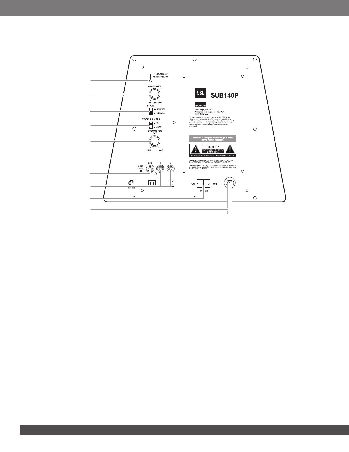
SUBWOOFER REAR-PANEL CONTROLS AND CONNECTIONS
This Class B digital apparatus complies with Canadian ICES-003.
Cet appareil numérique de la classe B est conforme à la norme
NMB-003 du Canada.
On/Standby
LED
Crossover
Control
Phase Switch
Power-On
Mode Switch
Subwoofer
Level Control
Line-Level In
LFE Connector
Line-Level In
L/R Connectors
Power Switch
Power Cord
On/Standby LED:
When the Power-On Mode Switch is in the “Auto” position,
this LED indicates whether the subwoofer is in the On or Standby state:
When the LED • glows green, the subwoofer is turned on.
When the LED • glows red, the subwoofer is in the Standby mode.
When the Power Switch is set to “Off,” the LED will not light up, no matter
what setting the Power-On Mode Switch is in.
Crossover Control:
This control determines the highest frequency at which
the subwoofer reproduces sounds. The higher you set the Crossover Control,
the higher in frequency the subwoofer will operate and the more its bass
will “overlap” that of the satellite speakers. This adjustment helps achieve
a smooth transition of bass frequencies between the subwoofer and the
satellites for a variety of different rooms and subwoofer locations.
NOTE: The Crossover Control functions only when you are using the Line-Level
In L/R Connectors. The Line-Level In LFE Connector bypasses the subwoofer’s
built-in crossover and Crossover Control.
Phase Switch:
This switch determines whether the subwoofer driver’s
piston-like action moves in and out in phase with the satellite speakers. If the
subwoofer were to play out of phase with the satellite speakers, the sound
waves from the satellites could partially cancel out the sound waves from the
subwoofer, reducing bass performance and sonic impact. This phenomenon
depends in part on the placement of all the speakers relative to each other in
the room.
Power-On Mode Switch:
When this switch is set in the “Auto” position and
the Power Switch is set to “On,” the subwoofer will automatically turn itself
on when it receives an audio signal and will enter the Standby mode when it
has gone without receiving an audio signal for 20 minutes. When this switch
is set in the “On” position, the subwoofer will remain on whether or not it is
receiving an audio signal.
Subwoofer Level Control:
Use this control to adjust the subwoofer’s
volume. Turn the knob clockwise to increase the volume; turn the knob
counterclockwise to decrease the volume.
Line-Level In LFE Connector:
This input bypasses the subwoofer’s internal
crossover circuitry, so use it only with a receiver or processor subwoofer
output that has been low-pass filtered. If your receiver or processor does
not have a dedicated subwoofer output that is low-pass filtered, use the
subwoofer’s Line-Level In L/R Connectors (see below) instead.
Use the supplied mono RCA cable (purple connectors) to connect the LineLevel In LFE Connector to the dedicated subwoofer output of a receiver or
preamp/processor.
Line-Level In L/R Connectors:
These inputs pass through the subwoofer’s
built-in crossover. Use them if your receiver or preamp/processor does not
have a dedicated subwoofer output that is low-pass filtered.
Power Switch:
Set this switch in the “On” position to turn the subwoofer on.
The subwoofer will then be in On or Standby mode, depending on the setting
of the Power-On Mode Switch.
Power Cord:
After you have made and verified all subwoofer and speaker
connections described in this manual, plug the power cord into an active,
unswitched electrical outlet for proper operation of the subwoofer. DO NOT
plug this cord into the accessory outlets found on some audio components.
4
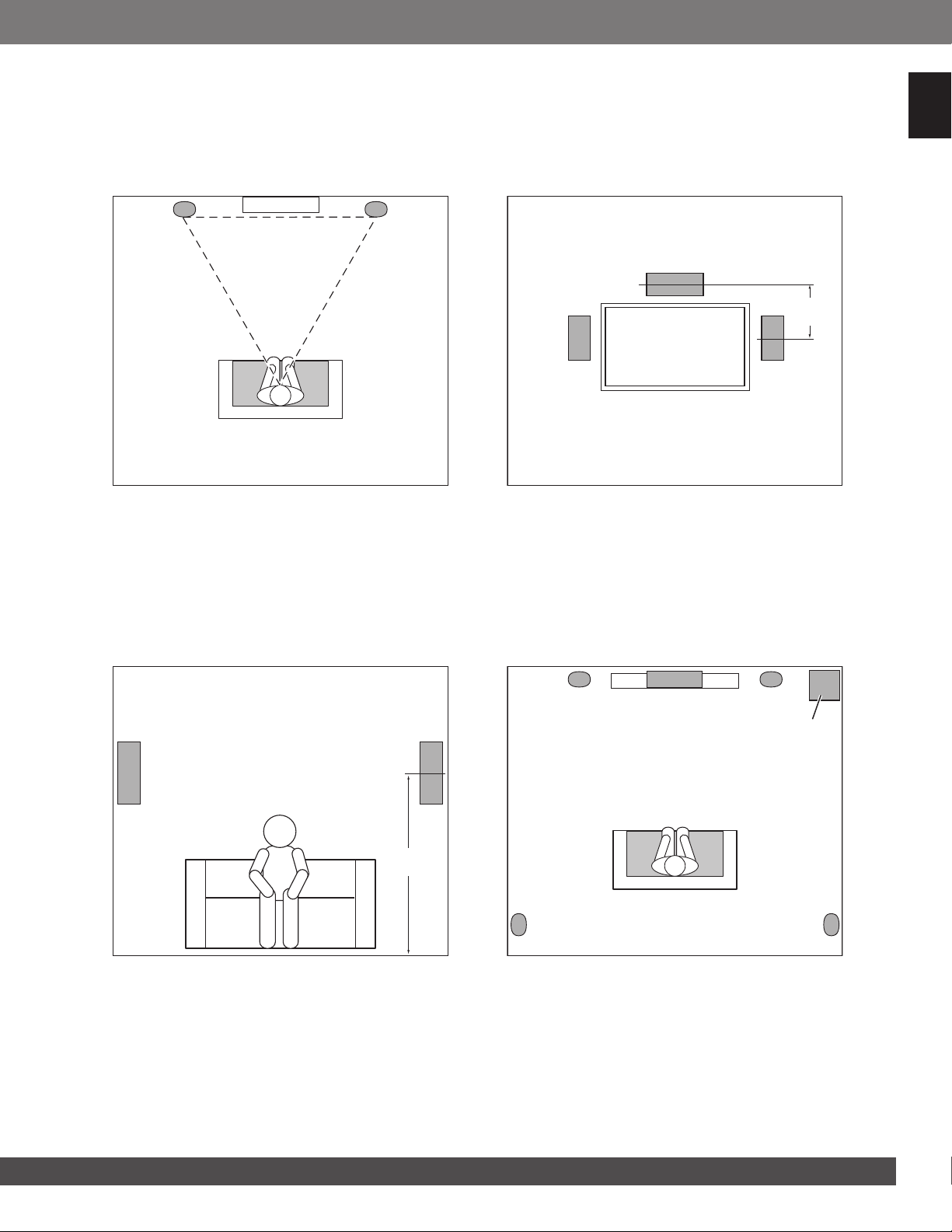
PLACING THE SPEAKERS
FRONT LEFT AND RIGHT SPEAKERS CENTER SPEAKER
ENGLISH
TV
Front Left
Speaker
Surround Right
Speaker
Front Right
Speaker
Front Left
Speaker
SURROUND SPEAKERS AND SUBWOOFER
Front Left
Speaker
Surround Left
Speaker
Center
Speaker
0 – 2 ft
(0 – 61cm)
TV
Front Right
Speaker
TV
Center
Speaker
Front Right
Speaker
Subwoofer
5 – 6 ft
(1.5m – 1.8m)
Surround Left
Speaker
Surround Right
Speaker
www.jbl.com
5
 Loading...