

Page 1

USER’S GUIDE
BRX308-LA
BRX325SP
BRX308-ACC
BRX308-PM
BRX308-AF
Page 2

TABLE OF CONTENTS
SAFETY INFORMATION ................................................................................. 3
Safety Instructions ..................................................................................... 3
General Hardware Information .................................................................. 4
Important Safety Warning ..........................................................................4
INSPECTION & MAINTENANCE .................................................................... 5
Inspection & Maintenance ......................................................................... 5
Attachment To Structures .......................................................................... 5
ORDERING INFORMATION ........................................................................... 6
PRODUCT INFORMATION ............................................................................. 7
BRX300 System ........................................................................................ 7
BRX308-LA Dual 8” 2-Way Line Array Element ........................................ 8
BRX325SP Dual 15” Subwoofer Housing DSP & Amplier Module .......... 8
SYSTEM WIRING INFORMATION ............................................................... 10
SYSTEM APPLICATION GUIDE ................................................................... 11
Option 1 - Ground Stack Option .............................................................. 11
Option 2 - Pole Mount Option .................................................................. 12
ACCESSORIES.............................................................................................13
BRX308-ACC Transporter Kit .................................................................13
BRX308-PM Storage ............................................................................... 14
BRX308-AF Array Frame ........................................................................ 15
SPECIFICATIONS ....................................................................................... 16
System Specications ............................................................................. 16
BRX308-LA Specications ...................................................................... 16
BRX325SP Specications ....................................................................... 16
2
System Frequency Response ................................................................. 17
System Directivity .................................................................................... 17
JBL BRX300 SERIES
Page 3

SAFETY INFORMATION
Before using a JBL BRX Series system, please review the following for important information on safety and
protection of your investment.
SAFETY INSTRUCTIONS
1. Read these instructions.
2. Keep these instructions.
3. Heed all warnings.
4. Follow all instructions.
5. Do not expose the product to direct rain or sea spray.
6. Clean only with a dry cloth.
7. Do not install near any heat sources such as radiators, heat registers, stoves, or other apparatus that produce
heat.
8. Only use attachments / accessories specied by the manufacturer.
9. Use only with a cart, stand, tripod, bracket, or table specied by the manufacturer or sold with the
apparatus. When a cart is used, use caution when moving the cart / apparatus combination to
avoid injury from tip-over.
10. Refer all servicing to qualied service personnel. Servicing is required when the apparatus has been damaged
in any way, such as liquid has been spilled or objects have fallen into the apparatus, the apparatus has been
exposed to rain or moisture, does not operate normally, or has been dropped.
11. Contact JBL Professional for advanced servicing issues.
12. CAUTION – DO NOT PERFORM ANY SERVICING UNLESS YOU ARE QUALIFIED TO DO SO.
13. Prolonged exposure to excessive SPL can cause hearing damage: the loudspeaker is easily capable of
generating sound pressure levels (SPL) sucient to cause permanent hearing damage to performers, production
crew and audience members. Caution should be taken to avoid prolonged exposure to SPL in excess of 90 dB.
14. Read the System Rigging Manual before installation and use of the product.
15. Do not block any ventilation openings. Install in accordance with the manufacturer’s instructions.
16. Do not defeat the safety purpose of the polarized or grounding-type plug. A polarized plug has two blades
with one wider than the other. A grounding-type plug has two blades and a third grounding prong. The wide
blade or the third prong are provided for your safety. If the provided plug does not t into your outlet, consult an
electrician for replacement of the obsolete outlet.
17. Protect the power cord from being walked on or pinched, particularly at plugs, convenience receptacles, and
the point where they exit from the apparatus.
18. Unplug this apparatus during lightning storms or when unused for long periods of time.
19. To completely disconnect this apparatus from the AC mains, disconnect the power supply cord plug from the
AC receptacle.
20. “WARNING – TO REDUCE THE RISK OF FIRE OR ELECTRIC SHOCK, DO NOT EXPOSE THIS APPARATUS
TO RAIN OR MOISTURE.”
21. Do not expose this equipment to dripping or splashing and ensure that no objects lled with liquids such as
vases, are placed on the equipment.
22. The main plug of the power supply cord shall remain readily operable.
USER’S GUIDE
3
Page 4

SAFETY INFORMATION
GENERAL HARDWARE INFORMATION
Any hardware used in an overhead suspension application must be load rated for the intended use. Generally,
this type of hardware is available from rigging supply houses, industrial supply catalogs and specialized rigging
distributors. Local hardware stores do not usually stock these products. Hardware that is intended for overhead
suspension will comply with ASME B30.20 and will be manufactured under product traceability controls. Compliant
hardware will be referenced with a working load limit (WLL) and a traceability code.
IMPORTANT SAFETY WARNING
The information in this section has been assembled from recognized engineering data and is intended for
informational purposes only. None of the information in this section should be used without rst obtaining competent
advice with respect to applicability to a given circumstance. None of the information presented herein is intended as
a representation or warranty on the part of JBL. Anyone making use of this information assumes all liability arising
from such use.
All information presented herein is based upon materials and practices common to North America and may not
directly apply to other countries because of diering material dimensions, specications and/or local regulations.
Users in other countries should consult with appropriate engineering and regulatory authorities for specic
guidelines.
Correct use of all included hardware is required for secure system suspension. Careful calculations should always
be performed to ensure that all components are used within their working load limits before the array is suspended.
Never exceed the maximum recommended load ratings.
THIS APPARATUS CONTAINS POTENTIALLY LETHAL VOLTAGES. TO PREVENT ELECTRIC SHOCK OR
HAZARD, DO NOT REMOVE CHASSIS, INPUT MODULE OR AC INPUT COVERS. NO USER SERVICEABLE
PARTS INSIDE. REFER SERVICING TO QUALIFIED SERVICE PERSONNEL.
The lighting ash with arrowhead symbol within an equilateral triangle is intended to alert the user
to the presence of uninsulated “Dangerous Voltage” within the product’s enclosure that may be of
sucient magnitude to constitute risk of electric shock to persons.
The exclamation point within an equilateral triangle is intended to alert the user to the presence
of important operating and maintenance (servicing) information in the literature accompanying the
product.
4
JBL BRX300 SERIES
Page 5

INSPECTION & MAINTENANCE
INSPECTION & MAINTENANCE
Before suspending any speaker system always inspect all components (enclosure, rigging frames, pins, eyebolts,
track ttings, etc.) for cracks, deformations, corrosion or missing/loose/damaged parts that could reduce strength
and safety of the array. Do not suspend the speaker until the proper corrective action has been taken. Use only
load-rated hardware when suspending JBL suspendable loudspeaker models.
Suspension systems are comprised of mechanical devices and, as such, they require regular inspection and routine
maintenance to ensure proper functionality. Before suspending or pole mounting any speaker system, always
inspect all components (enclosure, suspension frames or brackets, pins, eyebolts, etc.) for cracks, deformations,
corrosion or missing/loose/damaged parts that could reduce strength and safety of the array.
Do not suspend or pole mount the speaker until the proper corrective action has been taken.
Installed systems should be inspected at least annually. The inspection shall include a visual survey of all corners and
load-bearing surfaces for signs of cracking, water damage, delamination or any other condition that may decrease
the strength of the loudspeaker enclosure.
Accessory suspension hardware provided with or for BRX systems must be inspected for fatigue at least annually
or as required by local ordinance. The inspection shall include a visual survey of the material for signs of corrosion,
bending or any other condition that may decrease the strength of the fastener. Additionally, any eyebolts shall be
checked for possible spin-out of the enclosure.
For all other hardware and ttings, refer to the hardware manufacturer’s inspection and maintenance guidelines for
process.
JBL is not responsible for the application of its products for any purpose or the misuse of this information for any
purpose. Furthermore, JBL is not responsible for the abuse of its products caused by avoiding compliance with
inspection and maintenance procedures or any other abuse.
Prior to suspending the system, an expert, trained and experienced in suspending speaker systems, should inspect
all parts and components.
ATTACHMENT TO STRUCTURES
A licensed Professional Engineer must approve the placement and method of attachment to the structure prior to
the installation of any overhead object. The following performance standards should be provided to the Professional
Engineer for design purposes: Uniform Building Code as applicable, Municipal Building Code as applicable and
Seismic Code as applicable. The installation of the hardware and method of attachment must be carried out in the
manner specied by the Professional Engineer. Improper installation may result in damage, injury or death.
USER’S GUIDE
5
Page 6
ORDERING INFORMATION
MODEL NUMBER DESCRIPTION
BRX308-LA Dual 8” line array element
BRX325SP Dual 15” subwoofer with power amplier and DSP for entire system
BRX308-ACC Accessory Kit – Transport cart for 4 x BRX308-LA, soft cover for cart, soft cover for subwoofer, speaker
cables for system
BRX308-AF Array frame for suspending up to 8 x BRX308-LA
BRX308-PM Pole mount + adapter kit
6
JBL BRX300 SERIES
Page 7

PRODUCT INFORMATION
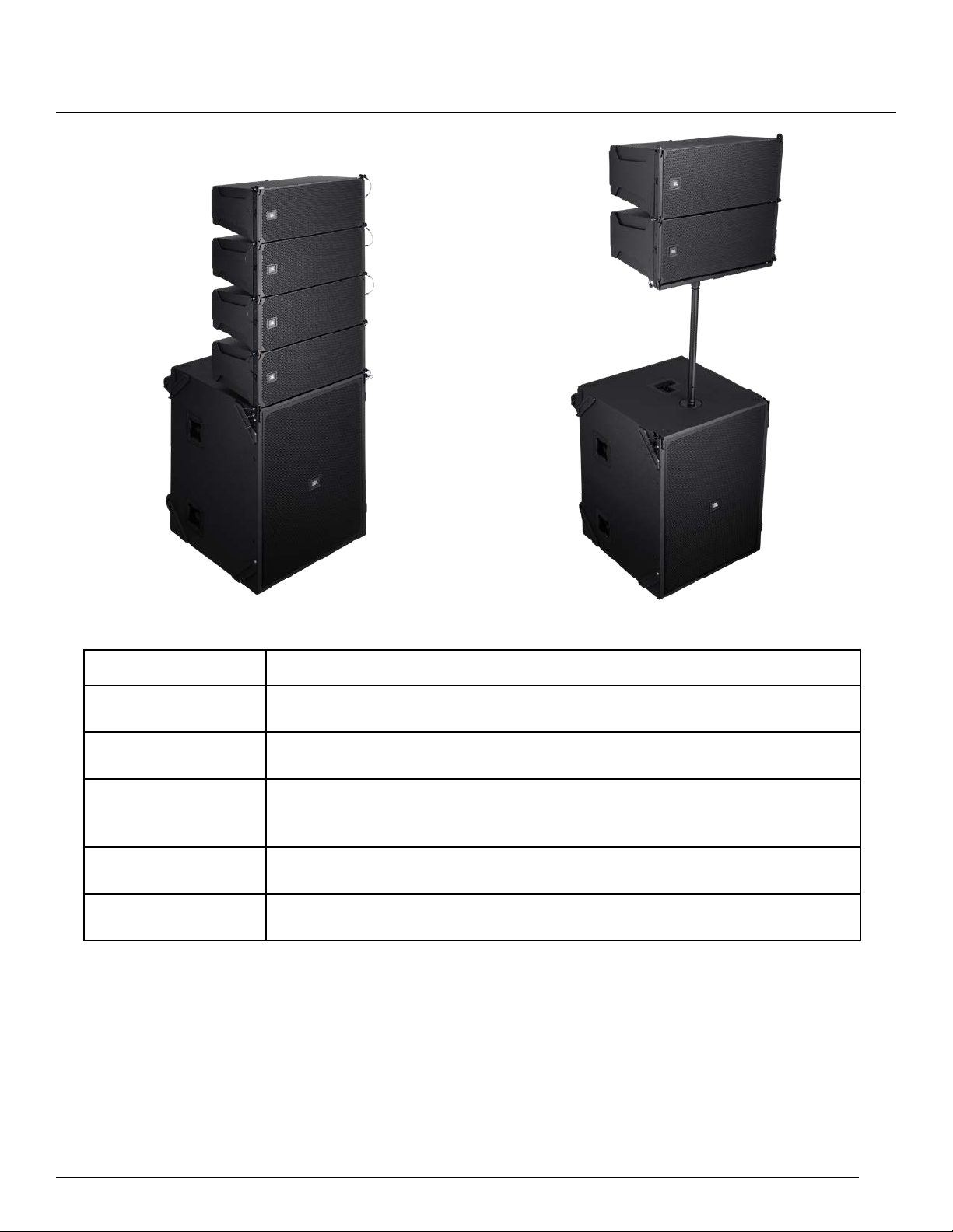
BRX300 SYSTEM
The BRX300 System is a true plug and play solution that features a combination of the BRX308-LA Dual 8” 2-Way
Line Array Element and the BRX325SP Dual 15” Subwoofer that also houses a 6-channel high-power amplier
along with a 48kHz/24-bit DSP for loudspeaker tuning. All the components are packaged to maximize use of space,
ease of handling and setup.
The power and processing module features BSS Audio processing for the subwoofer and 2 circuits of 2 x BRX308LA, each including linear phase FIR lters and dbx limiter suite for loudspeaker protection. As such, no external
processing is required.
This system is primarily intended for ground stack use (4 x BRX308-LA + 1 x BRX325SP) and pole stacked ( 2 x
BRX308-LA + 1 x BRX325SP with the pole and adapter sold with the BRX308-PM Pole Mount Kit).
There is a third option of use as a own system (up to 8 x BRX308-LA suspended from 1 x BRX308-AF). The
subwoofers remain stacked on the ground. Each Subwoofer can power up to 4 x BRX308-LA using the built-in
power module.
SIGNAL
LIMIT
CLIP
NORMAL
FAULT
TOP IN TOP A
TOP OUT
SUB IN
SUB OUT
INPUT Y
SIGNAL
LIMIT
CLIP
NORMAL
DSP + AMPLIFIER
NORMAL
FAULT
TOP B
FAULT
SUB
USER’S GUIDE
7
Page 8

PRODUCT INFORMATION
BRX308-LA Dual 8” 2-Way Line Array Element
The BRX308-LA combines 2 x 8” woofers with a single 3” high
frequency compression driver mounted to a purpose-built planar
waveguide that is derived from JBL Professional’s deep technology
expertise and experience with loudspeaker design.
The BRX308-LA has a simple yet highly ecient
rigging system that allows a lot of options to optimize
audience coverage whether used in ground stacked,
pole mounted or own conguration. Available inter-
enclosure angles are 0, 1, 2, 3, 4, 5, 6, 8, 10 and 12°.
Each BRX308-LA has 2 x Neutrik NL4 connectors
wired in parallel and can be used as system input or
as a pass through connection for daisy-chaining up to
2 cabinets in parallel for amplication with the power
module built in the BRX325SP subwoofer system.
8
BRX325SP Dual 15” Subwoofer Housing DSP & Amplier
Module
The BRX325SP uses 2 x 15” subwoofer transducers with ports
designed to extend low frequency response and increase eciency of
the system.
The BRX325SP ships with 4 heavy-duty castors installed on its back
that enables ease of transport while also protecting the amplier module
connectors and switches.
The BRX325SP has a rigging system that allows up to 4 x BRX308-LA
to be mounted onto it for ground stacked applications.
Additionally, a pole mount cup allows for up to 2 x BRX308-LA to be
pole mounted onto the subwoofer using components from the optional
BRX308-PM System.
The subwoofer also houses the DSP and amplier module that powers
the entire system.
JBL BRX300 SERIES
Page 9

PRODUCT INFORMATION
The module has a Neutrik 20A PowerCon power supply input connector for its power supply and ships with a
power cord specic to the region it is purchased in. A power switch allows the module to be powered ON or OFF.
The module has 2 XLR-F input connectors: one for the subwoofer and one for the BRX308-LA tops. These
connectors are wired in parallel to XLR-M connectors to enable daisy-chaining of input signal to other systems.
There is a switch that allows for the subwoofer and tops to share the same input (INPUT Y) or use the subwoofer on
a separate signal feed (DUAL).
The module also has 2 Neutrik NL4 output connectors (labelled TOP A and Top B) for powering 2 x BRX308-LA on
each output circuit.
The processing and power module has 7 multi-color LED Indicators used to provide feedback on power, input signal
status and amplier status.
Upon powering ON the unit, all the LED’s are lit red while the ampliers and
DSP boot up. Once the DSP and amplier are ready to pass audio, the
LED’s turn green.
The bottom-most LED—marked “POWER”—is lit green when the unit is
receiving power and is in the ON state.
The left 3 LEDS show the amplier status for each of the 3 pairs of amplier
channels that drive the SUB, TOP A and TOP B. When the LED’s are lit
green, the amplier is in the ready state and will pass audio through to the
loudspeakers.
The LED’s light red to indicate a fault with the amplier. Possible reasons
could be thermal shutdown and extended period of output limiting.
The LEDS on the right are used to indicate the status of input signal to each
of the 3 pairs of amplier channels that drive the SUB, TOP A and TOP B.
Green indicates signal presence (>=-40dBu), yellow indicates the onset of
input limiting (+17dBu) while red indicates clipping (>=21dBu) of the input
signal.
It is advised to set up the gain structure so that the yellow status lights only
come on momentarily during maximum drive level from the mixer. Extended
periods of limiting and clipping of the input signal will lead to failure of the
loudspeaker components.
USER’S GUIDE
9
Page 10

SYSTEM WIRING INFORMATION
The below image shows the connection diagram for the BRX308-LA tops from the amplier and DSP module.
Each output on the power amplier module can drive up to 2 x BRX308-LA tops.
The system can be driven in one of two modes:
1. INPUT Y MODE: In this mode, a single output from the mixer feeds the entire system to drive both the sub +
tops.
2. DUAL MODE: In this mode, both the sub and tops can be driven from dierent outputs of the mixer to enable
additional control over the sub + top balance of the system.
From MixerFrom Mixer
From Mixer Aux Out
2. Dual Mode1. Input Y Mode
10
JBL BRX300 SERIES
Page 11

OPTION 1 - GROUND STACK OPTION
SYSTEM APPLICATION GUIDE
The most common use case for the BRX300 system is the ground stack option, as shown above.
It is advised to use an inter-box angle of at least 2° between each BRX308-LA to allow for wide enough vertical
coverage of the high frequencies.
The BRX308-LA has captive rigging hardware that
allows for inter-box angles of 0, 1, 2, 3, 4, 5, 6, 8, 10
and 12°.
To set the inter-box angle to any of the values
mentioned above, align the bottom box’s angle bar
‘Lock’ hole to match with the desired angle value on
the top box and lock it in place with the Quick Release
Pin (Figure 1: Angle Bar 0° shows an example angle
bar setting of 0°).
When setting inter-box angles of 8° and above, the
angle bar of the upper box may obstruct the angle
bar from the below box from aligning with the desired
value. In such cases, the angle bar of the upper
box must be stored using the Quick Release Pin in
the ‘Standby’ hole (as seen in Figure 2: Angle Bar
Standby).
Figure 1: Angle Bar 0° Figure 2: Angle Bar Standby
USER’S GUIDE
11
Page 12

SYSTEM APPLICATION GUIDE
OPTION 2 - POLE MOUNT OPTION
The other option to set up the system is the pole mount option.
A maximum of 2 x BRX308-LA may be mounted on the Pole + Adapter
Kit that is available for purchase as part of the BRX308-PM Pole Mount
Kit.
It is advised to use an inter-box angle of at least 2° between each
BRX308-LA to allow for wide enough vertical coverage of the high
frequencies.
Adapter Bar
The pole mount adapter bar allows for the following angles for the rst box mounted on
it: 0, -2, -3, -4, -5, -6, -8, -9, -10, -11 and -12°. The negative angles allow the rst box
to aim downwards and cover audience that is closer to the array.
To set the rst box at the desired -ve angle value, align the desired value on the adapter
bar to the bottom of the box and lock in place with the Quick Release Pin in the
matching hole.
We recommend an inter-box angle of 10 or 12° for the second speaker. This allows for
more uniform coverage from front to back.
12
JBL BRX300 SERIES
Page 13

ACCESSORIES
BRX308-ACC TRANSPORTER KIT
1. Position transporter cart so there is ample space to move the loudspeakers around. Prepare cart by releasing all
the Quick Release Pins (QRP’s) as shown in Figure 3.
2. It is convenient to assemble the cart for transport using 2 loudspeakers at a time with the inter-box angle
between the speakers pre set to 0° as shown in Figure 3. This same process can be followed even if
assembling the cart one loudspeaker at a time.
3. Seat the loudspeakers on the cart by rst aligning the front and then the rear rigging points of the bottom
loudspeaker to the attachment points on the cart as shown in Figure 4.
4. Insert the QRP’s and lock loudspeakers in place as shown in Figure 5.
5. Follow the same process for the other two loudspeakers on the other side of the cart.
6. Release the QRP’s on the front top rigging points for the upper speakers as seen in Figure 6.
7. Align the Top Lid so the attachment points match with the front top rigging points on the loudspeakers as seen
in Figure 7.
8. Insert the QRP’s and lock the top lid in place as shown in Figure 8.
Figure 3 Figure 4 Figure 5
Figure 6 Figure 8Figure 7
USER’S GUIDE
13
Page 14

ACCESSORIES
BRX308-PM STORAGE
You can store two BRX308-PM kits in the BRX308-ACC top lid for easier pack and transport.
1. Flip the top lid upside down so the at surface is on the oor.
2. Slide the poles in the sleeves as shown in Figure 9, with the threaded portion of the pole going in rst.
3. Release the two front QRP’s on the pole adapter frame and slide into place as shown in Figure 10.
4. Insert the QRP’s through the clamps to lock the adapter in place as shown in Figure 11. The adapter holds the
poles in place and prevents them from sliding out during transport.
Figure 9 Figure 11Figure 10
14
JBL BRX300 SERIES
Page 15

ACCESSORIES
BRX308-AF ARRAY FRAME
The BRX308-AF Array Frame supports a own conguration of one BRX325SP Subwoofer or eight BRX308-LA Line
Array tops.
The Array Frame accepts shackles with a pin diameter of 17/32” and opening width of 1” for attachment to hoists or
other lifting equipment.
To attach the BRX308-AF to an array of BRX308-LA follow the steps below:
1. Place the Array Frame on the topmost BRX308-LA so the frame aligns with the attachment points and secure in
place using the QRP’s on the front of the loudspeaker as shown in Figure 13.
2. Flip up the Angle Bar of the loudspeaker and use the QRP to secure the Angle Bar to the Array Frame by
pinning through the ‘LOCK’ hole on the Angle Bar as shown in Figure 14. This ensures a 0° sight angle for the
rst loudspeaker in the array.
3. To attach the array frame to a BRX325SP Subwoofer, place the Array Frame on the subwoofer so the frame
aligns with the attachment points and secure in place using the QRP’s on the front of the loudspeaker as shown
in Figure 15.
4. Flip up the Angle bar of the subwoofer and use the QRP to secure the Angle bar to the Array frame by pinning
through the ‘LOCK’ hole on the Angle bar as shown in Figure 16.
Figure 12: BRX308-AF
USER’S GUIDE
Figure 13
Figure 15 Figure 16
Figure 14
15
Page 16

SPECIFICATIONS
SYSTEM SPECIFICATIONS
The BRX300 Series is a system that ships as dierent SKU’s to enable ease of transportation. The models are meant
to be used together. The specications below are for the systems.
Frequency Range (-10 dB) 32 Hz–20 kHz
Frequency Response (-3 dB) 40 Hz–19 kHz
Max Rated SPL SUB: 136 dB, TOP: 136 dB
System Components SUB: 2 x 15”, TOP (each): 2 x 8” LF + 1 x 3” titanium compression driver
Nominal Coverage (H x V) 110° x 12° each element (vertical coverage is a function of inter-box angles)
System Input Connectors AMP MODULE: 2 x balanced XLR-F wired in parallel to XLR-M for THRU outputs
TOP: 2 x 4-pole NL4 connectors wired in parallel for IN/THRU use
System Output Connectors AMP MODULE: 2 x 4-pole NL4 connectors for powering up to 4 x TOPS
System Power Input 1 x 20A PowerCon, system input voltage is 230 VAC only
Dimensions (H x W x D) TOP: 299 x 662 x 376 mm
SUB: 890 x 690 x 693 mm
Weight TOP: 20.5 kg each
SUB: 86 kg
BRX308-LA SPECIFICATIONS
The BRX300 Series is a system that ships as dierent SKU’s to enable ease of transportation. The models are meant
to be used together. The specications below are for shipping purpose only.
Frequency Range (-10 dB) 80 Hz–20 kHz
Frequency Response (-3 dB) 100 Hz–19 kHz
Max Rated SPL 136 dB
System Components 2 x 8” LF + 1 x 3” titanium compression driver
Nominal Coverage (H x V) 110° x 12° each element (vertical coverage is a function of inter-box angles)
System Input Connectors 2 x 4 pole NL4 connectors wired in parallel for IN/THRU use
Dimensions (H x W x D) 299 x 662 x 376 mm
Weight 20.5 kg each
BRX325SP SPECIFICATIONS
The BRX300 Series is a system that ships as dierent SKU’s to enable ease of transportation. The models are meant
to be used together. The specications below are for shipping purpose only.
Frequency Range (-10 dB) 32 Hz–250 Hz
Frequency Response (-3 dB) 40 Hz–150 Hz
Max Rated SPL 136 dB (calculated based on sensitivity and power ratings)
System Components 2 x 15”
System Input Connectors AMP MODULE: 2 x balanced XLR-F wired in parallel to XLR-M for THRU outputs
System Output Connectors AMP MODULE: 2 x 4-pole NL4 connectors for powering up to 4 x TOPS
System Power Input 1 x 20A PowerCon, system input voltage is 230 VAC only
Dimensions (H x W x D) 890 x 690 x 693 mm
Weight 86 kg
16
JBL BRX300 SERIES
Page 17

SYSTEM FREQUENCY RESPONSE
SPECIFICATIONS
* Measured in a 2pi eld.
SYSTEM DIRECTIVITY
* BRX308-LA - Measured in a 4pi eld using system DSP and amplier module.
USER’S GUIDE
17
Page 18

BRX300 SERIES
USER’S GUIDE
Website URLs
China: https://jblpro.com/zh/products/brx300
Asia: https://jblpro.com/en-asia/products/brx300
Issued: 06/20208500 Balboa Boulevard Northridge, CA 91329 USA
 Loading...