

Page 1

QUICK START GUIDE
Page 2
IMPORTANT SAFETY INSTRUCTIONS
CAUTION
1. Read these instructions.
2. Keep these instructions.
3. Heed all warnings.
4. Follow all instructions.
5. Do not use this apparatus near water.
6. Clean only with a dry cloth.
7. Do not block any ventilation openings. Install in
accordance with the manufacturer’s instructions.
8. Do not install near any heat sources such as radiators,
heat registers, stoves, or other apparatus (including
ampliers) that produce heat.
9. Do not defeat the safety purpose of the polarized or
grounding-type plug. A polarized plug has two blades
with one wider than the other. A grounding-type plug
has two blades and a third grounding prong. The wide
blade or the third prong is provided for your safety. If
the provided plug does not t into your outlet, consult
an electrician for replacement of the obsolete outlet.
10. Protect the power cord from being walked on or
pinched, particularly at plugs, convenience receptacles,
and the point where they exit from the apparatus.
11. Only use attachments/accessories specied by the
manufacturer.
12. Use only with a cart, stand, tripod, bracket, or table
specied by the manufacturer, or sold with the
apparatus. When a cart is used, use caution when
moving the cart/apparatus combination to avoid injury
from tip-over.
13. Unplug this apparatus during lightning storms or when
unused for long periods of time.
14. Refer all servicing to qualied service personnel.
Servicing is required when the apparatus has been
damaged in any way, such as power-supply cord or
plug is damaged, liquid has been spilled or objects
have fallen into the apparatus, the apparatus has been
exposed to rain or moisture, does not operate normally,
or has been dropped.
15. Use the mains plug to disconnect the apparatus from
the mains.
16. WARNING: TO REDUCE THE RISK OF FIRE
OR ELECTRIC SHOCK, DO NOT EXPOSE THIS
APPARATUS TO RAIN OR MOISTURE.
17. DO NOT EXPOSE THIS EQUIPMENT TO DRIPPING OR
SPLASHING AND ENSURE THAT NO OBJECTS FILLED
WITH LIQUIDS, SUCH AS VASES, ARE PLACED ON
THE EQUIPMENT.
18. THE MAINS PLUG OF THE POWER SUPPLY CORD
SHALL REMAIN READILY OPERABLE.
The BRX300 Series amplier is only
RISK OF ELECTRIC SHOCK
DO NOT OPEN
TO PREVENT ELECTRIC SHOCK DO NOT REMOVE TOP
OR BOTTOM COVERS OF THE AMPLIFIER. NO USER
SERVICEABLE PARTS INSIDE. REFER SERVICING TO
QUALIFIED SERVICE PERSONNEL.
WATCH FOR THESE SYMBOLS:
The lightning bolt triangle is used to alert the user to the risk of
electric shock.
The exclamation point triangle is used to alert the user to
important operating or maintenance instructions.
MAGNETIC FIELD
CAUTION! Do not locate sensitive high-gain equipment
such as preampliers directly above or below the unit.
Because this amplier has a high power density, it has
a strong magnetic eld which can induce hum into
unshielded devices that are located nearby. The eld is
strongest just above the unit.
certied for 230V operation.
WELCOME
Thank you for purchasing a BRX300 Series system. This system is designed to be a true plug-andplay high-output loudspeaker system solution that features a combination of the BRX308-LA dual
8” 2-way line array element and the BRX325SP dual 15” subwoofer that also houses a 6-channel
high-power amplier along with 48kHz/24-bit DSP for loudspeaker tuning. All the components are
packaged to maximize use of space, ease of handling and setup.
For additional product information, please download the owner’s manual at http://jblpro.com.
Trademark Notice: JBL, Crown, dbx and BSS are Trademarks of HARMAN International.
ORDERING INFORMATION
MODEL DESCRIPTION
BRX308-LA Dual 8” line array element
BRX325SP
BRX308-ACC Accessory kit: Transport cart for 4 x BRX308-LA, soft cover for cart, soft cover for subwoofer,
BRX308-AF Array frame for suspending up to 8 x BRX308-LA
BRX308-PM Pole mount + adapter kit
Dual 15” subwoofer with power amplier and system DSP
speaker cables for system
2 JBL BRX300 SERIES
Page 3
1
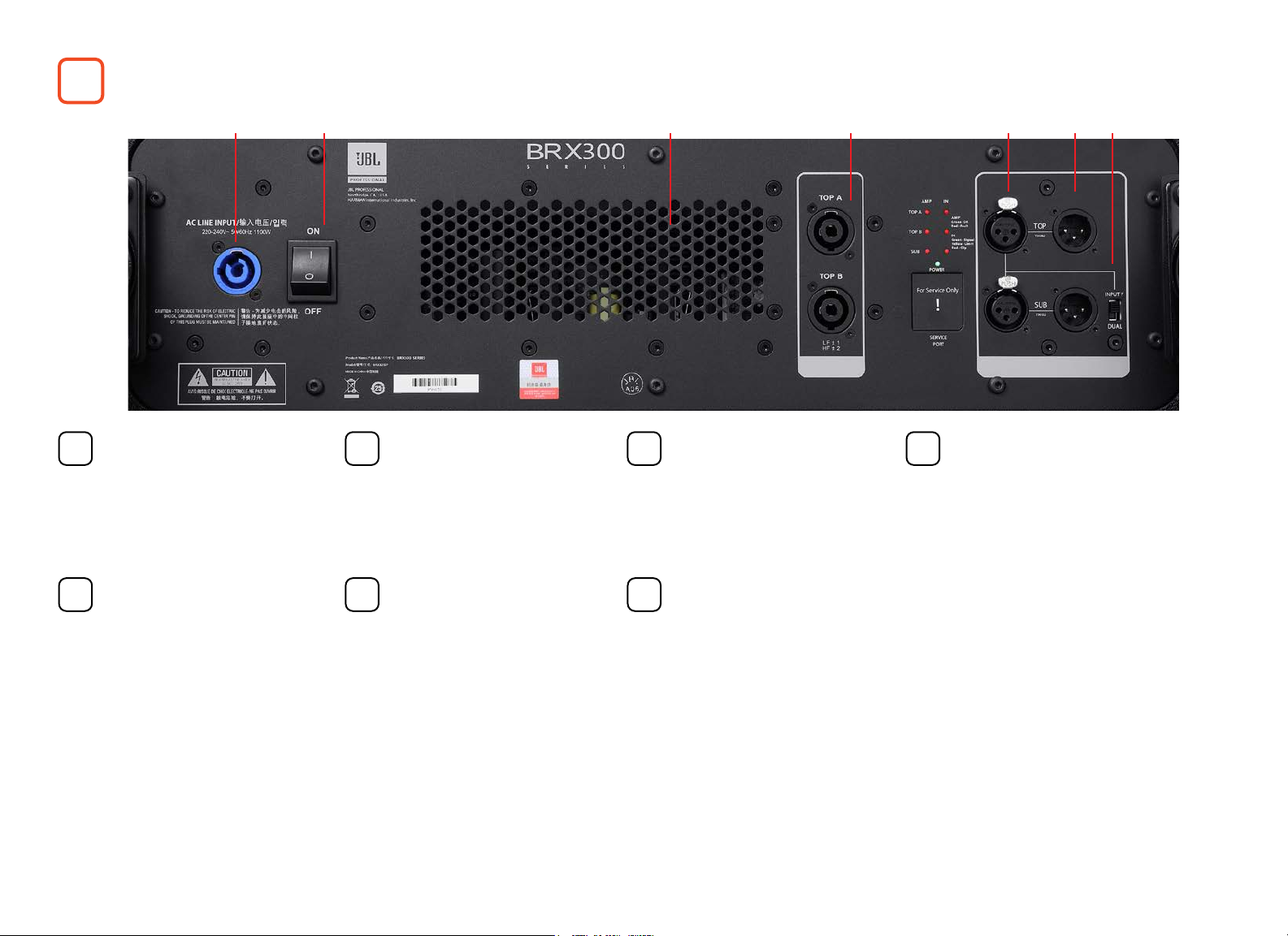
AMPLIFIER PANEL OVERVIEW
1 2 3 4 5 6 7
POWER SUPPLY INPUT
1
This PowerCon connector
provides the mains power
supply to the unit.
AUDIO INPUTS
5
There are two audio inputs
on balanced XLR connectors
labelled TOP and SUB. These
provide the audio input signal
to the TOP amplier and SUB
amplier respectively.
POWER BUTTON
2 3 4
Turns the amplier power on
or o.
AUDIO THRU OUTPUTS
6 7
There are two audio THRU
outputs on balanced
XLR connectors that are
connected in parallel to the
audio inputs. These outputs
are unprocessed and are
not buered. They may be
used to daisy-chain multiple
amplier units.
COOLING VENTS
The vents provide air Flow to
cool the amplier. DO NOT
BLOCK these vents.
MODE SWITCH
This switch toggles the
amplier between ‘INPUT Y’
and ‘DUAL’ input modes.
In ‘INPUT Y’ mode, the
ampliers receive their Input
ONLY from the connector
labelled ‘TOP’. This signal
drives both the SUB and TOP
outputs.
In ‘DUAL’ mode, a separate
signal is required at the input
labelled ‘SUB’ to drive the
subwoofer (SUB output).
AMPLIFIER OUTPUTS
FOR TOPS
There are two 4-pole outputs
for the tops labelled TOP A
and TOP B. Each output may
be used to power up to 2 x
BRX308-LA speakers.
3QUICK START GUIDE
Page 4

2
BRX308-LA OVERVIEW
Fig. 2: Speaker Connectors
IN/THRU SPEAKER CONNECTORS
1
There are two 4-pole speaker connectors
on each BRX308-LA loudspeaker. See
Figure 2. These are connected in parallel
and either connector may be used as
INPUT or THRU to daisy-chain to another
loudspeaker. Up to two BRX308-LA
speakers may be connected in parallel to
one amplier output.
1
Fig. 3: BRX308-LA Angle Bar View
The BRX308-LA has captive rigging hardware that allows for inter-box angles of 0,
1, 2, 3, 4, 5, 6, 8, 10 and 12°.
To set the inter-box angle to one of the values mentioned above, align the bottom
box’s angle bar ‘Lock’ hole to match with the desired angle value on the top box
and lock it in place with the Quick Release Pin.
4 JBL BRX300 SERIES
Page 5

3
AMPLIFIER SETUP
CONNECTING THE AC POWER CORD
Connect your amplier to the AC mains power outlet using the supplied AC power cord. First, connect the PowerCon end of the cord to the PowerCon
connector on the amplier. Then plug the other end of the cord to the AC mains.
WARNING: The third (ground) prong of the supplied AC power cord connector is a required safety feature. Do not attempt to disable this ground
connection by using an adapter or other methods.
Make certain the AC mains voltage and current ratings are sucient to deliver full power to the speaker system. The BRX300 Series amplier is made to
operate at 230 VAC, 50 Hz ONLY.
POWER-UP PROCEDURE
1. Connect the tops to the amplier using 4-core cable wired to the NL4 connectors. Up to two tops may be wired in parallel to each output of the
amplier (labelled ‘TOP A’ and ‘TOP B’). Connect the input source to the XLR inputs and select the appropriate drive mode (‘Dual’ or ‘INPUT Y’).
2. Toggle the amplier’s POWER button to the ON position. The POWER indicator will light green and the amplier will boot as long as sucient mains
power is provided. During boot-up, all the other status LEDs are red. The LEDs turn o to indicate the amplier is ready. If Input signal is present, the
Input LED’s will light green.
3. Turn your audio source up to an optimum level. The BRX300 Series amplier will begin to limit input signals at +17 dBu, and the inputs begin clipping
at +21 dBu. To prevent damage to the system, it is recommended that you do NOT run the system in the limit or clip state for long periods.
The bottommost LED, labelled POWER, is lit green when the unit is receiving power and is in the ON state.
The left three LEDs show the amplier status for each of the three pairs of amplier channels that drive the SUB, TOP A and TOP
B. When the LEDs are lit green, the amplier is in the ‘ready’ state and will pass audio through to the loudspeakers. If these LEDs
light red, it indicates a fault with the amplier. Possible reasons could be thermal shutdown or extended period of output limiting.
The LEDs on the right are used to indicate the status of input signal to each of the three pairs of amplier channels that drive the
SUB, TOP A and TOP B. Green indicates signal presence (≥-40 dBu), yellow indicates the onset of Input limiting (≥17 dBu), while
red indicates clipping (≥21 dBu) of the input signal.
It is advised to set up the gain structure so that the yellow status LEDs only light momentarily during maximum drive level from
the mixer. Extended periods of limiting and clipping of the input signal will lead to failure of the loudspeaker components.
5QUICK START GUIDE
Page 6

4
SYSTEM SETUP EXAMPLES
The most common use case for the BRX308 system is the ground stack option, as shown in Figure 4.
It is advised to use an inter-box angle of at least 2° between each BRX308-LA to allow for wide enough vertical coverage of the
high frequencies.
When ground-stacking on the subwoofer, the built-in anchor point on the subwoofer (Figure 5) allows for +ve angle values (tops
pointing upwards). To set +ve angles for the 1st top on the sub, align the ‘Lock’ hole on the sub anchor point to the desired angle
on the top and secure in place with the Quick Release Pin.
To set the inter-box angles, align the bottom box’s angle bar ‘Lock’ hole to match the desired angle value on the top box and lock
it in place with the Quick Release Pin.
When setting inter-box angles of 8° and above, the angle bar of the upper box may obstruct the angle bar from the box below
from aligning with the desired value. In such cases, the angle bar of the upper box must be stored using the Quick Release Pin in
the ‘Standby’ hole.
Fig. 4: Ground Stack Option
1
Fig. 5: BRX325SP Top View
6 JBL BRX300 SERIES
Page 7

The other option is to set up the system using the pole mount option, as shown in Figure 6.
A maximum of 2 x BRX308-LA speakers may be mounted on the pole adapter kit that is available for purchase as part of the
BRX308-PM Kit.
It is advised to use an inter-box angle of at least 2° between each BRX308-LA to allow for wide enough vertical coverage of the high
frequencies.
The pole mount adapter bar allows for the following angles for the rst mounted box: 0, -2, -3, -4, -5, -6, -8, -9, -10, -11 and -12°.
The negative angles allow the rst box to aim downwards and cover audience members that are closer to the array.
To set the rst box at the desired -ve angle value, align the desired value on the adapter bar (see Figure 7) to the bottom of the box
and lock it in place with the Quick Release Pin in the matching hole.
We recommend an inter-box angle of 10° or 12° for the second box. This allows for more uniform coverage from front to back.
The system sub/top balance in this pole mount conguration will have more sub energy (when compared to the ground stack option
using 1 sub + 4 tops). We recommend reducing the sub volume from the mixer if required.
Fig. 6: Pole Mount Option
Fig. 7: Adapter Bar
7QUICK START GUIDE
Page 8

Website URLs
China: https://jblpro.com/zh/products/brx300
Asia: https://jblpro.com/en-asia/products/brx300
BRX300 SERIES
QUICK START GUIDE
Issued: 6/2020
 Loading...