

Page 1

BPX1100.1
2 CHANNEL
POWER AMPLIFIER
SERVICE MANUAL
JBL CONSUMER PRODUCTS
250 CROSSWAYS PARK DRIVE, WOODBURY, NY 11797
8500 BALBOA BOULEVARD, NORTHRIDGE, CA91329
WWW.JBL.COM
Page 2

Power Amplifier
BPX1100.1
Controls and connections
Specifications ..........................................................1
Features ..................................................................2
Test Conditions and Notes .........................................2
Controls and Connections ..........................................3
Mounting the amplifier................................................3
Typical System Configuration (Wiring) .........................4
Printed Circuit Boards (Top View)................................5~7
Parts Lists..............................................................8~11
Block Diagrams......................................................12
Packaging Exploded View........................................13
Integrated Circuit Diagrams......................................14~16
Transistor Diagrams................................................17~18
Schematic Diagrams...............................................19~21
Amplifier Exploded View...........................................22
SPECIFICATIONS
Power Output,4 Ohoms . . . . . . . . . . . . . . . . . . .
Power Output,2 Ohoms . . . . . . . . . . . . . . . . . . .
Power Output,Bridged, 4 Ohoms . . . . . . . . . . . . . . .
Power Output,Parallel, 1 Ohoms . . . . . . . . . . . . . . .
MIN.Speaker Impedance . . . . . . . . . . . . . . . . . .
Frequency Response . . . . . . . . . . . . . . . . . . .
N/A
575W x 2
1100W x 1
1100W x1
1 ohm
20Hz ~ 320KHz,-3dB
Input Sensitivity (RCA type) . . . . . . . . . . . . . . ..
THD + Noise (4 Ohms) . . . . . . . . . . . . . . . . . . .
Signal-to-Noise . . . . . . . . . . . . . . . . . . . .
Maximum Current Draw. . . . . . . . . . . . . . . . . . . .
Fuse Replacement. . . . . . . . . . . . . . . . . . . . . .
250mV~6V
0.5%
93dB
110A
30A x 3
External Dimensions (Inches)
Length . . . . . . . . . . . . . . . . . . . . . . . . . . .
Width . . . . . . . . . . . . . . . . . . . . . . . . . . .
Depth . . . . . . . . . . . . . . . . . . . . . . . . . . .
12-1/4
17
2-9/16
External Dimensions (mms)
Length . . . . . . . . . . . . . . . . . . . . . . . . . . .
Width . . . . . . . . . . . . . . . . . . . . . . . . . . .
Depth . . . . . . . . . . . . . . . . . . . . . . . . . . .
312
432
66
JBL continually strives to improve its products. New materials, production methods and design refinements are
introduced into existing models without notice as a routine expression of our design philosophy. For this reason,
BP Series Multichannel Automotive Amplifiers may differ in some respects from their published specifications
and descriptions, but will always equal or exceed the original specifications unless otherwise stated.
1
Page 3

Power Amplifier
Features
2-Channel Operation
Advanced MOSFET Oversized Floating Rail Power Supply
Floating Ground Factory - Head - Unit Speaker - Level input
Variable Input Sensitivity (250mV - 6V)
Fully Complementary Output Stage with Class-D Voltage Amplification
Gold-plated Power, Input and Output Connectors
1-Ohm Stable ( 2 ohm parallel )
BPX1100.1
Test Conditions and Notes
All tests to be done, unless otherwise specified, from 20Hz to 320Hz at 14.4V DC into 2 ohm loads and adjust
the units gain so that with a .775 volt input signal the unit is at its maximum rated output. All measurements
will be done using an Audio precision system one and the supply voltage.
An A+ line voltage of 14.4V DC shall be applied to the unit under test for all measurements unless otherwise
specified. The voltage applied to the unit shall be measured at the power connection on the Amplifier.
Signal Source
Unless otherwise specified, all tests shall be conducted with the Audio Signal Generator output configured to
be balanced, less than or equal to 50 ohm source impedance, and floating. The signal source "GND" shall be
connected to the Amplifier PWR GND at the Amplifier.
Output Load
Unless otherwise specified, all tests shall be conducted with 2 ohm resistive loads having less than 10%
reactive components at any frequency below 350Hz. Each resistor shall have a value that remains within 1%
while dissipating the rated output of the unit under test.
Power Indicator LED steadily illuminates for normal operation. LED blinks when
protection circuitry is engaged, and during power up.
2
Page 4

Power Amplifier
BPX1100.1
Controls and Connections
1 2 3
1011
9
8
Controls and Connections
1. Power Connection for 12V+, GND and REM
connections for power wires. See wiring instruc tions on page 4 for more information.
2. Fuse - Three 30 Amp ATC type Fuses.
3. Speaker Output Connector - Connect speaker
wiring to these connectors. See wiring instruc tions on page 4 for more information.
4. Preamp-Level Input Connector - Connects to
line-level output from the source unit.
5. Pre amp-Level AUX output Connector
6. Input-Level Control - Adjusts input sensitivity
for pre-amp level and speaker level inputs.
Mounting the Amplifier
7
7. This switch is select X-over slope
8. This switch is set to 2-channel mode(2CH/BR) to drive
a pair of subwoofers or bridge(mono) mode to drive a
single subwoofer(PARALLEL).
It's allowed to use parallel mode when the nominal
impedance of the speaker system is 2 ohm or greater
9.
Remotr Volume Control Jack.
10. The crossover frequency can be set at any frequency
Between 32Hz and 320Hz.
11. (1) The HP frequency can be set at any frequency
Between 20Hz and 100Hz.
(2) Bass Boost control will provide at frequency
Being set between 20Hz ~ 100Hz
4 56
The JBL BP Series amplifiers can be mounted in virtually any location inside the vehicle.
However, make sure to keep the amplifier away from heater vents or ducts.
1. At the chosen site, use the amplifier as a mounting template and mark the locations of the
four mounting holes.
2. Drill a small pilot hole at each marked location.
3. Mount the amplifier and securely tighten the mounting screws.
3
Page 5

Power Amplifier
Power
Antenna
Antenna Input
Cassette/Receiver
Power Supply
Wires
Typical System Configuration
Cassette/CD Tuner
(Head Unit)
BPX1100.1
CD Player or Changer
Power
Antenna
Relay
Power Supply
Antenna Motor Ground
Remote Antenna
Fuse
Remote On/Off
Ignition
Switch
Red - Main +12V
Black - Power Ground
Line
Level
Input
Fuse
Black Power
Remote On/Off
60 Amp (Not Included)
Fuse
Power Ground
Main +12V
Amplifier
Power
Connection
Vehicle Battery
Chassis Ground
Speakers
4
Page 6
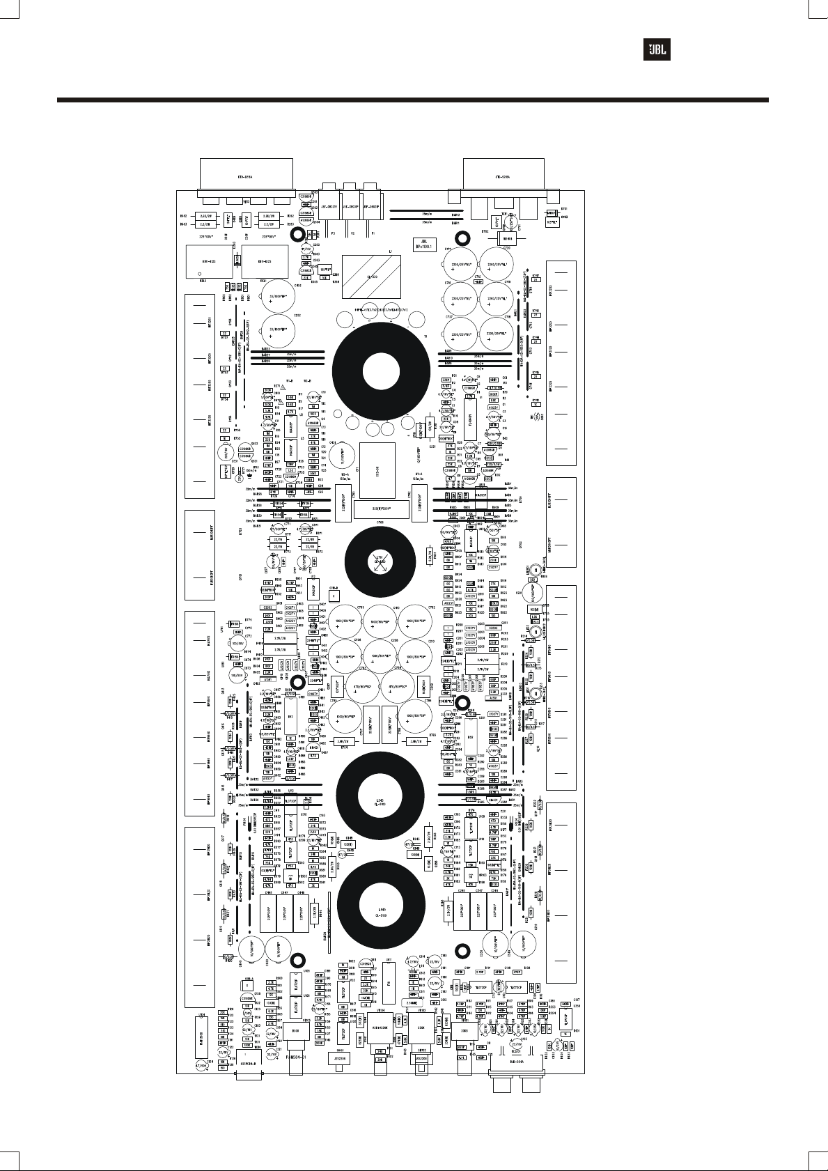
Power Amplifier
BPX1100.1
Printed Circuit Board (Top View)
5
Page 7

Power Amplifier
BPX1100.1
Printed Circuit Board (BOTTOM View)
6
Page 8

Power Amplifier
BPX1100.1
Printed Circuit Board (SUB TOP View)
PAS132-01
REV.0
VR701
2K
R701
A20K
VR701
2K
R701
A20K
REV.0
PAS132-01
PAS132-01
REV.0
VR701
VR701
2K
R701
MOD02 MOD02
623PCB4-B 623PCB4-B
623PCB4-B 623PCB4-B
MOD02 MOD02
2K
R701
A20K
REV.0
PAS132-01
PAS132-01
REV.0
VR701
VR701
2K
R701
623PCB4-B
A20K A20K
MOD02
2K
R701
A20K
REV.0
PAS132-01
PAS132-01
REV.0
VR701
VR701
2K
R701
MOD02 MOD02
623PCB4-B 623PCB4-B
623PCB4-B
A20K
MOD02
2K
R701
A20K
REV.0
PAS132-01
PAS132-01
REV.0
VR701
VR701
2K
R701
MOD02
623PCB4-B
623PCB4-B
A20K
MOD02
2K
R701
A20K
REV.0
PAS132-01
7
Page 9

Power Amplifier
BPX1100.1
BPX1100.1 Parts List
PART NO.
PCB-00-00952
TRS-00-00088
TRS-00-00087
TRS-00-00110
TRS-00-00090
DIO-00-00108
DIO-00-00003
DIO-00-00006
DIO-00-00041
RES-00-00401
RES-00-00463
RES-00-00499
RES-00-00586
RES-00-00590
RES-00-00393
RES-00-00443
RES-00-00450
RES-00-00489
RES-00-00523
RES-00-00541
RES-00-00561
RES-00-00581
RES-00-00588
RES-00-00402
RES-00-00415
RES-00-00436
RES-00-00456
RES-00-00480
RES-00-00508
RES-00-00537
RES-00-00550
RES-00-00565
RES-00-00591
RES-00-00405
RES-00-00498
RES-00-00636
RES-00-00705
RES-00-00660
RES-00-00606
RES-00-00622
RES-00-00656
RES-00-00662
RES-00-00712
RES-00-00723
RES-00-00728
RES-00-00633
RES-00-00598
RES-00-00602
RES-00-00637
RES-00-00644
RES-00-00699
RES-00-00672
RES-00-00700
RES-00-00702
RES-00-00720
RES-00-00608
RES-00-00616
RES-00-00623
RES-00-00630
RES-00-00658
RES-00-00663
RES-00-00666
RES-00-00680
RES-00-00697
RES-00-00714
RES-00-00748
RES-00-00604
RES-00-00620
RES-00-00647
RES-00-00654
RES-00-00635
RES-00-00600
RES-00-00053
RES-00-00018
RES-00-00040
RES-00-00038
RES-00-00808
RES-00-00800
IND-00-00020
CEC-00-00007
6
NOMENCATURE
IC
TRANSISTOR
TRANSISTOR
TRANSISTOR
TRANSISTOR
DIODE
DIODE
DIODE
DIODE
RESISTOR
RESISTOR
RESISTOR
RESISTOR
RESISTOR
RESISTOR
RESISTOR
RESISTOR
RESISTOR
RESISTOR
RESISTOR
RESISTOR
RESISTOR
RESISTOR
RESISTOR
RESISTOR
RESISTOR
RESISTOR
RESISTOR
RESISTOR
RESISTOR
RESISTOR
RESISTOR
RESISTOR
RESISTOR
RESISTOR
RESISTOR
RESISTOR
RESISTOR
RESISTOR
RESISTOR
RESISTOR
RESISTOR
RESISTOR
RESISTOR
RESISTOR
RESISTOR
RESISTOR
RESISTOR
RESISTOR
RESISTOR
RESISTOR
RESISTOR
RESISTOR
RESISTOR
RESISTOR
RESISTOR
RESISTOR
RESISTOR
RESISTOR
RESISTOR
RESISTOR
RESISTOR
RESISTOR
RESISTOR
RESISTOR
RESISTOR
RESISTOR
RESISTOR
RESISTOR
RESISTOR
RESISTOR
RESISTOR
RESISTOR
RESISTOR
RESISTOR
RESISTOR
RESISTOR
RESISTOR
INDUCTOR
CAPACITOR
DESCRIPTION
SHUNT REGULATOR
SMALL SIGNAL NPN
SMALL SIGNAL PNP
SMALL SIGNAL NPN
SMALL SIGNAL PNP
FEST RECOVERY
RECTIFIER
SWITCHING SIGNAL
ZENER O.5W 12V
METAL FILM 1/5WF
METAL FILM 1/5WF
METAL FILM 1/5WF
METAL FILM 1/5WF
METAL FILM 1/5WF
METAL FILM 1/5WF
METAL FILM 1/5WF
METAL FILM 1/5WF
METAL FILM 1/5WF
METAL FILM 1/5WF
METAL FILM 1/5WF
METAL FILM 1/5WF
METAL FILM 1/5WF
METAL FILM 1/5WF
METAL FILM 1/5WF
METAL FILM 1/5WF
METAL FILM 1/5WF
METAL FILM 1/5WF
METAL FILM 1/5WF
METAL FILM 1/5WF
METAL FILM 1/5WF
METAL FILM 1/5WF
METAL FILM 1/5WF
METAL FILM 1/5WF
METAL FILM 1/5WF
METAL FILM 1/5WF
CARBON FILM 1/5WJ
CARBON FILM 1/5WJ
CARBON FILM 1/5WJ
CARBON FILM 1/5WJ
CARBON FILM 1/5WJ
CARBON FILM 1/5WJ
CARBON FILM 1/5WJ
CARBON FILM 1/5WJ
CARBON FILM 1/5WJ
CARBON FILM 1/5WJ
CARBON FILM 1/5WJ
CARBON FILM 1/5WJ
CARBON FILM 1/5WJ
CARBON FILM 1/5WJ
CARBON FILM 1/5WJ
CARBON FILM 1/5WJ
CARBON FILM 1/5WJ
CARBON FILM 1/5WJ
CARBON FILM 1/5WJ
CARBON FILM 1/5WJ
CARBON FILM 1/5WJ
CARBON FILM 1/5WJ
CARBON FILM 1/5WJ
CARBON FILM 1/5WJ
CARBON FILM 1/5WJ
CARBON FILM 1/5WJ
CARBON FILM 1/5WJ
CARBON FILM 1/5WJ
CARBON FILM 1/5WJ
CARBON FILM 1/5WJ
CARBON FILM 1/5WJ
CARBON FILM 1/5WJ
CARBON FILM 1/5WJ
CARBON FILM 1/5WJ
CARBON FILM 1/5WJ
CARBON FILM 1/5WJ
CARBON FILM 1/5WJ
METAL FILM 0.5WJ
METAL FILM 0.5WJ
METAL FILM 0.5WJ
METAL FILM 0.5WJ
METAL FILM 1WJ
METAL FILM 1WJ
COIL AXIAL 5%
CERAMIC TUBULAR 50V
MFR PARTS
KIA431/KIA431A
KTC1027Y
KTA1023Y
KTC3198GR
KTA1266GR
FR154
1N4004
1SS133
1N5242
100 OHM
220 OHM
300 OHM
820 OHM
910 OHM
1.5K OHM
2.2K OHM
2.7K OHM
3.3K OHM
4.7K OHM
5.1K OHM
6.8K OHM
8.2K OHM
9.1K OHM
10K OHM
12K OHM
18K OHM
20K OHM
27K OHM
33K OHM
47K OHM
51K OHM
62K OHM
91K OHM
110K OHM
300K OHM
1 OHM
4.7 OHM
22 OHM
100 OHM
150 OHM
220 OHM
240 OHM
470 OHM
510 OHM
560 OHM
1K OHM
1.5K OHM
1.8K OHM
2.2K OHM
2.7K OHM
3K OHM
3.3K OHM
4.3K OHM
4.7K OHM
5.6K OHM
10K OHM
12K OHM
15K OHM
18K OHM
22K OHM
24K OHM
27K OHM
30K OHM
39K OHM
47K OHM
75K OHM
100K OHM
150K OHM
200K OHM
220K OHM
1M OHM
1.5M OHM
4.7 OHM
10 OHM
22 OHM
220 OHM
22 OHM
2.2K OHM
100uH
10pF
REF. NO
U282,482
Q203,205,207,209,281,403,405,407,409,481
Q914
Q1,204,206,208,210,282,404,406,408,410
Q482,916,920
Q2,6,128,362,363,365,611,631,632,705
Q3,4,8,9,364
D771,772,774,871,872,874
D363,701
D01,02,181,281,282,283,284,481,482,483
D484,581,725,801,802,909,913,914,915,922
D923,924,925
D201,202,401,402,901
R204,404
R203,403
R906,952
R116
R202,206,402,406
R288,488
R113,557
R117
R554
R111,112,114,177,179,555,556,577,579
R2
R807
R905,951
R805
R150,353,354,453,454,591
R806
R118
R26
R27
R01
R103,104,105,106,107,108,109,110,904,950
R23
R808
R101,102
R22
R30
R207,208,211,212,407,408,411,412
R8
R619,743,744,745,747,753,754,755,757
R115,282,482,915,922,924,925
R130
R21,603
R151
R174,233,433,574
R123,125
R809
R33,183,185,290,351,451,490,583,585,613
R622,742,752
R723,725
R3,153
R6,155,173,201,205,281,401,405,481,573
R4,157,363
R181,581
R10,600,614
R141,142,156
R17,34,145,154,180,188,189,287,487,571
R588,589,590,601,726,916
R9,11,143,144
R25,121,124,126,127,132,283,286,289,362
R364,483,486,489,569,570,617,618,724,907
R908,910,911,913,918,920,921,923,953
R602
R7,122,129
R917
R14,16,19,31,32,187,365,587,615
R184,584
R28,172,572,919
R128
R152
R18,182,186,582,586
R160,176,178,560,576,578,801,802
R13,224,225,226,227,229,230,231,352,425
R426,427,428,429,430,431,452
R131
R149,271,471
R914
R12,15,20,24,361,612,616,621,912
R909
R5
R214,215,216,217,220,221,222,415,416,417
R418,420,421,422
R284,285,484,485
R41,42
R771,772,871,872
R901
L611
C105,106
Q'TY
11
13
10
23
10
13
10
16
29
17
14
2
5
6
2
5
2
2
2
1
4
2
2
1
1
9
1
1
2
1
6
1
1
1
1
1
1
1
2
1
1
8
1
9
7
1
2
1
4
2
1
2
2
3
2
3
3
4
1
3
1
9
2
4
1
1
5
8
1
3
1
9
1
1
4
2
4
1
1
2
8
Page 10

Power Amplifier
BPX1100.1
BPX1100.1 Parts List
PART NO.
CEC-00-00038
CEC-00-00017
CEC-00-00028
CEC-00-00035
CEC-00-00004
CEC-00-00005
CEC-00-00037
CEC-00-00006
MYC-00-00046
MYC-00-00199
MYC-00-00084
MYC-00-00083
MYC-00-00156
MYC-00-00085
MYC-00-00088
MYC-00-00061
MYC-00-00066
MYC-00-00184
MYC-00-00177
MYC-00-00034
MYC-00-00045
ELC-00-00571
ELC-00-00333
ELC-00-00114
ELC-00-00334
ELC-00-00117
ELC-00-00293
ELC-00-00111
ELC-00-00113
ELC-00-00153
ELC-00-00160
ELC-00-00137
ELC-00-00127
ELC-00-00130
ELC-00-00162
ELC-00-00132
ELC-00-00254
REL-00-00009
ICO-00-00017
ICO-00-00055
ICO-00-00003
ICO-00-00022
ICO-00-00170
ICO-00-00095
ICO-00-00157
ICO-00-00162
FET-00-00001
FET-00-00021
FET-00-00037
TRS-00-00112
TRS-00-00096
DIO-00-00102
DIO-00-00048
DIO-00-00198
DIO-00-00277
REN-00-00001
VOL-00-00282
VOL-00-00114
VOL-00-00283
VOL-00-00055
VOL-00-00134
RES-00-01112
RES-00-01018
RES-00-01046
RES-00-01079
RES-00-01099
RES-00-00919
RES-00-00916
RES-00-00947
THS-00-00013
MYC-00-00152
MYC-00-00076
MYC-00-00109
ELC-00-00357
NOMENCATURE
CAPACITOR
CAPACITOR
CAPACITOR
CAPACITOR
CAPACITOR
CAPACITOR
CAPACITOR
CAPACITOR
CAPACITOR
CAPACITOR
CAPACITOR
CAPACITOR
CAPACITOR
CAPACITOR
CAPACITOR
CAPACITOR
CAPACITOR
CAPACITOR
CAPACITOR
CAPACITOR
CAPACITOR
CAPACITOR
CAPACITOR
CAPACITOR
CAPACITOR
CAPACITOR
CAPACITOR
CAPACITOR
CAPACITOR
CAPACITOR
CAPACITOR
CAPACITOR
CAPACITOR
CAPACITOR
CAPACITOR
CAPACITOR
CAPACITOR
RELAY
I.C
I.C
I.C
I.C
I.C
I.C
I.C
I.C
FET
FET
FET
TRANSISTOR
TRANSISTOR
DIODE
DIODE
LED
LED
RESONATOR
VOLUME
VOLUME
VOLUME
VOLUME
SEMI VOLUME
RESISTOR
RESISTOR
RESISTOR
RESISTOR
RESISTOR
RESISTOR
RESISTOR
RESISTOR
THERMISTOR
CAPACITOR
CAPACITOR
CAPACITOR
CAPACITOR
DESCRIPTION
CERAMIC TUBULAR 50V
CERAMIC TUBULAR 50V
CERAMIC TUBULAR 50V
CERAMIC TUBULAR 50V
CERAMIC TUBULAR 50V
CERAMIC TUBULAR 50V
CERAMIC TUBULAR 50V
CERAMIC TUBULAR 50V
MYLAR 5% 63V "BOX"
MYLAR 5% 400V "BOX"
MYLAR 5% 63V "TL"
MYLAR 5% 63V "TL"
MYLAR 5% 63V "TL"
MYLAR 5% 63V "TL"
MYLAR 5% 63V "TL"
MYLAR 5% 63V "TL"
MYLAR 5% 63V "TL"
MYLAR 5% 100V
MYLAR 5% 100V
MYLAR 5% 50V
MYLAR 5% 50V
ELECTROLYTIC "NE"
ELECTROLYTIC "NP"
ELECTROLYTIC "SRE,SE"
ELECTROLYTIC "SRE,SE"
ELECTROLYTIC "SRE,SE"
ELECTROLYTIC "SRE,SE"
ELECTROLYTIC "SRE,SE"
ELECTROLYTIC "SRE,SE"
ELECTROLYTIC "SMS/SHL/SG"
ELECTROLYTIC "SMS/SHL/SG"
ELECTROLYTIC "SMS/SHL/SG"
ELECTROLYTIC "SMS/SHL/SG"
ELECTROLYTIC "SMS/SHL/SG"
ELECTROLYTIC "SMS/SHL/SG"
ELECTROLYTIC "SMS/SHL/SG"
ELECTROLYTIC "SXE"
DC12V,10A
PRECISION COMPARATOR(DIP-14)
14-STAGE COUNTER(DIP-16)
DUAL OP AMP
PWM
VOLUME IC
VOLTAGE REGULATOR
VOLTAGE REGULATOR
N-CH MOSFET
P-CH MOSFET
N-CH MOSFET
VIDEO NPN
VIDEO PNP
FAST RECOVERY
RECTIFIER
3PHI BLUE
3PHI RED
2.56MHz
V12L5(9x5)G(4R)(PH2D)N15KC-A2Kx2+A200Kx2
V12L5(9x5)G)PH2D)N17KC-3B20Kx2
V12L5(9x5)G)PH2D)N17KC-B500x2
V12L5(9X5)G(PH2D)N15KC-15C50Kx4
6PHI , 5KB
MOR 2WJ SMALL TYPE"FORMING 15m/m"
MOR 2WJ SMALL TYPE
MOR 2WJ SMALL TYPE"FORMING 15m/m"
MOR 2WJ SMALL TYPE"FORMING 15m/m"
MOR 2WJ SMALL TYPE"FORMING 15m/m"
MOR 3WJ
MOR 3WJ
SHUNT 5WJ (3P, 10m/m)
NTC RESISTOR 50K
MYLAR 10% 100V "BOX"
MYLAR 10% 100V "BOX"
MYLAR 10% 250V "BOX"
ELECTROLYTIC "BP"(12.5x20)
MFR PARTS
47pF
220pF
330pF
470pF
102pF
103pF
473pF
104pF
102J
102J
103J
104J
184J
105J
224J
334J
474J
102J
103J
333J
823J
22/16V
22/16V
1/50V
2.2/16V
4.7/16V
4.7/50V
22/16V
100/16V
1/50V
4.7/50V
10/25V
22/16V
47/16V
100/50V
220/16V
100/25V
KB11-E12S
B52
F16
TL072CP
TL494CN
NJM13600
KIA393P
KIA7812PI
KIA7912PI
IRF3205
IRF9640
IRFB31N20D
C3503
A1381
MUR3040PT
1N5404
HL304H1BC2
HNRD-3401L
CSA2.56MG
RG06P-5KB
2.2 OHM
47 OHM
100 OHM
2.2K OHM
3.9K OHM
220 OHM
2.7K OHM
0.01 OHM
FTD5-350
105K
225K
225K
10/100V
REF. NO
C611,612,617
C726
C616,618
C111
C5,8,17,905,951
C286,486
C3,187,188,189,190,191,192,193,194,195
C196,197,198
C01,12,13,14,15,94,181,182,201,202
C204,205,211,281,282,285,289,290,291,292
C361,363,401,402,404,405,411,481,482,485
C489,490,491,492,613,714,715,721,722,774
C778,874,878,902
C9,280,480,904,950
C761
C172,572
C265,465
C152
C284,364,484,702,703,723
C203,206,403,406
C143
C151
C119,245,445,725
C255,455,602,615
C144
C141,142
C173,573
C113,156
C801,913
C287,293,487,493
C4,6,7,95,283,288,483,488
C1,2,11,771,871,908
C08,10
C16,777,877,903
C123
C124,614
C353,453
C101,102,103,104,121,122,183,184,185,186
C362
C773,873
C631
C701
REL1,2
U281,481
U611
U101,102,103,105,106,108,109,110,112,350
U509,510
U1
U104
U2,3,12,801,901
U761
U861
Q742,743,744,746,752,753,754,756
Q212,213,214,215,413,414,415,416
Q217,218,219,417,418,419
Q201,401
Q202,402
D761,762,763,764
D702
LED2
LED1,801
X611
VR104
VR101
VR105
VR102
VR103,503
R263,463
R245,445
R761
R246,255,262,446,455,462
R764,765
R727
R209,210,409,410
R234,434
TH1
C207,209
C246,247,248,264,446,447,448,464,762,763
C787,788
C768
C249,250,251,449,450,451
Q'TY
3
1
2
1
5
2
13
44
5
1
2
2
1
6
4
1
1
4
4
1
2
2
2
2
4
8
6
2
4
1
2
2
10
1
2
1
1
2
2
1
12
1
1
5
1
1
8
8
6
2
2
4
1
1
2
1
1
1
1
1
2
2
2
1
6
2
1
4
2
1
2
12
1
6
9
Page 11

Power Amplifier
BPX1100.1
BPX1100.1 Parts List
PART NO.
ELC-00-00009 CAPACITOR 2
ELC-00-00173 CAPACITOR
ELC-00-00282 CAPACITOR
ELC-00-00474 CAPACITOR
ELC-00-00627 CAPACITOR
COR-TF-00366 RING CORE
COI-00-00083 INDUCTOR
COI-00-00104 INDUCTOR
COI-00-00105 INDUCTOR
COI-00-00106 CURRENT SENSOR
TER-00-00219 TERMINAL
TER-00-00220 TERMINAL
HOD-00-00006 FUSE HOLDER
JAC-00-00050 MODULAR JACK
JAC-00-00043 RCA JACK
SWI-00-00056 SWITCH
JUP-00-00003 JUMPER
JUP-00-00029 JUMPER
JUP-00-00028 JUMPER
JUP-00-00013 JUMPER
WIR-00-00184 WIRE
WIR-00-00173 WIRE
WIR-00-00110 WIRE
TUB-00-00008 TEFLON TUBE
FUS-00-00010 AUTO FUSE
NOMENCATURE
DESCRIPTION
ELECTROLYTIC "BP"(16x25)
ELECTROLYTIC "SG"(16x25)
ELECTROLYTIC "SHL/SD"(10x20)
ELECTROLYTIC "SD"(16x31)
ELECTROLYTIC "WL"(16x25)
44PHI,MAGNETICS
120uH
50A
GOLD PLATED
GOLD PLATED
PCB TYPE
4P
GOLD PLATED
SLIDE SWITCH
METAL BAR
62mm 5 LEAD
46mm 4 LEAD
2P
AWG #14 RED
AWG #14 RED
AWG #22 BLACK (3PHI RING LUG)
0.7PHI
ATC
MFR PARTS
33/100V
470/80V
100/100V
1000/80V
2200/25V "WL"
3T(0.7x22):13T(0.7x4)+4T(0.7x1)
CL-4100
CL-5100
CL-330
CCS-50
KTD-9216A
KTD-9218A
JSF08031P
623PCB4-B
DJB-554A
JSS-2208
35m/m
MA-BA-02-1961-0(5P)
MA-BA-02-1962-0(4P)
MA-BA-02-1529-1(2P)
125m/m
135m/m
150m/m
10m/m
30A
REF. NO
C252,452
C783,784
C901
C208,210,408,410,781,782,785,786
C716,717,718,719,720,727
T1
L761
L245,445
L1
CT1
TER2
TER1
F1,2,3
MOD1
RCA101
SW102,103
BAR1,2,3,4,5,6,7,8,9,10
BAR11,12,25,26,27,28,29,30,31,32
BAR33,36
BAR15,19,20,22,23,39
BAR13,14,16,17,21,24
BAR38
W1(W1-A,W1-B)
W2(W2-A,W2-B)
W03
TH1
SET 3 + ACCESSORY 3
Q'TY
22
2
1
8
6
1
1
2
1
1
1
1
3
1
1
2
6
6
1
1
1
1
2
6
VOL-00-00044 VOLUME
RES-00-00668 RESISTOR
JAC-00-00050 MODULAR JACK
JAC-00-00128 MODULAR JACK ASS'Y
V9M5720009A
CARBON FILM 1/5WJ
4P
4P(5 METER)
A20Kx2 (9 PHI)
2K OHM
KEK623PCB4-B
VR701
R701
MOD02
ACEESSORY
1
1
1
1
10
Page 12

Power Amplifier
BPX1100.1
BPX1100.1 Parts List
PART NO.
NOMENCATURE
HEA-01-576AA HEAT SINK MAIN
DESCRIPTION
AL/EXTRUSION(L=430.0mm)
REF. NO
Q'TY
(BLACK SPRAY,SANDTON) 1
PAN-06-562AA PANEL FRONT EGI,1.2t BLACK SPRAY(SANDTON) 1
PAN-06-565AA PANEL REAR EGI,1.2t BLACK SPRAY(SANDTON) 1
COV-22-623B0 WINDOW ACRYLIC,3.0t 1
BAD-01-515AA BADGE AL LOGO:JBL,MODEL NAME: SILK 1 1
FOO-01-504B0 FOOT MOUNTING ADC-7(DIE CASTING) 2
COV-22-549AA LENS ACRYLIC 2
ILL-22-503A0 INDICATOR ACRYLIC(CLEAR) 3
BKT-14-522A0 BRACKET LAMP SK5(BK-P) ACCESSORY 4
BKT-05-519A0 BRACKET TR(A) CR,47.0x15.0x1.5t(NI-P) 2
BKT-05-520A0 BRACKET TR(B) CR,91.0x15.0x1.5t(NI-P) 2
BKT-05-521A0 BRACKET TR(C) CR,103.0x15.0x1.5t(NI-P) 4
SUB-28-572A0 CUSHION BKT-TR(A) FIBER,43.0x15.0x0.5t 2
SUB-28-573A0 CUSHION BKT-TR(B) FIBER,87.0x15.0x0.5t 2
SUB-28-574A0 CUSHION BKT-TR(C) FIBER,99.0x15.0x0.5t 4
SUB-33-513A0 CUSHION RUBBER(A) RUBBER,5.0x7.0x1.6t THERMISTOR(1) 1
SUB-33-006A0 CUSHION RUBBER(B) RUBBER, 012.0x 0 5.0x2.0t SET(4),REMOTE(2) 6
SIL-34-001A0 SILICON PAD (SP1000)22.0x0.3t 780mm
SUP-29-502A0 SUPPORT PCB NYLON,L=4.5mm 6
SUB-27-524A0 SWITCH DECAL FELT,12.0x7.0x0.3t 2
SUB-28-519A0 PAPER SPACER(A) FIBER,200.0x8.0x0.5t TR 1
SUB-28-503A0 PAPER SPACER(B) FIBER,200.0x10.0x0.5t FET 1
SUB-12-576A0 3>‹ TUBE 05.0x40mm INDICATOR 3
SC5-NB-30120 SCREW STT2 BH 3x12 NI-P PCB SUPPORT 6
SC5-BB-30080 SCREW STT2 BH 3x8 BK
SC1-NL-30060 SCREW
SML 3x6 NI(NO SERRATION)
S/PANEL+H/S(10),RCA(1),TERMINAL(3)
H/S+WINDOW(8) 8
14
SC1-NL-40100 SCREW SML 4x10 NI-P H/S+FOOT MOUNTING(10) 10
SC4-BP-40250 SCREW STT1 PH 4x25 BK BRACKET TR (20) 20
SC4-BL-40250 SCREW STT1 LH 4x25 BK ACCESSORY(4) 4
SC4-BB-40200 SCREW STT1 BH 4x20 BK REMOTE 2
POL-31-084A0 POLY BAG(A) VINYL,380.0x580.0x0.1t SET 1
POL-31-007A0 POLY BAG(B) VINYL,160.0x280.0x0.03t MANUAL 1
POL-31-004A0 POLY BAG(C) VINYL,80.0x100.0x0.03t ACCESSORY 1
POL-31-002A0 POLY BAG(E) VINYL,230.0x350.0x0.03t MANUAL 1
INN-42-533A0 SNOW PAD(L),(R) EPS,378.0x150.0x131.0 2
BOX-36-573AA GIFT BOX
SW#1(B Þ )577.0x383.0x136.0
1
BOX-39-575BA CARTON BOX DW#2,592.0x292.0x408.0 1/2
MAN-01-0052A MANUAL 1
SUB-00-001A0 SILICAGEL
3g
1
LAB-SR-0064A SERIAL NO 3 1
SUB-00-002A0 SCOTCH TAPE 20mm SET 5cm
SUB-00-003A0 OPP TAPE 2.3m
LAB-00-0227A STICKER "MADE IN KOREA" 9 1
LAB-QC-0001A STICKER QC LABEL
1
LAB-00-0165A STICKER WINDOW STICKER SET 1
CAR-WA-0032A WARRANTY CARD 1
PLA-08-016A0 PLATE(A) PVC, 040x 020x1.0t L245,445 2
PLA-08-004A0 PLATE(B) PVC, 033 L761 1
SUP-21-006A0 LED GUIDE(A) ABS,L=12mm LED 3
CAR-00-0234A E-1 STICKER ART PAPER 2
LAB-CE-0004A CE STICKER ART PAPER 2
CAR-00-0100A CERTIFICATE SHEET 1
-----REMOTE CONTROL----COV-01-523AA CASE TOP
COV-06-531AA CASE BOTTOM
BTN-21-509A0 KNOB VOLUME
SC5-BP-30060 SCREW
SC5-BF-30060 SCREW
INN-36-512A0 INNER PAD(I-50)
AL/BAR 41.0x21.5x45.8
EGI,1.0t
ABS/BK
STT2 PH 3x6 BK TOP CASE+BOTTOM CASE+PCB 2
STT2 FH 3x6 BK (CUTTING TYPE) TOP CASE+BOTTOM CASE 4
SW# , 166x80
POL-31-003A0 POLY BAG(D) VINYL,120.0x120.0x0.1t
SUB-00-002A0 SCOTCH TAPE
20mm 5cm
BLACK SPRAY(SANDTON)
REMOTE CONTROL
1
1
1
1
1
SUB-21-525A0 LED GUIDE(B) ABS,L=6mm VOLUME KNOB 6>;³ 1
11
Page 13

Power Amplifier
BPX1100.1
Block Diagram
12
Page 14

Power Amplifier
BPX1100.1
Packaging Exploded View
13
Page 15

Power Amplifier
U1 (TL494CN) P.W.M IC
DEAD TIME
CONTROL
BPX1100.1
Integrated Circuit Diagrams
U2,3,12,801,901 (KIA393P)
OUT A
-IN
+IN
V-
V+
OUT B
-IN
+IN
U101,102,103,105,106,108
U109,110,112,350,509,510 (TL072CP)
OUT A
-IN
+IN
VCC
VCC+
OUTB
-IN
+IN
14
Page 16

Power Amplifier
U281,481 ( B52 )
BPX1100.1
Integrated Circuit Diagrams
INPUT1
INPUT2
NC
NC
V+
NC
V-
V+
VCC
1
2
14
STRDBE1
13
NC
3
4
12
11
INPUT1
OUTPUT1
INPUT2
STROBE1*
INPUT1
GND
5
6
7
10
OUTPUT2
9
8
STRDBE2
V-
INPUT2
STROBE2*
U611 (F16)
Q12
1
Q13
2
Q14
3
Q6
4
Q5
5
Q7
6
Q4
7
VSS
VSS
8
8
16
VDD VDD
16
15
14
Q10
Q8
Q9
13
RESET
12
11
10
9
=VSS
=VDD
1
0
0
12 11 10
3
14
2
13
1
12
11
15
10
13
9
14
8
6
7
R
R
R
7
R
5
R
4
R
1
2
3
4
5
6
9
15
Page 17

Power Amplifier
U104 ( NJM13600D )
BPX1100.1
Integrated Circuit Diagrams
AMP BIAS INPUT B
16
1
DIODE BIAS B
15
2
+ INPUT B
14
-
+
+
-
3
+ INPUT
- INPUT B
13
B
A
4
- INPUT
OUTPUT B
12
5
V+
11
V-
BUFFER INPUT B
10
6
7
BUFFER OUTPUT B
9
8
DIODE BIAS A
AMP BIAS INPUT A
OUTPUT A
BUFFER INPUT A
BUFFER OUTPUT A
16
Page 18

Power Amplifier
BPX1100.1
Transistor Diagrams
E
C
B
E
* KTC3198GR *
Q2,6,128,362,363,365
Q611,631,632,705
C
B
* KTA1266GR *
Q3,4,8,9,364
G
S
C
B
G
E
D
S
* IRFB31N20D *
Q217,218,219,417,418
Q419
D
G
* IRF9640 *
Q212,213,214,215
Q413,414,415,416
D
S
1
1
1
1
2
2
2
2
3
3
3
3
1
1
1
1
* MUR3040PT *
* MUR3040PT *
* MUR3040PT *
* MUR3040PT *
D761,762,763,764
D761,762,763,764
D761,762,763,764
D761,762,763,764
2
2
2 3
2 3
E
C
C
B
3
3
E
* 2SC3503 *
Q201,401
B
B
* 2SA1381 *
Q202.402
C
E
17
Page 19

Power Amplifier
BPX1100.1
Transistor Diagrams
E
C
B
D
G
S
*1RF3205*
Q742,743,744,746,752
Q753,754,756
E
C
B
C
B
E
* KTC1027Y *
Q203,205,207,209,281,403
Q405,407,409,481,914
E
C
B
C
B
E
* KTA1023Y *
Q1,204,206,208,210,282,404,406
Q408,410,482,916,920
1
1
1
1
2
2
2
2
3
3
3
3
1
1
1
1
* MUR3040PT *
* MUR3040PT *
* MUR3040PT *
* MUR3040PT *
D761,762,763,764
D761,762,763,764
D761,762,763,764
D761,762,763,764
2
2
2 3
2 3
3
3
18
Page 20

2 Channel Power Amplifier
BPX1100.1
BPX1100.1 Mechanical Exploded View
22
Page 21

2 Channel Power Amplifier
BPX1100.1
Power Amplifier (Sheet 1)
A
B
C
D
E
G
F
16
1
2 3
4
5 6
7 8 9
19
Page 22

A
2 Channel Power Amplifier
BPX1100.1
Power Amplifier (Sheet 2)
B
C
D
E
1
2
3 4 5 6 7 8 9
20
Page 23

2 Channel Power Amplifier
A
BPX1100.1
Power Amplifier (Sheet 3)
B
C
D
E
1
2
3 4 5 6 7 8 9
21
 Loading...