

Page 1
BP150.1
1 CHANNEL
POWER AMPLIFIER
SERVICE MANUAL
JBL Consumer Products
250 Crossways Park Dr.
Woodbury, New York 11797 Rev0 8/2004
Page 2

BP150.1 1 Channel Automotive Amplifier
CONTENTS
Specifications ………………………………………………………. …..........1
Features ........................………………………………………………...........2
Test Conditions and Notes ............................. .....................….................2
Controls and Connections ............................. .....................…...........…...3
Typical System Configuration (Wiring) ............ .....................…...............4
Printed Circuit Boards (Top View).....……... .....................…....................5
Electrical Parts List............................….... .....................……...................6
Mechanical Parts List........................….... .....................……...................8
Block Diagram....................................... .....................…...…....................9
Packaging ..........................………………… .....................…..................10
Integrated Circuit Diagrams........................ .....................…...................11
Transistor Diagrams.................................... .....................…..................13
Exploded View........................... .....................…....................................14
Schematic Diagrams................... …..........................…............………...15
BP150.1 Specifications
Number of Channels . . . . . . . . ……………….. . 1
4 Ohms Stereo. . . . . . . . . . . . ………………. . . 75W
2 Ohms Stereo . . . . . . . . . . . ……………. . ….. 150W
T.H.D. @ 4 Ohms rated Power . . . . .. . . . . . . . . 0.10%
Frequency Response . . . . . . . . . . . . .. . …. . . . 10Hz ~ 320 Hz
Signal to noise Ratio . . . . . . . . . . . . …. . . . . . . >90dB
Maximum Current Draw . ………………….. . . . 14A
Fuse size. . . . . . . . . . . . . . . ………………. . . . 20A x 1
Input Sensitivity. . …….. . . . . . . . . . .………. . . 250mV ~ 4V
Minimum Speaker Impedance…………………..1 ohm
External Dimensions
Length . . . . . . . . . . . . ……………….. . ..8” (203mm)
Width . . . . . . . . . . . . . . . . . . . . . . . . . . . 8 ¾” (222mm)
Depth . . . . . . . . . . . . . . . . . . . . . . . . . . . 2 11/16 (68mm)
JBL continually strives to improve its products. New materials, production methods and design refinements are introduced
into existing models without notice as a routine expression of our design philosophy. For this reason, BP Series
Automotive Amplifiers may differ in some respects from their published specifications and descriptions, but will always
equal or exceed the original specifications unless otherwise stated.
1
Page 3

BP-150.1
1 Channel Automotive Amplifier
Features
1-Channel Operation
Advanced MOSFET Oversized Floating Rail Power Supply
Floating Ground Factory - Head - Unit Speaker - Level input
Variable Input Sensitivity (250mV - 4V)
Fully Complementary Output Stage with Class-D Voltage Amplification
Gold-plated Power, Input and Output Connectors
1-Ohm Stable
Test Conditions and Notes
All tests to be done, unless otherwise specified, from 10Hz to 320Hz at 14.4V DC into 4 ohm loads and adjust
the units gain so that with a .775 volt input signal the unit is at i's maximum rated output. All measurements
will be done using an Audio precision system one and the supply voltage.
An B+ line voltage of 14.4V DC shall be applied to the unit under test for all measurements unless otherwise
specified. The voltage applied to the unit shall be measured at the power connection on the Amplifier.
Signal Source
Unless otherwise specified, all tests shall be conducted with the Audio Signal Generator output configured to
be balanced, less than or equal to 50 ohm source impedance, and floating. The signal source "GND" shall be
connected to the Amplifier PWR GND at the Amplifier.
Output Load
Unless otherwise specified, all tests shall be conducted with 4 ohm resistive loads having less than 10%
reactive components at any frequency below 350KHz. Each resistor shall have a value that remains within 1%
while dissipating the rated output of the unit under test.
Power Indicator Green LED steadily illuminates for normal operation. Illuminates up Red LED blinks when
protection circuitry is engaged, and during power up.
2
Page 4
1 Channel Automotive Amplifier
BP-150.1
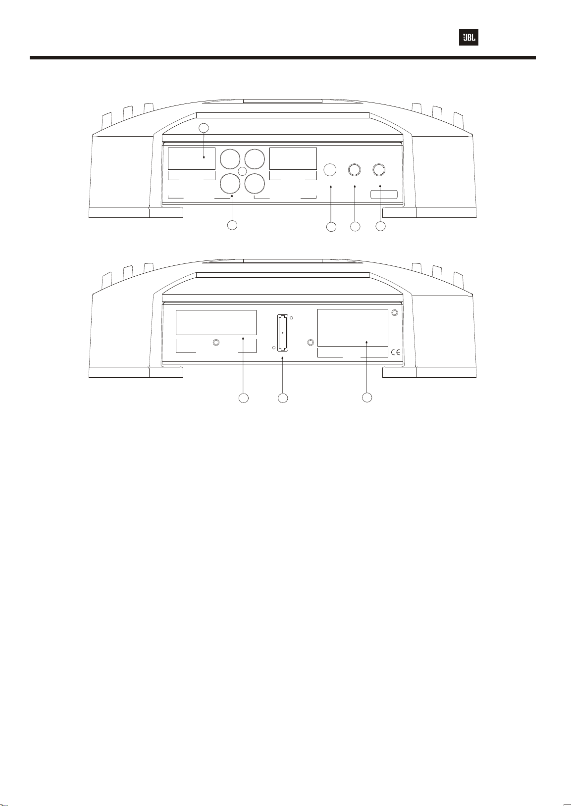
Controls and Connections
8
Controls and Connections
R R
+ R - - L +
HIGH LEVEL
FRONT INPUTS
L L
1
- + - +
SPEAKER OUTPUTS
+ R - - L +
HIGH LEVEL
REAR INPUTS
FUSE 20A
32
INPUT
LEVEL
. .
4V 250mV
+BATT
5
LPF
BASS
FREQ
BOOST
. .
. .
32Hz 320Hz 0dB +6dB
BP150.1
6
REM
GND
POWER
4
7
1. It allows left and right input channels to be
connected to the amplifier using RC plugs.
2. Speaker Output Connector - Connect speaker
4. Power Connection for 12V+, GND and REM
connections for power wires. See wiring instruc tions on page 4 for more information.
5. Input-Level Control - Adjusts input sensitivity
for pre-amp level and speaker level inputs.
wiring to these connectors. See wiring instruc tions on page 4 for more information.
6. The electronic crossover is a 12dB/oct.
Low pass filter which can be Set at any frequency
between 32Hz and 320Hz.
3. Fuse - One 20 Amp ATC type Fuse.
7. The bass boost control will provide up to 6dB of boost
at 50Hz.
8. It allows left and right input channels such as high
level speaker output signal to be the amplifier.
Mounting the Amplifier
The JBL BP Series amplifiers can be mounted in virtually any location inside the vehicle.
However, make sure to keep the amplifier away from heater vents or ducts.
1. At the chosen site, use the amplifier as a mounting template and mark the locations of the
four mounting holes.
2. Drill a small pilot hole at each marked location.
3. Mount the amplifier and securely tighten the mounting screws.
3
Page 5
BP-150.1
Power
Antenna
Antenna Input
Cassette/Receiver
Power Supply
Wires
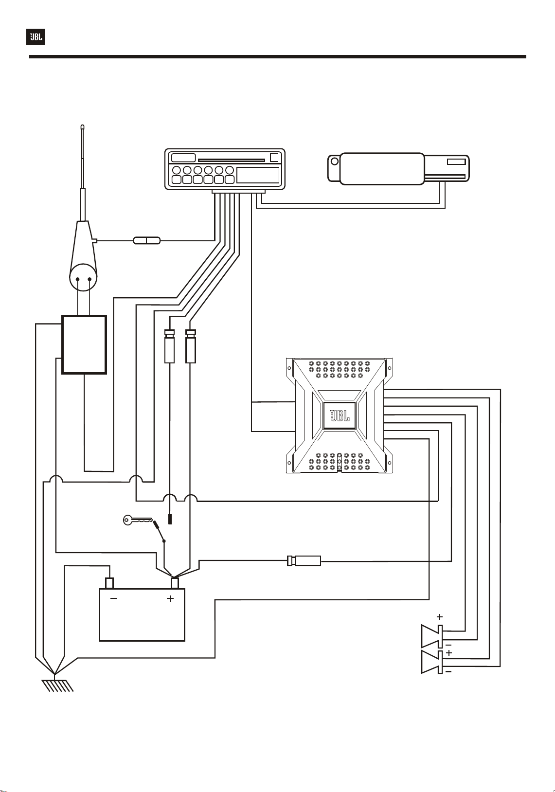
Typical System Configuration
Cassette/CD Tuner
(Head Unit)
1 Channel Automotive Amplifier
CD Player or Changer
Power
Antenna
Relay
Power Supply
Antenna Motor Ground
Remote Antenna
Fuse
Remote On/Off
Ignition
Switch
Red - Main +12V
Black - Power Ground
Line
Level
Input
Fuse
Black Power
Remote On/Off
60 Amp (Not Included)
Fuse
Power Ground
Main +12V
Amplifier
Power
Connection
Vehicle Battery
Speakers
Chassis Ground
4
Page 6
1 Channel Automotive Amplifier
104P
C343
D301
1N4148
D303
R222
10K
47/16V
820K
C3198GR
R277
7
7
CL-700A
1N5404
R304
C303
3.3K
C361
C3198GR
1K/2W
KB11-E12S
IRFZ44
Q342
L301
R301
R316
22/25V
C360
C362
104(M)
D315
1N4148
-
COMMON
+
C341
C321
10/0.5W
4.7K
R306
104(M)
225(M)
KTD-9217
FUSE-RA
Y-FB9402
KTD-9214
R342
R341
22
1K
2
P01
2200/25V"RX"
5
C302
105(M)
C301
100/25"SXE"
1
F01
R307
390K
1N4004
D302
C225
R223
Q222
P2
Q223
C276
22/100V"RN"BP
B
REL01
A
473P
U301
C312
6.8K
105(M)
Q321
104P
Q302
C3198GR
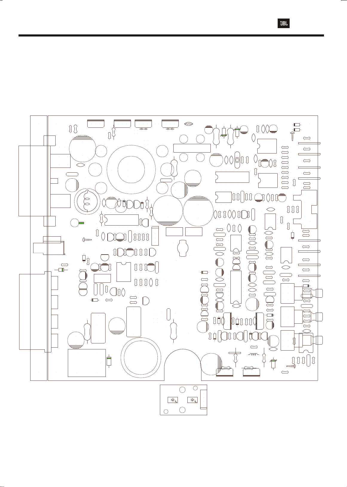
Printed Circuit Board (Top View)
6,75842,31
R351
100/2W
220/50V
C354
C356
R270
47/2W
KLG-124E
PROTECTION
TH01
50K
CL-1110
L351
220/50V
C352
105(M)105(M)
LED01
R344
22
1K
C306
100/16V
A1266GR
2.7K
C331
R333
100K
4.7/50V
10K
R360
Q221
R340
33K
C275
22/100V"RN"BP
D221
PR1504
25M02N
D352
T01
R345
IRFZ44
Q345
29PHI6T(0.7x6):15T(0.7x3)
R318
Q313
Q314
R319
220/0.5W
A1268GR
A1268GR
4.7/50V
47
A1023Y
R323
R303
A1277Y
C271
C305
473P
TL494CN
100K
C323
Q301
KIA393P
33K
R224
104P
D311
1N4148
R320
1.8K
R302
U302
C224
102(M)
10/16V
++
10K
--
1.2K
R311
18K
R317
C313
R315
10.5KF
R
C304
R326
R328
4.3K
LR
330K
R331
R332
1M
L
R310
10K
1K
R305
225(M)
- -
+ +
CL-3300(100uH)
D312
1N4148
R314
C3198GR
1.2K
R313
51K
R322
2.2K
6.8K
R325
5.6K 2.2K
R324
2.2M
C3198GR
C278
220/0.5W
Q311
4P
R312
C3198GR
R321
22/16V
C324
R327
C322
104P
Q315
CN1
Q312
RGRG
104(M)
330K
C311
L202
KLR-124E
25M02C
D351
102(M)
C351
2200/50V"SHL"
C216
102(M)
REV.0
PAS087-01
LED02
C350
2200/50V"SHL"
LAMP1
14V-80mA
D234
R245
R248
Q232
R246
C189
R183
R185
U156
R261
C236
POWER
C293
C357
1N4148
4.7
10K
A1023Y
4.7K
10/16V
1.8K
4.7K
KIA431
1K
100/50V
C295
4P
R371
C371
330/2W
1234
100/16V
U171
U172
330P
C355
C192
C190
C186
R182
Q181
C183
C184
R260
470
IN5242
D270
2K/0.5W
R232
470/50V
Q251
D371
POLYGONSOLIDPOLYGONSOLID
1N4742
220/16V
C174
R178
2M
R160
220K
C160
104(M)
R151
220K
R152
47K
C151
332(M)
C157
104P
C155
100/16V
10/16V
104P
224(M)
10K
C1027Y
104P
10/16V
1K
R184
C191
10P
D160
1N4148
104(M)
C270
R275
47P
C172
TL072
R177
22K
A1023Y
Q203
R262
100K
R370
330/2W
47P
C171
MC14060
C175
330P
2M
C159
104P
Q182
U183
Q201
C3503
R201
1
R202
R263
D372
1N4742
POLYGONSOLIDPOLYGONSOLID
X171
2.56GHz
R176
R175
10K
10K
Q171
R181
10
47P
C176
R159
104P
TL072
R158
47K
R156
5.6KF
A1023Y
KIA431
LM361
104P
C181
1N4148
R161
91
R203
470
0.01/5W
10/0.25WF
C370
100/16V
R172
R171
1K
1M
C173
3.9K
103(M)
C3198GR
C156
U151
U184
C182
470
R264
C203
104(M)
C1027Y
Q202
100K
1K
R173
1K
R211
R273
C107
103P
C103
R128
R174
4.7K
104(M)
C177
R179
100/16V
1K
22K
102P
10K
182(M)
472(M)
10K
10/16V
10K
47/16V
560P
56OP
2.2K
220/16V
C193
10P
51
R208
IN5242
D271
1
R209
L231
47uH
IRF540IRF9540
R127
47KF
U101
100P
R150
10KF
U102
22/16v
C153
R154
R155
C154
R153
C161
C152
R180
C179
R191
C188
C178
C158
R157
470
C1027Y
Q208
C104
100P
47KF
6.8KF
R132
C123
U103
Q207
A1381
R210
R271
10/0.25WF
Q255
C106
103P
TL072
C101
22/16V
TL072
47P
C195
104P
TL072
104P
C200
100K
100/16V
15K
R142
47P
C141
100K
R145
R143
12K
C143
183(M)
R144
470K
C142
104(M)
R243
33K
C235
103(M)
C1027Y
Q231
220K
R247
220K
R237
1N4148
D232
10K
4.7/50V
Q209
A1023Y
D231
C102
22/16V
C105
10KF
103P
100K
R131
C131
22KF
R236
C234
C232
100/16V
104P
C237
1N4744
POLYGONSOLIDPOLYGONSOLID
R126
R135
R146
C144
7 7
5.6K
VR102 VR101VR103
D110
D111
100KF
R110
100KF
R102
100KF
R123
100KF
R113
10KF
R130
10KF
R129
100KF
R121
X
R122
100KF
R125
10/16V
100KF
R111
R136
U131
104P
C132
124(M)
C134
1K
R141
R235
220F
RCA01
C150
X
TL072
BP-150.1
1N4148
1N4148
R115
390KF
2
R104
X
R116
390KF
GST-TAB
5
R114
X
R105
X
390KF
R106
R112
390KF
1
100KF
R103
X
R101
1N4148
R109
390KF
D113
R117
390KF
R118
R120
X
R108
390KF
X
R119
R107
390KF
D112
1N4148
R133
4
2.2K
C122
104(M)
R134
300
C135
683(M)
R137
5.6K
R242
220K
R240
10K
50KC 20KB20KB
R238
10K
C233
102P
R239
1M
KIA393
102(M)
C231
R231
470
10K
R233
R241
11KF
KJB-554S
GST-TAB
CON02 CON01
U231
R234
10K
5
Page 7

BP-150.1
1 Channel Automotive Amplifier
BP150.1 Parts List
REF. NO REF. NO
Main PCB, Preamp, Crossover, Power Supply and Power
Amplifier
F.E.T
Q251
Q255
Q342,345
TRANSISTORS
Q171,222,223
Q302,311,312
Q315
Q181,202,208
Q231
Q182,203,209
Q232,301
Q201
Q207
Q221,321
Q313,314
DIODES
D110,111,112
D113,160,161
D232,234,303
D311,312,315
D221
D231
D270,271
D301
D302
D351
D352
D371,372
I.C
U101,102,103
U131,151,172
U156,183
U171
U184
U231,302
U301
RESISTORS
R101,104,109
R112,114,119
R120,122,153
R175,176,180
R182,191,222
PART NO. PART NO.DESCRIPTION DESCRIPTIONQ'TY
FE195400000
FE105400000
FE100440112
TR031981100
TR010273100
TR010233100
TR035030101
TR013810201
TR012661200
TR012681200
DI041480000
DI001504111
DI047440040
DI052420040
DI054040011
DI040040010
DI002502131
DI002502231
DI047420040
IC001007200
IC051043100
IC009140600
IC007036100
IC001039300
IC017049400
RE202010300
P-CH MOSFET (IRF9504)
N-CH MOSFET (IRF540)
N-CH MOSFET (IRFZ44)
SMALL SIGNAL NPN
( KTC3198GR )
SMALL SIGNAL NPN
( KTC1027Y )
SMALL SIGNAL PNP
( KTA1023Y )
VIDIO NPN ( 2SC3503 )
VIDIO PNP (2SA1381)
SMALL SIGNAL PNP
( KTA1266GR )
SMALL SIGNAL PNP
( KTA1268GR )
SWITCHING(1N4148)
FAST RECOVERY
( PR1504 )
ZENER (15V/1W) (1N4744)
ZENER (12V0.5W) (1N5242)
RECTIFIER ( 1N5404 )
RECTIFIER ( 1N4004 )
FAST RECOVERY
( ESC25M02C )
FAST RECOVERY
( ESC25M02N )
ZENER (12V/1W)
( 1N4742 )
DUAL OP-AMP (TL072)
SHUNT REGULATOR
( KIA431 )
14-PAGE COUNTER
( Mc14060 BCP )
PRECISION COMPARATOR
( LM361 )
COMPARATOR ( KIA393P )
P.W.M (TL494CN )
CARBON FILM 1/5W 5%
( 10K OHM )
R234,236,238
R240,241,248
R310,314,360
R102,103,110
R111,113,121
R123,125
R105,106,107
R108,115,116
1
1
2
7
4
5
1
1
2
2
12
1
1
2
1
1
1
1
2
6
2
1
1
2
1
24
R117,118
R126,128,129
R130
R127,150
R131
R132
R133,157,321
R322
R134
R135,145,146
R262,273,320
R333
R136,137,328
R141,154,172
R179,184,211
R261,305,341
R344
R142
R143
R144
R151,160,237
R242,247
R152,158
R155,177
R156
R159,178
R171,239,331
R173
R174,185,246
R316
R181
R183,302
R201,210,231
R260,264
R202,209
R203
R208
RE212100300
RE212390300
RE212010300
RE212047300
RE212022300
RE212068200
RE202022200
RE202015200
RE202100300
RE202056200
RE202001300
RE202015300
RE202012300
RE202470300
RE202220300
RE202047300
RE202022300
RE212056200
RE202020500
RE202010500
RE202039200
RE202047200
RE202010000
RE202018200
RE202470000
RE202010000
RE202091000
RE202051000
CARBON FILM 1/5W 1%
( 100K OHM )
CARBON FILM 1/5W 1%
( 390KOHM )
CARBON FILM 1/5W 1%
( 10K OHM )
CARBON FILM 1/5W 1%
( 47K OHM )
CARBON FILM 1/5W 1%
( 22K OHM )
CARBON FILM 1/5W 1%
( 6.8K OHM )
CARBON FILM 1/5W 5%
( 2.2K OHM )
CARBON FILM 1/5W 5%
( 1.5K OHM )
CARBON FILM 1/5W 5%
( 100K OHM )
CARBON FILM 1/5W 5%
( 5.6K OHM )
CARBON FILM 1/5W 5%
( 1K OHM )
CARBON FILM 1/5W 5%
( 15K OHM )
CARBON FILM 1/5W 5%
( 12K OHM )
CARBON FILM 1/5W 5%
( 470K OHM )
CARBON FILM 1/5W 5%
( 220K OHM )
CARBON FILM 1/5W 5%
( 47K OHM )
CARBON FILM 1/5W 5%
( 22K OHM )
CARBON FILM 1/5W 1%
( 5.6K OHM )
CARBON FILM 1/5W 5%
( 2M OHM )
CARBON FILM 1/5W 5%
( 1M OHM )
CARBON FILM 1/5W 5%
( 3.9K OHM )
CARBON FILM 1/5W 5%
( 4.7K OHM )
CARBON FILM 1/5W 5%
( 10 OHM )
CARBON FILM 1/5W 5%
( 1.8K OHM )
CARBON FILM 1/5W 5%
( 470 OHM )
CARBON FILM 1/5W 5%
( 1 OHM )
CARBON FILM 1/5W 5%
( 91 OHM )
CARBON FILM 1/5W 5%
( 51 OHM )
Q'TY
8
8
4
2
1
1
4
1
7
3
10
1
1
1
5
2
2
1
2
3
1
4
1
2
5
2
1
1
6
Page 8

1 Channel Automotive Amplifier
BP-150.1
BP150.1 Parts List
REF. NO REF. NOPART NO. PART NO. DESCRIPTIONDESCRIPTION Q'TY
R223
R126,129,128
R130
R224,243,340
R232
R233
R235
R245
R263,271
R270
R277
R301
R303
R304
R306,325
R307
R311,313
R312
R315
R317
R318,319
R323
R324
R326
R327,332
R342,345
R351
R370,371
R275
CAPACITOR
C101,102,123
C324
C144,153,155
C232,306,370
C371
RE202820300
RE212010300
RE202033300
RE204002300
RE212011300
RE212220000
RE202047800
RE213010000
RE306047000
RE306001300
RE204010000
RE202027200
RE202033200
RE202068200
RE202390300
RE202012200
RE202051300
RE212105200
RE202018300
RE204220000
RE202047000
RE202022500
RE202043200
RE202330300
RE202022000
RE306100000
RE306330000
RE908010013
EC040112200
EC040111010
CARBON FILM 1/5W 5%
( 820K OHM )
CARBON FILM 1/5W 1%
( 10K OHM )
CARBON FILM 1/5W 5%
( 33K OHM )
CARBON FILM 1/2W 5%
( 2K OHM )
CARBON FILM 1/5W 1%
( 11K OHM )
CARBON FILM 1/5W 1%
( 220 OHM )
CARBON FILM 1/5W 5%
( 4.7 OHM )
METAL FILM 1/4W 1%
( 10 OHM )
METAL FILM 2W 5%
( 47 OHM )
METAL FILM 2W 5%
( 1K OHM )
CARBON FILM 1/2W 5%
( 10 OHM )
CARBON FILM 1/5W 5%
( 2.7K OHM )
CARBON FILM 1/5W 5%
( 3.3K OHM )
CARBON FILM 1/5W 5%
( 6.8K OHM )
CARBON FILM 1 /5W 5%
( 390K OHM )
CARBON FILM 1/5W 5%
( 1.2K OHM )
CARBON FILM 1/5W 5%
( 51K OHM )
CARBON FILM 1/5W 1%
( 10.5K OHM )
CARBON FILM 1/5W 5%
( 18K OHM )
CARBON FILM 1/2W 5%
( 220 OHM )
CARBON FILM 1/5W 5%
( 47 OHM )
CARBON FILM 1/5W 5%
( 2.2M OHM )
CARBON FILM 1/5W 5%
( 4.3K OHM )
CARBON FILM 1/5W 5%
( 330K OHM )
CARBON FILM 1/5W 5%
( 22 OHM )
METAL FILM 2W 5%
( 100 OHM )
METAL FILM 2W 5%
( 330 OHM )
SHUNT 2READ 5W
( 0.01 OHM )
ELECTROLYTIC "SMS"
( 22uF/16V )
ELECTROLYTIC "SMS"
( 100uF/16V )
Q'TY
1
4
3
1
1
1
1
2
1
1
1
1
1
2
1
2
1
1
1
2
1
1
1
2
2
1
2
1
4
7
C150,179,184
C189,192,304
C188,225
C182,293
C234,323,331
C236
C271,276
C295
C301
C303
C341
C350,352
C354,355
C103,104
C105,106
C131,141,171
C172,176
C132,156,157
C159,181,183
C190,195,200
C224,237,312
C322,343
C154,233
C158,178
C174,175
C191,193
C305,321
C122,142,160
C177,203,270
C311,360,362
C134
C135
C143
C151
C152
C161
C173,235
C186
C216,231,313
C351
EC040111000
EC040114700
EC040112210
EC070114760
EC070111010
EC091132200
EC070114710
EC050171010
EC050112200
EC050122200
EC070112210
EC070122200
CC011101100
CC011103600
CC011470100
CC011104600
CC011102200
CC011561200
CC011331200
CC011100100
CC011473500
MC091410407
MC091412407
MC091468307
MC091418307
MC001133200
MC001147200
MC001118200
MC001110300
MC001422401
MC001110200
ELECTROLYTIC "SMS"
( 10uF/16V )
ELECTROLYTIC "SMS"
( 47uF/16V )
ELECTROLYTIC "SMS"
( 220uF/16V )
ELECTROLYTIC "SMS"
( 4.7uF/50V )
ELECTROLYTIC "SMS"
( 100uF/50V )
ELECTROLYTIC "RN"
( 22uF/100V )
ELECTROLYTIC "SMS"
( 470uF/50V )
ELECTROLYTIC "SXE"
( 100uF/25V )
ELECTROLYTIC "SMS"
( 22uF/25V )
ELECTROLYTIC "RX"
( 2200uF/25V )
ELECTROLYTIC "SMS"
( 220uF/50V )
ELECTROLYTIC "SHL"
( 2200uF/25V )
CERAMIC DISK 50V "NPO"
( 100pF )
CERAMIC DISK 50V
( 0.01uf )
CERAMIC DISK 50V "NPO"
( 47pF )
CERAMIC DISK 50V
( 0.1uf )
CERAMIC DISK 50V
( 0.001uf )
CERAMIC DISK 50V
( 560pF )
CERAMIC DISK 50V
( 330pF )
CERAMIC DISK 50V "NPO"
( 10pF )
CERAMIC DISK 50V
( 0.047uf )
MYLAR 5% 63V "TL" (0.1uf)
MYLAR 5% 63V "TL" (0.12uf)
MYLAR 5% 63V "TL" (0.068uf)
MYLAR 5% 63V "TL" (0.018uf )
MYLAR 5% 50V (0.0033uf)
MYLAR 5% 50V (0.047uf)
MYLAR 5% 50V (0.0018uf)
MYLAR 5% 50V (0.01uf)
MYLAR 5% 63V "BOX" (0.22uf)
MYLAR 5% 50V (0.001uf)
Q'TY
6
2
2
3
1
2
1
1
1
1
2
2
2
2
5
14
2
2
2
2
2
9
1
1
1
1
1
1
2
1
4
7
Page 9

BP-150.1
SIL-32-010-A0 SILICON PAD FOR TO-220 DEVICES 6
1 Channel Automotive Amplifier
BP150.1 Parts List
REF. NO REF. NOPART NO. PART NO.DESCRIPTION DESCRIPTIONQ'TY Q'TYQ'TY Q'TY
C275,278
C302
C356,357,361
MISCELLANEOUS
L231
VR101,103
Vr102
LAM01
REL01
TH01
RCA01
F01
L301
L351
L202
T01
X171
P02
P01
CON01,02
CN1
TH
FET
MC001222511
MC091410507
MC001410530
IN0124780600
VO112203510
Vo112503512
DS501408010
RL001211020
TH100500010
JA020554004
FH00940201
AR420081150
AR412231501
IN020010010
TF129001564
XR300256000
TE000921400
TE000921700
MATB6510430
CN001040001
MOPC0346721
FU030120201
TB001000100
mP010010000
MYLAR 5% 100V "BOX" (2.2uf)
MYLAR 5% 63V "TL" (1uf)
MYLAR 5% 63V "BOX" (1uf)
INDUCTOR 47uH
VOLUME
VOLUME
LAMP (14V 80mA)
RELAY (KB11-E12S)
THERMISTOR (50K)
RCA JACK (KJB554S)
FUSE HOLDER (WF-9402)
BAR CORE (CL-700A)
IRON CORE 23PHI (CL-1110)
DURM CORE (CL-3300)
CORE TRANCE COVER
CRYSTAL(CAR256MG)
TERMINAL(KTD-9214)
TERMINAL( KTD9217)
WAFER (LWL0640-04P)
29 PHI
20A
TEFLON TUBE
PAPER SPACE
2
MECHANICAL
1
3
1
2
1
1
1
1
1
1
1
1
1
1
1
1
1
8
1
1
2
2
6
MAIN HEAT SINK
FRONT PANEL
REAR PANEL
BOTTOM COVER
BADGE
REFLECTOR
LED CAP
T.R BRACKET (F)
"1065F"
T.R BRACKET (I)
"10681"
T.R BRACKET
CUSHION (C)
T.R BRACKET
CUSHION (I)
SILICON PAD (I)
SILICON PAD (J)
RUBBER
CUSHION (A)
SCREW
SCREW
SCREW
SCREW
SCREW
SCREW
SCREW
SCREW
MAHS6510810
MAFP6537980
MARP6537990
MABC6537960
MABG6510370
MAIL6538000
MAIL6510240
MABR0210650
MABR0210680
MOCU0110710
MOCU0110750
MASP0110881
MASP0110891
MOCU0140970
MNSC0023008
MNSC0053008
MNSC0053006
MBSC0023006
MBSC0323008
MBSC0433008
MBSC0522006
MNSC0034016
AL/DIECASTING
205.5x221.5x67.5
EGI 1.5t
EGI 1.5t
EGI 210.6x171.5x1.5t
AL, 58.8x47.4x4t
ACRYL/ORANGE
89x58.7x19.4
ACRYL/CLEAR
AL/BAR, 47x14x6.5
AL/BAR, 67x14x6.5
FIBER, 47x14x1.5t
FIBER 67x14x1.5t
SP1000, 32x23x0.5t
SP1000, 69x23x0.3t
RUBBER, 12x7x1.6t
SMB 3x8 (NI-P)
SMB 3x8 NI "W/W"
SMB 3x6 (NI-P) "W/W"
SMB 3x6 BK
STT3 BH 3x8 BK
STT2 PH 3x8 BK
STT1 BH 2x6 BK
SMP4x16 (NI-P)
1
1
1
1
1
1
1
1
1
1
1
1
1
1
2
2
2
4
4
4
1
3
SUB PCB
LED01
LED02
8
DI000124471
DI000124371
CN111040110
GREEN (KLG-124E)
RED (KLR-124E)
110m/m - 4P
1
1
1
Page 10

9
Page 11

BP-150.1
1 Channel Automotive Amplifier
Packaging Exploded View
6
4
WARDANTY
MANUAL
CORD
5
3
1
7
SILICAGEL
2
8
10
* PACKAGE *
1
2
3
4
BP150.1
MOSG0147100
MAPB0110820
MOWT0147110
SET
SILICAGEL
POLY BAG
WARRANTY CARD
5
6
7
8
MOMA0147191
MAPB0141000
MASN0210850
MAGB0038150
MANUAL
POLY BAG
SNOW PAD "L,R"
GIFT BOX
1
1
2
1
1
1
1
1
Page 12

1 Channel Automotive Amplifier
U301 (TL494CN) P.W.M IC
DEAD TIME
CONTROL
BP-150.1
Integrated Circuit Diagrams
U231,302 (KIA393P) COMPARATOR
OUT A
-IN
+IN
VEE
VCC
OUT B
-IN
+IN
U156,183 (KIA431)
REFERENCE
(R)
215V ref
CATHOCLE
(K)
ANODE(A)
11
Page 13

BP-150.1
1 Channel Automotive Amplifier
Integrated Circuit Diagrams
U171 (F16)
Q12
1
Q13
2
Q14
3
Q6
4
Q5
5
Q7
6
Q4
7
VSS
VSS
8
8
16
VDD VDD
16
15
14
Q10
Q8
Q9
13
RESET
12
11
10
9
=VSS
=VDD
1
0
0
12 11 10
3
14
2
13
1
12
11
15
10
13
9
14
8
6
7
R
R
R
7
R
5
R
4
R
1
2
3
4
5
6
9
U184 (B52)
V+
1
NC
2
INPUT1
3
INPUT2
4
NC
5
V-
6
NC
7
14
13
12
11
10
9
8
VCC
STRDBE1
NC
OUTPUT1
GND
OUTPUT2
STRDBE2
INPUT1
INPUT2
V+
V-
STROBE1*
INPUT1
INPUT2
STROBE2*
12
Page 14

1 Channel Automotive Amplifier
E
C
BP-150.1
Transistor Diagrams
C
B
E
* KTC3198GR *
Q171,222,223,302
Q311,312,315
G
S
D
B
B
* KTA1266GR *
Q221,321
G
* IRFZ44 *
Q342,345
C
E
G
* IRF540 *
Q255
D
S
E
C
G
S
D
D
S
G
D
S
* IRF9540 *
Q251
C
B
E
* KTA1268GR *
B
Q313,314
C
1
* ESC25M-02N *- D352
1
2
3
1
2
2
3
B
E
* KTC1027Y *
3
Q181,202,208,231
* 2SC3503 * - Q201
E
C
B
B
* KTA1023Y *
Q182,203,209,232,301
* 2SA1381 * - Q207
C
E
* ESC25M-02C *- D351
13
Page 15

BP-150.1
14
17
16
c'
18
25
b''
26
c''
x4
27
x4
b'
1 Channel Automotive Amplifier
BP-150.1 Mechanical Exploded View
Q'TYMFR PARTSNOMENCLATURE
HEAT SINK
1
REFLECTOR
2
SCREW
3
SILICON PAD (J)
4
SILICON PAD (I)
5
PCB
6
SCREW
7
LAMP
8
RUBBER CUSHION
22
x3
23
24
3
2
21
5
15
d'
4
9
10
11
12
13
14
15
16
17
18
19
20
21
22
23
24
25
26
27
28
T.R BRACKET "1068I"
SCREW
T.R BRACKET "1065F"
T.R BKT CUSHION
T.R BKT CUSHION
ISOLATING CUSHION
LED CAP
SCREW
SUB PCB
FRONT PANEL
SCREW
REAR PANEL
SCREW
FUSE
SCREW
BOTTOM COVER
SCREW
SCREW
BADGE
12
13
11
MA-HS-65-1081-0
MA-IL-65-3800-0
MN-SC-00-5-30-08
MA-SP-01-1089-1
MA-SP-01-1088-1
PB011341020
MN-SC-00-5-30-06
DS501408010
MO-CU-01-4097-0
MA-BR-02-1068-0
MN-SC-00-3-40-16
MA-BR-02-1065-0
MO-CU-01-1071-0
MA-SP-01-1075-0
MO-CU-07-1150-0
MA-IL-65-1024-0
MN-SC-00-2-30-08
PB014087010
MA-FP-65-3798-0
MB-SC-04-3-30-08
MA-FP-65-3798-0
MB-SC-04-3-30-08
FU030120201
MB-SC-05-2-20-06
MA-BC-65-3796-0
MB-SC-00-2-30-06
MB-SC-03-2-30-08
MA-BG-65-1036-0
x3
1
1
2
1
1
1
1
1
1
1
3
1
1
1
1
1
2
1
1
1
1
3
1
1
1
4
4
1
20
19
a'
10
a''
14
8
1
28
6
7
x2
d'
9
Page 16

BP-150.1
15
1 Channel Automotive Amplifier
Power Supply (Sheet 1)
Q315
C3198GR
R312
51K
1N4148
D312
1N4148
R311
1.2K
D311
LED302
KLG-124E
GREEN
POWER
UC700758
C311
104(M)
A1268GR
A1268GR
Q313
UC700790
Q314
UC700876
D
R310
10K
R305
1K
0.2
UC700965
LED301
UC700785
KLR-124E
RED
PRT
C3198GR
UC700760
14.4
4.9
R342
22
R341
1K
UC700784
R344
1K
R345
22
4.9
Q342
IRFZ44
Q345
IRFZ44
C341
2200/25V"RX"
C343
104P
T01
29PHI
25M02C
R351
100/2W
C351
102M
25M02N
D351
D352
L351
CL-1110(18T(1.0x2)
C350
220/50V
C352
220/50V
UC700783
C354
2200/50V
C355
2200/50V
+35
C356
105M"BOX"
C357
105M"BOX"
-35
D372
1N4742
D371
IN4742
R370
330/2W
R371
330/2W
C370
100/16V
C371
100/16V
UC700793
VCC
UC700865
+12V
UC700757
UC700866
-12V
UC700794
VEE
14.4
C360
104(M)
C361
105(M)"BOX"
UC700780
UC700761
UC700966
R360
10K
UC700767UC700762
C362
104(M)
UC700776
A
UC700774
TER01
C
DC +12V
REMOTE
KTD-9217
C301
100/25V"SXE"
F01
20A
C302
105(M)"TL"
GROUND
D302
1N4004
B
UC700772
B
D315
1N4148
R340
33K
R304
3.3K
G
C
D
4.9
UC700778
D303
1N4148
4.9
1N5404
UC700971
U302-B
U302-A
D301
4.9
12.4
R324
7
1
L301
CL-700A
UC700777
C322
104P
2.2M
14.4
R306
R331
1M
0.7
6.8K
8
4
UC700781
R302
1.8K
R307
390K
C303
22/25V
UC700796 UC700795
C321
473P
UC700797
R322
2.2K
6
+
5
3
+
-
2
R333
100K
UC700786
14.0
Q301
A1023Y
C304
10/16V
R303
2.7K
Q302
C3198GR Q312
R321
2.2K
0.0
4.2
R325
6.8K
R327
330K
C324
R332
330K
0.0
Q321
A1266GR
R323
47
R326
4.3K
22/16V
R301
10/0.5W
13.0
C323
4.7/50V
R328
5.6K
2.7
PROT
C305
473P
UC700763
C306
100/16V
UC700779
U701 ~ TL494CN
1 ~ 5.1V
2 ~ 4.9V
4 ~ 0V
5 ~ 1.5V
R315
10.5K
6 ~ 3.7V
7 ~ 0V
8 ~ 13.3V
9.10 ~ 5V
11.12 ~ 13.3V
13.14.15 ~ 4.9V
16 ~ 0V
UC700769
16 15 14 13 12 11 10 9
12.4
U301
TL494CN
1 2 3 4 5 6 7 8
C312
R316
4.7K
R320
100K
UC700822
UC700782
104P
UC700770
UC700759
TH01
50KC
UC700775
UC700789 UC700788
C313
102(M)
R317
18K
UC700792
UC700968
C331
4.7/50V
UC700764
C3198GR
R314
10K
14V/80mA
LAMP1
Q311
0.7
R313
1.2K
5.0
4.9
R318
220/0.5W
R319
220/0.5W
4.9
0.7
E
1 2 3 4 5 6 7
14
Page 17

16
BP150.1 1 Channel Automotive Amplifier
RCA101-A
KJB-554S
R101
A
B
C
D
E
10K
KJB-554S
R109
10K
KJB-554S
R112
10K
KJB-554S
R122
10K
HI101
LWL0640-4P
R114
10K
R104
10K
LWL0640-4P
R119
10K
R120
10K
+12V
+12V
R103
100KF
R102
100KF
R111
100KF
R110
100KF
R121
100KF
R113
100KF
R125
100KF
R123
100KF
R105
390KF
R106
390KF
R116
390KF
R115
390KF
R107
390KF
R108
390KF
R117
390KF
R118
390KF
C293
220/16V
U 171
5 ~ 5.9V
10 ~ 6.3V
11 ~ 6.1V
16 ~ 12V
C153
100/16V
D111
1N4148
D110
1N4148
D112
1N4148
1N4148
D113
R154
1K
R171
X171
2560KHz
1M
C171
47P
C105
103P
C106
103P
7
C101
22/16V
C102
22/16V
11
U171
B
C154
102P
16
C107
103P
10
12
47P
5
R172
1K
C172
C151
332(M)
R152
47K
R155
22K
47KF
47KF
C103
100P
C104
100P
R173
3.9K
R174
4.7K
6
5
2
3
C155
100/16V
C173
103(M)
U103B
C200
104P
7
C195
104P
-12V
A
R150
R130
R126
U101B
-
+
R127
-
+
U101A
10KF
7
U102B
6
-
+
5
R128
10KF
1
R129
10KF
10KF
R133
2.2K
VR101
20KBx2
7
C122
104(M)
R134
300
C150
10/16V
R135
100K
U102A
C123
22/16V
R132
6.8KF
+
3
1
-
2
R131
130KF
C131
47P
5.6K
VARIABLE LPF
(32 - 320Hz;12dB/oct)
VR102-A
50KC
R136
5.6K
R137
VR102-B
50KC
C135
683(M)
C134
124(M)
3
2
C132
104P
VARIABLE BASS BOOST
(50Hz;0 - +6dB/oct)
8
U131A
+
1
-
4
C133
104P
R141
1K
VR103
B20K
C143
183M
R144
470K
C142
104M
U131B
+
5
-
6
C141
R142
15K
R143
12K
+
3
-
2
U103A
C144
100/16V
7
47P
R145
100K
1
R146
100K
8
+
5
-
6
4
MUTING CIRCUIT
C
R224
Q232
A1023Y
R222
10K
33K
D
G
C224
104pF
R245
R248
10K
4.7
1N4148
D234
0.0
PROT
R156
5.6KF
C161
182(M)
3
2
R175
10K
R158
47K
C152
472(M)
4
R176
10K
8
+12V
U151A
-12V
R177
22K
R153
10K
TL072
1
C157
104P
R151
220K
R223
Q222
820K
C3198GR
VCC
+12V
R182
10K
8
U151B
C156
104P
R178
2M
2
-
+
3
U172A
C175
330P
R159
5
+
7
-
6
2M
C159
104P
R157
2.2K
C174
330P
Q171
C3198GR
1
R181
10
C176
47P
R160
220K
R179
1K
C160
104(M)
C158
560P
-12V
C177
104(M)
C178
560P
C181
104P
R180
10K
C182
220/16V
U184
R183
1.8K
R185
4.7K
1
14
8
+
13
3
4
-
6
10
U183
KIA431
11
9
C188
47/16V
U156
KIA431
C179
10/16V
3.4
Q181
C186
224(M)
Q182
A1023Y
C1027Y
C183
R184
104P
1K
-2.0
C190
104P
C189
10/16V
C187
104P
-2.4
R191
10K
C184
10/16V
-1.7
C192
10/16V
-1.7
3.0
1N4148
R260
1N4148
R264
470
D160
470
D161
C193
10P
C191
10P
C3503
Q207
A1381
35
Q201
R201
470
-1.7
R208
51
R203
Q202
C1027Y
35.3
R202
1
Q203
A1023Y
C1027Y
R209
1
Q209
A1023Y
Q208
D270
1N5242
D271
1N5242
35.3
22.1
91
-22.1
-25
-25
-35
-35
R210
470
C270
104(M)
R261
1K
C203
104(M)
R263
10/0.25WF
R211
1K
-35
R271
10/0.25WF
35
R262
100K
0.0
R273
100K
R275
0.01/5W
VEE
35.3
Q251
IRF9540
Q255
IRF540
L231
47uH
C236
470/50V
C295
470/50V
R232
2K/0.5W
R231
470
C231
102(M)
R270
47/2W
C216
102(M)"BOX"
D231
1N4744
L202
CL-3300
C237
104P
C232
100/16V
C278
335(M)
R235
220F
R233
11KF
R234
10K
C271
22/100V"RN"
-22.7
22
--
33
C233
102P
D92
PR1504
R277
C276
1K/2W
22/100V"RN"
C234
R236
10K
4.7/50V
R238
10K
R237
8
220K
D232
1N4148
R240
10K
6
-
+
5
R239
1M
11
++
U231-A
4
KB11-D12S
U 111 ~ KIA 393
1 ~ 22.7V
2 ~ 34.9V
3 ~ 34.5V
4 ~ 35V
5 ~ 28.8V
6 ~ 22.4V
7 ~ 34.9V
8 ~ 22.7V
U231-B
7
C3198GR
REL01
R241
10K
-34.5
R242
220K
C235
103(M)
Q223
C225
47/16V
Q221
A1277Y
+-+
12V
R246
4.7K
12.0
R247
220K
11.9
Q231
C1027Y
R243
33K
1 2345678
 Loading...