

Jaypro Sports ELITE Series, Elite 5400, Elite 9600, Elite 6600 Installation And Operating Instructions Manual
IMPORTANT NOTICE
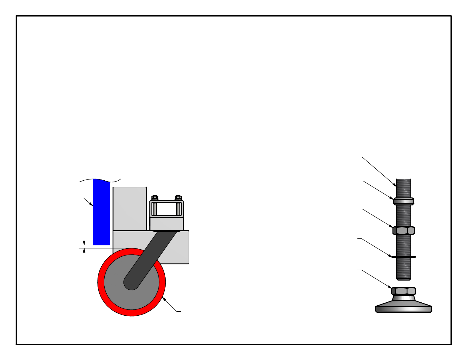
REPLACING THE SHIPPING FEET
The front feet that are supplied with this unit are for transportation purposes, as they are subject to unusual wear and tear. An additional set
of permanent feet have been supplied and should be installed prior to placing the unit on the finished sports floor. After the new feet are
installed, ensure that the jam nut on each is securely tightened.
ATTACHING THE LOWER FRONT AND SIDE PROTECTION PADS
Additional mounting brackets have also been provided for installing the lower front pad and both side pads. These brackets are provided to
increase the holding capacity.
When installing the lower front pad refer to the illustration below to establish its proper height.
FRONT FEET ROD SCREW
FRONT FEET PAD SCREW
FRONT PAD
1/8" ~ 3/8"
1"-8 JAM NUT
1”-8 INTERNAL LOCK WASHER
4" DIA x 1 7/8" LEVELING FEET
SWIVEL CASTER
ROTATED SO WHEEL STICKS OUT BEYOND FRAME

JAYPRO ELITE SERIES ADJUSTABLE PORTABLE BACKSTOPS
Installation and Operating Instructions
Applicable Part Numbers/Models:
PBEL54: Jaypro Elite 5400
PBEL66: Jaypro Elite 6600
PBEL96: Jaypro Elite 9600
JSL-Inst039
www.jayprosports.com

ELITE Series Adjustable Portable Backstop Instructions
Table of Contents
1 Safety ................................................................................................................ 2
2 Specifications .................................................................................................. 2
3 Introduction ..................................................................................................... 2
4 Required Tools ................................................................................................. 3
5 Included Hardware & Components ............................................................ 3
5.1 Miscellaneous Hardware ...................................................................... 4
5.2 Locating devices .................................................................................... 4
5.3 Anchor Kit (PBELKIT) ................................................................................ 4
5.4 Backboard .............................................................................................. 5
5.5 Backboard hardware kit ....................................................................... 5
5.6 Rim ............................................................................................................ 6
6 Installing Backboard/Rim .............................................................................. 7
7 Unpacking ..................................................................................................... 12
8 Set Foot Stops ................................................................................................ 13
9 Padding Installation ..................................................................................... 15
9.1 Included Padding ................................................................................ 16
9.2 PBEL66/96 Padding Installation .......................................................... 17
9.3 PBEL54 Padding Installation ................................................................ 20
10 Installing Locating Devices ......................................................................... 21
10.1Installation of Locating Bushings ....................................................... 22
10.2Location of Locating Stickers ............................................................ 24
11 Installing Anchor Kit ...................................................................................... 24
12 Raising/Lowering Backstop ......................................................................... 25
12.1Raising Backstop ................................................................................. 26
12.2Lowering Backstop ............................................................................. 27
13 Spring Adjustments ....................................................................................... 27
14 Maintenance ................................................................................................ 28
- 1 of 28-
JSL-Inst039
www.jayprosports.com

ELITE Series Adjustable Portable Backstop Instructions
1 Safety
IMPORTANT: LIFT-ASSIST SPRINGS UNDER EXTREME TENSION. DO NOT ADJUST SPRINGS
WITHOUT CONSULTING MANUAL, SEE SECTION 13 (PAGE 27).
IMPORTANT: DO NOT REMOVE SAFETY STRAP OR QUICK-RELEASE PIN UNTIL THE
BACKBOARD AND RIM HAVE BEEN INSTALLED. FAILURE TO COMPLY MAY RESULT IN
SEVERE OR FATAL INJURY AS WELL AS SIGNIFICANT DAMAGE TO SURROUNDING
STRUCTURES.
Follow all warning labels on backstops.
Do not stand directly behind uprights when raising or lowering the backstop.
Be sure that area within 8 feet (2.5 meters) of backstop is clear of bystanders before
raising or lowering.
Obtain assistance if lifting/lowering operation is too strenuous.
Do not use backstop unless it is pinned at game-height using the supplied quick
release pin.
Unit must be pinned in position using supplied quick-release pin at all times unless
raising or lowering.
When raising or lowering, do not release handles until backstop has been pinned in
position with the sup plied quick-release pin.
Do not attempt to remove the backboard unless the unit is pinned in position with the
supplied quick-release pin.
Do not hang on rim.
Do not use power tools to raise or lower feet.
Do not use backstop for gameplay unless feet have been lowered to game height.
Inspect backstop for damage before and after each use.
2 Specifications
Extension Ballast
Jaypro Elite
9600 96” 1000 lbs
Jaypro Elite
6600 66” 800 lbs
Jaypro Elite
5400 54” 800 lbs
Backboard
1
Standard
GBRUB-42
(42” x 72”) GBA-18042 2,600 lbs
GBRUB-42
(42” x 72”) GBA-642 2,400 lbs
GBRUB-54
(42” x 54”) GBA-642 1,600 lbs
2
Standard
Rim
Total
Weight
3 Introduction
This guide describes the installation and use of the ELITE Series Adjustable
Portable Backstops, models PBEL54, PBEL66, and PBEL96.
1
When PBEL54 shipped with 72” board (optional upgrade), 1000 lbs of ballast is included.
2
GBRUB-42 available as optional upgrade, must be specified at time of order
- 2 of 28-
JSL-Inst039
www.jayprosports.com

ELITE Series Adjustable Portable Backstop Instructions
The sections of this guide that detail the initial setup of the backstops is
written with experienced mechanical contractors/installers in mind. If you
require additional information or support to install your backstops, please
contact the Jaypro Sports customer support team, Monday through
Friday, 8:30AM to 5:00 PM (EST), at 1-800-243-0533.
The guide is organized in the order of operations required for initial
assembly, installation, and setup. The installer is responsible to carry out
the procedures described in sections 1 through 11. Section 12 describes
the procedure for raising and lowering the backstop and is intended to
be used by the end-user. Section 13 describes the procedure for
adjusting the lift-assist springs and should only be used by an experienced
contractor/installer. Please contact the Jaypro Sports customer support
team, Monday through Friday, 8:30AM to 5:00 PM (EST), at 1-800-243-0533
if assistance with locating an experienced professional is required.
4 Required Tools
Before continuing, please verify that you have the following tools required
to complete the installation and setup of your Elite series adjustable
portable backstop.
Socket wrench with 24mm deep socket (supplied)
Hex wrench (3/16”)
Adjustable wrench
#2 Phillips screwdriver
Level
7/8” Transfer punch (recommended)
1-1/8” hole saw
1-3/8” hole saw
Adhesive suitable for metal-to-wood bonding
Sandpaper, 180 – 320 grit
5 Included Hardware & Components
Before continuing, please verify that you have all the required hardware
(included w/ unit) for installation and setup. If any of the following items
are missing, contact the Jaypro Sports customer support team, Monday
through Friday, 8:30AM to 5:00 PM (EST), at 1-800-243-0533.
- 3 of 28-
JSL-Inst039
www.jayprosports.com

ELITE Series Adjustable Portable Backstop Instructions
5.1 Miscellaneous Hardware
Figure 5-1: Quick-release pin for height adjustment (1X)
5.2 Locating devices
Figure 5-2: Locator Pin Bushing (2X) Figure 5-3: Locator Pin (2X) Figure 5-4: Wire-snap safety
Figure 5-5: Locating Sticker (2X)
pin for locator pins (2X)
5.3 Anchor Kit (PBELKIT)3
Figure 5-6: FP-89 Floor Anchor (1X) Figure 5-7: Cover plate (for flaoting wood floors only)
3
Included with PBEL96, optional on PBEL66 & PBEL54, see catalog for ordering information
- 4 of 28-
JSL-Inst039
www.jayprosports.com

ELITE Series Adjustable Portable Backstop Instructions
Figure 5-8: ½"-13 Eyebolt w/
shoulder (1X)
5.4 Backboard
Shackle (2X)
Figure 5-9:
Figure 5-10: Twisted chain (8”)
Figure 5-11: Backboard (72" board supplied w/ PBEL96 & PBEL 66, 54" with PBEL54)
Figure 5-12: Left (viewed from court) backboard
support arm (1X).
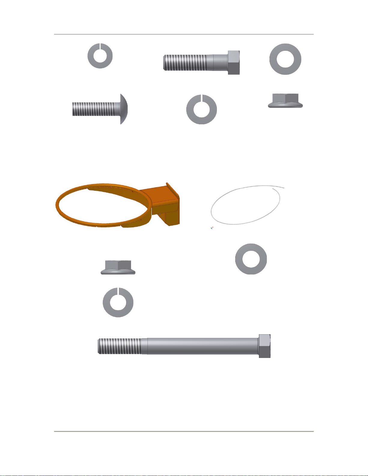
5.5 Backboard hardware kit
Figure 5-14: 5/16”-18 Flanged Hex Nuts
(2X)
Figure 5-15: 5/16”-18 x 1-1/8” Carri ag e
www.jayprosports.com
Figure 5-13: Right (viewed from court) backboard
Bolt (2X)
- 5 of 28-
JSL-Inst039
support arm (1X).
Figure 5-16: 5/16” Flat
Washer (2X)
ELITE Series Adjustable Portable Backstop Instructions
Figure 5-17: 5/16” Split Washer (2X) Figure 5-18: 3/8”-16 x 1-1/2” Hex Bolt (2X) Figure 5-19: 3/8” Flat
Figure 5-20: 3/8”-16 x 1” Carriage Bolt
(2X)
Figure 5-21: 3/8” Split Washer (2X) Figure 5-22: 3/8”-16
Washer (2X)
Flanged Hex Nuts (4X)
5.6 Rim
Figure 5-23: Breakaway Rim (1X, model varies) Figure 5-24: Nylon Net Tie (1X)
Figure 5-25: 3/8”-16 Flanged Hex Nuts (4X) Figure 5-26: 3/8” Flat Washer (4X)
Figure 5-27: 3/8” Split Washer (4X)
Figure 5-28: 3/8” x 4-1/2” Hex Bolt (4X)
- 6 of 28-
JSL-Inst039
www.jayprosports.com
ELITE Series Adjustable Portable Backstop Instructions
6 Installing Backboard/Rim
WARNING: DO NOT REMOVE SAFETY STRAP OR QUICK-RELEASE PIN UNTIL THE BACKBOARD
AND RIM HAVE BEEN INSTALLED. FAILURE TO COMPLY MAY RESULT IN SEVERE OR FATAL
INJURY AS WELL AS SIGNIFICANT DAMAGE TO SURROUNDING STRUCTURES.
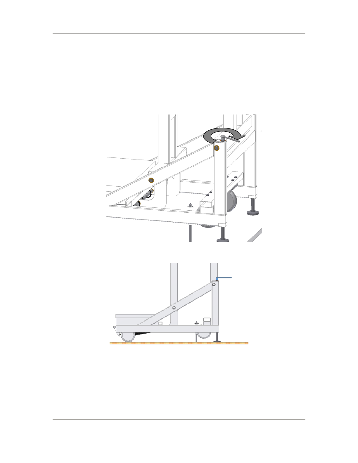
1. Lower both feet (Figure 6-1) using the supplied socket wrench until
both side 2-by-4’s of the base are level (Figure 6-2).
Figure 6-1: Lower feet using supplied socket wrench.
Figure 6-2: Lower feet until bottom horizontal 2" x 4" ‘s are level.
2. Attach left and right backboard support arms to slots in boom using
the 5/16”-18 x 3/4” carriage bolts (2X), 5/16” flange nuts (2X), 5/16”
flat washers (4X), and 5/16” split washers (2X) as shown in Figure 6-3.
Hand-tighten the nuts; do not use a wrench.
- 7 of 28-
JSL-Inst039
www.jayprosports.com
 Loading...