

Page 1

18” Quilting Machine
Instruction Manual
Page 2

Congratulations on your purchase of a Janome Quilt Maker Pro 18
from Janome!
Congratulations on your purchase of the Janome Quilt
Maker Pro and welcome to the Janome family.
Our mission is to produce machines which inspire
creativity and innovation, yet are simple to use. The
better your tools, the more inventive and pleasurable
your sewing experience. We know the most important
thing about our products is not the machines
themselves, but what you create with them. That’s why
we design our machines for performance, but also for
comfort, quality, and intuitive ease of operation.
Package Contents
Please keep your original box and packaging
As a leader in the sewing industry, we keep striving to
provide best-in-class products and services which enable
sewists’ creativity and innovation. Please be sure to
register your warranty on janome.com. Your registration
allows us to communicate with you regarding machine
updates and other product information. In addition, our
website offers tutorials, quilting patterns, videos, and
more educational materials for your Quilt Maker Pro.
Remember, if you ever have questions, your local
Janome Dealer can help you. For general questions,
please use the General Inquiries Form on janome.com
or call Monday through Friday 8:30AM - 5:00PM EST,
1-800-631-0183 option 3.
Contents of Package
1. Bobbins (5 pieces, one in machine)
2. Needle (135x5) size 16 (pack of 10)
3. Needle (135x5) size 18 (pack of 10)
4. Bobbin Case
5. Thread Mast
6. Pin Oiler
7. Lint Brush
8. Screwdriver
9. Power Cord
10. 2.5 mm L Allen tool
11. Laser Stylus and Clamp
12. Laser Stylus Post
13. Open-toe Foot
14. User Manual
15. Quilt Maker Pro 18 Quilting Machine
Optional Accessories
1. 18” Machine Ruler Base
2. 11’ Leader Set
3. Set of 8 Casters
4. Hand Wheel Kit
5. Channel Locks
6. Couching Feet Set
7. Glide Foot
8. Echo Feet Set
9. Horizontal Spool Pin
10. Bobbin 8 Pack
11. Bobbin Case
Page 2
Quilt Maker Pro 18 User Manual
201704
Page 3

Table of Contents
Safety ................................................................................................................................................................................................................... 4
Components (Front Side View) ................................................................................................................................................................. 7
Components (Back Side, Rear and Front Views) ............................................................................................................................... 8
Installation (Frames) ......................................................................................................................................................................................9
Installation (Handlebars) .............................................................................................................................................................................. 9
Installation (Power Cord) ........................................................................................................................................................................... 10
Inserting Needle .............................................................................................................................................................................................11
Changing the Feet .........................................................................................................................................................................................12
Laser Stylus ......................................................................................................................................................................................................13
Installation (Thread Mast) .......................................................................................................................................................................... 14
Threading the Machine ................................................................................................................................................................................15
Horizontal Spool Pin .....................................................................................................................................................................................17
Bobbin and Thread Tension Adjustments .............................................................................................................................................17
Easy-Set Tension™ Adjustment ................................................................................................................................................................ 19
Maintenance (Oiling and Lubricating) ................................................................................................................................................... 19
Touch Screen Displays ............................................................................................................................................................................... 20
System Information ......................................................................................................................................................................................27
Diagnostics Tests ..........................................................................................................................................................................................28
Janome Stitch Regulator Operation .......................................................................................................................................................31
Getting Started Quilting ............................................................................................................................................................................. 32
Quilt Maker Pro 18 Troubleshooting .......................................................................................................................................................33
Bobbin Winder ...............................................................................................................................................................................................39
Warranty Information .................................................................................................................................................................................. 52
janome.com
Page 3
Page 4

Safety Section
This device complies with Part 15 of the FCC Rules.
Operation is subject to the following two conditions:
(1) This device may not cause harmful interference, and
(2) this device must accept any interference received,
including interference that may cause undesired
operation.
Please note: Do not operate your Janome Quilt Maker
®
Pro 18
the information contained in this manual. Please keep all
packaging and order information for warranty purposes.
IMPORTANT SAFETY INSTRUCTIONS
Read all instructions before using this machine.
When using this machine, basic safety precautions
should always be followed, including the following:
DANGER — To reduce the risk of electric shock:
• A quilting machine should never be left unattended
WARNING — To reduce the risk of burns, fire, electric
shock, or injury to persons:
• The Janome Quilt Maker Pro 18
• Always unplug the Janome Quilt Maker Pro 18
• Do not unplug by pulling on cord. To unplug, grasp
• Keep fingers away from all moving parts. Use caution
• Change the needle often. Do not use bent or dull
• Switch the machine to the symbol off, or 0, position
• Never drop or insert foreign objects into any
• The Janome Quilt Maker Pro 18
• The Janome Quilt Maker Pro 18
• Use the Janome Quilt Maker Pro 18
• To disconnect from the wall outlet, push the switch
quilting machine until you have completely read
when plugged in. Always unplug the machine from
the electrical outlet immediately after using and
before cleaning.
®
is heavy. Never
attempt to lift it alone. Always use two people when
lifting. Always lift from the throat of the machine, not
from the handlebars.
®
from the electrical outlet when performing any
maintenance, changing the needle, removing thread
locks, or when left unattended.
the plug, not the cord.
around the needle or sharp external components.
needles. “Every quilt deserves a new needle”.
to turn it off when making any adjustments in the
needle area, such as threading needle, changing
needle, threading bobbin, changing hopping foot,
and so forth.
opening.
®
should only be used
indoors away from moisture.
®
should not be stored
or used in extreme temperatures.
®
only for its
intended use as described in this manual.
to the off position, then remove the plug from outlet
pulling from the plug, not the cord. Never operate the
Janome Quilt Maker Pro 18
®
if the cord is damaged
or not working correctly. If a mechanical or electrical
problem is encountered, return the Janome Quilt
Maker Pro 18
®
to the nearest authorized service
center or the manufacturer for examination, repair,
electrical, or mechanical adjustment.
• It is not recommended that the Janome Quilt Maker
®
Pro 18
quilting machine be used with any machine
quilting frame other than those recommended by
Janome.
• Use this quilting machine only for its intended use
as described in this manual. Use only attachments
recommended by the manufacturer as contained in
this manual.
• Never operate the machine with any air openings
blocked. Keep ventilation openings of the machine
free from the accumulation of lint, dust, and loose
cloth.
• Do not operate where aerosol (spray) products are
being used or where oxygen is being administered.
• Do not pull or push the machine across the fabric
excessively while stitching. It may deflect the needle
enough to cause it to break.
• Use only needles designed for free motion quilting
and recommended by Janome for this machine.
Other types of needles may be break during normal
quilting.
• Children shall not play with the machine. Close
attention is necessary when this machine is used by
or near children.
• This sewing machine may be used by children age 8
years and above and persons with reduced physical,
sensory, or mental capabilities or lack of experience
and knowledge if they have been given supervision
or instruction concerning use of the machine in a safe
way and understand the hazards involved.
• Cleaning and user maintenance shall not be made by
children without supervision.
Save these instructions.
This machine is intended for household or commercial
use.
Disclaimer
Janome and its Representatives are in no way legally
responsible or liable for damage to the Janome Quilt
Maker Pro 18 when used improperly or not in accordance
with the guidelines stated in this manual or when used
on machine quilting frames not recommended by
Janome.
Page 4
Quilt Maker Pro 18 User Manual
201704
Page 5

To use the machine safely
1. Carefully watch the needle when sewing. Do not
touch the hand wheel, take up lever, needle, or other
moving parts.
2. Turn the machine off and unplug the cord in the
following cases:
• when you have stopped using the machine
• when you replace or remove the needle or any
other part
• when you check or clean the machine
• when you leave the machine unattended
3. Connect the machine directly to the wall outlet or to
a surge protector that connects directly to the wall
outlet. Do not use extension cords.
To increase the life of your machine
1. Do not store this machine in areas exposed to direct
sunlight or high humidity. Never use or store the
machine near a heater, an iron, a halogen lamp or
other hot things.
2. Use only neutral soaps or detergents to clean the
machine. Benzene, solvents and scouring powders
can damage the case and the machine and therefore
should never be used.
3. Do not drop or bump the machine.
4. Always consult the manual to replace or fix the
hopping foot, needle or any other part of the
machine. If necessary contact an authorized Janome
representative or Janome technical support.
General Specifications
The Janome Quilt Maker Pro 18 utilizes high-tech
electronics and an innovative touch-pad user interface
to offer greater functionality and ease of operation to
home quilters than ever before conceived in the quilting
industry. The Janome
is a high quality machine that incorporates very robust
design features and is very easy to service.
Sewing Opening Dimensions:
Sewing Speed:
Stitches-Per-Inch:
Needle System:
Needle Sizes (recommended):
Hook System:
Bobbin Type:
Bobbin Case:
Motor Ty pe:
Needle Positioning:
Electrical Power:
LED Power Consumption:
Sew Foot Stroke/Lift:
Needle Bar Stroke:
Take-Up Stroke:
Lubrication, main components:
Lubrication of hook:
Quilt Maker Pro 18 quilting machine
(245 mm X 610 mm) 8.25” X
18”
Manual Mode:
Min 90spm, Max 2,200spm
Regulated Mode:
Min 0spm, Max full speed
4spi – 22spi
134 (135 X 7)
12/80 - 20/125
Rotary, Horizontal axis, M-class
bobbin
Aluminum, Class M
Type MF
Brushless DC
Up and down, walking stitch
100 – 240 VAC, 50 - 60Hz,
300W peak
(1.69A@100/.9A@240)
8 W
5 mm
35.3 mm
73 mm
Kluber Lube, permanent
Velocite 10, Texaco 22
janome.com
Disclaimer
Janome and its Representatives are in no way legally
responsible or liable for damage to the Janome
Quilt Maker Pro 18 when used improperly or not in
accordance with the guidelines stated in this manual
or when used on Machine Quilting Frames not
recommended by Janome.
Page 5
Page 6
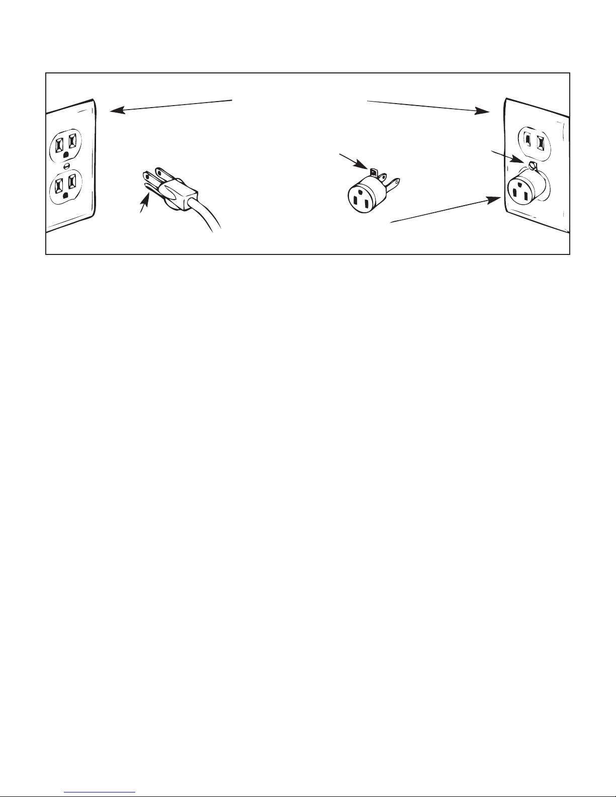
Optional U.S. Grounding
for Customers with 120 VAC Connections
GROUNDED OUTLET
BOXES
TAB FOR
GROUNDING
SCREW
GROUNDING
PIN
(A)
This product is for use on a nominal 120 V or nominal 220 V circuit, and has a grounding plug that looks like the
plug illustrated in sketch A above. A temporary adapter, which looks like the adapter illustrated in sketches B and
C, may be used to connect this plug to a 2-pole receptacle as shown in sketch B if a properly grounded outlet is
not available. The temporary adapter should be used only until a properly grounded outlet can be installed by a
qualified electrician. The green colored rigid ear, lug, and the like, extending from the adapter, must be connected to
a permanent ground such as a properly grounded outlet box cover. Whenever the adapter is used, it must be held in
place by the metal screw.
ADAPTER
(B)
METAL
SCREW
(C)
IMPORTANT: In Canada, the use of a temporary adapter is not permitted by the
Canadian Electric Code.
To repair or adjust the machine
If the machine breaks down or needs adjustment, first check the troubleshooting chart in the appendix to inspect
and adjust the machine yourself.
For more product information and updates, visit our website at www.janome.com/qmp18.
The contents of this manual and product specifications are subject to change without prior notice.
Check for updated manuals at www.janome.com/qmp18.
Page 6
Quilt Maker Pro 18 User Manual
201704
Page 7
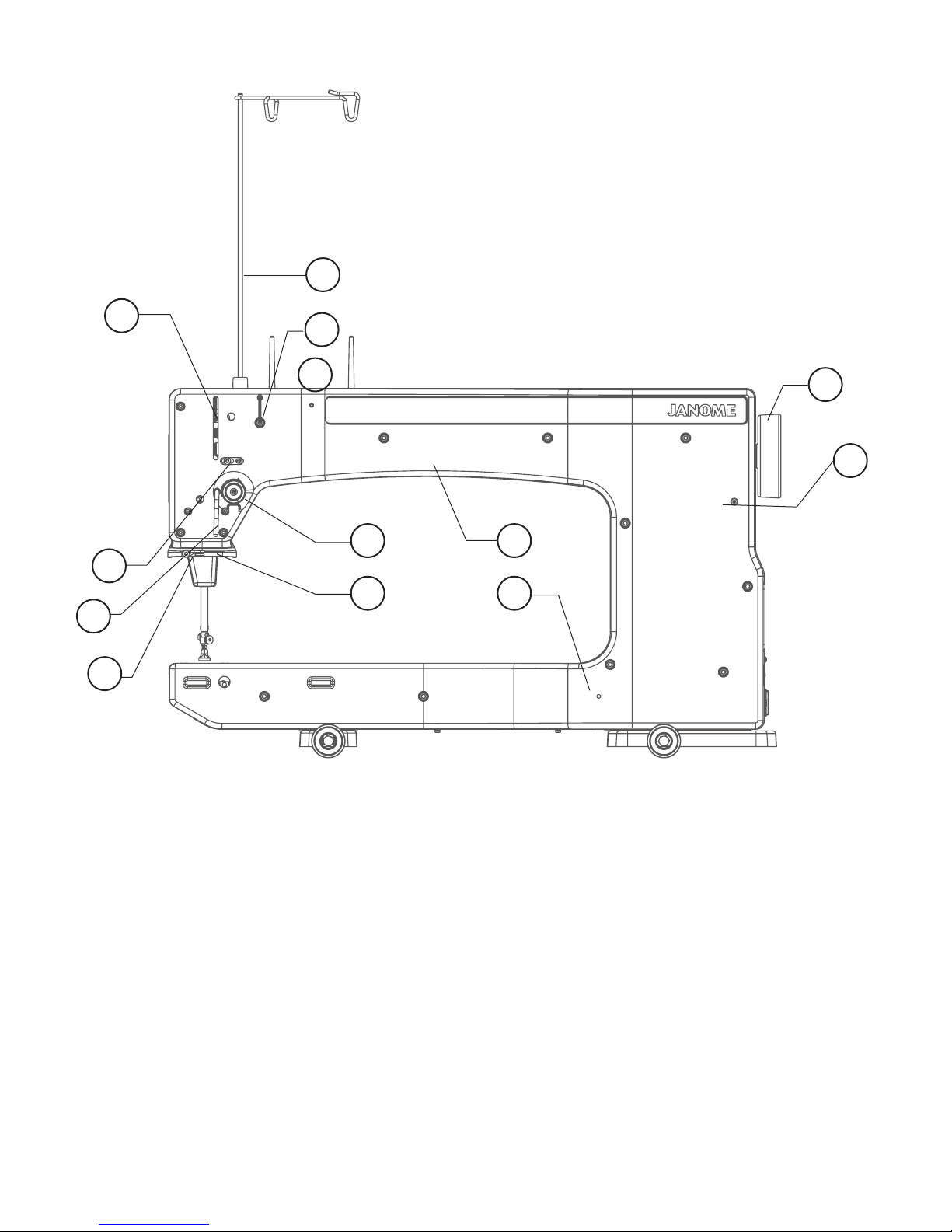
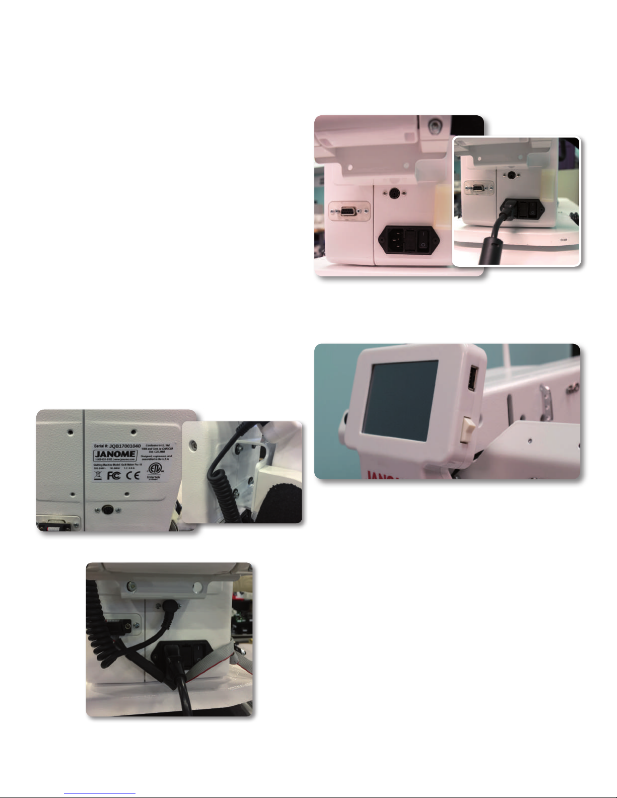
Janome Quilt Maker Pro 18 Components
Front Side View
1
8
4
6
7
3
2
5 10
8 12
11
13
1. Thread Mast
2. Thread Guide A
3. Three Hole Thread Guide B
4. Thread Guide C
5. Tension Assembly
6. Stirrup Thread Guide D
7. Thread Guide E
8. Take-Up Lever
9. Thread Guide F
10. Front Casing/Frame
11. Handwheel
12. Side Laser Stylus Post Hole
13. Laser Stylus Power Connector
janome.com
Figure 1
Page 7
Page 8
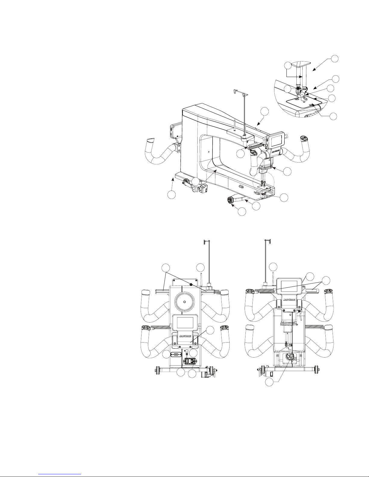
Janome Quilt Maker Pro 18 Components
Back Side View
14. Ruler Foot
15. Needle
16. Needle Bar Thread Guide
17. Needle Bar
18. Presser Bar
19. Feet Mount
20. Needle Plate
21. LED Light Ring
22. Front Handlebar Connector
23. Ruler Base Position Guides
24. Front Wheel Base
25. Wheels (4)
26. Back Casing/Frame
27. Rear Wheel Base
28. Horizontal Spool Pin Hole*
27
26
22
25
Figure 2
24
28
17
18
16
19
21
23
15
14
20
Rear and Front Views
29. Spool Pin 1
30. Magnets
31. Serial Port for Stitch Regulator
32. Rear Handle Bar Serial Port
33. Rear Threaded Handles
34. LED Modules
35. Power Cord Connector
36. On/Off Switches
37. Spool Pin 2
38. Bobbin Assembly
Rear
34
31
36
32
35
37
33
Front
Figure 2.1
38
29
35
30
* Horizontal Spool Pin is an optional accessory. Please contact your local Janome dealer to purchase.
Page 8
Quilt Maker Pro 18 User Manual
201704
Page 9
Installation (Quilt Maker Frame)
1. Place the carriage, wheels down, on the table rails,
ensuring that the Carriage Encoder Assembly (small
black box) is positioned on the opposite side from the
frame poles. Be sure to place the carriage on the frame
correctly (see Figure 3).
2. Place the machine on the carriage with the back of
the machine on the same end as the Carriage Encoder
Assembly. Be sure that the silver rails on the carriage
are inserted into the groove in the machine wheels.
3. On the rear of the machine there is a ribbon cable
attached and folded up. Unfold the ribbon cable and
plug the unattached end of the ribbon cable from the
machine into the Carriage Encoder Assembly. The
connector is keyed to assure correct alignment. Make
sure the keyed portion of the cable connector aligns
with the keyed portion of the encoder connector. Do
not force.
5. REMEMBER that if the machine is to be removed
from the carriage, the cable must be disconnected
from the Carriage Encoder Assembly. The other
two connectors on the cable should remain in place.
Failure to unplug the cable when removing the
machine from the carriage could result in damage to
the cable, encoders, and carriage.
Figure 3
Installing Front Handlebars
Caution: Unplug the Janome Quilt Maker Pro 18 from
the electrical outlet. All power to the machine must be
turned off when installing the front handles. Failure to do
so can result in damage to the machine.
Locate the handlebar with lights and magnets attached—
this is the front handlebar. On the front of the machine
locate the 4 threaded holes in a square pattern. (See
Figure 4) Use the 4 bolts found in the machine accessory
box in the small bag with the black spiral serial cables
to attach the front handlebar mounting plate using the
included 4mm hex wrench.
Find the serial connection point on the left side of the
front display and the serial connection point on the
left side of the front of the machine. Connect the front
display to the machine using one of the black spiral serial
cords. (See Figure 4.1) Be careful to align the pins in the
cord with the pins in the serial connection points. Insert
carefully.
Handlebars can rotate to desired position by loosening
the bolts and rotating the handlebars being sure to not
pull them out.
Figure 4
Note: There are magnets on the reverse of the lighting
for convenient storage.
janome.com
Figure 4.1
Page 9
Page 10
Installing Rear Handlebars
Installing the Power Cord
Check that the Janome Quilt Maker Pro 18 is unplugged
from the electrical outlet. All power to the machine must
be turned off when installing the back handlebar. Failure
to do so can result in damage to the machine.
Locate the handlebar without lights and magnets
attached –that is the rear handlebar. On the back of the
machine locate the 4 threaded holes in a square pattern.
(See Figure 4.2) Use the 4 bolts found in the machine
accessory box in the small bag with the black spiral serial
cables to attach the rear handlebar mounting plate using
the included 4mm hex wrench. The mounting plate has
4 access holes for the hex wrench to tighten the bolts.
(See Figure 4.2)
Find the serial connection point on the left side of the
rear display and the serial connection point on the rear
of the machine. Connect the rear display to the machine
using one of the black spiral serial cords. (See Figure
4.3) Be careful to align the pins in the cord with the pins
in the serial connection points. Insert carefully.
Note: After the handles have been completely installed
and plugged in, test them by turning the Janome Quilt
Maker Pro 18 on/off switch to “on”. You will not be
able to turn on the machine until the front handlebars
are installed. If nothing is displayed, check that the
handlebar cable on the side of the machine is plugged
in securely, that your machine is turned on, and that
the power cord is plugged into the machine as well as a
power source.
Insert the cord into power connector on the rear of the
machine. Plug the three-prong end into a power source
(see Figure 5).
Figure 5
Turning on the Janome Quilt Maker Pro 18
Figure 4.2
Figure 4.3
Page 10
Figure 6
There are two power switches for your machine. The
main power switch is at the rear of the machine and
a white power switch is on the right side of the front
screen for your added convenience.
(Figure 6)
The machine is turned on when both switches are turned
on. The machine is turned off when both switches are
off. However, you may turn off the machine functions by
turning off only the front switch if you will be returning
to quilt within a day.
Turn on the back switch first by toggling the switch from
the 0 position to the 1 position. Then turn on the front
switch by toggling it as well. The front switch will not
turn on the machine unless the back switch is already on.
IMP O RTAN T: If you will not be using the machine for
more than a day, we recommend you turn off both
switches and unplug the power cord from the power
source.
IMP O RTAN T: Refer to the safety instructions.
Quilt Maker Pro 18 User Manual
201704
Page 11
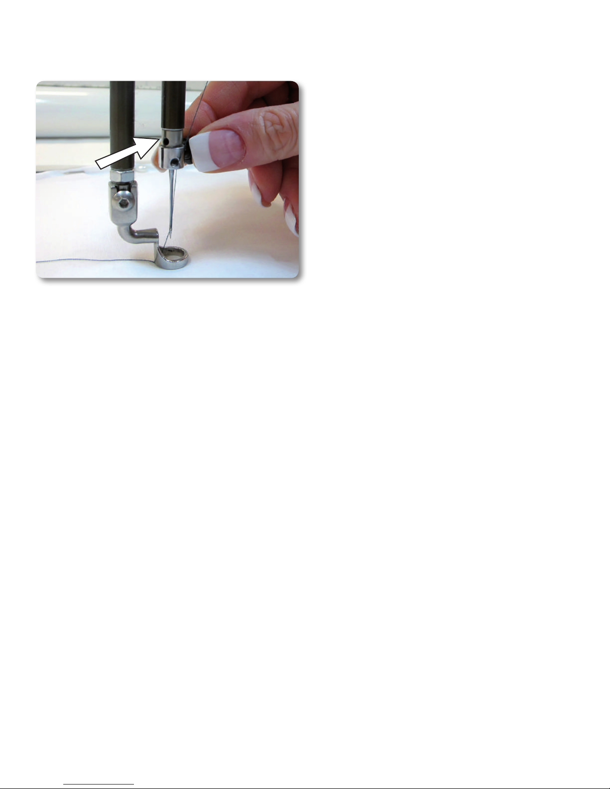
Inserting (or changing) the Needle
SIGHT
HOLE
Figure 7
1. Check that all power is turned off.
2. Move the needle bar to the highest position by turning
the hand wheel or by pressing the needle up/down
control on the handles (prior to turning the power
off).
3. Loosen the needle-bar clamp thumb screw (Figure 7).
4. With the scarf (small ground out section/dip on the
back side of the needle just above the needle eye)
facing the rear hand wheel side of the machine, and
the long groove down the front of the needle facing
the bobbin case side (see Figure 7), push the needle
all the way up into the needle bar – until it can go no
farther. Look into the sight hole to verify that the butt
of the needle reaches the top of the sight hole.
5. Carefully tighten the needle bar clamp screw. Over
tightening the needle clamp screw will result in
damaged threads stripping the hole. Stripped holes
are not covered under warranty. Another side effect
of damaged threads from over-tightening that the
needle may be very tight when inserted up into the
needle bar. To avoid over-tightening the screw, finger
tighten only.
NOTE: Changing the needle is recommended for each
new quilt loaded on the machine or any time the needle
becomes bent, dull or burred.
IMP O RTAN T: Check the needle to confirm that it is fully
inserted. The needle bar has a stop/sight hole above
the needle bar clamp screw – make sure the needle is
touching the top of the stop/sight hole (Figure 7). If
it is not, the machine timing will be off and it may be
possible for the needle to collide with internal parts
causing damage not covered by warranty.
CAUTION: Your Janome machine stitches at a much
faster speed than your home sewing machine.
Therefore it is essential that the needle is firmly
seated in the needle bar and fully tightened (but not
over tightened). Check often that the needle has not
become loose. If the needle comes loose, it could
break in the machine causing damage, throw off the
machine’s timing, or worse, cause bodily harm.
janome.com
Page 11
Page 12
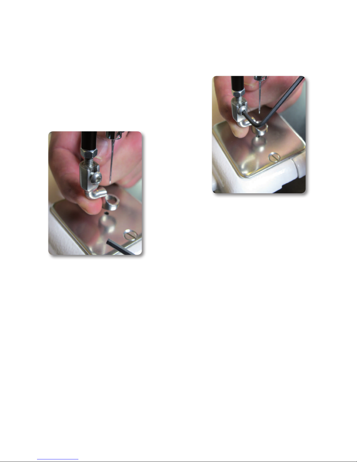
Changing the Feet
Your machine came with two Feet: a ruler foot and an
open-toe foot. Use the ruler foot for ruler work and
everyday quilting, and the open-toe foot when you need
greater stitch visibility (such as micro quilting). Other
Feet are available, such as the Couching Foot Kit.
1. Remove the foot that is on the mount by using the
2.5mm hex wrench to loosen the mounting screw far
enough that you can slide the foot off of the mount.
2. Slide the desired foot onto the mount (figure 8). Note
that the opening on the side of the foot is lined up
with the screw hole. Push the Foot up as far as it will
go.
3. Ensure the foot is centered with the needle when the
foot is fully tightened with the 2.5mm hex wrench. If
it isn’t properly centered, loosen the lock nut; center
the foot with the needle; hold the foot in position; and
firmly tighten the lock nut (Figure 9).
Figure 9
Figure 8
Page 12
Quilt Maker Pro 18 User Manual
201704
Page 13
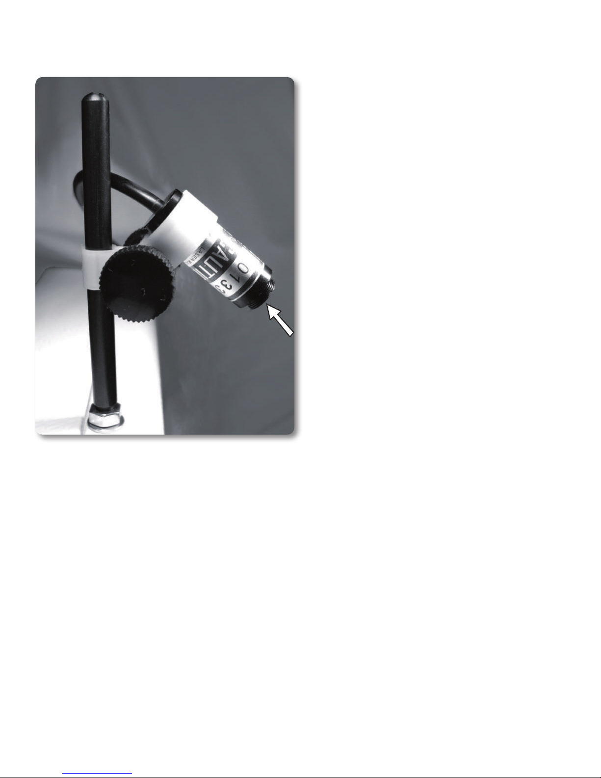
Laser Stylus Safety and Use Guidelines
The laser stylus projects a straight laser beam visible as
a dot on surfaces it hits. The laser dot is used as a guide
or stylus, allowing you to stitch the same pattern onto a
quilt that is being traced with the laser dot.
Laser Operation and Use
There is not a separate on/off switch for the laser. Power
is supplied to the laser when it is plugged into the
Janome Quilt Maker Pro 18. Be sure the laser is attached
to the Janome Quilt Maker Pro 18 and pointed downward
toward the table before connecting it to the port. Never
point it in a direction that would project the beam into
someone’s eyes. If the laser should cease to operate,
check to ensure the plug is firmly seated into the Janome
Quilt Maker Pro 18 laser port.
CAUTION: Use of controls or adjustments or
performance of procedures other than those specified
herein may result in hazardous radiation exposure.
Figure 10
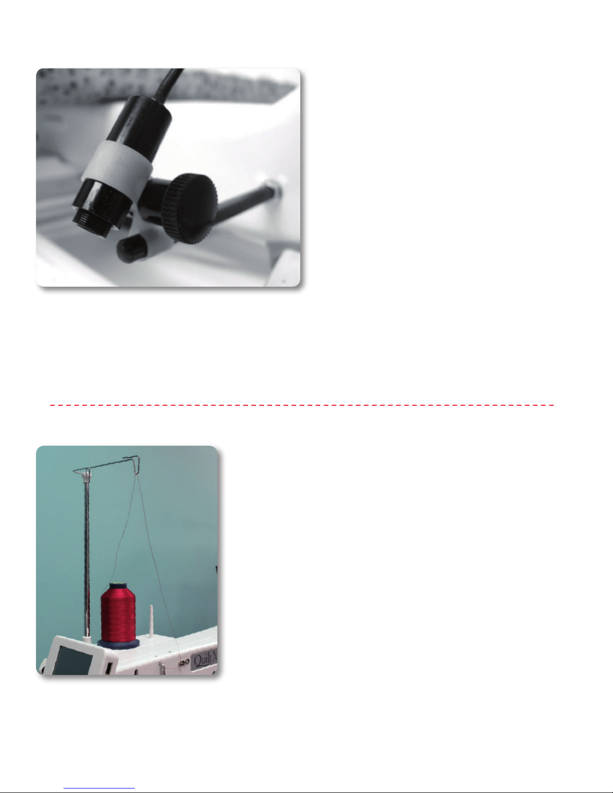
Laser Focus/Laser Image Size
This high quality laser is focusable. The laser is focused
by simply grasping the threaded housing surrounding
the lens and turning clockwise or counter-clockwise (see
Figure 10). The laser image can be adjusted bigger or
smaller. The direction of rotation needed is determined
by the distance of the laser from the intended focal
plane. Experiment by turning the threaded end to
achieve your desired focal size.
Clamp Adjustment
The laser attaches to a mounting post. The post may be
vertical or horizontal. The clamp is designed to articulate
in any direction by rotating the clamp on the post and
pivoting the laser up or down. To make an adjustment,
simply loosen the black thumbscrews, position, and
retighten.
Location of Laser Labels
The label is attached to the case of the laser and
contains an arrow which indicates the direction the laser
light will shine when energized. The label must remain
in place on the laser. Removal of the label will void the
laser’s warranty.
janome.com
Page 13
Page 14
Installing the Laser Stylus
Figure 11
To attach the laser stylus to the machine:
1. Locate the threaded hole on side of the machine
near the handwheel (see Figure 1, #12, page 7). The
laser stylus guide post comes with the washer and
nut on it. Remove the nut and washer, replace the
nut onto the post and then place the washer under
the nut and onto the machine painted surface. The
washer protects the painted surface when the nut
is tightened. Tighten the post clockwise until it is
securely in place. Use the nut to secure the post to the
machine.
2. Be sure the laser stylus is inserted into the laser
clamp.
3. Slide the laser clamp over the post to the desired
height.
4. Plug the laser power cord into the port on the rear
side of the machine. (see Figure 1, #13, page 7).
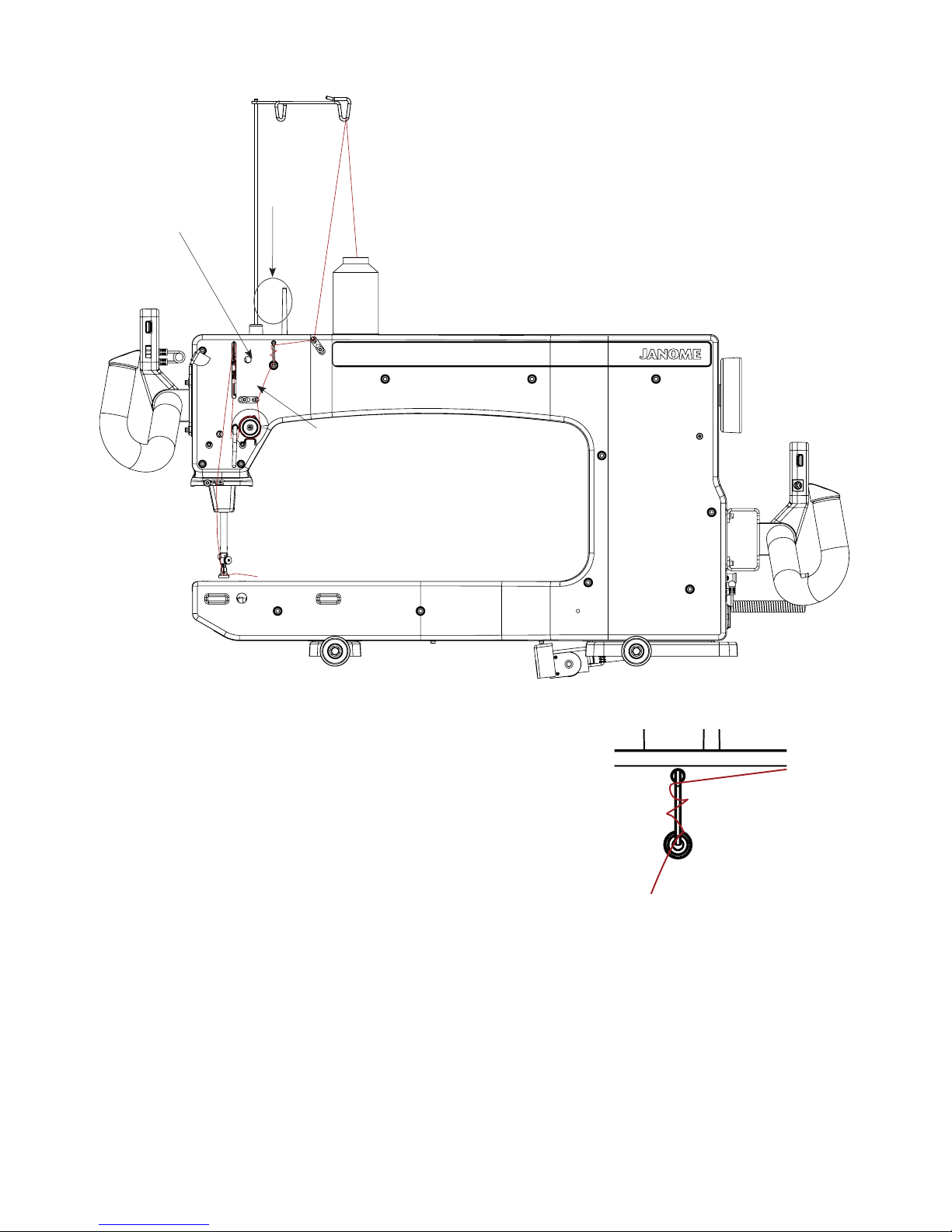
Installing the Thread Mast
Figure 12
1. Find the two threaded holes located towards the front
of the upper machine arm. Attach the plastic thread
stand by placing two screws through the holes on the
side of the thread stand and attaching those screws
into the two threaded holes on the side of the upper
machine arm.
2. Remove the screw from the bottom of the thread mast
and place it in the thread stand socket on the front
corner of the thread stand. Secure the thread mast
by placing the removed screw through the underside
of the thread stand and into the bottom of the thread
mast.
Page 14
Quilt Maker Pro 18 User Manual
201704
Page 15
Threading the Machine
Guide
Take Up Spring
B
Tension Assembly
Figure 13
1. Place a cone or spool of thread on the spool pin. Pass
the thread through the thread-mast eyelet from back
to front, continuing to thread guide A. (Figure 13)
2. Continue to the three-hole thread guide B. Wrap all
three holes from back to front, hand wheel side to
needle side. (Figure 14).
Note: The purpose of the three-hole thread guide B is
to prevent loops of thread coming off the thread cone
from going into the top tension as a knot causing thread
breakage and bad tension. For most threads on a cone,
it is important to thread all three holes for consistent
results and to make adjustments at the top tension
assembly. An exception to this rule is when working with
very delicate threads, such as holographic or threads
that are prone to breakage, in which case you may try
skipping one or two holes on thread guide B.
Figure 14
janome.com
Page 15
Page 16

E
3. Thread continues through thread guide C, and then
down to the tension assembly (see Figure 15).
NOTE: It is important that the thread is “flossed” up
between the two tension discs. If the thread is not firmly
in place between the two tension discs, the thread rests
on the outside of the tension discs (without tension) and
looping on fabric or thread nests may occur.
4. Once the thread is in place, be sure that the thread
C
catches on the take-up spring and then pull it down
under the stirrup (thread guide D).
5. Bring the thread back up through the take-up lever
from back to front, and then down through thread
guide E. Pull the thread at the take up lever to ensure
that it is properly flossed between the tension disks.
D
If it is properly flossed in the tension disks you should
feel some resistance as you pull the thread. If it is not,
then the thread will pull freely.
6. Pull the thread down to the needle thread guide and
thread through the hole (thread guide F).
7. Make sure the thread is following the groove down the
front of the needle and threads from front to back.
Be careful that the thread does not twist around the
needle.
F
Figure 15
Page 16
Important notes: The Janome
Quilt Maker Pro 18
quilting machine does not have a presser foot lever or
top tension release like a home sewing machine. On
a home sewing machine the top tension is released
when the presser foot is raised, allowing the thread to
come freely out of the machine. When a home machine
is threaded, the presser foot is raised and the tension
discs are released and open for the thread to easily fall
between the tension discs. This is not the case with the
Janome
Quilt Maker Pro 18 quilting machine where the
top tension is always tight and the tension discs are
never open. Therefore, the thread must be pulled up
or “flossed” between the tension discs or it will stay
outside the discs and float without tension, causing
serious tension problems and/or thread nests. It is also
possible to bend the needle while it is threaded if care
is not taken while moving the machine around the quilt
because the top tension is never released.
Quilt Maker Pro 18 User Manual
201704
Page 17
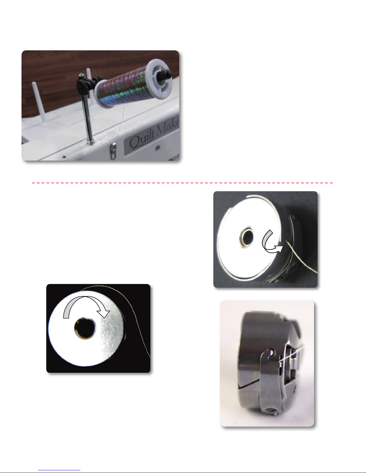
Optional Horizontal Spool Pin
Figure 16
Bobbin and Thread Tension
1. An optional horizontal spool pin is available for
metallic and specialty threads wound on a spool (not
a cone).
2. The horizontal spool pin mounts on the laser stylus
guide post on the top of the machine
(see Figure 16).
3. When using threads on the Horizontal Spool Holder,
skip thread guide A. Thread the top hole only of the
three-hole thread guide B, back to front.
4. Continue threading the machine as described in steps
3 through 7 on page 16.
Adjustments
Inserting the Bobbin
Note: Turn off the power switch while inserting the
bobbin case or anytime your hands are near the needle
area.
1. Place the bobbin in the bobbin case so that the
thread pulls off clockwise when viewing the open side
(Figure 17).
Figure 17
Figure 18
2. Slide the thread through the slot (Figure 18) and
under the tension spring leaving 5 to 6 inches of
thread hanging loose (Figure 19).
janome.com
TENSION
SPRING
Figure 19
Page 17
Page 18

Bobbin and Thread Tension Adjustments...cnt’d
3. Turn off the power switch while inserting the bobbin
case or anytime the hands are near the needle area.
4. Do not lift the lever on bobbin case. When placing the
machine fit the bobbin case onto the hook spindle in
the machine. Rotate the casing until the open throat
keys into the alignment notch in the middle of the
hook. Push the casing in until it stops in place. Push
inward until it clicks (see Figure 20).
Note: It is not suggested that the lever on the bobbin
case be used for this installation. The latch lever should
be used only for removal of the bobbin case.
Bobbin Tension
The bobbin tension is the foundation tension for the
entire machine. To test that bobbin tension is correct,
hold the bobbin case in the palm of your hand with the
open end facing up. Wrap the thread around your index
finger and while pulling up on the thread and gently
wiggling the finger front to back (not up and down
which is not consistent), the bobbin case should lift up
on its side, but NOT lift out of your hand. If it will not
lift up onto its side, it is too loose and if it lifts out of
your hand, it is too tight. The small screw in the center
of the tension spring is where the adjustment is made
(see Figure 21). Turn clockwise to tighten and counterclockwise to loosen the bobbin case tension. Check your
bobbin tension every time a new bobbin is inserted.
Note: Bobbin tension adjustment is a minute turn of the
screw like the ticking of a clock.
Figure 20
Drawing the Bobbin Thread to the Top of
the Quilt
1. After the machine is threaded, locate needle up/down
button on the left handle.
2. While firmly holding the tail of the needle thread
with the left hand, press the needle up/down button
with right hand, bringing the needle back to the up
position.
3. Pull the machine three to four inches away while
holding the needle thread.
4. Bobbin thread will pull up and through to the top,
allowing you to grasp the loop and pull it to the
desired length.
Figure 21
Page 18
Quilt Maker Pro 18 User Manual
201704
Page 19

Easy-Set Tension™ Adjustment
IMPORTANT: Top tension should be adjusted only after
the bobbin case foundation tension adjustment is made.
Puckering, gathers and thread breakage occur when the
top tension is too tight. Loops and thread nests occur
on the back when the top thread tension is too loose.
Tension may need to be adjusted depending on the
fabric, thread or batting you are using on each project.
It is easy to set the top tension with the Janome Quilt
Maker Pro 18 Easy-Set Tension. To adjust the top tension
tighter, turn the tension knob clockwise. To loosen the
tension, turn the tension knob counterclockwise. Unlike
the bobbin-case adjustment, which requires minute
adjustments (like the tick of a clock), the top tension
knob might need to be turned anywhere from 1/4 of a
turn to two to four turns to achieve balanced tension.
Maintenance
Cleaning and Lubricating the Machine
Only use light sewing machine oil in the Janome Quilt
Maker Pro 18. Internal oiling is not necessary on the
Janome Quilt Maker Pro 18 except when the machine is
taken to a service technician for routine maintenance
and cleaning. The hook assembly, however, needs
regular lubricating. Failure to keep the hook assembly
lubricated can cause severe damage to the machine.
As you adjust the tension, a tension value appears on
the Main Screen (when the machine is turned on). make
a note of this value to easily set the tension again in the
future for the same type of thread.
Note: Before adjusting the top tension, remember to
floss or pull the top thread up into the tension discs or
it will float outside the discs providing little or no top
tension. This could cause significant tension or nesting
problems on the bottom side of the quilt.
To lubricate, turn off the machine. Remove bobbin and
case before oiling. Clean around the hook assembly
with a soft brush to remove lint. Put a very small drop of
oil on the hook in the region where the bobbin basket
assembly and the rotating hook meet (see Figure 22).
The bobbin basket is the portion of the hook that the
bobbin case snaps into. The bobbin basket remains
stationary while the hook rotates around the basket. The
oil lubricates the region where these two components
interlock. A drop of oil in the region indicated will work
its way back into the interlocking area of the hook and
bobbin basket.
The frequency of lubrication depends upon the usage
of the machine. Lubricating is recommended before
running the machine if it has not been used regularly,
or every other bobbin change if used frequently. After
oiling, always sew a scrap piece as oil may cling to
thread. Over oiling can cause excess dripping from the
bobbin assembly. Lack of lubricant may be noticed by a
change in the sound of the machine and will affect stitch
quality.
Figure 22
Cleaning the Touchscreen
Never use any chemicals to clean your display as this
may adversely affect the touch screen response. Use a
soft rag dampened with isopropyl alcohol and gently
wipe the display to remove any marks.
janome.com
Page 19
Page 20

Using the Touch Screen Displays on the Handlebars
Machine and Handlebar Menus
The Janome Quilt Maker Pro 18 has touch-screen
displays on the front and rear handlebars. Settings may
be changed at either of these locations.
Main Screen
Manual Mode Screen
Button Functions:
Pressing the “Regulated” button while in the Manual
Mode Screen will toggle to the Regulated Mode Screen.
The current stitching mode is highlighted in blue when
activated. Different options are available depending
upon which mode the system is in. (Figure 23)
Needle Stop
Figure 23
The Needle Stop setting enables you to specify whether
you want the needle to end in the up or down position
when you stop quilting (Figure 24). If you select Down,
when you press the stop button on the right handlebar,
the needle ends in the down position. If you select Up,
the needle ends in the up position when you press the
stop button on the right handlebar. Switch between
the up and down position by pressing the Needle Stop
button.
Figure 24
Figure 25
Easy-Set Tension
The tension box (Figure 25) on the Main Screen shows
the current tension setting as a numeric value. As you
turn the tension dial clockwise to tighten the top tension,
the number increases in increments of five. As you turn
the tension dial counterclockwise to loosen the top
tension, the number decreases in increments of five. The
faster you turn the dial, the faster the numbers increase
or decrease.
After setting the bobbin tension, test the top tension
by stitching on a fabric scrap on the edge of the quilt
batting and backing. Increase or decrease as needed
until you have achieved balanced tension. Make a note
of the type of thread (weight, brand, color) you’re using
and the tension value. You will be able to quickly and
easily set the tension when you use this same thread
again in the future.
Page 20
Quilt Maker Pro 18 User Manual
201704
Page 21

Figure 26
Figure 27
Figure 28
Bobbin Thread Indicator
If you use the Low-Bobbin Estimator feature, The Bobbin
Thread Indicator box (Figure 26) shows how much
bobbin thread remains on the bobbin. The value counts
down until it gets to zero, at which time the low-bobbin
alarm alerts you that it is time to put in a new bobbin if
the alarm is enabled. While the machine is recording how
much thread is on a bobbin, REC appears on the screen
to remind you that it is estimating the bobbin capacity.
Speed
Pressing the Limit “+” will increase the manual mode
motor speed and pressing the Limit “–” button will
decrease the manual mode motor speed. This has the
same effect as pressing the “+” and “-” buttons on the
actual handles. The speed range is between 5% and
100%, or between 90 and 2,200 stitches per minute
(SPM). The percent speed is displayed in the white box
at the top of the screen. (Figure 27)
Manual Presets
Save up to three manual-mode preset speeds to quickly
switch between speed preferences. For example, you
may prefer a slower speed when using rulers and a faster
speed when doing all-over meandering quilting. Use the
“+” and “-” buttons to adjust the speed percentage and
then press one of the record buttons next to the preset
value to store that speed as a preset. When you want to
use one of the preset speeds, simply press the speed.
(Figure 27)
On/Off Indicator
The circle in the center of the top bar turns green when
you press the “Start” button on the handles to indicate
the needle is in motion. When you press “Stop,” the
circle will turn red. (Figure 28)
Figure 29
janome.com
Regulated Mode Screen Button Functions
Stitches Per Inch (SPI)
Pressing the “+” or “-” buttons near the top right portion
of the screen will increase or decrease the stitches per
inch (SPI) setting. The setting is reflected in the white
indicator box at the top right portion of the screen. This
value can be adjusted between 4 and 18 stitches per
inch. (Figure 29)
Page 21
Page 22

Basting Stitches
There are four basting stitch settings controlled by
the stitches per inch function. After the SPI reaches its
lowest stitch setting of 4 stitches per inch, pressing the
“-” button will activate the basting settings:
• 0.5-inch (one stitch every half-inch movement of
the machine)
• 1-inch (one stitch every one inch movement of the
machine)
• 2-inch (one stitch every two inches of movement of
the machine)
• 4-inch (one stitch every four inches of movement
of the machine)
Figure 30
Figure 31
After selecting the basting stitch setting, begin quilting
by pressing the Start button. As you move the machine
across the quilt, it will perform a stitch (needle down and
then needle up) every half inch, one inch, two inches, or
four inches according to your choice. The basting stitch
options are available in stitch regulation mode: Cruise
and Precision. (Figure 30)
Stitch Regulation Style (SR)
The “SR Style” box in the lower right-hand corner of the
screen indicates whether the machine is in “Precision”
regulation mode or in “Cruise” regulation mode. (Figure
30)
Precision
If “Precision” mode is selected, the Janome
Quilt Maker
Pro 18 will not start stitching until you begin pushing the
machine. (Figure 31)
Page 22
Quilt Maker Pro 18 User Manual
201704
Page 23

Cruise
If “Cruise” mode is selected, when you press “Start” on
the handles the machine will immediately begin stitching
at the percent speed indicated below the “Cruise”
button. The “Cruise” speed is the minimum speed the
machine will stitch, regardless of how slow you are
pushing the machine. This means that when you slow
down to a stop, the needle will continue stitching at the
set cruise speed until you begin moving the machine
faster than what the cruise speed is set to or you press
the “Stop” button on the handles. The “Cruise” speed
can be adjusted using the “+” and “-” buttons that
appear below the “Cruise” button when “Cruise” mode
is selected. “Cruise” speed can be adjusted between 3%
and 50%. (Figure 32)
Figure 32
Figure 33
The start indicator box (Figure 33), which is the box at
the top center of the screen, will change from red to
green as soon as you press the “Start” button on the
handles. If you are in “Precision” mode, the needle will
not start moving until you start moving the machine, so
this green indicator shows that the “Start” command was
accepted and the machine is ready to begin stitching.
In “Cruise” mode, the red box will turn to green and
the needle will begin stitching immediately at the set
“Cruise” speed.
On/Off Indicator
If the machine does not sense that it has been moved
in any direction after it has been started, it will
automatically stop regulation mode and the start
indicator box will turn red. When in “Precision” mode,
this happens when no movement of the machine has
been detected for two minutes. A system message will
appear on the screen to warn the user the machine
has stopped. This box is cleared by pressing the “OK”
button. In “Cruise” mode, the machine will stop stitching
after about three seconds if no movement has occurred.
Tools Menu
The Tools screen provides access to other functions
available on the Janome Quilt Maker Pro 18 (Figure 34).
Figure 34
janome.com
Page 23
Page 24

Low Bobbin
The Janome Quilt Maker Pro 18 includes a low bobbin
capability so you can estimate how soon your bobbin
thread will run out. This Low Bobbin Capacity is based
on an estimate of how much of a particular thread can fit
on a bobbin, in combination with other quilting factors
such as tension, stitches per inch, and how much bobbin
thread you pull up when beginning and ending your
quilting (Figure 35 and 36).
To estimate how much thread is on a bobbin, place a full
bobbin in the machine and under the heading Bobbin
Thread Capacity, press the Record button (Figure 36),
quilt as usual.
Figure 35
Figure 36
When the bobbin runs out, press the square Stop
Recording button and note the number that is indicated
under the Bobbin Thread Capacity (Figure 36), perhaps
210. Since you want a warning as to when the bobbin
is getting low, use the “-” button to specify a lower
number, such as 195. Save that as one of the Bobbin
Thread Capacity Presets. You might want to make a note
as to which type of thread the preset represents. Put a
new bobbin with the same thread into the machine and
press the New Bobbin button. Then press the Alarm
button. As you quilt, the remaining bobbin thread value
will estimate how much thread remains on the current
bobbin, and when you reach the capacity value, an alarm
will sound warning you that your bobbin is nearly out of
thread (Figure 37).
When operating in Manual mode, the low bobbin
function assumes you will stitch at approximately the
last SPI setting you had on the regulated screen. If the
SPI setting was below 8 stitches per inch, the function
will assume you will quilt at 10 stitches per inch. It is
advisable therefore to set the stitches per inch that
you will be quilting on the regulated screen before you
change to manual mode.
Figure 37
Page 24
You can store three Bobbin Thread Capacity preset
values – one for each of three different types of thread.
Simply go through the record process with a full bobbin
of that type of thread and then store the capacity as a
preset. When you switch to using that type of thread,
press appropriate preset button. Insert a full bobbin with
that type of thread, press New Bobbin, then press the
Alarm button and all of the settings will be based on that
type of thread.
Quilt Maker Pro 18 User Manual
201704
Page 25

Figure 38
Timers
There are two useful timers. The first (top) timer is a
reminder timer. It enables you to set an alarm to go off
after a specific period of time, similar to a kitchen timer.
Use the “+” and “-” buttons to set the time duration.
Then press the “play” button to activate the timer. When
the time duration has elapsed, an alarm will sound and a
message appears on the display (Figure 38).
The second (bottom) timer enables you to track how
much time you spend on a quilt project. When you begin
a new project, press the Reset button. Then press the
“play” button to begin recording your quilting time. The
timer records when the machine is quilting. The time is
saved even when the machine is turned off. When you
begin another quilting session, quilting time is added to
the timer. Only press Reset when you want to zero-out
the timer and begin a new timing session.
Sound Screen
The “Volume” portion of this screen has two buttons and
a sliding control. Pressing on the “Mute” button turns the
alarm volume off. Pressing the “Max” button turns the
volume to its loudest level. Pressing the sliding control in
any position sets the volume to the level indicated in that
control. Pressing and moving back and forth across the
sliding control will change the volume up as it is moved
left to right and down as it is moved from right to the
left. The Over-Speed Alarm box allows the user to turn
the alarm on and off. (Figure 39)
Figure 39
Figure 40
Press the “Main” button to return to the “Regulated” or
“Manual” menu screen or the “Back” button to return to
the “More” menu screen.
Calculator
A basic calculator is provided. (Figure 40)
Press the “Main” button to return to the “Regulated” or
“Manual” menu screen or the “Back” button to return to
the “More” menu screen.
janome.com
Page 25
Page 26

Figure 41
Lights
The Janome Quilt Maker Pro 18 comes equipped with a
light ring around the needle bar, two high intensity LED
modules on each side of the display. These lights are
directed towards the quilting area. (Figure 41)
Turn lights on or off by touching the light bulb icons. Use
the slider to adjust the light brightness from low to high.
(Figure 42)
Figure 42
Page 26
Quilt Maker Pro 18 User Manual
201704
Page 27

System Information
Information contained in the white ovals identify the
electronics board revision numbers as well as the
firmware revision numbers of the Janome Quilt Maker
Pro 18 and its handlebars. The Lifetime and Trip (or
project) stitch counters count the number of stitches
the machine has performed. The Lifetime count is the
total number of stitches made since the machine was
built. The Trip Counter can be reset to keep track of the
number of stitches made during a given project. To reset
this counter, press the blue “Reset” button just to the left
of the “Trip” box. The Lifetime counter cannot be reset
and should be used as an indicator to determine when
general machine maintenance should be performed by
an authorized Janome Representative. (Figure 43)
Figure 43
Press the “Main” button to return to the “Regulated” or
“Manual” menu screen or the “Back” button to return to
the “More” menu screen.
Set Language
The Janome
Quilt Maker Pro 18 screens can appear
in English, French, German, or Spanish. On the More
Screen, press the lower-left button to cycle between
English, Français, Deutsch, and Español. After selecting
your preferred language, press Main to return to the
Main Screen.
Press the “Main” button to return to the “Regulated” or
“Manual” menu screen or the “Back” button to return to
the “More” menu screen.
Diagnostics Screen
Seven different diagnostics tests can be performed on
the machine. These functions test the motion encoders,
the motor control functions, the key switches and the
internal position sensors. (Figure 44)
Figure 4 4
janome.com
Press the “Main” button to return to the “Regulated” or
“Manual” menu screen or the “Back” button to return to
the “More” menu screen.
Page 27
Page 28

Figure 45
Diagnostics Tests
Motor Sensor Test
The “Motor” Sensor test can help you determine whether
there may be a problem with the Janome Quilt Maker
Pro 18 motor. Slowly rotating the handwheel should
result in a pulsing audible “beep.” If you get a constant
solid “beep” or no “beep” at all, this indicates a failed
test and the machine should be inspected by a qualified
Janome repair technician. (Figure 45)
Press the “Main” button to return to the “Regulated” or
“Manual” menu screen or the “Back” button to return to
the “More” menu screen.
Needle Sensor Test
The Needle Sensor test will indicate whether the needle
position sensor is functioning properly. Rotating the
handwheel should result in a “beep” for half of a stitch
cycle followed by no “beep” for the other half. (Figure 46)
If you hear a constant beep or no beep at all for a full
360° rotation of the handwheel, this indicates a failed
test and the machine should be inspected by a qualified
Janome repair technician.
Figure 46
Figure 47
Press the “Main” button to return to the “Regulated” or
“Manual” menu screen or the “Back” button to return to
the “More” menu screen.
X Motion Sensor Test
Use the X Motion Sensor test to verify functionality of
the “X” stitch regulator encoder (the encoder mounted
at the rear of the carriage). As you slowly move the
carriage left and right you should hear a pulsing “beep”
that pulses faster as you move faster. A solid beep, no
beep, or periods of irregular beeping (with constant
motion) indicate a problem with the “X” encoder. The
most likely cause of a problem is a stitch regulator wheel
that is not making consistent contact with the track.
Check the spring tension on the sensor assembly on the
carriage to assure that it will easily return to the fully
extended position after being compressed. Also assure
that the track is straight with no dips or indentations and
that it is clean and free of contamination. Other causes
are an unplugged or damaged cable or possibly an issue
with the main control board. (Figure 47)
Press the “Main” button to return to the “Regulated” or
“Manual” menu screen or the “Back” button to return to
the “More” menu screen.
Page 28
Quilt Maker Pro 18 User Manual
201704
Page 29

Motor Speed Sensor Test
The “Speed” Sensor test can help you determine whether
or not there is a problem with the Janome Quilt Maker Pro
18 speed sensor. Before performing this test, remove the
bobbin case and the top thread. Press the “Start” button
and the machine will begin slowly rotating. The white box
will show a number that should stabilize at 100 if the sensor
is functioning properly. Pressing “Start” again will stop the
machine. (Figure 48)
Press the “Main” button to return to the “Regulated” or
“Manual” menu screen or the “Back” button to return to the
“More” menu screen.
Figure 48
Figure 49
Y Motion Sensor Test
Use the Y Motion Sensor test to verify functionality of the
“Y” stitch regulator encoder (the encoder mounted to the
rear power pod side machine wheel). As you slowly move
the carriage toward and away from you, you should hear
a pulsing “beep” that pulses faster as you move faster. A
solid beep, no beep, or periods of irregular beeping (with
constant motion) indicate a problem with the “Y” encoder.
The most likely cause of a problem is a stitch regulator
wheel that is not making consistent contact with the track.
Check the spring tension on the sensor assembly on the
machine to assure that it will easily return to the fully
extended (down) position after being compressed. Also
assure that the track is straight with no dips or indentations
and that it is clean and free of contamination. Other causes
are an unplugged or damaged cable or possibly an issue
with the main control board. (Figure 49)
Press the “Main” button to return to the “Regulated” or
“Manual” menu screen or the “Back” button to return to the
“More” menu screen.
Figure 50
janome.com
Keyp a d Tes t
The Keypad test allows the user to press any of the
four keys on the front or back handles to verify that the
Janome
18
Quilt Maker Pro 18 is reading the buttons as they
are pressed. When a key is pressed the name of the key
that is pressed will appear in the white box. When it is
released, the name will disappear. Perform this test on the
rear display for the rear keys, and the front display for the
front keys. (Figure 50)
Press the “Main” button to return to the “Regulated” or
“Manual” menu screen or the “Back” button to return to the
“More” menu screen.
Page 29
Page 30

Figure 51
Calibrate Tension
The Tension button enables you to calibrate the tension
device (Figure 51). You should only calibrate the tension
device under the direction of Janome technical support.
While calibrating the tension, you will be asked to do the
following:
1. Remove the tension knob.
2. Gently press the spring against the tension discs while
not compressing the spring.
3. While holding the spring in place, press Reset.
4. When calibration is complete, replace the tension
knob.
Page 30
Quilt Maker Pro 18 User Manual
201704
Page 31

Janome STITCH REGULATOR OPERATION
Choose from Two Types of Stitch Regulation: Cruise or Precision
In regulation mode the status box at the top left of the
screen should say “Regulated”. If it says “Manual”, simply
press the “Regulated” button on the touch screen to
switch from “Manual” mode to “Regulated” mode.
IMPORTANT NOTES ABOUT TURNING STITCHREGULATION ON OR OFF
You can stop the machine at any time by pushing either
the “Start/Stop” or the “Needle Up/Down” key on the
handles. In Cruise Regulation mode, if you don’t move
the machine after 3 or 4 seconds, the machine will stop
and position the needle. In Precision Regulation mode,
the needle pauses when you stop moving the machine
and will begin stitching again when you start moving the
machine. Press the “Start/Stop” (or “Needle Up/Down”)
key in Precision Regulation mode to stop the needle
completely and cause the needle to position itself in the
Needle Up or Down position.
Cruise Regulation Mode
When in Cruise Regulation mode, the start indicator box
in the top center of the “Regulated” screen is red. When
you press the “Start/Stop” key to start the machine,
the indicator will turn green AND the needle will begin
moving up and down.
Precision Regulation Mode
When in Precision Regulation mode, the start indicator
box in the top center of the “Regulated” screen is
red. When you press the “Start/Stop” key to start the
machine, the indicator will turn green. As you start
moving the machine, it will begin stitching. When you
stop moving the machine, the needle pauses (sometimes
in mid-stroke.)
When you press the “Start/Stop” (or “Needle Up/Down”)
key to stop the machine, the indicator will turn red,
showing that the needle will not move when you move
the machine.
Always make sure the indicator is RED when you are in
Precision Regulation mode prior to working with your
hands near the needle (changing the needle, replacing
the bobbin, etc.) to avoid unwanted stitching in your
quilt or your hands!
If you leave the Janome Quilt Maker Pro 18 in Precision
Regulation mode with the start indicator box green and
do not move the machine for two minutes, the system
will “time-out” and a message box will appear. This
indicates that the system has stopped and you will need
to press the “Start” button again to resume quilting.
The minimum speed of the needle is dependent upon
the setting you choose (from 3% to 50%). Janome
recommends beginning with a setting of 3%.
When to Use Cruise Regulation Mode
The constant minimum stitching speed featured in the
Cruise Regulation mode is used for precise placement
of stitching when backtracking (such as along the tops
of feathers) or when creating sharp points (such as the
point of a star or the bottom of a heart).
When to Use Precision Regulation Mode
Precision Regulation mode is especially useful for ruler
work. Stitch along the length of the ruler for the span
of your hand and stop. When you stop moving the
machine, the needle pauses. Do not turn off the machine.
Move the ruler and commence quilting. The Precision
Regulation helps you avoid “bobbles” and uneven
stitches.
Quilting Speed While in Stitch-Regulation Mode
It is important not to move the machine too fast, since
this will result in an OVERSPEED CONDITION, during
which, the machine cannot maintain stitch regulation
until you slow your motions to an appropriate speed.
The Overspeed Alarm will alert you to this condition,
giving you the signal to slow down. Stitch regulation is
not a license to move the machine as fast as you can. Its
purpose is to maintain even stitches while quilting at an
appropriate speed.
You can return to manual mode by pushing the “Manual”
button below the “Regulated” button on the touch
screen display.
janome.com
Page 31
Page 32

Getting Started Quilting
Thread Requirements
Threads have a tendency to dry rot over a period
of time. Be sure to choose high quality threads for
your valuable heirloom quilts. Most machine quilting
threads on the market today are acceptable.
Needle Requirements
For general quilting, a size 16/100 needle will
accommodate most threads and fabrics.
Heavier threads, such as top stitch and some
decorative threads, require a larger needle such as
18/110 or 20/120. Lofty batts and heavier fabrics such
as denim, canvas or densely woven fabric may also
require a larger needle.
To Prepare for Quilting
With any quilting machine, it is important to
understand the basics of free motion quilting. The
Janome Quilt Maker Pro 18 does not have feed dogs
like domestic machines; therefore, the fabric does
not automatically feed under the hopping foot. The
operator should synchronize the speed as well as the
movement of the machine to get an even, consistent
stitch.
pressing the “Start/Stop” key on the front or rear handle
bars to begin quilting make certain to begin moving
the machine immediately. If the needle stitches in one
place too long, the stitches build up on top of each
other causing a build-up of thread or thread breakage.
When bringing the machine to a complete stop press
the “Start/Stop” key at the same moment the machine
stops moving. If the machine is still moving when the
“Start/Stop” key is pressed, it can cause deflection in the
needle, possibly causing it to bend or break.
In PRECISION REGULATION mode, the needle will not
begin moving when you press the “Start/Stop” key until
you begin moving the machine.
When quilting, relax your hands and maintain a light
touch on the handlebars. Gripping the handlebars too
tightly may cause body tension resulting in poor quilting
quality. The Janome
the Quilt Maker Pro 18 Frame system will give you a
smooth even glide.
18
Quilt Maker Pro 18, combined with
In order to become comfortable with the free motion
of the Janome Quilt Maker Pro 18, users can begin
with a few “beginner” techniques.
In Manual Mode: Set the machine at a medium speed
and begin moving it until you become accustomed
to the resistance. By moving the machine faster,
the stitches begin to elongate. The stitch speed can
either be increased or the machine can be moved
slower to get the stitches back to the desired
length. By moving the machine slower, the stitches
get shorter and can build up on top of each other,
breaking the thread or making it extremely difficult
to unpick. The stitch speed can be decreased, while
maintaining a constant motion with the machine to
bring the stitches back to the desired length.
In Stitch Regulator Mode: Set the machine to desired
stitch length. Begin moving the machine to become
accustomed to the resistance. The machine motor
will slow down or speed up to maintain a consistent
stitch length according to how quickly or slowly you
move the machine. Moving the machine too fast or
in radical or jerky movements will defeat the stitch
regulator function.
In MANUAL or CRUISE REGULATION mode, when
Page 32
Quilt Maker Pro 18 User Manual
201704
Page 33

Troubleshooting
You can correct many problems on your own. If you need additional help, contact your local, authorized Janome
retailer. You can also contact Janome Monday through Friday 8:30AM - 5:00PM EST, 1-800-631-0183 option 3 .
First check the following:
The AC power cord is properly connected and the power switch is turned on.
Confirm that all cables are properly seated into their connections.
Turn off the machine completely. Wait for at least ten seconds and then turn it back on.
If the above checks did not solve the problem, refer to the information below.
Skipped Stitches Corrective Measure(s)
The needle is damaged, dull, bent,
or installed improperly
• Replace the needle regularly, at least once per quilt. Use only the
recommended needle system.
• Always change the needle if the needle has struck any hard object such
as a straight pin, etc. The tip of the needle can become damaged or
burred, resulting in fabric damage as well as skipped stitches, thread
breakage, or shredding.
• Always change the needle if it has been hit, bumped or pulled off center
while maneuvering the machine about the quilt. A slightly bent needle
can be a major cause of skipped stitches.
Incorrect needle size • Use the proper size of needle for the work and thread being used.
Some battings and fabrics used in quilting may constrict or impede the
thread passing through the front groove of the needle. This diminishes
the loop lift required for stitch formation. Typically, a larger needle
will solve the problem. However, using certain smaller sizes of needles
and ball pointed needles solve some specific problems. You will need
to experiment to determine which work best with your combination of
fabric, thread, and batting.
Fabric is too tight on the frame • Loosen the pole tension on the frame. Fabric that is rolled too tightly
causes the fibers to separate and the fabric to bounce while quilting.
This reduces the needle friction on the thread, resulting in a smaller
thread loop or skipped stitches.
Thread tension too tight • Check bobbin case tension and then check top thread tension. (For
more information about adjusting tension, see Bobbin and Bobbin
Tension and Top Thread Tension in the Using Your Machine section of
this manual.)
janome.com
Page 33
Page 34

Troubleshooting
The needle is not positioned
properly
Improper threading • Ensure that the machine is threaded correctly.
The Needle Breaks Corrective Measure(s)
The needle is bent or not installed
properly
• Position the needle properly to the needle bar. Inspect the position of
the needle to make sure the needle is at the 6 o’clock position. When
you stand directly in front of the needle (facing the bobbin case side
of the machine), you will see the entire needle eye directly facing you.
This is 6 o’clock position.
• Make sure (a) the needle is installed all the way into the needle bar to
the needle-stop hole in the needle bar, (b) the long groove in the needle
is toward the front (bobbin case side), and (c) the scarf (scooped out
part of the back of the needle) is toward the back of the machine.
• The needle can sometimes be rotated to 5 o’clock (slightly right) or 7
o’clock (slightly left) to adjust for a more positive thread loop pickup by
the hook point.
• Replace the needle. Make sure that the needle is pushed into the needle
bar clamp until it can go no farther. Visually check that it is up to the
top of the stop/sight hole above the needle bar clamp screw. If the
needle isn’t installed properly, it can cause damage in the bobbin area
and needle plate.
The needle hits the needle plate • Correctly position the needle, needle plate, or hopping foot. Replace
with a new needle.
Stitches are Puckered Corrective Measure(s)
The tension is not balanced.
Top and bottom tension are both
too tight.
Needle too large for quilting fabric • Replace the needle with a size better suited for the fabric.
Poor Stitch Quality Corrective Measure(s)
The tension is not balanced • Balance the tension of the needle thread after ensuring the bobbin
Bobbin case is damaged,
corroded, dirty, etc.
Loose Display Housing Corrective Measure(s)
Loose display housing Loosen handle bar clamp bolts, rotate handlebars to desired position and
• Balance the tension of the needle thread after ensuring the bobbin
tension is adjusted correctly. (For more information about adjusting
tension, see Bobbin and Bobbin Tension and Top Thread Tension in the
Using Your Machine section of this manual.)
tension is adjusted correctly. (For more information about adjusting
tension, see Bobbin and Bobbin Tension and Top Thread Tension in the
Using Your Machine section of this manual.)
• Since thread slides over the surface of the bobbin case at a high speed,
make sure the case is free of any lint or foreign matter that could
impede thread passage through the machine.
push together, tighten clamp bolts.
Page 34
Quilt Maker Pro 18 User Manual
201704
Page 35

Troubleshooting
Moving the machine too fast
for needle speed selected
(Manual mode)
Tension is Poor Corrective Measure(s)
Lint caught under the tension
spring in the bobbin
Hand Wheel Won’t Rotate Corrective Measure(s)
Thread is entangled and caught in
the hook
Thread Nests Under Quilt Corrective Measure(s)
Not enough tension on
top thread
• Synchronize machine movement and needle speed to get roughly 8 to
10 stitches per inch. Elongated stitches are an indication of moving the
machine too fast for the current speed.
• If using short staple threads, inexpensive, or industrial threads, or
coated threads, lint and other material will build up under the tension
spring and begin to lift the spring, reducing the spring’s ability to
compress against the thread. Insert a needle or business card under the
spring and clear out the lint. The bobbin tension will return fairly close
to its preset tension. Test the tension before quilting.
• Turn off the machine and unplug the machine from the electrical outlet.
Lubricate the hook, strongly turn the hand wheel clockwise and if
necessary counterclockwise several times, and then remove the thread
caught in the hook.
• Check that the machine is threaded correctly. Make certain that the
thread is flossed snugly in place between the two tension discs. If
the machine is threaded correctly, tighten top tension by rotating the
tension knob clockwise. (For more information about adjusting tension,
see Bobbin and Bobbin Tension and Top Thread Tension in the Using
Your Machine section of this manual.)
Improper threading
Hard to Guide Machine Corrective Measure(s)
Carriage wheels not centered
on track
Thread caught in wheels • Remove all thread or debris in wheels. Check that the tracks are free of
Motor Fails to Run Corrective Measure(s)
On/Off switch turned off
Machine not receiving power • Check that the power connector is securely plugged into the back of
* If the troubleshooting above does not eliminate the problem, please consult an authorized Janome Quilt Maker
Pro 18 representative.
• Refer to threading diagram and threading instructions.
• Center the carriage wheels on top of the continuous track. Check that
the machine carriage has not jumped the track.
lint and threads.
• Turn the machine on by using the switch on the back power pod.
the machine and the three-prong end is plugged into the power source.
janome.com
Page 35
Page 36

Troubleshooting
Uneven Quilt Design Corrective Measure(s)
Take-up rollers may be bowed
or bent
Leaders are stretched or worn • If fabric is beginning to stretch or fray, contact Janome to purchase
Thread Breaks Corrective Measure(s)
Thread is poor quality or
may have severe twisting or
thread rot
• Make certain the fabric is not rolled too tight, causing the poles to bow.
Check that poles are inserted completely together with the push pins
engaged so bowing won’t occur.
replacement leaders. Do not wash the leaders.
• Look for severe twisting of threads when approximately 12 to 15 inches
has been pulled off, with the ends pinched together. Cotton threads are
particularly susceptible to dry rot or wet rot which makes thread brittle.
Do not use poor quality thread, or thread that is rotted or brittle.
Top and bobbin tensions
not balanced
The machine head has been
threaded incorrectly or thread
spools are not positioned correctly
Debris in tension discs
Bobbin rotation is not smooth • Change the bobbin. The slightest hesitation of the bobbin rotation can
Needle is burred, bent or dull, or
installed incorrectly
• Balance the tension of the needle thread after ensuring the bobbin
tension is adjusted correctly. (For more information about adjusting
tension, see Bobbin and Bobbin Tension and Top Thread Tension in the
Using Your Machine section of this manual.)
• Check that the machine is threaded correctly.
• Inspect for accidental double wrapping of thread on thread guides.
• Inspect the thread mast, making sure the eyelets of the mast are
directly over the spools.
• Inspect the vertical positioning of the thread cones. Tipped cones can
dramatically affect thread tension and can cause breakage.
• Inspect for particles and remove any fuzz or debris.
be the cause of dramatic tension change and
thread breakage.
• Change the needle at least once per quilt. Make sure the needle is
installed to the top of the stop hole in the needle bar.
Needle not suitable for thread • Replace the needle to one better suited for the thread. Use the proper
Hesitating too long at one point in
quilting motif
Page 36
size needle.
• Move more quickly so stitches don’t overlap or build up. When starting
the machine, begin moving immediately. Sewing in one place too long
will cause the thread to break.
Quilt Maker Pro 18 User Manual
201704
Page 37

Troubleshooting
Improper needle/hook relationship • Machine timing needs to be checked. Consult an authorized Janome
technician.
Damage or burr at needle hole
of needle plate or other thread
handling part
Wrong type of needle • Use only the needles recommended by Janome: 134 (135x7) sizes 12
Other possible problems • Needle too close to hook, causing friction and possible collision of hook
Nothing visible on the display Corrective Measure(s)
Display cables unplugged • Locate the black cables that plug into the touch-screen display and
• If thread is shredding at the needle plate, check for burrs or jagged
edges. Gently rub with metal cloth to remove the sharp edge. Consult a
repair technician to polish any hard-to-reach or delicate areas, or if the
burr is inside the throat.
through 20.
point and needle (causing broken thread).
• Needle plate damage
• Hook damage
• Broken needles or damaged needle bar clamp
connect to the side of the machine. Make sure both ends are plugged
in securely.
NOTE: If the troubleshooting tips do not eliminate the problem, please consult an authorized Janome Quilt Maker
Pro 18 representative.
janome.com
Page 37
Page 38

Page 38
Quilt Maker Pro 18 User Manual
201704
Page 39

BOBBIN WINDER
USER MANUAL
Revision 2.0, Part number 001QMPROBW
Page 40

Bobbin Winder: Table of Contents
Important information ............................................................................39
General Safety Considerations ....................................................................40
Environmental Considerations .....................................................................40
Bobbin Winder Components ......................................................................41
Assembly Instructions ............................................................................42
Bobbin Winder Controls ..........................................................................44
Using the Bobbin Winder .........................................................................44
Adjusting the Bobbin Sensor Assembly.............................................................46
Adjusting the Thread Tension .....................................................................47
Thread Tracking Adjustment ......................................................................47
Troubleshooting the Bobbin Winder ...............................................................48
Page 40
Quilt Maker Pro 18 User Manual
201704
Page 41

Important Information
Regulatory Information
This equipment has been tested and found to comply
with the limits for a Class B digital device, pursuant
to part 15 of the FCC Rules. These limits are designed
to provide reasonable protection against harmful
interference in a residential installation. This equipment
generates, uses, and can radiate radio frequency energy
and, if not installed and used in accordance with the
instructions, may cause harmful interference to radio
communications. However, there is no guarantee that
interference will not occur in a particular installation.
If this equipment does cause harmful interference to
radio or television reception, which can be determined
by turning the equipment off and on, the user is
encouraged to try to correct the interference by one or
more of the following measures:
— Reorient or relocate the receiving antenna.
— Increase the separation between the equipment and
Re ce iver.
— Connect the equipment into an outlet on a circuit
different from that to which the Receiver is
connected.
— Consult the dealer or an experienced radio/TV
technician for help.
This Class B digital apparatus complies with Part 15 of
the U.S. Federal Communications Commission (FCC)
rules, Canadian ICES-003 and RSS-210. Operation is
subject to the following two conditions: (1) this device
may not cause interference, and (2) this device must
accept any interference received, including interference
that may cause undesired operation.
Réglementations
Cet appareil numérique de la classe B est conforme
aux norms NMB-003 et CNR-210 du Canada. Son
fonctionnement est assujetti aux deux conditions
suivantes: (1) Cet appareil ne puet pas provoquer
d’interférences nuisibiles et (2) cet appareil doit accepter
toute interference recue, y compris les interferences
pouvant entraîner un fonctionnement non desire.
Specifications
Bobbin Winder
Input Power - 12Vdc at 2.5 A maximum
Variable speed winding
3600 rpm maximum winding speed
Auto-shut off sensor
Auto-shut off after 5 minutes
Bobbin winder power supply
Input: 100 – 240VAC 50/60Hz 50VA
Output: 12Vdc at 3A
janome.com
Page 41
Page 42

General Safety Considerations
Environmental Considerations
WARNING
To protect against risk of fire, bodily injury, electrical
shock or damage to the product:
• Do not immerse any part of this product in water or
other liquid.
• Do not spray liquid on this product or allow excess
liquid to drip inside.
• Do not use this product if it has sustained damage,
such as a damaged cord or plug.
• Clean only with a damp cloth. Use water and a light
detergent such as dishwashing detergent if needed.
AVERTISSEMENT
Recycling Information
Janome recommends customers dispose of any used
electronic products in an environmentally sound manner
by reusing parts or whole products and recycling
products, components and/or materials.
Waste Electrical and Electronic Equipment (WEEE)
Directive
In the European Union, this label indicates that
this product should not be disposed of with
household waste. It should be deposited at
an appropriate facility to enable recovery and
recycling. For information on how to recycle
this product in your country, contact your
Janome Dealer.
Pour protéger contre tout les risques de feu, blessures
corporelles, chocs électrique ou risque d’endommager
ce produit.
• Ne pas immerger aucune partie de ce produit dans
l’eau ou tout autre liquide.
• Ne jamais vaporiser cette machine ou permettre un
excès de liquide de tomber goûte à goûte a l’intérieur.
• Ne jamais utiliser la machine si elle a été endommagée,
tel que corde électrique ou prise de courant avarié.
• S’il est nécessaire de nettoyer
Page 42
Quilt Maker Pro 18 User Manual
201704
Page 43

Bobbin Winder Components
Speed Selector
Base
Thread Tracking
Adjustment
Thread Mast
Thread Post
Thread Guide
Adjustment
Screw
Thread Tensioner
Bobbin Post
Bobbin Stop Sensor
AC Power Cord
janome.com
Power Adapter
Page 43
Page 44

Assembly Instructions
Thread Post
1. Screw the nut to the thread post. Add washer. Thread
post into threaded hole (Figure 1 Detail). Tighten
clockwise down to the bobbin winder.
Thread Mast
2. To install thread mast, first slide the thread guide
onto the thread mast (Figure 2 Assembly Detail).
Make sure to orient the pigtail of the thread guide
down, relative to the thread mast. Next screw the
nut onto the threads at the bottom of the thread
mast. Slip a washer over the threaded portion of the
thread mast and screw thread mast into the bobbin
winder base. Position the loop at the top of the
thread mast so it is directly over the spool pin.
While holding the thread mast in position,
tighten the nut at the bottom of the thread
mast.
Position the thread guide over the nut.
Angle the thread guide slightly to the left
toward the bobbin area.Then secure the
thread guide in place using the small hex
wrench to tighten the set screw found in the
collar of the thread guide.
Thread Post
Nut
Washer
Threaded
hole
Figure 1 and Figure 1 Detail
Assembly
Figure 2
Loop
Thread Mast
Pigtail Thread
Guide
Assembly
Figure 2 Detail
Page 44
Quilt Maker Pro 18 User Manual
201704
Page 45

3. Plug the DC power cord from the
power adapter into the side of the
bobbin winder (Figure 3).
4. Plug the AC power cord into the
power adapter (Figure 4).
5. Plug the other end of the AC power cord into the
wall outlet (Figure 5). Note: The power adapter
enables the bobbin winder to work in all countries
with the appropriate power cord for that country
and without the need of a transformer or similar
adapter. Contact your local Janome Dealer to
obtain the appropriate power cord.
Figure 3
Figure 4
janome.com
Figure 5
Page 45
Page 46

Bobbin Winder Controls
All controls are shown in Figure 6.
Stop Button (Red)
The red button stops the bobbin winder once it has
started.
Auto Fill LED
Start (Green)
Speed Selector
Start Button (Green)
The green button starts the bobbin winder. Press and
release the button to wind the bobbin. When the bobbin
is full the stop sensor will turn the machine off. If the
stop sensor is not correctly adjusted and has tripped
before the desired fill amount, pressing and holding the
green button down will continue to wind the bobbin until
the button is released.
Speed Selector
Rotate the speed selector knob to adjust the winding
speed. Winding speed can be adjusted while the bobbin
is winding.
Auto Fill LED Indicator
The LED is on when no bobbin or an empty or partiallyfull bobbin is in the winder and it will flash while winding
a bobbin. When the stop sensor is tripped, the LED turns
off until the bobbin is removed from the winder.
Stop (Red)
Stop Sensor
Figure 6
Using the Bobbin Winder
The Bobbin Winder is designed to wind bobbins for your
Janome Quilt Maker Pro 18 machine and will wind all
M-class bobbins. The bobbin winder includes a winding
speed control that allows winding bobbins at up to
3500 RPM.
1. Place the thread cone on the thread post to keep the
thread steady (Figure 7).
2. Place a bobbin on the bobbin post.
Tip: Make sure to push the bobbin all the way on the
post each time for consistent winding.
Page 46
Figure 7
Quilt Maker Pro 18 User Manual
201704
Page 47

3. Thread the Bobbin Winder as shown in Figure 8 by
feeding the thread through the loop (1) at the top of
the thread mast and then into the thread guide (2)
between the mast and the thread tensioner (3). Guide
the thread into the tensioner making sure to floss the
thread firmly between the discs. Then wrap it around
the bobbin in a clockwise direction (4) (Figure 8).
1
The thread guide works best when positioned at the
bottom of the thread mast, angled to the left toward
the bobbin area. If the thread comes out of the
tensioner discs during winding, loosen the set screw
in the thread guide collar and reposition the thread
guide to the left (toward the bobbin spindle). After it
is in position, tighten the set screw.
4. Use the speed selector knob to select the winding
speed. Hold the thread end and press the green
button to start winding the bobbin. If the thread
does not catch, press the red stop button, rewrap the
thread, and start winding the bobbin again.
If using a slotted bobbin, feed the end of the thread
from the inside of the bobbin to the outside through
the slot. Hold thread end as you begin to wind.
Optional Accessory
If using a spool of thread rather than a thread cone, use
an optional horizontal spool pin (available from Janome
Dealers) attached to the thead post (Figure 9). See your
Janome Dealer to order.
2
3
4
Figure 8
janome.com
Figure 9
Page 47
Page 48

Adjusting the Bobbin Sensor
Assembly
Sensor Assembly
The Stop Sensor is adjusted at the factory for an M-class
bobbin with bobbin weight (fine) thread. If you prefer
more or less thread on your bobbin, the sensor can be
changed with a simple procedure.
1. Fill a sample bobbin with your chosen thread, allowing
the bobbin winder to stop automatically.
2. If the bobbin was wound with too much thread, loosen
the bobbin stop sensor’s adjustment screw enough to
be able to move the sensor assembly (Figure 10).
Move the sensor assembly toward the bobbin, until the
embossed line on the assembly reaches to a position
just before where you want the bobbin to stop filling.
Retighten the adjustment screw.
3. Place an empty bobbin on the bobbin post, thread the
Bobbin Winder and press the start (green) button to
start the winder. When the sensor stops the winder,
press the green button until the bobbin is as full as
you want.
4. Re-adjust the sensor by loosening the adjustment
screw enough to be able to move the sensor assembly.
Move the assembly until the LED indicator turns on,
then move the assembly back slightly and tighten the
screw.
Embossed
Line
Adjustment Screw
Figure 10
Bobbins will now fill with thread to your chosen
amount of fullness, as long as you are filling the same
size bobbin.
5. You have the flexibility of resetting the sensor for
different bobbins and thread types by following Steps
1-4 above.
Page 48
Quilt Maker Pro 18 User Manual
201704
Page 49

Adjusting the Thread Tension
The Bobbin Winder was designed to give you the
flexibility you need to work with different threads and
bobbins.
Having a proper wind on a bobbin is critical to good
stitching. A bobbin that is wound too loosely will allow
the thread to become tangled or embedded into itself.
A bobbin that is wound too tightly may warp the
bobbin, causing permanent damage and creating a
“bulge” that keeps the bobbin from fitting properly in
the bobbin case.
You may want to adjust the thread tension to accomplish
the best wind for the thread you are using. Use the
following instructions to adjust the thread tension on
the winder to provide a smooth bobbin fill with a firm
surface.
1. Locate the tensioner knob on the front of the bobbin
winder base (Figure 11).
2. Adjust the tension by turning the knob, using one-
quarter turn increments for best results.
Thread Tracking Adjustment
The thread tracking adjustment on the Bobbin Winder
is adjusted at the factory for an optimal wind on the
bobbin. However, bobbins can vary slightly, so the
winder was designed to give you the flexibility you need
to work with different threads and bobbins. If the factory
setting does not allow a proper fill, it can be changed
with the simple procedure outlined below.
1. Locate the knob opposite the thread tensioner on the
back side of the bobbin winder base (Figure 12). NOTE:
This isn’t the knob on the thread tensioner itself.
2. Rotate this knob to extend or retract the thread
tensioner on the front for better alignment with the
bobbin.
Turn the knob clockwise to move the thread tensioner
closer to the bobbin winder base.
Turn the knob counter-clockwise to move the
tensioner farther away from the bobbin winder base.
3. Turn the tension knob clockwise to tighten the tension.
4. Turn the tension knob counter-clockwise to loosen the
tension.
Figure 11
Figure 12
janome.com
Page 49
Page 50

Troubleshooting the Bobbin Winder
Power Issues
Issue Action
Bobbin winder has no power Check first: Ensure the power cord is plugged into the wall.
Check second: Ensure the power cord fits tightly and is fully inserted
into the power supply.
Check third: Ensure the power supply light (usually a green light) is
bright. If it is dim, the power supply may not have full voltage and
therefore is not able to power the motor.
Check fourth: Ensure the green light on the top of bobbin winder
is on. (This light goes off when unplugged and flashes while the
bobbin winder is winding. It also goes off if the beam on the sensor is
interrupted with your finger or a full bobbin.)
If after checking the four items above the bobbin winder still has no
power, take it to an authorized Janome Dealer for service.
Bobbin winder doesn’t automatically
shut off
CAUTION: Use the bobbin winder power supply with the bobbin winder only.
If the bobbin winder receives too much sunlight, it is possible for the
shut-off sensor to be overpowered by the ambient light and it will not
shut off when the bobbin is full. In this case the bobbin winder will
continue running and overfill no matter where the shut-off sensor is
adjusted. To ensure that the bobbin winder shuts off properly, place the
bobbin winder in an area where the shut-off sensor will not be in direct
sunlight.
Page 50
Quilt Maker Pro 18 User Manual
201704
Page 51

Mechanical Issues
Issue Action
Cannot tighten the thread mast The bobbin winder thread mast may have a little thread relief at the
top of the threads, causing the nut to spin and preventing it from
tightening the thread mast loop over the thread cone. Turn the nut
counterclockwise to ensure connects with the threads on the thread
mast, then tighten it to secure the mast over the thread cone.
Thread comes out of the bobbin
winder’s tension assembly
Bobbin winder runs but the bobbin
doesn’t spin
Bobbin fills inconsistently with thread Make sure the bobbin is fully pushed on to the bobbin post. If
Ensure that the pigtail thread guide is rotated slightly to the left of the
tension assembly. This pulls the thread further into the tension disks so
it will not pop out of the discs during winding. If the thread is slippery
and continues to come out, try double-wrapping it around the tensions
discs. Note: Use this technique only if nothing else works.
Remove bobbin from bobbin post. Use a flat screw driver to gently pry
apart the two tines on the bobbin post to increase the gap between
them. Bobbins should press firmly on to the shaft. After this adjustment,
bobbins should spin properly and not slip while the bobbin post spins.
necessary adjust the thread tracking adjustment knob (on the back
of the bobbin winder, directly opposite the tension assembly). Turn
it gradually clockwise (to move the tension assembly closer to the
bobbin-winder base) or counterclockwise (to move the tension
assembly away from the bobbin-winder base) until the bobbin winds
evenly.
NOTE: Although the thread tracking knob was set at the factory, it
can require adjustment if bobbins aren’t consistently pushed on to the
bobbin post.
janome.com
Page 51
Page 52

Warranty
We thank you for purchasing this Quilt Maker Pro 18 (the “Product”) and hope you will enjoy it for years to come.
In the event that your Product needs service covered by this warranty, please contact the authorized Janome
dealer from whom you purchased it. To locate an authorized Janome dealer, please call 1-800-631-0183 ext. 774
or visit our web site at Janome.com. Your Product was sold with an instruction booklet. To avoid any unnecessary
inconvenience on your part, we suggest that you refer to the instruction booklet before contacting your authorized
Janome dealer for service. We also strongly encourage you to register your product on-line at Janome.com.
Janome America, Inc. warrants that the Product will meet the written specifications of Janome America, Inc., all of
which are within normal industry standards and included in the instruction booklet. This Janome Quilt Maker Pro 18
warranty is exclusive to the original purchaser of the Product and is provided in respect of normal household use.
Janome America, Inc. warrants this Product as follows:
(a) 1 Year Limited Warranty - During the first 365 days from date of purchase, Janome will repair any
manufacturing defect without charge for parts or labor. All subsequent warranties include parts costs
only.
(b) 10 year Limited Manufacturer’s Warranty - Janome warrants the sewing head is free of casting or
machining imperfections causing product failure. This warranty does not extend to mechanical or
electronic/electrical parts, which are covered under a separate warranty, or consequential damage to the
head caused by mechanical or electronic/electrical part failures beyond their warranty period.
(c) 5 year Mechanical Warranty for any mechanical failure within this period, manufacturer will provide free
replacement parts, customer pays for labor and shipping. See warranty exclusions.
(d) 5 year electronic/electrical warranty - The electric/electronic components are warranted to be free
from manufacturing defects for five years from the date of purchase. If any defect is reported within this
period, manufacturer will provide free replacement parts, customer pays for labor and shipping. The 5
year electronic/electrical warranty will be invalid if the machine is left plugged into a power source when
not in use.
The limited warranty stated in sections (b), (c) and (d) above shall be limited solely to the replacement of parts
which, in the opinion of Janome, are defective in workmanship or material and are returned to Janome, or an
authorized repair facility, or such other point or place that may be designated by Janome. All other costs, including
cost of freight and shipment for repair under this warranty, shall be the customer’s costs.
This warranty shall be in force only for the original purchaser.
Each of the periods described in above shall hereafter be referred to as a “Warranty Period”, together the “Warranty
Periods”.
Irrespective of whether the Product is used commercially or for normal household use, in no event shall this warranty
cover needles, needle plates, bobbin cases, fuses, light bulbs, or belts.
Warranty Exclusions
This warranty is VOID – that is, the Product was purchased without warranty – if you did not purchase it from an
authorized Janome dealer within the United States. A list of authorized Janome dealers within the United States
is available on our website Janomequilter.com. This warranty will be honored only when the original invoice or
sales receipt (indicating the date of purchase, product type and authorized Janome Dealer’s name) is presented
together with the defective Product. This warranty will not apply if the serial number on the Product has been
altered, deleted, removed, or is illegible. This warranty covers none of the following: (i) periodic maintenance and
repair or replacement of parts due to normal wear and tear; (ii) postage, shipping and handling costs and all risks
to the Product associated with shipment or transport; (iii) damage resulting from misuse of the Product or failure
to provide normal maintenance; (iv) repairs to the Product done by unauthorized dealers, service providers or the
purchaser; (v) damage resulting from the use of non-Janome brand parts, supplies, or accessories;
(vi) accidents, lightning, fires, water, power surges, or any other cause beyond the reasonable control of Janome
America, Inc.
Page 52
Quilt Maker Pro 18 User Manual
201704
Page 53

If you suspect a defect in materials or workmanship of your Product, you must report it to the authorized Janome
Dealer from whom you purchased it during the Warranty Periods described above. Your authorized Janome Dealer
may require you to return the Product to it (properly packaged, freight prepaid) together with a photocopy of your
original invoice or sales receipt.
Your authorized Janome dealer will evaluate your report of a possible defect and, if one is discovered, will (at
its option) repair or replace the Product, either with an identical Product, or with a substitute product that is
substantially similar to the original Product. Your authorized Janome Dealer reserves the right to supply refurbished
Products or substitute products provided that they conform to the written specifications of Janome America, Inc. for
new Products or new substitute products.
This warranty will also apply to any replacement Product or substitute product. For purposes of establishing the
Warranty Periods described above hereof with respect to any replacement Product or substitute product, the
original date of purchase of the original Product will continue to apply.
Specific exclusions of warranty limitations include, but are not limited to, the following:
• General, consequential, incidental or special damages including damage to fabric or material, the cost of
rework or lost profits, the cost of installation or removal of any Products, and any inspection, testing, or
redesign caused by any defect or by the repair or replacement of Products arising from a defect in any
Product.
• Products which are received by Janome improperly packaged, altered, or physically damaged.
• Counterfeit or altered label(s) or stickers.
• Broken pins on connectors.
• Stripped screws or nuts.
• Connector(s) damaged, cracked, missing or broken.
• Missing, torn or punctured seal(s).
• Any use besides machine quilting applications using customary fabrics, threads and accessories.
• Operator error in the customary use of the Product.
• Internal adjustments, tampering or parts replacement done by anyone except authorized Representatives
or customers specifically authorized by Janome Customer Support or warranty repair personnel on a case
by case basis.
The warranty does not cover and the user assumes the risk of and there is hereby excluded any liability to Janome
for failure, defects, loss, deterioration, personal injury or damage which are due to: (1) ordinary wear and tear or
exposure, (2) abuse, misuse, negligence, or (3) use of parts not authorized by Janome.
Product Service and Maintenance
Replace needles every 2-4 hours (1-2 per large quilt) and lubricate bobbin hook every 3-4 hours of use. Periodically
check the thread tensioner. Use a small brush to clean out all lint, loose thread or obstructions from the bobbin hook.
Servicing is recommended annually from a qualified Representative. Servicing will cover belt tensioning, encoder
positioning, bearing retainers, hook axial play and timing, presser and needle-bar adjustment and internal lubrication
to take-up lever, hopping foot levers, bushings/bearings.
This warranty will be governed by the laws of the state in which you purchased the Product (“Applicable Law”).
Unless otherwise required by Applicable Law, Janome America, Inc. shall in no event be liable for incidental or
consequential damages arising directly or indirectly from the use or inability to use the Product or any substitute
product for any reason. Any implied warranties of merchantability or fitness for purpose of the Product or any
substitute product are limited to the Warranty Periods described in paragraph 2 above. Other than as specified
herein or as required by Applicable Law, all other warranties, conditions, or liabilities, whether express or implied by
operation of law or otherwise, are hereby expressly excluded, and Janome America, Inc. hereby disclaims all other
warranties, conditions or liabilities.
janome.com
Page 53
Page 54

Page 54
Quilt Maker Pro 18 User Manual
201704
Page 55

janome.com
Page 55
Page 56

Page 56
Quilt Maker Pro 18 User Manual
201704
 Loading...