

Janome MC6300P, NH8460 Service Manual

SERVICE MANUAL
MC6300P

To remove face plate and top cover ............................................................................ 1
To remove belt cover and machine base ..................................................................... 2
To remove auto thread cutter cover .............................................................................3
To remove front cover .................................................................................................4
To remove cover .......................................................................................................... 5
To remove thread guide .............................................................................................. 6
To remove circuit board “A” and fuse ..........................................................................7
To remove circuit board “K” ........................................................................................ 8
To remove tcircuit board “F” and speed control lever ................................................. 9
Connection of connectors ......................................................................................... 10
....... ........................................................................... 11
To adjust hook timing ................................................................................................12
To adjust needle bar height .......................................................................................13
To adjust clearance between needle and rotary hook ...............................................14
To adjust backlash between hook drive gear and lower shaft gear ...........................15
To adjust direction of presser bar and its height .......................
.......................
..................16
To adjust feed dog height ......................................................................................... 17
To remove needle thread tension unit ....................................................................... 18
To adjust tension release mechanism (1) ..................................................................19
To adjust tension release mechanism (2) ..................................................................20
To adjust upper thread tension ................................................................................21
To adjust bobbin winder ............................................................................................ 22
To adjust needle threader plate .................................................................................23
.............................................. ................24
..........................................25
.................................................................................. 26
To adjust thread supply control lever .........................................................................27
Setting position of thread take up lever .....................................................................28
To adjust the upper shaft declutch device ................................................................. 29
Setting positions of parts on lower shaft .................................................................... 30
Setting positions of upper and lower shafts ............................................................... 31
To replace driving motor ........................................................................................................... ..............32
To adjust zigzag timing .............................................................................................. 33
To adjust buttonhole lever position ............................................................................34
To adjust stretch stitch feed balance .........................................................................35
To adjust presser bar foot lifter switch position ..................................................... . 36
To adjust switch position
To adjust position of solenoid for upper shaft declutch device ..................................38
To adjust postion of solenoid for auto thread cutter ..................................................39
To adjust position of solenoid for bobbin idling prevension lever ..............................40
Diagnosis chart .................................................. ................................................................. 41 – 46
How to find the version of the operating system program of the machine ................47
When the feed dog does not return to “UP” position ................................................. 48
TABLE OF CONTENTS
To adjust needle drop position
Replacement of the thread cutter unit (new type)
.......................
Replacement of the thread cutter unit (old type)
To adjust position of sliding plate
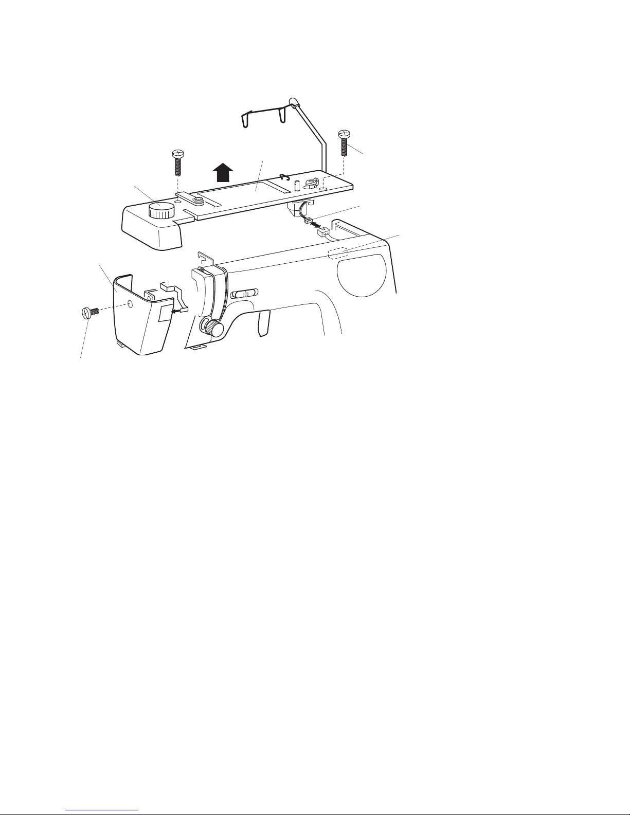
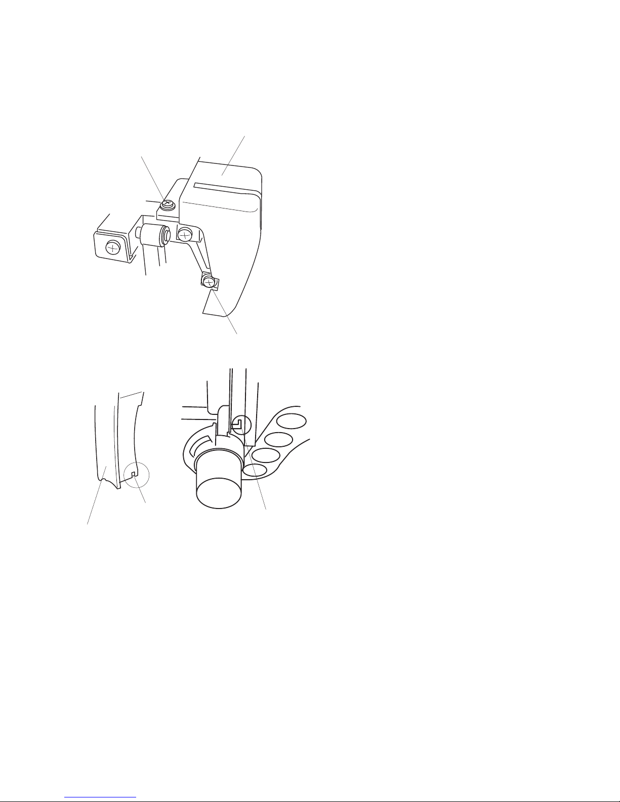
1
Setscrew (A)
Face plate
Top cvoer
Setscrew (B)
Setscrew (C)
Connector (D)
Connector case
Pressure dial
Face plate
[ To remove]
Remove the setscrew (A) to remove the face plate.
[ To attach]
Attach the face plate with the setscrews (A).
Top cover
[ To remove ]:
1. Remove the setscrews (B) and (C).
2. Pull out the connector (D) of the bobbin winder and remove the top cover.
[ To attach ]:
3. Connect the connector of the bobbin winder and tighten the setscrews (B) and (C).
TO REMOVE FACE PLATE AND TOP COVER
2
Setscrew (B)
Setscrew A)
Machine base
Setscrew (A)
Setscrew (C)
Belt cover
Setscrew (B)
Projection (F)
Projection (E)
Rubber
plug
Washer
Setscrew (E)
Machine rest
(20 cm high)
Belt cover
[ To remove ]:
1. Remove the setscrews (A), (B) and (C).
2. Remove the belt cover
[ To attach ]:
3. Insert the projections (D), (E) and (F) and
tighten the setscrews (A), (B) and (C).
Machine base
[ To remove ]:
Remove the 3 setscrews (A), (B) and (C)
[ To attach]
Attach the machine base with the 3 setscrews
(A), (B) and (C).
Setscrew (D)
Setscrew (C)
TO REMOVE BELT COVER AND MACHINE BASE
3
Setscrew (A)
Auto hread
cutter cover
TO REMOVE AUTO THREAD CUTTER COVER
[ To remove ]:
Loosen the setscrew (A) and pull off the auto hread
cutter cover.
[ To attach ]:
Replace the auto thread cutter cover and tighten
the setscrew (A).
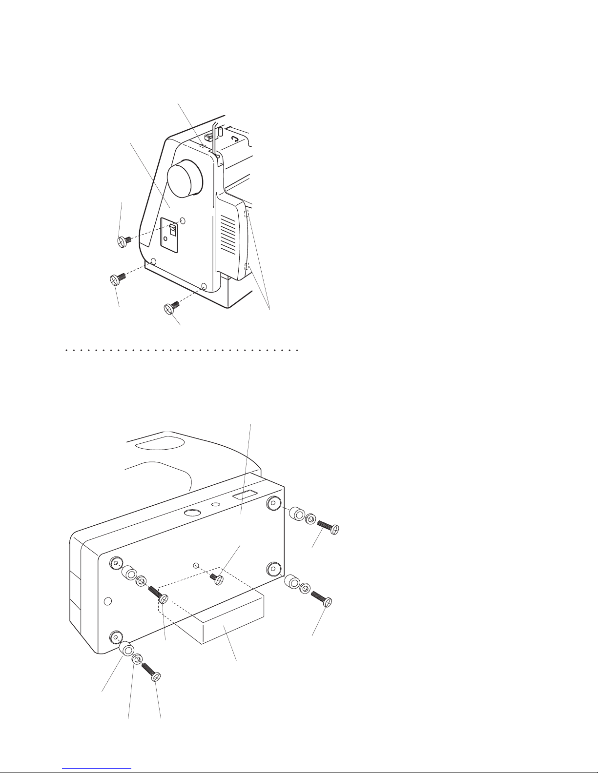
4
Setscrew (A)
Setscrew (C)
Setscrew (B)
Setscrew (D)
Front cover
[View from belt
cover side]
Insulation paper
Cords
Setscrew (B)
Circuit board A
[ To remove ]:
1. Remove the face plate, top cover and belt cover
(refer to pages 1 and 2).
2. Loosen the setscrews (A), (B), (C) and (D).
3. Pull out the connectors (refer to page 10) and
remove the front cover.
[ To attach ]:
4. Proceed with the above procedure in reverse.
When attaching the front cover, ensure that the
cords shown in the photo on the left do not get
caught between the cover and the parts.
TO REMOVE FRONT COVER
5
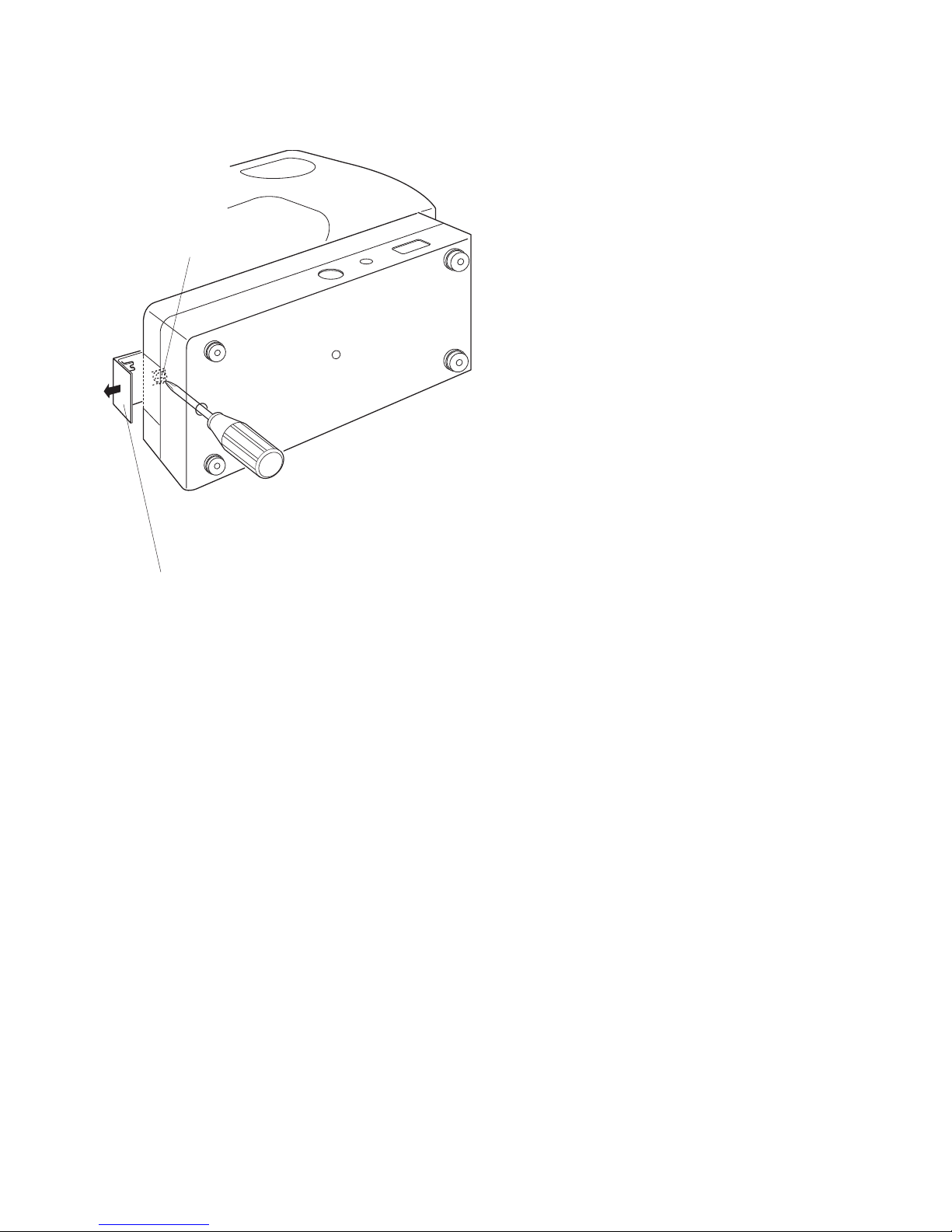
TO REMOVE COVER
Setscrew (A)
Setscrew (B)
Cover (D)
Cover (D)
Groove (E)
“C” part
[ To remove ]
1. Remove the face plate and top cover (refer to
page 1).
2. Loosen the setscrews (A) and (B).
Remove the cover (D).
[ To attach ]
Reverse the above procedure.
* Take care when removing and attaching the
cover, as the right hand side of cover is held in
position by the “C” part slipping into the groove
(E) of the cover (D).
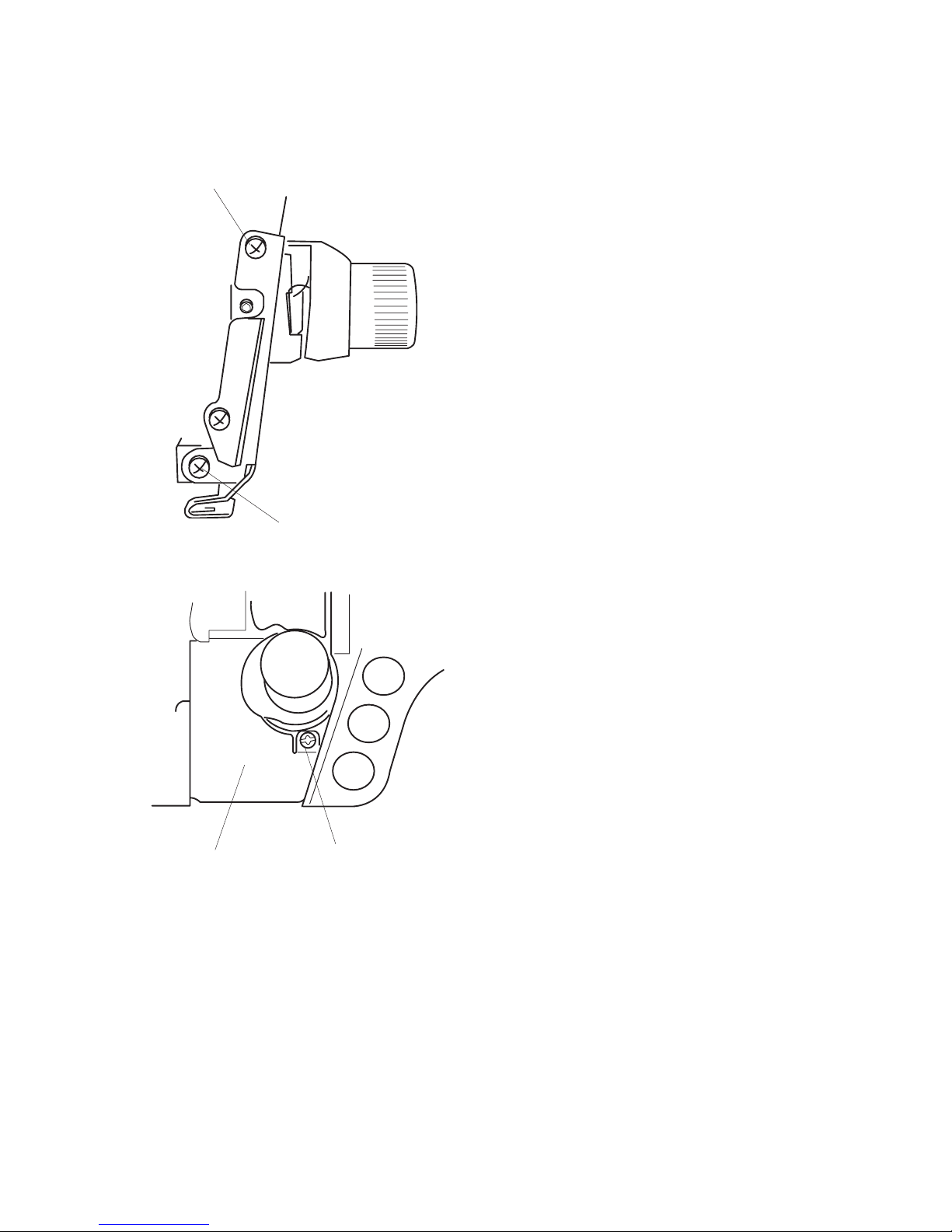
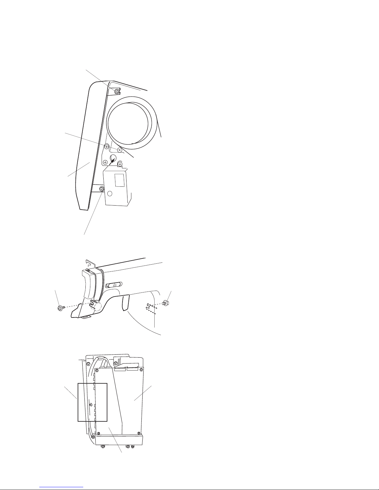
6
Setscrew (A)
Setscrew (B)
Setscrew (C)
Thread guide (D)
TO REMOVE THE THREAD GUIDE
[ To remove ]
Remove the face plate, and tilt the lamp socket (E)
to the left.
Remove the setscrews (A), (B) and (C), and emove
the thread guide (D).
[ To attach ]
Reverse the above procedure.
7
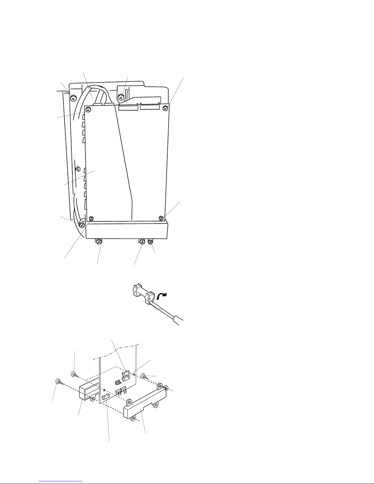
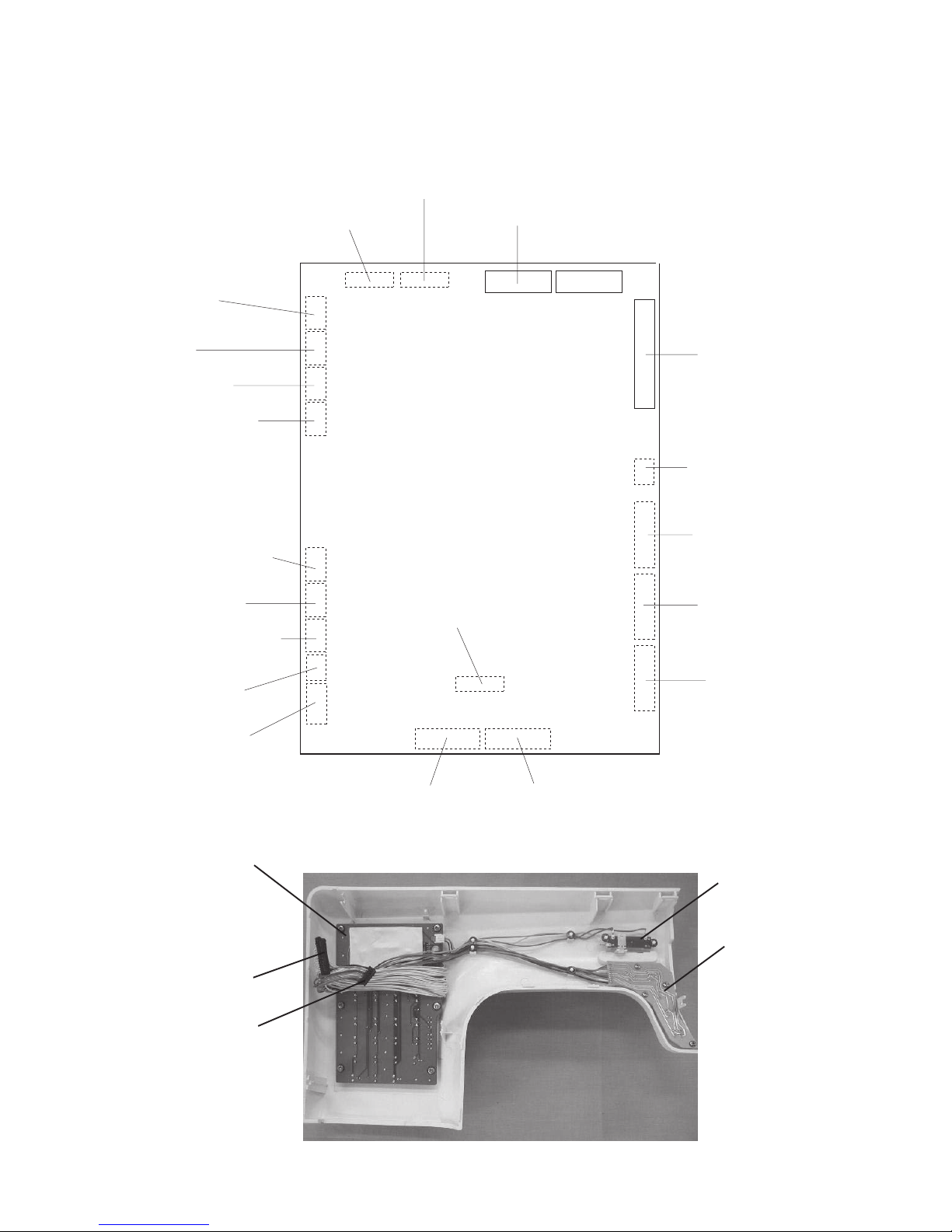
TO REPLACE CIRCUIT BOARD A AND FUSE
Circuit board A
Setscrew
(A)
Setscrew (A)
Setscrew (A)
Setscrew (A)
Mounting bracket
Insulation
paper
Setscrew (B)
Setscrew (B)
Setscrew (C)
Setscrew (C)
A board case
A board
case Lid
Setscrew (B)
Setscrew (D)
Setscrew (D)
(F1) 3.15A
Part No. 00182904
(F2) 2.5A
Part No. 000144605
(F2) 2.5A
Part No. 000144605
Setscrew
(C)
Setscrew (C)
[To remove]
1. Remove the front cover (refer to page 4).
2. Remove the 4 setscrews (A).
Remove the circuit board A together with the
mounting bracket.
3. Remove the 2 setscrews (D).
4. Remove the 2 setscrews (B) and 2 setscrews
(C).
5. Remove the circuit board A and lid.
[To attach]
Reverse the above procedure.
* The shiny side of the insulation paper should
face the circuit board A.
[To change the fuse]
1. Remove the 2 setscrews (B) and 2 setscrews
(C).
2. Remove the circuit board A and lid.
3. Pry the fuse out with a screwdriver as shown.
I
f the fuse is loose, bend the fuse holder with
your fingers.
8
TO REPLACE CIRCUIT BOARD K
Setscrew
Setscrew
Connector of the
speed control lever
[To remove]
1. Remove the front cover (refer to page 4).
2. Pull out the connector of the speed control
lever.
3. Remove the 8 setscrews.
[To attach]
Reverse the above procedure.
9
TO REPLACE CIRCUIT BOARD F AND SPEED CONTROL LEVER
Circuit board F
CS ring (E)
Speed control lever (C)
Setscrew (A)
CS ring (E)
Connector
(B)
[To remove the circuit board F]
1. Remove the front cover (refer to page 4).
2. Pull out the connector from the circuit board A.
(refer to page 7).
3. Remove the 3 setscrews (A) and 2 CS rings (D).
[To attach]
Reverse the above procedure.
Make sure that the buttons are placed in the
correct places and direction.
[To remove the speed control lever]
1. Remove the front cover (refer to page 4).
2. Pull out the connector (B) from the circuit board
K.
3. Remove the 2 CS rings (E), and remove the
speed control lever (C).
[To attach]
Reverse the above procedure.
10
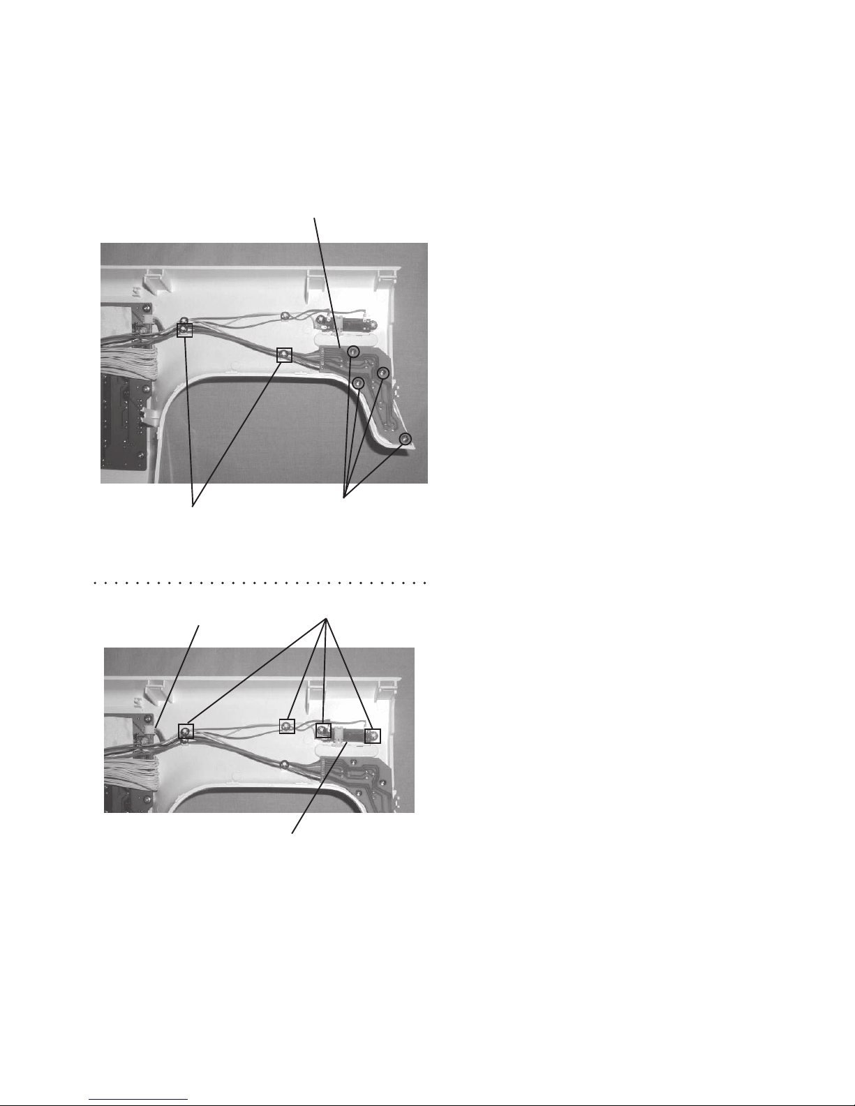
CONNECTION OF CONNECTORS
Circuit board F
(black 7 pins)
Zigzag stepping
motor
(white 7 pins)
Feed stepping
motor
(black 7 pins)
Lamp
(white 2 pins)
Drop feed switch
(blue 2 pins)
DC motor
(white 5 pins)
Foot control
(white 2 pins)
Lower shaft sensor
(black 5 pins)
Bobbin winder
(black 4 pins)
Buttonhole sensor
(black 3 pins)
Circuit board K
(black 32 pins)
Presser bar switch
(black 2 pins)
Motor for thread
tension release
(red 7 pins)
Auto thread cutter
switch
(red 2 pins)
Separation solenoid
(red 2 pins)
Bobbin solenoid
(black 2 pins)
Transformer
(secondary)
(red 6 pins)
Transformer
(primary)
(black 2 pins)
Machine socket
(white 2 pins)
Connector to circuit
board K
Circuit board F
CIRCUIT BOARD A
Circuit board K
Speed control lever
Auto thread cutter
solenoid (white 2 pins)
Connector to
circuit
board F
11
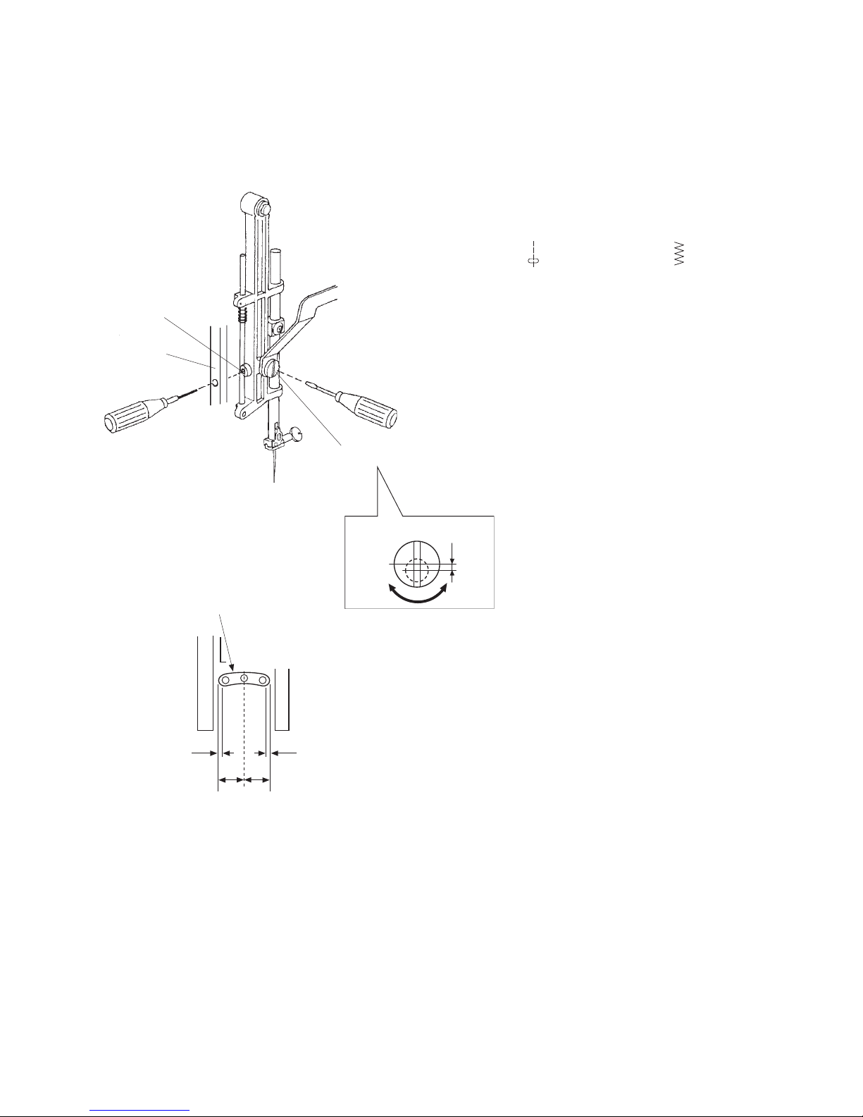
[ To adjust ]:
1. Remove the face plate.
Check the needle drop position on the stitch
pattern ( ) and zigzag stitch ( ) with
maximum width.
2. Loosen the hexagonal socket screw (A) just
enough to turn the eccentric pin (B).
The direction of the eccentric pin (B) should be
as shown in the Fig. 1.
3. Tighten the hexagonal socket screw (A).
4. Attach the face plate.
Hole of needle plate
0.2mm or
more
0.2mm or
more
A = B
Hexagonal
socket screw (A)
Threader lever
TO ADJUST NEEDLE DROP POSITION
When the straight stitch is selected, the needle should be at the center of the hole of the needle plate.
When the maximum zigzag width is selected, the distance between the needle and the edge of the hole
of the needle plate at the right and left needle positions should be 0.2mm or more as shown in Fig. 2.
Eccentric pin (B)
Fig. 1
Fig. 2
12
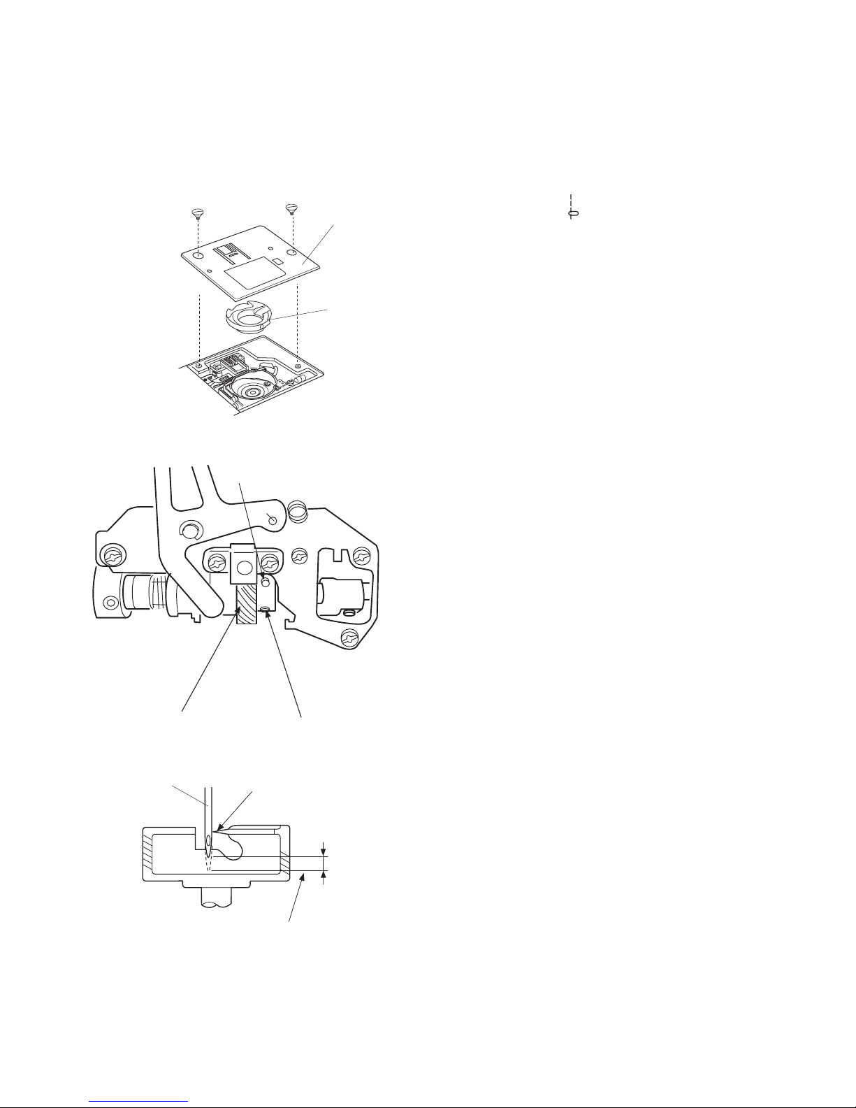
[ To adjust ]:
1. Remove the machine base (refer to page 2)
2. Turn the power switch on and select stitch
pattern No. 2 ( ) in mode 1.
3. Set the zigzag width at 0 and turn the power
switch off.
4. Remove the presser foot, needle plate and
bobbin holder.
5. Turn the balance wheel toward you to set the
needle bar at its lowest position.
6. Loosen the hexagonal socket screws (A) and
(B) on the lower shaft gear (C).
7. Move the needle bar between 3.25mm and
3.55mm from the lowest position.
8. Turn the lower shaft gear (C) until the tip of the
hook meets the right side of the needle.
9. Tighten the hexagonal socket screws (A) and
(B).
10. Attach the bobbin holder, needle plate and
presser foot.
11. Attach the machine base.
Hexagonal socket screw (A)
Hexagonal
socket
screw (B)
Lower shaft
gear (C)
3.25 – 3.55mm
Lowest
position
Needle,
size 14
Tip of hook
Needle
plate
Bobbin
holder
TO ADJUST HOOK TIMING
The movement of the needle from its lowest point to its highest point should be in the range of 3.25 to
3.55mm.
13
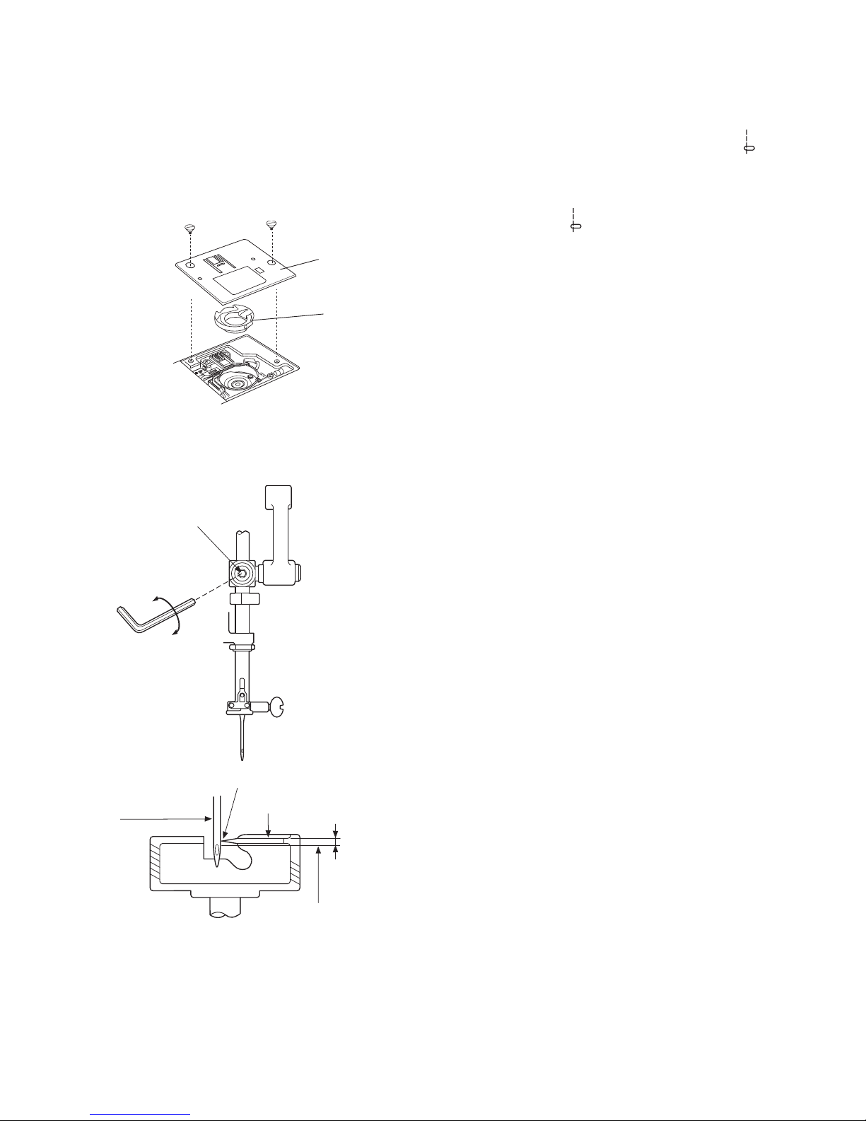
[ To adjust ]:
1. Turn the power switch on and select stitch
pattern No. 2 ( ) in mode 1.
2. Set the zigzag width at 0 and turn the power
switch off.
3. Remove the presser foot, needle plate (A),
bobbin holder (B) and face plate.
4. Remove the arm thread guide and face plate.
5. Turn the balance wheel toward you until the tip
of the hook meets the right side of the needle.
6. Loosen the hexagonal socket screw (G).
7. Move the needle bar to adjust the needle bar.
Fix the arm thread guide and face plate guide.
9. Attach the arm thread guide, face plate, bobbin
holder, needel plate (A) and presser foot.
Needle
plate (A)
Bobbin
holder (B)
Point of hook
Hook race
Needle,
size 14
1.6 – 2.0mm
Upper edge of
needle eye
Hexagonal
socket screw
(G)
TO ADJUST NEEDLE BAR HEIGHT
Before proceeding with this adjustment, check the hook timing (refer to page 12).
The distance between the upper edge of the needle eye and the tip of the hook should be in the range of
1.6 – 2.0mm when the tip of the hook meets the right side of the needle in the left needle position ( ) as
the needle ascends from its lowest position.
 Loading...