

Page 1

Jackson MSC, Inc.
P.O. BOX 1060
BARBOURVILLE, KY. 40906
FAX (606) 523-9196
PHONE (606) 523-9795
Company
CHEMICAL DISPENSING UNIT
TECHNICAL MANUAL
INSTALLATION MANUAL FOR DOMESTIC UNITS
INSTALLATION MANUAL FOR EXPORT UNITS
SERVICE MANUAL FOR DOMESTIC UNITS
FOR JACKSON MODELS:
HT-1
HT-2
LT-1
LT-3
An
June 29, 2004
P/N 7610-002-54-60 (Revision D)
HWY. 25E
www.jacksonmsc.com
Page 2

Page 3

REVISION
D 06-29-04 MAW N/A CONVERTED TO NEW LAYOUT
REVISION
DATE
MADEBYAPPLICABLE
ECN
DETAILS
i
Page 4

NOMENCLATURE FOR THE MODELS COVERED IN THIS MANUAL:
LT-3
HT-1 = Detergent dispensing unit for high temp dishmacines.
HT-2 = Detergent and rinse aid dispensing unit for high temp dishmachines.
LT-1 = Sanitizer dispensing unit for low temp dishmachines.
LT-3 = Detergent, rinse aid, and sanitizer dispensing unit for low temp dishmachines.
Model:
Serial No.:
Installation Date:
Service Rep. Name:
Phone No.:
Jackson MSC Inc. provides technical support for all
of the dishmachines detailed in this manual. We
strongly recommend that you refer to this manual
before making a call to our technical support staff.
Please have this manual with you when you call so
that our staff can refer you, if necessary, to the proper page. Technical support is available from 8:00
a.m. to 5:00 p.m. (EST), Monday through Friday.
Technical support is not available on holidays.
Contact technical support toll free at 1-888-800-
5672. Please remember that technical support is
available for service personnel only.
ii
Page 5

TABLE OF CONTENTS
SECTION DESCRIPTION PAGE
I. SPECIFICATION INFORMATION
Dimensions 2
II. INSTALLATION/OPERATION INSTRUCTIONS
Installation & Operation Instructions, HT-1 & HT-2 4
Installation & Operation Instructions, LT-1 & LT-3 5
Installation Instructions & Diagrams, HT-1 & HT-2 7
Installation Instructions & Diagrams, LT-1 & LT-3 8
Chemical Dispensing Equipment, HT-1 & HT-2 9
Chemical Dispensing Equipment, LT-1 & LT-3 10
Cam Timer Operation HT-1 11
Cam Timer Operation HT-2 13
Cam Timer Operation LT-1 15
Cam Timer Operation LT-3 17
III. PARTS
HT-1 Assembly 20
HT-2 Assembly 22
Inner Panel Assembly 24
LT-1 Assembly 25
LT-3 Assembly 27
Peristaltic Pump Assembly 29
IV. ELECTRICAL SCHEMATICS
HT-1 208-240V, 60HZ, 1 PHASE 31
HT-2 115V, 60HZ, 1 PHASE 32
HT-2 208-240V, 60HZ, 1 PHASE 33
LT-1 115V, 60HZ, 1 PHASE 34
LT-3 115V, 60HZ, 1 PHASE 35
LT-3 208-240V, 60HZ, 1 PHASE 36
V. JACKSON MAINTENANCE & REPAIR CENTERS 38
iii
Page 6

SECTION 1:
SPECIFICATION INFORMATION
1
Page 7
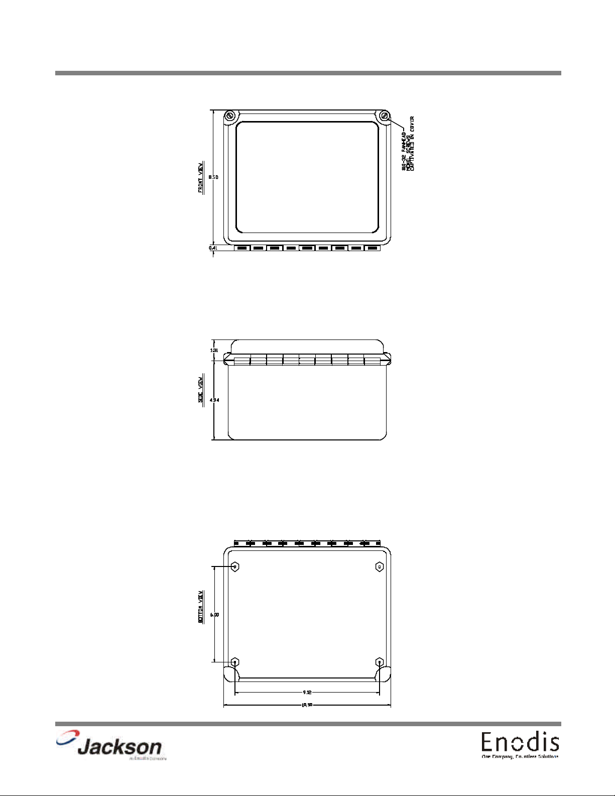
DIMENSIONS
SECTION 1: SPECIFICATION INFORMATION
2
Page 8

SECTION 2:
INSTALLATION/OPERATION
INSTRUCTIONS
3
Page 9

SECTION 2: INSTALLATION/OPERATION INSTRUCTIONS
INSTALLATION/OPERATION INSTRUCTIONS HT-1 & HT-2 DISPENSERS
Mount the chemical dispenser unit in a convienent location on the wall.
VERY IMPORTANT: Do not use a domestic type detergent in this machine at any time. This type of detergent may damage
and/or obstruct pump operation or cause corrosion in the tank.
HT-1 DISPENSING EQUIPMENT- ELECTRICAL CONNECTION: Power and signal source for the detergent and rinse aid are provided as follows:
1. DETERGENT SIGNAL-White/red wire, signal (line voltage) for detergent dispensing. Connected between the normally closed
contact (N.C.) of C6 cam and the Detergent Pump Motor (SM) also connecting to the Detergent Prime Switch (S4). Detergent will
be dispensed during the rinse cycle.
2. DISPENSER POWER-White wire (line voltage). Connected between Detergent Primer Switch (S4) and the On/Fill-Off/Drain
Switch (S1).
All conduit and wiring for the interconnections is shipped pre-mounted to the HT-1 Chemical Dispensing Equipment. For connections to the dishmachine the wires terminate with butt splice connectors. When installing the chemical dispensing wiring match the
correct wire colors then crimp the connectors.
HT-2 DISPENSING EQUIPMENT- ELECTRICAL CONNECTION: Power and signal source for the detergent and rinse aid are provided as follows:
1. DETERGENT SIGNAL-White/red wire, signal (line voltage) for detergent dispensing. Connected between the normally closed
contact (N.C.) of C6 cam and the detergent terminal of the Speed Control Circuit Board (SC). Detergent will be dispensed during
the rinse cycle.
2. DISPENSER POWER-Red wire, (line voltage) Connected between “L2” and the “C” terminal on the step-down transformer in
the HT-2 box.
3. DISPENSER POWER-White wire (line voltage). Connected between “L1” and the appropriate line voltage terminal on the stepdown transformer in the HT-2 box.
4. RINSE AID SIGNAL-Blue wire, (line voltage). Signal for dispensing the rinse aid. Connected between the normally closed contact (N.C.) of the C5 cam and the rinse aid terminal of the Speed Control Circuit Board (SC). Rinse aid will be injected into the final
rinse line during the rinse cycle.
All conduit and wiring for the interconnections is shipped pre-mounted to the HT-2 Chemical Dispensing Panel. For connections to
the dishmachine the wires terminate with butt splice connectors. When installing the chemical dispensing wiring match the correct
wire colors then crimp the connectors.
DETERGENT RECOMMENDATIONS: We suggest that you contact your local detergent specialist for the correct detergent for your
area.
LIQUID DETERGENT DISPENSING POINT: Liquid detergent will be dispensed into machine from factory supplied hole at back of
the tub above the basket strainer. Remove factory installed plug and install injector fitting for the detergent.
RINSE ADDITIVE INJECTION-FINAL RINSE LINE (HT-2 ONLY): Rinse Aid will be injected into the final rinse line at the rear of the
machine. Remove one of the 1/4” plugs from the line and install the rinse aid injector fitting.
TIMER ADJUSTMENT FOR DETERGENT CONCENTRATION: The amount of detergent may need to be increased or decreased
depending on water quality and type of detergent. It is factory set to dispense 15 ml of detergent into the wash water during the
rinse cycle. Consult your detergent representative for adjustment.
VOLTAGE CHECK: Ensure that the power switch is in the OFF position and apply power to the dishmachine. Check the incoming
power at the terminal block and ensure it corresponds to the voltage listed on the data plate of the dishmachine. If not, contact a
qualified service agency to examine the problem. Do not run the dishmachine if the voltage is too high or too low. Shut off the service breaker and mark it as being for the dishmachine. Advise all proper personnel of any problems and of the location of the service breaker. Replace the front kick panel and tighten down the screws.
4
Page 10

SECTION 2: INSTALLATION/OPERATION INSTRUCTIONS
INSTALLATION / OPERATION INSTRUCTIONS LT-1 & LT-3 DISPENSERS
The dishmachine is a “DUMP AND FILL” type unit that dumps (drains) the wash water after each washing cycle. Water added
from the fresh water final rinse is used for the next washing cycle.
Mount the chemical dispenser unit in a convienent location on the wall.
VERY IMPORTANT: Do Not use a domestic type detergent in this machine at any time. This type of detergent may damage and/or obstruct pump operation or cause corrosion in the tank.
LT-1 DISPENSING EQUIPMENT- ELECTRICAL CONNECTION: Power and signal source for the sanitizer are provided as follows:
1. SANITIZER SIGNAL-White/red wire, signal (line voltage) for sanitizer dispensing. Connected between the normally closed
contact (N.C.) of C6 cam and the Sanitizer Pump Motor (SM) also connecting to the Sanitizer Prime Switch (S4). Sanitizer will
be dispensed during the rinse cycle.
2. DISPENSER POWER-White wire (line voltage). Connected between Sanitizer Primer Switch (S4) and the On/Fill-Off/Drain
Switch (S1).
All conduit and wiring for the interconnections is shipped pre-mounted to the LT-1 chemical dispensing equipment. For connections to the dishmachine the wires terminate with butt splice connectors. When installing the chemical dispensing wiring
match the correct wire colors then crimp the connectors.
LT-3 DISPENSING EQUIPMENT- ELECTRICAL CONNECTION: Power and signal source for the detergent and rinse aid are
provided as follows:
1. SANITIZER SIGNAL-White/red wire, signal (line voltage) for sanitizer dispensing. Connected between the normally closed
contact (N.C.) of C6 cam and the Sanitizer Pump Motor (SM) also connecting to the Sanitizer Prime Switch (S4). Sanitizer will
be dispensed during the rinse cycle.
2. DISPENSER POWER-White wire (line voltage). Connected between Sanitizer Primer Switch (S4) and the On/Fill-Off/Drain
Switch (S1).
3. DETERGENT SIGNAL-White/red wire, signal (line voltage) for detergent dispensing. Connected between the normally
closed contact (N.C.) of C7 cam and the Detergent Pump Motor (DM) also connecting to the Detergent Prime Switch (S5).
Detergent will be dispensed during the rinse cycle.
4. DISPENSER POWER-White wire (line voltage). Connected between Detergent Primer Switch (S5) and the On/Fill-
Off/Drain Switch (S1).
5. RINSE ADDITIVE SIGNAL-White/red wire, signal (line voltage) for rinse additive dispensing. Connected between the normally closed contact (N.C.) of C8 cam and the Rinse Aid Pump Motor (RM) also connecting to the Rinse Aid Prime Switch (S6).
Rinse Aid will be dispensed during the rinse cycle.
6. DISPENSER POWER-White wire (line voltage). Connected between Rinse Aid Primer Switch (S6) and the On/Fill-Off/Drain
Switch (S1).
All conduit and wiring for the interconnections is shipped pre-mounted to the LT-3 chemical dispensing panel. For connections
to the dishmachine the wires terminate with butt splice connectors. When installing the chemical dispensing wiring match the
correct wire colors then crimp the connectors.
SANITIZER RECOMMENDATIONS: We suggest that you contact your local chemical specialist for the correct sanitizer for
your application.
DETERGENT RECOMMENDATIONS AND RINSE ADDITIVES (LT-3 Only): We suggest that you contact your local detergent
specialist for the correct detergent and rinse additives for your area.
5
Page 11

SECTION 2: INSTALLATION/OPERATION INSTRUCTIONS
INSTALLATION / OPERATION INSTRUCTIONS LT-1 & LT-3 DISPENSERS (CONTINUED)
LIQUID DETERGENT DISPENSING POINT (LT-3 Only): Liquid detergent will be dispensed into machine from factory supplied
hole at back of the tub above the basket strainer. Remove factory installed plug and install injector fitting for the detergent.
TIMER ADJUSTMENT FOR DETERGENT CONCENTRATION (LT-3 Only): The amount of detergent may need to be
increased or decreased depending on water quality and type of detergent. It is factory set to dispense 15 ml of detergent into
the wash water during the rinse cycle. Consult your detergent representative for adjustment.
RINSE ADDITIVE INJECTION-FINAL RINSE LINE (LT-3 ONLY): Rinse Aid will be injected into the final rinse line at the rear
of the machine. Remove one of the 1/4” plugs from the line and install the rinse aid injector fitting.
SANITIZER INJECTION-FINAL RINSE LINE: Sanitizer will be injected into the final rinse line at the rear of the machine.
Remove one of the 1/4” plugs from the line and install the sanitizer injector fitting.
TIMER ADJUSTMENT FOR SANITIZER CONCENTRATION: The amount of sanitizer may need to be increased or decreased
depending on concentration and type of sanitizer used. The dispenser needs to be able to provide 2.271 ml of a 10% Chlorine
sanitizer for every machine cycle.
VOLTAGE CHECK: Ensure that the power switch is in the OFF position and apply power to the dishmachine. Check the incoming power at the terminal block and ensure it corresponds to the voltage listed on the data plate of the dishmachine. If not, contact a qualified service agency to examine the problem. Do not run the dishmachine if the voltage is too high or too low. Shut
off the service breaker and mark it as being for the dishmachine. Advise all proper personnel of any problems and of the location of the service breaker. Replace the front kick panel and tighten down the screws.
6
Page 12
SECTION 2: INSTALLATION/OPERATION INSTRUCTIONS
INSTALLATION INSTRUCTIONS & DIAGRAMS for the HT-1 & HT-2
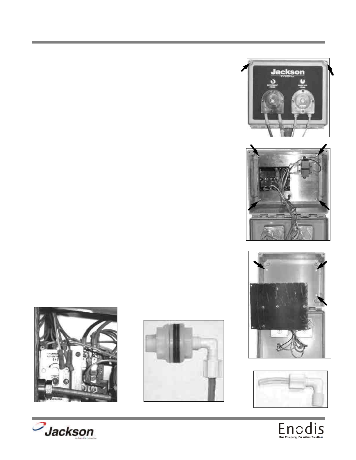
Installation Instructions:
1. Identify the appropriate location for the box.
2. Make sure the electrical supply to the dishmachine has been turned off at the supply circuit
breaker.
3. Loosen the two screws in the upper corners of the box and open. (See photo #1)
4. Loosen and remove the four screws to the component mounting plate inside. (Removing the
ground screw will give additional slack.) (See photo #2)
5. Hold the box up to the wall and mark four mounting holes. (See photo #3)
6. Install appropriate wall anchors for the type of wall.
7. Mount the box to the wall.
8. Replace the component mounting plate. Reinstall the ground screw.
9. Close the box and retighten screws.
10. Run flexible conduit to rear of dishmachine and attach with fitting provided.
11. Remove the front kick panel from the dishmachine by loosening the screws under the front
two corners and lifting upward and out.
12. Locate the wire bundle above the thermostat. (See photo #4) There will be four wires (white,
red, blue and white with a red stripe) all with red crimp-type butt splices.
13. Run the five wires from the conduit to the front of the unit and match up color to color with
the wire bundle. Cut wires from the conduit to proper length, if needed.
14. Crimp all wires to matching color on dishmachine. Attach green and yellow wire to grounding lug. Use wire ties to route wires out of the way of moving parts.
15. Reinstall the kick panel on the dishmachine.
16. Locate and remove the white bulkhead plug on the rear of the dishmachine.
17. Install the bulkhead fitting from the kit (bulkhead with a hole through the center) in its place.
(See photo #5) Install one of the compression elbows into the bulkhead fitting. Route the red
chemical tube into the compression elbow and hand tighten only.
18. Locate the rinse injector on the rear of the dishmachine. Remove one of the square headed
plugs. Wrap the compression elbow threads with plumber’s teflon tape and install the elbow into
the hole.
19. Insert a short piece of clear tubing from the kit into the other compression elbow. Route the
white tubing from the dispenser to the compression elbow. Insert white tube through clear tube
in compression elbow and hand tighten only. (See photo #6)
20. Power up the unit and run a cycle and check for leaks.
21. Put the unit back in place.
22. Place the gray stiffeners in the appropriate chemicals. (red for detergent, and white for rinse
aid)
23. Prime each pump until chemical is seen flowing through tube going into the unit.
24. Installation is complete.
Photo #1
Photo #2
Photo #4
Photo #3
Photo #5
Photo #6
7
Page 13
SECTION 2: INSTALLATION/OPERATION INSTRUCTIONS
INSTALLATION INSTRUCTIONS & DIAGRAMS for the LT-1 & LT-3
1. Identify the appropriate location for the box.
2. Make sure the electrical supply to the dishmachine has been turned off at the supply circuit breaker.
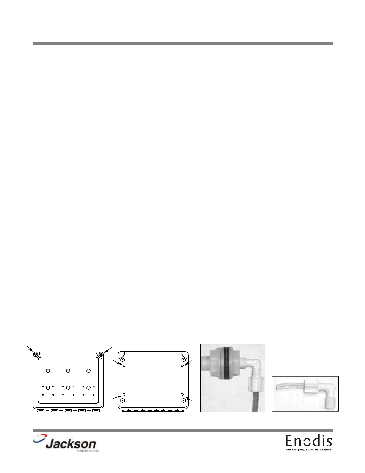
3. Loosen the two screws in the upper corners of the box and open. (See diagram #1)
4. Hold the box up to the wall and mark four mounting holes. (See diagram #2)
5. Install appropriate wall anchors for the type of wall.
6. Mount the box to the wall.
7. Close the box and retighten screws.
8. Run flexible conduit to rear of dishmachine and attach with fitting provided.
9. Remove the front kick panel from the dishmachine by loosening the screws under the front two corners and lifting upward
and out.
10. Locate the wire bundle above the thermostat. There will be four wires (white, red, blue and white with a red stripe) all with
red crimp-type butt splices.
11. Run the five wires from the conduit to the front of the unit and match up color to color with the wire bundle. Cut wires from
the conduit to proper length, if needed.
12. Crimp all wires to matching color on dishmachine. Attach green and yellow wire to grounding lug. Use wire ties to route
wires out of the way of moving parts.
13. Reinstall the kick panel on the dishmachine.
14. Locate and remove the white bulkhead plug on the rear of the dishmachine.
15. Install the bulkhead fitting from the kit (bulkhead with a hole through the center) in its place. (See diagram #3) Install one
of the compression elbows into the bulkhead fitting. Route the red chemical tube into the compression elbow and hand tighten
only.
16. Locate the rinse injector on the rear of the dishmachine. Remove one of the square headed plugs. Wrap the compression
elbow threads with plumber’s teflon tape and install the elbow into the hole.
17. Insert a short piece of clear tubing from the kit into the other compression elbow. Route the white tubing from the dispenser
to the compression elbow. Insert white tube through clear tube in compression elbow and hand tighten only. (See diagram #4)
18. Power up the unit and run a cycle and check for leaks.
19. Put the unit back in place.
20. Place the gray stiffeners in the appropriate chemicals. (red for detergent, and white for sanitizer, and blue for rinse aid)
21. Prime each pump until chemical is seen flowing through tube going into the unit.
22. Installation is complete.
Diagram #1
Diagram #2
Diagram #4Diagram #3
8
Page 14

SECTION 2: INSTALLATION/OPERATION INSTRUCTIONS
CHEMICAL DISPENSING EQUIPMENT HT-1 & HT-2
TO PREPARE PUMPS FOR OPERATION
The HT-1 is a chemical dispensing unit supplied with a detergent pump. Locate the open end of the chemical tube with the tube
stiffener and place in the appropriate container.
The HT-2 is a chemical dispensing unit supplied with detergent and rinse additive pumps. Locate the open ends of the chemical tubes with the tube stiffeners and place each one in the appropriate container.
A. Red Tubing = Detergent
B. Blue Tubing (HT-2 Only) = Rinse Aid
PRIMING CHEMICAL FEEDER PUMPS
Chemical feeder pumps need priming when the machine is first installed or if for some reason the chemical lines have been
removed and air has been allowed to enter.
CAUTION: Water must be in the sump and wash tank prior to the dispensing of the chemical.
1. Verify that the chemical tube stiffener inlet is in the detergent container.
2. Use the toggle switches on the front of the dispenser box to prime each pump. There is one (1) switch mounted above each
peristaltic pump. One will prime the detergent pump, and the second will prime the rinse aid pump (HT-2 Only).
3. To prime the pump, hold the switch in the momentary position until chemical can be observed entering the tub.
4. Detergent is dispensed as required during the wash cycle by the cam timer. The amount of detergent may need to be
increased or decreased depending on water quality and type of detergent. It is adjusted by changing Cam 6 on the cam timer.
5. Rinse additive is dispensed as required into the final rinse. The amount of rinse aid may need to be adjusted depending on
water hardness and results. It can be changed by changing Cam 5 on the cam timer.
WARNING: Some of the chemicals used in dishwashing may cause chemical burns if they come on contact with
your skin. Wear appropriate protective gear when handling these chemicals. If you do come in contact with
these chemicals flush the area with fresh water.
9
Page 15

SECTION 2: INSTALLATION/OPERATION INSTRUCTIONS
CHEMICAL DISPENSING EQUIPMENT LT-1 & LT-3
TO PREPARE PUMPS FOR OPERATION
The LT-1 is a chemical dispensing unit supplied with a sanitizer chemical pump. Locate the open end of the chemical tube with
the tube stiffener and place in the appropriate container.
The LT-3 is a chemical dispensing unit supplied with detergent, rinse additive, and sanitizer chemical pumps. Locate the open
ends of the chemical tubes with the tube stiffeners and place each one in the appropriate container.
A. Red Tubing = Detergent
B. Blue Tubing (LT-3 Only) = Rinse Aid
C. White Tubing (LT-3 Only) = Sanitizer
PRIMING CHEMICAL FEEDER PUMPS
Chemical feeder pumps need priming when the machine is first installed or if for some reason the chemical lines have been
removed and air has been allowed to enter.
CAUTION: Water must be in the sump and wash tank prior to the dispensing of the chemical.
1. Verify that the proper chemical tube stiffener inlet is in the proper container.
2. Use the toggle switches on the front of the dispenser box to prime each pump. There is one (1) switch mounted above each
peristaltic pump. One will prime the detergent pump, and the second will prime either the rinse aid pump.
3. To prime the pumps, hold the switch in the momentary position until chemical can be observed entering the tub.
4. Sanitizer, either chlorine or iodine, is dispensed into the final rinse. The amount of sanitizer may need to be adjusted depending on the concentration and type of sanitizer used. It is adjusted by changing Cam 6 on the cam timer.
5. Detergent is dispensed as required during the wash cycle by the cam timer. The amount of detergent may need to be
increased or decreased depending on water quality and type of detergent. It is adjusted by changing Cam 7 on the cam timer.
6. Rinse additive is dispensed as required into the final rinse. The amount of rinse aid may need to be adjusted depending on
water hardness and results. It can be changed by changing Cam 8 on the cam timer.
WARNING: Some of the chemicals used in dishwashing may cause chemical burns if they come on contact with
your skin. Wear appropriate protective gear when handling these chemicals. If you do come in contact with
these chemicals flush the area with fresh water.
10
Page 16

SECTION 2: INSTALLATION/OPERATION INSTRUCTIONS
CAM TIMER OPERATION FOR HT-1
The cam timer is a 2 minute 6 cam timer with an OFF-DRAIN function.
The following is a description of set points for each cam and function for each switch.
CAM 1: Cam 1 is a cut cam with a single notch and serves as the Cycle/Reset.
FUNCTION: When the machine is in the operation mode the notch is the home position. The machine will set idle until the door
is opened, then cam 1 moves to the start position and holds until the door is closed. The closing of the door will start the next
cycle. The cam will rotate a complete cycle and back to the home position and hold.
CAM 2: Cam 2 is a cut cam and provides the off/drain function.
FUNCTION: The function of the off/drain cam is controlled by the power switch. When the power switch is in the ON position
the off/drain function is disabled. To use the off/drain, start a cycle and place the power switch in the OFF position. The machine
will run a wash cycle, drain and stop. The machine will hold this state of operation until the power switch is turned on, when
turned on the machine will fill, run a rinse cycle and stop at the home position.
The off/drain cam works off the normally open contacts of cam 2. This requires the switch to be held closed by the cam. The
off/drain cam switch will pick up just after the cycle cam switch and drop back down just after the wash cycle cam switch.
CAM 3: Cam 3 is a cut cam and controls the wash and rinse cycles.
FUNCTION: The wash and rinse cam works off the normally open contacts of cam 3. This requires the switch to be held closed
by the cam. The wash/rinse cam switch will pick up just after the cycle cam switch and drop back down just before the off/drain
cycle cam switch. Wash pump will run approximately 58 seconds. The machine will drain and fill. The rinse cycle will start after
the fill, approximately at the 82 second mark and will last 35 seconds. The machine will then return to the home position.
NOTE: The last 3 cams are adjustable. The following instructions will require that the timer position have the cams to the front
and the motor to the left.
CAM 4: Cam 4 is an adjustable cam and controls the drain valve.
FUNCTION: The drain valve cam works off the normally closed contacts of cam 4. This requires the switch to be held open by
the cam and allowed to drop into the notch to operate the drain valve. The pumped drain and fill cams require adjustment due
to varying water pressure. The drain must be adjusted to remove whatever water the fill brings into the machine.
SETTINGS: The right side of cam 4 must be set to pick up the switch arm just before the wash cycle cam switch drops. If the
drain valve does not close first the water in the drain hose will back up into the pump housing and wash tank.
Any adjustment made to the drain should be made with the left side of cam 4. The adjustment must be moved back into the
wash time until all water is drained from the wash tank.
CAM 5: Cam 5 is an adjustable cam and controls the fill valve.
FUNCTION: The fill valve cam works off the normally closed contacts of cam 5. This requires the switch to be held open by the
cam and allowed to drop into the notch to operate the fill valve. The pumped drain and fill cams require adjustment due to varying water pressure. Cam 5 must be adjusted to fill the wash tank to the proper operating water level. (Remember, the drain
cycle must remove what the fill cycle brings in.)
SETTINGS: The left side of cam 5 must be set to drop in just past the stop point of the off/drain cam. There must be a dwell
between the off/drain and the fill, so that the fill will not run while the machine is in the off state.
Any adjustment made to the fill should be made with the right side of cam 5. Proper water level will be achieved when the water
touches the bottom of the strainer pan.
11
Page 17

SECTION 2: INSTALLATION/OPERATION INSTRUCTIONS
CAM TIMER OPERATION FOR HT-1 (CONTINUED)
CAM 6: Cam 6 is an adjustable cam and controls the detergent pump.
FUNCTION: The detergent pump cam works off the normally closed contacts of cam 6. This requires the switch to be held open
by the cam and allowed to drop into the notch to operate the pump.
SETTINGS: The left side of cam 6 must be set to drop in just past the starting point of the wash cam. The adjustment for detergent volume must be made with the right side of the cam.
12
Page 18

SECTION 2: INSTALLATION/OPERATION INSTRUCTIONS
CAM TIMER OPERATION FOR HT-2
The cam timer is a 2 minute 6 cam timer with an OFF-DRAIN function.
The following is a description of set points for each cam and function for each switch.
CAM 1: Cam 1 is a cut cam with a single notch and serves as the Cycle/Reset.
FUNCTION: When the machine is in the operation mode the notch is the home position. The machine will set idle until the door
is opened, then cam 1 moves to the start position and holds until the door is closed. The closing of the door will start the next
cycle. The cam will rotate a complete cycle and back to the home position and hold.
CAM 2: Cam 2 is a cut cam and provides the off/drain function.
FUNCTION: The function of the off/drain cam is controlled by the power switch. When the power switch is in the ON position
the off/drain function is disabled. To use the off/drain, start a cycle and place the power switch in the OFF position. The machine
will run a wash cycle, drain and stop. The machine will hold this state of operation until the power switch is turned on, when
turned on the machine will fill, run a rinse cycle and stop at the home position.
The off/drain cam works off the normally open contacts of cam 2. This requires the switch to be held closed by the cam. The
off/drain cam switch will pick up just after the cycle cam switch and drop back down just after the wash cycle cam switch.
CAM 3: Cam 3 is a cut cam and controls the wash and rinse cycles.
FUNCTION: The wash and rinse cam works off the normally open contacts of cam 3. This requires the switch to be held closed
by the cam. The wash/rinse cam switch will pick up just after the cycle cam switch and drop back down just before the off/drain
cycle cam switch. Wash pump will run approximately 58 seconds. The machine will drain and fill. The rinse cycle will start after
the fill, approximately at the 82 second mark and will last 35 seconds. The machine will then return to the home position.
NOTE: The last 3 cams are adjustable. The following instructions will require that the timer position have the cams to the front
and the motor to the left.
CAM 4: Cam 4 is an adjustable cam and controls the drain valve.
FUNCTION: The drain valve cam works off the normally closed contacts of cam 4. This requires the switch to be held open by
the cam and allowed to drop into the notch to operate the drain valve. The pumped drain and fill cams require adjustment due
to varying water pressure. The drain must be adjusted to remove whatever water the fill brings into the machine.
SETTINGS: The right side of cam 4 must be set to pick up the switch arm just before the wash cycle cam switch drops. If the
drain valve does not close first the water in the drain hose will back up into the pump housing and wash tank.
Any adjustment made to the drain should be made with the left side of cam 4. The adjustment must be moved back into the
wash time until all water is drained from the wash tank.
CAM 5: Cam 5 is an adjustable cam and controls the fill valve.
FUNCTION: The fill valve cam works off the normally closed contacts of cam 5. This requires the switch to be held open by the
cam and allowed to drop into the notch to operate the fill valve. The pumped drain and fill cams require adjustment due to varying water pressure. Cam 5 must be adjusted to fill the wash tank to the proper operating water level. (Remember, the drain
cycle must remove what the fill cycle brings in.)
SETTINGS: The left side of cam 5 must be set to drop in just past the stop point of the off/drain cam. There must be a dwell
between the off/drain and the fill, so that the fill will not run while the machine is in the off state.
Any adjustment made to the fill should be made with the right side of cam 5. Proper water level will be achieved when the water
touches the bottom of the strainer pan.
CAM 5: Cam 5 is an adjustable cam and also controls the rinse aid pump.
13
Page 19

SECTION 2: INSTALLATION/OPERATION INSTRUCTIONS
CAM TIMER OPERATION FOR HT-2 (CONTINUED)
FUNCTION: The rinse aid pump cam works off the normally closed contacts of cam 5. This requires the switch to be held open
by the cam and allowed to drop into the notch to operate the pump.
SETTINGS: The left side of cam 5 must be set to drop in just past the starting point of the fill cam. The adjustment for rinse aid
volume must be made with the right side of the cam.
CAM 6: Cam 6 is an adjustable cam and controls the detergent pump.
FUNCTION: The detergent pump cam works off the normally closed contacts of cam 6. This requires the switch to be held open
by the cam and allowed to drop into the notch to operate the pump.
SETTINGS: The left side of cam 6 must be set to drop in just past the starting point of the wash cam. The adjustment for detergent volume must be made with the right side of the cam.
14
Page 20

SECTION 2: INSTALLATION/OPERATION INSTRUCTIONS
CAM TIMER OPERATION FOR LT-1
The cam timer is a 2 minute 8 cam timer with an OFF-DRAIN function.
The following is a description of set points for each cam and function for each switch.
CAM 1: Cam 1 is a cut cam with a single notch and serves as the Cycle/Reset.
FUNCTION: When the machine is in the operation mode the notch is the home position. The machine will set idle until the door
is opened, then cam 1 moves to the start position and holds until the door is closed. The closing of the door will start the next
cycle. The cam will rotate a complete cycle and back to the home position and hold.
CAM 2: Cam 2 is a cut cam and provides the off/drain function.
FUNCTION: The function of the off/drain cam is controlled by the power switch. When the power switch is in the ON position
the off/drain function is disabled. To use the off/drain, start a cycle and place the power switch in the OFF position. The machine
will run a wash cycle, drain and stop. The machine will hold this state of operation until the power switch is turned on, when
turned on the machine will fill, run a rinse cycle and stop at the home position.
The off/drain cam works off the normally open contacts of cam 2. This requires the switch to be held closed by the cam. The
off/drain cam switch will pick up just after the cycle cam switch and drop back down just after the wash cycle cam switch.
CAM 3: Cam 3 is a cut cam and controls the wash and rinse cycles.
FUNCTION: The wash and rinse cam works off the normally open contacts of cam 3. This requires the switch to be held closed
by the cam. The wash/rinse cam switch will pick up just after the cycle cam switch and drop back down just before the off/drain
cycle cam switch. Wash pump will run approximately 58 seconds. The machine will drain and fill. The rinse cycle will start after
the fill, approximately at the 82 second mark and will last 35 seconds. The machine will then return to the home position.
NOTE: The last 3 cams are adjustable. The following instructions will require that the timer position have the cams to the front
and the motor to the left.
CAM 4: Cam 4 is an adjustable cam and controls the drain valve.
FUNCTION: The drain valve cam works off the normally closed contacts of cam 4. This requires the switch to be held open by
the cam and allowed to drop into the notch to operate the drain valve. The pumped drain and fill cams require adjustment due
to varying water pressure. The drain must be adjusted to remove whatever water the fill brings into the machine.
SETTINGS: The right side of cam 4 must be set to pick up the switch arm just before the wash cycle cam switch drops. If the
drain valve does not close first the water in the drain hose will back up into the pump housing and wash tank.
Any adjustment made to the drain should be made with the left side of cam 4. The adjustment must be moved back into the
wash time until all water is drained from the wash tank.
CAM 5: Cam 5 is an adjustable cam and controls the fill valve.
FUNCTION: The fill valve cam works off the normally closed contacts of cam 5. This requires the switch to be held open by the
cam and allowed to drop into the notch to operate the fill valve. The pumped drain and fill cams require adjustment due to varying water pressure. Cam 5 must be adjusted to fill the wash tank to the proper operating water level. (Remember, the drain
cycle must remove what the fill cycle brings in.)
SETTINGS: The left side of cam 5 must be set to drop in just past the stop point of the off/drain cam. There must be a dwell
between the off/drain and the fill, so that the fill will not run while the machine is in the off state.
Any adjustment made to the fill should be made with the right side of cam 5. Proper water level will be achieved when the water
touches the bottom of the strainer pan.
15
Page 21

SECTION 2: INSTALLATION/OPERATION INSTRUCTIONS
CAM TIMER OPERATION FOR LT-1 (CONTINUED)
CAM 6: Cam 6 is an adjustable cam and controls the sanitizer pump.
FUNCTION: The sanitizer pump cam works off the normally closed contacts of cam 6. This requires the switch to be held open
by the cam and allowed to drop into the notch to operate the pump.
SETTINGS: The left side of cam 6 must be set to drop in just past the starting point of the wash cam. The adjustment for sanitizer volume must be made with the right side of the cam.
CAM 7: Cam 7 is an adjustable cam and controls the detergent pump.
FUNCTION: The detergent pump cam works off the normally closed contacts of cam 7. This requires the switch to be held open
by the cam and allowed to drop into the notch to operate the pump.
SETTINGS: The left side of cam 7 must be set to drop in just past the starting point of the wash cam. The adjustment for detergent volume must be made with the right side of the cam.
CAM 8: Cam 8 is an adjustable cam and controls the rinse aid pump.
FUNCTION: The rinse aid pump cam works off the normally closed contacts of cam 8. This requires the switch to be held open
by the cam and allowed to drop into the notch to operate the pump.
SETTINGS: The left side of cam 8 must be set to drop in just past the starting point of the wash cam. The adjustment for rinse
aid volume must be made with the right side of the cam.
16
Page 22

SECTION 2: INSTALLATION/OPERATION INSTRUCTIONS
CAM TIMER OPERATION FOR LT-3
The cam timer is a 2 minute 6 cam timer with an OFF-DRAIN function.
The following is a description of set points for each cam and function for each switch.
CAM 1: Cam 1 is a cut cam with a single notch and serves as the Cycle/Reset.
FUNCTION: When the machine is in the operation mode the notch is the home position. The machine will set idle until the door
is opened, then cam 1 moves to the start position and holds until the door is closed. The closing of the door will start the next
cycle. The cam will rotate a complete cycle and back to the home position and hold.
CAM 2: Cam 2 is a cut cam and provides the off/drain function.
FUNCTION: The function of the off/drain cam is controlled by the power switch. When the power switch is in the ON position
the off/drain function is disabled. To use the off/drain, start a cycle and place the power switch in the OFF position. The machine
will run a wash cycle, drain and stop. The machine will hold this state of operation until the power switch is turned on, when
turned on the machine will fill, run a rinse cycle and stop at the home position.
The off/drain cam works off the normally open contacts of cam 2. This requires the switch to be held closed by the cam. The
off/drain cam switch will pick up just after the cycle cam switch and drop back down just after the wash cycle cam switch.
CAM 3: Cam 3 is a cut cam and controls the wash and rinse cycles.
FUNCTION: The wash and rinse cam works off the normally open contacts of cam 3. This requires the switch to be held closed
by the cam. The wash/rinse cam switch will pick up just after the cycle cam switch and drop back down just before the off/drain
cycle cam switch. Wash pump will run approximately 58 seconds. The machine will drain and fill. The rinse cycle will start after
the fill, approximately at the 82 second mark and will last 35 seconds. The machine will then return to the home position.
NOTE: The last 3 cams are adjustable. The following instructions will require that the timer position have the cams to the front
and the motor to the left.
CAM 4: Cam 4 is an adjustable cam and controls the drain valve.
FUNCTION: The drain valve cam works off the normally closed contacts of cam 4. This requires the switch to be held open by
the cam and allowed to drop into the notch to operate the drain valve. The pumped drain and fill cams require adjustment due
to varying water pressure. The drain must be adjusted to remove whatever water the fill brings into the machine.
SETTINGS: The right side of cam 4 must be set to pick up the switch arm just before the wash cycle cam switch drops. If the
drain valve does not close first the water in the drain hose will back up into the pump housing and wash tank.
Any adjustment made to the drain should be made with the left side of cam 4. The adjustment must be moved back into the
wash time until all water is drained from the wash tank.
CAM 5: Cam 5 is an adjustable cam and controls the fill valve.
FUNCTION: The fill valve cam works off the normally closed contacts of cam 5. This requires the switch to be held open by the
cam and allowed to drop into the notch to operate the fill valve. The pumped drain and fill cams require adjustment due to varying water pressure. Cam 5 must be adjusted to fill the wash tank to the proper operating water level. (Remember, the drain
cycle must remove what the fill cycle brings in.)
SETTINGS: The left side of cam 5 must be set to drop in just past the stop point of the off/drain cam. There must be a dwell
between the off/drain and the fill, so that the fill will not run while the machine is in the off state.
Any adjustment made to the fill should be made with the right side of cam 5. Proper water level will be achieved when the water
touches the bottom of the strainer pan.
17
Page 23

SECTION 2: INSTALLATION/OPERATION INSTRUCTIONS
CAM TIMER OPERATION FOR LT-3 (CONTINUED)
CAM 6: Cam 6 is an adjustable cam and controls the sanitizer pump.
FUNCTION: The sanitizer pump cam works off the normally closed contacts of cam 6. This requires the switch to be held open
by the cam and allowed to drop into the notch to operate the pump.
SETTINGS: The left side of cam 6 must be set to drop in just past the starting point of the wash cam. The adjustment for sanitizer volume must be made with the right side of the cam.
CAM 7: Cam 7 is an adjustable cam and controls the detergent pump.
FUNCTION: The detergent pump cam works off the normally closed contacts of cam 7. This requires the switch to be held open
by the cam and allowed to drop into the notch to operate the pump.
SETTINGS: The left side of cam 7 must be set to drop in just past the starting point of the wash cam. The adjustment for detergent volume must be made with the right side of the cam.
CAM 8: Cam 8 is an adjustable cam and controls the rinse aid pump.
FUNCTION: The rinse aid pump cam works off the normally closed contacts of cam 8. This requires the switch to be held open
by the cam and allowed to drop into the notch to operate the pump.
SETTINGS: The left side of cam 8 must be set to drop in just past the starting point of the wash cam. The adjustment for rinse
aid volume must be made with the right side of the cam.
18
Page 24

SECTION 3:
PARTS SECTION
19
Page 25

HT-1 ASSEMBLY
SECTION 3: PARTS SECTION
4
3
2
1
*5
*7
12
10
6
11
13
14
15
16
17
8
9
10
20
18
Page 26

SECTION 3: PARTS SECTION
HT-1 ASSEMBLY (CONTINUED)
ITEM QTY DESCRIPTION Mfg. No.
1 Complete HT-1 Assembly 5700-002-51-98
1 1 Box, Fiberglass Single Chemical Feeder Pump 5700-031-73-03
2 1 Decal, Warning - Disconnect Power 9905-100-75-93
3 1 Chemical Feeder Pump Motor, 240V, 36 RPM 4320-111-47-47
4 1 Switch, SPST OFF/ON 5930-111-38-21
5 1 Decal, Electrical Schematic 9905-002-51-94
6 1 Decal, HT-1 9905-002-51-97
7 1 Conduit Fitting, 1/2" 90B Plastic 5975-011-45-14
8 1 Tubing, 5/16" ID x 7/16" OD Clear 4720-111-35-34
9 1 Tubing, 3/16" ID x 3/8" OD x 1.6" Long 5700-111-35-33
10 2 Tubing, Plastic 1/4" OD Red 4720-601-12-00
1 Chemical Feeder Pump Assembly, 36 RPM 4320-121-37-10
11 1 Housing, Rear Assy 4320-111-37-09
12 2 Screw, 8-32 x 1/2" Phillips Flat Head 5305-011-37-06
13 2 Screw, 8-32 x 3/8" Phillips Flat Head 5305-011-37-07
14 1 Squeeze Tube 5700-111-35-29
15 1 Anko Roller 4320-111-36-70
16 1 Housing, Front 4320-111-37-08
17 4 Screw, 6-32 x 3/4" Phillips Pan Head 5305-011-37-05
18 2 Stiffener, Tube 5700-002-66-49
21
Page 27

HT-2 ASSEMBLY
SECTION 3: PARTS SECTION
4 *5
4
3
2
1
7
8
6
12
13
12
9
10
9
10
14
11
15
11
15
16
16
17
22
Page 28

SECTION 3: PARTS SECTION
HT-2 ASSEMBLY (CONTINUED)
ITEM QTY DESCRIPTION Mfg. No.
1 Complete HT-2 Assembly, 240V 5700-031-75-62
1 Complete HT-2 Assembly, 115V 5700-002-84-70
1 1 Box, Fiberglass Double Chemical Feeder Pump 5700-031-73-02
2 1 Inner Panel Assembly, 240V 5700-002-10-21
2 1 Inner Panel Assembly, 115V 5700-002-84-71
3 1 Decal, Warning 9905-100-75-93
4 2 Switch, OFF/ON Toggle 5930-111-20-18
5 1 Decal, Electrical Schematic 9905-011-74-58
6 1 Decal, HT-2 9905-021-76-59
7 2 Conduit Fitting, 1/2" Straight 5975-011-45-13
8 1 Conduit, 1/2" x 6' Long 5700-002-92-41
9 2 Tubing, Santoprene 3/8" OD x 3" Long 5700-011-85-73
10 2 Tubing, Santoprene 3/8" OD x 8" Long 5700-111-35-29
11 2 Tubing, Polyethylene, White 1/8" x 120" Long 5700-002-76-14
12 2 Tubing, Tygon Clear 7/16” OD x 1.93” Long 5700-011-85-72
13 1 Chemical Feeder Pump Assembly, 240V, 14 RPM 5700-031-63-34
14 1 Chemical Feeder Pump Assembly, 240V, 14 RPM 5700-031-65-20
15 2 Tubing, Polyethylene, Red 1/4" x 120" Long 5700-011-85-68
16 2 Stiffener, Tube 5700-002-66-49
17 1 Tubing, Polyethylene, Blue 1/4" x 22" Long 5700-011-86-78
*18 1 Bulk Head Plug, Modified 5700-011-61-37
* Represents an item not shown.
23
Page 29

HT-2 INNER PANEL ASSEMBLY
*3
2
SECTION 3: PARTS SECTION
4
*5
1
*6*5
ITEM QTY DESCRIPTION Mfg. No.
1 Inner Panel Assembly, 240V 5700-002-10-21
1 Inner Panel Assembly, 115V 5700-002-84-71
1 1 Panel 5700-021-74-54
2 1 Transformer, 20VA 208/240V - 24V 5950-011-61-67
2 1 Transformer, 115V - 24V 5950-002-16-78
3 3 Screw, 10-24 x 3/8” Phillips Truss Head 5305-173-03-00
4 1 Board, Speed Control 5945-011-46-24
5 2 Screw, 10-32 x 7/8” Fillister Head 5305-973-04-00
6 1 Star Washer, External Tooth #10 5311-273-02-00
* Represents an item not shown.
24
Page 30

SECTION 3: PARTS SECTION
LT-1 ASSEMBLY
4
3
2
1
*5
*7
12
10
6
11
13
14
15
16
17
8
9
10
25
18
Page 31

SECTION 3: PARTS SECTION
LT-1 ASSEMBLY (CONTINUED)
ITEM QTY DESCRIPTION Mfg. No.
1 Complete LT-1 Assembly 5700-031-75-60
1 1 Box, Fiberglass Single Chemical Feeder Pump 5700-031-73-03
2 1 Decal, Warning - Disconnect Power 9905-100-75-93
3 1 Chemical Feeder Pump Motor, 115V, 36 RPM 4320-111-35-14
4 1 Switch, SPST OFF/ON 5930-111-38-21
5 1 Decal, Electrical Schematic 9905-011-74-22
6 1 Decal, LT-1 9905-021-76-57
7* 1 Conduit Fitting, 1/2" 90B Plastic 5975-011-45-14
8 .17 FT Tubing, 5/16" ID x 7/16" OD Clear 4720-111-35-34
9 1 Tubing, 3/16" ID x 3/8" OD x 1.6" Long 5700-111-35-33
10 12 FT Tubing, 1/4" OD Paraflex 4720-111-51-70
1 Chemical Feeder Pump Assembly 4320-121-37-10
11 1 Housing, Rear Assy 4320-111-37-09
12 2 Screw, 8-32 x 1/2" Phillips Flat Head 5305-011-37-06
13 2 Screw, 8-32 x 3/8" Phillips Flat Head 5305-011-37-07
14 1 Chemical Feeder Pump Squeeze Tube 5700-111-35-29
15 1 Anko Roller 4320-111-36-70
16 1 Housing, Front 4320-111-37-08
17 4 Screw, 6-32 x 3/4" Phillips Pan Head 5305-011-37-05
18 1 Stiffener, Tube 5700-002-66-49
26
Page 32

SECTION 3: PARTS SECTION
LT-3 ASSEMBLY
3
5
3
2
1
8, 4
23
23
*6
21
20
20
22
7
8, 4
9
12
11
10
13
16
17
18
14
15
19
19
18
19
22
27
Page 33

SECTION 3: PARTS SECTION
LT-3 ASSEMBLY (CONTINUED)
ITEM QTY DESCRIPTION Mfg. No.
1 Complete LT-3 Assembly, 115V 5700-031-75-61
1 Complete LT-3 Assembly, 240V 5700-002-37-80
1 1 Box, Fiberglass Triple Chemical Feeder Pump 5700-031-73-00
2 1 Decal, Warning 9905-100-75-93
3 3 Switch, OFF/ON Toggle 5930-111-38-21
4 1 Chemical Feeder Pump Motor, 115V, 14 RPM 4320-111-35-13
4 1 Chemical Feeder Pump Motor, 240V, 14 RPM 4320-111-47-46
5 2 Chemical Feeder Pump Motor, 115V, 36 RPM 4320-111-35-14
5 2 Chemical Feeder Pump Motor, 240V, 36 RPM 4320-111-47-47
6* 1 Decal, Electrical Schematic 9905-011-74-23
7 1 Decal, LT-3 9905-021-76-58
8 3 Chemical Feeder Pump Assembly, 4320-121-37-10
9 1 Housing, Rear Assy 4320-111-37-09
10 2 Screw, 8-32 x 1/2" Phillips Flat Head 5305-011-37-06
11 2 Screw, 8-32 x 3/8" Phillips Flat Head 5305-011-37-07
12 1 Squeeze Tube 5700-111-35-29
13 1 Anko Roller 4320-111-36-70
14 1 Housing, Front 4320-111-37-08
15 4 Screw, 6-32 x 3/4" Phillips Pan Head 5305-011-37-05
16 3 Tubing, Tygon Clear 5/16” ID x 7/16” OD x 1.93” Long 5700-011-85-72
17 2 Tubing, Santoprene 3/8" OD x 3" Long 5700-011-85-73
18 12 FT Tubing, Plastic, 1/4” Blue 4720-601-11-00
19 3 Stiffener, Tube 5700-002-66-49
20 12 FT Tubing, Parflex 1/4” 4720-111-51-70
21 1 Conduit, 1/2" x 6' Long 5700-011-85-71
22 2 Conduit Fitting, 1/2" Straight 5975-011-45-13
23 12 FT Tubing, Plastic, 1/4” Red 4720-601-12-00
24* 1 Tube, 3/16” ID x 3/8" OD x 1.6" Long 5700-111-35-33
25* 1 Bulk Head Plug, Modified 5700-011-61-37
* Represents an item not shown.
28
Page 34

SECTION 3: PARTS SECTION
CHEMICAL FEEDER PUMP ASSEMBLY
Screw, 8-32 x 1/2” Phillips Flat Head
2 per
5305-011-37-06
Screw, 6-32 x 3/4” Phillips Pan Head
4 per
5305-011-37-05
Front Housing
4320-111-37-08
Screw, 8-32 x 3/8” Phillips Pan Head
2 per
5305-011-37-07
Rear Housing
4320-111-37-09
Motor, 14 RPM 24V
Rinse Aid Feeder Pump
4320-011-63-33
Roller, Red (Detergent/Sanitizer)
4320-111-36-70
Roller, White (Rinse Aid)
4320-002-82-28
Roller, Black
4320-111-65-27
Squeeze Tube, Detergent/Sanitizer
(Use with the red roller.)
5700-111-35-29
Clear Squeeze Tube, Rinse Aid
(Use with the white roller.)
5700-011-76-41
Squeeze Tube, Cream, Neoprene, 1/8”
(Use with the black roller.)
5700-011-65-21
Motor, 14 RPM 115V
Rinse Aid Feeder Pump
4320-111-35-13
Motor, 14 RPM 240V
Rinse Aid Feeder Pump
4320-111-47-46
Motor, 36 RPM 115V
Detergent/Sanitizer Feeder Pump
4320-111-35-14
Motor, 36 RPM 240V
Detergent/Sanitizer Feeder Pump
4320-111-47-47
29
Page 35

SECTION 4:
ELECTRICAL SCHEMATICS
30
Page 36

SECTION 4: ELECTRICAL DIAGRAMS
HT-1 208-240 VOLT, 60 HERTZ, SINGLE PHASE
S4 DETERGENT PRIME SWITCH
DETERGENT PUMP MOTOR - 36 RPMSM
TO COMMON NEUTRAL WIRE
POWER LEAD FOR PRIME SW
RED
TO DETERGENT SIGNAL CAM 6
S4
WHITE
WHITE/RED
SM
RED
09905-002-51-94 REV. A
31
Page 37

HT-2 115 VOLT, 60 HERTZ, SINGLE PHASE
SECTION 4: ELECTRICAL DIAGRAMS
32
Page 38

SECTION 4: ELECTRICAL DIAGRAMS
HT-2 208-240 VOLT, 60 HERTZ, SINGLE PHASE
33
Page 39

LT-1 115 VOLT, 60 HERTZ, SINGLE PHASE
SECTION 4: ELECTRICAL DIAGRAMS
34
Page 40

SECTION 4: ELECTRICAL DIAGRAMS
LT-3 115 VOLT, 60 HERTZ, SINGLE PHASE
35
Page 41

LT-3 240 VOLT, 60 HERTZ, SINGLE PHASE
SECTION 4: ELECTRICAL DIAGRAMS
36
Page 42

SECTION 5:
JACKSON MAINTENANCE &
REPAIR CENTERS
37
Page 43

ALABAMA TO HAWAII
SECTION 5: JACKSON MAINTENANCE & REPAIR CENTERS
ALABAMA:
JONES-McLEOD
APPLIANCE SVC
1616 7TH AVE. NORTH
BIRMINGHAM, AL 35203
(205) 251-0159
800-821-1150
FAX: (205) 322-1440
service@jones-mcleod.com
JONES-McLEOD
APPLIANCE SVC
854 LAKESIDE DRIVE
MOBILE, AL 36693
(334) 666-7278
800-237-9859
FAX: (334) 661-0223
ALASKA:
RESTAURANT
APPLIANCE SVC
7219 ROOSEVELT WAY NE
SEATTLE, WA 98115
(206) 524-8200
800-433-9390
FAX: (206) 525-2890
info@restappl.com
ARIZONA:
AUTHORIZED COMMERCIAL
FOOD EQMT. SVC
4832 SOUTH 35TH STREET
PHOENIX, AZ 85040
(602) 234-2443
800-824-8875
FAX: (602) 232-5862
acsboss@aol.com
GCS SERVICE INC.
PHOENIX, AZ
800-822-2303
ARKANSAS:
BROMLEY PARTS & SVC
10TH AND RINGO
P.O. BOX 1688
LITTLE ROCK, AR 72202
(501) 374-0281
800-482-9269
FAX: (501) 374-8352
service@bromleyparts.com
parts@bromleyparts.com
COMMERCIAL PARTS & SVC.
3717 CHERRY ROAD
MEMPHIS, TN 38118
(901) 366-4587
800-262-9155
FAX: (901) 366-4588
CALIFORNIA:
BARKERS FOOD
MACHINERY SERVICES
5367 SECOND STREET
IRWINDALE, CA 91706
(626) 960-9390
800-258-6999
FAX: (626) 337-4541
service@barkers.com
GCS SERVICE INC.
LOS ANGELES, CA
800-822-2303
P & D APPLIANCE
4220-C ROSEVILLE ROAD
NORTH HIGHLANDS, CA 95660
(916) 974-2772
800-824-7219
FAX:(916) 974-2774
INDUSTRIAL ELECTRIC SVC
5662 ENGINEER DRIVE
HUNTINGON BEACH, CA 92649
(714) 379-7100
800-4573783
FAX: (714) 379-7109
GCS SERVICE INC.
360 LITTLEFIELD AVE
S. SAN FRANCISCO, CA 94080
(650) 635-0720
800-969-4427
FAX: (650) 871-4019
BARKERS FOOD
MACHINERY SERVICES
9373 ACTIVITY ROAD #G
SAN DIEGO, CA 92126
(858) 695-1091
800-995-7955
FAX: (858) 995-7955
GCS SERVICE INC.
9030 KENMAR DR. SUITE 313
SAN DIEGO, CA 92121
(858) 549-8411
800-422-7278
FAX: (858) 549-2323
P & D APPLIANCE SVC
100 SOUTH LINDEN AVE.
S. SAN FRANCISCO, CA 94080
(650) 635-1900
800-424-1414
FAX: (650) 635-1919
pndappl@aol.com
COLORADO:
HAWKINS COMMERCIAL
APPLIANCE SERVICE
3000 S. WYANDOT ST.
ENGLEWOOD, CO 80110
(303) 781-5548
(800) 624-2117
FAX: (303) 761-8861
COLORADO (cont.):
METRO APPLIANCE SERVICE
1640 S BROADWAY
DENVER, CO 80210
(303) 778-1126
800-525-3532
FAX: (303) 778-0268
metroappls@aol.com
CONNECTICUT:
GCS SERVICE INC.
302 MURPHY ROAD
HARTFORD, CT 06114
(860) 549-5575
800-423-1562
FAX: (860) 527-6355
DELAWARE:
AMERICAN KITCHEN MACHINERY & REPAIR
204 QUARRY STREET
PHILADELPHIA, PA 19106
(215) 627-7760
800-848-7760
FAX: (215) 627-1604
GCS SERVICE INC.
817 N. THIRD STREET
PHILADELPHIA, PA
(215)925-6217
800-441-9115
FAX: (215) 925-6208
ELMER SCHULTZ SERVICE
36 BELMONT AVE.
WILLMINGTON, DE 19804
(302) 655-8900
800-225-0599
FAX: (302) 656-3673
elmer2@erols.com
EMR SERVICE DIVISION
106 WILLIAMSPORT CIRCLE
SALISBURY, MD 21804
(410) 543-8197
FAX: (410) 548-4038
FLORIDA:
COMMERCIAL APPLIANCE SVC
8416 LAUREL FAIR CIRCLE
BLDG 6, SUITE 114
TAMPA, FL 33610
(813) 663-0313
800-282-4718
FAX: (813) 663-0212
commercialappliance@worldnet.at
t.net
FLORIDA (cont.):
GCS SERVICE INC
3373 N. W. 168TH STREET
MIAMI, FL 33056
(305) 621-6666
800-766-8966
FAX: (305) 621-6656
GCS SERVICE INC
3902 CORPORES PARK DR.
SUITE 350
TAMPA, FL 33619
(813) 626-6044
800-282-3008
FAX: (813) 621-1174
JONES-McLEOD
APPLIANCE SVC
854 LAKESIDE DRIVE
MOBILE, AL 36693
(334) 666-7278
800-237-9859
FAX: (334) 661-0223
service@jones-mcleod.com
GEORGIA:
GCS SERVICE INC
3127 PRESIDENTIAL DRIVE
ATLANTA, GA 30340
(770) 452-7322
800-334-3599
FAX: (770) 452-7473
SOUTHEASTERN
RESTAURANT SVC.
2200 NORCROSS PKWY.
SUITE 210
NORCROSS, GA 30071
(770) 446-6177
800-235-6516
FAX: (770) 446-3157
info@srs-atl.com
WHALEY FOODSERVICE
REPAIRS
109-A OWENS INDUSTRIAL
DRIVE
SAVANNAH, GA 31405
(912) 447-0827
888-765-0036
FAX: (912) 447-0826
HAWAII:
FOOD EQMT. PARTS & SERVICE CO.
300 PUUHALE RD.
HONOLULU, HI 96819
(808) 847-4871
FAX: (808) 842-1560
fepsco@hula.net
38
Page 44

SECTION 5: JACKSON MAINTENANCE & REPAIR CENTERS
IDAHO TO MISSISSIPPI
IDAHO:
RON'S SERVICE
703 E 44TH STREET STE 10
GARDEN CITY, ID 83714
(208) 375-4073
FAX: (208) 375-4402
RESTAURANT APPLIANCE SVC.
7219 ROOSEVELT WAY NE
SEATTLE, WA 98115
(206) 524-8200
800-433-9390
FAX: (206) 525-2890
info@restappl.com
ILLINOIS:
CONES REPAIR SVC.
2408 40TH AVE.
MOLINE, IL 61265
(309) 797-5323
800-716-7070
FAX: (309)797-3631
jackb@cones.com
EICHENAUER SERVICES INC.
130 S OAKLAND ST.
DECATUR, IL 62522
(217) 429-4229
800-252-5892
FAX: (217) 429-0226
esi@esiquality.com
GCS SERVICE INC.
696 LARCH AVENUE
ELMHURST, IL 60126
(630) 941-7800
800-942-9689
FAX: (630) 941-6048
GCS SERVICE INC.
9722 REAVIS PARK DRIVE
ST. LOUIS, MO 63123
(314) 683-7444
800-284-4427
FAX: (314) 638-0135
INDIANA:
GCS SERVICE INC.
5310 E. 25TH STREET
INDIANAPOLIS, IN 46218
(317) 545-9655
800-727-8710
FAX: (317) 549-6286
IOWA:
GOODWIN-TUCKER GROUP
3509 DELAWARE AVENUE
DES MOINES, IA 50313
(515) 262-9308
800-372-6066
FAX: (515) 262-2936
goodwintuc@aol.com
IOWA (cont.):
CONES REPAIR SVC.
1056 27TH AVENUE SW
CEDAR RAPIDS, IA 52404
(319) 365-3325
800-747-3326
FAX: (319) 365-0885
KANSAS:
GCS SERVICE INC.
6107 CONNECTICUT
KANSAS CITY, MO 64210
(816) 920-5999
800-229-6477
FAX: (816) 920-7387
KENTUCKY:
CERTIFIED SERVICE CENTER
127 DISHMAN LANE
BOWLING GREEN, KY 42101
(270) 783-0012
(877) 907-0012
FAX: (270) 783-0058
CERTIFIED SERVICE CENTER
1051 GOODWIN DRIVE
LEXINGTON, KY 40505
(606) 254-8854
800-432-9269
FAX: (606) 231-7781
jatkins@certifiedsc.com
GCS SERVICE INC.
1002 NANDINO BLVD.
LEXINGTON, KY 40511
(606) 255-0746
800-432-9260
FAX: (606) 255-0748
CERTIFIED SERVICE CENTER
RAMCO BUSINESS PARK
4283 PRODUCE ROAD
LOUISVILLE, KY 40218
(502) 964-7007
800-637-6350
FAX: (502) 964-7202
cwalker@certifiedsc.com
droenigk@certifiedsc.com
GCS SERVICE INC.
4204 SOUTH BROOK STREET
LOUISVILLE, KY 40214
(502) 367-1788
800-752-6160
FAX: (502) 367-0400
LOUISIANA:
BANA PARTS INC.
1501 KUEBLE STREET
HARAHAN, LA 70123
(504) 734-0076
800-325-7543
FAX: (504) 734-8456
LOUISIANA (cont.):
BANA PARTS INC.
4028 GREENWOOD ROAD
SHREVEPORT, LA 71109
(318) 631-6550
800-832-6550
FAX: (318) 636-5675
MAINE:
MRE, INC.
170 JOHN ROBERTS RD UNIT #3
PROTLAND, ME 04106
(207) 772-1152
800-823-9700
FAX: (207) 772-1445
NORTHERN CROWN
SERVICES, INC.
225 INDUSTRIAL WAY
PORTLAND, ME 04103
(207) 797-7333
(800) 696-7560
FAX: (207) 696-1128
steve@northerncrownservices.com
richard@northerncrownservices.com
MARYLAND:
EMR SERVICE DIVISION
700 EAST 25TH STREET
BALTIMORE, MD 21218
(410) 467-8080
800-879-4994
FAX: (410) 467-4191
baltparts@emrco.com
EMR SERVICE DIVISION
106 WILLIAMSPORT CIRCLE
SALISBURY, MD 21804
(410) 543-8197
888-687-8080
FAX: (410) 548-4038
baltparts@emrco.com
EMR SERVICE DIVISION
2626 PITTMAN DRIVE
SILVER SPRING, MD 20910
(301) 588-8080
800-348-2365
FAX: (301) 588-6985
baltparts@emrco.com
GCS SERVICE INC.
2660 PITTMAN DRIVE
SILVER SPRING, MD 20910
(301) 585-7550 (DC)
(410) 792-0338 (BALT)
(800) 638-7278
FAX: (301) 495-4410
MASSACHUSETTS:
ACE SERVICE CO.
95 HAMPTON AVE.
NEEDHAM, MA 02494
(781) 449-4220
800-225-4510 MA & NH
FAX: (781) 444-4789
taceservice@aol.com
MASSACHUSETTS
RESTAURANT SUPPLY
34 SOUTH STREET
SOMERVILLE, MA 02143
(617) 868-1930
800-338-6737
FAX: (617) 868-5331
GCS SERVICE INC.
180 SECOND STREET
CHELSEA, MA 02150
(617) 889-9393
800-225-1155
FAX: (617) 889-1222
GCS SERVICE INC.
302 MURPHY ROAD
HARTFORD, CT 06114
(860) 549-5575
800-723-1562
FAX: (860) 527-6355
MICHIGAN:
GCS SERVICE INC.
31829 WEST EIGHT MILE ROAD
LIVONIA, MI 48152
(248) 426-9500
800-772-2936
FAX: (248) 426-7555
JACKSON SERVICE
COMPANY
3980 BENSTEIN RD.
COMMERCE TOWNSHIP, MI
48382
(248) 363-4159
800-332-4053
FAX: (248) 363-5448
MINNESOTA:
GCS SERVICE INC.
2857 LOUISIANA AVENUE N.
MINNEAPOLIS, MN 55427
(612) 546-4221
800-345-4221
FAX: (612) 546-4286
MISSISSIPPI:
GCS SERVICE INC.
2815 19TH ANENUE, UNIT A
GULFPORT, MS 39501
(228) 864-2722
877-964-2722
FAX: (228) 822-9412
39
Page 45

MISSISSIPPI TO NORTH CAROLINA
SECTION 5: JACKSON MAINTENANCE & REPAIR CENTERS
MISSISSIPPI (cont.):
GCS SERVICE INC.
5755 GALLANT DRIVE.
JACKSON, MS 39206
(601) 956-7800
800-274-5954
FAX: (601) 956-1200
GCS SERVICE INC.
3717 CHERRY ROAD
MEMPHIS, TN 38118
(901) 366-4587
800-262-9155
FAX: (901) 366-4588
MISSOURI:
GCS SERVICE INC.
6107 CONNECTICUT
KANSAS CITY, MO 64120
(816) 920-5999
800-229-6477
FAX: (816) 920-7387
GCS SERVICE INC.
9722 REAVIS PARK DRIVE
ST. LOUIS, MO 63123
(314) 638-7444
800-284-4427
FAX: (314) 638-0135
KAMMERLIN PARTS & SVC.
1359 SOUTH KINGSHIGHWAY
ST. LOUIS, MO 63110
(314) 535-2222
FAX: (314) 535-6205
petek@kps.stl.com
MONTANA:
RESTAURANT
APPLIANCE SVC.
7219 ROOSEVELT WAY NE
SEATTLE, WA 98115
(206) 524-8200
800-433-9390
FAX: (206) 525-2890
info@restappl.com
NEBRASKA:
GOODWIN - TUCKER GROUP
7535 D STREET
OMAHA, NE 68124
(402) 397-2880
800-228-0372
FAX: (402) 397-2881
goodwintuc@aol.com
NEVADA:
HI TECH COMMERCIAL SVC
400 E. MEAD BLVD.
LAS VEGAS, NV 89030
(702) 649-4616
(877) 924-4832
FAX: (702) 649-4607
GCS SERVICE INC.
LAS VEGAS, NV
800-822-2303
NEW HAMPSHIRE:
GCS SERVICE INC.
180 SECOND STREET
CHELSEA, MA 02150
(617)889-9393
800-225-1155
FAX: (617) 889-1222
ACE SERVICE CO.
500 HARVEY RD.
MANCHESTER, NH 03103
(603) 668-5070
800-225-4510
FAX: (603) 626-6067
taceservice@aol.com
MASSACHUSETTS
RESTAURANT SUPPLY
34 SOUTH STREET
SOMERVILLE, MA 02143
(617) 868-1930
800-338-6737
FAX: (617) 868-5331
NEW JERSEY:
JACKSON FASPRAY SVC.
155 SARGEANT AVE.
CLIFTON, NJ 07013
(973) 471-8000
800-356-6740
FAX: (973) 471-1289
jfs155@aol.com
AMERICAN KITCHEN
MACHINERY & REPAIR
204 QUARRY STREET
PHILADELPHIA, PA 19106
(215) 627-7760
800-848-7760
FAX: (215) 627-1604
GCS SERVICE INC.
817 N. THIRD STREET
PHILADELPHIA, PA 19123
(215) 925-6217
800-441-9115
FAX: (215) 925-6208
NEW JERSEY (cont.):
ELMER SCHULTZ SERVICES
201 WASHINGTON AVE.
PLEASANTVILLE, NJ 08232
(609) 641-0317
800-378-1641
FAX:(609) 641-8703
elmer2@erols.com
NEW MEXICO:
STOVE PARTS SUPPLY CO.
2120 SOLANA STREET
FORT WORTH, TX 76117
(817) 831-0381
800-433-1804
FAX: (817) 834-7754
bud@stoveparts.com
HAWKINS COMMERCIAL APPLIANCE SERVICE
300 S. WYANDOT STREET
ENGLEWOOD, CA 80110
(303) 781-5548
800-624-2117
FAX: (303) 761-8861
NEW YORK:
GCS SERVICE INC.
BROOKLYN, NY 11211
800-822-2303
APPLIANCE INSTALLATION
AND SERVICE CORP.
1336 MAIN STREET
BUFFALO, NY 14209
(716) 884-7425
800-722-1252
FAX: (716) 884-0410
ais@worldnet.att.net
B.E.S.T. INC.
3003 GENESEE STREET
BUFFALO, NY 14225
(716) 893-6464
800-338-5011
FAX: (716) 893-6466
bestserv@aol.com
DUFFY'S EQUIPMENT SVC.
3138 ONEIDA STREET
SAUQUOIT, NY 13456
(315) 737-9401
800-443-8339
FAX: (315) 737-7132
duffyequip@aol.com
NORTHERN PARTS & SVC.
21 NORTHERN AVENUE
PLATTSBURGH, NY 12903
(518) 563-3200
800-634-5005
FAX: (800) 782-5424
info@northernparts.com
NEW YORK (cont.):
JACKSON FASPRAY SVC.
155 SARGEANT AVE.
CLIFTON, NJ 07013
(973) 471-8000
800-356-6740
FAX: (973) 471-1289
jfs155@aol.com
ALL ISLAND REPAIR
40-9 BURT DRIVE
DEER PARK, NY 11729
(631) 242-5588
800-323-9411
FAX: (631) 242-6102
A. I. S. COMMERCIAL
PARTS & SVC
1900 COLLEGE AVENUE
ELMIRA HEIGHTS, NY 14901
(607) 734-6072
888-724-7377
FAX: (607) 734-9294
A. I. S. COMMERCIAL
PARTS & SVC
13 WESTR MAIN STREET
FALCONER, NY 14733
(716) 665-6556
800-552-6556
FAX: (716) 665-4227
A. I. S. COMMERCIAL
PARTS & SVC
200 SALINA ST. SUITE 114
LIVERPOOL, NY 13088
(315) 435-0709
800-371-5921
FAX: (315) 453-1412
A. I. S. COMMERCIAL
PARTS & SVC
7387 PITTSFORD VICTOR RD.
ROCHESTER, NY 14610
(716) 461-2370
800-458-4198
FAX: (716) 461-5545
NORTH CAROLINA:
AUTHORIZED APPLIANCE
SERVICE CENTER
1020 TUCKASEEGEE RD.
CHARLOTTE, NC 28208
(704) 377-4501
(800) 532-6127
FAX: (704) 377-4504
WHALEY FOODSERVICE
203-D CREEK RIDGE RD.
GREENSBORO, NC 27604
(336) 333-2333
FAX: (336) 333-2533
40
Page 46

SECTION 5: JACKSON MAINTENANCE & REPAIR CENTERS
NORTH CAROLINA TO TEXAS
NORTH CAROLINA (cont.):
AUTHORIZED APPLIANCE
SERVICE CENTER
109 HINTON AVE.
WILMINGTON, NC 28403
(910) 313-1250
FAX: (910) 313-6130
WHALEY FOODSERVICE
8334-K ARROWRIDGE BLVD
CHARLOTTE, NC 28273
(704) 529-6242
FAX: (704) 529-1558
info@whaleyfoodservice.com
WHALEY FOODSERVICE
REPAIRS
335-105 SHERWEE DRIVE
RALEIGH, NC 27603
(919) 779-2266
FAX: (919) 779-2224
info@whaleyfoodservice.com
WHALEY FOODSERVICE
REPAIRS
6418-101 AMSTERDAM WAY
WILMINGTON, NC 28405
(910) 791-0000
FAX: (910) 791-6662
info@whaleyfoodservice.com
NORTH DAKOTA:
GCS SERVICE INC.
2857 LOUISIANA AVENUE N.
MINNEAPOLIS, MN 55427
(612) 546-4221
800-345-4221
FAX: (612) 546-4286
OHIO:
CERTIFIED SERVICE CENTER
890 REDNA TERRACE
CINCINNATI, OH 45215
(513) 772-6600
800-543-2060
FAX: (513) 612-6600
sbarasch@certifiedsc.com
CERTIFIED SERVICE CENTER
6025 N. DIXIE DRIVE
DAYTON, OH 45414
(937) 898-4040
(800) 257-2611
FAX: (937) 898-4177
dharvey@certifiedsc.com
COMMERCIAL PARTS & SVC.
OF COLUMBUS
1150 WEST MOUND STREET
COLUMBUS, OH 43223
(614) 221-0057
800-837-8327
FAX: (614) 221-3622
OHIO (cont.):
GCS SERVICE INC.
2830 JOHNSTON RD.
COLUMBUS, OH 43219
(614) 476-3225
800-282-5406
FAX: (614) 476-1196
ELECTRICAL APPLIANCE
REPAIR SVC.
5805 VALLEY BELT ROAD
CLEVELAND, OH 44131
(216) 459-8700
800-621-8259
FAX: (216) 459-8707
tomr@electapplrep.com
OKLAHOMA:
HAGAR RESTAURANT EQMT.
1229 W MAIN STREET
OKLAHOMA CITY, OK 73106
(405) 235-2184
800-445-1791
FAX: (405) 236-5592
OREGON:
RON'S SERVICE
16364 SW 72ND AVE
PORTLAND, OR 97224
(503) 624-0890
800-851-4118
FAX: (503) 684-6107
lrobinson@ronsservice.com
PENNSYLVANIA:
A.I.S. COMMERCIAL PARTS &
SERVICE
1816 WEST 26TH STREET
ERIE, PA 16508
(814) 456-3732
800-332-3732
FAX: (814) 452-4843
aiserie@aol.com
ELMER SCHULTZ SVC.
540 NORTH 3RD STREET
PHILADELPHIA, PA 19123
(215) 627-5400
FAX: (215) 627-5408
elmer2@erols.com
K & D PARTS & SERVICE
1833-41 N. CAMERON STREET
HARRISBURG, PA 17103
(717) 236-9039
800-932-0503
FAX: (717) 238-4367
PENNSYLVANIA (cont.):
AMERICAN KITCHEN MACHINERY & REPAIR
204 QUARRY STREET
PHILADELPHIA, PA 19106
(215) 627-7760
800-848-7760
FAX: (215) 627-1604
GCS SERVICE INC.
817 N. THIRD STREET
P.O. BOX 3564
PHILADELPHIA, PA 19123
(215) 925-6217
800-441-9115
FAX: (215) 925-6208
GCS SERVICE INC.
210 VISTA PARK DRIVE
PITTSBURGH, PA 15205
(412) 787-1970
800-738-1221
FAX: (412) 787-5005
RHODE ISLAND:
GCS SERVICE INC.
180 SECOND STREET
CHELSEA, MA 02150
(617)889-9393
800-225-1155
FAX: (617) 889-1222
SOUTH CAROLINA:
AUTHORIZED APPLIANCE
SERVICECENTER
1811 TAYLOR ST.
COLUMBIA, SC 29202
(803) 254-8414
FAX: (803) 254-5146
AUTHORIZED APPLIANCE
SERVICECENTER
2249 AUGUSTA RD.
GREENVILLE, SC 29605
(864) 235-9616
FAX: (864) 235-9623
WHALEY FOODSERVICE
REPAIRS
I 26 & US1
P.O. BOX 4023
WEST COLUMBIA, SC 29170
(803) 791-4420
800-877-2662
FAX: (803) 794-4630
info@whaleyfoodservice.com
WHALEY FOODSERVICE
REPAIRS
748 CONGAREE ROAD
GREENVILLE, SC 29607
(864) 234-7011
800-494-2539
FAX: (864) 234-6662
info@whaleyfoodservice.com
SOUTH CAROLINA (cont.):
WHALEY FOODSERVICE
REPAIRS
1406-C COMMERCE PL.
MYRTLE BEACH, SC 29577
(843) 626-1866
FAX: (843) 626-2632
info@whaleyfoodservice.com
WHALEY FOODSERVICE
REPAIRS
4740-A FRANCHISE STREET
N. CHARLESTON, SC 29418
(843) 760-2110
FAX: (843) 760-2255
info@whaleyfoodservice.com
SOUTH DAKOTA:
GCS SERVICE INC.
2857 LOUISIANA AVENUE N.
MINNEAPOLIS, MN 55247
(612) 546-4221
800-345-4221
FAX: (612) 546-4286
TENNESSEE:
GCS SERVICE INC.
3717 CHERRY ROAD
MEMPHIS, TN 38118
(901) 366-4587
800-262-9155
FAX: (901) 366-4588
GCS SERVICE INC.
748 FESSLERS LANE
NASHVILLE, TN 37210
(615) 244-8050
800-831-7174
FAX: (615) 244-8885
TEXAS:
GCS SERVICE INC.
AUSTIN, TX
800-822-2303
ARMSTRONG
REPAIR CENTER
1700 S LAMAR BLVD #327
AUSTIN, TX 78704
(512) 416-1101
800-392-5322
FAX: (512) 416-6912
ARMSTRONG
REPAIR CENTER
5110 GLENMONT DRIVE
HOUSTON, TX 77081
(713) 666-7100
800-392-5325
FAX: (713) 661-0520
gm@armstrongrepair.com
41
Page 47

TEXAS TO WYOMING/CANADA
SECTION 5: JACKSON MAINTENANCE & REPAIR CENTERS
TEXAS (cont.):
COMMERCIAL KITCHEN
REPAIR CO.
1377 N BRASOS
P.O BOX 831128
SAN ANTONIO, TX 78207
(210) 735-2811
800-292-2120
FAX: (210) 735-7421
brock@commercialkitchen.com
GCS SERVICE INC.
440 WRANGLER DRIVE #100
COPPELL, TX 75019
(972) 906-0307
800-442-5026
FAX: (972) 906-9886
GCS SERVICE INC.
HOUSTON, TX
800-822-2303
GCS/STOVE PARTS
2120 SOLANA STREET
FORT WORTH, TX 76117
(817) 831-0381
800-433-1804
FAX: (817) 834-7754
bud@stoveparts.com
UTAH:
LA MONICA'S RESTAURANT
EQMT. SVC.
6182 SOUTH STRATLER
AVENUE
MURRAY, UT 84107
(801) 263-3221
800-527-2561
FAX: (801) 263-3229
lamonica81@aol.com
GCS SERVICE INC.
1366 S. 400 WEST
SALT LAKE CITY, UT 84115
(801) 487-3653
800-955-9201
FAX: (801) 487-2253
VERMONT:
NORTHERN PARTS & SVC.
4874 S. CATHERINE STREET
PLATTSBURGH, NY 12901
(518) 563-3200
800-634-5005
FAX: (800) 782-5424
info@northernparts.com
GCS SERVICE INC.
180 SECOND STREET
CHELSEA, MA 02150
(617)889-9393
800-225-1155
FAX: (617) 889-1222
VIRGINIA:
DAUBERS, INC.
7645 DYNATECH COURT
SPINGFIELD, VA 22153
(703) 866-3600
800-554-7788
FAX: (703) 866-4071
daubers@aol.com
GCS SERVICE INC.
2660 PITTMAN DRIVE
SILVER SPRING, MD 20910
(301) 585-7550(DC)
(410) 792-0388(BALT)
800-638-7278
FAX: (301)495-4410
GCS SERVICE INC.
RICHMOND, VA
800-822-2303
WASHINGTON:
RESTAURANT APPLIANCE SVC
7219 ROOSEVELT WAY, NE
SEATTLE, WA 98115
(206) 524-8200
800-433-9390
FAX: (206) 525-2890
info@restappl.com
WEST VIRGINIA:
STATEWIDE SERVICE, INC.
603 MAIN AVE.
NITRO, WV 25143
(304) 755-1811
(800) 441-9739
FAX: (304) 755-4001
sws3182@aol.com
WISCONSIN:
APPLIANCE SERVICE
CENTER, INC.
2439 ATWOOD AVE
MADISON, WI 53704
(608) 246-3160
800-236-7440
FAX: (608) 246-2721
ascmad@execpc.com
APPLIANCE SERVICE
CENTER, INC.
6843 W. BELLOIT RD.
WEST ALLIS, WI 53219
(414) 543-6460
800-236-6460
FAX: (414) 543-6480
ascmil@execpc.com
WISCONSIN (cont.):
APPLIANCE SERVICE CENTER
786 MORRIS AVE
GREEN BAY, WI 54304
(920) 496-9993
800-236-0871
FAX: (920) 496-9927
ascfox@execpc.com
METROPOLITAN SERVICE
3210 LONDON RD.
EAU CLAIRE, WI 54701
(715) 832-0555
800-848-3945
FAX: (715) 832-7813
WYOMING:
HAWKINS COMMERCIAL
APPLIANCE SERVICE
300 S. WYANDOT ST.
ENGLEWOOD, CO 80110
(303) 781-5548
(800) 624-2117
FAX: (303) 761-5561
johns@hawkinscommercial.com
METRO APPLIANCE SERVICE
1640 S BROADWAY
DENVER, CO 80210
(303) 778-1126
800-525-3532
FAX: (303) 778-0268
metroappls@aol.com
CANADA
Garland Commercial
Ranges, Ltd.
1177 KAMATO ROAD
MISSISSAUGA, ONTARIO L4W
1X4
(905) 624-0260
800-427-6668
FAX: (905) 624-0623
42
 Loading...