

Jackson Dynatemp Series, Dynatemp VER, Dynatemp S Installation, Operation And Service Manual
Page 1
INSTALLATION, OPERATION,
AND SERVICE MANUAL
DYNATEMP
DYNATEMP SERIES DOOR-TYPE MACHINES
DynaTemp Manual • 07610-004-29-29-D
®
01
Page 2

Page 3

MANUFACTURER'S WARRANTY
ONE YEAR LIMITED PARTS AND LABOR WARRANTY
ALL NEW JACKSON DISHWASHERS ARE WARRANTED TO THE ORIGINAL PURCHASER TO BE FREE FROM DEFECTS IN
MA TERIAL OR WORKMANSHIP, UNDER NORMAL USE AND OPERATION, FOR A PERIOD OF (1) ONE YEAR FROM DATE OF
PURCHASE, BUT IN NO EVENT TO EXCEED (18) EIGHTEEN MONTHS FROM DATE OF SHIPMENT FROM THE F ACTORY.
Jackson WWS agrees under this warranty to repair or replace, at its discretion, any original part which fails under normal use
due to f aulty m aterial or workmanship during the warranty period, providing the equipment has been unaltered, and has been
properly instal led, mai ntained, and operated in accordance with the applicable factory instruction manual and failure is reported
to an authorized service agency within the warranty period. This includes the use of factory-specied genuine replacement parts,
purchased directly from a Jackson-authorized parts distributor or service agency. Use of generic replacement parts may create a
hazard and void warranty certication.
The labor to repair or replace such failed part will be paid by Jackson WWS, within the continental United States, Hawaii, and Canada,
during the warranty period provided a Jackson WWS authorized service agency , or those having prior authorization from the factory,
performs the service. Any repair work by persons other than a Jackson WWS authorized service agency is the sole responsibility of
the customer. Labor coverage is limited to regular hourly rates; overtime premiums and emergency service charges will not be paid
by Jackson WWS.
Accessory components not installed by the factory carry a (1) one year parts warranty only . Accessory components such as table limit
switches, pre-rinse units, etc. that are shipped with the machine and installed at the site are included. Labor to repair or replace
these components is not covered by Jackson WWS.
This warranty is void if failure is a direct result from shipping, handling, re, water, accident, misuse, acts of God, attempted repair by
unauthor ized persons, improper installation, if serial number has been removed or altered, or if machine is used for a purpose other than
originally intended.
TRAVEL LIMITATIONS
Jackson WWS limits warranty travel time to (2) two hours and mileage to (100) one-hundred miles. Jackson WWS will not pay for
travel time and mileage that exceeds this, or any additonal fees—such as those for air or boat travel—without prior authorization.
WARRANTY REGISTRATION
T o register your product, go to www .jacksonwws.com or call 1-888-800-5672. Failure to register your product will void the warranty.
REPLACEMENT PARTS WARRANTY
Jackson replacement parts are warranted for a period of (90) ninety days from date of installation or (180) one-hundred-eighty
days from the date of shipment from the factory, whichever occurs rst.
PRODUCT CHANGES AND UPDATES
Jackson WWS reserves the right to make changes in the design and specication of any equipment as engineering or necessity
requires.
THIS IS THE ENTIRE AND ONLY WARRANTY OF JACKSON WWS. JACKSON’S LIABILITY ON ANY CLAIM OF ANY KIND,
INCLUDING NEGLIGENCE, WITH RESPECT TO THE GOODS OR SERVICES COVERED HEREUNDER, SHALL IN NO CASE
EXCEED THE PRICE OF THE GOODS OR SERVICES OR PART THEREOF WHICH GIVES RISE TO THE CLAIM.
THERE ARE NO WARRANTIES, EXPRESSED OR IMPLIED, INCLUDING FOR FITNESS OR MERCHANTABILITY, THAT ARE
NOT SET FORTH HEREIN, OR THAT EXTEND BEYOND THE DURATION HEREOF. UNDER NO CIRCUMSTANCES WILL
JACKSON WWS BE LIABLE FOR ANY LOSS OR DAMAGE, DIRECT OR CONSEQUENTIAL, OR FOR DAMAGES IN THE
NATURE OF PENALTIES, ARISING OUT OF THE USE OR INABILITY TO USE ANY OF ITS PRODUCTS.
ITEMS NOT COVERED
THIS WARRANTY DOES NOT COVER CLEANING OR DELIMING OF THE MACHINE OR ANY COMPONENT SUCH AS, BUT
NOT LIMITED TO, WASH ARMS, RINSE ARMS, OR STRAINERS, AT ANYTIME. NOR DOES IT COVER ADJUSTMENTS SUCH
AS, BUT NOT LIMITED TO, TIMER CAMS, THERMOSTATS, OR DOORS BEYOND (30) THIRTY DAYS FROM THE DATE OF
INSTALLATION. IN ADDITION, THE WARRANTY WILL ONLY COVER REPLACEMENT WEAR ITEMS SUCH AS CURTAINS,
DRAIN BALLS, DOOR GUIDES, OR GASKETS DURING THE FIRST (30) THIRTY DAYS AFTER INSTALLATION. ALSO,
NOT COVERED ARE CONDITIONS CAUSED BY THE USE OF INCORRECT (NON-COMMERICAL) GRADE DETERGENTS,
INCORRECT WATER TEMPERATURE OR PRESSURE, OR HARD WATER CONDITIONS.
Page 4

REVISION HISTOR Y
Revision
Letter
A 07-27-16 JH N/A Initial release of the manual.
B 10-31-16 JH
C 2-22-17 JH N/A
D 7-10-18 JH
Revision
Date
Made by
Applicable
ECNs
ECN 8392
ECN 8411
ECN 8442
ECN 8392
ECN 8481
ECN 8480
ECN 8492
ECN 8522
ECN 8533
ECN 8536
ECN 8599
ECN 8617
ECN 8618
QOF NDB-449
QOF NDB-470
Updated top-view dimensions, pg. 1.
Updated table dimensions, pg. 2.
Added Drain Quench Kit P/N to pg. 50.
Updated Outlet Steam Plumbing, pg. 39.
Updated Inlet Steam Plumbing, pg. 40.
Replaced thermostat on pg. 28 with new thermostat and bracket.
Replaced thermostat on pg. 30 with new thermostat and bracket.
Added thermostat and bracket to pg. 34.
Updated External Device Wiring diagram, pg. 57.
Added the VER Machine to the manual.
Updated the External Device Wiring page.
Added Chemical Connections section to pg. 9.
Added Motor Rotation section to pg. 10.
Revised Deliming section on pg. 17 to address rinse arms.
Added links to Steam Booster manual where appropriate.
Changed P/Ns of items 8, 10, and 13 on pg. 27.
Added door stop block to pg. 28.
Changed yoke and yoke assembly P/Ns on pg. 30.
Added thermostat and thermostat bracket to pgs. 31-32.
Added display components to pg. 36.
Updated rinse arm assembly with new bearing on pgs. 37-38.
Added new rinse tank assembly to pg. 39.
Updated P/Ns for old rinse tank and rinse tank cover on pg. 40.
Added phase conversion kit to pg. 41.
Corrected 60 Hz motor P/N on pg. 42.
Added motor only P/N for 60 Hz on pg. 42.
Updated Plumbing and VER Plumbing sections to 1/2" plumbing.
Updated NB Plumbing section.
Added top vent bracket and fan wiring harness to pg. 52.
Updated schematics on pgs. 53-55.
Added I/O Module schematic to pg. 56.
Moved External Device Wiring section from addendum to hyperlink.
Details
i
Page 5

NOMENCLATURE
DynaTemp
®
Door-type machine; electrically-heated, high-temp,
hot-water sanitizing, with booster heater.
DynaTemp® NB
Door-type machine; electrically-heated, high-temp,
hot-water sanitizing, without booster heater.
DynaTemp® S
Door-type machine; steam-heated, high-temp,
hot-water sanitizing.
DynaTemp® VER
Door-type machine; electrically-heated, high-temp,
hot-water sanitizing, with booster heater and
VER heat recovery system.
The manufacturer provides
technical support for all of
the machines detailed in
this manual. We strongly
recommend that you refer to
this manual before making a call
to our technical support staff.
Please have this manual open
when you call so that our staff
can refer you, if necessary, to
the proper page.
Technical support is not
available on holidays.
Contact technical support toll
free at 1-888-800-5672.
Technical support is available
for service personnel only.
ii
Page 6

T ABLE OF CONTENTS
GUIDES
Symbols ......................................................................................................................................1
Abbreviations & Acronyms ..........................................................................................................1
SPECIFICATIONS
DynaTemp/NB/S Dimensions ..................................................................................................... 2
VER Dimensions......................................................................................................................... 3
Table Dimensions 4
Operating Capacities 5
Electrical Requirements 6
INSTALLATION
Installation Instructions .......................................................................................................................... 7
Inspection......................................................................................................................... 7
Unpacking ........................................................................................................................ 7
Leveling............................................................................................................................ 7
Plumbing .......................................................................................................................... 7
Drain Line Connection ..................................................................................................... 7
Water Supply Connection ................................................................................................ 8
Steam Line Connection.................................................................................................... 8
Plumbing Check ............................................................................................................... 8
Chemical Connections ..................................................................................................... 9
Electrical Power Connections ........................................................................................ 10
Motor Rotation ............................................................................................................... 10
Voltage Check .................................................................................................................11
Exhaust Fan Timer ..........................................................................................................11
Surrounding Area ............................................................................................................11
Temperature Setpoints ....................................................................................................11
Corner Install/False Panel...............................................................................................11
OPERATION
Operating Instructions ......................................................................................................................... 12
Preparation ....................................................................................................................12
Power Up .......................................................................................................................12
Filling the Wash Tub ......................................................................................................12
Ware Preparation ...........................................................................................................13
Daily Machine Preparation .............................................................................................13
Washing a Rack of Ware ...............................................................................................13
Shutdown & Cleaning ....................................................................................................14
Detergent Control...........................................................................................................16
Deliming Instructions......................................................................................................17
Display Instructions ........................................................................................................18
iii
Page 7

T ABLE OF CONTENTS
MAINTENANCE
Preventative Maintenance 19
TROUBLESHOOTING
Programming ............................................................................................................................ 20
Fault Codes .............................................................................................................................. 22
Common Problems ................................................................................................................... 25
PARTS
Control Box ............................................................................................................................... 27
Hood ......................................................................................................................................... 29
Cantilever Arm .......................................................................................................................... 30
Tub ............................................................................................................................................ 32
Steam Tub ................................................................................................................................34
Steam Coil ................................................................................................................................ 36
Frame ....................................................................................................................................... 37
Wash & Rinse Arms .................................................................................................................. 38
Rinse Tank ................................................................................................................................ 40
Heaters ..................................................................................................................................... 42
Motors ....................................................................................................................................... 43
Plumbing ................................................................................................................................... 45
NB Plumbing ............................................................................................................................. 47
Steam Inlet Plumbing................................................................................................................ 49
Steam Outlet Plumbing ............................................................................................................. 50
VER Plumbing .......................................................................................................................... 51
Plumbing Options ..................................................................................................................... 53
VER System ............................................................................................................................. 54
SCHEMATICS
DynaTemp/NB/VER 208/230 V ................................................................................................. 55
DynaTemp/NB/VER 460 V ........................................................................................................ 56
DynaTemp Steam ..................................................................................................................... 57
I/O Module ................................................................................................................................58
ADDENDUM
Display Template ...................................................................................................................... 59
iv
Page 8
GUIDES
NOTICE
SYMBOLS
- risk of injury to personnel.
!
WARNING
- risk of damage to equipment.
!
CAUTION
- risk of electrical shock.
- caustic chemicals.
- reference data plate.
i
GUIDES
- lockout electrical power.
- important note.
- instructions hyperlink.
ABBREVIA TIONS & ACRONYMS
ANSI - American National Standards Institute
Btu/Hr - British Thermal Units per Hour
CFM - Cubic Feet per Minute
GHT - Garden Hose Thread
GPH - Gallons per Hour
GPM - Gallons per Minute
GPG - Grains per Gallon
HP - Horsepower
Hz - Hertz
ID - Inside Diameter
kW - Kilowatts
MCA - Minimum Circuit Ampacity
MOP - Maximum Overcurrent Protection
NFPA - National Fire Protection Association
NPT - National Pipe Thread
OD - Outside Diameter
PRV - Pressure Regulating Valve
PSI - Pounds per Square Inch
V - Volts
07610-004-29-29-D
1
Page 9
SPECIFICATIONS
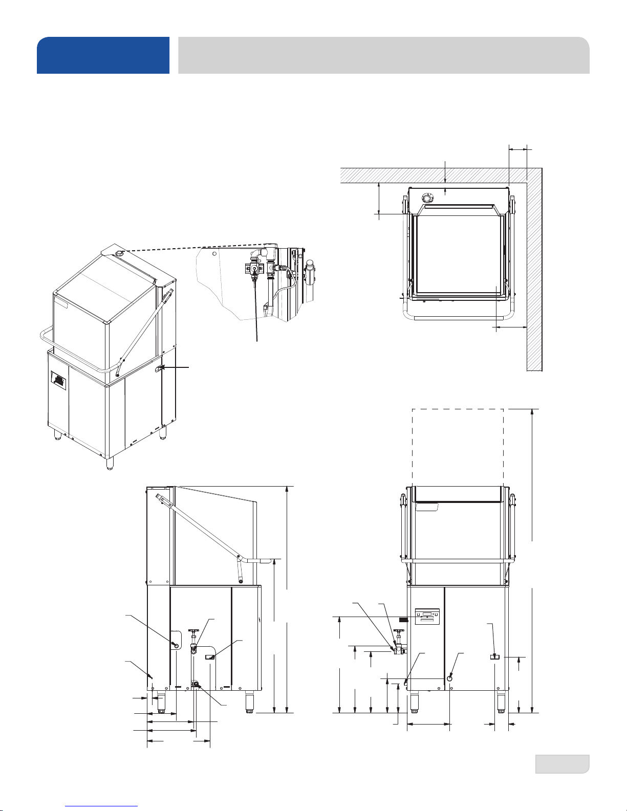
LEGEND
A - Drain Connection (1 1/2" NPT)
B - Water Inlet (1/2" NPT)
(3/4" NPT - DynaTemp S)
C - Electrical Connection (1 1/4" Hole Size)
D - Steam Inlet (3/4" NPT)
E - Steam Outlet (3/4" NPT)
F - Detergent Connection
G - Rinse-aid Connection
All dimensions from the oor can be increased
2" using the machine's adjustable feet.
F
DYNATEMP/NB/S DIMENSIONS
1 7/16"
[37 mm]
8 5/8"
[219 mm]
Distance from
Wall to Rear
Rack Rail
8 7/16"
[214 mm]
Distance from
G
Wall to Right
Rack Rail
5"
[127 mm]
Minimum
E
C
1 3/8
[34 mm]
7 7/8
[200 mm]
13 1/8
[333 mm]
07610-004-29-29-D
16 3/4
[426 mm]
D
12 3/8
[315 mm]
B
A
)
n
e
]
p
m
o
r
m
1
o
7
8
o
5
d
0
h
2
[
it
w
]
m
8
/
m
7
8
4
7
1
3
[
3 5/8
[93 mm]
(
]
m
2
/
m
1
7
0
3
6
5
1
[
]
m
m
1
4
4
4
0
1
[
D
E
A
]
m
8
/
m
5
1
5
5
2
6
[
4
/
3
7
1
]
m
m
2
5
4
[
[197 mm]
8
/
3
6
1
7 3/4
[231 mm]
]
m
m
5
1
4
[
9 1/8
B
C
11 3/8
[287 mm]
2
Page 10
SPECIFICATIONS
3
3
3
/
8
[
8
4
9
m
m
]
1
1
/
2
[
3
7
m
m
]
5
[127 mm]
Minimum
8 5/8
[219 mm]
Distance from
Wall to Rear
Rack Rail
8 7/16
[214 mm]
Distance from
30 3/8
[770 mm]
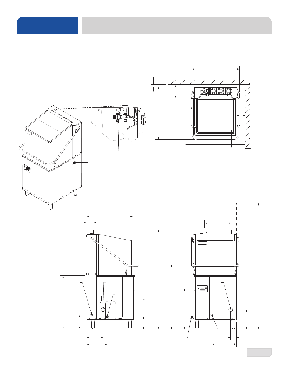
LEGEND
A - Drain Connection (1 1/2" NPT)
B - Water Inlet (1/2" NPT)
C - Electrical Connection (1 1/4" Hole Size)
D - Detergent Connection
E - Rinse-aid Connection
All dimensions from the oor can be increased
2" using the machine's adjustable feet.
D
E
]
m
2
/
m
1
7
1
3
[
]
m
8
/
3
m
9
3
4
3
8
[
Distance from
8 5/8
[219 mm]
Distance from
Wall to Rear
Rack Rail
8 7/16
[214 mm]
Wall to Right
Rack Rail
VER DIMENSIONS
30 3/8
[770 mm]
5
[127 mm]
Minimum
07610-004-29-29-D
4
[102 mm]
]
m
m
4
3
4
6
8
[
10 1/4
[259 mm]
C
Wall to Right
Rack Rail
29 1/2
[750 mm]
]
m
8
/
m
1
3
3
0
6
6
1
[
A
]
]
m
8
/
m
1
1
9
3
2
[
B
m
4
/
m
3
7
7
9
1
[
]
m
8
/
m
1
4
1
4
4
0
1
]
[
m
8
/
5
m
1
5
5
2
6
[
17 1/4
[440 mm]
A
)
n
e
]
p
m
o
r
m
1
o
7
8
o
5
d
0
2
[
ith
w
(
]
m
4
/
m
1
3
2
1
1
3
[
C
3 5/8
12 3/4
[323 mm]
B
15 5/8
[398 mm]
[93 mm]
3
Page 11
SPECIFICATIONS
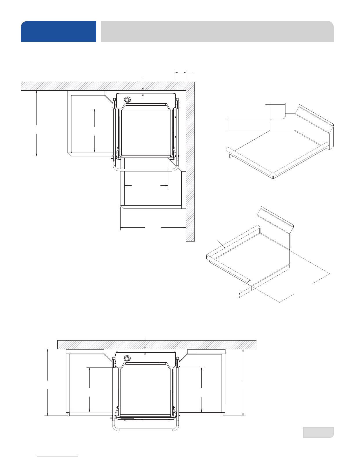
TABLE DIMENSIONS
CORNER INSTALLATION
30"
[762 mm]
20 1/2" [521 mm]
Opening
1 7/16"
[37 mm]
20 1/2" [521 mm]
Opening
5" [127 mm]
Minimum
5”
[127 mm]
For Corner Install instructions,
use this link.
5 3/8”
[137 mm]
30"
[762 mm]
STRAIGHT-THROUGH INSTALLATION
1 7/16"
[37 mm]
30"
[762 mm]
20 1/2" [521 mm]
Opening
1 1/4”
[32 mm]
20 1/2" [521 mm]
Opening
1 3/8”
[35 mm]
[762 mm]
30"
20 1/2”
[521 mm]
Opening
07610-004-29-29-D
4
Page 12

SPECIFICATIONS
NOTICE
OPERATING CAPACITIES
PERFORMANCE/CAPABILITIES
Operating Capacity:
DynaTemp/DynaTemp NB/DynaTemp S
Racks per Hour 57
Dishes per Hour 1425
Glasses per Hour 2052
DynaTemp VER
Racks per Hour 39
Dishes per Hour 975
Glasses per Hour 1404
Minimum Operating Cycle (seconds):
Cycle 1 Wash Time 40
Cycle 2 Wash Time 90
Cycle 3 Wash Time 220
Rinse Time 11
Dwell Time 7
Cycle 1 Total Time 58
Cycle 2 Total Time 108
Cycle 3 Total Time 238
VER Condensate Removal 30
Tank Capacity (gallons/liters):
Wash Tank 8.0/30.3
Rinse Tank 2.0/7.6
Steam Requirements:
Steam Inlet Connection (NPT) 3/4"
Steam Outlet Connection (NPT) 3/4"
Steam Flow Pressure (PSI) 10-30
Consumption @ 15 PSI (lbs/hr) 45
Click here for the Steam Booster manual.
Electrical Loads (as applicable):
WATER REQUIREMENTS
DynaTemp
Wash Temperature (Minimum) 150 °F/66 °C
Rinse Temperature (Minimum) 180 °F/83 °C
Inlet Water Temperature 110 °F/44 °C
Flow Pressure (PSI) 10 ± 2
Water Line Size (NPT) 1/2”
Drain Line Size (NPT) 1 1/2”
DynaTemp NB
Wash Temperature (Minimum) 150 °F/66 °C
Rinse Temperature (Minimum) 180 °F/83 °C
Inlet Water Temperature 180 °F/83 °C
Flow Pressure (PSI) 10 ± 2
Water Line Size (NPT) 1/2”
Drain Line Size (NPT) 1 1/2”
DynaTemp S
Wash Temperature (Minimum) 150 °F/66 °C
Rinse Temperature (Minimum) 180 °F/83 °C
Inlet Water Temperature 180 °F/83 °C
Flow Pressure (PSI) 10 ± 2
Water Line Size (NPT) 1/2”
Drain Line Size (NPT) 1 1/2”
DynaTemp VER
Wash Temperature (Minimum) 150 °F/66 °C
Rinse Temperature (Minimum) 180 °F/83 °C
Inlet Water Temperature 40-90 °F/4.4-32.2 °C
Flow Pressure (PSI) 10 ± 2
Water Line Size (NPT) 3/4”
Drain Line Size (NPT) 1 1/2”
ENERGY SPECIFICATIONS
DynaTemp VER
Latent Heat 6047 Btu/Hr
Sensible Heat 5834 Btu/Hr
Wash Motor HP 1
Wash Heater kW 5.4
Rinse Heater kW 14
Always refer to the machine data plate for specic electrical and water requirements.
The material provided on this page is for reference only and may change without notice.
i
07610-004-29-29-D
5
Page 13
SPECIFICATIONS
NOTICE
Local codes may require more stringent protection than what is displayed here. Always verify with your electrical service
contractor that your circuit protection is adequate and meets all applicable national and local codes. Numbers in this manual
are for reference and may change without notice.
ELECTRICAL REQUIREMENTS
i
DYNATEMP & DYNATEMP VER
Volts Phase Freq
208 1 60 Hz 5.0 A 19.7 A 50.6 A 75.3 A 76.6 A 80.0 A
230 1 60 Hz 5.0 A 21.8 A 55.9 A 82.7 A 84.0 A 90.0 A
208 3 60 Hz 5.0 A 11.4 A 29.2 A 45.6 A 46.9 A 50.0 A
230 3 60 Hz 5.0 A 12.6 A 32.3 A 49.9 A 51.2 A 55.0 A
460 3 60 Hz 1.8 A 6.3 A 16.1 A 24.2 A 24.7 A 30.0 A
DYNATEMP NB
Volts Phase Freq
208 1 60 Hz 5.0 A 19.7 A N/A 24.7 A 26.0 A 30.0 A
On three-phase machines, imbalanced wild leg goes to L3.
Also see the Motor Rotation section.
Wash
Motor
Wash
Motor
Wash
Heater
Wash
Heater
Rinse
Heater
Rinse
Heater
Total Load MCA MOP
Total Load MCA MOP
230 1 60 Hz 5.0 A 21.8 A N/A 26.8 A 28.1 A 30.0 A
208 3 60 Hz 5.0 A 11.4 A N/A 16.4 A 17.7 A 20.0 A
230 3 60 Hz 5.0 A 12.6 A N/A 17.6 A 18.9 A 20.0 A
460 3 60 Hz 1.8 A 6.3 A N/A 8.1 A 8.6 A 15.0 A
DYNATEMP S
Volts Phase Freq
208 1 60 Hz 5.0 A N/A N/A 5.0 A 6.3 A 15.0 A
230 1 60 Hz 5.0 A N/A N/A 5.0 A 6.3 A 15.0 A
208 3 60 Hz 5.0 A N/A N/A 5.0 A 6.3 A 15.0 A
230 3 60 Hz 5.0 A N/A N/A 5.0 A 6.3 A 15.0 A
460 3 60 Hz 1.8 A N/A N/A 1.8 A 2.3 A 15.0 A
Wash
Motor
Wash
Heater
Rinse
Heater
Total Load MCA MOP
07610-004-29-29-D
6
Page 14

INSTALLATION
INSTRUCTIONS
INSPECTION
Do not throw away the
container if damage is
evident!
UNPACKING
LEVELING
Before installing the machine, check the packaging and machine for damage. If the
packaging is damaged, the machine might also be damaged. If there is damage to both
the packaging and machine, do not throw away the packaging. The machine has been
inspected and packed at the factory and is expected to arrive to you in new, undamaged
condition. However, rough handling by carriers or others might result in damage to the
machine while in transit. If so, do not return the machine to the manufacturer; instead,
contact the carrier and ask them to send a representative to the site to inspect the
damage and complete an inspection report. You must contact the carrier within 48
hours of receiving the machine. Also contact the dealer that sold you the machine.
While removing the machine from the packaging, ensure there are no missing parts. If
an item is missing, contact the manufacturer immediately .
The machine must be level in its operating location to prevent
damage during operation and to ensure the best results. The
machine comes with four adjustable bullet feet, which can be
turned using a pair of channel locks (or by hand if the machine can
be raised safely). Ensure the machine is level from side-to-side and
front-to-back before making any connections.
PLUMBING
The plumber MUST ush
the incoming water line!
DRAIN LINE
CONNECTION
Plumbing connections must comply with all applicable local, state, and national
plumbing codes. The plumber is responsible for ensuring that the incoming water line
is thoroughly ushed before connecting it to any component of the machine. It is very
important to remove all foreign debris from the water line that might potentially get
trapped in the valves or cause an obstruction. Any valves that are fouled as a result of
foreign matter left in the water line—and any expenses resulting from this fouling—are
not the responsibility of the manufacturer.
The drains for the models covered in this manual are gravity discharge drains. All
piping from the 1 1/2” FNPT connection on the wash tank must be pitched 1/4” per foot
to the oor or sink drain. All piping from the machine to the drain must be a minimum 1
1/2” NPT and must not be reduced.
There must also be an air-gap between the machine drain line and the oor sink or
drain. The air-gap must be at least 1.5 times the diameter of the drain line. If a grease
trap is required by code, it should have a ow capacity of 5 GPM.
For machines equipped with the Drain Water Tempering option, click here for install
instructions.
07610-004-29-29-D
7
Page 15

INSTALLATION
NOTICE
INSTRUCTIONS
WATER SUPPLY
CONNECTION
A water hardness test
MUST be performed.
i
Take care not to confuse
static pressure with
ow pressure!
Read the Plumbing section on the previous page before proceeding.
Install the water supply line to the machine using copper pipe. A water shut-off valve
should be installed in the water line between the main supply and the machine to
allow access for service.
If water hardness tests at greater than 3 GPG, install the Scaltrol Water Treatment
system (see the Plumbing Options page) into the water line before the machine’s
incoming water connection point. If water hardness tests at 3 GPG or less, install the
water supply line directly to the machine’s incoming water connection point.
The water supply line must be capable of 10 ± 2 PSI “ow” pressure at the recommended
temperature indicated on the data plate.
Do not confuse static pressure with ow pressure. Static pressure is the line pressure
in a “no ow” condition (all valves and services are closed). Flow pressure is the
pressure in the ll line when the ll valve is opened during the cycle.
The manufacturer recommends the installation of a pressure regulating valve (PRV)
in the incoming water line to ensure proper owrate at all times and offers these
devices as options. See the Plumbing Options page. The PRV comes standard on
the DynaTemp VER but ships inside the machine. Click here for install instructions.
STEAM LINE
CONNECTION
i
PLUMBING
CHECK
!
CAUTION
The manufacturer also recommends the installation of a water hammer arrestor in the
incoming water line and offers these devices as options. See the Plumbing Options
page. This prevents line hammer/hydraulic shock—induced by the solenoid valve as
it operates—from causing damage to the equipment.
DynaTemp S comes with lines to connect the source steam. Connect steam lines to
the machine according to all applicable codes. See machine data plate for information
concerning steam ow pressure.
Click here for the Steam Booster manual.
1. Slowly turn on the water supply to the machine after the incoming ll line and drain
line have been installed.
2. Check for any leaks and repair as required.
CAUTION! All leaks must be repaired before placing the machine in operation.
07610-004-29-29-D
8
Page 16
INSTALLATION
INSTRUCTIONS
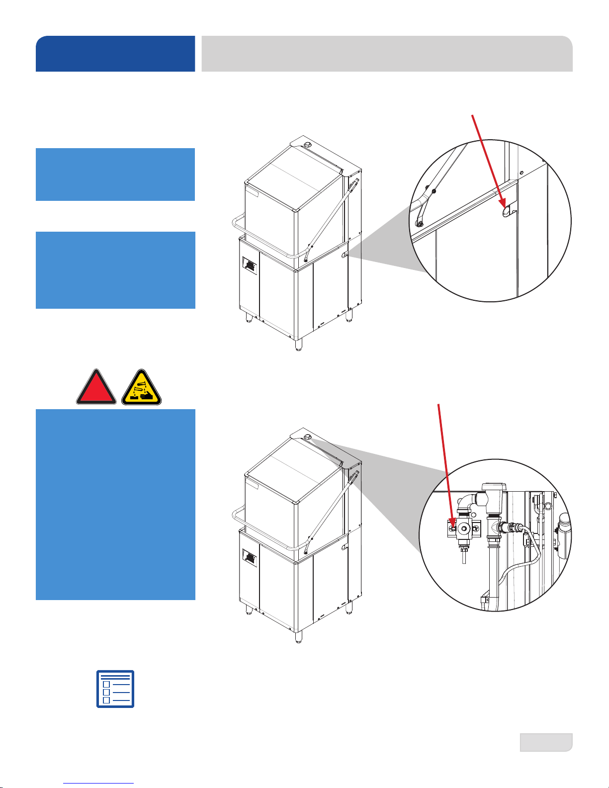
CHEMICAL
CONNECTIONS
Chemical connections
should be made by the
chemical supplier.
Using deionized water or
other aggressive uids
will result in corrosion and
failure of components and
will void the warranty.
!
WARNING
Detergent
Connect detergent by removing the bulkhead tting on the side of the machine and
replacing it with the appropriate dispensing equipment.
Rinse-aid
Connect rinse-aid by removing one of the brass plugs on the side of the rinse
injector and replacing it with the appropriate dispensing equipment.
WARNING! Some of the
chemicals used in
dishwashing may cause
chemical burns if they
come in contact with skin.
Wear protective gear when
handling these chemicals.
If any skin comes in
contact with these
chemicals, immediately
follow the instructions
provided with the
chemicals for treatment.
Dispenser Electrical Connections
The electrical connections for chemical dispensers are made on a fuse block inside
the control box. Click here for a depiction of the fuse block and connection locations.
07610-004-29-29-D
9
Page 17
INSTALLATION
NOTICE
NOTICE
INSTRUCTIONS
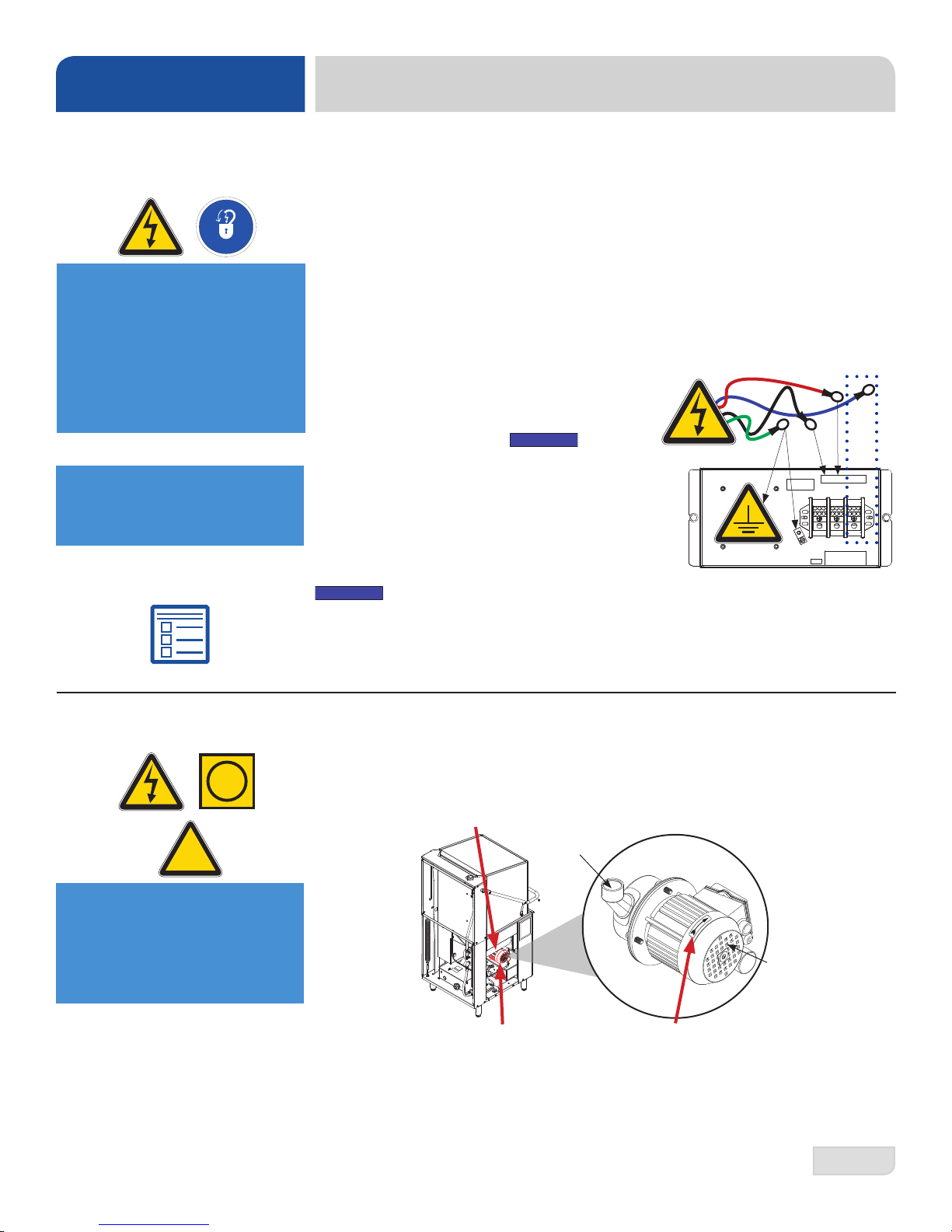
ELECTRICAL POWER
CONNECTIONS
Disconnect electrical
power supplies and
lockout/tagout in
accordance with
appropriate procedures
and codes at the
disconnect switch.
If necessary, see
"Heaters" page for
phase conversion kit.
Electrical and grounding conductors must comply with the applicable portions of the
National Electric Code ANSI/NFPA 70 (latest edition) and/or other electrical codes.
The data plate is located on the left side of the machine. Refer to the data plate for
machine operating requirements, machine voltage, total amperage, and serial number.
1. Open the control box by using a phillips screwdriver to remove the four screws
on the front cover.
2. Install 3/4” conduit into the pre-punched holes in the back of the control box.
3. Route incoming-power wires, and connect to power block and grounding lug.
4. Install the service wires (L3 for 3-Phase) to the appropriate terminals as they are
marked on the terminal block.
3Φ
Imbalanced wild
leg goes to L3.
5. Install the grounding wire into the lug provided.
6. Tighten the connections.
“DE-OX” or similar anti-oxidation agent should be used on all power
connections.
CAUTION! Improperly connecting external devices can cause damage to the
machine and/or electrical infrastructure! Click here for a wiring guide.
L1 L2 L3
GND
MOTOR ROTATION
i
!
CAUTION
CAUTION! On 3-Phase
machines only, correct
pump motor rotation
must be veried
before operation!
07610-004-29-29-D
On 3-Phase machines only, correct pump motor rotation must be veried before
the machine is operated. Failure to do so can result in damage to the machine and
components.
1. Follow the "Filling the Wash Tub" section.
2. Remove the left side panel of the machine.
Pump Volute
Motor Fan
3. Locate the wash pump motor and identify the arrow decal which shows the
correct motor rotation (if no decal is present, correct rotation is away from the
pump volute).
4. Push the Delime Button on the display.
5. Observe the rotation of motor fan and quickly push the Delime Button again.
6. If rotation is incorrect, disconnect electrical power and reverse the L1 and L2
connections at terminal block shown in the section above.
10
Page 18
INSTALLATION
NOTICE
INSTRUCTIONS
VOLTAGE CHECK
!
CAUTION
i
EXHAUST FAN
TIMER
1. Ensure the power switch is in the OFF position and apply power to the machine.
2. Check the incoming power at the terminal block and ensure it corresponds to
the voltage listed on the data plate. If not, contact a qualied service agency to
examine the problem.
CAUTION! Do not run the machine if the voltage is too high or too low (refer to
applicable electrical codes).
3. Shut off the service breaker and mark it as being for the machine.
4. Advise all proper personnel of any problems and of the location of the service
breaker.
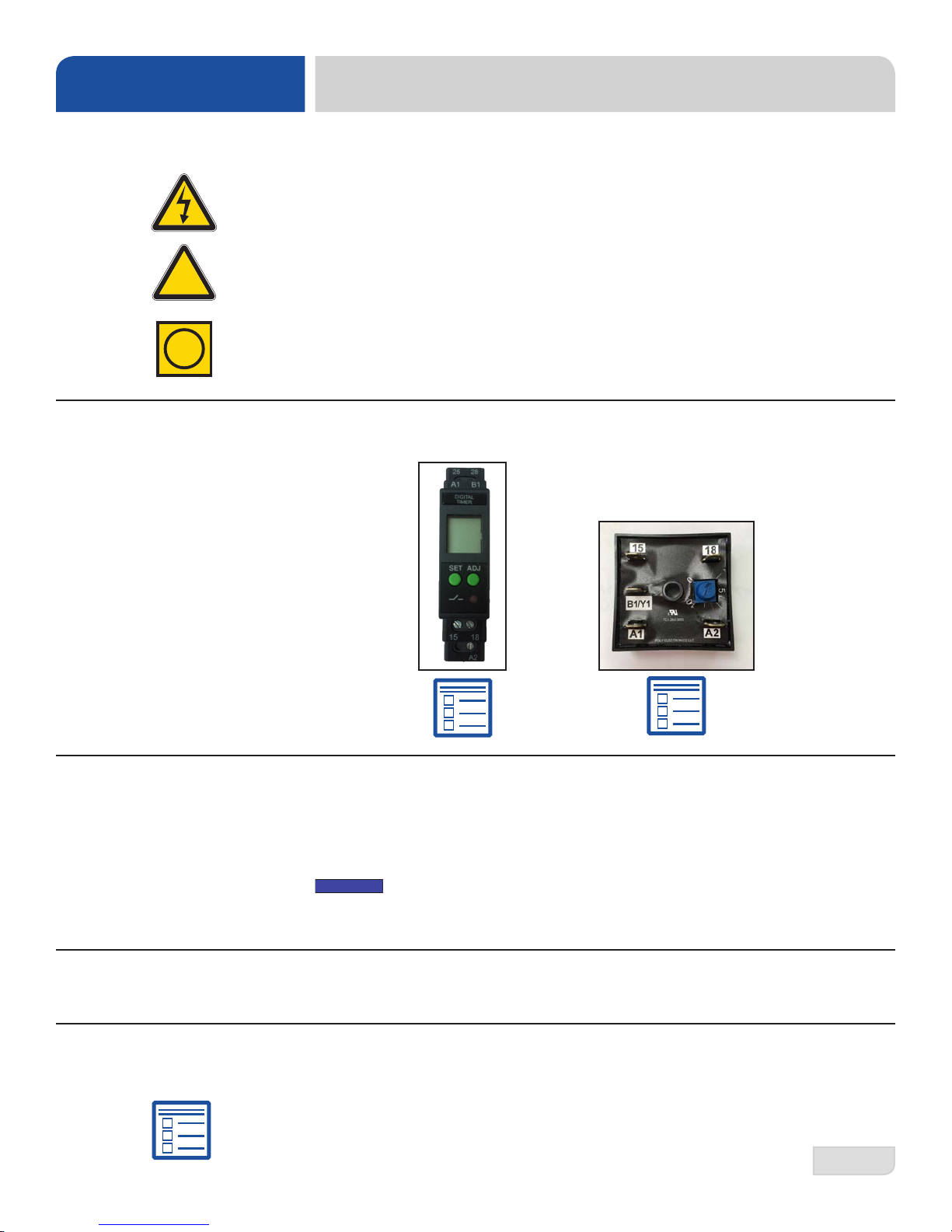
Determine which exhaust fan timer is on the machine and click the instructions icon
below that timer to access programming instructions.
SURROUNDING
AREA
TEMPERATURE
SETPOINTS
CORNER INSTALL/
FALSE PANEL
This is a commercial machine and reaches temperatures that can exceed those
generated by a residential machine. Surrounding countertops, cabinets, ooring, and
subooring must be designed and/or selected with these higher temperatures in
mind.
Any damage to surrounding area caused by heat/moisture to materials that
are not recommended for higher temperatures will not be covered under
warranty or by the manufacturer.
The temperature setpoints on this machine have been set at the factory. They
should only be adjusted by an authorized service agent.
The manufacturer offers an optional False Panel Kit for corner installations.
Click here for corner install and false panel instructions.
DynaTemp False Panel Kit
05700-004-44-38
07610-004-29-29-D
11
Page 19
OPERATION
OPERATING INSTRUCTIONS
PREPARATION
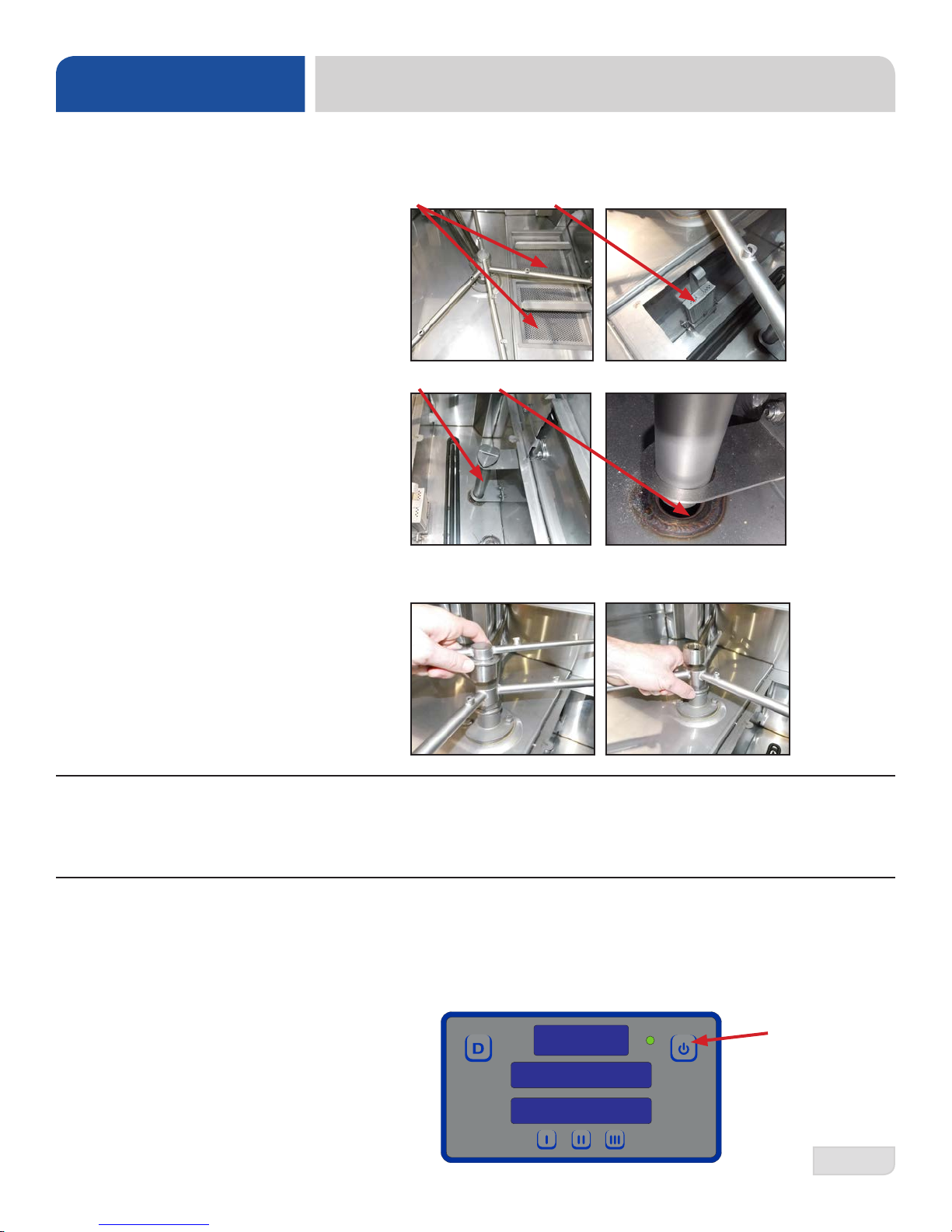
Before operating the machine, verify the following:
1. The pan strainers and suction strainer are in place and are clean.
2. The standpipe and o-ring are installed.
3. The wash and rinse arms are screwed securely into place and the end-caps are
tight. The wash and rinse arms should rotate freely.
POWER UP
FILLING THE
WASH TUB
07610-004-29-29-D
T o energize the machine, turn on the power at the service breaker . The voltage should
have been previously veried as being correct. If not, the voltage will have to be
veried.
Press the Power Button and the display will come on. The machine will ll with water
automatically until the appropriate water level is reached (just below the pan strainers).
The wash tub must be completely lled before operating the wash pump to prevent
damage to components.
Power Button
12
Page 20
OPERATION
OPERATING INSTRUCTIONS
WARE
PREPARATION
DAILY MACHINE
PREPARATION
Proper ware preparation will help ensure good results and fewer re-washes. If not
done properly, ware might not come out clean and the efciency of the machine
will be reduced. Putting unscraped dishes into the machine affects its performance,
so scraps should always be removed from ware before being loaded into a rack.
Pre-rinsing and pre-soaking are good ideas, especially for silverware and casserole
dishes. Place cups and glasses upside-down in racks so they don't hold water during
the cycle. The machine sanitizes as well as cleans. To do this, ware must be properly
prepared before being placed in the machine.
Refer to the “Preparation” section and follow the instructions there. Afterward, ensure
that chemicals are supplied to the machine. If not, contact your chemical supplier.
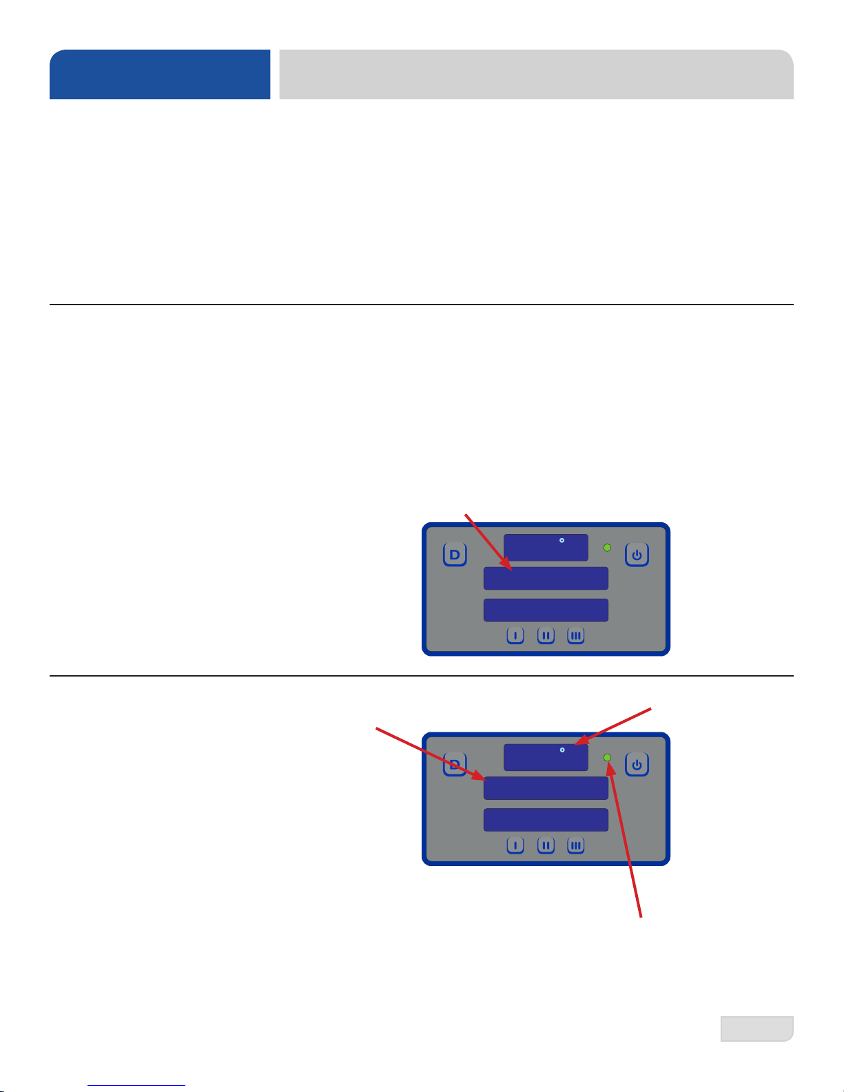
When the machine is rst powered on for the day/shift, wash tank water must reach
the set temperature before being operated:
1. Ensure the door is closed.
2. Press the Power Button.
3. The machine will ll automatically.
4. The display will show “Heating” until wash tank reaches the set temperature.
W ASHING A RACK
OF WARE
125 F
HEATING
CYCLE 1
1. Ensure wash tank temperature has reached the set temperature and the display
shows "Ready."
150 F
READY
CYCLE 1
2. Open the door.
3. Slide a loaded rack of ware into the machine.
4. Close the door. Cycle begins automatically and the cycle light comes on.
5. At the end of the cycle, the cycle light will turn off.
6. Open the door and remove the rack.
07610-004-29-29-D
13
Page 21
OPERATION
OPERATING INSTRUCTIONS
SHUTDOWN &
CLEANING
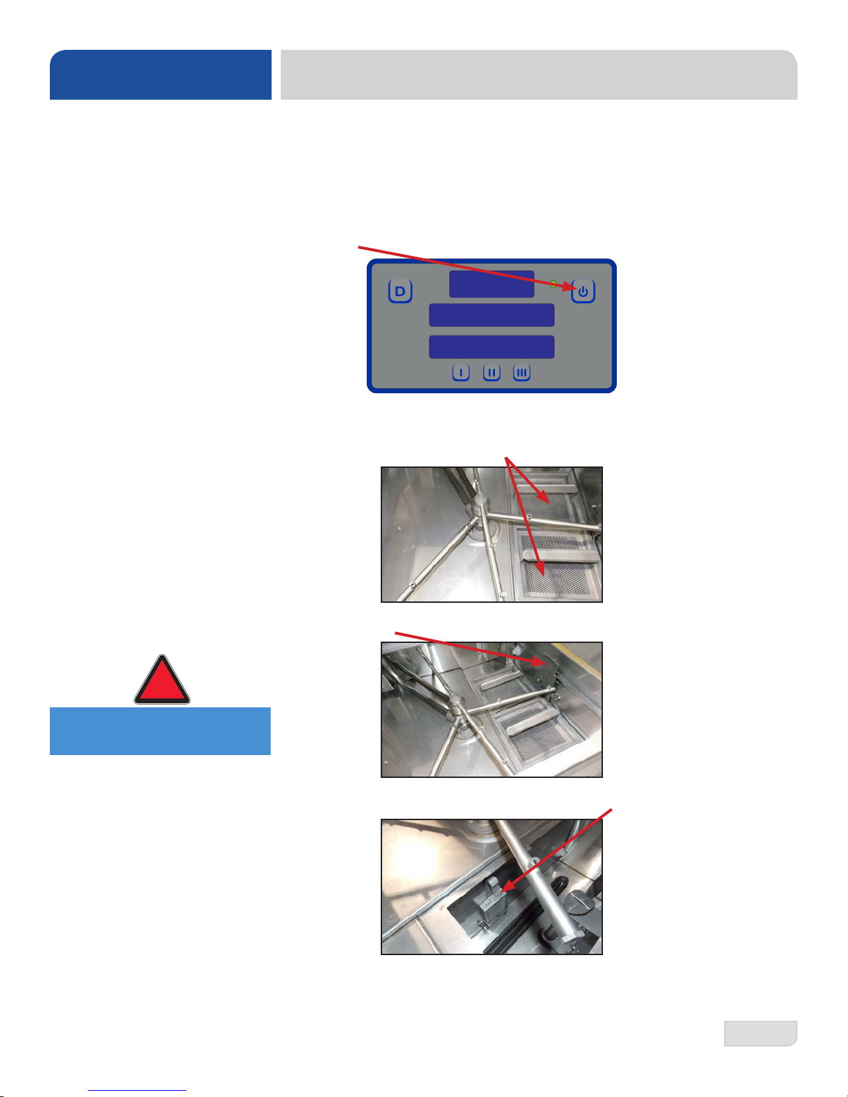
At the end of the day/shift:
1. Close the door.
2. When the machine completes the cycle, turn the machine off by pressing the
Power Button.
3. Open the door.
4. Remove and clean the pan strainers and set aside.
!
WARNING
WARNING! Wash tank
water is hot!
5. Pull the drain handle to the open position and allow the water to drain.
6. Once the wash tub is drained, remove the suction strainer, clean, and set aside.
07610-004-29-29-D
14
Page 22

OPERATION
OPERATING INSTRUCTIONS
SHUTDOWN &
CLEANING
7. Unscrew the wash and rinse arms from their manifolds.
8. Verify the nozzles and arms are free from obstruction. If clogged, remove end-
caps, clean nozzles with a brush, and ush with fresh water.
9. Wipe the inside of the machine out, removing all soil and scraps.
10. Reassemble the wash and rinse arms.
11. Replace the wash and rinse arms in the machine. Ensure the end-caps have
been tightened.
12. Push the drain handle to the closed position.
13. Replace the pan strainers and suction strainer.
14. Leave the door open so the machine can dry.
07610-004-29-29-D
15
Page 23

OPERATION
OPERATING INSTRUCTIONS
DETERGENT
CONTROL
Detergent usage and water hardness are two factors that contribute greatly to how
efciently this machine will operate. Using detergent in the proper amount can
become a source of substantial savings. A qualied water-treatment specialist can
determine what is needed for maximum efciency from the detergent.
1. Hard water greatly affects the performance of the machine, causing the amount
of detergent required for washing to increase. If the machine is installed in
an area with hard water, the manufacturer recommends the installation of the
Scaltrol Water Treatment system.
2. Deposited solids from hard water can cause spotting that will not be removed
with a drying agent. Treated water will reduce this occurence.
3. Treated water might not be suitable for use in other areas of operation and it
might be necessary to install a water treatment system for the water going to the
machine only. Discuss this option with a qualied water treatment specialist.
4. Operators should be properly trained on how much detergent is to be used per
cycle. Meet with a water treatment specialist and chemical supplier to discuss a
complete training program for operators.
5. Chemicals must be provided for proper operation and sanitization and require the
installation of third-party chemical feeders to introduce these chemicals to the
machine. Contact a chemical supplier with any questions.
6. Water temperature is an important factor in ensuring the machine functions
i
properly, and the machine's data plate details what the minimum temperatures
must be for the incoming water supply, the wash tank, and the rinse tank. If
minimum requirements are not met, it's possible that dishes will not be clean or
sanitized.
7. Instruct operators to observe the required temperatures and to report when they
fall below the minimum allowed. A loss of temperature can indicate a larger
problem.
07610-004-29-29-D
16
Page 24

OPERATION
OPERATING INSTRUCTIONS
DELIMING
To maintain the machine at its optimum performance level, lime and corrosion deposits must be removed. The frequency for deliming will be based on water conditions. A deliming solution is available from your chemical supplier. Read and follow
all instructions on the label.
To delime the machine:
1. Disconnect or turn off all chemical feeder equipment.
2. Remove rinse arms and place in sink with deliming solution.
3. Verify the standpipe is in position, turn the machine on, and allow the
machine to complete a ll cycle.
4. Open the door and verify water level is above standpipe. Add deliming
solution per the solution manufacturer’s recommendation (the water capacity
of the tank can be veried on the specication page of this manual).
5. Close the door and push the Delime Button on the display.
07610-004-29-29-D
6. Run the machine for the period of time recommended by the chemical
supplier.
7. Press the Delime Button again and the pump will stop.
8. Open the door and remove the standpipe.
9. Wait ve minutes, then inspect the inside of the machine. If the machine is
not delimed, run again.
10. When clean, drain and rell the machine.
11. Run a cycle to remove residual deliming solution.
12. Replace rinse arms.
13. Drain and rell the machine.
17
Page 25

OPERATION
DISPLAY INSTRUCTIONS
SETTING CYCLES
CHECKING
CYCLE COUNT
GENERAL
Press and release the I Button to set cycle 1.
Press and release the II Button to set cycle 2.
Press and release the III Button to set cycle 3.
While the machine is powered off, press and hold the Power Button. The total cycle
count will display for several seconds, followed by a “power-on” condition.
1. When the machine is rst connected to the power mains, the display will go
through a sequence to show all LEDs are working.
2. The machine will then go into standby mode with the display turned off.
3. Press the Power Button.
4. The display will show “Heating” until the wash tank reaches the set temperature.
Cycle Light
Delime Button
125 F
Power Button
HEATING
CYCLE 1
OPERATIONAL
MESSAGES
Cycle Buttons
5. The display will show “Ready” when the machine is ready to use.
150 F
READY
CYCLE 1
DISPLAY INDICATOR
"Check for open door" Door is open when the machine needs to ll (oat switch is down).
"Filling" Indicates the initial ll after the machine is rst powered on.
"Heating"
"Delime" The Delime Button has been pressed.
"Ready" The machine is not in a cycle and ready for the next load.
"Washing"
"Rinsing"
"Dwelling"
The wash tank and booster have not reached operating
temperature during the machine’s initial heating phase.
The machine is in the wash phase of a cycle with power to the
wash pump.
The machine is in the rinse phase of a cycle with power to the
rinse valve; wash pump is turned off.
The machine is in the dwelling phase of a cycle. Neither wash
pump nor rinse valve are turned on.
07610-004-29-29-D
18
Page 26

MAINTENANCE
!
PREVENTATIVE MAINTENANCE
PREVENTATIVE
MAINTENANCE
WARNING
i
!
CAUTION
CAUTION!
Do NOT beat strainers to
remove debris!
The manufacturer highly recommends that any maintenance and repairs not specically
discussed in this manual be performed only by qualied service personnel.
WARNING! Unqualied personnel performing maintenance on the machine may void the
warranty , lead to larger problems, or cause harm to the operator.
Following the operating and cleaning instructions in this manual will result in the most
efcient results from the machine. As a reminder, here are some steps to take to ensure
the machine is being used the way it was designed to work:
1. Ensure the water temperatures match those listed on the machine data plate. A loss
of temperature can indicate a larger problem.
2. Ensure all strainers are clean and securely in place before operating the machine.
When cleaning out strainers, do NOT beat them on waste cans. Wipe out strainers
with a rag and rinse with water if necessary . Use a toothpick to dislodge any stubborn
debris.
3. Ensure all wash and rinse arms are secure in the machine before operating.
4. Ensure the standpipe is in position before operating.
5. Remove as much soil from dishes by hand as possible before loading into racks.
6. Do not overll racks.
7. Ensure glasses are placed upside-down in the rack.
8. Ensure all chemicals being injected into the machine are at the correct concentrations.
9. Clean the machine at the end of every day/shift per the Shutdown and Cleaning
section of this manual.
10. Follow all safety procedures, whether listed in this manual or put forth by local, state,
or national codes/regulations.
07610-004-29-29-D
19
Page 27

TROUBLESHOOTING
PROGRAMMING
PROGRAMMING
To access programming, the machine should be on and not in cycle.
The programming buttons (Up-arrow, Down-arrow, and Select) are hidden on the
display and are shown below as red outlines. There is a full-size display template at
the end of the manual to help locate the programming buttons.
Factory Setup (Model Selection)
1. Press and hold the I and III Buttons until “Program” starts ashing (2 - 3
seconds).
PROGRAM
2. Press the Select Button.
3. Use the Up-arrow or Down-arrow Button to change the program number to “4.”
PROGRAM
4
4. Press the Select Button.
5. “Program” will ash.
6. Press the Delime Button to exit.
READY
CYCLE 1
150 F
07610-004-29-29-D
20
Page 28

TROUBLESHOOTING
PROGRAMMING
PROGRAMMING
To access programming, the machine should be on and not in cycle.
The programming buttons (Up-arrow, Down-arrow, and Select) are hidden on the
display and are shown below outlined with red dots. There is a full-size display
template at the end of the manual to help locate the programming buttons.
User Setup
1. Press and hold the Up-arrow and Down-arrow Buttons until “Setup” starts
ashing (2 - 3 seconds).
SETUP
2. The display will then change to “Version” and show the rmware versions of the
IO module and PCB, Digital Display.
3. Use the Up-arrow Button to cycle through the categories (will be ashing).
• Language • Wash Offset
• Temperature Scale • Rinse Offset
• Wash Temperature • Boost Offset
• Boost Temperature • Spare Offset
07610-004-29-29-D
LANGUAGE
4. Press the Select Button to choose the category you want to change.
• Regardless of the category, Steps 5 - 7 remain the same.
5. Use the Up-arrow Button to change the options (will be ashing). Numerical
options are shown in the top window.
LANGUAGE
ENGLISH
6. Press the Select Button to accept the changes.
7. Press the Delime Button to exit.
21
Page 29

TROUBLESHOOTING
DISPLAY SHOWS POSSIBLE CAUSES REMEDY
1. Verify incoming water pressure is 10 ± 2 PSI.
“F1 Service needed,”
“No water in Booster”
“F2 Service needed,”
“Check booster
thermostat”
1. Low or no water pressure.
2. Faulty inlet valve or ll relay.
3. Contactor to booster heater not turning off.
4. Faulty temperature input (P12) on IO
module.
5. Faulty temperature probe (T3).
6. Faulty oat switch allows heaters to
operate with no water in tub.
1. Contactor to booster heater not turning off.
2. Faulty temperature input (P12) on IO module.
3. Faulty temperature probe (T3).
2. Verify that ll relay is supplying voltage to ll solenoid.
Replace faulty component.
3. Check for welded contacts. Verify that output from IO
module turns off when above the set temperature.
4. Substitute a 1.2 kΩ resistor for T3, and verify that booster
heater turns off. If not, replace IO module.
5. Verify that the booster-probe resistance is correct with
respect to temperature (see table on pg. 24). If not, replace
T3.
6. Replace oat switch.
1. Check for welded contacts. Verify that output from IO
module turns off when above the set temperature.
2. Substitute a 1.2 kΩ resistor for T3, and verify that booster
heater turns off. If not, replace IO module.
3. Verify that the booster probe resistance is correct with
respect to temperature (see table on pg. 24). If not, replace
T3.
FAULT CODES
“F3 No water in wash
tank,” “Check inlet
water and door”
"F4 Service needed,"
"Check incoming
power"
“F5 Service needed,”
“Check booster
thermostat and high
limit”
1. Malfunction of ll solenoid or ll relay.
2. Door is open, which inhibits ll mode.
3. Faulty door switch.
1. Incoming power not properly connected.
2. L3 is missing (3-phase machines only).
1. Faulty temperature input (P12) on IO
module.
2. Faulty temperature probe (T3).
3. Faulty high-limit switch.
4. Faulty booster heater.
5. Booster-heater contactor not energizing.
1. Replace faulty component.
2. Close door to activate door switch.
3. Replace or adjust door switch.
1. Check connections to heater.
2. Verify that L3 is present and connected properly.
1. Substitute a 1.8 kΩ resistor for T3, and verify that booster
heater turns on. If not, replace IO module.
2. Verify that T3 resistance is consistent with the table on
pg. 24. If not, replace T3.
3. Replace high-limit switch.
4. Check booster heater for proper resistance. Replace if
incorrect.
5. Verify that drive voltage to contactor coil is present
during a call for heat and that contactor closes. If voltage is
present, replace contactor. If voltage is not present, check
wiring.
07610-004-29-29-D
22
Page 30

TROUBLESHOOTING
DISPLAY SHOWS POSSIBLE CAUSES REMEDY
1. Verify incoming water pressure is 10 ± 2 PSI.
1. Low or no water pressure.
2. Verify that ll relay is supplying voltage to ll solenoid.
2. Faulty inlet valve or ll relay.
Replace faulty component.
FAULT CODES
“F6 Service needed,”
“No water in wash tank”
“F7 Service needed,”
“Check wash tank
thermostat”
“F8 No water in wash
tank,” “Check inlet
water and door”
“F9 Service needed,”
“Check incoming
power”
“F10 Service needed,”
“Check wash tank
thermostat and high
limit”
F11 Service needed
–check wash tank
thermostat
3. Contactor to wash heater not turning off.
4. Faulty temperature input (T1) on IO
module.
5. Faulty temperature probe (T1).
6. Faulty oat switch allows heaters to
operate with no water in tub.
1. Contactor to wash heater not turning off.
2. Faulty temperature input (P10) on IO
module.
3. Faulty temperature probe (T1).
1. Malfunction of ll solenoid or ll relay.
2. Door is open, which inhibits ll mode.
3. Faulty door switch.
1. Incoming power not properly connected.
2. L3 is missing (3-phase machines only).
1. Faulty temperature input (T1) on I/O
module.
2. Faulty temperature probe (T1).
3. Faulty high-limit switch.
4. Faulty wash heater.
5. Wash-heater contactor not energizing.
Faulty temperature probe (T1). Replace probe that connects to P10.
3. Check for welded contacts. Verify that output from IO
module turns off when above the set temperature.
4. Substitute a 1.2 kΩ resistor for T1, and verify that wash
heater turns off. If not, replace IO module.
5. Verify that T1 resistance is correct with respect to
temperature (see table on pg. 24). If not, replace T1.
6. Replace oat switch.
1. Check for welded contacts. Verify that output from IO
module turns off when above the set temperature.
2. Substitute a 1.2 kΩ resistor for T1, and verify that wash
heater turns off. If not, replace IO module.
3. Verify that T1 resistance is correct with respect to
temperature (see table on pg. 24). If not, replace T1.
1. Replace faulty solenoid or ll relay.
2. Close door to activate door switch.
3. Replace or adjust door switch.
1. Check connections to heater.
2. Verify that L3 is present and connected properly.
1. Substitute a 1.8 kΩ resistor for T1, and verify that wash
heater turns on. If not, replace I/O module.
2. Verify that T1 resistance is correct with respect to
temperature (see table on pg. 24). If not, replace T1.
3. Replace high-limit switch.
4. Check wash heater for proper resistance. Replace if
incorrect.
5. Verify that drive voltage to contactor coil is present during
a call for heat and that contactor closes. If voltage present,
replace contactor. If voltage not present, check wiring.
07610-004-29-29-D
23
Page 31

TROUBLESHOOTING
DISPLAY SHOWS POSSIBLE CAUSES REMEDY
F12 - Not Used N/A N/A
1. Fully disconnect 6-pin cable at each end, and reconnect
each end until a click is heard.
2. Inspect for broken wire or unseated terminal by gently
pulling on each wire at each end of the cable. Reseat any
loose terminals by inserting it fully into the housing using
long-nosed pliers. Replace cable if broken wire is found.
3. Temporarily substitute a veried good display board, and
check if F13 message recurs. If so, repeat substitution with
a good I/O module.
F13 Communication
error. Check 6-pin
cable
1. Loose connection in 6-pin cable between
display board and I/O module.
2. Faulty 6-pin cable between display board
and I/O module.
3. Faulty communication port on I/O module
or display board.
RESISTANCE-TO-TEMPERATURE VALUES
FAULT CODES
R (kΩ) °F
11.58 69.8
10.37 75.2
9.30 80.6
7.78 89.6
3.05 140.0
2.54 150.8
2.18 159.8
1.58 179.6
1.45 185.0
1.33 190.4
1.16 199.4
0.96 212.0
07610-004-29-29-D
24
Page 32

!
TROUBLESHOOTING
WARNING! Inspection, testing, and repair of electrical equipment should only be performed by a
WARNING
PROBLEM POSSIBLE CAUSES REMEDY
qualied service technician. Many of the tests require that the machine have power to it and live
electrical components be exposed. USE EXTREME CAUTION WHEN TESTING THE MACHINE.
COMMON PROBLEMS
Digital display does not
illuminate after power
button is pressed.
Machine does not ll when
machine is powered on
(door must be closed.)
Machine will not begin
wash cycle upon closing
the door.
Machine continuously
washes.
1. Service breaker tripped.
2. Machine not connected to power
source.
3. Faulty power source.
1. Tank already full.
2. Faulty rinse solenoid valve.
3. Faulty door switch.
4. Faulty oat switch.
1. Wash motor faulty/damaged.
2. Wash motor contactor faulty.
3. Timer Module is faulty.
4. I/O Module is faulty.
1. Machine is in Delime mode,
which will be indicated in the
display.
2. Timer Module is faulty.
1. Reset breaker. If it trips, again, contact an electrician to verify
the amp draw of the machine.
2. Verify that the machine has been properly connected to the
power source.
3. Verify the wiring to the breaker switch.
1. N/A
2. Repair or replace valve as required.
3. Verify the wiring of the switch; if correct, replace switch.
4. Verify the wiring of both oat switches; if correct, replace
switch.
1. Verify that the wash motor is receiving power; if so, replace the
motor.
2. Verify that contactor energizes; if so, then, with contactor
energized, verify continuity across poles; if contacts are open,
then replace the contactor.
3. Verify that module is receiving power (red LED is on); if so,
replace it.
4. Verify that module is receiving power (green LEDs are on); if
so, replace it.
1. Turn off Delime mode by pressing Delime key.
2. Verify that module is receiving power (green LEDs are on); if
so, replace it.
1. Faulty heater element.
Wash or rinse heater does
not work.
Machine lls slowly and/or
the rinse is weak.
07610-004-29-29-D
2. Faulty heater contactor.
3. Faulty temperature probe (T1wash tank, T3-rinse tank).
1. Clogged or obstructed rinse arms.
2. Low incoming water pressure.
3. Y-strainer is clogged
1. Verify that element has very low resistance (< 20 Ω) across
terminals. If high resistance or open, replace the heater.
2. Verify that contactor energizes; if so, then, with contactor
energized, verify continuity across poles; if contacts are open,
then replace the contactor.
3. Measure probe’s resistance with ohmmeter, which should
be ~10 kΩ at 77°F. Replace probe is much different than this
value.
Reference: resistances at 70°F & 85°F are ~11.9 kΩ & 7.4 kΩ,
respectively.
1. Remove and clean the rinse arms.
2. Adjust water-pressure regulator to 10 ± 2 PSI.
3. Clean Y-strainer.
25
Page 33

TROUBLESHOOTING
!
WARNING! Inspection, testing, and repair of electrical equipment should only be performed by a
WARNING
PROBLEM POSSIBLE CAUSES REMEDY
Rinse water is heated,
but not reaching
required temperature.
Incorrect water
pressure displayed
during Fill or Rinse
modes.
Wash water is not
reaching required
temperature.
Doors will not close
completely.
Water leaks at the
wash pump.
qualied service technician. Many of the tests require that the machine have power to it and live
electrical components be exposed. USE EXTREME CAUTION WHEN TESTING THE MACHINE.
1. Faulty rinse heater.
2. Faulty temperature probe (T2- rinse
injector, T3-rinse tank).
3. I/O Module is faulty.
1. Water turned off or disconnected.
2. Pressure sensor disconnected.
3. Pressure sensor defective.
1. Faulty wash heater.
2. Faulty temperature probe (T1).
3. I/O Module is faulty.
1. Improper spring tension.
2. Obstruction in door roller channel.
1. Wash pump seal defective.
2. Petcock or pump drain (if equipped)
not shut/tight.
1. Verify that element has very low resistance (< 20 Ω) across
terminals. If high resistance or open, replace the heater.
2. Measure probe’s resistance with ohmmeter, which should
be ~10 kΩ at 77°F. Replace probe is much different than this
value.
Reference: resistances at 70°F & 85°F are ~11.9 kΩ & 7.4 kΩ,
respectively.
3. Verify that module is receiving power (green LEDs are on); if
so, replace it.
1. Ensure water is connected & turn on valve.
2. Verify connection to I/O Module at P9.
3. Verify output (P9, WHT wire to BLK wire) to be ~1 VDC at 10 ±
2 PSI. If not, then replace pressure sensor.
1. Verify that element has very low resistance (< 20 Ω) across
terminals. If high resistance or open, replace the heater.
2. Measure probe’s resistance with ohmmeter, which should
be ~10 kΩ at 77°F. Replace probe is much different than this
value.
Reference: resistances at 70°F & 85°F are ~11.9 kΩ & 7.4 kΩ,
respectively.
3. Verify that module is receiving power (green LEDs are on); if
so, replace it.
1. Adjust spring tension to desired stiffness by loosening (not
removing) spring bolt nuts near bottom of machine, and
adjusting the tension. Tighten nuts back when done.
2. Remove the obstruction.
1. Replace the seal.
2. Close or tighten.
COMMON PROBLEMS
3. Loose hoses (hose clamps) on the
wash pump.
1. Defective rinse solenoid.
Will not rinse during the
cycle.
Dishes are not coming
clean.
07610-004-29-29-D
2. Timer Module is faulty.
3. No incoming water pressure.
4. Machine temperatures are below
minimum requirements.
1. Machine temperatures are below
minimum requirements.
2. No detergent or too much detergent.
3. Solid dispenser canister is empty.
3. Tighten the hose clamps.
1. Repair or replace the rinse solenoid.
2. Verify that module is receiving power (green LEDs are on); if
so, replace it.
3. Verify 10 ± 2 PSI water pressure to the machine.
4. Verify that incoming water, rinse water, and wash water match
the required temperatures as listed on the machine data plate.
1. Verify that incoming water, rinse water, and wash water match
the required temperatures as listed on the machine data plate.
2. Adjust detergent concentration as required for the amount of
water held by the machine.
3. Replace the canister.
26
Page 34

PARTS
Control Box shown with cover (05700-004-27-52) removed.
4 5 6
2
3
1
CONTROL BOX
7
8 9
11
INPUT L1
(EXTERNAL)
WARNING: DISCONNECT POWER TO MACHINE BEFORE SERVICING
EXHAUST FAN
CONSTANT VOLTAGE
CONTROL
MAXIMUM LOAD
LIVE WHEN MACHINE
AC
1 AMP , 240/120 V
POWER SWITCH IS ON
OUTPUT TO
FUSE: 3 AMP SLOW-ACTING
EXT. RELAY
L1 OUT
CONNECTION
L2 OUT
RINSE-AID DISPENSER
CONNECTION
LIVE WHEN RINSE
VALVE IS OPEN
FUSE: 3 AMP SLOW-ACTING
L1 OUT
L2 OUT
DETERGENT
DISPENSER
CONNECTION
LIVE WHEN WASH
PUMP MOTOR IS ON
FUSE: 3 AMP SLOW-ACTING
L1 OUT
L2 OUT
12
13 1410
Fuses
208/230 V or 460 V
WARNING: DISCONNECT POWER TO MACHINE BEFORE SERVICING
CONSTANT VOLTAGE
CONNECTION
LIVE WHEN MACHINE
AC
POWER SWITCH IS ON
OUTPUT TO
FUSE: 3 AMP SLOW-ACTING
EXT. RELAY
L1 OUT
L2 OUT
INPUT L1
(EXTERNAL)
EXHAUST FAN
CONTROL
MAXIMUM LOAD
1 AMP , 240/120 V
Fuse,1 A, Fast-acting
05999-004-47-87
Littelfuse P/N - 0312001.HXP
Qty - 2 (2 per output)
L2 OUT
DETERGENT
DISPENSER
CONNECTION
LIVE WHEN WASH
PUMP MOTOR IS ON
FUSE: 3 AMP SLOW-ACTING
L1 OUT
L2 OUT
RINSE-AID DISPENSER
CONNECTION
LIVE WHEN RINSE
VALVE IS OPEN
FUSE: 3 AMP SLOW-ACTING
L1 OUT
Fuse, 3 A, Slow-acting
05999-004-44-34
Littelfuse P/N - 0313003.HXP
Qty - 6 (2 per output)
EXHAUST FAN
CONTROL
MAXIMUM LOAD
1 AMP , 240/120 V
INPUT L1
(EXTERNAL)
Fuse,1 A, Fast-acting
05999-004-47-87
Littelfuse P/N - 0312001.HXP
Qty - 2 (2 per output)
WARNING: DISCONNECT POWER TO MACHINE BEFORE SERVICING
CONSTANT VOLTAGE
CONNECTION
LIVE WHEN MACHINE
AC
POWER SWITCH IS ON
FUSE: 200 mA SLOW-ACTING
OUTPUT TO
EXT. RELAY
240 VAC OUT
RINSE-AID DISPENSER
CONNECTION
LIVE WHEN RINSE
VALVE IS OPEN
FUSE: 200 mA SLOW-ACTING
240 VAC OUT
DETERGENT
DISPENSER
CONNECTION
LIVE WHEN WASH
PUMP MOTOR IS ON
FUSE: 200 mA SLOW-ACTING
240 VAC OUT
Fuse, 200 mA, Slow-acting
05999-004-44-33
Littelfuse P/N - 0313.200HXP
Qty - 6 (2 per output)
07610-004-29-29-D
27
Page 35

PARTS
ITEM QTY DESCRIPTION PART NUMBER
1 1 Timer, Universal 05945-003-75-23
2 2 Nut, Conduit Black Nylon 3/4" 05975-003-81-29
3 1 Bracket, Fuse Strip 05700-002-42-03
4 1 Fitting 05975-011-65-51
5 2 Fitting, 3/4" 90° Twist HFC 05975-004-19-42
6 2 Relay 05945-111-47-51
7 1 Fitting 05975-011-59-50
8 2 Contactor, 4-Pole 05945-004-43-74
9 12 Screw, 10-32 x 1/2" 05305-011-44-52
CONTROL BOX
10 1
11 1 Fuse Holder, 6-Pole 05920-002-42-13
12 1 Fuse Holder, 2-Pole 05920-401-03-14
13 1 Contactor, 30 A 240 V 05945-002-74-20
14 1 Exhaust Fan Timer, One-Shot 05945-004-34-92
14a 1 Din Rail, One-Shot Timer (Not Shown) 05935-004-47-77
14b 1 Screw, Phillips Pan Washer (Not Shown) 05305-004-47-78
15 1 Transformer, 460 V Machine Only (Not Shown) 05950-111-65-93
15a 1 Fuse Holder, Single, 460 V Machine Only (Not Shown) 05920-011-72-89
15b 1 Fuse, 1 A, Bussman P/N FNQ-R-1, 460 V Machine Only (Not Shown) 05920-002-67-23
16 1
17 1
I/O Module 05945-004-47-81
I/O Module Kit (Not Shown) 06401-004-55-93
Pump Contactor
Overload, 4NK0AKY 1.7-2.6
, 460 V Machine Only (Not Shown) 05945-002-65-00
, 460 V Machine Only (Not Shown) 05945-002-65-02
07610-004-29-29-D
28
Page 36

PARTS
HOOD
ITEM QTY DESCRIPTION PART NUMBER
1 1 Hood 05700-004-20-68
2 4 Pin, Clevis 5/16" x 1 1/4" 05315-004-07-24
3 2 Roller, Bottom Hood Lateral 09330-004-07-30
4 2 Roller, Bottom Rear 09330-004-07-29
5 1 Door Stop Block (Not Shown) 05700-004-41-95
07610-004-29-29-D
21 3
4
2
29
Page 37

PARTS
CANTILEVER ARM
3c
3d
3d
3a
3e
3b
9
3
2
1
10
8
4
5
6
7
11
12
13
15
14
16
07610-004-29-29-D
17
18
9
19
30
Page 38

PARTS
ITEM QTY DESCRIPTION PART NUMBER
1 Pivot, Cantilever Arm Right 09515-004-25-38
1
1 Pivot, Cantilever Arm Left 09515-004-25-91
2 2 Bushing, Door Pivot Outer 09330-004-26-71
3 2 Y oke Assembly 05700-004-54-74
3a 1 Cotter Pin 05315-207-01-00
3b 1 Yoke 05700-004-97-94
3c 1 Clevis Pin, 5/16” x 1 3/8” 05315-700-01-00
3d 2 Nylon Washer 05311-369-03-00
3e 1 Bushing 03120-100-03-00
4 2 Nut, Hex Coupling 3/8-16 05310-004-26-85
5 2 Bushing, Door Pivot Inner 09330-004-25-63
6 2 Bolt, Hex 3/8-16 x 1 1/4" 05305-276-10-00
CANTILEVER ARM
7 2 Spring Link 05700-004-26-81
8 2 Spring Pin, 1/4" DIA x 1 1/4" Long 05315-407-06-00
9 6 Nut, Hex 3/8-16 SS 05310-276-01-00
10 1 Cantilever Arm 05700-004-20-70
11 2 Link, Hood to Handle 05700-004-20-69
12 2 Standoff, Door Pivot 05700-004-22-75
13 2 Screw, 1/4-20 x 1 1/2" Hex Head 05305-274-23-00
14 2 Locknut, 1/4-20 Low Prole with Nylon Insert 05310-374-02-00
15 4 Washer, SS 1/4-20 ID 05311-174-01-00
16 2 Springs, Cantilever 05340-004-33-86
17 2 Bolt, Cantilever Hang Eye 05306-956-05-00
18 4 Washer, Impeller 3/8" Flat SS 05311-176-02-00
19 2 Locknut, 3/8-16 with Nylon Insert 05310-011-72-55
07610-004-29-29-D
31
Page 39

PARTS
TUB
6
7
8
9
10
11
12
13
14
5
15
4
16
3
2
21
17
18
1
07610-004-29-29-D
19
20
32
Page 40

PARTS
ITEM QTY DESCRIPTION PART NUMBER
1 1 Wash Motor See Wash Motors pg.
2 1 Wash Lower Manifold Nipple 05700-021-34-84
3 2 Clamp 04730-719-18-00
4 1 Discharge Hose 05700-011-88-24
5 1 Lower Wash Manifold 05700-031-46-00
6 2 Strainer 05700-004-26-21
7 1 Standpipe Bracket 05700-004-26-24
8 1 Standpipe 05700-001-25-69
9 1 Suction Strainer 05700-001-22-23
10 1 Standpipe Lift Handle 05700-004-26-23
11 1 Standpipe Support 05700-001-27-55
12 1 Suction Strainer Bracket 05700-001-22-24
13 1 Dual Float Switch 06680-121-70-71
TUB
14 1 O-ring 05330-400-05-00
15 1 Thermostat 05930-004-33-12
16 1 Probe Fitting 05310-924-02-05
17
18 1 Wash Tank Heater Cover 05700-031-47-57
19 1 Wash Heater Gasket 05330-011-47-79
20 1 Wash Heater 04540-121-47-39
21 1 Thermostat Bracket 05700-004-36-37
1 Thermistor Probe 06685-004-17-26
1 Plug (NB Only) (Not Shown) 05700-004-47-32
07610-004-29-29-D
33
Page 41

PARTS
STEAM TUB
6
7
14
8
10
11
13
15
16
9
12
5
4
3
07610-004-29-29-D
2
1
17
18
19
34
Page 42

PARTS
ITEM QTY DESCRIPTION PART NUMBER
1 1 Wash Motor See Wash Motors
2 1 Wash Lower Manifold Nipple 05700-021-34-84
3 2 Clamp 04730-719-18-00
4 1 Discharge Hose 05700-011-88-24
5 1 Lower Wash Manifold 05700-031-46-00
6 2 Strainer 05700-004-26-21
7 1 Standpipe Bracket 05700-004-26-24
8 1 Standpipe 05700-001-25-69
9 1 Suction Strainer 05700-001-22-23
10 1 Standpipe Lift Handle 05700-004-26-23
11 1 Standpipe Support 05700-001-27-55
12 1 Suction Strainer Bracket 05700-001-22-24
13 1 Dual Float Switch 06680-121-70-71
STEAM TUB
14 1 O-ring 05330-400-05-00
15 1 Steam Coil See "Steam Coil" page.
16 1 Tub Front, DynaTemp Steam 05700-004-32-87
17 1 Probe Fitting 05310-924-02-05
18 1 Thermistor Probe 06685-004-17-26
19 1 Wash Tank Heater Cover 05700-031-47-57
07610-004-29-29-D
35
Page 43

PARTS
STEAM COIL
2
1
3
8
7
4
6
ITEM QTY DESCRIPTION PART NUMBER
Complete Steam Coil Assembly 05700-004-34-98
1 1 Steam Coil Weldment 05700-004-34-97
2 1 Stand C, Steam Coil Support 05700-002-08-52
3 1 Stand D, Steam Coil Support 05700-002-08-53
4 4 Gasket, Steam Coil 05700-001-17-86
5 2 Washer, Steam Coil 05700-001-17-87
5
6 2 Adapter, Steam Coil Nut 05310-011-17-85
7 1 Stand A, Steam Coil Support 05700-002-08-50
8 1 Stand B, Steam Coil Support 05700-002-08-51
07610-004-29-29-D
36
Page 44

PARTS
NOTICE
Punch-outs are
provided on both
panels, to be used
if necessary during
installation.
4
FRAME
1
2
3
10
6
7
5
ITEM QTY DESCRIPTION PART NUMBER
1 1 Panel, Right 05700-004-20-80
2 1 Panel, Front 05700-004-10-02
3 1 Panel, Control 05700-004-27-88
4 4 Bullet Foot 05340-004-14-99
5 1 Panel, Left 05700-004-20-83
6 4 Nut, Thumb, 6-32 Nylon 05310-002-83-12
7 1 PCB, Digital Display 05945-004-52-53
8 4 Spacer, Unthreaded, 9/32" Nylon 05975-004-47-89
Complete Display Assembly
05700-004-56-49
8
9
9 1 Panel and Membrane Switch Assembly 05700-004-58-72
10 1 Communication Cable, Display 05700-004-33-64
07610-004-29-29-D
37
Page 45

PARTS
WASH & RINSE ARMS
1
8
2
5
3
11
4
6
10
7
9
07610-004-29-29-D
38
Page 46

PARTS
ITEM QTY DESCRIPTION PART NUMBER
1 1 Wash Manifold 05700-004-28-58
2 1 Rinse Manifold 05700-004-26-07
3* 2 Retaining Ring, Rinse Head Bushing 05340-112-01-11
4* 2 Bearing Assembly, Rinse Arm 05700-004-54-71
5 4 End-cap, Rinse Arm 05700-004-34-62
WASH & RINSE ARMS
6 2
7 2
8 2 Wash Arm Bearing Assembly 05700-021-35-97
9 1 End-cap, Wash Arm 05700-011-35-92
10 1 Lower Wash Manifold 05700-031-46-01
11 1 O-ring (Not Shown) 05330-111-35-15
Complete Rinse Arm Assembly 05700-004-32-58
Rinse Arm 05700-004-27-62
Complete Wash Arm Assembly 05700-004-32-59
Wash Arm 05700-004-24-81
*Rinse Arm Bearing Kit
(Includes items 3 and 4)
06401-004-57-50
07610-004-29-29-D
39
Page 47

PARTS
!
RINSE TANK
Complete Assemblies
208-230 V, 14 kW 70
460 V, 14 kW 70
◦
◦
Rise - 05700-004-43-33
Rise - 05700-004-53-22
CAUTION
CAUTION! DynaTemp & DynaTemp
VER machines with serial numbers
before 18B354991 have the rinse
tank on the next page.
ITEM QTY DESCRIPTION PART NUMBER
1 1 Tank, Rinse 05700-004-50-86
2 1 Heater, Rinse See "Heaters" page.
3 6 Lockwasher, Split 5/16” 05311-275-01-00
4 1 Fitting, 1/4”, Brass Nut/Sleeve 05310-924-02-05
5 1 Gasket, Rinse Heater 05330-200-02-70
6 6 Nut, Hex 5/16-18 05310-275-01-00
7 1 Decal, Warning-Disconnect Power 09905-100-75-93
8 1 Cover, Heater 05700-004-51-34
9 2 Screw 05305-004-27-82
10 1 Thermostat, High-limit 05930-004-33-12
11 1 Bracket, High-limit Thermostat 05700-004-36-84
12 2 Nut, 1/4-20 05310-004-23-96
13 4 Washer, 1/4-20 05311-174-01-00
14 4 Nut, Lock 1/4-20 Hex with Nylon Insert 05310-374-01-00
15 1 Clamp, Wire 1/8", P-clip 05975-601-10-15
16 1 Cover, Booster, Common, Door 05700-004-52-21
17 1 Washer, Flat 05311-173-02-00
18 1 Nut, Hex 8-32, Locking 05310-272-02-00
19 1 Plug, 1/4", Brass (Not Shown) 04730-209-01-00
07610-004-29-29-D
40
Page 48

PARTS
!
RINSE TANK
Complete Rinse T ank Assembly*
05700-002-29-36
4
CAUTION! DynaTemp & DynaTemp
CAUTION
ITEM QTY DESCRIPTION PART NUMBER
1 1 Rinse Tank 05700-004-47-07
VER machines with serial numbers
after 18B354991 have the rinse tank
on the previous page.
5
6
7
10
See "Heaters" page.
9
3
11
8
2
1
2 2 Locknut, 10-24 with Nylon Insert 05310-373-01-00
3 2 Washer, #10 Flat 05311-173-01-00
4 1 Decal, Warning - Disconnect Power 09905-100-75-93
5 1 Cover, Rinse Tank 05700-004-46-81
6 1 Thermostat, High-Limit 05930-004-33-12
7 1 Thermostat Bracket 05700-004-36-84
8 1 Gasket, Rinse Heater 05330-200-02-70
9 1 Fitting, 1/4" Imperial Brass 05310-924-02-05
10 1 Thermistor Probe 06685-004-34-58
11 1 Fitting, Thermostat 05700-001-23-96
*Does not include items 6 and 7, which can be ordered together using P/N 06401-004-39-09.
07610-004-29-29-D
41
Page 49

PARTS
HEATERS
Wash Heater
Rinse Heater
The models covered in this manual come supplied with various heaters, depending on the characteristics of the machine.
To ensure you order the correct heater for the model you are servicing, please refer to the following tables:
MODEL VOLTS Hz PHASE WASH HEATER RINSE HEATER
DynaTemp/VER 208 60 1 04540-121-47-39 04540-121-63-38
DynaTemp/VER 208 60 3 04540-121-47-39 04540-121-63-38
DynaTemp/VER 230 60 1 04540-121-47-39 04540-121-63-38
DynaTemp/VER 230 60 3 04540-121-47-39 04540-121-63-38
DynaTemp/VER 460 60 3 04540-121-65-99 04540-121-63-39
MODEL VOLTS
DynaTemp NB 208 60 1 04540-121-47-39
DynaTemp NB 208 60 3 04540-121-47-39
DynaTemp NB 230 60 1 04540-121-47-39
DynaTemp NB 230 60 3 04540-121-47-39
DynaTemp NB 460 60 3 04540-121-65-99
Hz PHASE
WASH HEATER
07610-004-29-29-D
Heater Phase Conversion Kit
06401-004-00-22
42
Page 50

PARTS
NOTICE
MOTORS
Complete Assemblies
(See next page for parts.)
See Motor
Rotation section.
The models covered in this manual come supplied with various wash motor assemblies (a wash motor assembly includes
the wash motor and the pump end), depending on the characteristics of the machine. To ensure you order the correct
wash motor assembly for the model you are servicing, please refer to the following table:
MODEL VOLTS Hz PHASE WASH MOTOR ASSEMBLY
All 208 60 1 06105-004-24-80
All 208 60 3 06105-004-24-80
All 230 60 1 06105-004-24-80
All 230 60 3 06105-004-24-80
All 460 60 3 06105-121-64-21
1
Use P/N 06105-004-32-04 to order the motor only.
2
Use P/N 06105-002-62-71 to order the motor only.
When servicing a wash motor, it is important to refer to the wiring schematic found on the motor to ensure the motor is wired correctly.
Different manufacturers of motors might not use the same wire color codes and your new motor might not connect using the same
wires. Always refer to the wiring diagrams on the motor you are installing. If the motor you are installing has had the schematic
removed, contact the manufacturer immediately for technical support.
1
1
1
1
2
07610-004-29-29-D
43
Page 51

PARTS
MOTORS
Parts
(See previous page for complete assemblies.)
1
2
3
4
5
6
7
The models covered in this manual come supplied with various wash motors (see previous page), depending on the
characteristics of the machine. To ensure you order the correct parts for the model you are servicing, please refer to the
following table:
ITEM QTY DESCRIPTION PART NUMBER
1
2
3
4
5
6 1 Pump Casing 208/230 V 05700-002-85-01
7 1 Case Capscrew, 208/230 V 05305-002-81-88
1 Seal Plate, 208/230 V 05700-002-81-87
1 Seal Plate, 460 V 05700-002-06-22
1 Case O-ring, 208/230 V 05330-002-81-83
1 Case O-ring, 460 V 05330-002-87-02
1 Mechanical Seal, 208/230 V 05330-002-34-22
1 Mechanical Seal, 460 V 05330-002-87-16
1 Impeller Assembly, 208/230 V 05700-002-81-86
1 Impeller Assembly, 460 V 05700-002-06-19
1 Shim Kit, 208/230 V 05700-002-82-58
1 Shaft Adapter, 460 V 05700-011-95-19
07610-004-29-29-D
44
Page 52

PARTS
PLUMBING
Top View
Injector/Vacuum Breaker
Goes to top
connection on
rinse tank.
To order complete assemblies:
Complete Plumbing Assembly
05700-004-52-71
(Everything above
except item 22.)
Goes to bottom
connection on
rinse tank.
Rinse Injector Plumbing
05700-004-28-49
Rinse Tank Out Plumbing
05700-004-52-66
(Includes 05700-004-28-49.)
Rinse Tank In Plumbing
05700-004-52-70
07610-004-29-29-D
45
Page 53

NOTICE
PARTS
ITEM QTY DESCRIPTION PART NUMBER
1 1 Vacuum Breaker, 1/2" Brass 04820-003-06-13
2 2 Elbow, 90-Degree 1/2" Street Brass 04730-206-08-00
3 1 Tee 04730-002-22-56
4 3 Nipple, 1/2" Close Brass 04730-207-15-00
5 1 Gasket, Rinse Manifold 05330-003-75-91
6 1 Pressure Transducer 05945-004-17-01
7 3 Plug, 1/8" NPT Brass 04730-209-07-37
8 1 Elbow, 90-Degree 1/4" x 1/4" 04730-003-77-83
9 2 Screw, 1/4-20 x 1" 05305-011-81-58
10 1 Injector, Rinse Manifold 05700-004-26-98
11 1 Red Hose, 1/2" x 28" 05700-004-31-75
12 2 Tee, 1/2" Brass 04730-211-27-00
13 1 Thermistor Probe 06685-004-34-58
PLUMBING
14 1 Compression Fitting, 1/2" x 1/4" 05700-004-36-74
15 1 Blue Hose, 1/2" x 13 1/2" 05700-004-52-69
16 1 Solenoid Valve, 1/2" 04810-003-71-56
17 1 Y-Strainer, 1/2" 04730-217-01-10
18 1 Nipple, 1/2" x 2" Long 04730-207-19-00
19 1 Casting, 1/2" Flanged Coupling 05700-004-47-97
20 1 Elbow, 90-Degree 1/2" Brass 04730-011-42-96
21 1 Plug, 1/2" Brass 04730-209-03-00
22* 1 Harness 05999-004-21-58
When servicing plumbing components, take care not to damage the threads of each individual item. Damaged threads can
cause leaks and loss of pressure, which could adversely affect the performance of the DynaTemp machine. It is strongly
recommended that teon thread tape—used in conservative amounts—be applied to threads when joining components
together. It is not advised to use thread sealing compounds, sometimes referred to as “pipe dope.” Compounds can be
ejected from the threads during the tightening process and become lodged in key components, rendering them useless,
including solenoid valves and pressure gauge isolation ball valves.
*Part must be ordered separately.
07610-004-29-29-D
46
Page 54

PARTS
NB PLUMBING
Top View
Injector/Vacuum Breaker
To order complete assemblies:
Complete Plumbing Assembly
05700-004-31-51
(Everything above
except item 22.)
Rinse Injector Plumbing
05700-004-46-48
Inlet Plumbing
05700-004-30-43
22
Lower Plumbing
05700-004-31-52
07610-004-29-29-D
47
Page 55

NOTICE
PARTS
ITEM QTY DESCRIPTION PART NUMBER
1 1 Vacuum Breaker, 1/2" Brass 04820-003-06-13
2 3 Elbow, 90-Degree 1/2" Street Brass 04730-206-08-00
3 1 Injector, Rinse Manifold 05700-004-26-98
4 1 Adapter 05700-002-29-75
5 2 Tee 04730-002-22-56
6 2 Nipple, 1/2" Close Brass 04730-207-15-00
7 1 Gasket, Rinse Manifold 05330-003-75-91
8 1 Pressure Transducer 05945-004-17-01
9 3 Plug, 1/8" NPT Brass 04730-209-07-37
10 1 Elbow, 90-Degree 1/4" x 1/4" 04730-003-77-83
11 1 Thermistor Probe 06685-004-34-58
12 1 Probe Fitting 05310-924-02-05
13 1 Red Hose, 1/2" x 38" 05700-004-31-81
NB PLUMBING
14 1 Plug, 1/4" Brass 04730-209-01-00
15 2 Nipple, 1/2" x 6" Brass 04730-003-62-38
16 1 Union, 1/2" x 1/2" Brass 04730-003-62-44
17 2 Bushing, Hex, 3/4" to 1/2" Brass 04730-002-56-27
18 1 Bracket, Plumbing 05700-004-34-28
19 1 Solenoid Valve, 3/4" 04810-100-03-18
20 1 Nipple, 1/2" x 3" Brass 04730-004-20-10
21 1 Y-Strainer, 1/2" 04730-217-01-10
22* 1 Harness 05999-004-21-58
When servicing plumbing components, take care not to damage the threads of each individual item. Damaged threads can
cause leaks and loss of pressure, which could adversely affect the performance of the DynaTemp machine. It is strongly
recommended that teon thread tape—used in conservative amounts—be applied to threads when joining components
together. It is not advised to use thread sealing compounds, sometimes referred to as “pipe dope.” Compounds can be
ejected from the threads during the tightening process and become lodged in key components, rendering them useless,
including solenoid valves and pressure gauge isolation ball valves.
*Part must be ordered separately.
07610-004-29-29-D
48
Page 56

PARTS
STEAM INLET PLUMBING
5
8
7
2
6
4
3
2
1
Click here for the Steam Booster manual.
ITEM QTY DESCRIPTION PART NUMBER
Complete Assembly 05700-004-35-03
1 1 Valve, Gate 3/4" NPT, Steam 04820-100-19-00
2 2 Nipple, 3/4" NPT x 4" Long, Black Iron 04730-907-02-34
3 1 Y-Strainer, 3/4" NPT, Steam 04730-217-01-32
4 1 Nipple, Close 3/4" Black Iron 04730-907-01-00
5 1 Bracket, Plumbing Support 05700-004-37-42
6 1 Solenoid Valve, 3/4" 240/60-220/50 Steam 04820-002-01-56
7 1 Union, 3/4" Black Iron 04730-912-01-00
8 1 Reducer, 3/4" NPT to 1/2" NPT Black Iron 04730-911-02-34
07610-004-29-29-D
49
Page 57

PARTS
3
STEAM OUTLET PLUMBING
2
1
5
4
Click here for the Steam Booster manual.
ITEM QTY DESCRIPTION PART NUMBER
Complete Assembly 05700-004-36-50
1 1 Trap, Steam, 3/4" NPT 06680-500-02-77
2 1 Nipple, 3/4" x 11" Black Iron 05700-002-21-24
3 1 Reducer, 3/4" NPT to 1/2" NPT Black Iron 04730-911-02-34
4 1 Union, 3/4" Black Iron 04730-912-01-00
5 1 Nipple, Close 3/4" Black Iron 04730-907-01-00
07610-004-29-29-D
50
Page 58

PARTS
VER PLUMBING
Injector/Vacuum Breaker
Goes to elbow
on bottom port of
rinse tank.
Top View
Goes to top
port on heat
exchanger.
Goes to bottom
port on heat
exchanger.
Goes to top port
on rinse tank.
Goes to bottom
port on rinse tank.
To order complete assemblies:
Complete Plumbing Assembly
05700-004-53-45
(Everything above
except item 23.)
Rinse Injector Plumbing
05700-004-28-49
Goes to out
port of valve.
Rinse Tank Out Plumbing
05700-004-52-66
(Includes 05700-004-28-49.)
Rinse Tank In Plumbing
05700-004-52-70
07610-004-29-29-D
51
Page 59

PARTS
NOTICE
ITEM QTY DESCRIPTION PART NUMBER
1 1 Vacuum Breaker, 1/2" Brass 04820-003-06-13
2 2 Elbow, 90-Degree 1/2" Street Brass 04730-206-08-00
3 1 Tee 04730-002-22-56
4 3 Nipple, 1/2" Close Brass 04730-207-15-00
5 1 Gasket, Rinse Manifold 05330-003-75-91
6 1 Pressure Transducer 05945-004-17-01
7 3 Plug, 1/8" NPT Brass 04730-209-07-37
8 1 Elbow, 90-Degree 1/4" x 1/4" 04730-003-77-83
9 2 Screw, 1/4-20 x 1" 05305-011-81-58
10 1 Injector, Rinse Manifold 05700-004-26-98
11 1 Red Hose, 1/2" x 28" 05700-004-31-75
12 2 Tee, 1/2" Brass 04730-211-27-00
13 1 Thermistor Probe 06685-004-34-58
VER PLUMBING
14 1 Compression Fitting, 1/2" x 1/4" 05700-004-36-74
15 1 Blue Hose, 1/2" x 48" 05700-004-48-23
16 1 Solenoid Valve, 1/2" 04810-003-71-56
17 1 Y-Strainer, 1/2" 04730-217-01-10
18 1 Nipple, 1/2" x 2" Long 04730-207-19-00
19 1 Casting, 1/2" Flanged Coupling 05700-004-47-97
20 1 Elbow, 90-Degree 1/2" Brass 04730-011-42-96
21 1 Red Hose, 1/2" x 23 1/2" 05700-004-41-52
22 1 Plug, 1/2" Brass 04730-209-03-00
23* 1 Harness 05999-004-21-58
When servicing plumbing components, take care not to damage the threads of each individual item. Damaged threads can
cause leaks and loss of pressure, which could adversely affect the performance of the DynaTemp machine. It is strongly
recommended that teon thread tape—used in conservative amounts—be applied to threads when joining components
together. It is not advised to use thread sealing compounds, sometimes referred to as “pipe dope.” Compounds can be
ejected from the threads during the tightening process and become lodged in key components, rendering them useless,
including solenoid valves and pressure gauge isolation ball valves.
*Part must be ordered separately.
07610-004-29-29-D
52
Page 60

PARTS
NOTICE
WATER HAMMER ARRESTOR OPTION
DynaTemp/NB/VER
Complete 1/2" Water Hammer Arrestor
05700-002-64-67
DynaTemp S
Complete 3/4" Water Hammer Arrestor
05700-002-61-29
Nipple, 1/2”, Close, Brass
04730-207-15-00
Nipple, 3/4” NPT, Close, Brass
04730-207-34-00
PRESSURE REGULATING VALVE OPTION*
PLUMBING OPTIONS
Water Arrestor, 1/2”
06685-100-05-00
Tee, 1/2” x 1/2” x 1/2”
04730-211-27-00
Tee, 3/4” x 3/4” x 1/2”
04730-211-06-00
*PRV comes standard on the DynaTemp
VER but ships inside the machine.
Click here for install instructions.
Scaltrol System
04730-003-05-76
DynaTemp/NB/VER
Water Pressure Regulator, 1/2”
04820-100-04-07
DynaTemp S
Water Pressure Regulator, 3/4"
06685-011-58-22
WATER TREATMENT OPTION
Replacement Cartridge
(inspect at least every 6 months)
RSC-100
Must be installed vertically. The provided
bracket is secured to the wall. Observe
proper inlet/outlet water directions (ow
directions are molded into the top of the
head). Line pressure should be released
before changing cartridges. Machine
should be delimed before installation.
07610-004-29-29-D
53
Page 61

PARTS
VER SYSTEM
2
1
5
6
3
4
15
14
7
8
16
9
10
11
12
13
ITEM QTY DESCRIPTION PART NUMBER
1 1 Cover, Coil 05700-004-35-52
2 1 Solenoid, Horizontal 1" Push 04820-004-24-11
3 1 Washer, Oversized 1/4" Screw 05311-004-23-13
4 1 Plate, Pin Alignment 05700-004-40-72
5 1 Pipe, Door Interlock 05700-004-40-82
6 1 Compression Spring, 1" 05935-004-40-95
7 3 Fan, 85-236 V AC 05999-004-19-46
8 1 Top Cover Complete Assembly, VER 05700-004-40-78
9 1 Plate, Air-gap 05700-004-35-50
10 1 Air Transfer Seal 05700-004-40-24
11 1 Box, VER 05700-004-39-45
12 1 Gasket, Air Transfer Seal 05330-004-40-25
13 1 Cover, Air-gap 05700-004-40-27
14 1 Coil, VER 04420-004-35-56
15 1 Bracket, Top Vent 05700-004-44-64
16 1 Wiring Harness, Fan 05700-004-45-41
07610-004-29-29-D
54
Page 62

SCHEMATICS
DYNATEMP/NB/VER
208/230 V
Connecti onDiagramforIOModule
InputAssignments
I1 Wash
I2 Cycle
I3 Float
I4 Rinse
I5 Door/Che micals
ACsignals
L1 L2/N
ACpowerinput
RelayAssignments
K1 Power
K2 Boosterheat er
K3 Washheater
K4 Va ri es bym od el
K5 Va ri es bym od el
K6 Va ri es bym od el
K7 Va ri es bym od el
K8 Va ri es bym od el
K9 Va ri es bym od el
K10 Va ri es bym od el
K11 Va ri es bym od el
K12 Va ri es bym od el
P14
I1
I2
I3
{
I4
I5
P15
K
K2K3K4K5K6K7K8K9K10K11K
1
K2
K1 K4K3 K6K5 K8K7 K10K9 K12K11
P1 P2 P3 P4 P5 P6
Interconnectcableis
Belden9745060U500
3twistedpairs
Connectorsshownintop
view(wire‐insertionend)
Programming
T4
header
Temperatu re
Sensorinputs
PA IR 1
B
L
K
CORRESPO NDINGCONNECTOR
GO IN GTO DI SP LAY PC B
T3
R
E
D
T2
PA IR 2 PA IR 3
W
H
T
07610-004-29-29-D
T1
P10P11P12P13
VD COU T
Analoginput
P9
DCRTN
VD COU T
P8
LOGICINPUT
DCRTN
P7
24VD COUT/R S‐232
12
B
G
L
R
K
N
566123
4
BLK(DCRTN)
BLK
1
4
RED(+24 VD C)
2
GRN
5
WHT
BLK
3
B
L
K
55
Page 63

SCHEMATICS
DYNATEMP/NB/VER 460 V
ConnectionDiagr amforIOModule
InputAssignments
I1 Wash
I2 Cycle
I3 Float
I4 Rinse
I5 Door/Chemi cals
ACsignals
L1L2/ N
ACpowerinput
RelayAssignments
K1 Power
K2 Boosterheater
K3 Washheater
K4 Variesbymodel
K5 Variesbymodel
K6 Variesbymodel
K7 Variesbymodel
K8 Variesbymodel
K9 Variesbymodel
K10 Variesbymodel
K11 Variesbymodel
K12 Variesbymodel
P14
I1
I2
I3
{
I4
I5
P15
K
K2K3K4K5K6K7K8K9K10K11K
1
K2
K1 K4K3 K6K5 K8K7 K10K9 K12K11
P1 P2 P3 P4 P5 P6
Programmi ng
header
Inter connectcableis
Belden9745060U500
3twis tedpairs
Connectorsshownintop
view( wire‐ins ertionend)
T2
T4
T3
T1
P10P 11P 12P13
Temperature
Sensorinputs
PA IR 2 PAI R3
PAIR1
W
R
B
H
E
L
T
D
K
CORRESPONDINGCONNECTOR
GOINGTODI SPLAYPCB
07610-004-29-29-D
12
B
L
K
4
VDCOUT
Analoginput
DCRTN
VDCOUT
LOGICINPUT
DCRTN
P7
24VD COUT/ RS‐232
BLK
GRN
BLK
G
B
R
L
N
K
566123
4
5
P9
P8
BLK(DCRTN )
1
RED(+24VDC)
2
WHT
3
56
Page 64

SCHEMATICS
DYNA TEMP STEAM
Con nec tio nDi agr amfo rIO Mod ule
InputAssignments
I1 Wash
I2 Cycle
I3 Float
I4 Rinse
I5 Door/Chemicals
ACsignals
L1L2/N
ACpowerinput
RelayAssignments
K1 Power
K2 Boosterheate r
K3 Washheater
K4 V ari esb ymo del
K5 V ari esb ymo del
K6 V ari esb ymo del
K7 V ari esb ymo del
K8 V ari esb ymo del
K9 V ari esb ymo del
K10 Va rie sby mod el
K11 Va rie sby mod el
K12 Va rie sby mod el
P14
I1
I2
I3
{
I4
I5
P15
K
1
K1 K4K3 K6K5 K8K7 K10K9 K12K 11
Programming
header
K2K3K4K5K6K7K8K9K10K11K
K2
P1 P2 P3 P4 P5 P6
Interconnectcableis
Belden9745060U500
3twistedpairs
Con nect ors sh own into p
view(wire‐ insertionend)
T2
T3
T4
Temperature
Sensorinputs
PA IR1
B
R
L
E
K
D
CORRESPONDINGCONNECTOR
GO ING TODI SP LAYP CB
T1
P10P 11P12P13
12
PA IR2 PAIR3
W
B
H
L
T
K
4
VDC OUT
Analoginput
DCRTN
VD COU T
LOGICINPUT
DCRTN
G
R
N
566123
07610-004-29-29-D
P7
24VDCOUT/R S‐232
BLK
4
GRN
5
BLK
B
L
K
P9
P8
BLK(DCRTN)
1
RED(+24VDC)
2
WHT
3
57
Page 65

SCHEMATICS
I/O MODULE
Input Assignments
I1 Wash
I2 Cycle
I3 Float
I4 Rinse
I5 Door/Chemicals
AC signals
L1 L2/N
Relay Assignments
K1 Power
K2 Booster heater
K3 Wash heater
K4 Varies by model
K5 Varies by model
K6 Varies by model
K7 Varies by model
K8 Varies by model
K9 Varies by model
K10 Varies by model
K11 Varies by model
K12 Varies by model
09905-004-36-23-D
{
AC power input
Connection Diagram for IO Module 05945-004-47-81
Programming
header
P14
I1
I2
I3
I4
I5
P15
K
K2K3K4K5K6K7K8K9K10K11K
1
K2
K1 K4K3 K6K5 K8K7 K10K9 K12K11
P1 P2 P3 P4 P5 P6
Interconnect cable is
Belden 9745 060U500
3 twisted pairs
Connectors shown in top
view (wire-inser�on end)
T4
B
L
K
CORRESPONDING CONNECTOR
GOING TO DISPLAY PCB
T2
T3
Temperature
Sensor inputs
PAIR 1
R
E
D
T1
P10P11P12P13
VDC OUT
Analog input
DC RTN
VDC OUT
LOGIC INPUT
DC RTN
P7
12
PAIR 2 PAIR 3
W
B
G
H
L
R
T
K
N
5661 2 3
4
24 VDC OUT / RS-232
BLK
GRN
BLK
B
L
K
P9
P8
4
5
BLK (DC RTN)
1
RED (+24 VDC)
2
WHT
3
07610-004-29-29-D
58
Page 66

ADDENDUM
This page can be printed and the display templates cut-out. Lay the cut-out over the display and use the Up-arrow, Down-
arrow, and Select Buttons to locate the hidden programming buttons.
DISPLAY TEMPLATE
07610-004-29-29-D
59
Page 67

Page 68

Jackson WWS, Inc. • 6209 N. US Hwy 25E • Gray, KY 40734 USA
1.888.800.5672 • www.jacksonwws.com
61
DynaTemp Manual • 07610-004-29-29-D
 Loading...