

Page 1

DUAL TEMPERATURE, GAS HEATED, DOOR-TYPE DISHMACHINES
TECHNICAL MANUAL
INSTALLATION MANUAL FOR EXPORT UNITS
SERVICE MANUAL FOR DOMESTIC UNITS
FOR JACKSON MODELS:
TEMPSTAR GPX
TEMPSTAR HH GPX
August 6, 2007
P/N 7610-002-57-32 (Revision D)
Jackson MSC, INC.
P.O. BOX 1060
HWY. 25E
BARBOURVILLE, KY. 40906
FAX (606) 523-9196
PHONE (606) 523-9795
www.jacksonmsc.com
Page 2

Page 3

i
REVISION/
PAGE
REVISION
DATE
MADEBYAPPLICABLE
ECN
DETAILS
C 06-08-04 MAW 7006
Changed thermostat bracket from 17372 to 18164. Changed to
new layout.
D 07-24-06 MAW
7445, 7553
7571
Converted to centered layout. Replace 05700-002-63-16 with
04730-207-15-00 nipple. Add false panel assembly and wash
thermostat kits.
3 08-06-07 MAW PROCESS Corrected 110V amps from 14 to 24.
Page 4

NOMENCLATURE FOR THE MODELS COVERED IN THIS MANUAL
TEMPSTAR HH GPX
TEMPSTAR GPX = Gas heated, hot water sanitizing, door-type dishmachine
TEMPSTAR HH GPX = Gas heated, hot water sanitizing, door-type dishmachine with higher hood
Model:
Serial No.:
Installation Date:
Service Rep. Name:
Phone No.:
ii
Page 5

TABLE OF CONTENTS
Section Description Page
I. SPECIFICATION INFORMATION
Specifications of the Tempstar GPX 2
Specifications of the Tempstar HH GPX 3
Dimensions for the Tempstar GPX 4
Dimensions for the Tempstar HH GPX 5
Table Dimensions 6
II. INSTALLATION/OPERATION INSTRUCTIONS
Installation Instructions 8
Electrical Installation Instructions 9
Gas Booster Heater Connection 10
Operation Instructions 12
III. PREVENTATIVE MAINTENANCE 15
IV. TROUBLESHOOTING 17
V. SERVICE PROCEDURES
Rinse Solenoid Valve Repair Parts Kit 20
Vacuum Breaker Repair Parts Kit 22
VI. PARTS
Control Box Assembly, Tempstar GPX 27
Control Box Assembly, Tempstar HH GPX 29
Hood Assembly, Tempstar GPX 31
Hood Assembly, Tempstar HH GPX 32
Frame Assemblies 33
Tub Assembly 34
Cantilever Arm/Door Assembly, Tempstar GPX 36
Cantilever Arm/Door Assembly, Tempstar HH GPX 38
Inlet Plumbing Assemblies 40
Rinse Header Plumbing Assembly 41
Recirculating Plumbing Assembly 42
1/2” Solenoid Valve/Vacuum Breaker Repair Kits 43
Wash & Rinse Assemblies, Tempstar GPX 44
Wash & Rinse Assemblies, Tempstar HH GPX 46
Steam Coil Assembly 48
Exhaust Fan Control Option/Safety Door Interlock Option 49
Tempstar GPX False Panel Installation 50
Tempstar HH GPX False Panel Installation 51
Drain Quench Option 52
VII. SCHEMATICS
115 Volt, 50/60 Hertz, Single Phase Tempstar GPX 54
208 - 230 Volt, 50/60 Hertz, Single & Three Phase Tempstar GPX 55
115 Volt, 50/60 Hertz, Single Phase Tempstar HH GPX 56
208 -230 Volt, 50/60 Hertz, Single & Three Phase Tempstar HH GPX 57
Exhaust Fan Control Option/Safety Door Interlock Option 58
iii
Page 6

SECTION 1:
SPECIFICATION INFORMATION
1
Page 7

SECTION 1: SPECIFICATION INFORMATION
SPECIFICATIONS OF THE TEMPSTAR GPX
PERFORMANCE/CAPABILITIES
OPERATING CAPACITY (RACKS/HOUR)
RACKS PER HOUR 57
DISHES PER HOUR 1425
GLASSES PER HOUR 1425
OPERATING CYCLE (SECONDS)
WASH TIME 45
RINSE TIME 11
DWELL TIME 2
TOTAL CYCLE TIME 60
TANK CAPACITY (GALLONS)
WASH TANK (MINIMUM) 8.0
WASH PUMP CAPACITY
GALLONS PER MINUTE 150
ELECTRICAL REQUIREMENTS
WASH PUMP MOTOR HP 3/4
RECIRCULATOR PUMP MOTOR HP 1/8
NOTE: Typical Electrical Circuit is based upon (1) 125% of the
full amperage load of the machine and (2) typical fixed-trip circuit breaker sizes as listed in the NEC 2002 Edition. Local
codes may require more stringent protection than what is displayed here. Always verify with your electrical service contractor that your circuit protection is adequate and meets all
applicable national and local codes. These numbers are pro vided in this manual simply for reference and may change
without notice at any given time.
RINSE TYPICAL
HEATER TOTAL ELECTRICAL
VOLTS PH HZ RATINGS AMPS CIRCUIT
110 - 120 1 60 N/A 14 20 AMP
208 - 240 1 60 N/A 7 15 AMP
WATER REQUIREMENTS
INLET TEMPERATURE BOOSTER OUTPUT (BTU)
60 -110°F 100,000
110 -140°F 60,000
WASH TEMPERATURE (MINIMUM) 150°F
RINSE TEMPERATURE (MINIMUM) 180°F
GALLONS PER HOUR 52.2
WATER LINE SIZE I.P.S. (Minimum) 1/2”
DRAIN LINE SIZE I.P.S. (Minimum) 1-1/2”
FLOW PRESSURE P.S.I. 20A5
NOTE: Always refer to the machine data plate for specific
electrical and water requirements. The material provided on
this page is for reference only and may be subject to change
without notice.
Tempstar/HH GPX Series Technical Manual 7610-002-57-32
Issued: 07-24-2006 Revised: N/A
2
Page 8

SECTION 1: SPECIFICATION INFORMATION
SPECIFICATIONS OF THE TEMPSTAR HH GPX
PERFORMANCE/CAPABILITIES
OPERATING CAPACITY (RACKS/HOUR)
RACKS PER HOUR 53
DISHES PER HOUR 1325
GLASSES PER HOUR 1325
OPERATING CYCLE (SECONDS)
SELECTION (A)
WASH TIME 45
RINSE TIME 15
TOTAL CYCLE TIME 60
SELECTION (B)
WASH TIME 103
RINSE TIME 15
DWELL TIME 2
TOTAL CYCLE TIME 120
SELECTION (C)
WASH TIME 163
RINSE TIME 15
ELECTRICAL REQUIREMENTS
WASH PUMP MOTOR HP 2.0
RECIRCULATOR PUMP MOTOR HP 1/8
NOTE: Typical Electrical Circuit is based upon (1) 125% of the
full amperage load of the machine and (2) typical fixed-trip circuit breaker sizes as listed in the NEC 2002 Edition. Local
codes may require more stringent protection than what is displayed here. Always verify with your electrical service contractor that your circuit protection is adequate and meets all
applicable national and local codes. These numbers are pro vided in this manual simply for reference and may change
without notice at any given time.
RINSE TYPICAL
HEATER TOTAL ELECTRICAL
VOLTS PH HZ RATINGS AMPS CIRCUIT
110 - 120 1 60 N/A 24 20 AMP
208 - 240 1 60 N/A 7 15 AMP
WATER REQUIREMENTS
INLET TEMPERATURE BOOSTER OUTPUT (BTU)
LESS THAN 60°F 200,000
60 -110°F 100,000
140°F 60,000
DWELL TIME 2
TOTAL CYCLE TIME 180
SELECTION (D)
WASH TIME 283
RINSE TIME 15
DWELL TIME 2
TOTAL CYCLE TIME 300
TANK CAPACITY (GALLONS)
WASH TANK (MINIMUM) 8.0
WASH PUMP CAPACITY
GALLONS PER MINUTE 150
Tempstar/HH GPX Series Technical Manual 7610-002-57-32
WASH TEMPERATURE (MINIMUM) 150°F
RINSE TEMPERATURE (MINIMUM) 180°F
GALLONS PER HOUR 72.0
WATER LINE SIZE I.P.S. (MINIMUM) 1/2”
DRAIN LINE SIZE I.P.S. (MINIMUM) 1-1/2”
FLOW PRESSURE P.S.I. 20A5
NOTE: Always refer to the machine data plate for specific
electrical and water requirements. The material provided on
this page is for reference only and may be subject to change
without notice.
Issued: 07-24-2006 Revised: 08-06-2007
3
Page 9
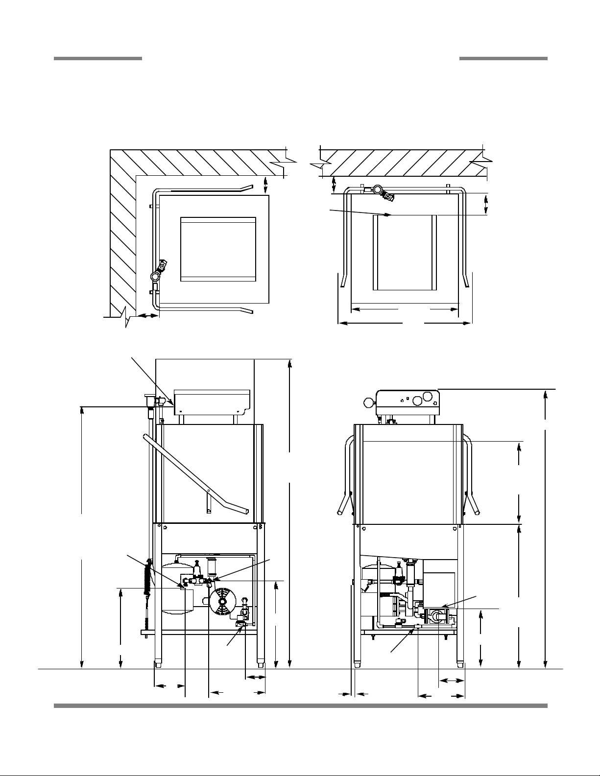
SECTION 1: SPECIFICATION INFORMATION
DIMENSIONS FOR TEMPSTAR GPX
A- DRAIN 1 1/2” NPT
B- WATER INLET 1/2” NPT
C - ELECTRICAL CONNECTION
D
C
LEGEND
D
D- STANDARD WALL CLEARANCE WITH DISHTABLE 4”
E- OUTLET TO BOOSTER HEATER 3/4” NPT
F- INLET FROM BOOSTER HEATER 3/4” NPT
D
4 7/8”
C
25 1/4”
32”
ALL DIMENSIONS ARE +/- 1/2”
DUE TO ADJUSTABLE FEET.
60 5/8”
ELECTRICAL
CONNECTION
TO THE
FLOOR
E
18 1/4”
5”
F
4 1/4”
13 1/4”
76”
W/ DOOR
OPEN
B
21”
1”
64 3/8”
17”
MACHINE
OPENING
A
14"
34”
TABLE
HEIGHT
F
14"
11”
Tempstar/HH GPX Series Technical Manual 7610-002-57-32
Issued: 07-24-2006 Revised: N/A
4
Page 10
LEGEND:
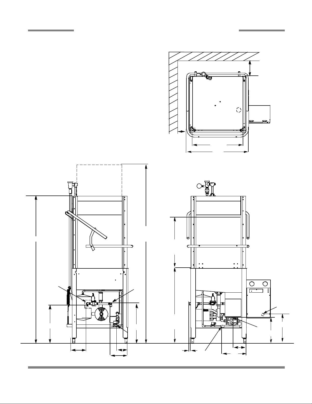
SECTION 1: SPECIFICATION INFORMATION
DIMENSIONS FOR TEMPSTAR HH GPX
A- DRAIN 1 1/2” NPT
B- WATER INLET 1/2” NPT
C - ELECTRICAL CONNECTION
D- STANDARD WALL CLEARANCE WITH DISHTABLE 4”
E- OUTLET TO BOOSTER HEATER 3/4” N.P.T.
F- INLET FROM BOOSTER HEATER 3/4” N.P.T.
ALL DIMENSIONS ARE +/- 1/2” DUE TO ADJUSTABLE FEET.
D
D
25 1/4”
32”
74 3/4”
E
16 1/4”
5”
86 1/4”
W/ DOOR
OPEN
17”
MACHINE
OPENING
B
34”
TABLE
19”
HEIGHT
F
4 1/4”
7 1/4”
Tempstar/HH GPX Series Technical Manual 7610-002-57-32
Issued: 07-24-2006 Revised: N/A
1”
C
12 3/4”
A
12 1/4”
F
11”
3”
5
Page 11
SECTION 1: SPECIFICATION INFORMATION
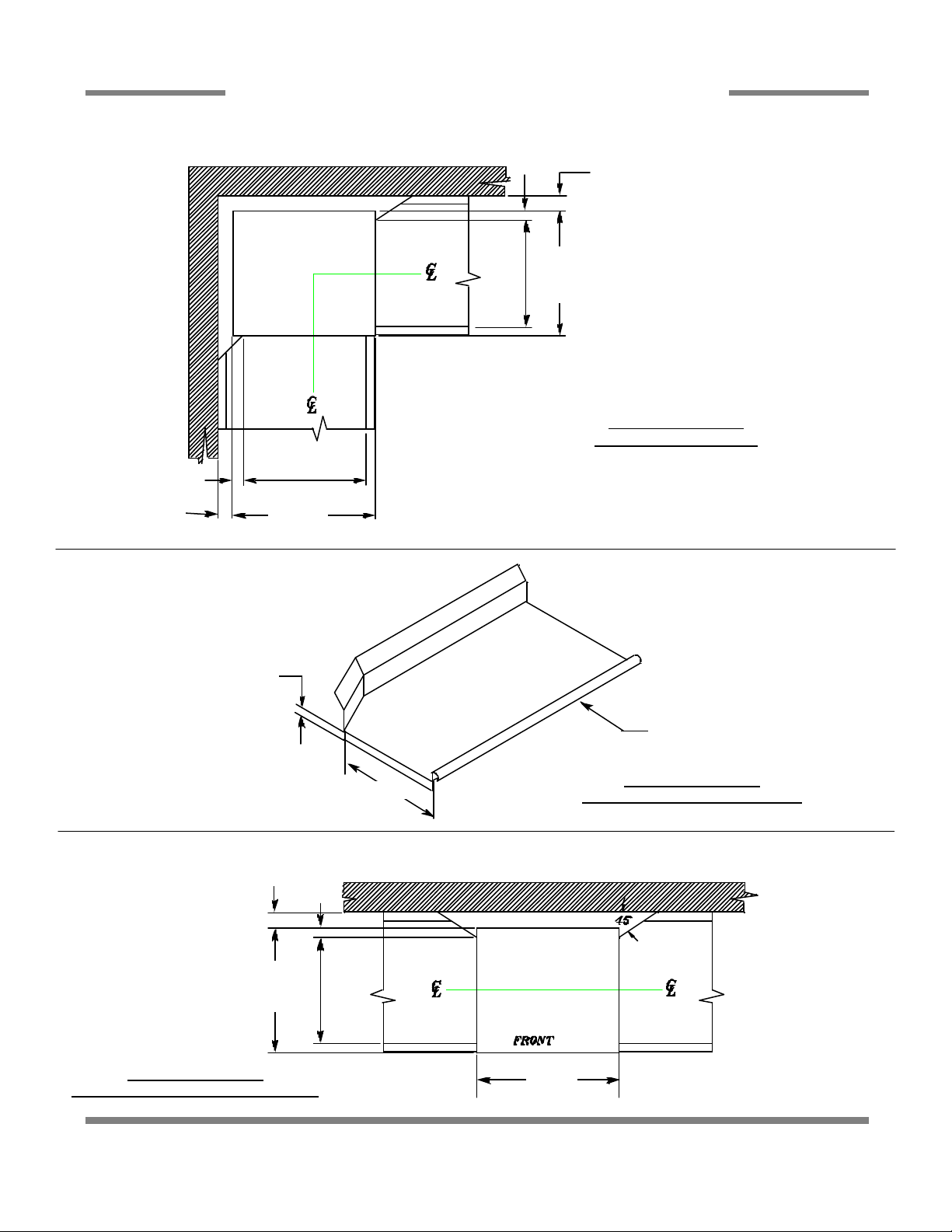
TABLE DIMENSIONS
2 1/2”
4” MINIMUM
20 1/2”
OPENING
25 1/4”
2 1/2”
20 1/2”
OPENING
4” MINIMUM
25 1/4”
TABLE DIMENSIONS
CORNER INSTALLATION
3/4”
4” MINIMUM
25 1/4”
TABLE DIMENSIONS
STRAIGHT THROUGH INSTALLATION
2 1/2”
20 1/2”
OPENING
20 1/2”
1 1/2” ROLL
TABLE DIMENSIONS
CONNECTION TO DISHMACHINE
25 1/4”
Tempstar/HH GPX Series Technical Manual 7610-002-57-32
Issued: 07-24-2006 Revised: N/A
6
Page 12

SECTION 2:
INSTALLATION/OPERATION
INSTRUCTIONS
7
Page 13

SECTION 2: INSTALLATION/OPERATION INSTRUCTIONS
INSTALLATION INSTRUCTIONS
VISUAL INSPECTION: Before installing the unit, check the container and machine for damage. A damaged container is an indi-
cator that there may be some damage to the machine. If there is damage to both the container and machine, do not throw away
the container. The dishmachine has been inspected and packed at the factory and is expected to arrive to you in new, undamaged condition. However, rough handling by carriers or others may result in there being damage to the unit while in transit. If
such a situation occurs, do not return the unit to Jackson; instead, contact the carrier and ask them to send a representative to
the site to inspect the damage to the unit and to complete an inspection report. You must contact the carrier within 48 hours of
receiving the machine. Also, contact the dealer through which you purchased the unit.
UNPACKING THE DISHMACHINE: Once the machine has been removed from the container, ensure that there are no missing parts from the machine. This may not be obvious at first. If it is discovered that an item is missing, contact Jackson immediately to have the missing item shipped to you.
LEVEL THE DISHMACHINE: The dishmachine is designed to operate while being level. This is important to prevent any damage to the machine during operation and to ensure the best results when washing ware. The unit comes with adjustable bullet
feet, which can be turned using a pair of channel locks or by hand if the unit can be raised safely. Ensure that the unit is level
from side to side and from front to back before making any connections.
PLUMBING THE DISHMACHINE: All plumbing connections must comply with all applicable local, state, and national plumbing codes. The plumber is responsible for ensuring that the incoming water line is thoroughly flushed prior to connecting it to
any component of the dishmachine. It is necessary to remove all foreign debris from the water line that may potentially get
trapped in the valves or cause an obstruction. Any valves that are fouled as a result of foreign matter left in the water line, and
any expenses resulting from this fouling, are not the responsibility of the manufacturer.
CONNECTING THE DRAIN LINE: The drain for the Tempstar models covered in this manual are gravity discharge drains. All
piping from the 1-1/2” FNPT connection on the wash tank must be pitched (1/4” per foot) to the floor or sink drain. All piping
from the machine to the drain must be a minimum 1-1/2” NPT and shall not be reduced. There must also be an air gap between
the machine drain line and the floor sink or drain. If a grease trap is required by code, it should have a flow capacity of 5 gallons per minute.
NOTE: This equipment is not recommend for use with deionized water or other aggressive fluids. Use of deionized water or other aggressive fluids will result in corrosion and failure of materials and components. Use of
deionized water or other aggressive fluids will void the manufacturer's warranty.
WATER SUPPLY CONNECTION: Ensure that you have read the section entitled “PLUMBING THE DISHMACHINE” above
before proceeding. Install the water supply line (1/2” pipe size minimum) to the dishmachine line strainer using copper pipe. It
is recommended that a water shut-off valve be installed in the water line between the main supply and the machine to allow
access for service. The water supply line is to be capable of 25 PSI “flow” pressure at the recommended temperature indicat ed on the data plate. For the Tempstar GPX, the line should also have the capacity to supply 52.2 GPH @ 25 PSI “flow” pressure.
For the Tempstar HH GPX, the line should also have the capacity to supply 72 GPH @ 25 PSI “flow” pressure.
In areas where the water pressure fluctuates or is greater than the recommended pressure, it is suggested that a water pres-
sure regulator be installed. The Tempstar models covered in this manual come with water pressure regulators as standard
equipment. Please notify Jackson immediately if this component is not present on your machine.
Do not confuse static pressure with flow pressure. Static pressure is the line pressure in a “no flow” condition (all valves and
services are closed). Flow pressure is the pressure in the fill line when the fill valve is opened during the cycle.
It is also recommended that a shock absorber (not supplied with the Tempstar models) be installed in the incoming water line.
This prevents line hammer (hydraulic shock), induced by the solenoid valve as it operates, from causing damage to the equipment.
WATER CONNECTION TO THE GAS BOOSTER HEATER: Refer to page entitled “GAS BOOSTER HEATER CONNECTIONS”.
Tempstar/HH GPX Series Technical Manual 7610-002-57-32
Issued: 07-24-2006 Revised: N/A
8
Page 14

SECTION 2: INSTALLATION/OPERATION INSTRUCTIONS
INSTALLATION INSTRUCTIONS
GAS BOOSTER HEATER ELECTRICAL INSTALLATION: The gas booster heater must have a separate electric hookup than
that supplied to the dishmachine. Please refer to the manual supplied with your gas booster heater.
GAS CONNECTION TO THE BOOSTER HEATER: Please refer to the manual supplied with your gas booster heater.
VENTILATION OF THE GAS BOOSTER HEATER: Please refer to the manual supplied with your gas booster heater.
PLUMBING CHECK: Slowly turn on the water supply to the machine after the incoming fill line and the drain line have been
installed. Check for any leaks and repair as required. All leaks must be repaired prior to placing the machine in operation.
ELECTRICAL POWER CONNECTION: Electrical and grounding connections must comply with the applicable portions of the
National Electrical Code ANSI/NFPA 70 (latest edition) and/or other electrical codes.
Disconnect electrical power supply and place a tag at the disconnect switch to indicate that you are working on the circuit.
The dishmachine data plate is located on the right side and to the front of the machine. Refer to the data plate for machine
operating requirements, machine voltage, total amperage load and serial number.
To install the incoming power lines, remove the control box cover. Install 3/4” conduit into the pre-punched holes in the back of
the control box. Route power wires and connect to power block and grounding lug. Install the service wires (L1 and L2) to the
appropriate terminals as they are marked on the terminal block. Install the grounding wire into the lug provided. and tighten the
connections. It is recommended that “DE-OX” or another similar anti-oxidation agent be used on all power connections.
VOLTAGE CHECK: Ensure that the power switch is in the OFF position and apply power to the dishmachine. Check the incoming power at the terminal block and ensure it corresponds to the voltage listed on the data plate. If not, contact a qualified service agency to examine the problem. Do not run the dishmachine if the voltage is too high or too low. Shut off the service breaker and mark it as being for the dishmachine. Advise all proper personnel of any problems and of the location of the service
breaker. Replace the control box cover and tighten down the screws.
Tempstar/HH GPX Series Technical Manual 7610-002-57-32
Issued: 07-24-2006 Revised: N/A
9
Page 15
SECTION 2: INSTALLATION/OPERATION INSTRUCTIONS
GAS BOOSTER HEATER CONNECTIONS
WARNING
ENSURE THAT THERE IS NO ELECTRICAL POWER APPLIED TO THE MACHINE WHEN MAKING GAS CONNECTION.
CHECK ALL GAS CONNECTIONS FOR LEAKS PRIOR TO APPLYING POWER.
THE GASES USED FOR COMBUSTION IN THIS DISH MACHINE ARE HIGHLY FLAMMABLE.
DO NOT SMOKE AROUND THIS MACHINE.
ENSURE THAT THE AREA WHERE THIS MACHINE IS TO BE INSTALLED IS WELL-VENTILATED TO PREVENT THE
BUILD-UP OF COMBUSTIBLE GASES.
ENSURE THAT ALL LOCAL HEALTH, FIRE, AND BUILDING CODES ARE BEING ADHERED TO WHEN INSTALLING
THIS MACHINE. VERIFY WITH LOCAL OFFICIALS IF THERE ARE ANY QUESTIONS.
INSTALL A SHUT-OFF VALVE AT THE GAS SOURCE.
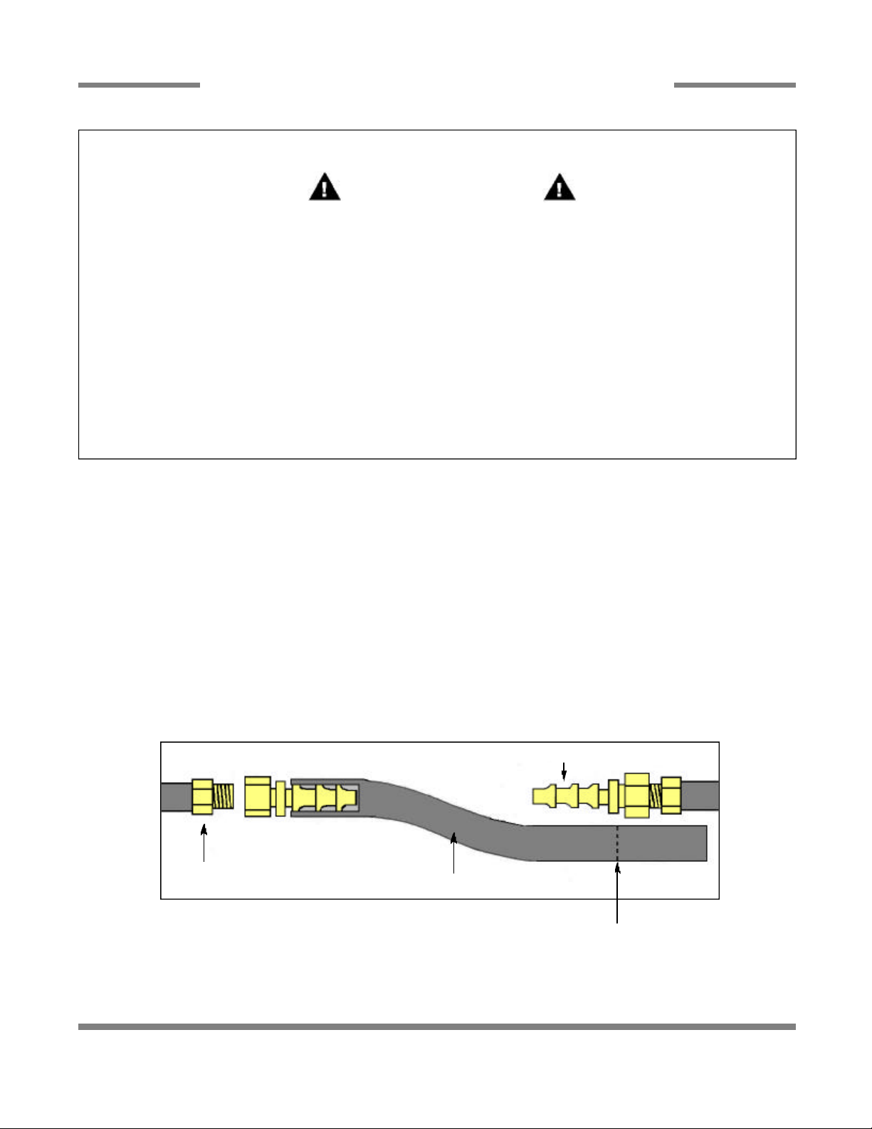
Due to the fact that each customer may have different requirements for the orientation of the gas booster heater relative to the
main dishmachine, the hose lengths that connect the two units must be customized during each installation.
To prevent incorrect measurements of the hose, it is recommended to place one barbed hose fitting into the end of the uncut
length of hose coil and attach that fitting to an appropriate connection. Run the hose to the corresponding connection on the
other unit before cutting the hose. Use a barbed hose fitting that is screwed into the second connection on the other unit before
cutting the hose. Use a barbed hose fitting that is screwed onto the second connection to gauge the correct distance. Ensure
a smooth “flow” of hose without any sharp turns or kinks.
To aid in pushing the barbed hose fitting into the hose, place the fitting on a hard surface (i.e. the floor) with the barbed end of
the fitting pointing upward and push the hose down onto the fitting. A small amount of lubricant (i.e. petroleum jelly) may aid in
this process.
Barbed Hose Fitting
Attach the hose fitting to
this connection before
Connection
making the cut at the
other end of the hose.
Hose
Cut the hose at the location where
the hose is even with the yellow
plastic stop.
Tempstar/HH GPX Series Technical Manual 7610-002-57-32
Issued: 07-24-2006 Revised: N/A
10
Page 16
SECTION 2: INSTALLATION/OPERATION INSTRUCTIONS
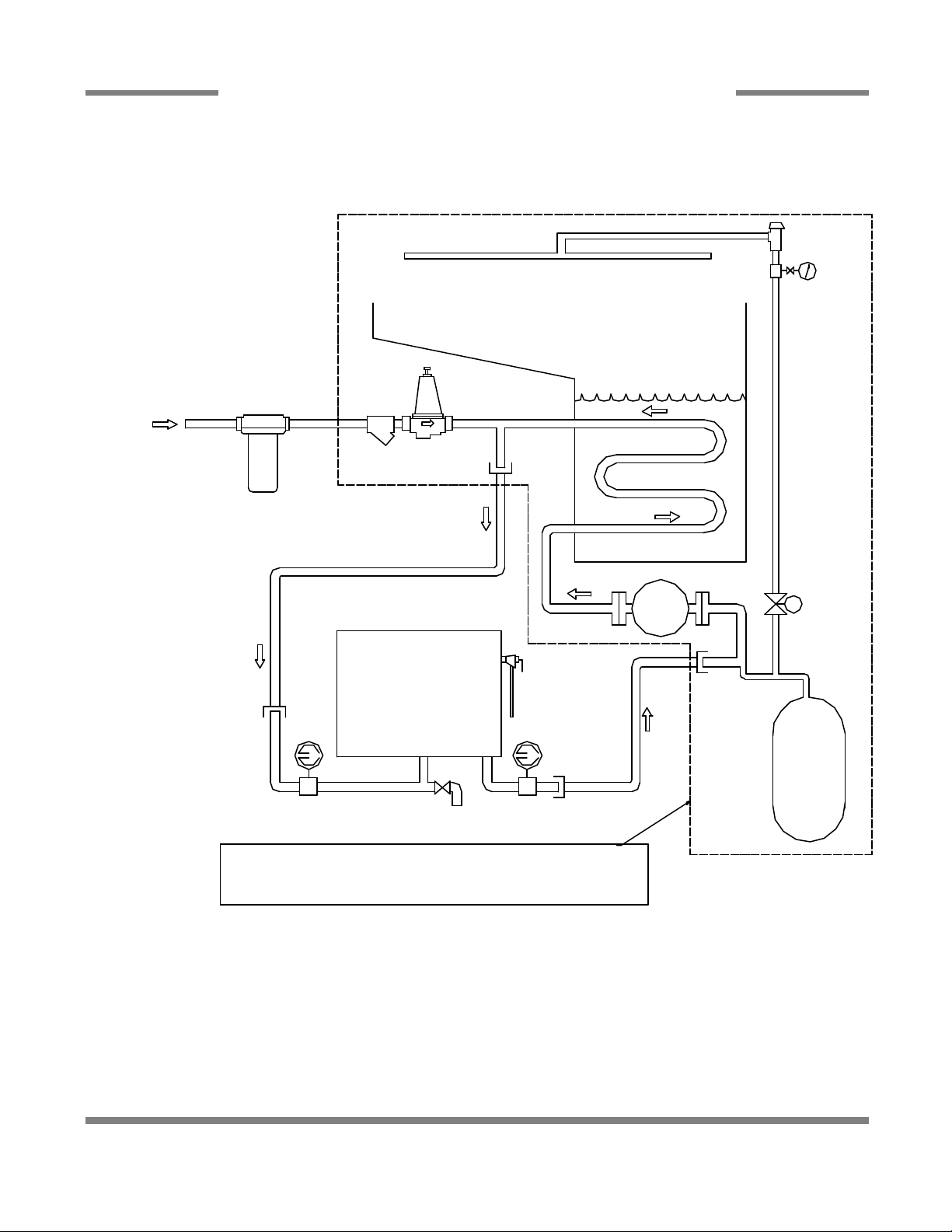
GAS BOOSTER HEATER CONNECTIONS (CONTINUED)
BUILDINGS
WATER
SUPPLY
AN ASTERISK ( )
DENOTES ITEMS
INCLUDED WITH
*
PHOSPHATE
WATER
TREATMENT
CARTRIDGE
*
THE GAS BOOSTER
HEATER
RINSE ARM
DISHMACHINE
PRESSURE
REGULATING
VALVE
Y-STRAINER
3/4" HOSE
GAS BOOSTER
*
TEMPERATURE/PRESSURE
*
GAGE
HEATER
INLET OUTLET
DRAIN VALVE
PRESSURE
*
RELIEF
VALVE
3/4" HOSE
TEMPERATURE/PRESSURE
*
GAGE
ALL COMPONENTS WITHIN THE DOTTED REGION
ARE FOUND WITHIN THE FOOTPRINT OF THE MACHINE.
ALL OTHER ITEMS ARE INSTALLED AT THE SITE.
HEATING COIL
RECIRC
PUMP
VACUUM
BREAKER
PRESSURE
GAGE
RINSE
SOLENOID
VALVE
S
THERMAL
EXPANSION
TANK
Tempstar/HH GPX Series Technical Manual 7610-002-57-32
Issued: 07-24-2006 Revised: N/A
11
Page 17

SECTION 2: INSTALLATION/OPERATION INSTRUCTIONS
OPERATION INSTRUCTIONS
PREPARATION: Before proceeding with the start-up of the unit, verify the following:
1. The pan strainer and pump suction strainer are in place and are clean.
2. The overflow tube and o-ring are installed.
3. That the wash and rinse arms are screwed securely into place and that their endcaps are tight. The wash and rinse arms
should rotate freely.
GAS BOOSTER HEATER OPERATION: For all start up and operation information, please refer to the manual supplied with
your gas booster heater.
POWER UP: To energize the unit, turn on the power at the service breaker. The voltage should have been previously verified
as being correct. If not, the voltage will have to be verified.
FILLING THE WASH TUB (TEMPSTAR GPX): Ensure that the delime switch is in the NORMAL position, and place the power
switch into the ON position. The Tempstar model should fill automatically and shut off when the appropriate level is reached
(just below the pan strainer). Verify that the drain stopper is preventing the wash tub water from leaking excessively. There may
be some slight leakage from the drain hole. Verify that there are no other leaks on the unit before proceeding any further. The
wash tub must be completely filled before operating the wash pump to prevent damage to the component. Once the wash tub
is filled, the unit is ready for operation.
FILLING THE WASH TUB (TEMPSTAR HH GPX): For the initial fill, ensure that the cycle selection switch is in the “AUTO”
(automatic) position, and place the power switch in the “ON” position. The unit will fill automatically and run through a rinse
cycle. Open the doors and verify that the water level is correct. Hereafter, the water level is controlled by the overflow tube.
Verify that the drain stopper is preventing the wash tub water from draining excessively. There may be some slight leakage from
the drain hole. Verify that there are no other leaks on the unit before proceeding any further. The wash tub must be complete ly filled before operating the wash pump to prevent damage to the component. Once the wash tub is filled, the unit is ready for
operation.
WARE PREPARATION: Proper preparation of ware will help ensure good results and less re-washes. If not done properly, ware
may not come out clean and the efficiency of the dishmachine will be reduced. It is important to remember that a dishmachine
is not a garbage disposal and that simply throwing unscraped dishes into the machine simply defeats the purpose altogether
of washing the ware. Scraps should be removed from ware prior to being loaded into a rack. Pre-rinsing and pre-soaking are
good ideas, especially for silverware and casserole dishes. Place cups and glasses upside down in racks so that they do not
hold water during the cycle. The dishmachine is meant not only to clean, but to sanitize as well, to destroy all of the bacteria
that could be harmful to human beings. In order to do this, ware must be properly prepared prior to being placed in the machine.
DAILY MACHINE PREPARATION: Refer to the section entitled “PREPARATION” at the top of this page and follow the instructions there. Afterwards, check that all of the chemical levels are correct and/or that there is plenty of detergent available for the
expected workload.
WARM-UP CYCLES: For a typical daily start-up, it may be necessary to run the machine through 3 cycles to ensure that all of
the cold water is out of the system and to verify that the unit is operating correctly. To cycle the machine, ensure that the power
is on and that the tub has filled to the correct level. Lift the doors and the cycle light will illuminate. When the light goes out,
close the doors, the unit will start, run through the cycle, and shut off automatically. Repeat this two more times. The unit should
now be ready to proceed with the washing of ware.
WASHING A RACK OF WARE: To wash a rack, open the doors completely (being careful for hot water that may drip from the
doors) and slide the rack into the unit. Close the doors and the unit will start automatically. Once the cycle is completed, open
the door (again watching for the dripping hot water) and remove the rack of clean ware. Replace with a rack of soiled ware and
close the doors. The process will then repeat itself.
Tempstar/HH GPX Series Technical Manual 7610-002-57-32
Issued: 07-24-2006 Revised: N/A
12
Page 18

SECTION 2: INSTALLATION/OPERATION INSTRUCTIONS
OPERATION INSTRUCTIONS (CONTINUED)
OPERATIONAL INSPECTION: Based upon usage, the pan strainer may become clogged with soil and debris as the workday
progresses. Operators should regularly inspect the pan strainer to ensure it has not become clogged. If the strainer does, it will
reduce the washing capability of the machine. Instruct operators to clean out the pan strainer at regular intervals or as required
by work load.
SHUTDOWN AND CLEANING: At the end of the workday, close the doors. When the unit completes the cycle, turn the power
switch to the OFF position and open the doors. Remove and clean the pan strainer. Remove the drain stopper from the tub and
allow the tub to drain (NOTE: the wash tank water will be hot so caution is advised). Once the wash tub is drained, remove the
pump suction strainer. Remove soil and debris from the strainer and set to the side. Unscrew the wash and rinse arms from
their manifolds. Remove the endcaps and flush the arms with water. Use a brush to clean out the inside of the arms. If the nozzles appear to be clogged, use a toothpick to remove the obstruction. Wipe the inside of the unit out, removing all soil and
scraps. Reassemble the wash and rinse arms and replace them in the unit. The arms only need to be hand tight, do not use
tools to tighten them down. Reinstall the drain stopper
and strainers and close the doors.
WATER CONSUMPTION ISSUES AND EFFICIENCY: The Tempstar HH GPX provides you, the customer, with the ability to
control the hourly rack capacity of the machine. Extending the wash cycle to wash severely soiled ware, such as mixing bowls,
does not increase the machine’s water consumption. However, selecting a longer time cycle does lower the amount of dishes
the machine will be able to wash per hour. It is important for operators to select the correct wash cycle depending on the amount
of washing required. Not every rack of dishes requires the machine to be set on the longest wash cycle!
Using good prescrapping procedures and observing the results of individual racks of ware, operators will soon gain the experience and knowledge required to ensure that the Tempstar HH GPX operates at peak efficiency for your needs.
Water hardness and detergent usage will also effect the results of the Tempstar HH GPX. This manual provides a page enti tled “Detergent Control” for your reference. It is recommended that owners and operators take the time to carefully review this
section in order to ensure that everything is done to make sure the Tempstar HH GPX operates at peak performance!
Tempstar/HH GPX Series Technical Manual 7610-002-57-32
Issued: 07-24-2006 Revised: N/A
13
Page 19

SECTION 3:
PREVENTATIVE MAINTENANCE
14
Page 20

SECTION 3: PREVENTATIVE MAINTENANCE
PREVENTATIVE MAINTENANCE
The dishmachines covered in this manual are designed to operate with a minimum of interaction with the operator. However,
this does not mean that some items will not wear out in time. Jackson highly recommends that any maintenance and repairs
not specifically discussed in this manual should be performed by QUALIFIED SERVICE PERSONNEL ONLY. Performing maintenance on your dishmachine may void your warranty if it is still in effect, so if you have a question or concern, do not hesitate
to contact one of the QUALIFIED SERVICE AGENCIES listed in the back of this manual.
There are many things that operators can do to prevent catastrophic damage to the dishmachine. One of the major causes of
component failure has to do with prescrapping procedures. A dishmachine is not a garbage disposal; any large pieces of material that are put into the machine shall remain in the machine until they are either broken up (after spreading out on your ware!)
or physically removed. Strainers are installed to help catch debris, but they do no good of they are clogged. Have operators
regularly inspect the pan strainers to ensure (1) that they are free of soil and debris and (2) they are laying flat in the tub.
When cleaning out strainers, do NOT beat them on waste cans. The strainers are made of metal and can be forgiving; but once
severe damage is done, it is next to impossible for the strainer to work in the way it was designed to. Wipe out strainers with
a rag and rinse under a faucet if necessary. For stubborn debris, a toothpick should be able to dislodge any obstructions from
the perforations. Always ensure that strainers are placed back in the machine before operation and that they lay flat in the tub.
You may wish to also refer to the page entitled “Detergent Control” in order to learn more about how your water hardness will
effect the performance of your machine. Hard water makes dishmachines work harder and decreases efficiency.
Again, it is important to remind operators that trying to perform corrective maintenance on the dishmachine could lead to larger problems or even cause harm to the operator. If a problem is discovered; secure the dishmachine using proper shut down
procedures as listed in this manual and contact a QUALIFIED SERVICE AGENCY as listed in the back of this manual.
Some problems, however, may having nothing to do with the machine itself and no amount of preventative maintanence is
going to help. A common problem has to do with temperatures being too low. Verify that the water temperatures coming to your
dishmachine match the requirements listed on the machine data plate. There can be a variety of reasons why your water temperature could be too low and you should discuss it with a QUALIFIED SERVICE AGENCY to determine what can be done.
By following the operating and cleaning instructions in this manual, you should get the most efficient results from your machine.
As a reminder, here are some steps to take to ensure that you are using the dishmachine the way it was designed to work:
1. Ensure that the water temperatures match those listed on the machine data plate.
2. Ensure that all strainers are in place before operating the machine.
3. Ensure that all wash and/or rinse arms are secure in the machine before operating.
4. Ensure that drains are closed/sealed before operating.
5. Remove as much soil from dishes by hand as possible before loading into racks.
6. Do not overfill racks.
7. Ensure that glasses are placed upside down in the rack.
8. Ensure that all chemicals being injected to machine have been verified as being at the correct concentrations.
9. Clean out the machine at the end of every workday as per the instructions in the manual.
10. Always contact a QUALIFIED SERVICE AGENCY whenever a serious problem arises.
11. Follow all safety procedures, whether listed in this manual or put forth by local, state or national codes/regulations.
Tempstar/HH GPX Series Technical Manual 7610-002-57-32
Issued: 07-24-2006 Revised: N/A
15
Page 21

SECTION 4:
TROUBLESHOOTING
16
Page 22

SECTION 4: TROUBLESHOOTING
COMMON PROBLEMS
WARNING: Inspection, testing and repair of electrical equipment should be performed only by qualified service per-
sonnel. Certain procedures in this section require electrical tests or measurements while power is applied to the
machine. Exercise extreme caution at all times. If test points are not easily accessible, disconnect power, attach test
equipment and reapply power to test. When replacing electrical parts, disconnect power at source circuit breaker.
Problem: Dishmachine will not fill after the door is close. Power “ON” light is illuminated.
1. Faulty rinse solenoid valve. Repair or replace valve as required.
2. Faulty door switch. Verify the wiring of the switch; if correct, replace the switch.
3. Fouled/faulty high level probe. Clean probe if fouled. If clean, and still not working, replace.
Problem: Dishmachine will not fill after the door is closed. Power “ON” light is not illuminated.
1. Service breaker tripped. Reset. If the breaker trips again, contact an electrician to verify the amp draw of the machine.
2. Machine not connected to power source. Verify that the machine has been properly connected to the power source.
3. Faulty power source. Verify the wiring of the switch; if correct, replace switch.
Problem: Dishmachine will not run after the door is closed. Power “ON” light is illuminated and the unit is filling.
1. Timer motor is faulty. Verify that the timer is rotating. If not, check to see that the motor is receiving power. If so, replace
the motor and/or timer assembly.
2. Wash motor faulty/damaged. Verify that the wash motor is getting power. If so, replace the motor.
3. Wash motor contactor faulty. Check for continuity; if contacts are open, replace the contactor.
Problem: (TEMPSTAR GPX) Dishmachine runs continuously in the wash cycle.
1. Machine is in Delime mode. Flip NORMAL/DELIME switch to NORMAL mode.
2. Timer motor is faulty. Verify that the timer is rotating. If not, check to see that the motor is receiving power. If so, replace
the motor and/or timer assembly.
3. Cam timer jammed by obstruction. Remove obstruction.
Problem: (TEMPSTAR HH GPX) Dishmachine runs continuously in the wash cycle.
1. Machine is in delime mode. Change Operation Mode from DELIME to NORMAL position.
2. Wash cycle delay timer is faulty. During the wash cycle, the cam timer will move for the first 30 seconds of the wash cycle.
The cycle delay timer will then cause the cam timer to stop, in order to increase the length of the wash cycle. The red light on
the delay timer is in control of the cam timer. If the red light is not turning on (only during cycles B, C or D), replace the cycle
timer.
3. Wash cycle delay timer settings not correctly adjusted. If the wash cycle delay timer and rotating cam timer are working
correctly, the time cycles on the delay timer may be incorrectly adjusted. Adjust the delay potentiometer corresponding to the
B, C or D cycle. Rerun the appropriate cycle and see if the adjustment has made any change in the length of the cycle. If not,
replace the cycle delay timer.
4. Cam timer is faulty. Confirm that the wash cycle delay timer is functioning correctly (see above). Confirm that the timer
motor is receiving power. If it is, replace the motor and/or timer assembly. Make sure there are no obstructions which limit the
rotation of the cam timer.
Problem: Wash or rinse heater does not work.
1. Faulty heater element. Check element for continuity; if open, replace the heater.
2. Faulty heater contactor. Replace the contactor.
3. Misadjusted/faulty thermostat(s). Verify operation and setting of thermostats, replace if necessary.
Problem: Dishmachine fill slowly and/or the rinse is weak.
1. Clogged or obstructed rinse arms. Remove and clean the rinse arms.
2. Low incoming water pressure. Adjust the water pressure regulator to ensure that there is 20 A5 PSI flow.
3. Y-strainer is clogged. Clean out the Y-strainer.
Tempstar/HH GPX Series Technical Manual 7610-002-57-32
Issued: 07-24-2006 Revised: N/A
17
Page 23

SECTION 4: TROUBLESHOOTING
COMMON PROBLEMS (CONTINUED)
Problem: Rinse water not reaching required temperature.
1. Faulty rinse heater. Check element for continuity; if open, replace heater.
2. Misadjusted/faulty thermostat(s). Verify operation and setting of thermostats, replace if necessary.
3. Rinse thermometer is defective. Replace thermometer.
Problem: Wash water is not reaching required temperature.
1. Faulty wash heater. Check element for continuity; if open, relace the heater.
2. Misadjusted/faulty thermostat(s). Verify operation and setting of thermostats, replace if necessary.
3. Wash thermometer is defective. Replace thermometer.
Problem: Doors will not close completely.
1. Improper spring tension. Adjust spring tension as required by loosening (not removing) spring bolt nuts and adjusting the
tension. Tighten nuts back when done.
2. Obstruction in door channel. Remove the obstruction.
3. Doors are not square with frame. Adjust the frame to accommodate the doors.
Problem: Doors are hard to open.
1. Improper tension on door springs. Adjust tension.
2. Door guides worn or obstructed. Replace if worn or cracked. Clean the door guides.
3. Doors not positioned correctly. Adjust the door positioning.
4. Dish table may be pinching the door runners. Adjust the table position.
Problem: Water leaks at the wash pump.
1. Wash pump seal defective. Replace the seal.
2. Petcock or pump drain (if equipped) not shut/tight. Close or tighten.
3. Loose hoses (hose clamps) on the wash pump. Tighten the hose clamps.
Problem: Will not rinse during autocycle.
1. Defective rinse solenoid. Repair or replace the rinse solenoid as required.
2. Faulty fill microswitch. Replace microswitch.
3. No water to the machine. Verify that there is water a 20 A5 PSI connected to the machine.
Problem: Dishes are not coming clean.
1. Machine temperatures are not up to the minimum requirements. Verify that incoming water, rinse water, and wash water
match the required temperatures as listed on the machine data plate.
2. No detergent/too much detergent. Adjust detergent concentration as required for the amount of water held by the
machine.
3. Solid dispenser canister is empty. Replace the canister.
Tempstar/HH GPX Series Technical Manual 7610-002-57-32
Issued: 07-24-2006 Revised: N/A
18
Page 24

SECTION 5:
SERVICE PROCEDURES
19
Page 25

SECTION 5: SERVICE PROCEDURES
RINSE SOLENOID VALVE REPAIR PARTS KIT
These dishmachines are equipped with electrical
solenoid valves to allow for automatic fill and rinse. These
valves are designed to specific tolerances and design aspects
that must be met in order to function properly.
Ecolab offers repair kits for replacing some of the
wear items associated with solenoid valves which will allow
you to save money in that replacement of these parts can take
place without removing the solenoid valve from the plumbing
assembly.
The instructions provided here are for maintenance
personnel only. Unauthorized persons should not attempt any
of the steps contained in these instructions.
Warning: many of the instructions and steps
within this document require the use of tools. Only
authorized personnel should ever perform any maintenance procedure on the dishmachine!
PREPARATION
1. Power must be secured to the unit at the service
breaker. Tag or lock out the service breaker to prevent accidental or unauthorized energizing of the machine.
2. Ensure that incoming water to the machine is
secured either by use of a shut-off valve or disconnecting the
incoming water line.
TOOLS REQUIRED
STEPS
1. Remove the top screw with the 5/16” nutdriver. Remove the
screw and the data plate and set to the side.
Removing the top screw
2. With the top screw and data plate removed, grasp the solenoid coil and gently pull up. The coil should slide up, allowing
you to remove it from the valve bonnet. If you are wanting to
replace the coil, continue on with Step 3. If you are wanting to
replace some of the internal components of the valve, proceed to step 12.
The following tools will be needed to perform this
maintenance evolution:
1. Small flathead screwdriver
2. Medium flathead screwdriver
2. Needle nose pliers
3. 5/16” nutdriver
4. Channel locks
5. 12” pipe wrench
TIME REQUIRED
It is estimated that it will take (1) person twenty min utes to perform this task, not including all of the items indicated in the section entitled “PREPARATION”.
IMPORTANT NOTES
1. Read these instructions thoroughly before
attempting this maintenance evolution. Become familiar with
the parts and what actions need to be taken. This will save
time in the long run!
2. The procedures demonstrated in this manual are
shown being performed on an AJ-44CE rack conveyor dishmachine. The actual maintenance steps, however, apply to
any Parker style solenoid valve found on a Jackson dishmachine.
Removing the coil
3. NOTE: Replacing the solenoid coil requires working with
the wiring of your machine. It is important that all wiring maintenance be performed by qualified personnel. Always verify
the wiring steps presented in this instruction with the schematic that shipped with the unit. A current schematic can also be
found in the unit’s installation manual. Before beginning any
step that involves working with wiring, ensure that the steps
located in the section entitled “Preparation” have been performed. Power must be secured to the machine at the service
breaker. Failure to do so could result in severe injury to maintenance personnel.
Tempstar/HH GPX Series Technical Manual 7610-002-57-32
Issued: 07-24-2006 Revised: N/A
20
Page 26

SECTION 5: SERVICE PROCEDURES
RINSE SOLENOID VALVE REPAIR PARTS KIT (CONTINUED)
Prying open the coil wire cover
4. When replacing the coil, ensure that when removing the coil
wire cover that care is taken not to damage the wires inside.
Using the medium flathead screwdriver, gently use it to open
the cover enough to where it could be pulled off.
Straightening the wires
5. Once the coil wire cover has been removed and set to the
side, take the internal wires and pull them out straight.
Loosening the conduit nut
7. Using a pair of channel locks, gently loosen the conduit
retaining ring for the conduit nut. Once it is loosened, use your
fingers to unscrew and remove it.
8. Pull the conduit away and discard the bad coil. Take the
new coil and attach the conduit, reinstall & tighten the conduit
nut, and pull the wires through so that you will be able to wire
the valve back up.
9. Reconnect the wires from the conduit to the wires from the
solenoid as they had been connected previously. Ensure that
the wire nuts are on tight.
10. Slide the coil wire cover back on, taking care not to damage the wires.
11. If you are done performing maintenance on the valve, continue on to step 23. Otherwise, please go on to step 12.L
Removing the wire nuts
6. Remove the wire nuts from the wires and separate them.
Tempstar/HH GPX Series Technical Manual 7610-002-57-32
Issued: 07-24-2006 Revised: N/A
Loosening the valve bonnet
12. To remove the valve bonnet, grasp it with the jaws of the
pipe wrench and turn to the left. Note: on some models you
may have to remove the valve in order to perform this and any
further steps. Be careful not to damage the plumbing assembly. Only use the pipe wrench enough to where you can spin
the valve bonnet off with your hand.
21
Page 27

SECTION 5: SERVICE PROCEDURES
RINSE SOLENOID VALVE REPAIR PARTS KIT (CONTINUED)
Removing the valve bonnet
13. Slowly remove the valve bonnet. Note: The spring for the
plunger is located directly under the bonnet and may come
free if you are not careful. Remove the plunger, spring and
valve bonnet and place to the side.
Removing the diaphragm
17. Remove the diaphragm retainer and then the diaphragm
itself. Many problems associated with a solenoid valve can be
traced to a clogged pilot port in the diaphragm.
Removing the O-ring
14. Remove the O-ring and inspect it. If it has any tears or cuts
or excessive flat spaces, it should be replaced.
15. Examine the threads for the valve bonnet. Check them for
scoring or signs of damage. Take a cloth and clean them out
to remove any foreign particles that might get lodged in the
threads and cause a leak. Severely damage threads should
not be repaired; instead it is recommended that the entire
valve should be replaced. These instructions do not provide
information on replacing the solenoid valve.
16. Note: Even though an O-ring may not appear damaged, it
is a good idea to go ahead and replace it if you have a new
one. This will help ensure that your valve remains leak-free in
the future!
Tempstar/HH GPX Series Technical Manual 7610-002-57-32
Issued: 07-24-2006 Revised: N/A
Pointing out the extension hole
18. As indicated in the photo above, the extension hole can
become clogged. If it is difficult to clean out, you can use a
heated straight pin to push through the hole. The center hole,
the pilot port, must also be clear. If the diaphragm is torn or
bent in any way, it must be replaced.
1
2
Diaphragm showing (1) pilot port and (2) extension hole
22
Page 28

SECTION 5: SERVICE PROCEDURES
RINSE SOLENOID VALVE REPAIR PARTS KIT (CONTINUED)
21. With the mesh screen removed, look down into the valve
and verify it is not clogged. Remove any foreign objects from
the valve body that would obstruct flow.
22. Reassemble the valve, reversing the steps needed to take
it apart. Replace defective replacement parts with new parts
from ordered kits. Ensure that components are sufficiently
tightened to prevent leakage.
AFTER MAINTENANCE ACTIONS
Removing the screen retainer
19. Using the small flathead screwdriver, lift out the screen
retainer. Verify that the holes in it are free of clogs and debris.
Removing the mesh strainer screen
20. Again using the small flathead screwdriver, carefully
remove the mesh screen from inside the valve body. The
screen should be taken and rinsed out to remove any debris
fouling it.
Reconnect the incoming water (if disconnected) and
turn on. Then restore power to the unit. Run the unit for at
least 10 minutes to ensure there are no leaks. If any problems
arise please contact your Jackson representative.
SPECIAL PARTS
Plunger and Spring Replacement Kit
06401-003-07-40
Diaphragm and O-Ring Replacement Kit (3/4”)
06401-003-07-42
110V Coil and Housing
06401-003-07-43
View inside the solenoid valve body
Tempstar/HH GPX Series Technical Manual 7610-002-57-32
Issued: 07-24-2006 Revised: N/A
23
Page 29

SECTION 5: SERVICE PROCEDURES
VACUUM BREAKER REPAIR PARTS KIT
These dishmachines are equipped with vacuum
breakers to serve as back-flow prevention devices. ASSE
requirements specify what type of back-flow prevention is necessary on dishmachines. Vacuum breakers, unlike air gaps,
have certain parts that have specific tolerances and design
aspects that must be met in order to function properly.
Ecolab offers repair kits for replacing some of the
wear items associated with vacuum breakers which will allow
you to save money in that replacement of these parts can take
place without removing the vacuum breaker from the plumbing assembly.
The instructions provided here are for maintenance
personnel only. Unauthorized persons should not attempt any
of the steps contained in these instructions.
Warning: many of the instructions and steps
within this document require the use of tools. Only
authorized personnel should ever perform any maintenance procedure on the dishmachine!
PREPARATION
1. Power must be secured to the unit at the service
breaker. Tag or lock out the service breaker to prevent accidental or unauthorized energizing of the machine.
2. Ensure that incoming water to the machine is
secured either by use of a shut-off valve or disconnecting the
incoming water line.
TOOLS REQUIRED
STEPS
1. Note: These instructions only apply to vacuum breakers
(1/2” NPT and 3/4” NPT) as pictured below. The repair kits
indicated in these instructions will only work on those style of
back-flow preventers. If you have a machine with a different
style of vacuum breaker, contact your Ecolab representative
about replacement components.
Vacuum breaker
2. Note: Even though the photos in these instructions show a
vacuum breaker that has been removed from the plumbing
assembly, these maintenance steps could be performed with
it installed so long as the requirements in the section entitled
“PREPARATION” have been met.
3. Remove the top cap by gripping firmly and turning to the
left. The cap should come off after a few turns.
The following tools will be needed to perform this
maintenance evolution:
1. Small flathead screwdriver
2. Needle nose pliers
TIME REQUIRED
It is estimated that it will take (1) person twenty min utes to perform this task, not including all of the items indicated in the section entitled “PREPARATION”.
IMPORTANT NOTES
1. Read these instructions thoroughly before
attempting this maintenance evolution. Become familiar with
the parts and what actions need to be taken. This will save
time in the long run!
Removing the cap
4. Set the cap to the side.
5. Using the needle nose pliers, gently lift out the plunger and
set to the side. Examine the brass seating surface inside the
vacuum breaker. The plunger is required to sit flat on this surface so it must be free of defects, imperfections and the like.
If there is debris, remove it. If it is chipped or cracked then the
vacuum breaker must be replaced. Failure to do so may result
in the vacuum breaker not working according to its design and
could result in damage to the dishmachine.
Tempstar/HH GPX Series Technical Manual 7610-002-57-32
Issued: 07-24-2006 Revised: N/A
24
Page 30

SECTION 5: SERVICE PROCEDURES
VACUUM BREAKER REPAIR PARTS KIT (CONTINUED)
Removing the plunger
6. Your repair kit comes with a new plunger. Examine the old
one and ensure that the mating surface is not damaged or cut.
Also inspect the rubber seal on the top of the plunger to
ensure it is in good condition and not torn.
7. If any of these conditions are present, replace the old
plunger with the new one from your kit. Verify that the new
plunger is also free from defects. If it is not, contact your
Ecolab representative immediately.
8. The plunger should drop into the vacuum breaker and seat.
Ensure it is not flipped upside down (the orange seal ring
should be up towards the top of the vacuum breaker).
9. Pick up the cap and examine it. With a soft towel, remove
any grit, grime or debris that may have gotten caught in the
threads of both the cap retainer or the vacuum breaker body.
There is an O-ring that should be present on the cap retainer
as well. Regardless of the condition of the plunger, this O-ring
should be replaced once the cap is removed. Using a small
flathead screwdriver, remove the old O-ring.
Examining the seal ring on the plunger
Examining the plunger seating surface
Replacing the O-ring
10. With the new O-ring in place, screw the cap back on the
vacuum breaker body. The cap needs to only be hand tight
(snug).
AFTER MAINTENANCE ACTIONS
1. Reconnect the incoming water (if disconnected)
and turn on. Then restore power to the unit. Run the unit for
at least 10 minutes to ensure there are no leaks. If any problems arise please contact your Jackson representative.
SPECIAL PARTS
To order the kit with components and instructions:
Components of 1/2” Repair Kit
06401-003-06-23
Components of 3/4” Repair Kit
06401-003-06-24
Tempstar/HH GPX Series Technical Manual 7610-002-57-32
Issued: 07-24-2006 Revised: N/A
25
Page 31

SECTION 6:
PARTS SECTION
26
Page 32

SECTION 6: PARTS SECTION
TEMPSTAR GPX CONTROL BOX ASSEMBLY
8, 9
10, 4
11, 4
5
6, 4, 3 7
20, 17
1
11, 4
2, 4
13, 12
16 22 19, 4
Tempstar/HH GPX Series Technical Manual 7610-002-57-32
21 15
Issued: 07-24-2006 Revised: N/A
27
23, 24
25, 4
14 18
Page 33

SECTION 6: PARTS SECTION
TEMPSTAR GPX CONTROL BOX ASSEMBLY (CONTINUED)
ITEM QTY DESCRIPTION Mfg. No.
1 1 Control Box Weldment 05700-002-57-08
2 1 Terminal Board, Dispenser 05940-001-97-91
3 1 Decal, Ground 09905-011-86-86
4 6 Locknut, 10-24 S/S Hex with Nylon Insert 05310-373-01-00
5 4 Plug, Heyco 05975-011-47-81
6 1 Wire Lug 05940-200-76-00
7 1 Decal, Use Copper Conductors 09905-011-47-35
8 1 Decal, L1, L2, L3 09905-101-12-66
9 2 Curtis Block 05940-500-02-19
10 1 Terminal Track 05700-000-43-60
11 2 Contactor 05945-109-03-69
12 8 Locknut, 6-32 S/S Hex with Nylon Insert 05310-373-03-00
13 2 Relay 05945-111-47-51
14 1 Rinse Thermometer 06685-111-68-48
15 1 Wash Thermometer 06685-111-68-49
16 1 Decal, Tempstar GPX 09905-002-31-84
17 1 Decal, Delime/Normal 09905-011-34-96
18 1 Switch 05930-002-43-44
19 1 Timer, 4 CKT 60Hz 05945-303-31-00
20 1 Switch, Wash 05930-301-21-18
21 1 Light, Red 05945-111-44-45
22 1 Light, Green 05945-111-44-43
23 1 Liquid Level Control Board 06680-200-08-21
24 4 Screw, 6-32 x 5/8" S/S 05305-011-39-85
25 1 Bracket, LLC Board Mounting 05700-002-13-22
26* 1 Cover, Control Box 05700-002-23-03
27* 1 Decal, Warning - Disconnect Power 09905-100-75-93
28* 1 Bolt, 10-32 x 1/2" Slotted Truss Head 05305-173-12-00
29* 4 Leg, Control Box Support 05700-002-33-05
30* 4 Screw, 1/4"-20 x 2 3/4" S/S Hex Head Cap 05305-274-13-00
31* 4 Washer, 1/4”-20 I.D. 05311-174-01-00
32* 4 Locknut, 1/4"-20 S/S Hex with Nylon Insert 05310-374-01-00
* Represents an item not shown.
Tempstar/HH GPX Series Technical Manual 7610-002-57-32
Issued: 07-24-2006 Revised: N/A
28
Page 34

30
29
28
26*, 27*
SECTION 6: PARTS SECTION
TEMPSTAR HH GPX CONTROL BOX ASSEMBLY
5, 6 10
9 11
12, 13
7, 8
5, 6
14, 15
24, 25
4
16
23, 13
21, 22, 2017, 18
19, 20
1, 2, 3
Tempstar/HH GPX Series Technical Manual 7610-002-57-32
Issued: 07-24-2006 Revised: N/A
29
Page 35

SECTION 6: PARTS SECTION
TEMPSTAR HH GPX CONTROL BOX ASSEMBLY (CONTINUED)
ITEM QTY DESCRIPTION Mfg. No.
1 1 Bracket, Electrical Box Mounting 05700-002-18-48
2 9 Locknut, 1/4"-20 S/S Hex with Nylon Insert 05310-374-01-00
3 9 Washer, 1/4"-20 I.D. S/S 05311-174-01-00
4 1 Control Box Weldment 05700-002-06-48
5 2 Relay 05945-111-47-51
6 4 Screw, 10-32 x 1/2" Phillips Pan Head with Washer 05305-002-32-37
7 1 Liquid Level Control 06680-200-08-21
8 3 Screw, 6-32 x 5/8" 05305-011-39-85
* 1 Bracket, LLC Board 05700-002-13-22
9 1 Thermometer, 48 Lead 06685-111-68-48
10 1 Decal, Control Box Gauge 09905-002-00-45
11 1 Thermometer, 96 Lead 06685-111-68-49
12 1 Timer, 4CKT 208-230V Single REV 05945-303-31-00
13 8 Screw, 6-32 x 3/8" SEMS with External Tooth Washer 05305-002-25-91
14 2 Contactor, 2 Pole 220V 20AMP 05945-109-03-69
15 3 Screw, 10-32 x 3/8" Phillips Pan Head 05305-173-26-00
16 1 Timer, Cycle Delay 05945-002-13-78
17 1 Curtis Block 05940-500-02-19
18 1 Decal, L1, L2, L3 09905-101-12-66
19 1 Decal, Copper Conductors 09905-011-47-35
20 4 Locknut, 10-24 S/S Hex with Nylon Insert 05310-373-01-00
21 1 Wire Lug 05940-200-76-00
22 1 Terminal Board, Dispenser 05940-001-97-91
22 1 Terminal Track 05700-000-43-60
23 1 Decal, Ground 09905-011-86-86
24 1 Cover, Control Box Weldment 05700-002-06-52
25 4 Bolt, 10-32 x 1/2" 05305-173-26-00
26* 1 Switch, 8 Button Tap Touch 05930-001-99-51
27* 1 Spacer, Switch Panel 05700-002-50-02
28 1 Decal, Control Box Cover 09905-002-31-84
29 1 Light, Red 05945-504-07-18
30 1 Light, Green 05945-504-08-18
* 1 Cover, Dielectric Control Panel 05700-021-50-89
* Represents an item not shown.
Tempstar/HH GPX Series Technical Manual 7610-002-57-32
Issued: 07-24-2006 Revised: N/A
30
Page 36

2, 3
SECTION 6: PARTS SECTION
TEMPSTAR GPX HOOD ASSEMBLY
1
4*
7
Switch Box Weldment
05700-002-14-34
6
Magnetic Reed Switch
05930-011-47-50
5
ITEM QTY DESCRIPTION Mfg. No.
1 1 Hood, Single Piece Weldment 05700-002-57-02
2 2 Bracket, Cantilever Support 05700-031-88-00
3 6 Wear Button .50 Dia. 05700-011-88-01
4* 1 Conduit Bracket (not shown) 05700-021-70-88
5 8 Bolt, 1/4”-20 x 1/2” S/S Hex Head 05305-274-02-00
6 8 Washer, 1/4” I.D. S/S 05311-174-01-00
7 14 Locknut, 1/4”-20 S/S Hex with Nylon Insert 05310-374-01-00
Tempstar/HH GPX Series Technical Manual 7610-002-57-32
Issued: 07-24-2006 Revised: N/A
31
Page 37

* Represents an item not shown.
SECTION 6: PARTS SECTION
TEMPSTAR HH GPX HOOD ASSEMBLY
1
2
3
4
4
5
2
3
5
11
*9
6
*10
12
7
8
6
*7
*8
ITEM QTY DESCRIPTION Mfg. No.
1 1 Hood Weldment 05700-002-01-23
2 6 Bolt, 1/4"-20 X 5/8" Long Hex 05305-274-24-00
3 26 Washer, 1/4" ID S/S 05311-174-01-00
4 26 Locknut, 1/4"-20 S/S Hex with Nylon Inserts 05310-374-01-00
5 26 Bolt, 1/4"-20 X 1/2" Long Hex 05305-274-02-00
6 2 Right/Left Front Outer Door Guide 05700-031-76-85
7 2 Right/Left Front Inner Door Guide 05700-031-76-82
8 2 Right/Left Front Hood Support Weldment 05700-002-17-68
9 1 Left Rear Outer Door Guide 05700-031-76-34
10 1 Left Rear Inner Door Guide 05700-031-76-33
11 1 Right Rear Outer Door Guide 05700-031-76-35
12 1 Right Rear Inner Door Guide 05700-031-76-32
Tempstar/HH GPX Series Technical Manual 7610-002-57-32
Issued: 07-24-2006 Revised: N/A
32
Page 38

Locknut, 1/4”-20 S/S ]
Hex with Nylon Insert
05310-374-02-00
Frame Weldment
Tempstar GPX
05700-031-48-01
SECTION 6: PARTS SECTION
FRAME ASSEMBLIES
Bolt, 1/4”-20 x 1/2”
05305-274-02-00
Front Panel
Tempstar GPX
05700-002-36-65
Bullet Foot
05340-108-01-03
Frame Weldment
Tempstar HH GPX
05700-002-03-49
Panel, Front
Tempstar HH GPX
05700-002-01-42
Bullet Foot
05340-108-02-06
Tempstar/HH GPX Series Technical Manual 7610-002-57-32
Issued: 07-24-2006 Revised: N/A
33
Page 39

SECTION 6: PARTS SECTION
TUB ASSEMBLY
15
16
15
2 3 6 7
4 8
5
11
9, 10
12
13, 10
14
31
1
30
3
28, 29
17
18, 10
19
SEE PAGE ENTITLED
“WASH MOTORS”
* Represents an item not shown.
Nut, 1/4”-20 Serrated Nut
05310-011-66-49
Pump Support Adjustable Bracket
05700-002-20-41
21, 2220 23 24 25, 26
Bracket, Motor Support Weldment
Tempstar GPX
05700-002-68-31
Bracket, Motor Support Weldment
Tempstar HH GPX
05700-002-20-42
27
Tempstar/HH GPX Series Technical Manual 7610-002-57-32
Issued: 07-24-2006 Revised: N/A
34
Page 40

SECTION 6: PARTS SECTION
TUB ASSEMBLY (CONTINUED)
ITEM QTY DESCRIPTION Mfg. No.
1 1 Tub Weldment, Tempstar GPX 05700-002-57-03
1 1 Tub Weldment, Tempstar HH GPX 05700-002-63-13
2 1 Rack Assembly 05700-002-01-00
3 2 Bulk Head Plug 04730-609-05-00
4 1 Gasket 05700-111-35-03
5 1 O-ring 05330-400-05-00
6 4 Bolt, Hex 3/8”-16 x 1 1/4" Long 05305-276-10-00
7 1 Lower Wash Manifold Weldment, Tempstar GPX 05700-031-46-00
7 1 Lower Wash Manifold Weldment, Tempstar HH GPX 05700-002-21-70
8 1 Suction Strainer Weldment, Tempstar GPX 05700-001-22-23
8 1 Suction Strainer Weldment, Tempstar HH GPX 05700-002-16-13
9 1 Suction Strainer Bracket, Tempstar GPX 05700-001-22-24
9 1 Suction Strainer Bracket, Tempstar HH GPX 05700-002-18-28
10 8 Locknut, 1/4"-20 with Nylon Insert 05310-374-02-00
11 1 Strainer Weldment 05700-021-50-07
12 1 Wash Overflow Weldment 05700-001-25-69
13 1 Overflow Support Bracket 05700-001-27-55
14 1 O-Ring 05330-400-05-00
15 2 Clamp, Hose 1 5/16” to 2 1/4” 04730-719-01-37
16 1 Discharge Hose 05700-011-88-24
17 1 Nipple 05700-021-34-84
18 1 Pump Support Bracket Assembly, Tempstar GPX 05700-002-00-46
18 1 Pump Support Bracket Assembly, Tempstar HH GPX 05700-002-22-73
19 1 Clamp, Hose 5 5/8" to 6" 04730-011-34-90
20 1 Connector, 1/2” 90° 05975-111-01-00
21 4 Nut, 3/8"-16 S/S Hex 05310-276-01-00
22 4 Lockwasher 3/8” 05311-276-01-00
23 1 Fitting, Olflex 05975-205-43-00
24 1 Union, 1/4” 05700-001-16-52
25 1 Clamp, 1/8" Nylon 05975-601-10-15
26 1 Locknut, 6-32 with Nylon Insert 05310-373-03-00
27 4 Locknut, 10-24 with Nylon Insert 05310-373-01-00
28 1 Cover, Wash 05700-031-47-57
29 1 Decal, Warning-Disconnect Power 09905-100-75-93
30 1 Kit, Thermostat Regulating, Tempstar GPX 06401-003-18-25
30 1 Kit, Thermostat Regulating, Tempstar HH GPX 06401-003-18-27
31 1 Fitting, 1/4" Imperial Brass 05310-924-02-05
The Tempstar models covered in this manual come supplied with various wash motor assemblies (a wash motor assembly
includes the wash motor and the pump end), depending on the characteristics of the machine. To ensure that you order the
correct wash motor assembly for the model you are servicing, please refer to the following table:
Model Volts Hz Phase Wash Motor Assembly
Tempstar GPX 208 60 1 06105-121-35-18
Tempstar GPX 230 60 1 06105-121-35-18
Tempstar HH GPX 208 60 1 06105-002-01-29
Tempstar HH GPX 230 60 1 06105-002-01-29
Important note: When servicing a wash
motor, it is important to refer to the wiring
schematic found on the motor, to ensure
that the motor is wired correctly. Different
manufacturers of motors may not use the
same wire color codes and therefore, your
new motor, which may have been built by
someone different than who built your original motor, may not connect using the same
wires. Always refer to the wiring diagrams
on the motor you are installing. If the motor
you are installing has had the schematic
removed, contact Jackson MSC immediately for technical support.
Tempstar/HH GPX Series Technical Manual 7610-002-57-32
Issued: 07-24-2006 Revised: N/A
35
Page 41

SECTION 6: PARTS SECTION
CANTILEVER ARM/DOOR ASSEMBLIES TEMPSTAR GPX
23, 18
24, 18
14
1310, 11, 12
2
3
1
4
5
6
9
15, 16
7
8
17, 18
22
Cotter Pin 3/32" x 3/4"
05315-207-01-00
Yoke
05700-000-75-78
Bushing
03120-100-03-00
2021, 25
19, 11, 12
Washer, Nylon
05311-369-03-00
Clevis Pin
05315-700-01-00
Nut, 3/8"-16 S/S Hex Locking
05310-256-04-00
Tempstar/HH GPX Series Technical Manual 7610-002-57-32
Issued: 07-24-2006 Revised: N/A
36
Page 42

SECTION 6: PARTS SECTION
CANTILEVER ARM/DOOR ASSEMBLIES TEMPSTAR GPX (CONTINUED)
ITEM QTY DESCRIPTION Mfg. No.
1 1 Cantilever Arm 05700-031-50-67
2 2 Spring Pin, 1/4" x 1 1/8" 05315-407-06-00
3 2 Yoke Assembly 05700-000-75-77
4 2 Rod, Spring 05700-002-29-38
5 2 Spring 05340-109-02-00
6 2 Bolt, Cantilever Hanger Eye 3/8"-16 05306-956-05-00
7 2 Washer, 3/8" ID x 7/8" OD S/S 05311-176-02-00
8 4 Nut, 3/8"-16 S/S Hex 05310-276-01-00
9 2 Connector, Cantilever Arm 05700-011-90-99
10 2 Screw 1/4"-20 x 1 1/2" Long S/S 05305-274-23-00
11 4 Washer, 1/4" S/S 05311-174-01-00
12 4 Locknut, 1/4"-20 S/S Hex with Nylon Insert Low Profile 05310-374-02-00
13 2 Sleeve, Cantilever Arm 05700-000-85-69
14 2 Plug, Cantilever Arm 05340-011-35-00
15 1 Magnet, Reed Switch 05930-111-51-68
16 2 Locknut, 8-32 S/S Hex with Nylon Insert 05310-272-02-00
17 1 Door, Right Side (Complete Assembly) 05700-002-30-88
17A 1 Right Door Weldment with Studs 05700-002-29-85
18 6 Door, Guides 05700-111-33-59
19 2 Screw, 1/4"-20 x 1/2" Long S/S 05305-274-02-00
20 2 Spacer, PB Bolt 05700-000-29-40
21 4 Door Plate 05700-002-20-78
22 2 Door Connector Bracket 05700-021-33-39
23 1 Door, Front (Complete Assembly) 05700-002-30-89
23A 1 Door Only, Front 05700-002-29-83
24 1 Door, Left Side (Complete Assembly) 05700-002-30-87
24A 1 Door Only, Left Side 05700-002-29-86
25 8 Locknut, 1/4"-20 with Nylon Insert 05310-374-02-00
Tempstar/HH GPX Series Technical Manual 7610-002-57-32
Issued: 07-24-2006 Revised: N/A
37
Page 43

SECTION 6: PARTS SECTION
CANTILEVER ARM/DOOR ASSEMBLIES TEMPSTAR HH GPX
1
2
3, 4, 5
10
9
29, 30 31, 32
35, 24
33, 34
17, 18
36, 22
6
17, 18
19, 20
25, 4, 5
8
7
21, 22
23, 4, 24
11
12
13
12
14
15
16
28
26
27, 22
Tempstar/HH GPX Series Technical Manual 7610-002-57-32
Issued: 07-24-2006 Revised: N/A
38
Page 44

SECTION 6: PARTS SECTION
CANTILEVER ARM/DOOR ASSEMBLIES TEMPSTAR HH GPX (CONTINUED)
ITEM QTY DESCRIPTION Mfg. No.
1 1 Cantilever Arm 05700-031-92-44
2 2 Sleeve, Cantilever Arm 05700-000-85-69
3 2 Screw, 1/4"-20 x 1 1/2" Long Hex Head 05305-274-23-00
4 4 Washer, 1/4" ID S/S 05311-174-01-00
5 4 Locknut, 1/4"-20 S/S Low Profile with Nylon Insert 05310-374-02-00
6 4 Plug, Cantilever 05340-011-35-00
7 2 Connecting Link 05700-021-92-45
8 2 Spring Pin, 1/4" Dia. x 1 1/8" Long 05315-407-06-00
9 2 Yoke Assembly 05700-000-75-77
10 2 Nut, 3/8"-16 S/S Hex Locking 05310-256-04-00
11 2 Rod, Spring Connecting 05700-002-00-91
12 4 Plate, Spring Multiplier 05700-002-00-88
13 4 Spring, Cantilever Door 05340-111-35-22
14 4 Bolt, Cantilever Hanger Eye 3/8"-16 05306-956-05-00
15 4 Washer, Impeller 05311-176-02-00
16 8 Nut, 3/8"-16 S/S Hex 05310-276-01-00
* 2 Door, Upper, Left and Right Assemblies 05700-002-01-30
17 2 Door, Upper, Left and Right Weldment 05700-002-29-59
18 4 Glide, Upper Door 05700-002-00-83
* 1 Door, Lower, Right Assembly 05700-002-01-33
19 1 Door, Lower, Right 05700-031-76-80
20 2 Glide, Lower Door 05700-002-23-64
21 1 Door Stop Magnet Assembly 05700-002-25-08
* 1 Door Stop Magnet Weldment 05700-002-01-27
* 1 Magnet 05930-111-69-25
* 2 End Cap 05700-011-60-92
22 6 Wear Button 05700-011-88-01
23 20 Screw, 1/4"-20 x 5/8" 05305-274-24-00
24 20 Locknut, 1/4"-20 S/S Hex with Nylon Insert 05310-374-01-00
25 2 Screw, 1/4"-20 x 1/2" Long Hex Head 05305-274-02-00
26 2 Spacer, PB Bolt 05700-000-29-40
27 2 Bracket, Door Connector 05700-001-99-39
28 1 Handle, Front Door Weldment 05700-002-00-90
* 1 Door, Lower, Front Assembly 05700-002-01-31
29 1 Door, Lower, Front 05700-031-76-77
30 2 Glide, Lower Door 05700-002-23-64
* 1 Door, Upper Front Assembly 05700-002-24-92
31 1 Door, Upper, Front Weldment 05700-002-29-57
32 2 Glide, Upper Door 05700-002-00-83
* 1 Door, Lower, Left Assembly 05700-002-01-32
33 1 Door, Lower, Left 05700-031-76-79
34 2 Glide, Lower Door 05700-002-23-64
35 6 Door Stop Weldment 05700-002-29-60
36 1 Door Stop 05700-002-00-84
Tempstar/HH GPX Series Technical Manual 7610-002-57-32
Issued: 07-24-2006 Revised: N/A
39
Page 45

TEMPSTAR GPX
SECTION 6: PARTS SECTION
INLET PLUMBING ASSEMBLIES
CONNECTS TO THE WASH
TANK HEATING COIL OUTLET
1
1
2
1
NOTE: ENSURE DIRECTION
OF FLOW THROUGH THE
PRESSURE REGULATING
VALVE IS IN THE CURRECT
DIRECTION.
3
7
5
4
6
ITEM QTY DESCRIPTION Mfg. No.
* 1 Plumbing, Inlet, Tempstar GPX 05700-002-56-69
1 3 Bushing, Hex 3/4” M to 1/2” F, Brass 04730-002-56-27
2 1 Outlet, Heating Coil Assembly 05700-002-56-70
3 1 Valve, Pressure Reducing, 3/4” 04820-002-51-53
4 1 Elbow, 90° 1/2” Street Brass 04730-206-08-00
5 1 Nipple, 1/2” Close Brass 04730-207-15-00
6 1 Y-Strainer, 1/2” 04730-217-01-10
7 1 Tubing, Inlet Plumbing Assembly 05700-002-56-71
2 1
TEMPSTAR HH GPX
1
ITEM QTY DESCRIPTION Mfg. No.
* 1 Plumbing, Inlet, Tempstar HH GPX 05700-002-63-16
1 3 Bushing, Hex 3/4” M to 1/2” F, Brass 04730-002-56-27
2 1 Outlet, Heating Coil Assembly 05700-002-56-70
3 1 Valve, Pressure Reducing, 3/4” 04820-002-51-53
4 2 Tubing, Inlet Plumbing Assembly 05700-002-56-71
5 1 Elbow, 90° 1/2” 04730-406-32-01
6 1 Y-Strainer, 1/2” 04730-217-01-10
3 1 4 5 4 6
Tempstar/HH GPX Series Technical Manual 7610-002-57-32
Issued: 07-24-2006 Revised: N/A
40
Page 46

SECTION 6: PARTS SECTION
RINSE HEADER PLUMBING ASSEMBLY
Rinse Header Plumbing Assembly, Tempstar GPX 05700-002-56-67
Rinse Header Plumbing Assembly, Tempstar HH GPX 05700-002-58-02
Vacuum Breaker, 1/2"
04820-003-06-13
Rinse Tube Assembly, Tempstar GPX
Rinse Tube Assembly, Tempstar HH GPX
05700-002-56-68
05700-002-58-03
Ball Valve, 1/4"
04810-011-72-67
Pressure Gauge, 0-100 PSI
06685-111-88-34
ITEM QTY DESCRIPTION Mfg. No.
* 1 Rinse Hose Assembly 05700-002-57-05
1 Hose, 1/2” x 27” 05700-002-57-04
1 Fitting, 1/2” 04730-011-93-99
Tempstar/HH GPX Series Technical Manual 7610-002-57-32
Issued: 07-24-2006 Revised: N/A
41
Page 47

SECTION 6: PARTS SECTION
RECIRCULATING PLUMBING ASSEMBLY
1
4
5
2
* The hardware is included
with pump flange (item 7).
11
3
4
*
6
10
9
8
7
7
*
The gaskets are included
with the pump (item 6).
ITEM QTY DESCRIPTION Mfg. No.
* 1 Plumbing, 110V Recirculating System Assembly 05700-002-56-64
* 1 Plumbing, 208-230V Recirculating System Assembly 05700-002-56-65
1 1 Tubing Assembly 05700-002-56-66
2 1 Tank, Thermal Expansion 05700-002-65-77
3 1 Valve, Solenoid 1/2” 110 Volt 04810-100-12-18
3 1 Valve, Solenoid 1/2” 208-230 Volt 04810-100-09-18
4 2 Nipple, 1/2” Close Brass 04730-207-15-00
5 1 Coupling, 1/2” x 3/4” Brass 04730-204-07-00
6 1 Pump, 110V Recirculating 06105-002-56-25
6 1 Pump, 208-230V Recirculating 06105-002-56-26
7 1 Pump, Flange 04320-002-38-17
8 1 Bushing, Hex 3/4” M to 1/2” F Brass 04730-002-56-27
9 1 Elbow, 90° 1/2” Street Brass 04730-206-08-00
10 1 Nipple, 1/2” x 2” Brass 04730-207-19-00
11 1 Elbow, 1/2” NPT, 90° Brass 04730-011-42-96
Tempstar/HH GPX Series Technical Manual 7610-002-57-32
Issued: 07-24-2006 Revised: N/A
42
Page 48

SECTION 6: PARTS SECTION
RINSE SOLENOID VALVE & VACUUM BREAKER REPAIR PARTS KITS
Screw
Data Plate
Valve Bonnet
Spring position is moved
for clarity.
Goes below the plunger.
Diaphragm
Retainer
Screen
Retainer
Coil & Housing
Spring
06401-003-07-40
Plunger
06401-003-07-40
O-Ring
06401-003-07-41
Diaphragm
06401-003-07-41
Data Plate
Cap Retainer
Components of
Repair Kit
06401-003-06-23
Cap Screw
Cap
O-Ring
Plunger
Body
Valve Body
Complete 110 Volt Solenoid Valve Assembly
04810-100-12-18
Coil & Housing only
06401-003-07-43
Complete 220 Volt Solenoid Valve Assembly
04810-100-09-18
Coil & Housing only
06401-003-07-44
Mesh Screen
Complete Vacuum Breaker Assembly
04820-003-06-13
Tempstar/HH GPX Series Technical Manual 7610-002-57-32
Issued: 07-24-2006 Revised: N/A
43
Page 49

18
SECTION 6: PARTS SECTION
WASH & RINSE ARM/MANIFOLD ASSEMBLIES (TEMPSTAR GPX)
19
11
18
18
1
12
18
DETAIL “A”
FINAL RINSE ARMS & MANIFOLD
2, 3, 4 5
13
16
15
14
Rinse Injector Weldment
1 per machine
05700-002-56-75
Plug, 1/8” NPT, Brass
3 per Rinse Injector
04730-209-07-37
Rinse Injector Gasket
2 per machine
05330-111-42-81
5
1
10
9, 10
6, 18
9, 10
16, 8
2, 3, 20
7
9
17
5
Tempstar/HH GPX Series Technical Manual 7610-002-57-32
Issued: 07-24-2006 Revised: N/A
16
44
9
7
5
DETAIL “B”
WASH ARMS & MANIFOLD
Page 50

SECTION 6: PARTS SECTION
WASH & RINSE ARM/MANIFOLD ASSEMBLIES (TEMPSTAR GPX) (CONTINUED)
ITEM QTY DESCRIPTION Mfg. No.
1 1 Upper Manifold 05700-031-34-82
2 4 Nut, 3/8"-16 S/S Hex 05310-276-01-00
3 4 Lockwasher, 3/8 05311-276-01-00
4 2 Bolt, Hex 3/8”-16 x 7/8" Long 05306-011-36-95
5 2 O Ring 05330-111-35-15
6 1 Positioning Bracket, Manifold Tube 05700-011-34-63
7 1 Tube, Wash Manifold 05700-031-92-58
8 2 Gasket, Manifold 05700-111-35-03
* 1 Wash Arm Assembly 05700-021-35-39
9 1 Wash Arm Weldment 05700-021-35-93
9a 1 Hub Nut 05700-011-35-94
9b 1 Hub Bushing 05700-011-35-96
9c 1 Hub Spindle 05700-011-35-95
9d 1 Ring, Retainer 05340-011-37-81
9e 15 3/16" Stainless Steel Ball 03120-100-02-00
9f 20 1/8" Stainless Steel Ball 03120-011-37-82
10 1 Bearing Assembly 05700-021-35-97
* 1 O-ring 05330-002-60-69
* 2 Rinse Arm Assembly 05700-002-58-09
11 2 Clip, Retaining, Rinse Head Bushing 05340-112-01-11
12 4 Washer 05330-011-42-10
13 2 Bushing, Rinse Head 05700-021-33-84
14 2 Rinse Arm 05700-031-49-58
15 4 Plug 04730-609-04-00
16 2 Bearing 03120-002-72-24
17 1 Lower Wash Manifold Weldment 05700-002-21-70
18 5 Locknut, 1/4"-20 S/S Hex with Nylon Insert 05310-374-01-00
19 1 Rinse Manifold Weldment 05700-002-01-19
20 2 Bolt, Hex 3/8”-16 x 1 1/4" Long 05305-276-10-00
21 1 Wash Arm, Double Assembly 05700-031-92-49
17c
17a
17b
17d
1 or 16
9
EXPLODED VIEW OF
ITEM 17
17f
17e
Tempstar/HH GPX Series Technical Manual 7610-002-57-32
Issued: 07-24-2006 Revised: N/A
45
Page 51

SECTION 6: PARTS SECTION
WASH & RINSE ARM/MANIFOLD ASSEMBLIES (TEMPSTAR HH GPX)
18
18
18
18
19
15
11
12
DETAIL “A”
FINAL RINSE ARMS & MANIFOLD
2, 3, 4
13
16
14
15
Rinse Injector Weldment
1 per machine
05700-002-56-75
Plug, 1/8” NPT, Brass
3 per Rinse Injector
04730-209-07-37
5
9, 10
6, 18
21
17, 8
1
1
10
7
9
21
17
2, 3, 20
5
WASH ARMS & MANIFOLD
5
7
5
DETAIL “B”
Tempstar/HH GPX Series Technical Manual 7610-002-57-32
Issued: 07-24-2006 Revised: N/A
46
Page 52

SECTION 6: PARTS SECTION
WASH & RINSE ARM/MANIFOLD ASSEMBLIES (TEMPSTAR HH GPX) (CONTINUED)
ITEM QTY DESCRIPTION Mfg. No.
1 1 Upper Manifold 05700-031-34-82
2 4 Nut, 3/8"-16 S/S Hex 05310-276-01-00
3 4 Lockwasher, 3/8 05311-276-01-00
4 2 Bolt, Hex 3/8”-16 x 7/8" Long 05306-011-36-95
5 2 O Ring 05330-111-35-15
6 1 Positioning Bracket, Manifold Tube 05700-011-34-63
7 1 Tube, Wash Manifold 05700-031-92-58
8 2 Gasket, Manifold 05700-111-35-03
* 1 Wash Arm Assembly 05700-021-35-39
9 1 Wash Arm Weldment 05700-021-35-93
10 1 Bearing Assembly 05700-021-35-97
* 1 O-ring 05330-002-60-69
* 2 Rinse Arm Assembly 05700-002-58-09
11 2 Clip, Retaining, Rinse Head Bushing 05340-112-01-11
12 4 Washer 05330-011-42-10
13 2 Bushing, Rinse Head 05700-021-33-84
14 2 Rinse Arm 05700-031-49-58
15 4 Plug 04730-609-04-00
16 2 Bearing 03120-002-72-24
17 1 Lower Wash Manifold Weldment 05700-002-21-70
18 5 Locknut, 1/4"-20 S/S Hex with Nylon Insert 05310-374-01-00
19 1 Rinse Manifold Weldment 05700-002-01-19
20 2 Bolt, Hex 3/8”-16 x 1 1/4" Long 05305-276-10-00
21 1 Wash Arm, Double Assembly 05700-031-92-49
Rinse Injector Gasket
2 per machine
05330-111-42-81
Tempstar/HH GPX Series Technical Manual 7610-002-57-32
Issued: 07-24-2006 Revised: N/A
47
Page 53

SECTION 6: PARTS SECTION
COIL ASSEMBLY
Complete Coil Assembly
05700-002-08-62
Stand B, Coil Support
Stand C, Coil Support
05700-002-08-52
Coil Weldment
05700-021-41-38
Stand D, Coil Support
05700-002-08-53
05700-002-08-51
Stand A, Coil Support
Adapter, Coil Nut
2 per assembly
05700-011-17-85
05700-002-08-50
Gasket, Coil
4 per assembly
05700-001-17-86
Washer, Coil
2 per assembly
05700-001-17-87
Tempstar/HH GPX Series Technical Manual 7610-002-57-32
Issued: 07-24-2006 Revised: N/A
48
Page 54

EXHAUST FAN CONTROL OPTION/SAFETY DOOR INTERLOCK (SDI) OPTION
Exhaust Fan Control
Delay Timer
05945-011-65-44
SECTION 6: PARTS SECTION
Exhaust Fan Control
2” Din Rail
05700-002-36-09
Exhaust Fan Control
Terminal Board
05940-011-84-41
Safety Door Interlock Box Bottom
05700-001-21-26
Safety Door Interlock Box Cover
05700-001-21-27
Other Safety Door Interlock (SDI) components (not shown):
Pipe Clamp (found on the side of the machine) 05700-000-35-05
Solenoid, Electrical Interlock Option 04810-100-61-33
Relay 05945-111-47-51
Tempstar/HH GPX Series Technical Manual 7610-002-57-32
Issued: 07-24-2006 Revised: N/A
49
Page 55

Left & Front False Panel
Weldment
05700-002-75-52
Right False Panel Weldment
(Use with Overflow Tube Lifter)
05700-002-98-85
Left & Front False Panel Kit
05700-002-75-59
Right False Panel Kit
(Use with Overflow Tube Lifter)
05700-002-98-86
SECTION 6: PARTS SECTION
TEMPSTAR GPX FALSE PANEL INSTALLATION
Rack rail removed & repositioned for a corner operation.
Insert this
side first.
False panel positioned in unit.
1. Loosen the rack assembly from the unit.
2. False panel will mount to the rack; inside the dishmachine.
3. Position panel in unit on side to be closed.
4. Hold panel against side of dishmachine and push up.
5. Panel will clip inside the unit under the edge of the hood.
6. Holes in false panel willl ine up with rack assembly holes.
7. Re-install screws for rack assembly which will secure false panel
to unit.
8. Re-assemble the rack track in an “L” shape for a corner operation.
Bottom of side panel.
Tempstar/HH GPX Series Technical Manual 7610-002-57-32
Issued: 07-24-2006 Revised: N/A
50
Page 56

SECTION 6: PARTS SECTION
TEMPSTAR HH GPX FALSE PANEL INSTALLATION
False Panel
05700-002-52-54
Kit, False Panel with
Mounting Hardware
05700-002-52-89
Rack rail removed and repositioned for a corner operation.
Insert this
side first.
False Panel Positioned in unit.
1. Remove the rack assembly from the dishmachine.
2. The false panel will mount inside of the dishmachine.
3. Position the panel in the dishmachine on the side to be
closed.
4. Hold the panel against the side of the dishmachine and
push upward.
5. The panel will clip in at the top, inside of the unit.
6. The holes in the false panel will line up with the rack
assembly holes.
7. Re-install the screws for the rack assembly which will
secure the false panel to the unit.
8. Re-assemble the rack track in an “L” shape for a corner
operation.
Bottom of False Panel
Tempstar/HH GPX Series Technical Manual 7610-002-57-32
Issued: 07-24-2006 Revised: N/A
51
Page 57

Elbow, 1-1/2” 90 B Street
04730-206-32-00
Nipple, 1-1/2” NPT
04730-207-40-00
Modified Compression
Fitting
05700-001-16-52
SECTION 6: PARTS SECTION
DRAIN QUENCH ASSEMBLY
Drain Quench
Assembly
06401-002-59-52
Lid, Drain Quench
05700-002-67-16
Thermostat
05930-003-13-65
Solenoid Valve
Reducer, 1-1/2” x 1/4”
04810-100-09-18
04730-002-55-76
To Dishmachine Drain
To Cold Water Supply
Tee, 1-1/2” x 1-1/2” x 1-1/2”
04730-011-69-93
Reducer, 1-1/2” to 1/2”
04730-002-55-75
Valve, Check, 1/2”
(Not Shown)
04820-002-55-77
Nipple, Close, 1/2” NPT
(Not Shown)
Box, Drain Quench
05700-002-69-96
04730-207-15-00
From the existing drain, attach the two additional Tees using the 1-1/2” NPT Close Nipples. Tighten the Reducers into the Tees
as shown above. Attach the Modified Compression Fitting into the 1-1/2” to 1/4” Reducer. Position the bulb of the thermostat
so that it rests approximately 1/4” from the bottom of the Tee. Tighten the Modified Compression Fitting as required. Attach to
the incoming cold water line. Use pipe dope or thread tape as required to prevent any leaks.
Tempstar/HH GPX Series Technical Manual 7610-002-57-32
Issued: 07-24-2006 Revised: N/A
52
Page 58

SECTION 7:
ELECTRICAL SCHEMATICS
53
Page 59

SECTION 7: ELECTRICAL SCHEMATICS
TEMPSTAR GPX 115 VOLT - 50/60 HERTZ - SINGLE PHASE
Tempstar/HH GPX Series Technical Manual 7610-002-57-32
Issued: 07-24-2006 Revised: N/A
54
Page 60

SECTION 7: ELECTRICAL SCHEMATICS
TEMPSTAR GPX 208-230 VOLT - 50/60 HERTZ - SINGLE PHASE
Tempstar/HH GPX Series Technical Manual 7610-002-57-32
Issued: 07-24-2006 Revised: N/A
55
Page 61

SECTION 7: ELECTRICAL SCHEMATICS
TEMPSTAR HH GPX 115 VOLT - 50/60 HERTZ - SINGLE PHASE
Tempstar/HH GPX Series Technical Manual 7610-002-57-32
Issued: 07-24-2006 Revised: N/A
56
Page 62

SECTION 7: ELECTRICAL SCHEMATICS
TEMPSTAR HH GPX 208-230 VOLT - 50/60 HERTZ - SINGLE PHASE
Tempstar/HH GPX Series Technical Manual 7610-002-57-32
Issued: 07-24-2006 Revised: N/A
57
Page 63

SECTION 7: ELECTRICAL SCHEMATICS
EXHAUST FAN CONTROL OPTION/SAFETY DOOR INTERLOCK (SDI) OPTION
Tempstar/HH GPX Series Technical Manual 7610-002-57-32
Issued: 07-24-2006 Revised: N/A
58
 Loading...