

Jackson Delta 5 Operators Manual

INSTALLATION, OPERATION
& SERVICE MANUAL
FOR JACKSON MODELS:
Delta 5
Delta 5 D
Jackson WWS, INC.
P.O. BOX 1060
BARBOURVILLE, KY. 40906
PHONE (606) 523-9795
FAX (606) 523-9196
www.jacksonwws.com
CHEMICAL SANITIZING DISHMACHINE
March 18, 2014
P/N 7610-003-37-08 (Revision F)

ALL NEW JACKSON DISHWASHERS ARE WARRANTED TO THE ORIGINAL PURCHASER TO BE FREE FROM DEFECTS IN MATERIAL
OR WORKMANSHIP, UNDER NORMAL USE AND OPERATION FOR A PERIOD OF (1) ONE YEAR FROM DATE OF PURCHASE, BUT IN
NO EVENT TO EXCEED (18) EIGHTEEN MONTHS FROM DATE OF SHIPMENT FROM THE FACTORY.
Jackson WWS agrees under this warranty to repair or replace, at its discretion, any original part which fails under normal use due to faulty
material or workmanship during the warranty period, providing the equipment has been unaltered, and has been properly installed, maintained
and operated in accordance with applicable factory instruction manual furnished with the machine and failure is reported to the authorized
service agency within the warranty period. This includes the use of factory specified genuine replacement parts, purchased directly from a
Jackson authorized parts distributor or service agency. Use of generic replacement parts may create a hazard and void warranty certification.
The labor to repair or replace such failed part will be paid by Jackson WWS, within the continental United States, Hawaii and Canada, during
the warranty period provided a Jackson WWS authorized service agency, or those having prior authorization from the factory, performs the
service. Any repair work by persons other than Jackson WWS authorized service agency is the sole responsibility of the customer. Labor
coverage is limited to regular hourly rates; overtime premiums and emergency service charges will not be paid by Jackson WWS.
Accessory components not installed by the factory carry a (1) one year parts warranty only. Accessory components such as table limit
switches, pressure regulators, pre-rinse units, etc. that are shipped with the unit and installed at the site are included. Labor to repair or
replace these components is not covered by Jackson WWS.
This warranty is void if failure is a direct result from shipping, handling, fire, water, accident, misuse, acts of God, attempted repair by authorized
persons, improper installation, if serial number has been removed or altered, or if unit is used for purpose other than originally intended.
TRAVEL LIMITATIONS
Jackson WWS limits warranty travel time to (2) two hours and mileage to (100) one hundred miles. Jackson WWS will not pay for travel time
and mileage that exceeds this, or any fees such as those for air or boat travel without prior authorization.
WARRANTY REGISTRATION
To register your product go to www.jacksonwws.com or call 1-888-800-5672. Failure to register your product will void the warranty.
REPLACEMENT PARTS WARRANTY
Jackson replacement parts are warranted for a period of 90 days from date of installation or 180 days from the date of shipment from the
factory, whichever occurs first.
PRODUCT CHANGES AND UPDATES
Jackson WWS reserves the right to make changes in design and specification of any equipment as engineering or necessity requires.
THIS IS THE ENTIRE AND ONLY WARRANTY OF JACKSON WWS. JACKSON’S LIABILITY ON ANY CLAIM OF ANY KIND, INCLUDING
NEGLIGENCE, WITH RESPECT TO THE GOODS OR SERVICES COVERED HEREUNDER, SHALL IN NO CASE EXCEED THE PRICE
OF THE GOODS OR SERVICES OR PART THEREOF WHICH GIVES RISE TO THE CLAIM.
THERE ARE NO WARRANTIES, EXPRESSED OR IMPLIED, INCLUDING FOR FITNESS OR MERCHANTABILITY, THAT ARE NOT SET
FORTH HEREIN, OR THAT EXTEND BEYOND THE DURATION HEREOF. UNDER NO CIRCUMSTANCES WILL JACKSON WWS BE
LIABLE FOR ANY LOSS OR DAMAGE, DIRECT OR CONSEQUENTIAL, OR FOR THE DAMAGES IN THE NATURE OF PENALTIES,
ARISING OUT OF THE USE OR INABILITY TO USE ANY OF ITS PRODUCTS.
ITEMS NOT COVERED
THIS WARRANTY DOES NOT COVER CLEANING OR DELIMING OF THE UNIT OR ANY COMPONENT SUCH AS, BUT NOT LIMITED
TO, WASH ARMS, RINSE ARMS OR STRAINERS AT ANYTIME. NOR DOES IT COVER ADJUSTMENTS SUCH AS, BUT NOT LIMITED TO
TIMER CAMS, THERMOSTATS OR DOORS, BEYOND 30 DAYS FROM THE DATE OF INSTALLATION. IN ADDITION, THE WARRANTY
WILL ONLY COVER REPLACEMENT WEAR ITEMS SUCH AS CURTAINS, DRAIN BALLS, DOOR GUIDES OR GASKETS DURING THE
FIRST 30 DAYS AFTER INSTALLATION. ALSO, NOT COVERED ARE CONDITIONS CAUSED BY THE USE OF INCORRECT (NON-COMMERICAL) GRADE DETERGENTS, INCORRECT WATER TEMPERATURE OR PRESSURE, OR HARD WATER CONDITIONS.
MANUFACTURERS WARRANTY
ONE YEAR LIMITED PARTS & LABOR WARRANTY

REVISION/
PAGE
REVISION
DATE
MADEBYAPPLICABLE
ECN
DETAILS
A 05-25-2007 MAW N/A Release to production.
24 10-04-2007 MAW 7934 Changed cover on power junction box.
10 05-20-2009 ARL QOF 339 Updated programming page diagram.
B 04-26-2012 RLC QOF 386 Updated location of door switch on schematic.
C 04-27-2012 RLC QOF 386 Added EnergyStar logo.
D 03-08-13 RLC QOF NDB-219 Updated company logo
E 01-23-14 MHH QOF NDB-238
Added wiring change schematics. Removed “Stop” page.
Updated warranty information.
F 03-12-14 MHH ECN 8293
Removed page on programming chemical feeder pumps.
Updated drawings for control box assembly, motor & pump
assembly and incoming plumbing assembly.
Added schematics and harness connections.
i

ii
NOMENCLATURE FOR THE MODELS COVERED IN THIS MANUAL
Delta 5
Delta 5 - Low temperature, chemically sanitizing, with a booster tank.
Detergent, rinse aid & sanitizer chemical feeder pumps
Delta 5 D - Dual door. Low temperature, chemically sanitizing, with a booster tank.
Detergent, rinse aid & sanitizer chemical feeder pumps
Model:
Serial No.:
Installation Date:
Service Rep. Name:
Phone No.:
Jackson WWS, INC. provides technical support
for all of the dishmachines detailed in this manual.
Jackson strongly recommends that users refer to
this manual before calling technical support staff.
Users should have this manual on hand when
calling technical support. Technical support is
available from 8:00 a.m. to 5:00 p.m. (EST),
Monday through Friday, for service personnel only.
Technical support is not available on holidays.
Call toll free at 1-888-800-5672.

SECTION
DESCRIPTION PAGE
I. SPECIFICATION INFORMATION
Specifications 2
Dimensions 3
II. INSTALLATION/OPERATION INSTRUCTIONS
Installation Instructions 5
Electrical Installation Instructions 6
Operation Instructions 7
Chemical Dispensing Equipment 9
Detergent Control 10
III. PREVENTATIVE MAINTENANCE 12
IV. TROUBLESHOOTING SECTION
Common Problems 14
V. PARTS SECTION
Chemical Feeder Pump Assembly 17
Solenoid Valve Repair Parts 18
Control Box Assembly 19
Peripump Box Assembly 22
Electrical Connection Box Assembly 23
Frame Assembly 24
Hood Assembly 25
Switch Panel Assembly 26
Tub Assembly 27
Frame & Motor Assembly 29
Pump and Motor Assembly 31
Booster Tank Assembly 32
Incoming Plumbing Assembly 33
Door Assembly 34
Front Panel Assembly 35
VI. ELECTRICAL SCHEMATICS
Delta 5 (prior to serial # 14A288762) 37
Delta 5 (after serial # 14A288762) 38
Delta 5 115 V, 50/60 Hertz, Single Phase 39
Delta 5 Harness Connections 40
VII. JACKSON MAINTENANCE & REPAIR CENTERS 42
TABLE OF CONTENTS
iii

1
SECTION 1:
SPECIFICATION INFORMATION

Delta 5 Installation & Operation Manual 7610-003-37-08
Issued: 05-25-2007 Revised: 03-18-2014
SECTION 1: SPECIFICATION INFORMATION
SPECIFICATIONS
2
OPERATING CAPACITY ( NSF RATED):
RACKS PER HOUR 29
DISHES PER HOUR 725
GLASSES PER HOUR 725
OPERATING CYCLES (SECONDS):
NORMAL
CYCLE:
WASH TIME 45
RINSE TIME 25
TOTAL CYCLE TIME 90
WASH TANK CAPACITY (GALLONS): 1.2
WASH PUMP CAPACITY (GPM): 61
OPERATING TEMPERATURES:
WASH (MINIMUM) (48.9°C) 120°F
WASH (RECOMMENDED) (60.0°C) 140°F
RINSE (MINIMUM) (48.9°C) 120°F
RINSE (RECOMMENDED) (60.0°C) 140°F
WATER REQUIREMENTS:
WATER LINE SIZE NPT 1/2”
DRAIN LINE SIZE NPT 2”
FLOW PRESSURE 20 ±5 PSI
MINIMUM CHLORINE REQUIRED (PPM): 50
ELECTRICAL REQUIREMENTS:
WASH PUMP MOTOR HP 3/4
RINSE TYPICAL
HEATER TOTAL ELECTRICAL
VOL
TS PH HZ RATINGS AMPS CIRCUIT
115 1 60 2KW@110V *16 A 20 AMP
* This dishmachine is designed so that the wash motor is never
running when the wash heater is on. Service load is based upon
the higher of the two amperages.
NOTE: Typical Electrical Circuit is based upon (1) 125% of the
full amperage load of the machine and (2) typical fixed-trip
circuit breaker sizes as listed in the NEC 2002 Edition. Local
codes may require more stringent protection than what is
displayed here. Always verify with an electrical service contractor that the circuit protection is adequate and meets all
applicable national and local codes. These numbers are provided in this manual simply for reference and may change
without notice at any given time.
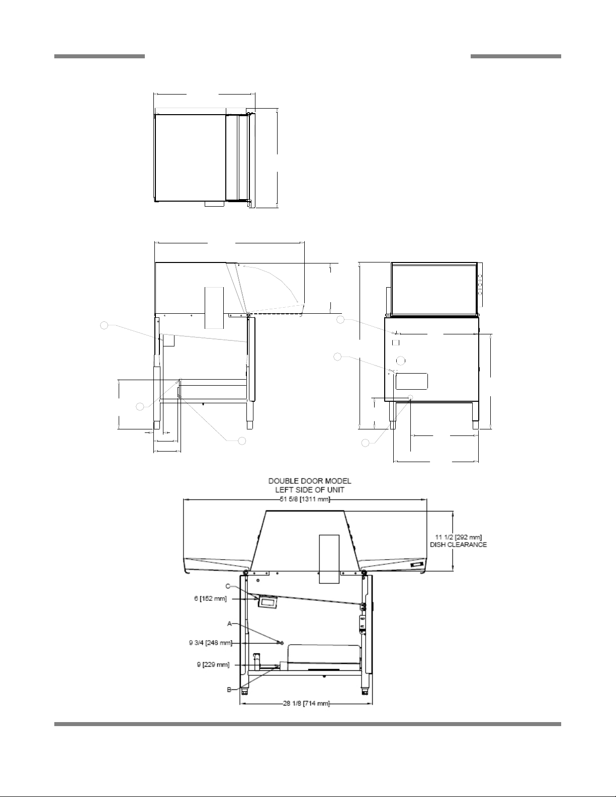
FRAME DIMENSIONS:
WIDTH (622.3mm) 24 1/2”
DEPTH (641.35mm) 25 1/4”
DEPTH, WITH FRONT DOOR OPEN (933.45mm) 36 3/4”
HEIGHT (990.6mm) 39”
MAXIMUM WASH
CHAMBER CLEARANCE (292.1mm) 11 1/2”
FRAME DIMENSION (DOUBLE DOOR):
WIDTH (622.3MM) 24 1/2”
DEPTH (714.375MM) 28 1/8”
DEPTH, WITH DOOR OPEN (1311.275MM) 51 5/8”
HEIGHT (990.6MM) 39”
CHAMBER CLEARANCE (292.1MM) 11 1/2”
NOTE: Always refer to the machine data plate for specific
electrical and water requirements. The material provided on
this page is for reference only and may be subject to change
without notice.
Delta 5 Installation & Operation Manual 7610-003-37-08
Issued: 05-25-2007 Revised: 03-18-2014
SECTION 1: SPECIFICATION INFORMATION
DIMENSIONS
3
21 1/4
(540 mm)
17
(432 mm)
20
(508 mm)
C
A
21 1/4
(540 mm)
B
7 3/4
(197 mm)
39
(991 mm)
6 3/4 (171 mm)
6 (152 mm)
12 1/4
(311 mm)
36 3/4
(933 mm)
24 1/2
(622 mm)
25 1/4
(642 mm)
C
A
B
3 (76 mm)
A - Incoming Water Connection
B - Drain Connection - 2" IPS
C - Electrical Connection Point
NOTE: All vertical dimensions are
at lowest point due to adjustable
bullet feet and may be raised an
additional 2 3/4".
11 1/2
(292 mm)
DISH
CLEARANCE

4
SECTION 2:
INSTALLATION & OPERATION INSTRUCTIONS
VISUAL INSPECTION: Before installing unit check container and machine for damage. A damaged container may be an
indication of damage to the machine. If there is any type of damage to both container and unit, do not throw away the container.
The dishmachine has been inspected at the factory prior to shipping and is expected to arrive in new, undamaged condition.
However, rough handling by carriers or others may result in damage to the unit while it is in transit. If such a situation occurs,
do not return the unit to the manufacturer. Instead, contact the carrier and ask them to send a representative to the site to
inspect the damage, and request that an inspection report be completed. Contact the carrier within 48 hours of receiving the
machine (to report possible freight damage) and the dealer from whom the unit was purchased.
UNPACKING THE DISHMACHINE: Remove the machine from the container and inspect it for any missing parts. If a part is
missing, contact manufacturer immediately.
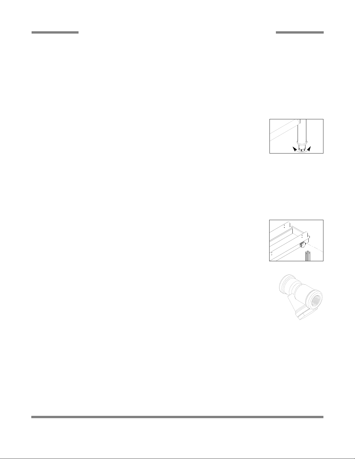
LEVEL THE DISHMACHINE: The dishmachine is designed to operate while level. This is important to
prevent any damage to the machine during operation and to ensure the best results possible. The unit
is equipped with adjustable bullet feet which can be turned using a pair of pliers. Verify the unit is level
from front to back and side to side before making any electrical or plumbing connections.
PLUMBING THE DISHMACHINE:All plumbing connections must be made to adhere to local, state,
territorial and national codes. The installing plumber is responsible for ensuring the incoming water lines are flushed of debris
prior to connecting to the machine. Note that chips and materials from cutting processes can become lodged in the solenoid
valves and prevent them from opening or closing. Any valves that are found to be fouled or defective because of foreign
matter left in the water line, and any subsequent water damage, are not the responsibility of the manufacturer.
A water hardness test should be performed to determine if the HTS-11 (scale prevention & corrosion control) needs to be
installed. If water hardness is higher than 5 GPG, the HTS-11 will need to be installed. Please contact manufacturer to purchase
the HTS-11.
CONNECTING THE DRAIN LINE: This dishmachine drain requires a minimum 2” NPT piping that
is pitched at least 1/4” per foot. There must also be an air gap between the machine drain line and
the floor sink or drain. If a grease trap is required by code, it should have a flow capacity of
5 gallons per minute.
WATER SUPPLY CONNECTION: Install the water supply line (1/2” NPT minimum) to the dishmachine
line y-strainer using copper pipe. It is recommended that a water shut-off valve be installed between
the main supply and the machine to allow for service. The water supply line must be capable of 20 ±5
PSI “flow” pressure at the recommended temperature as indicated on the data plate.
PRESSURE REGULATOR: In areas where the water pressure fluctuates or is greater than the
recommended pressure, it is suggested that a water pressure regulator be installed. This dishmachine
does not come with a water pressure regulator as standard equipment.
SHOCK ABSORBER: It is recommended that a shock absorber (not supplied) be installed in the
incoming water line. This prevents water hammer (hydraulic shock)—induced by the solenoid valve as
it operates—from causing damage to the equipment.
PLUMBING CHECK: Slowly turn on the water supply to the machine after connecting the incoming fill line and drain line.
Check for leaks and repair as required. Leaks must be repaired prior to operating the machine.
Delta 5 Installation & Operation Manual 7610-003-37-08
Issued: 05-25-2007 Revised: 03-18-2014
SECTION 2: INSTALLATION & OPERATION INSTRUCTIONS
INSTALLATION INSTRUCTIONS
5
Frame with Adjustable Foot
Drain Connection
Y-Strainer
Raise
Lower

Delta 5 Installation & Operation Manual 7610-003-37-08
Issued: 05-25-2007 Revised: 03-18-2014
6
ELECTRICAL POWER CONNECTION: DISCONNECT ELECTRICAL POWER SUPPLIES & TAG OUT IN ACCORDANCE
WITH APPROPRIATE PROCEDURES & CODES AT THE DISCONNECT SWITCH TO INDICATE THE CIRCUIT IS BEING
SERVICED.
Electrical and grounding conductors must comply with the applicable portions of the National Electric Code ANSI/NFPA 70
(latest edition) and/or other electrical codes.
Refer to the machine’s data plate for machine operating requirements,
machine voltage, total amperage & serial number.
Remove the connection box lid to install the incoming power lines. Install 1/2”
conduit into the pre-punched holes in the back of the connection box. Route the
power wires and connect to the power block and grounding lug. Install the service
wires (L1 and N) to the appropriate terminals as they are marked on the terminal
block. Install the grounding wire into the lug provided. Wires should be firmly secured
in place.
It is recommended that “De-Ox” or another similar anti-oxidation agent be used on
all voltage connections.
VOLTAGE CHECK: Ensure that the machine is off and apply power to the machine.
Check the incoming power at the terminal block and ensure it corresponds to
the voltage on the machine data plate. Do not run the dishmachine if the voltage
is too high or too low. Shut off the service breaker and mark it as being for the
dishmachine. Advise all personnel of the location of the service breaker. Replace
all covers and tighten the screws.
NOTE: Always refer to the machine data plate for specific electrical and water requirements. The material provided on
this page is for reference only and may be subject to change without notice.
Ground Lug
Power Block
SECTION 2: INSTALLATION & OPERATION INSTRUCTIONS
ELECTRICAL INSTALLATION INSTRUCTIONS

OPERATIONAL START-UP AND CHECK: Before proceeding with the start-up, verify the following:
1. Open the door and verify that the sump strainer is correctly installed in the sump.
2. Verify that the drain stopper is in position.
3. Check that the plugs are securely screwed into the ends of the wash arm.
4. Check that the wash arm is securely screwed into the stationary base and that it rotates freely.
5. Check the levels in all chemical containers and replace if necessary.
INITIAL START-UP PROCEDURE:
1. Turn on dishmachine:
a) Turn on the incoming power to the machine at the circuit disconnect box.
b) Turn on the dishmachine by pressing the ON/OFF button. The red light will come on.
c) Check voltage at incoming terminals L1& L2. The voltage measured at these points should match data plate voltage.
d) If voltages are in required range, close the control box cover.
2. Fill the rinse booster heater with water:
a) Before the heater element can be energized, the rinse booster heater must be initially filled with water. Damage to the
heater element will occur if the element is not submerged in water. To initially fill the booster heater with water:
i) Press and hold the FILL button to turn on the incoming water solenoid valve. Continue holding the button until water is
heard entering the wash chamber through the airgap, then release the button. The rinse booster heater is now filled
with water.
ii) Turn off the unit by pressing the on/off switch.
3. Enable heater element:
a) For the initial start-up only, the heater element must be enabled. The machine is shipped from the factory with the heater
element disabled. This is done to ensure that the heater element is not damaged by energizing the element without the
element being submerged in water. To enable the heater element:
i) Remove the booster heater cover panel.
ii) Connect the tagged white/blue wires.
iii) Replace heater cover.
iv) Press the on/off switch, heaters will energize to maintain booster heater temperature.
Note: Water must be in the sump while the machine is running to avoid running the pump dry and causing damage to the pump
seal.
4. Adjust dishmachine fill level:
a) If the water level is not between the lines on the drain standpipe, it will require adjustment. Check to ensure that the
recommended water pressure is being supplied to the machine (20 ±5 PSI is required). If the water pressure is correct,
the electronic timer will need adjustment. Use the following steps to adjust the fill time.
i) Open control box cover.
ii) Adjust fill time as per instructions found in this section.
iii) Open and close the door to run a cycle, then check the water level. Adjust as necessary then close the
control box cover.
NOTE: The machine must run a complete cycle to drain and fill. If the machine is not allowed to drain, the water will build up
inside the tub. After the initial fill, the rinse water for the current cycle will become the wash water for the next cycle.
The dishmachine is now ready to proceed with dishwashing.
Delta 5 Installation & Operation Manual 7610-003-37-08
Issued: 05-25-2007 Revised: 03-18-2014
7
SECTION 2: INSTALLATION & OPERATION INSTRUCTIONS
OPERATION INSTRUCTIONS

Delta 5 Installation & Operation Manual 7610-003-37-08
Issued: 05-25-2007 Revised: 03-18-2014
8
WARNING: Certain materials, including silver, silver plate, aluminum and pewter, are attacked by sodium hypochlorite
sanitizers (bleach).
PREPARING DISHES: Proper preparation of ware is essential for the smooth and efficient operation of the dishmachine,
resulting in fewer rewashes and using less detergent.
The following steps should be followed to ensure good results:
1. Remove all scraps and soil into a garbage can.
2. Separate and pre-soak silverware.
3. Separate and pre-soak the egg and casserole dishes.
4. Scrape all ware with a brush or spatula.
5. Flush cups, bowls and glasses with running water.
6. Prewash dishware by soaking or spraying with a pre-rinse hose.
7. Place dishes and cups in dish rack. Cups should be upside down so they don’t hold water.
8. Place glasses and flatware in their respective racks. Scatter flatware loosely in rack. Glasses should be placed upside
down in a properly sized rack. For optimal results, flatware should be washed twice, the first being horizontal, the second in
a special rack to hold flatware vertical.
DAILY MACHINE PREPARATION: Before proceeding with start-up, verify the following:
1. Open door and verify that the sump strainer is in place in the sump.
2. Verify that the drain stopper is in position.
3. Check that the plugs are securely screwed into the ends of all wash arms.
4. Check that the wash arms are securely screwed into the stationary bases and rotate freely.
5. Check levels in all chemical containers and replace if empty.
6. For initial fill, close doors and depress the “FILL” switch to the “FILL” position.
WASHING A RACK OF WARE:
1. Open doors, place a full rack into the machine, and close doors. Push the start switch and hold until unit starts
(about 2 seconds).
2. After cycle is completed open doors and remove rack.
3. Repeat steps A and B.
SHUT DOWN AND CLEANING:
1. At the end of mealtime, move the “ON/OFF” switch to the “OFF” position.
2. Open doors and manually remove drain stopper to drain the unit.
3. Remove and clean upper and lower wash arms.
4. Remove and clean the sump strainer.
SECTION 2: INSTALLATION & OPERATION INSTRUCTIONS
OPERATION INSTRUCTIONS

Delta 5 Installation & Operation Manual 7610-003-37-08
Issued: 05-25-2007 Revised: 03-18-2014
WARNING: CHLORINE-BASED SANITIZERS CAN BE DETRIMENTAL TO THE MACHINE IF THE
CHEMICAL SOLUTION IS TOO STRONG. SEE A CHEMICAL PROFESSIONAL
TO ENSURE THE DISPENSER IS SET UP CORRECTLY.
This equipment is not recommend for use with deionized water or other aggressive fluids.
Use of deionized water or other aggressive fluids will result in corrosion and failure of materials and
components and will void the manufacturer's warranty.
TO PREPARE CHEMICAL FEEDER PUMPS FOR OPERATION:
The Delta 5 dismachines are supplied with detergent, rinse
additive and sanitizer dispensing chemical feeder pumps. Locate the open ends of the chemical tubes with the tube stiffeners
and place each one in the appropriate container.
Red Tubing = Detergent Blue Tubing = Rinse Aid White Tubing = Sanitizer
PRIMING CHEMICAL FEEDER PUMPS: Chemical feeder pumps need priming when the machine is first installed or if for
some reason the chemical lines have been removed and air is allowed to enter.
CAUTION: Water must be in the sump and wash tank prior to the dispensing of chemicals.
Sanitizer in concentration is caustic and may cause damage without dilution.
1. Verify that the proper chemical tube stiffener inlet is in the proper container.
2. Use the prime switches located on the control panel at the bottom of the unit to prime each pump.
The switches are clearly marked as to what chemical feeder pump they are assigned to.
3. To prime the pumps, hold the switch in the momentary position until chemical can be observed entering the sump.
4. Detergent is dispensed as required during the wash cycle by the universal timer. The amount of detergent may need to be
increased or decreased depending on water quality and type of detergent.
5. Rinse additive is dispensed as required into the final rinse. The amount of rinse aid may need to be adjusted depending on
water hardness and results.
6. Sanitizer (either chlorine or iodine) is dispensed into the final rinse. The amount of sanitizer may need to be adjusted
depending on the concentration and type of sanitizer used.
7. Please refer to the next page for instruction on adjusting the chemical feeder pumps on the universal timer.
WARNING: Some of the chemicals used in dishwashing may cause chemical burns if they
come in contact with skin. Wear protective gear when handling these chemicals.
If any skin comes in contact with these chemicals, immediately follow the instructions
provided with the chemicals for treatment.
9
SECTION 2: INSTALLATION & OPERATION INSTRUCTIONS
CHEMICAL DISPENSING EQUIPMENT

DETERGENT CONTROL: Detergent usage and water hardness are two factors that contribute greatly to how efficiently this
dishmachine will operate. Using detergent in the proper amount can become a source of substantial savings. A qualified water
treatment specialist can relate what is needed for maximum efficiency from the detergent.
1. Hard water greatly affects the performance of the dishmachine, causing the amount of detergent required for washing
to increase. If the machine is installed in an area with hard water, the manufacturer recommends the installation of water
treatment equipment.
2. Deposited solids from hard water can cause spotting that will not be removed with a drying agent. Treated water will reduce
this occurence.
3. Treated water may not be suitable for use in other areas of operation and it may be necessary to install a water treatment
unit for the water going to the dishmachine only. Discuss this option with a qualified water treatment specialist.
4. Dishmachine operators should be properly trained in how much detergent is to be used per cycle. Meet with a water
treatment specialist and detergent vendor to discuss a complete training program for operators.
5. Certain dishmachine models require that chemicals be provided for proper operation and sanitization. Some models
may require the installation of third-party chemical feeders to introduce those chemicals to the machine. The manufacturer
does not recommend or endorse any brand name of chemicals or chemical dispensing equipment. Contact a chemical
distributor for questions.
6. Some dishmachines come equipped with integral solid detergent dispensers. These dispensers are designed to accommodate
detergents in a certain-sized container. If applicable, relate this to a chemical distributor upon first contacting them.
7. Water temperature is an important factor in ensuring that the dishmachine functions properly, and the machine's data plate
details what the minimum temperatures must be for the incoming water supply, the wash tank and the rinse tank. If minimum
requirements are not met, there is a possibility that dishes will not be clean or sanitized.
8. Instruct dishmachine operators to observe the required temperatures and to report when they fall below the minimum
allowed. A loss of temperature can indicate a larger problem—such as a failed heater—or could indicate that the hot water
heater for the operation is not up to capacity and a larger one may need to be installed.
10
Delta 5 Installation & Operation Manual 7610-003-37-08
Issued: 05-25-2007 Revised: 03-18-2014
SECTION 2: INSTALLATION & OPERATION INSTRUCTIONS
DETERGENT CONTROL

11
SECTION 3:
PREVENTATIVE MAINTENANCE
 Loading...