

Page 1

DELTA 5
CHEMICAL SANITIZING DISHMACHINE
SERVICE MANUALSERVICE MANUAL
Visit Jackson on the Internet at:
www.jacksonmsc.com
October 22, 2001 P/N 7610-002-50-40 (REVSION A)
Page 2

TABLE OF CONTENTS
SECTION TITLE/DESCRIPTION PAGE
I. Specifications of the Delta 5 1
II. Installation Instructions 2
III. Operation Instructions 3
IV. Programming Instructions 6
V. Programming Chart for the Delta 5 7
VI. Troubleshooting Guide 8
VII. Dimensions 9
VIII. Parts Section
Control Box Assembly 10
Chemical Feeder Pump Assembly 12
Electrical Connection Box Assembly 13
Frame Weldment/Hood Assembly 14
Tub Components 15
Spillway Weldment Assembly/Pump Suction Hose 16
Wash Arm Assembly 17
Upper Halo Assembly 18
Drain Solenoid Assembly 19
Booster Tank Assembly 20
Incoming Plumbing Assembly 21
Solenoid Valve Repair Parts 22
Pump and Motor Assembly 23
Booster Tank Dishcarge Hose/Fill Tube Weldment Assembly 24
Strainers 25
Door Components 26
Front Panel Assembly 27
IX. 8 - Pin Harness Diagram 30
X. Electrical Diagram (115V, 60 Hz, 1 Phase) 31
i
Page 3

SPECIFICATIONS OF THE DELTA 5
OPERATING CAPACITY
RACKS PER HOUR 40
DISHES PER HOUR 1000
GLASSES PER HOUR 1000
OPERATING CYCLES (SECONDS)
NORMAL CYCLE:
WASH TIME 45
RINSE TIME 25
TOTAL CYCLE TIME 90
HEAVY CYCLE:
PREWASH TIME 20
WASH TIME 45
RINSE TIME 25
TOTAL CYCLE TIME 130
WASH TANK CAPACITY (GALLONS) 1.2
WASH PUMP CAPACITY (GALLONS PER MINUTE) 61
OPERATING TEMPERATURES (FAHRENHEIT):
WASH (MINIMUM) 120
WASH (RECOMMENDED) 140
RINSE (MINIMUM) 120
RINSE (RECOMMENDED) 140
ELECTRICAL REQUIREMENTS:
WASH PUMP MOTOR HORSEPOWER 1/2
RINSE BOOSTER TANK HEATER ELEMENT 2 KW
VOLTS FREQUENCY PHASE TOTAL AMP LOAD
115 60 HZ 1 24.1
WATER REQUIREMENTS:
WATER LINE SIZE (I.P.S.) 1/2”
DRAIN LINE SIZE (I.P.S.) 2”
FLOW PRESSURE (OPTIMUM) 20 PSI
MINIMUM CHLORINE REQUIRED 50 PPM
FRAME DIMENSIONS:
WIDTH 24.25”
DEPTH 25.25”
DEPTH, WITH FRONT DOOR OPEN 38”
HEIGHT 41”
MAXIMUM WASH CHAMBER CLEARANCE 11.5”
1
Page 4

INSTALLATION INSTRUCTIONS
VISUAL INSPECTION: Before installing the unit, check the container and the machine for any damage. A damaged container
could be an indication of damage to the unit. If there is damage to
both the container and the unit, DONOT throw away the container. The dishmachine has been inspected and packed at the factory with the expectation that it will arrive to you in new, undamaged
condition. However, rough handling by carriers or others may
damage the unit while in transit. If this situation does occur, do not
return the unit to Jackson; instead contact the carrier and ask
them to inspect the damage to the unit and to complete an inspection report. You must contact the carrier within 48 hours of receiving the machine. Also, contact the dealer you purchased the
machine through.
UNPACKING THE DISHMACHINE: Remove the machine from
the container and inspect for any missing parts. If an item appears
to be missing, contact Jackson immediately to report it.
LEVEL THE DISHMACHINE: The dishmachine(s) covered in this
manual are designed to operate on a level surface. Ensure that
the machine is level from side to side and from front to back;
adjust the unit’s bullet feet as required. Failure to level the dishmachine may cause decreased washing performance.
PLUMBING THE DISHMACHINE: All plumbing connections must
comply with all applicable local, state and national plumbing
codes. The plumber is responsible for flushing the incoming water
line prior to connecting it to remove all foreign debris that may get
trapped in the valves or cause an obstruction. Any valves that are
fouled by matter left in the water line and the expenses resulting
are not the responsibility of the manufacturer.
ELECTRICAL POWER CONNECTION: Electrical and grounding
connections must comply with all applicable portions of the
National Electric Code (ANSI/NFPA 70) and/or other electrical
codes that may apply.
Disconnect the electrical power supply and place a safety tag at
the disconnect switch to indicate that you are working on the circuit.
The dishmachine data plate is located on the left front corner of
the machine. Refer to this data plate for information concerning
the unit’s specific electrical requirements.
To install the incoming power lines, open the connection box by
removing the connection box lid. Install 1/2” coduit into the prepunched holes in the back of the connection box. Route the power
wires and connect to the power block and grounding lug. Install
the service wires (L1 and N) to the appropriate terminals as they
are marked on the terminal block. Install the grounding wire into
the lug provided. Wires should be firmly secured in place.
It is recommended that “De-Ox” or another similar anti-oxidation
agent be used on all voltage connections.
VOLTAGE CHECK: Ensure that the machine is off and apply
power to the machine. Check the incoming power at the terminal
block and ensure it corresponds to the voltage on the machine
data plate. Do not run the dishmachine if the voltage is too high or
too low. Shut off the service breaker and mark it as being for the
dishmachine. Advise all personnel of the location of the service
breaker. Replace all covers and tighten the screws.
CONNECTING THE DRAIN LINE: The DELTA 5 drain requires a
minimum 2” IPS piping that is pitched at least 1/4” per foot. There
must also be an air gap between the machine drain line and the
floor sink or drain. If a grease trap is required by code, it should
have a flow capacity of 5 gallons per minute.
WATER SUPPLY CONNECTION: Install the water supply line
(1/2” IPS minimum) to the dishmachine line strainer using copper
pipe. It is recommended that a water shut-off valve be installed
between the main supply and the machine to allow for service.
The water supply line must be capable of 20 PSI “flow” pressure
at the recommended temperature as indicated on the data plate.
In areas where the water pressure fluctuates or is greater than the
recommended pressure, it is suggested that a water pressure regulator be installed. The DELTA 5 does not come with a water pressure regulator as standard equipment.
It is also recommended that a shock absorber (not supplied with
the DELTA 5) be installed in the incoming water line. This prevents
line hammer (hydraulic shock), induced by the solenoid valve,
which can cause damage to the equipment.
PLUMBING CHECK: Slowly turn on the water supply to the
machine after connecting the incoming fill line and drain line.
Check for leaks and repair as required. Leaks must be repaired
prior to placing the machine in operation.
2
Page 5

OPERATION INSTRUCTIONS
OPERATIONAL START-UP AND CHECK: Before proceeding
with the start-up, verify the following:
1. Open the door and verify that the sump stariner is correctly
installed in the sump.
2. Verify that the drain stopper is in position.
3. Check that the plugs are securely screwed into the ends of the
wash arm.
4. Check that the wash arm is securely screwed into the stationary base and that it rotates freely.
5. Check the levels in all chemical containers and replace if necessary.
INSTALLATION/INITIAL START-UP PROCEDURE:
1. Turn on dishmachine
a) Turn on the incoming power to the machine at the cir-
cuit disconnect box. The display will indicate OFF.
b) Turn on the dishmachine by pressing the ON/OFF but-
ton. The display will indicate HEATER DISABLED.
2. Fill rinse booster heater with water
a) Before the heater element can be energized, the rinse
booster heater must be initially filled with water. Damage to the
heater element will occur if the element is not submerged in water.
To initially fill the booster heater with water:
i) Press and hold the PROGRAM button.
ii) The display will indicate ENTER CODE.
Press CYCLES, DELIME, ENTER and CYCLES.
iii) The display will indicate PROG DRAIN/FILL.
Repeatedly press the PROGRAM button until ENGINEERING is
displayed. Press ENTER to enter the engineering mode.
iv) Repeatedly press the PROGRAM button
until PRESS ENTER TO OPEN FILL is displayed.
v) Press and hold the ENTER button to turn on
the incoming water solenoid valve. Continue holding the button
until you hear water entering the wash chamber through the airgap, then release the button. The rinse booster heater is now filled
with water.
vi) Repeatedly press the PROGRAM button
until PRESS ENTER TO EXIT is displayed. Press the ENTER button to exit the ENGINEERING mode.
3. Enable heater element
a) For the initial start-up only, the heater element must be
enabled. The machine is shipped from the factory with the heater
element disabled. This is done to ensure that the heater element
is not damaged by energizing the element without the element
being submerged in water. To enable the heater element:
Note: After completing step 2.v., you will still be in the pro gramming mode. However, if you do not press any keys for
45 seconds, the controller will automatically log out of the
programming mode. Follow steps 2.i. and 2.ii. above to reenter the programming mode.
i) Repeatedly press the PROGRAM button until
SYSTEM is displayed. Press ENTER to enter the SYSTEM programming mode.
ii) Repeatedly press the ENTER button until
HEATER ELEMENT IS DISABLED is displayed.
iii) Press the NORMAL button to change the
display to HEATER ELEMENT IS ENABLED.
iv) Press the PROGRAM key to exit the SYSTEM programming mode. You should hear the heater contactor
close.
v) Repeatedly press the PROGRAM button until
EXIT is displayed. Press the ENTER button to exit the programming mode.
vi) The display will indicate HEATING WATER.
4. Adjust dishmachine fill level
a) Once the temperature in the rinse booster heater has
reached its preset value, the incoming water solenoid valve will
open to fill the wash tank with water (FILLING and the time
remaining for the will be displayed during the fill sequence).
b) The display will then indicate OPEN DOOR.
c) Open the door and observe the water level in the wash
tank sump. The water level should be between the two score lines
on the drain stopper.
d) If the water level is not satisfactory, drain the sump by
lifting the drain stopper. Close the door. Enter the programming
mode and adjust the fill time as necessary (PROG DRAIN/FILL
menu). Press the AUTO FILL button to refill the wash tank. Open
the door and observe the water level. Repeat these steps until the
proper water level is obtained.
5. Adjust dishmachine drain time
a) At the very end of the drain cycle, open the doors to
interrupt the cycle. Observe the sump area. All water from the
wash cycle should be drained from the wash tank sump.
b) In the programming section, adjust the DRAIN time
(PROG DRAIN/FILL menu) as necessary. Allow enough time for
the machine to completely drain before the rinse begins. Avoid
making the drain time too long, which will unnecessarily lengthen
the total cycle time.
3
Page 6

OPERATION INSTRUCTIONS (CONTINUED)
6. Adjust dishmachine flush time
a) The FLUSH will use fresh water to rinse out the deter-
gent residue and soils in the wash tank before the rinse begins.
The FLUSH time is the time that the drain valve will remain open
at the beginning of the FILL cycle. Avoid making the flush time too
long, which will increase the water usage per machine cycle.
b) In the programming section, increase or decrease the
FLUSH time (PROG DRAIN/FILL menu) as necessary.
7. Measure and adjust chemical concentrations.
8. Check all water and drain fittings for leaks.
9. Instruct machine operators on proper cleaning and operating
procedures.
GENERAL OPERATION SEQUENCE:
CAUTION: Water must be in the wash tank sump while the
wash pump is running in order to avoid damage to the pump
seal.
Close the machine's door. Turn on the machine by pressing the
PUSH ON/OFF button on the front panel. The display will indicate
HEATING WATER while the rinse water is heated in the booster
heater. This heating may take several minutes, depending on how
long the machine has set idle.
When the water in the booster heater reaches the specified temperature, the machine will automatically fill the wash sump with
water (FILLING and the time remaining for filling will be indicated
on the display). The minimum water level should be between the
two score lines on the drain stopper. To adjust the water level, see
programming instructions. During this initial fill, the detergent dispensing pump will run to dispense into the wash tank sump.
The display will indicate OPEN DOOR. Open the door and insert
a rack of soiled dishes. The display will indicate CLOSE DOOR.
Close the door. The display will indicate PRESS START TO
START CYCLE. At any time between cycles, the operator can
press select the NORMAL or HEAVY cycles by pressing the
appropriate button on the keypad. The default cycle is the normal
cycle. When either of these cycle keys is pressed, the display will
momentarily display the selection. The cycle will begin when the
PUSH TO START button on the front panel is pressed.
At the start of the cycle, a PREWASH sequence is initiated and
the wash pump is turned on. The length of this PREWASH
sequence is 20 seconds. PREWASH and the time remaining will
be displayed on the first line of the display. The TEMPERATURE
of the wash water will be displayed on the second line of the display.
At the end of the prewash sequence, if the wash tank water temperature is less than 120°F, or if the HEAVY cycle has been
selected, the machine will drain the wash water, and refill the
sump with fresh, heated water from the booster tank. The display
will indicate DRAINING, FLUSH and FILLING and will countdown
the time remaining for each during these steps. Detergent will be
dispensed during the filling sequence.
If the detergent dispensingtime is longer than the fill time, the
incoming water solenoid valve will be opened for one second at
the completion of the detergent dispensing, in order to flush out
any remaining detergent from the air gap. No rinse aid or sanitizer are dispensed. At the end of the prewash sequence, if the temperature of the wash water is greater than 120°F and the NOR MAL cycles was selected, these steps are skipped and control
goes directly to the washing sequence.
During the washing sequence, the wash pump is turned on.
WASHING and the time remaining will be displayed on the first
line of the display. The TEMPERATURE of the wash water will be
displayed on the second line of the display. If the length of the
DETERGENT WASH is longer than the length of DETERGENT
PREWASH, the detergent dispenser pump will run for the difference in these time values, dispensing additional detergent into the
wash tank sump. The length of the wash cycle is 45 seconds.
At the end of the wash cycle, if the temperature in the rinse booster tank has not reached 120°F (regardless of the rinse tank temperature setting), the wash time will be extended until the 120 ° is
reached, or three minutes, whichever is shorter. The display will
indicate EXTENDED WASH.
At the completion of the wash cycle, the machine will drain the
wash water, and refill the sump with fresh, heated water from the
booster tank. The display will indicate DRAINING, FLUSH and
FILLING and will countdown the time remaining for each during
these steps. During the FILLING sequence, rinse aid and sanitizer are dispensed.
The rinsing sequence now begins. RINSING and the time remaining will be displayed on the first line of the display. The TEMPERATURE of the rinse water will be displayed on the second line of
the display.
The completion of the rinse sequence is the end of the cycle, and
the display will indicate OPEN DOOR. Detergent is now dispensed into the wash tank sump for the next wash cycle. Open the
door, remove the clean dishes, load a rack of soiled dishes, close
the door and press the start button to start the next cycle. If the
next cycle is started before the completion of the detergent dispensing, the display will indicate DETERGENT DISPENSE, and
countdown the time remaining until the cycle will automatically
begin.
If the door is opened at any time during a cycle, CLOSE DOOR
will be displayed. The cycle will restart at the beginning of the prewash sequence when the door is closed again.
The cycle counter will only increment when cycles are fully completed. To display the number of cycles completed, between
cycles, press the CYCLES button on the keypad. Then number of
NORMAL cycles completed will be displayed. Press the CYCLES
button again to display the number of completed HEAVY cycles.
DETERGENT PREWASH - The run time of the detergent dispensing pump before the prewash sequence which controls the
amount of detergent dispensed.
4
Page 7

OPERATION INSTRUCTIONS (CONTINUED)
DETERGENT WASH - The run time of the detergent dispensing
pump before the wash sequence which controls the amount of
detergent dispensed.SANITIZER - The run time of the sanitizer
dispensing pump before the rinse sequence which controls the
amount of sanitizer dispensed.
RINSE TANK TEMPERATURE - When the water in the rinse
water booster heater reaches this temperature value, the heating
element will be turned off.
SHUTDOWN AND CLEANING: To turn off the machine, press the
ON/OFF button. The machine will automatically drain (TURNING
OFF will be displayed) and then will turn off (OFF will be displayed).
Remove, clean and install the lower wash arm.
Remove, clean and install the four upper spray nozzles.
Remove, clean and install the accumulator strainer.
PRIMING THE CHEMICAL DISPENSING PUMPS: To prime the
chemical feeder pumps that dispense the detergent, rinse aid and
sanitizer chemicals, press and hold the corresponding prime but ton on the keypad. The machine must be idle (between cycles) for
these prime buttons to be active.
DELIMING OPERATIONS: The DELTA 5 machine has a pre-programmed delime sequence which will lead the operator through
the steps required to properly delime the machine.
To begin, the machine must be OFF. Press and hold the DELIME
button on the keypad. The machine will automatically fill with fresh
water (FILLING will be indicated on the display). The display will
then indicate to OPEN DOOR - ADD LIME-A-WAY (deliming
chemical agent). Open the doors and add the delime chemical
agent. The display will indicate CLOSE DOORS TO START
DELIME. When the doors are closed, the wash pump will turn on
to circulate the delime agent throughout the machine. At any time,
the doors can be opened in order to inspect the inside of the
machine. The wash pump will restart when the doors are closed.
The display will indicate PRESS DELIME TO STOP CYCLE.
When the DELIME button on the keypad
5
Page 8

PROGRAMMING INSTRUCTIONS
To access the programming mode, the machine must be ON, and
idle (between cycles). Press and hold the PROGRAM button on
the keypad. The display will prompt to ENTER CODE. At this
prompt, enter the keys corresponding to the access code. Once in
the programming mode, the PROGRAM button is used to scroll
between the programming catagories, the ENTER button is used
to select a program section or parameter. To change the value of
the parameter, use the HEAVY button to decrease the value of the
parameter, and the NORMAL button to increase the value. To confirm a change to a programmable vale, press the ENTER button.
To abort or escape out of a change, press the PROGRAM button.
Once in the programming mode, if there have been no keypad
inputs for approximately 45 seconds, the system will automatically exit out of the programming mode.
All time adjustments are in minutes and seconds (minutes:seconds).
The following parameters can be adjusted in the programming
mode:
1. In the PROG(RAM) DRAIN/FILL section:
a) FILL TIME - Length of fill cycles. The minimum water
level should be between the score lines of the drain stopper.
b) FLUSH TIME - Time of overlap between the drain and
fill times.
c) DRAIN TIME - Time that the drain is open after the
wash cycle.
2. In the PROG(RAM) CHEMICAL section:
4. The ENGINEERING section is used when trouble-shooting
problems with the machine. In the ENGINEERING section:
a) TOTAL WASH CYCLES - This counter accumulates
the total number of cycles which the machine has been run. It is a
total of all wash cycles and it cannot be reset.
b) PRESS ENTER TO:
i) RUN PUMP - Press and hold the ENTER button to run the wash pump motor. Release the ENTER button to
make it stop.
ii) OPEN DRAIN - Press and hold the ENTER
button to energize (open) the drain solenoid. Release the ENTER
button to de-energize the solenoid.
iii) OPEN FILL - Press and hold the ENTER button to energize (open) the fill water valve solenoid. Release the
ENTER button to de-energize the solenoid.
iv) EXIT - Press the ENTER button to exit the
ENGINEERING section.
5. RESET CYCLES - The system will prompt CLEAR COUNT(S)?
E(YES) or P(NO) to confirm the that the cycle counter is to be
reset. Press the ENTER button on the keypad to reset the counter
or press the PROGRAM button to exit without resetting the
counter.
6. EXIT - Press the ENTER button on the keypad to exit the programming mode.
a) DETERGENT PREWASH - The run time of the detergetn dispensing pump before the prewash sequence which controls the amount of detergent dispensed.
b) DETERGENT WASH - The run time of the detergent
dispensing pump before the wash sequence which controls the
amount of detergent dispensed.
c) RINSE AID - The run time of the rinse aid dispensing
pump before the rinse sequence which controls the amount of
rinse aid dispensed.
d) SANITIZER - The run time of the sanitizer dispensing
pump before the rinse sequence which controls the amount fo
sanitizer dispensed.
3. In the SYSTEM section:
a) ENABLE/DISABLE HEATER ELEMENT - Selects
whether or not the rinse water booster element can be energized.
The selection options are ENABLE or DISABLE.
b) RINSE TANK TEMPERATURE - When the water in
the rinse water booster heater reaches this temperature value, the
heating element shall be turned off.
c) DISPLAY IN FAHRENHEIT OR CELSIUS - Selects the
unit of measure for water temperature display.
6
Page 9
PROGRAMMING CHART FOR THE DELTA 5
Short Version
Press and hold PROGRAM (P) for 2 seconds.
Press CYCLES, DELIME, ENTER, CYCLES
CODE
****
Press ENTER Press ENTER Press ENTER
PROG DRAIN/FILL FILL TIME 0:07 FLUSH TIME 0:03 DRAIN TIME 0:06
Press PROGRAM Press ENTER Press ENTER
PROG CHEMICAL
DETERGENT 0:05
PREWASH
Press UP ARROW (NORMAL) to increase time settings
Press DOWN ARROW (HEAVY) to decrease time
DETERGENT 0:05
WASH
Press ENTER
Press ENTER
Press PROGRAM
SYSTEM
Press PROGRAM
RESET COUNTS CLEAR COUNTS?
Press PROGRAM
EXIT
Refer to IO manual for system programming
Press ENTER Press ENTER to clear counter back to zero
Press ENTER
Back to regular operation
RINSE AID 0:05 SANITIZER 0:05
7
Page 10
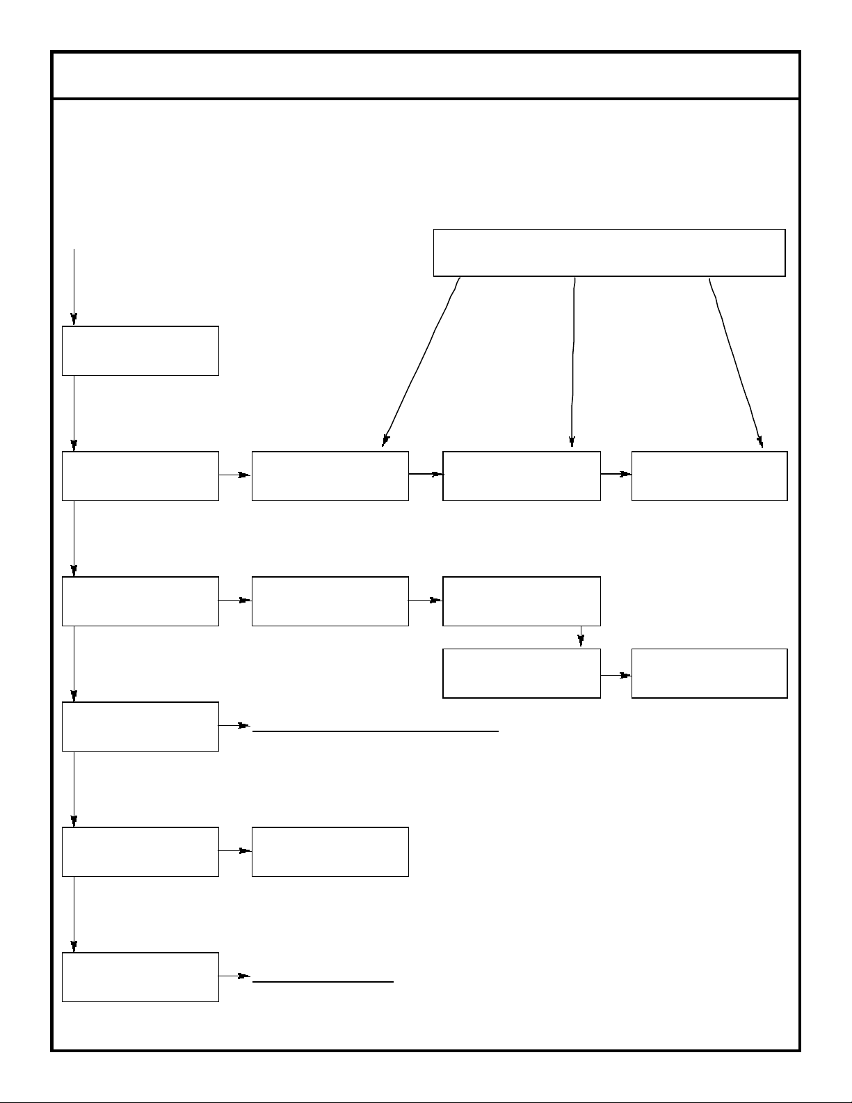
TROUBLESHOOTING GUIDE
The DELTA 5 dishmachine uses a microprocessor-based electronic controller to control function of the machine. The microprocessor
is pre-programmed at the factory to run a machine that is installed in a typical application. A LCD display is used to indicate the status
of the machine.
The electronic controller board with LCD display controls all timing functions. The controller board is connected to the interface board.
It sends signals to the interface board to turn components on and off. The remaining electrical control components in the machine are
connected to the interface board.
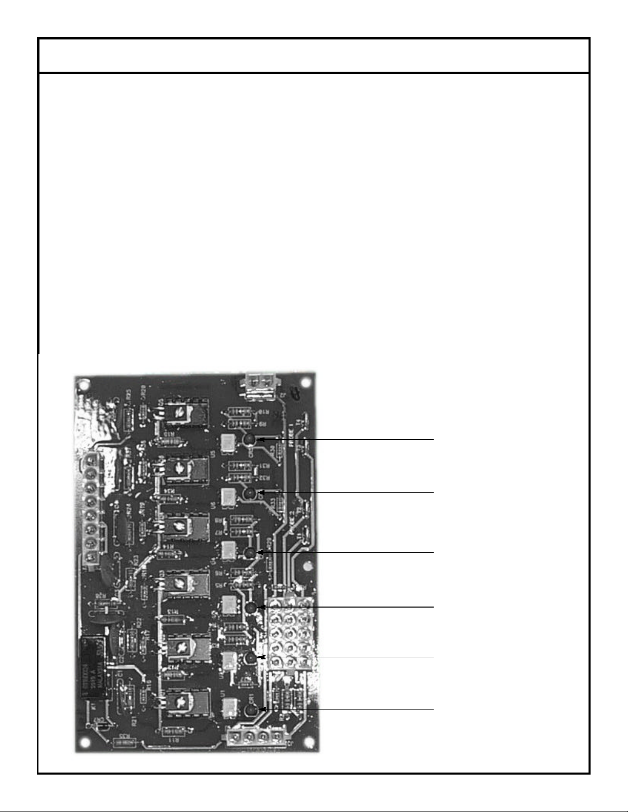
To aid in troubleshooting, the interface board contains six red LED (light emitting diodes). These diodes are illuminated whenever the
output signal to the corresponding control item is ON. The following example will illustrate the troubleshooting sequence that should be
used for all electrical control components. The wash pump runs at the first sequence of every cycle. The LED corresponding to the
wash pump motor contactor will be ON when the pump is to be On. If the LED is ON, and the pump motor is not running, measure the
voltage at the pump motor contactor soil (when the LED is on, meaning voltage should be applied to the coil from the interface board).
If there is no voltage, then replace the interface board. If there is voltage, then there is a problem in the pump motor and pump motor
contactor. If the display indicates that the machine is in a wash cycle, and both the pump motor is not running and the LED is not ON,
check the continuity of the cable that connects the controller board to the interface board. If continuity exists, replace the controller
board. If the controller board has been replaced and the problem still exists, replace the interface board.
The interface board contains six triacs, which are essentially electronic relays. Use a multimeter to verify that the interface board out put is supplying voltage to a control item (solenoid valve, peristaltic pump, motor contactor, etc.). During any troubleshooting, it is crit ical to remember that a 120 volt signal will always be measured at the outputs of the interface board (pins 1 through 8 on connector
J4) if the corresponding load (solenoid valve, peristaltic pump, motor contactor, etc.) is not connected to the output. To avoid false readings, the control item that is being tested must be connected to the interface board output.
Drain LED
Pump LED
Fill LED
Sanitizer LED
Rinse Aid LED
Detergent Fill LED
8
Page 11

DIMENSIONS
9
Page 12

CONTROL BOX ASSEMBLY
DELTA 5 Control Box Base
1 per machine
Mfg. No.: 5700-002-40-03
12
3 4
101112
Associated Hardware:
Locknut, 6-32 S/S Hex w/Nylon Insert 5310-373-03-00
Locknut, 10-24 S/S Hex w/Nylon Insert 5310-373-01-00
Locknut, 1/4”-20 S/S Hex w/Nylon Insert 5310-374-01-00
Screw, 6-32 x 3/8” Phillip Round Head 5305-171-02-00
10
789
56
Page 13

CONTROL BOX ASSEMBLY (CONTINUED)
2
1
Noise Filter, Corcom
5910-002-20-37
3
1
Interface Board
6680-002-16-81
5
1
Inner Control Panel
5700-002-21-71
6
1
Terminal Board
5700-021-70-70
8
1
6 Pole Fuse Holder
5920-002-42-13
6
Fuse, 1.5 AMP Fastblow 3AG
5920-002-44-12
10
1
Motor Contactor
5945-109-05-69
11
1
Relay
5945-002-45-20
2
2
Motor, Chemical Feeder Pump, 36 RPM
4320-111-35-14
3
1
Motor, Chemical Feeder Pump, 14 RPM
4320-111-35-13
5
1
Chemical Feeder Pump Kit
4320-121-37-10
6
1
Tubing, 1/4" OD x 120" Long, White
5700-011-37-13
8
1
Tubing, 1/4" OD x 120" Long, Blue
5700-011-37-17
1
Tubing, 1/4" OD x 5" Long, Red
5700-002-52-32
10
1
Tubing, 1/4" OD x 5" Long, White
5700-002-52-33
11
1
Tubing, 1/4" OD x 5" Long, Blue
5700-002-52-34
ITEM QTY DESCRIPTION MFG NO.
1 1 Control Box Weldment 5700-002-45-72
4 4 Circuit Board Holder 5940-002-21-87
7 1 Bracket, Fuse Strip Assembly 5700-002-42-60
9
12 1 Transformer 115V to 24V 5950-002-16-78
11
7
9
6
10
* Represents an item not shown.
8
5
5
5
2 2 3
1
4
ITEM QTY DESCRIPTION MFG NO.
1 1 Control Box Assembly Cover 5700-002-40-00
4 1 Drip Channel 5700-002-40-65
7 1 Tubing, 1/4" OD x 120" Long, Red 5700-011-37-15
9
*12 1 Stiffener 17 3/8" 5700-011-35-23
11
Page 14

CHEMICAL FEEDER PUMP ASSEMBLY
2
2
Screw, 8-32 x 3/8" Long, Phillipshead
5305-011-37-07
3
2
Screw, 8-32 x 1/2" Long Phillipshead
5305-011-37-06
5
1
Housing, Front
4320-111-37-08
6
4
Screw, 6-32 x 3/4" Long Phillips Panhead
5305-011-37-05
1
Chemical Feeder Pump Squeeze Tube - Detergent
5700-111-35-29
1
Chemical Feeder Pump Squeeze Tube - Rinse Aid
5700-111-35-29
1
Chemical Feeder Pump Motor (14 RPM) - Sanitizer
4320-111-35-13
2
1
5
3
4
ITEM QTY DESCRIPTION MFG NO.
1 1 Housing, Rear 4320-111-37-09
4 1 Roller, Anko 4320-111-36-70
6
1 Chemical Feeder Pump Squeeze Tube - Sanitizer 5700-011-76-41
1 Chemical Feeder Pump Motor (36 RPM) - Detergent 4320-111-35-14
1 Chemical Feeder Pump Motor (36 RPM) - Rinse Aid 4320-111-35-14
12
Page 15

ELECTRICAL CONNECTION BOX ASSEMBLY
2
1
Terminal Block
5940-500-09-61
3
1
Terminal Block Spacer
5700-011-40-05
1
Nut, 1" NPT Locking Heyco
5975-002-35-55
5
1
Locknut, 10-24 with Nylon Insert
5310-373-01-00
7
1
Electrical Connection Box Weldment
5700-002-45-69
1
Decal, Power Connection
9905-011-47-64
8
1
Electrical Connection Box Cover
5700-002-45-70
1
Decal, Warning to Disconnect Power
9905-100-75-93
8
1
2
3
4
7
ITEM QTY DESCRIPTION MFG NO.
1 1 Locknut, 6-32 with Nylon Insert 5310-373-03-00
5
6
4 1 Fitting, Straight Through, Liquidtite (1.375) 5975-002-30-67
6 1 Lug, Ground 5940-200-76-00
1 Decal, Copper Conductors Only 9905-011-47-35
1 Screw, 10-32 x 3/8" Long, Phillips Trusshead 5305-173-12-00
13
Page 16

FRAME WELDMENT/HOOD ASSEMBLY
2
1
Plate, Door Pivot (Right Side)
5700-002-55-95
3
1
Door Weldment
5700-002-45-65
5
1
Plate, Shock Mounting
5700-002-45-64
6
1
Fill Tube Weldment
5700-002-45-61
8
1
Door Dampener
5340-002-42-63
Delta 5 Frame Weldment
1 per machine
Ecolab No.: 96039748
Mfg. No.: 5700-002-4235
To order the Bullet Feet
4 per Frame Weldment
Ecolab No.: 96552666
Mfg. No.: 5340-108-01-03
Associated Hardware:
Locknut, 1/4”-20 S/S Hex Low Profile w/Nylon Insert 5310-374-02-00
Locknut, 1/4”-20 S/S Hex w/Nylon Insert 5310-374-01-00
Washer, S/S 1/4”-20 ID 5310-174-01-00
Bolt, 1/4”-20 x 1/2” Long 5305-274-02-00
Bolt, 1/4”-20 x 3/4” Long 5305-274-04-00
1
9
6
7
8
5
ITEM QTY DESCRIPTION MFG NO.
1 1 Hood Weldment 5700-002-44-36
2
3
4
4 2 Rack Rail Weldment 5700-002-45-67
7 1 Airgap Weldment 5700-002-45-60
9 1 Plate, Door Pivot (Left Side) 5700-002-45-62
14
Page 17

Stand Pipe Weldment
Mfg. No.: 5700-021-33-29
The entire Stand Pipe
Assembly may be
ordered using Mfg. No.:
5700-031-35-55.
TUB COMPONENTS
1 per machine
DELTA 5 Tub Weldment
1 per machine
Mfg. No.: 5700-002-45-50
Stand Pipe Stopper
1 per machine
Mfg. No.: 5700-021-35-54
Lower Manifold Weldment
1 per machine
Mfg. No.: 5700-002-45-51
Associated Hardware:
Bolt, Hex 3/8-16 x 1 1/4” 5305-276-10-00
Lockwasher, 3/8” 5311-276-01-00
Nut, Hex 3/8-16 S/S 5310-276-01-00
To order the O-ring or gasket, please refer to the items associated with the Modified Casting on the page entitled ‘Wash Arm
Assembly”.
15
Page 18

SPILLWAY WELDMENT ASSEMBLY/PUMP SUCTION HOSE
DELTA 5 Spillway Weldment
1 per machine
Mfg. No.: 5700-031-37-86
Associated Hardware:
Locknut, Hex w/Nylon Insert 5310-373-01-00
DELTA 5 Drain Seat Insert
1 per machine
Mfg. No.: 5700-021-34-38
DELTA 5 Spillway Gasket
2 per machine
Mfg. No.: 5700-111-34-52
DELTA 5 Pump Suction Hose
1 per machine
Mfg. No.: 5700-002-40-82
*To order the hose clamps for the Pump Suction Hose:
Mfg. No.: 4730-719-01-37
16
Page 19

WASH ARM ASSEMBLY
Order items 1 & 2 together using Mfg. No. 5700-021-39-23.
1
2
3
ITEM QTY DESCRIPTION MFG NO.
1 1 Wash Arm Weldment with End Plugs 5700-021-46-58
2 1 Wash Arm Bearing Assembly 5700-021-35-97
3 1 Modified Casting Wedge 5700-002-45-06
4 1 Manifold Gasket 5700-111-35-03
5 1 Manifold O-Ring 5330-111-35-15
17
4
5
Page 20

UPPER HALO ASSEMBLY
Upper Wash Halo Nozzle
3 per machine
Mfg. No.: 4730-002-45-22
DELTA 5 Upper Wash Halo Weldment
1 per machine
Mfg. No.: 5700-002-45-66
DELTA 5 Manifold Tube
1 per machine
Mfg. No.: 5700-002-40-71
DELTA 5 Upper Wash Halo Nozzle Receptical
3 per machine
Mfg. No.: 4730-002-45-21
Manifold O-Ring
1 per assembly
Mfg. No.: 5330-111-35-15
18
Page 21

DRAIN SOLENOID ASSEMBLY
DELTA 5 Solenoid Box
Mfg. No.: 5700-002-40-69
Order the following associated components with these numbers:
Fitting, Liquid Tight (.231 I.D. to .394 O.D.)
Mfg. No.: 5975-011-49-03
Fitting, Liquid Tight (.25 I.D. to .546 O.D.)
Mfg. No.: 5975-011-65-51
1 per machine
DELTA 5 Solenoid Box Cover
1 per machine
Mfg. No.: 5700-002-40-70
Order the following associated parts with these part numbers:
Locknut, 10-24 with Nylon Insert Mfg. No.: 5310-373-01-00
Decal, Warning Mfg. No.: 9905-100-75-93
Drain Link Assembly
Cotter Pin (Not Shown)
1 per assembly
Mfg. No.: 5315-011-60-09
Drain Link
1 per assembly
Mfg. No.: 5700-002-40-83
Order the entire Drain Link Assembly using MFG. No.:
5700-002-45-52
Drain Link Connector
1 per assembly
Mfg. No.: 5700-002-38-10
Nut, Hex, 5-16”-18
1 per assembly
Mfg. No.: 5310-275-01-00
The DELTA 5 drain solenoid and related hardware may be ordered using the following part numbers:
Drain Solenoid (115 Volt) Mfg. No.: 4810-200-11-00
Locknut, 10-24 w/Nylon Insert Mfg. No.: 5310-373-01-00
19
Page 22

BOOSTER TANK ASSEMBLY
1
1
Booster Tank Weldment
5700-002-45-56
3
1
Heater, 120V, 2000 Watts
4540-002-45-13
4
4
3/8" Lockwasher
5311-276-01-00
5
4
Nut, Hex, 5/16"-18 S/S
5310-275-01-00
1
4
2
Booster Tank Cover
1 per machine
Mfg. No.: 5700-002-39-07
Secured with Screw 10-32 x 3/8” Long Phillip Truss Head
Mfg. No.: 5305-173-12-00
Decal, Warning to Disconnect Power
Mfg. No.: 9905-100-75-93
3
ITEM QTY DESCRIPTION MFG NO.
5
2 1 Plug, 1/4" NPT 4730-209-01-00
20
Page 23

INCOMING PLUMBING ASSEMBLY
2
1
Nipple, Close, 1/2" NPT, Brass
4730-207-15-00
3
1
Valve, Solenoids, 1/2" NPT, 115V
4810-100-12-18
5
2
Tube, Copper, 1/2" x 1.25" Long
5700-001-08-28
6
1
Union, 1/2", Copper to Copper
4730-412-05-01
8
1
Tube, Copper, 1/2" x 4.25" Long
5700-001-01-60
1
3
2
4
5
6
5
7
8
ITEM QTY DESCRIPTION MFG NO.
1 1 Y-Strainer 4730-217-01-10
9
4 1 Adapter, 1/2" (CU to MSPS) 4730-401-03-01
7 1 Elbow, 607, 1/2" Copper to Copper 4730-406-01-01
9 1 Elbow, 1/2" x 90 Degree (CU to MSPS) 4730-406-32-01
21
Page 24

Data Plate
1
1
Solenoid Valve Coil
4810-200-02-18
3
1
Plunger
4810-200-04-18
4
1
O-Ring
4810-100-10-18
5
1
Diaphragm
4810-100-10-18
Valve Bonnet
Diaphragm
Retainer
SOLENOID VALVE REPAIR PARTS
Screw
1
2
3
Spring position is moved for clarity.
Goes below Item 3.
4
Screen Retainer
Valve Body
Order the entire solenoid valve using manufacturer part number 4810-100-12-18.
5
Mesh Screen
ITEM QTY DESCRIPTION MFG NO.
2 1 Spring 4810-200-04-18
22
Page 25

PUMP AND MOTOR ASSEMBLY
2
1
Discharge Tube Connector
5700-011-70-34
3
1
Wash Pump & Motor
6105-002-50-10
1
Motor Mounting Bracket (Not Shown)
5700-002-40-86
1
2
3
ITEM QTY DESCRIPTION MFG NO.
1 1 Pump Suction Hose 5700-002-40-82
23
Page 26

BOOSTER TANK DISCHARGE HOSE/FILL TUBE WELDMENT ASSEMBLY
Order the entire Booster Tank Discharge Hose Assembly with
MFG. No.: 5700-002-45-48.
Hose, 1/2” x 19” Long
1 per assembly
Mfg. No.: 5700-002-45-59
Fitting, 1/2” Pushlock, Female, Brass
2 per assembly
Mfg. No.: 4730-011-93-99
Connects to the Incoming Plumbing Assembly
with a 1/2” NPT Brass Close Nipple:
Mfg. No.: 4730-207-15-00
Chemical Tube Grommet
3 per assembly
Mfg. No.: 5325-002-42-65
FILL TUBE WELDMENT ASSEMBLY
DELTA 5 Fill Tube Weldment
1 per machine
Mfg. No.: 5700-002-45-61
24
Page 27

STRAINERS
Accumulator Strainer Weldment
1 per machine
Mfg. No.: 5700-002-45-54
Associated hardware:
Screw, 1/4”-20 x 1-1/2” Hex Head Mfg. No.: 5305-274-23-00
Washer, 1/4”, Flat Mfg. No.: 5311-174-01-00
Locknut, 1/4”-20 w/Nylon Insert Mfg. No.: 5310-374-01-00
Pump Intake Strainer
1 per machine
Mfg. No.: 5700-021-37-87
Accumulator Shell Weldment
1 per machine
Mfg. No.: 5700-002-45-53
25
Page 28

Door Pivot Plate Weldment
1 per assembly
Mfg. No.: 5700-002-45-63
DOOR COMPONENTS
Door Pivot Plate Assembly
Door Pivot Plate Bearing
1 per assembly
Mfg. No.: 5700-002-45-09
Order the entire assembly using Mfg. No.:
5700-002-45-62
Door Dampener
1 per machine
Mfg. No.: 5340-002-42-63
Shock Mounting Plate Weldment
1 per machine
Mfg. No.: 5700-002-45-64
Door Weldment
1 per machine
Mfg. No.: 5700-002-45-65
26
Page 29

FRONT PANEL ASSEMBLY
2
2
Switch, Apem
5930-002-20-39
2
1
3
2
ITEM QTY DESCRIPTION MFG NO.
1 1 Light, Red Indicator 5945-002-45-86
3 1 Light, Yellow Indicator 5945-002-45-87
27
Page 30

FRONT PANEL ASSEMBLY (CONTINUED)
1
2
11
5
6
7
8
4
3
10
9
12
28
Page 31

FRONT PANEL ASSEMBLY (CONTINUED)/MAGNET SWITCHES
2
4
Wingnut, 1/4"-20, Nylon
5310-994-01-00
3
1
Decal, DELTA 5 Keypad
9905-002-45-85
5
1
Decal Panel
5700-002-37-53
6
4
Nylon Spacer
5940-002-21-73
8
1
Control Board
5945-002-45-84
3
Rubber Strip, 1/2" x 7.875" Long
5700-002-50-05
10
1
Rubber Strip, 11.25" Long
5700-002-37-74
11
1
Electrical Panel Back
5700-002-39-98
ITEM QTY DESCRIPTION MFG NO.
1 1 Front Panel Weldment 5700-002-45-83
4 1 Keypad 5945-002-16-79
7 4 Nut, 6-32, Keps, Stainless Steel 5310-002-24-29
9
12 1 Fitting, Liquid Tight, .231 ID x .394 OD 5975-011-49-03
Magnet Switch Bracket
Mfg. No.: 5700-002-40-80
Locknut, 1/4”-20 Low Profile Hex w/Nylon Insert
2 per Switch Bracket
Mfg. No.: 5310-374-02-00
Washer, S/S, 1/4”-20 I.D.
2 per Switch Bracket
Mfg. No.: 5311-174-01-00
1 per machine
Reed Switch
1 per machine
Mfg. No.: 5930-111-51-22
Locknut, 6-32 Hex w/Nylon Insert
2 per Reed Switch
Mfg. No.: 5310-373-03-00
29
Page 32

8 - PIN HARNESS
30
Page 33

DELTA 5
ELECTRICAL DIAGRAM
115 volt - 50/60 Hertz - Single Phase
31
 Loading...