

Jackson crew series, CREW 66, CREW 44, CREW 44S, CREW 66S Installation, Operation And Service Manual
Page 1

INSTALLATION, OPERATION,
AND SERVICE MANUAL
CREW
CREW® SERIES CONVEYOR DISHMACHINES
CREW® Manual • Rev N • 07610-003-78-18 • Issued: 07-27-10 • Revised: 8-22-16
®
Page 2

Page 3

MANUFACTURER'S WARRANTY
ONE YEAR LIMITED PARTS AND LABOR WARRANTY
ALL NEW JACKSON DISHWASHERS ARE WARRANTED TO THE ORIGINAL PURCHASER TO BE FREE FROM DEFECTS IN
MATERIAL OR WORKMANSHIP, UNDER NORMAL USE AND OPERATION, FOR A PERIOD OF (1) ONE YEAR FROM DATE OF
PURCHASE, BUT IN NO EVENT TO EXCEED (18) EIGHTEEN MONTHS FROM DATE OF SHIPMENT FROM THE FACTORY.
Jackson WWS agrees under this warranty to repair or replace, at its discretion, any original part which fails under normal use
due to faulty material or workmanship during the warranty period, providing the equipment has been unaltered, and has been
properly installed, maintained, and operated in accordance with the applicable factory instruction manual and failure is reported
to an authorized service agency within the warranty period. This includes the use of factory-specied genuine replacement parts,
purchased directly from a Jackson-authorized parts distributor or service agency. Use of generic replacement parts may create a
hazard and void warranty certication.
The labor to repair or replace such failed part will be paid by Jackson WWS, within the continental United States, Hawaii, and Canada,
during the warranty period provided a Jackson WWS authorized service agency, or those having prior authorization from the factory,
performs the service. Any repair work by persons other than a Jackson WWS authorized service agency is the sole responsibility of
the customer. Labor coverage is limited to regular hourly rates; overtime premiums and emergency service charges will not be paid
by Jackson WWS.
Accessory components not installed by the factory carry a (1) one year parts warranty only. Accessory components such as table limit
switches, pre-rinse units, etc. that are shipped with the unit and installed at the site are included. Labor to repair or replace these
components is not covered by Jackson WWS.
This warranty is void if failure is a direct result from shipping, handling, re, water, accident, misuse, acts of God, attempted repair by
unauthorized persons, improper installation, if serial number has been removed or altered, or if unit is used for a purpose other than
originally intended.
TRAVEL LIMITATIONS
Jackson WWS limits warranty travel time to (2) two hours and mileage to (100) one-hundred miles. Jackson WWS will not pay for
travel time and mileage that exceeds this, or any additonal fees—such as those for air or boat travel—without prior authorization.
WARRANTY REGISTRATION
To register your product, go to www.jacksonwws.com or call 1-888-800-5672. Failure to register your product will void the warranty.
REPLACEMENT PARTS WARRANTY
Jackson replacement parts are warranted for a period of (90) ninety days from date of installation or (180) one-hundred-eighty days
from the date of shipment from the factory, whichever occurs rst.
PRODUCT CHANGES AND UPDATES
Jackson WWS reserves the right to make changes in the design and specication of any equipment as engineering or necessity
requires.
THIS IS THE ENTIRE AND ONLY WARRANTY OF JACKSON WWS. JACKSON’S LIABILITY ON ANY CLAIM OF ANY KIND,
INCLUDING NEGLIGENCE, WITH RESPECT TO THE GOODS OR SERVICES COVERED HEREUNDER, SHALL IN NO CASE
EXCEED THE PRICE OF THE GOODS OR SERVICES OR PART THEREOF WHICH GIVES RISE TO THE CLAIM.
THERE ARE NO WARRANTIES, EXPRESSED OR IMPLIED, INCLUDING FOR FITNESS OR MERCHANTABILITY, THAT ARE
NOT SET FORTH HEREIN, OR THAT EXTEND BEYOND THE DURATION HEREOF. UNDER NO CIRCUMSTANCES WILL
JACKSON WWS BE LIABLE FOR ANY LOSS OR DAMAGE, DIRECT OR CONSEQUENTIAL, OR FOR DAMAGES IN THE
NATURE OF PENALTIES, ARISING OUT OF THE USE OR INABILITY TO USE ANY OF ITS PRODUCTS.
ITEMS NOT COVERED
THIS WARRANTY DOES NOT COVER CLEANING OR DELIMING OF THE UNIT OR ANY COMPONENT SUCH AS, BUT NOT
LIMITED TO, WASH ARMS, RINSE ARMS, OR STRAINERS AT ANYTIME. NOR DOES IT COVER ADJUSTMENTS SUCH
AS, BUT NOT LIMITED TO, TIMER CAMS, THERMOSTATS, OR DOORS BEYOND (30) THIRTY DAYS FROM THE DATE OF
INSTALLATION. IN ADDITION, THE WARRANTY WILL ONLY COVER REPLACEMENT WEAR ITEMS SUCH AS CURTAINS,
DRAIN BALLS, DOOR GUIDES, OR GASKETS DURING THE FIRST (30) THIRTY DAYS AFTER INSTALLATION. ALSO,
NOT COVERED ARE CONDITIONS CAUSED BY THE USE OF INCORRECT (NON-COMMERICAL) GRADE DETERGENTS,
INCORRECT WATER TEMPERATURE OR PRESSURE, OR HARD WATER CONDITIONS.
Page 4

REVISION HISTORY
Revision
Letter
A 07-27-10 CW/JC N/A Initial release of manual.
B 02-25-11 JC
C 06-30-11 JC N/A Initial release of 23" & 30" unhooded side loaders.
D 03-28-13 JC N/A Changed Jackson logo.
E 08-12-13 BG 8271 Added door magnet cover.
F 01-31-14 MHH
G 10-27-14 KAP QOF-386 Added new Vent Shield P/N 05700-004-18-73 on pg. 54
H 03-02-15 KAP N/A Updated P/N for item #10 on pg. 55.
J 03-10-15 KAP N/A Updated P/N for item #4 on pg. 71
K 04-17-15 KAP N/A Updated Rinse Assembly Drawing on pg. 41
L 05-26-15 KAP N/A Combined PLC 1 & 2 under part # 06401-004-13-59
M 01-25-16 JH N/A
N 08-22-16 JH N/A
Revision
Date
Made by Applicable ECNs Details
8183
8186
8187
8177
Transformer change for 208V units.
Drain handle operation & alignment change.
Door splash shield addition.
Rinse paddle switch operation.
Initial release of 66" units, 44" Steam units & 66" Steam units.
Added Blower/Dryer option.
Updated control box.
Updated schematics.
Added Hatco Booster service information to page 61.
Updated manual format.
Added External Device Wiring and Drain Quench Kit Instructions.
Corrected P/N for item #11 on pg. 30.
Corrected water ow pressure for CREW 66 on pg. 9.
Corrected booster information for 70-degree-rise booster on pg. 12.
Added range of adjustable feet to pgs. 1-4.
Removed MCA and MOP values from pgs. 11-12.
Added directional arrows and prewash indicators to pg. 18.
ii
07610-003-78-18-N
Page 5

SYMBOLS
NOTICE
- risk of injury to personnel.
!
WARNING
- risk of damage to equipment.
!
CAUTION
- risk of electrical shock.
- caustic chemicals.
- reference data plate.
i
GUIDES
- lockout electrical power.
- important note.
ABBREVIATIONS & ACRONYMS
ANSI - American National Standards Institute
CFM - Cubic Feet per Minute
GHT - Garden Hose Thread
GPM - Gallons per Minute
GPG - Grains per Gallon
HP - Horse Power
Hz - Hertz
ID - Inside Diameter
kW - Kilowatts
NFPA - National Fire Protection Association
NPT - National Pipe Thread
PSI - Pounds per Square Inch
07610-003-78-18-N
iii
Page 6

Page 7

ELECTRICALLY-HEATED MODELS:
®
®
44
66
CREW
CREW
NOMENCLATURE
Chemical-sanitizing rack conveyer machine.
STEAM-HEATED MODELS:
Steam-cleaning rack conveyer machine.
Model:
Serial No.:
Installation Date:
Service Rep. Name:
Phone Number:
CREW
CREW
®
44S
®
66S
Jackson WWS, Inc. provides
technical support for all of
the dishmachines detailed
in this manual. We strongly
recommend that you refer to
this manual before making a
call to our technical support
staff. Please have this manual
with you when you call so
that our staff can refer you, if
necessary, to the proper page.
Technical support is not available
on holidays.
Contact technical support toll
free at 1-888-800-5672.
Technical support is available
for service personnel only.
v
Page 8

TABLE OF CONTENTS
SPECIFICATIONS
Machine Dimensions ..................................................................................................................1
Side-Loader Dimensions ............................................................................................................5
Steam Booster Heater Dimensions ............................................................................................6
Blower/Dryer Option Dimensions.................................................................................................7
Operating Parameters ................................................................................................................8
Electrical Requirements ............................................................................................................10
INSTALLATION
Installation Instructions .............................................................................................................13
External Device Wiring .............................................................................................................17
Curtain Installation ....................................................................................................................18
Drain Quench Kit......... .............................................................................................................19
Operating Instructions ..............................................................................................................21
Delime Instructions ...................................................................................................................23
MAINTENANCE
Troubleshooting ........................................................................................................................24
PARTS
Control Box Components .........................................................................................................26
Overloads .................................................................................................................................28
Miscellaneous Electrical Components ......................................................................................29
Wash Heater & Heater Shroud Assemblies ..............................................................................30
Pump Suction Assembly ...........................................................................................................31
Wash Heaters ...........................................................................................................................32
Door Assembly .........................................................................................................................33
Pre-Wash Door Assembly ........................................................................................................ 34
Door Spring Assembly ............................................................................................................. 35
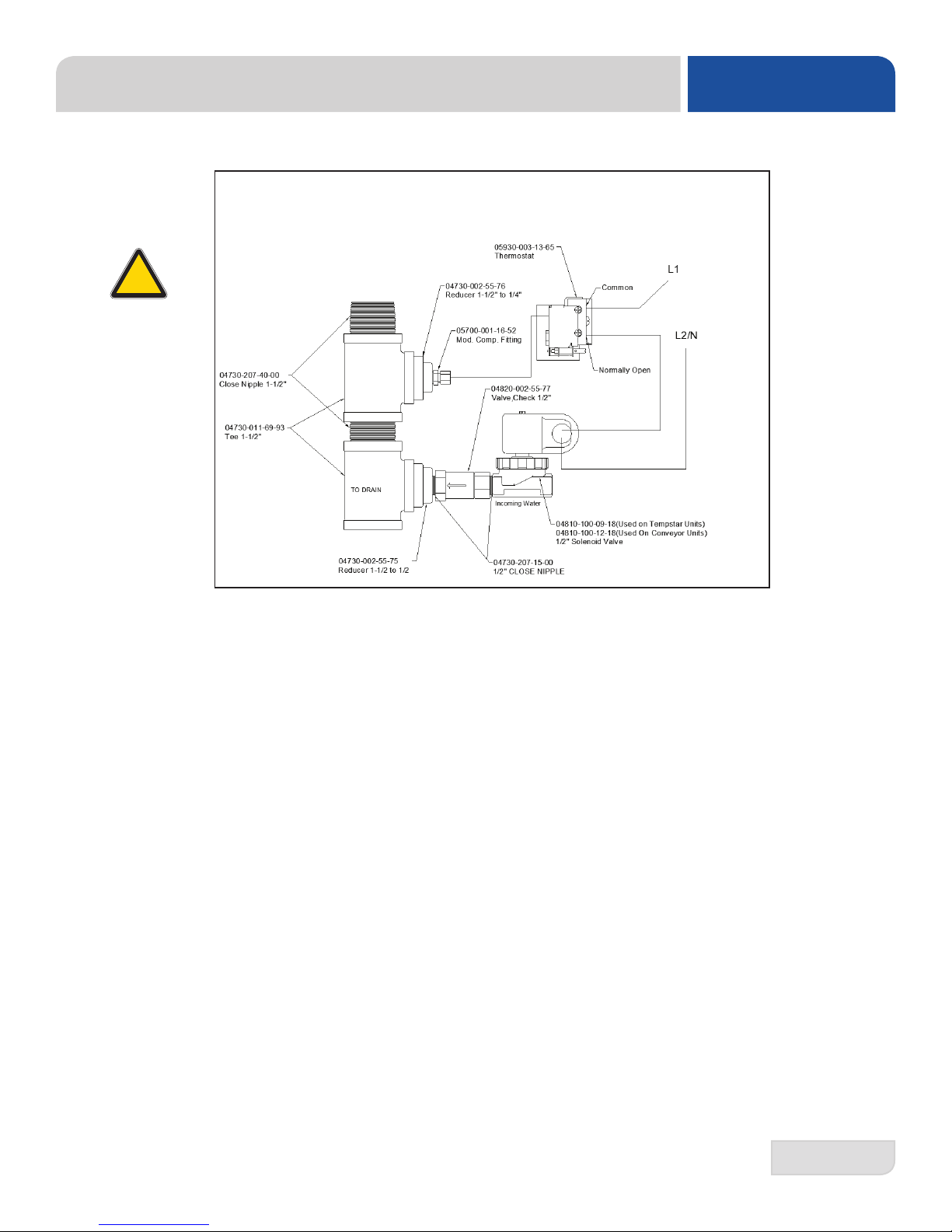
Plumbing Assembly, Main Water Inlet ...................................................................................... 36
Wash Tank Fill Assembly ......................................................................................................... 37
Pre-Wash Tank Fill Assemblies ................................................................................................ 38
Wash Manifold & Arm Assembly ...............................................................................................39
Pre-Wash Manifold & Arm Assemblies ......................................................................................41
Rinse Assembly ........................................................................................................................43
Pawl Bar Assemblies ................................................................................................................45
Pawl Bar Bracket Assembly ......................................................................................................46
Pawl Bar Gutter Assembly ........................................................................................................47
Rack Paddle Assembly .............................................................................................................48
Page 9

TABLE OF CONTENTS
PARTS
Rinse Paddle Assemblies .........................................................................................................49
Drain Assembly Parts ...............................................................................................................50
Covers, Guards & Panels ..........................................................................................................51
Brackets ....................................................................................................................................52
Miscellaneous Parts ..................................................................................................................53
Ventilation Cowl Parts ...............................................................................................................54
Ventilation Cowl for Unhooded Side-Loader .............................................................................55
Drive Assembly .........................................................................................................................56
Side-Loaders ............................................................................................................................58
Side-Loader Drive Linkage .......................................................................................................60
Steam Heating Coil Assembly ..................................................................................................62
Booster Heater Option (Electric) ...............................................................................................63
Booster Heater Option (Steam) .................................................................................................64
Blower/Dryer Option, Machine Assembly ..............................................................................66
Blower/Dryer Option, Control Box .........................................................................................67
Blower/Dryer Option, Blower Assembly ................................................................................68
SCHEMATICS
Booster Heater, 3-Phase ...........................................................................................................69
Booster Heater, 1-Phase, 12kW ................................................................................................70
Booster Heater, 1-Phase, 18kW ...............................................................................................71
Steam Booster Heater ..............................................................................................................72
Temperature Board ...................................................................................................................73
Photocell Table Limit Switch ......................................................................................................74
44" 208/230/460V, 60Hz, 3-Phase ............................................................................................75
44" 208/230V, 60Hz, 1-Phase ...................................................................................................76
44" Steam, 208/230/460V, 60Hz, 3-Phase ................................................................................77
44" Steam, 208/230V, 60Hz, 1-Phase .......................................................................................78
66" 208/230/460V, 60Hz, 3-Phase ............................................................................................79
66" 208/230V, 60Hz, 1-Phase ...................................................................................................80
66" Steam, 208/230/460V, 60Hz, 3-Phase ...............................................................................81
66" Steam, 208/230V, 60Hz, 1-Phase ......................................................................................82
Blower/Dryer, 240V ...................................................................................................................83
Blower/Dryer, 480V ...................................................................................................................84
Page 10
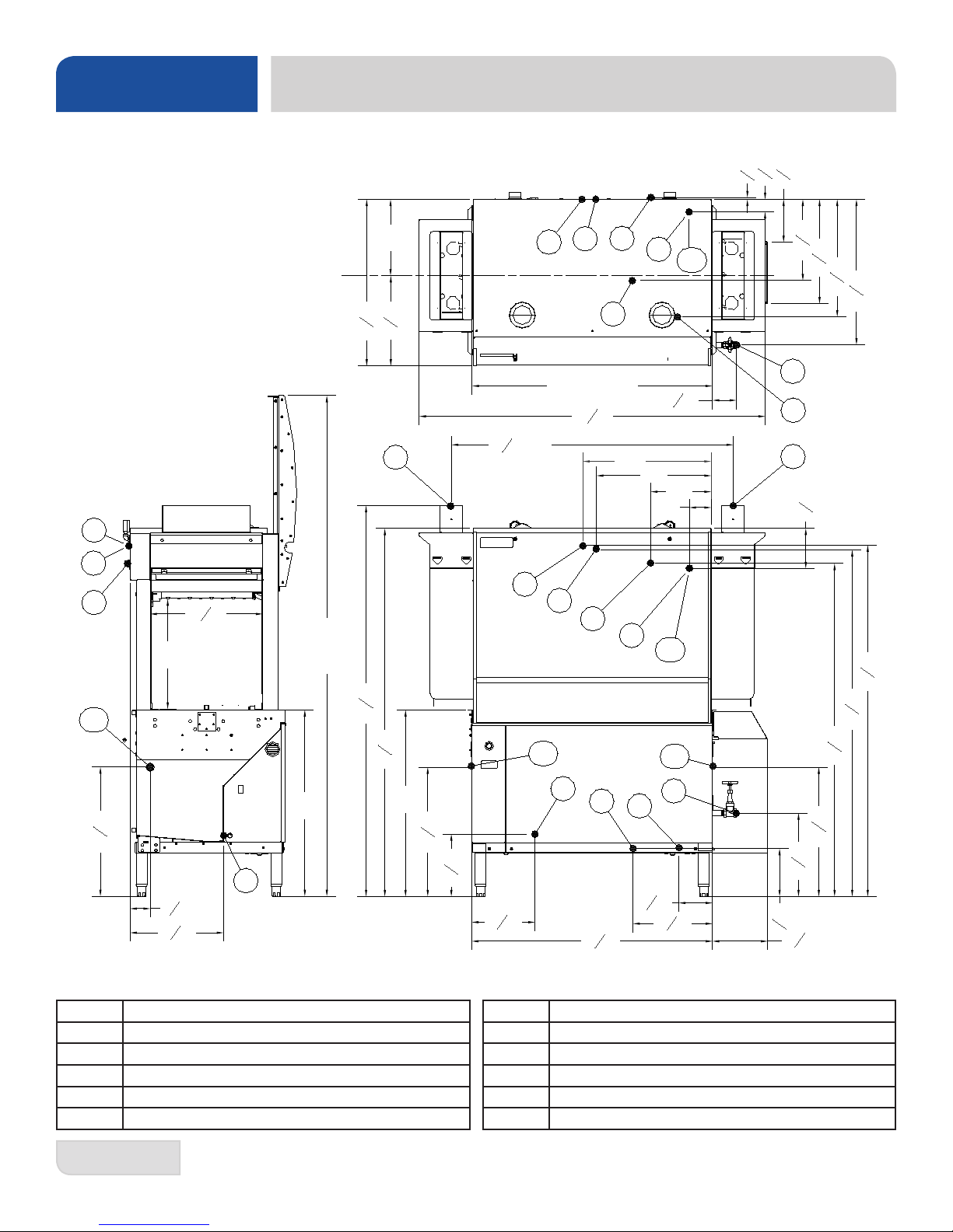
SPECIFICATIONS
44" LEFT-TO-RIGHT
NOTE 1:
THE MAXIMUM DOOR HEIGHT MAY BE
REDUCED BY THE ADDITION OF OPTIONAL
DOOR BRACKETS. MAXIMUM HEIGHTS OF
91", 89" & 87" ARE AVAILABLE.
NOTE 2:
VENTILATION DUCT ADAPTERS ARE
ADJUSTABLE FROM 51-1/2" TO 54".
NOTE 3:
THE DRIVE ASSEMBLY AND GUARD
MAY BE INSTALLED ON EITHER END
OF THE UNIT. INSTALLATION ON THE
UNLOAD END IS STANDARD. IF
INSTALLED ON THE LOAD END,
PLEASE ENSURE ANY SCRAP SINKS
IN THE TABLING ARE AT AN ADEQUATE
DISTANCE TO PROVIDE FOR CLEARANCE
OF THE DRIVE ASSEMBLY.
NOTE 4:
NOTE 4:
ALL DIMENSIONS FROM THE
ALL VERTICAL DIMENSIONS MAY
VARY DUE TO THE ADJUSTABLE
FLOOR CAN BE INCREASED
FEET.
1 3/4" USING THE MACHINE'S
ADJUSTABLE FEET.
E1
44" MACHINE DIMENSIONS
in
in
in
4
8
8
1
7
3
2
7
in
S*
C*
V2
8
7
in
8
14
1
in
19
2
1
in
8
21
5
26
in
8
3
7
14 in
E1
RA
SAN
W
E2
in
in
2
2
1
1
30
16
TABLE to TABLE
1
51
in MIN
V1
2
(NOTE 2)
63
44 in
3
D
3
4
in
in
8
23.50
8
21 in
11 in
4 in
E2
W
DET
in
4
3
23
(NOTE 4)
17
5
in
20
8
20 in
CP
3
3
in
4
1
in
8
(NOTE 4)
(NOTE 1)
93 in MAX
in
8
5
71
in
2
1
67
34 in
34 in
(NOTE 4)
*Applies to steam heated units
** Chemical sanitizing units only
E1 MAIN ELECTRICAL CONNECTION (1.375” DIA HOLE)
E2 BOOSTER HEATER ELECT. CONNECTION (1.375" DIA)
W MAIN INLET WATER CONNECTION (1/2 NPT-F)
D DRAIN CONNECTION (1-1/2" NPT-F)
DET DETERGENT BULKHEAD ACCESS (.875" DIA HOLE)
SAN** SANITIZER INLET TO RINSE (1/8" NPT-F)
E1
E2
W
RA
SAN
DET
CP
D
in
4
3
23
in
2
1
11
1
11
in
2
44
1
in
8
C*
DET
S*
in
3
23
in
4
1
15
1
in
6
8
1
14
in
2
in
4
3
8
1
10
8
(NOTE 4)
in (NOTE 3)
in
2
1
64
in
8
5
63
in
8
1
61
4
RA RINSE AID CONNECTION TO RINSE (1/8" NPT-F)
CP CONDUCTIVITY PROBE ACCESS (.875" DIA HOLE)
S* STEAM TO WASH TUB HEATING COIL (3/4" NPT-F)
C* CONDENSATE RETURN (3/4" NPT-F)
VI VENTILATION DUCT CONN. (LOAD END) 4" x 16" ID
V2 VENTILATION DUCT CONN. (UNLOAD END) 4" x 16" ID
1
07610-003-78-18-N
Page 11
44" MACHINE DIMENSIONS
in
in
8
in
4
7
in
8
7
in
8
14
1
19
8
1
7
2
3
W
E2
44 in
63
E1
4 in
D
3
4
in
8
3
in
8
5
51
in
8
(NOTE 2)
RA
SAN
TABLE to TABLE
5
23
in
V2
in
8
3
7
11
1
in
8
1
4
21
8
1
in
8
in
4
SPECIFICATIONS
44" RIGHT-TO-LEFT
NOTE 1:
THE MAXIMUM DOOR HEIGHT MAY BE
REDUCED BY THE ADDITION OF OPTIONAL
DOOR BRACKETS. MAXIMUM HEIGHTS OF
in
2
1
14 in
21
in
8
V1
C*
5
26
S*
16 in
in
in
2
2
1
1
30
16
91", 89" & 87" ARE AVAILABLE.
NOTE 2:
VENTILATION DUCT ADAPTERS ARE
ADJUSTABLE FROM 51-1/2" TO 54".
NOTE 3:
THE DRIVE ASSEMBLY AND GUARD
MAY BE INSTALLED ON EITHER END
OF THE UNIT. INSTALLATION ON THE
UNLOAD END IS STANDARD. IF
INSTALLED ON THE LOAD END,
PLEASE ENSURE ANY SCRAP SINKS
IN THE TABLING ARE AT AN ADEQUATE
DISTANCE TO PROVIDE FOR CLEARANCE
OF THE DRIVE ASSEMBLY.
NOTE 4:
NOTE 4:
ALL VERTICAL DIMENSIONS MAY
ALL DIMENSIONS FROM THE FLOOR CAN BE
VARY DUE TO THE ADJUSTABLE
INCREASED 1 3/4" USING THE MACHINE'S
FEET.
ADJUSTABLE FEET.
E1
E1
E2
W
RA
11
SAN
1
2
CP
in
44
1
C*
D
1
6
in
8
in
4
3
in
8
14
8
in
2
1
64
in
8
5
63
(NOTE 4)
(NOTE 3) 10
in
8
1
61
DET
in
4
3
23
in
2
1
11
1
in
8
*Applies to steam heated units
** Chemical sanitizing units only
E1 MAIN ELECTRICAL CONNECTION (1.375” DIA HOLE)
E2 BOOSTER HEATER ELECT. CONNECTION (1.375" DIA)
W MAIN INLET WATER CONNECTION (1/2 NPT-F)
D DRAIN CONNECTION (1-1/2" NPT-F)
DET DETERGENT BULKHEAD ACCESS (.875" DIA HOLE)
SAN** SANITIZER INLET TO RINSE (1/8" NPT-F)
DET
S*
1
2
E2
W
5
20
in
in
8
5
71
in
2
1
67
in
4
3
23
in
4
1
15
9 in
(NOTE 4)
in
3
4
in
8
(NOTE 1)
93 in MAX
34 in
(NOTE 4)
8
20 in
DET
in
4
3
23
CP
S*
3
3
17
in
4
1
in
8
(NOTE 4)
RA RINSE AID CONNECTION TO RINSE (1/8" NPT-F)
CP CONDUCTIVITY PROBE ACCESS (.875" DIA HOLE)
S* STEAM TO WASH TUB HEATING COIL (3/4" NPT-F)
C* CONDENSATE RETURN (3/4" NPT-F)
VI VENTILATION DUCT CONN. (LOAD END) 4" x 16" ID
V2 VENTILATION DUCT CONN. (UNLOAD END) 4" x 16" ID
07610-003-78-18-N
2
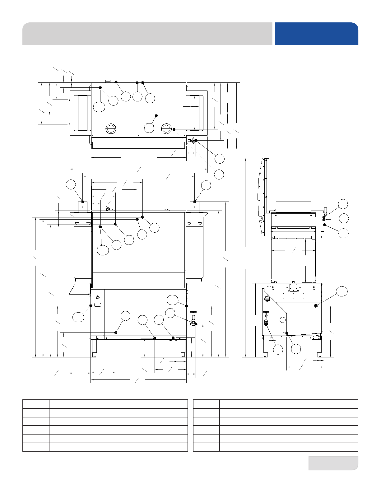
Page 12
SPECIFICATIONS
66" LEFT-TO-RIGHT
NOTE 1:
THE MAXIMUM DOOR HEIGHT MAY BE
REDUCED BY THE ADDITION OF OPTIONAL
DOOR BRACKETS. MAXIMUM HEIGHTS OF
91", 89" & 87" ARE AVAILABLE.
NOTE 2:
VENTILATION DUCT ADAPTERS ARE
ADJUSTABLE FROM 73-1/2" TO 76".
NOTE 3:
THE DRIVE ASSEMBLY AND GUARD
MAY BE INSTALLED ON EITHER END
OF THE UNIT. INSTALLATION ON THE
UNLOAD END IS STANDARD. IF
INSTALLED ON THE LOAD END,
PLEASE ENSURE ANY SCRAP SINKS
IN THE TABLING ARE AT AN ADEQUATE
DISTANCE TO PROVIDE FOR CLEARANCE
OF THE DRIVE ASSEMBLY.
NOTE 4:
NOTE 4:
ALL VERTICAL DIMENSIONS MAY
ALL DIMENSIONS FROM THE
VARY DUE TO THE ADJUSTABLE
FLOOR CAN BE INCREASED
FEET.
1 3/4" USING THE MACHINE'S
ADJUSTABLE FEET.
E1
E2
W1
20 in
5
20
in
8
DET
in
4
3
23
CP
33 in
1
17
in
8
(NOTE 4)
14 in
in
in
8
8
5
5
30
16
V1
(NOTE 1)
93 in MAX
in
2
1
63
61 in
34 in
(NOTE 4)
*Applies to steam heated units
** Chemical sanitizing units only
*** Pre-wash cold water thermostat option only
E1 MAIN ELECTRICAL CONNECTION (1.375” DIA HOLE)
E2 BOOSTER HEATER ELECT. CONNECTION (1.375" DIA)
W1 MAIN INLET WATER CONNECTION (1/2 NPT-F)
W2 PRE-WASH INLET WATER CONN. (1/2 NPT-F)
W3*** PRE-WASH COLD WATER CONN. (1/2 NPT-F)
D1 DRAIN CONNECTION, WASH (1-1/2" NPT-F)
D2 DRAIN CONNECTION, PRE-WASH (1-1/2" NPT-F)
DET DETERGENT BULKHEAD ACCESS (.875" DIA HOLE)
in
8
7
14
16 in
4 in
7
10
in
8
in
2
1
11
in
4
3
8
W3***
W3***
5
7
8
66" MACHINE DIMENSIONS
in
in
4
8
9 in
1
3
2
W1
E2
66
66 in
E1
CP
1
8
E1
D1
E2
W1
D1
in
D2
1
73
2
(NOTE 2)
W2
in
1
33
in
2
W2
TABLE to TABLE
1
85
in
2
in MIN
D2
SAN** SANITIZER INLET TO RINSE (1/8" NPT-F)
RA RINSE AID CONNECTION TO RINSE (1/8" NPT-F)
CP CONDUCTIVITY PROBE ACCESS (.875" DIA HOLE)
S* STEAM TO WASH TUB HEATING COIL (3/4" NPT-F)
C* CONDENSATE RETURN (3/4" NPT-F)
VI VENTILATION DUCT CONN. (LOAD END) 4" x 16" ID
V2 VENTILATION DUCT CONN. (UNLOAD END) 4" x 16" ID
RA
SAN**
S*
C*
1
23
in
RA
C*
2
21 in
1
6
11
1
in
4
4
SAN**
DET
S*
in
8
1
14
1
in
8
in
2
V2
in
8
3
7
in
1
15
9 in
1
10
(NOTE 4)
8
in
4
3
8
in
8
7
in
8
14
3
in
20
1
21
in
1
64
in
8
5
63
in
8
1
61
4
in (NOTE 3)
2
in
8
5
26
in
8
5
71
in
2
1
67
2
3
07610-003-78-18-N
Page 13
66" MACHINE DIMENSIONS
in
in
3
7
in
8
7
in
8
in
14
1
2
1
in
19
8
21
5
26
S*
C*
V2
in
4
8
4
1
3
2
E1
E2
W1
RA
SAN**
D1
85
1
in
8
in
4
TABLE to TABLE
66 in
1
in
2
3
in
4
8
1
in
23
2
21 in
11
1
4
D2
1
73
(NOTE 2)
7
10
W2
8
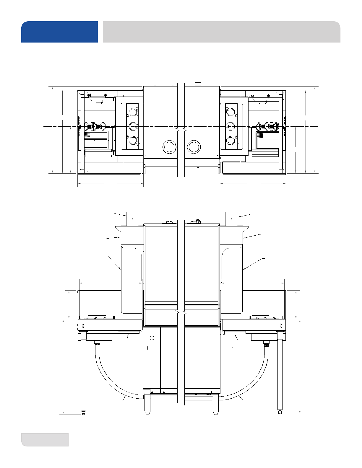
SPECIFICATIONS
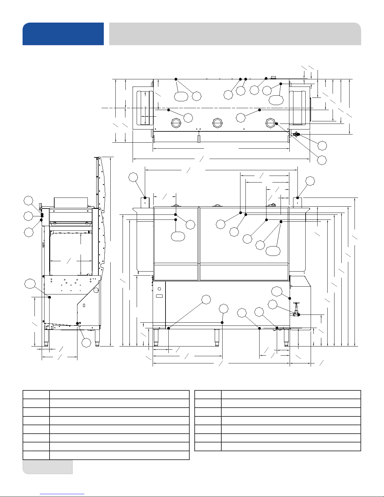
66" RIGHT-TO-LEFT
NOTE 1:
THE MAXIMUM DOOR HEIGHT MAY BE
W3***
4 in
in
2
in
14 in
16 in
in
in
8
8
5
5
30
16
V1
REDUCED BY THE ADDITION OF OPTIONAL
DOOR BRACKETS. MAXIMUM HEIGHTS OF
91", 89" & 87" ARE AVAILABLE.
NOTE 2:
VENTILATION DUCT ADAPTERS ARE
ADJUSTABLE FROM 73-1/2" TO 76".
NOTE 3:
THE DRIVE ASSEMBLY AND GUARD
MAY BE INSTALLED ON EITHER END
OF THE UNIT. INSTALLATION ON THE
UNLOAD END IS STANDARD. IF
INSTALLED ON THE LOAD END,
PLEASE ENSURE ANY SCRAP SINKS
IN THE TABLING ARE AT AN ADEQUATE
DISTANCE TO PROVIDE FOR CLEARANCE
OF THE DRIVE ASSEMBLY.
NOTE 4:
NOTE 4:
ALL DIMENSIONS FROM THE FLOOR
ALL VERTICAL DIMENSIONS MAY
VARY DUE TO THE ADJUSTABLE
CAN BE INCREASED 1 3/4" USING THE
FEET.
MACHINE'S ADJUSTABLE FEET.
E1
E2
66
E2
D1
E1
D2
1
in
8
in
8
5
71
in
2
1
67
in
1
64
(NOTE 4)
in
8
3
7
SAN**
2
in
8
5
63
in
8
1
61
in
4
1
15
1
6
in
8
in
2
1
9 in
11
10
DET
1
W1
RA
S*
C*
5
11
8
in (NOTE 3)
8
1
29
2
CP
in
in
*Applies to steam heated units
** Chemical sanitizing units only
*** Pre-wash cold water thermostat option only
E1 MAIN ELECTRICAL CONNECTION (1.375” DIA HOLE)
E2 BOOSTER HEATER ELECT. CONNECTION (1.375" DIA)
W1 MAIN INLET WATER CONNECTION (1/2 NPT-F)
W2 PRE-WASH INLET WATER CONN. (1/2 NPT-F)
W3*** PRE-WASH COLD WATER CONN. (1/2 NPT-F)
D1 DRAIN CONNECTION, WASH (1-1/2" NPT-F)
D2 DRAIN CONNECTION, PRE-WASH (1-1/2" NPT-F)
DET DETERGENT BULKHEAD ACCESS (.875" DIA HOLE)
W2
W3***
(NOTE 1)
93 in MAX
in
2
1
63
61 in
34 in
in
4
3
8
3
3
17
in
4
1
in
8
5
7
in
8
(NOTE 4) (NOTE 4)
CP
SAN** SANITIZER INLET TO RINSE (1/8" NPT-F)
RA RINSE AID CONNECTION TO RINSE (1/8" NPT-F)
CP CONDUCTIVITY PROBE ACCESS (.875" DIA HOLE)
S* STEAM TO WASH TUB HEATING COIL (3/4" NPT-F)
C* CONDENSATE RETURN (3/4" NPT-F)
VI VENTILATION DUCT CONN. (LOAD END) 4" x 16" ID
V2 VENTILATION DUCT CONN. (UNLOAD END) 4" x 16" ID
W1
DET
in
3
23
4
(NOTE 4)
07610-003-78-18-N
4
Page 14
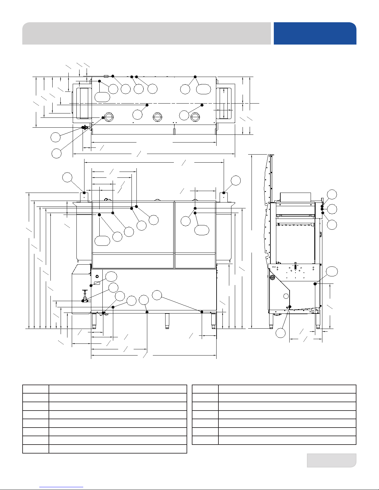
SPECIFICATIONS
SIDE-LOADER DIMENSIONS
23" L-R UNHOODED
30.32
29.00
16.35
DIMENSION IS 30.00" FOR THE
30" UNHOODED SIDE-LOADER
ADJUSTABLE VENTILATION
DUCT ADAPTER
VENTILATION SCOOP
SIDE-LOADER
23.00
23" R-L UNHOODED
SIDE-LOADER
DIMENSION IS 30.00" FOR THE
30" UNHOODED SIDE-LOADER
23.00
ADJUSTABLE VENTILATION
DUCT ADAPTER
VENTILATION SCOOP
30.32
29.00
16.35
VENTILATION COWL
WITH CUTOUT FOR
L-R UNITS
10.00
+1.00
34.00
-1.00
22.00
ELECTRICAL
CONDUIT
SIDE-LOADER
DRAIN HOSE
ELECTRICAL
CONDUIT
SIDE-LOADER
DRAIN HOSE
22.00
VENTILATION COWL
WITH CUTOUT FOR
R-L UNITS
10.00
34.00
+1.00
-1.00
5
07610-003-78-18-N
Page 15
STEAM BOOSTER HEATER DIMENSIONS
33.69
1
20
in
4
W1
S
SPECIFICATIONS
24 in
E
W2
PS
PW
in
2
1
17
in
8
3
11
E
PW
28
PS
5
22 in
in
8
20
W2
S
PW
W2
in
8
1
E
33
in
4
3
20
in
8
5
in
14
8
7
2
3
3
in
8
3
19
in
8
1
in
8
C
C
1
PS
10
3
1
8
in
4
1
7
5
22 in
in
8
S
W1
in
8
1
11
in
2
in
7
8
in8
8
E MAIN ELECTRICAL CONNECTION (7/8" DIA HOLE)
W1 MAIN INLET WATER CONNECTION (3/4" NPT-F)
W2 WATER OUTLET CONNECTION (3/4" NPT-F)
PW WATER PRESSURE RELIEF OUTLET (3/4" NPT-F)
07610-003-78-18-N
PS STEAM PRESSURE RELIEF OUTLET (1" NPT-F)
S STEAM SUPPLY TO BOOSTER (1" NPT-F)
C STEAM CONDENSATE CONNECTION (3/4" NPT-F)
6
Page 16
102.07
SPECIFICATIONS
WITH 44" DISHMACHINE
BLOWER/DRYER OPTION DIMENSIONS
48.07
25.50
ELECTRICAL
CONNECTION
9.00
102.07
WITH 66" DISHMACHINE
7
124.06
9.00
48.07
ELECTRICAL
CONNECTION
25.50
Machine Dimensions:
Height 72.5"
Width 48"
Depth 30.625"
Wall Clearance: 5'
Height 19.75"
Width 21"
Shipping Weight: 750lbs.
Shipping Size:
Length 77"
Depth 41"
Height 89"
07610-003-78-18-N
Page 17

OPERATING PARAMETERS
NOTICE
Model Designation: 44" 66" 44" STEAM 66" STEAM
Operating Capacity:
Racks per Hour 218 218 218 218
Dishes per Hour 3488 3488 3488 3488
Glasses per Hour 7848 7848 7848 7848
Tank Capacity (Gallons):
Wash Tank 35.6 35.6 35.6 35.6
Pre-Wash Tank N/A 15.8 N/A 15.8
Electrical Loads (as applicable):
Wash Motor HP 3.0 3.0 3.0 3.0
SPECIFICATIONS
Drive Motor HP 0.25 0.25 0.25 0.25
Pre-Wash Motor HP N/A 2.0 N/A 2.0
Wash Heater kW 15 or 18 18 N/A N/A
NOTE: Always refer to the machine data plate for specic electrical and water requirements.
The material provided on this page is for reference only and may change without notice.
i
07610-003-78-18-N
8
Page 18

SPECIFICATIONS
NOTICE
Model Designation: 44" 66" 44" STEAM 66" STEAM
HOT WATER SANITIZING
Water Temperatures (°F):
Pre-Wash Temperature (recommended) N/A 110-140 N/A 110-140
Minimum Wash Temperature 160 160 160 160
Incoming Rinse Temperature 180 180 180 180
Incoming Water Temperature
12 kW Booster 140 140 N/A N/A
18 kW Booster 110 110 N/A N/A
No Booster 180 180 180 180
CHEMICAL SANITIZING
Water Temperatures (°F):
OPERATING PARAMETERS
Pre-Wash Temperature (recommended) N/A 110-140 N/A 110-140
Minimum Wash Temperature 120 120 120 120
Minimum Rinse Temperature 120 120 120 120
Incoming Water Temperature
12 kW Booster 80 80 N/A N/A
18 kW Booster 50 50 N/A N/A
No Booster 120 120 120 120
Other Water Requirements:
Water Flow Pressure (PSI) 15 15 15 15
Flow Rate Minimum (GPM) 1.27 1.18 1.27 1.18
Water Line Size (NPT) 1/2" 1/2" 1/2" 1/2"
Drain Line Size (NPT) 1-1/2" 1-1/2" 1-1/2" 1-1/2"
Steam Requirements:
Steam Line for Wash Tank (NPT) N/A N/A 3/4" 3/4"
Steam Flow Pressure (PSI) N/A N/A 10-20 10-20
Consumption @ 15 PSI (lbs/hr) N/A N/A 60 60
NOTE: Always refer to the machine data plate for specic electrical and water requirements.
The material provided on this page is for reference only and may change without notice.
i
9
07610-003-78-18-N
Page 19

ELECTRICAL REQUIREMENTS
SPECIFICATIONS
i
All electrical ratings provided in this manual are for reference only. Always refer to the machine data plate to get the exact
electrical information for this machine. All electrical work performed on machines should be done in accordance
with applicable local, state, territorial, and national codes. Work should only be performed by qualied electricians and
authorized service agents. A list of authorized Service Agencies is located in the back of this manual.
Note that all electrical wiring used in the dishmachine must be rated, at a minimum, for 212 °F (100 °C), and that only
copper conductors must be used.
Where applicable, heating element amperage draws have been adjusted for the assumed input voltage. The manufacturer
assumes incoming voltages will be either 208, 230, or 460 Volts. Some of the heating elements used in our machines are
actually rated for other voltages, such as 240 or 480 Volts. Always verify the amperage draw of the machine in operation
when sizing circuit protection.
If the machine is equipped with the optional rinse heater, note the rinse heater has its own electrical connection and
therefore requires a separate service. Amperage loads for motors and heaters are called out on the machine data plate
for the installation/service technician.
The electrical congurations of the machines are as follows:
Available Electrical Characteristics:
• 208 V, 60 Hz, Single-phase
• 230 V, 60 Hz, Single-phase
• 208 V, 60 Hz, Three-phase
• 230 V, 60 Hz, Three-phase
• 460 V, 60 Hz, Three-phase
Available Wash Tank Heaters:
• 15 kW (standard for CREW 44)
• 18 kW (optional for CREW 44, standard for CREW 66)
Available Electrical Characteristics:
• None (standard)
• 12 kW (40 °F rise in temperature)
• 18 kW (70 °F rise in temperature)
07610-003-78-18-N
10
Page 20
SPECIFICATIONS
44" with 15 kW Wash Heater
ELECTRICAL REQUIREMENTS
i
Wash
Volts Phase Freq
208 1 60 10.0 1.8 72.1 83.9
230 1 60 10.0 1.8 *59.9 71.7
240 1 60 10.0 1.8 62.5 74.3
208 3 60 8.6 1.1 41.6 51.3
230 3 60 8.4 1.1 *34.6 44.1
240 3 60 8.4 1.1 36.1 45.6
460 3 60 4.2 0.6 **17.3 22.1
480 3 60 4.2 0.6 18.1 22.9
44" with 18 kW Wash Heater
Volts Phase Freq
208 1 60 10.0 1.8 86.5 98.3
230 1 60 10.0 1.8 *71.9 83.7
240 1 60 10.0 1.8 75.0 86.8
208 3 60 8.6 1.1 50.0 59.7
230 3 60 8.4 1.1 *41.5 51.0
240 3 60 8.4 1.1 43.4 52.9
460 3 60 4.2 0.6 **20.8 25.6
480 3 60 4.2 0.6 21.7 26.5
* Denotes 240 volt heating elements that have been down-rated when 230 volts is applied.
** Denotes 480 volt heating elements that have been down-rated when 460 volts is applied.
Motor
Amps
Wash
Motor
Amps
Drive
Motor
Amps
Drive
Motor
Amps
Wash
Heater
Amps
Wash
Heater
Amps
Total
Load
Total
Load
44" Steam
Volts Phase Freq
208 1 60 10.0 1.8 11.8
230 1 60 10.0 1.8 11.8
208 3 60 8.6 1.1 9.7
230 3 60 8.4 1.1 9.5
460 3 60 4.2 0.6 4.8
11
Wash
Motor
Amps
Drive
Motor
Amps
Total
Load
07610-003-78-18-N
Page 21
ELECTRICAL REQUIREMENTS
i
66" with 18 kW Wash Heater
SPECIFICATIONS
Pre-Wash
Volts Phase Freq
208 1 60 10.2 10.0 1.8 86.5 108.5
230 1 60 9.4 10.0 1.8 *71.9 93.1
240 1 60 9.4 10.0 1.8 75.0 96.2
208 3 60 6.8 8.6 1.1 50.0 66.5
230 3 60 6.4 8.4 1.1 *41.5 57.47
240 3 60 6.4 8.4 1.1 43.4 59.3
460 3 60 3.2 4.2 0.6 **20.8 28.8
480 3 60 3.2 4.2 0.6 21.7 29.7
* Denotes 240 volt heating elements that have been down-rated when 230 volts is applied.
** Denotes 480 volt heating elements that have been down-rated when 460 volts is applied.
66" Steam
Volts Phase Freq
208 1 60 10.2 10.0 1.8 22.0
230 1 60 9.4 10.0 1.8 21.2
208 3 60 6.8 8.6 1.1 16.5
230 3 60 6.4 8.4 1.1 15.9
460 3 60 3.2 4.2 0.6 8.0
Motor
Amps
Pre-Wash
Motor
Amps
Wash
Motor
Amps
Wash
Motor
Amps
Drive
Motor
Amps
Wash
Heater
Amps
Drive
Motor
Amps
Total
Load
Total
Load
40 °F Rise – 12 kW Booster
Rinse
Volts Phase Freq
208 1 60 57.7
230 1 60 47.9
208 3 60 33.3
230 3 60 27.7
460 3 60 13.8
Note: On the 208 volt machines, the rinse heater is actually rated at 17.2 kW.
Blower/Dryer
Volts Phase Freq Amps
208 3 60 32.2
230 3 60 22.9
460 3 60 13.4
07610-003-78-18-N
Heater
Amps
70 °F Rise – 18 kW Booster
Volts Phase Freq
208 1 60 82.7
230 1 60 71.9
208 3 60 47.7
230 3 60 41.5
460 3 60 20.7
Rinse
Heater
Amps
12
Page 22

INSTALLATION
INSTRUCTIONS
VISUAL
INSPECTION
Do not throw away the
container if damage is
evident!
UNPACKING THE
MACHINE
LEVEL THE
DISHMACHINE
Before installing the unit, check the packaging and the machine for damage. Damaged
packaging might be an indication there is possible damage to the product. If there is
any type of damage to both the packaging and the unit, DO NOT THROW AWAY THE
PACKAGING. The dishmachine has been previously inspected at the factory and is
expected to arrive in new, undamaged condition. However, rough handling by carriers
or others might result in damage to the unit while it is in transit. If this occurs, DO NOT
RETURN THE UNIT TO THE MANUFACTURER. Instead, contact the carrier and ask them
to send a representative to the site to inspect the damage and request that an inspection
report be completed. Contact the carrier and dealer that sold you the unit within 48 hours
of receiving the machine in order to report possible freight damage.
The machine should be unboxed and removed from the pallet before installing. Remove
the wooden lift beams and their associated brackets after the unit has been positioned.
Open the front door and remove all materials from inside. Once unpacked, verify there are
no missing parts. If a part is missing, contact the manufacturer immediately.
The dishmachine is designed to operate while level. This is important to prevent any damage
to the machine during operation and to ensure the best possible results. The unit comes
equipped with adjustable bullet feet, which can be turned using a pair of pliers. Verify the
unit is level from front-to-back and side-to-side before making any electrical or plumbing
connections.
PLUMBING THE
DISHMACHINE
The plumber MUST ush
the incoming water line!
i
13
All plumbing connections must be made to adhere to local, state, territorial, and national
codes. The installing plumber is responsible for ensuring the incoming water lines are
ushed of debris before connecting to the machine. Note that chips and materials from
cutting processes can become lodged in the solenoid valves and prevent them from
opening or closing. Any valves that are found to be fouled or defective because of foreign
matter left in the water line and any subsequent water damage are not the responsibility of
the manufacturer.
Water hardness should be a maximum of 6 GPG. Hard water should be treated before
being used by the machine. Iron in the water line can cause staining. A lter designed
to remove iron from the water supply is highly recommended for supplies in excess of
0.1 ppm.
This dishmachine comes with a pressure regulator. The unit utilizes a ow pressure of 15
PSI for the incoming water line. Do not confuse static pressure with ow pressure. Static
pressure occurs when there is no ow and the valves are closed. Flow pressure occurs
when water is running into the machine. The pressure regulator should be adjusted to the
proper ow pressure indicated on the data plate.
The water supply line must be 1/2" NPT minimum and must be able to provide water at the
minimum temperature indicated on the machine data plate.
A shut-off valve should be installed to allow isolating the dishmachine from the water
system in the event service is required. It is also suggested that a shock absorber (not
supplied with dishmachine) be installed on the incoming water line. This prevents water
hammer (hydraulic shock)—induced by the solenoid valve as it operates—from causing
damage to the equipment.
07610-003-78-18-N
Page 23
INSTRUCTIONS
NOTICE
INSTALLATION
CONNECTING
THE DRAIN LINE
STEAM LINE
CONNECTIONS
i
ELECTRICAL
POWER
CONNECTIONS
Disconnect electrical
power at the breaker or
disconnect switch and
tag-out in accordance
with procedures and
codes.
The drain for the unit is a gravity discharge drain. All piping to the machine drain must be
a minimum 1-1/2” NPT AND MUST NOT BE REDUCED. There must also be an air gap
between the machine drain line and the oor sink or drain. If a grease trap is required by
code, it should have a ow capacity of 5 GPM. 44" units have one drain connection point
and 66" units have two.
Some machines covered in this manual are designed to use low-pressure steam as a
source of heat for the wash tank. Those machines come with lines by which an outside
source of steam (e.g. steam booster) is connected. Connect all steam lines from the
booster to the machine in accordance with the booster manufacturer’s instructions. Ensure
that all applicable codes and regulations are adhered to. See the machine data plate for
information related to steam ow requirements.
All electrical connections are to be made in accordance with applicable portions of local,
state, territorial, and national codes.
This manual provides reference information regarding electrical requirements and loads,
but that information may change without notice. Always refer to the machine data plate for
voltage requirements, machine voltage, total amperage load, and serial number. If a data
plate has been damaged and cannot be read, contact the manufacturer.
The main power terminal blocks (for the dishmachine and for the rinse booster heater, if
applicable) are located at the top of the machine. Remove the top cover to access these
connections. Route incoming power lines within conduit that will connect via ttings to the
pre-punched holes in the back of the control box. Install power and ground wires to lugs as
indicated by the appropriate decals in the control box. Use copper conductors only. Use of
an anti-oxidation agent is permissible on the power connections. Tighten all connections.
Verify the incoming voltage matches the voltage indicated on the decal next to the
incoming power pre-punched hole.
07610-003-78-18-N
!
CAUTION
NOTE: The dishmachine has a separate power connection from the rinse booster heater
and the circuit protection requirements are different for each. Refer to the machine data
plate for information on minimum circuit protection.
CAUTION: Improperly connecting external devices can cause damage to the machine
and/or electrical infrastructure!
SEE PAGE 17 FOR A GUIDE ON WIRING EXTERNAL DEVICES (EXHAUST FAN,
CHEMICAL DISPENSERS, ETC.)
14
Page 24

INSTALLATION
NOTICE
INSTRUCTIONS
DISHMACHINE
VENTILATION
THERMOSTATS
CHEMICAL
FEEDER
EQUIPMENT
The dishmachine should be located with an adequate exhaust hood or ventilation system
with provisions for venting. This is essential to permit efcient removal of the condensation
exhaust. Ensure the exhaust system is acceptable in accordance with applicable codes
and standards.
NOTE: Any damage that is caused by steam and/or moisture due to improper
ventilation is NOT covered under the warranty.
Dishmachine ventilation requirements:
• Load End: 200 CFM
• Unload End: 200 CFM
The exhaust system must be sized to handle this volume for the dishmachine to operate
properly.
The thermostats on this unit have been set at the factory for the wash tank and should only
be adjusted by an authorized service agent.
This dishmachine DOES NOT COME WITH AN INTEGRAL CHEMICAL
SUPPLY/FEEDER SYSTEM. For the dishmachine to operate correctly, connect it to a
third-party chemical dispenser that meets the requirements of NSF Standard 29.
Contact a chemical supplier about connecting a dispenser to the dishmachine. Chemical
dispensers must be set for the type and concentration of chemicals being used.
Detergent usage and water hardness are two factors that contribute greatly to how
efciently the dishmachine will operate. Using the proper amount of detergent can be a
source of substantial savings. A qualied water treatment specialist can explain what is
needed to gain the maximum efciency from detergent.
The dishmachine can operate in either hot-water-sanitizing mode or chemical-sanitizing
mode. The mode of the machine is marked above the machine's data plate.
If the unit is operated in chemical-sanitizing mode, ensure an appropriate chlorine-based
sanitizer is used in the nal rinse line.
15
07610-003-78-18-N
Page 25

INSTRUCTIONS
INSTALLATION
DETERGENT INJECTION POINT.
ANOTHER BULKHEAD PLUG
IS PROVIDED ON THE LEFT SIDE
OF THE UNIT
07610-003-78-18-N
BULKHEAD OPENING FOR
CONDUCTIVITY PROBE
CHEMICAL TUBE
INSERTION POINT
875"
INLET WATER FITTING
1-1/2" NPTF DRAIN CONNECTION
SHOWN FROM REAR OF LEFT TO RIGHT UNIT.
RIGHT TO LEFT UNIT IS MIRRORED
1/2" NPTF
MAIN ELECTRICAL
CONNECTION OPENING
1.375"
ADJUSTABLE BULLET FEET
BOOSTER HEATER
ELECTRICAL CONNECTION
OPENING
1.375"
16
Page 26
INSTALLATION
F
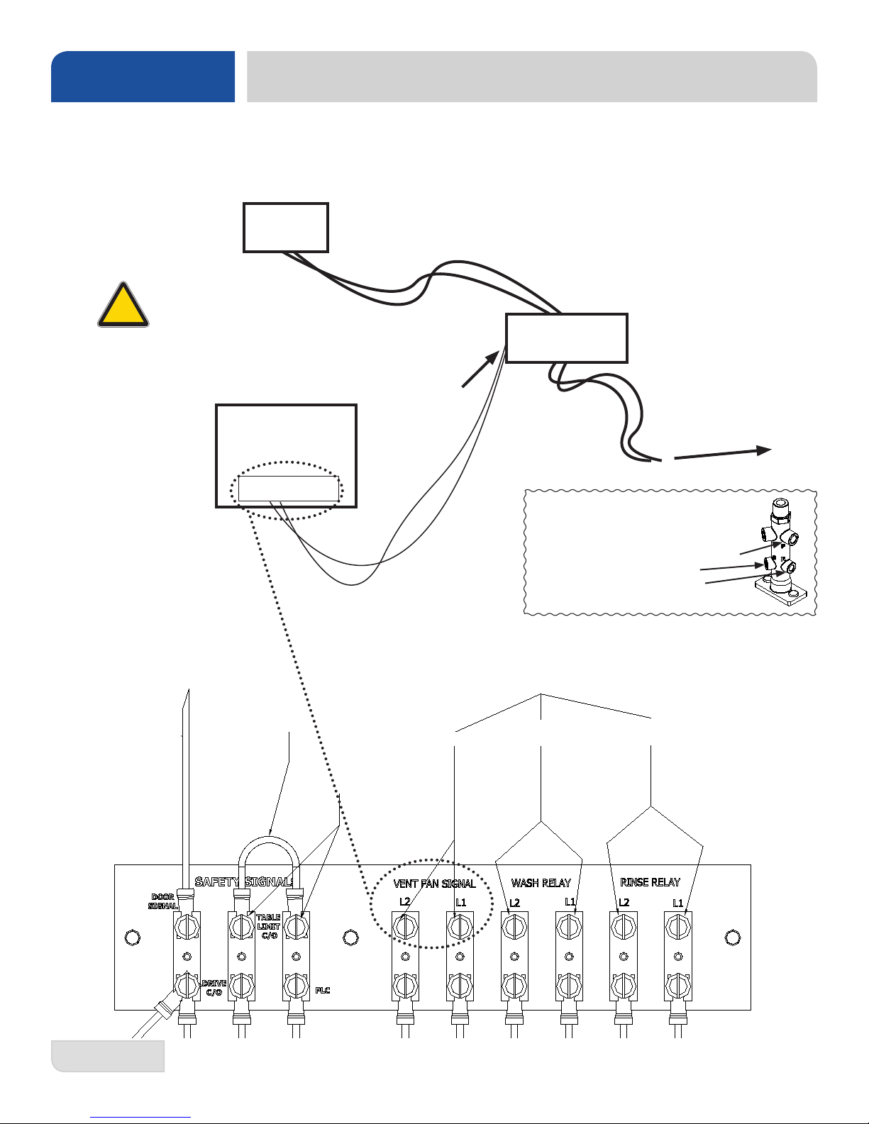
Electrical connection points for table limit switch, ventilation fan signal, and chemical dispensing systems.
!
CAUTION
Do NOT connect
primary load directly
to Terminal Board!
EXTERNAL DEVICE WIRING
Signal board is located in the main control box behind the lower dress panel.
Wiring Diagram
Vent Fan
Primary Load
Contactor
Connect
wires to coil
of contactor
or relay.
CREW
Dishmachine
Terminal Board
Supplied by Customer
To Circuit Breaker
ROM DOOR SWITCH
Terminal Board
REMOVE THIS JUMPER
WIRE TO ALLOW FOR
TABLE LIMIT SWITCH
CONNECTIONS
TABLE LIMIT
SWITCH
CONNECTION
Chemical Dispenser Tube Connection
Points to Rinse Injector:
P: Pressure Switch (1/4" NPT)
S: Sanitizer (1/8" NPT)
R: Rinse Aid (1/8" NPT)
CONNECTION POINTS FOR EXTERNAL DEVICES
115v AC Secondary Control Transformer Signal
VENT FAN
DETERGENT
DISPENSER
RINSE AID
& SANITIZER
NOTE:
Vent Fan wiring is
shown. All external
devices are wired
similarly.
17
07610-003-78-18-N
Page 27

CURTAIN INSTALLATION INSTRUCTIONS
The unit has decals marking the curtain locations inside the machine, starting at the load end and ending at the unload
end. The illustrations below indicate the size of the curtain to be placed on the curtain hooks
provided. If any curtain components are missing, these must be obtained and installed before operation.
DETERMINING CONVEYER DIRECTION: The dishmachine will be congured for either Left-to-Right or Right-to-Left
operation. Direction is from the load end to the unload end, as shown below.
INSTALLATION
44" Left-to-Right 44" Right-to-Left
XL S L L XL
Load
Unload
66" Left-to-Right
Pre-wash
XL S L S L L XL
Load
66" Right-to-Left
XL L L S L S XL
XL L L S XL
Unload
Unload
Pre-wash
Load
Unload
IMPORTANCE OF PROPER CURTAIN PLACEMENT: The curtains inside the dishmachine must be installed properly
for the machine to operate correctly. Curtains are used to control air currents inside the unit and assist in maintaining the heat
necessary to keep energy costs down. Note the approximate locations for each type of curtain in the above illustrations.
S = Short, L = Long, and XL = Extra Long. See the chart below for actual curtain lengths and part numbers. Note the
different part numbers for the curtain and curtain rod for the load end when a side-loader option is present.
Legend Length Part #
S 12" 08415-131-73-44
L 19" 08415-002-14-41
XL 24.25" 08415-002-47-37
Curtain Rod 20.50" 05700-003-77-52
07610-003-78-18-N
Side-Loader
Option
XL
(Load End Only)
Curtain Rod
(Load End Only)
Load
Part #
08415-003-84-88
05700-003-84-57
18
Page 28
INSTALLATION
• This kit should only be installed by qualified service personnel to reduce the risk of electric shock, serious injury, or
fire. A plumbing permit and the services of a licensed plumber and electrician might be required in some areas.
• Turn off the power supply and place the dishwasher disconnect (if applicable) in the off position. Lockout/tag-out to
prevent the power supply from being turned back on accidentally.
• Failure to install this kit within the guidelines might adversely affect safety, performance, component life, and warranty
coverage.
• Do NOT pull power for the Drain Quench Assembly from the machine! 120V facility power only!
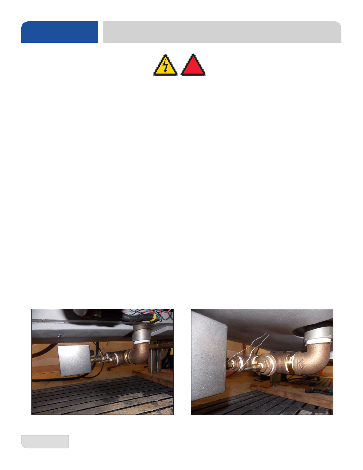
DRAIN QUENCH KIT INSTRUCTIONS
!
WARNING
Tools Required
• Pipe Wrench
• Adjustable Wrench
• 5/16” Nut Driver
• 3/8” Nut Driver or Wrench
• Phillips Screwdriver
• Pipe Thread Sealant Tape or "Pipe Dope"
• Needle-nose Pliers
Instructions
1. Connect Drain Quench Assembly to the machine drain via 1.5” NPT street elbow (04730-206-32-00).
2. Orient assembly as shown below:
19
07610-003-78-18-N
Page 29
DRAIN QUENCH KIT INSTRUCTIONS
DRAIN QUENCH SYSTEM
3. Connect user-supplied 115V cord (from facility power) into solenoid box as shown below:
!
CAUTION
Power cannot
be taken from
the machine!
INSTALLATION
4. Connect cold water to inlet side of solenoid valve.
5. Secure all electrical (ensure connection is to 120V facility power) and plumbing connections.
6. Restore water and power to the machine and verify drain quench performance.
IF THERE ARE ANY ISSUES AFTER INSTALLATION, PLEASE CONTACT
TECHNICAL SERVICE AT 1-888-800-5672.
07610-003-78-18-N
20
Page 30

OPERATION
INSTRUCTIONS
PREPARATION
POWER UP
i
Before operating the unit, verify the following:
• The drain stopper is installed.
• The strainers are installed.
• The pawl bar is installed and secure.
• The actuator switches move with relative freedom and do not bind.
• The curtains are installed correctly.
To place the unit in standby, press the START button on the front of the machine.
• The unit will automatically determine if there is proper water level in the wash tank. If
not, the unit will begin to ll until the appropriate level is reached.
• If the wash tank temperature is not at the minimum level for the mode of operation, the
wash heater will energize. Refer to the machine data plate for a better understanding of
the minimum temperatures needed to operate the unit correctly. It might take several
minutes for the wash tank to heat up, depending on the initial temperature of the water.
• If the machine is equipped with a rinse booster option, the booster will turn on when
the unit turns on.
• If the machine is heated with a steam booster, the steam booster must be turned on in
accordance with the manufacturer's instructions.
• Do not attempt to start the unit until:
1. The unit stops lling.
2. The unit has reached the appropriate wash tank temperature.
FIRST RACK
WARE
PREPARATION
WASHING A
RACK OF WARE
The rst rack of ware that is placed in the unit will typically reduce the temperature of
the wash tank, and the rst rack might need to run through the unit again. This process
may be necessary any time the unit has not been operated for an extended period of
time, although this is dependent on the type of ware being used, its temperature, and the
ambient temperature of the kitchen area. To ensure proper operation, always observe the
temperatures of the wash and rinse when rst starting the unit.
Proper preparation of ware is essential for the smooth, efcient operation of this dishma-
chine.
Any ware placed in the unit should have all solid food waste and scraps removed. Ware
should also be sprayed-down before entering the dishmachine.
Place cups and glasses upside-down in racks so they do not hold water during the cycle.
Presoak atware in warm water to assist in removing food. Load plates and saucers in the
same direction, with the food surface facing the unload end of the machine.
This dishmachine is designed to wash ware that is placed in a rack. Materials should not
be placed in the unit unless they are properly secured in a dish rack.
To start the cycle, gently push the rack into the unit on the load end. Once the wash
actuator has moved sufciently, the unit will automatically begin to convey the dish rack
through the unit. The entire cycle is automatic.
21
07610-003-78-18-N
Page 31

INSTRUCTIONS
OPERATION
OPERATIONAL
INSPECTION
i
SHUTDOWN
CLEANING
Operators should periodically review the following items while the
machine is operating. These items are important for operating the machine in an
efcient manner.
• Review wash and rinse temperatures and compare to the minimums on the data plate.
• Verify the pan strainers are not becoming clogged. Keeping these free of soil and
debris allows for much better ow of water through the machine and prevents any sort
of redeposit issues.
• Water pressure: The dishmachine is designed to run at a minimum of 15 PSI; if it
is any lower there will not be enough rinse water to properly remove detergent from the
ware.
• Wash and rinse arm nozzles should be free of debris. Open nozzles are essential to
the operation of the dishmachine.
To shut the unit down, press the START button on the front of the machine. To drain the
machine, move the drain valve to the drain position. If the machine is equipped with a
steam booster, shut it down in accordance with its manufacturer’s instructions.
Clean the unit at least once every 24 hours or at the end of the day. Cleaning assists in
maintaining the efcient operation of the unit by removing soil and debris that might otherwise become trapped in nozzles or deposited onto ware.
Do NOT clean the unit
with any type of metallic
scrubbing sponge!
• Curtains should be removed and scrubbed with mild detergent and a brush and
allowed to air-dry.
• Strainers should be removed and debris scooped out. Do not hit strainers to remove
debris; this can cause them to warp and not seat correctly. Rinsing the strainer under
water should remove the rest of any debris trapped in the part.
• Wash arms can be removed using a 7/16" driver, however the dishmachine is
designed so that the wash arms are self-cleaning. Operators have the ability to ush the
arms by removing the plastic end-caps and running a rack through the unit. This should
only be done as a cleaning function with an empty rack and a tub that is lled with water.
• The internal chamber can be cleaned with a mild detergent and dishrag. The strainers
and pawl bar should be removed to provide as much room as possible.
• The outside of the unit should be cleaned with a standard countertop or general
cleaner. Do not attempt to clean inside any compartments, boxes, or chambers that are
secured with a cover. These normally contain live electrical components.
07610-003-78-18-N
22
Page 32

OPERATION
To proceed with the delime operation, ll the dishmachine with the amount of delime solution recommended by the chemical
supplier. The tank capacities of the machine can be found in the Specications section of this manual.
After the chemicals are added, perform the following steps:
1. Flip the NORMAL/DELIME switch to DELIME.
2. Disconnect or turn off chemical feeder pumps.
3. Close all doors.
4. Press the START button and run the machine for the length of time required by the chemical supplier.
5. Press the START button to shut the unit off.
6. Open the door and step away for 5 minutes.
7. Inspect the inside of the unit to determine if expectations have been met. If not, try running the delime
solution through the unit for more time.
8. Once clean, drain the machine completely.
9. Close the door.
DELIME INSTRUCTIONS
10. Rell the unit.
11. Press the START button and run the unit in Manual for 10 minutes.
12. Press the START button to turn off the unit.
13. Open the front door.
14. Drain the unit.
15. Flip the NORMAL/DELIME switch to NORMAL.
16. The machine is ready to use.
This equipment is not recommended for use with deionized water or other aggressive uids. Use of deionized
water or other aggressive uids will result in corrosion and failure of materials and components. Use of
deionized water or other aggressive uids will void the manufacturer’s warranty.
23
07610-003-78-18-N
Page 33

TROUBLESHOOTING
MAINTENANCE
PLC TROUBLESHOOTING: Green LED lights are
illuminated on the PLC when in operation. The POWER,
OK, and RUN lights indicate that 24VDC power is available
to the PLC and that it is functioning properly. If the RUN
light is out, rst check that the RUN toggle switch located
behind the snap cover panel of the PLC is in the RUN
position.
If the switch is in the RUN position, it is possible that the
operational program of the PLC is corrupted or lost.
Temporary power surges might have occurred. Secure
all power to the machine, wait for 30 seconds, and re-
store power. Verify that the green light is illuminated to the
UTILIZE THESE SCREWS
FOR PLC REPLACEMENT
24VDC power supply immediately to the left of the PLC.
If the RUN light is still off, replace the PLC.
Refer to the illustration below for the designation of each
LED. PLC1 is used for the 44” Electric and Steam units.
An expansion PLC (PLC2) is used in conjunction with
PLC1 for 66” Electric and Steam units. Inputs correspond
to the connections behind the top ip-up panel of the PLC
and are marked I1 through I8. Outputs correspond to the
connections behind the bottom ip-up panel of the PLC and
are marked Q1 through Q8.
NOTE: All outputs are
fused. Q1 and Q2 outputs
for both PLCs utilize 1.0 A
fuses and Q3-Q8 outputs
utilize 0.75 A fuses. When
illuminated, the LED
lights on the front of each
PLC will show the input
from, and the outputs to,
INPUTS
STATUS
INDICATING
LIGHTS
various components as
illustrated here. LEDs that
illuminate on PLC2 that
are marked “NOT USED”
have no bearing on the
operation of the current
warewashers.
UTILIZE THESE SCREWS
FOR PLC REPLACEMENT
07610-003-78-18-N
RUN TOGGLE
SWITCH
OUTPUTS
24
Page 34

MAINTENANCE
TROUBLESHOOTING
PLC1
LIGHT CONFIGURATION
1 2 3 4
PWR
RUN
OK
INPUTS:
1. On/Off Switch
2. Door Switch Safety Interlocks
3. Rack Inlet Switch
4. Final Rinse Switch
5. Lower Wash Float Switch
6. Upper Wash Float Switch
7. Manual/Delime Switch
8. Side-Loader Switch (on with no rack present)
INPUTS
5 6 7 8
1 2 3 4
OUTPUTS
5 6 7 8
PLC2
LIGHT CONFIGURATION
1 2 3 4
PWR
RUN
OK
INPUTS:
1. Lower Pre-Wash Float Switch (66 Units Only)
2. Upper Pre-Wash Float Switch (66 Units Only)
3. N/A
4. N/A
5. N/A
6. N/A
7. N/A
8. N/A
INPUTS
5 6 7 8
1 2 3 4
OUTPUTS
5 6 7 8
OUTPUTS:
1. Rinse Solenoid/Rinse Signal Relay
2. Wash Tank Fill Solenoid
3. Drive Motor Contactor
4. Wash Motor Contactor
5. Wash Heater Contactor or Steam Heat Relay
6. Ventilation Fan Relay
7. N/A
8. N/A
OUTPUTS:
1. Pre-Wash Tank Fill Solenoid (66 Units Only)
2. Pre-Wash Motor Contactor (66 Units Only)
3. N/A
4. N/A
5. N/A
6. N/A
7. N/A
8. N/A
25
07610-003-78-18-N
Page 35

12
10
11
10
C3
TB1
C2
C1
TB2
PLC 2
PLC 1
T2
T1
8
9
1
HC1
TB3
TB4
3
2
3
4
6
5
7
1MOL
3MOL
2MOL
R1
R2
R3
R4
R5
R6
13
TB5
CONTROL BOX COMPONENTS
All operational relays use green LED-indicating lights
to verify proper operation. These relays are mounted
immediately to the right of the motor contactors.
Please refer to the illustration at right.
LED
R1
R2
R3
PARTS
R4
R5
The illustration above depicts the components of a 66" electrically-heated unit with the booster heater option.
Component quantities and part numbers might vary for different units. Please refer to the notes within the parts list
on the next page to verify that the required part number is correct.
ITEM QTY DESCRIPTION PART NUMBER
PLC1 1
T1 1
PLC, 24VDC (Programmed for 44" Units)
(Programmed for 44" Units with Blower/Dryer)
Transformer 208 to 120VAC (208V Units)
Transformer 230/460 to 120VAC
T2 1 Power Supply 24VDC 05950-003-76-32
PLC 1 & 2 1 (Programmed for 66" Units) 06401-004-13-59
PLC 1 & 2 1 (Programmed for 66" Units with Blower/Dryer) 06401-004-13-61
07610-003-78-18-N
05945-003-92-50
05945-004-10-84
05950-011-75-59
05950-011-68-35
26
Page 36

PARTS
ITEM QTY DESCRIPTION PART NUMBER
CONTROL BOX COMPONENTS
HC1 1
C1 1 Contactor, Drive Motor 05945-003-75-22
C2 1 Contactor, Wash Pump 05945-003-75-22
C3 1 Contactor, Pre-Wash Motor (66" Units Only) 05945-003-75-22
R1 1 Relay, Vent Fan 05945-003-76-34
R2 1 Relay, Rinse Signal 05945-003-76-34
R3 1 Relay, Temperature Board 05945-003-79-57
R4 1 Relay, Booster Heater (Optional) 05945-003-76-34
R5 1 Relay, Wash Tank Steam (Steam Units Only) 05945-003-76-34
R6 1 Relay, Photo Cell Table Limit (Optional) 05945-003-76-34
1MOL 1 Overload, Drive Motor (Used on 3-Phase Units) See Overload Page
2MOL 1 Overload, Wash Motor (Used on 3-Phase Units) See Overload Page
3MOL 1 Overload, Pre-Wash Motor (Used on 3-Phase 66" Units) See Overload Page
TB1 1 Terminal Board, Signal 05940-003-77-43
TB2 1 Terminal Board, DC 05940-003-77-65
TB3 1 Terminal Board, L1 05940-021-94-85
Contactor, 24VDC, 3 Pole (Used on 3-Phase Units)
Contactor, 24VDC, 4 Pole (Used on 1-Phase Units)
05945-003-75-02
05945-003-73-22
TB4 1 Terminal Board, L2 05940-021-94-85
TB5 1 Terminal Board, Blower 05940-021-70-74
1 1 Terminal Block 3 Pole 05940-011-48-27
2 1 Fan, 24VDC 05999-002-47-12
3 2 Fan Finger Guard 05999-003-12-92
4 1 Ground Lug 05940-200-76-00
5 1 Bracket, Fuse Strip 05700-002-42-03
6 1 Fuse Holder 05920-401-03-14
7 1 Fuse Holder, 6 Slot 05920-002-42-13
8 1 Holder, Bussman Fuse 05920-011-72-89
9 1
10 5 Relay Socket, 20A, 300V (Used for R1, R2, R4, R5 & R6) 05945-003-76-33
11 1 Relay Socket, 16A, 300V (Used for R3) 05945-003-79-58
12 1
13 2 Screw, 10-32 x 1/2" Phillips Pan Head w/Washer 05305-002-32-37
Fuse, 1.0 Amp (208V & 230V Units)
Fuse, 0.5 Amp (460V Units)
Control Box Weldment (44" Units)
Control Box Weldment (66" Units) 05700-003-82-04
05920-002-67-23
05920-011-72-88
27
07610-003-78-18-N
Page 37

OVERLOADS
NOTICE
WASH MOTORS: Overloads are specied for 3-phase units only.
For GE brand MT03* series overloads, the process for setting is as follows:
• Determine the Full Load Amps for the wash motor.
• Set the overload at the closest setting without going over for the FLA of the motor.
• The overload already compensates for the FLA and will have a set point that is 125% of the FLA. (Example: Wash motor
is rated at 10.0 FLA on the data plate. The replacement MT03* overload will be set at 10.0. It will trip at 12.5 Amps.)
PARTS
WASH MOTOR
VOLTAGE
208 05945-003-76-29 MT03N
230 05945-003-76-29 MT03N
460 05945-003-76-27 MT03L
DRIVE MOTORS: Overloads are specied for 3-phase units only.
For GE brand MT03* series overloads, the process for setting is as follows:
• Determine the Full Load Amps for the drive motor.
• Set the overload at the closest setting without going over for the FLA of the motor.
• The overload already compensates for the FLA and will have a set point that is 125% of the FLA. (Example: Drive motor
is rated at 1.0 FLA on the data plate. The replacement MT03* overload will be set at 1.0. It will trip at 1.25 Amps.)
DRIVE MOTOR
VOLTAGE
208 05945-003-76-23 MT03F
230 05945-003-76-23 MT03F
460 05945-003-76-21 MT03D
PART NUMBER GE PART NUMBER
PART NUMBER GE PART NUMBER
Blue selector switch should be
set to H for manual reset.
Imbalanced wild leg goes to L3.
Blue selector switch should be
set to H for manual reset.
PRE-WASH MOTORS: Overloads are specied for 3-phase units only.
For GE brand MT03* series overloads, the process for setting is as follows:
• Determine the Full Load Amps for the pre-wash motor.
• Set the overload at the closest setting without going over for the FLA of the motor.
• The overload already compensates for the FLA and will have a set point that is 125% of the FLA. (Example: Pre-wash
motor is rated at 6.0 FLA on the data plate. The replacement MT03* overload will be set at 6.0. It will trip at 7.5 Amps.)
PRE-WASH MOTOR
VOLTAGE
208 05945-003-76-28 MT03M
230 05945-003-76-28 MT03M
460 05945-003-76-26 MT03K
NOTE: Connections should be tightened to 7 in.-lbs.
07610-003-78-18-N
PART NUMBER GE PART NUMBER
Blue selector switch should be
set to H for manual reset.
28
Page 38

PARTS
DESCRIPTION PART NUMBER
Fitting, 1", 90 Degree Hub (2 per 44" Units; 1 per 66" Units) 05975-003-77-44
Fitting, 1" Straight Hub (1 per 66" Units) 05975-003-88-01
Fitting, 3/4" STR QT 05975-003-77-46
Fitting, 3/4" 90 Degree QT 05975-003-77-45
Fitting, 1/2" NPT 90 Degree 05975-003-35-32
Fitting, 1/2" NPT STR 05975-003-33-27
Fitting, .231 x .394 05975-011-49-03
Clamp, 1" Conduit 05975-003-77-88
Clamp, 3/4" Conduit 05975-003-77-89
Plug, 2.5" Hole, Louvered 05975-003-77-39
Plug 05975-011-47-81
Plug 05975-002-29-94
Plug 05340-044-46-79
MISCELLANEOUS ELECTRICAL COMPONENTS
Plug 05975-011-59-49
Bushing 05975-003-10-46
Grommet, 1.250 OD x 1.000 ID 05975-111-58-01
Grommet, 7/8" Split 05975-200-40-00
Temperature RTD
06680-002-16-80
Proximity Switch 24VDC
05930-003-76-51
Thermostat
05930-510-02-79
Delime Switch
05930-301-46-00
29
Start Switch
05930-003-76-52
Float Switch
06680-003-62-65
07610-003-78-18-N
Page 39

WASH HEATER & HEATER SHROUD ASSEMBLIES
9
2
3
7
PARTS
1
5
12
6
11
10
4
9
8
ITEM QTY DESCRIPTION PART NUMBER
1 1 Heater Shroud Weldment Lower 05700-003-74-21
2 1 Heater Shroud Weldment Upper 05700-003-74-24
3 1 Gasket, Suction Casting 05330-003-75-89
4 1 Gasket, Pump Suction 05330-003-75-87
5 1 Gasket, Heater 05330-200-02-70
6 1 Heater Box Rails 05700-003-74-72
7 1 Wash Pump Suction Weldment 05700-003-77-63
8 2 Washer, S/S 05311-174-01-00
9 9 Locknut, 1/4"-20 Hex w/Nylon Insert 05310-374-01-00
10 6 Nut, Hex 5/16"-18 S/S 05310-275-01-00
11 6 Lockwasher, 5/16" Split S/S 05311-275-01-00
12 1 Wash Heating Element, 15kW/18kW See Heater Chart
07610-003-78-18-N
30
Page 40

PARTS
USED ON ALL PRE-WASH TANKS
AND ALL STEAM-HEATED TANKS
PUMP SUCTION ASSEMBLY
1
4
3
2
ITEM QTY DESCRIPTION PART NUMBER
1 1 Gasket, Suction Casting 05330-003-75-89
2 1 Gasket, Pump Suction 05330-003-75-87
3 1 Pre-Wash Pump Suction Weldment 05700-003-82-27
4 1 Strainer, Pre-Wash Pump 05700-003-81-28
31
07610-003-78-18-N
Page 41

WASH HEATERS
VOLTAGE PHASE KW PART NUMBER CONTACTOR
208 1 15 04540-121-68-45 05945-003-73-22
230 1 15 04540-121-68-46 05945-003-73-22
208 3 15 04540-121-68-45 05945-003-75-02
230 3 15 04540-121-68-46 05945-003-75-02
460 3 15 04540-121-68-47 05940-003-75-02
208 1 18 04540-121-79-30 05945-003-73-22
230 1 18 04540-121-79-31 05945-003-73-22
208 3 18 04540-121-79-30 05945-003-75-02
230 3 18 04540-121-79-31 05945-003-75-02
460 3 18 04540-121-79-32 05945-003-75-02
PARTS
SERVICE NOTES: When replacing wash heaters it is highly recommended to change the gasket also. Once installed,
gaskets become compressed and are subject to extreme temperature changes. Replacing the gasket with the heater may
prevent future leaks.
The nuts used to secure the heater to the casting should be torque to 16 in.-lbs. After tightening, the unit should be allowed
to heat up and operate normally for approximately 30 minutes. Secure power to the machine and check the nuts once more
to verify they are torque to 16 in.-lbs.
07610-003-78-18-N
32
Page 42

ITEM
END PIECE, DOOR LEFT SIDE
15
7
MAGNET, 217310 NEO 35 3/8 X 1.5" SMH
110
111
ORIG
DRWN
BY
DATE
5
2
3
PART NUMBER
DESCRIPTIONQTY
ITEM
05700-003-72-32F-BRACKET, DOOR GUIDE21
09330-003-73-94DOOR GUIDE22
05700-003-76-87W-DOOR WELDMENT 4413
09330-003-73-83END PIECE, DOOR RIGHT SIDE14
09330-003-73-84
END PIECE, DOOR LEFT SIDE
15
05700-003-72-51W-DOOR STOP & SUPPORT WELDMENT16
05310-374-01-00NUT, LOCK 1/4-20 HEX W/NYLON INSERT32
7
05305-011-81-58SCREW, 1/4-20 X 1 82 C SINK PHILLI108
05305-002-19-42SCREW, 10-32 X 1 PHILLIPS PAN HD269
05930-002-88-42
MAGNET, 217310 NEO 35 3/8 X 1.5" SMH
110
05700-003-81-86F-SPLASH SHIELD, 44 DOOR
111
05310-373-03-00NUT, LOCK 6-32 HEX W/NYLON INS212
05700-004-07-38F-COVER, DOOR MAGNET113
PARTS LIST
PARTS
44" DOOR ASSEMBLY
5
7
1
7
3
11
8
2
3
4
7
6
9
4
2
ITEM QTY DESCRIPTION PART NUMBER
10
12
1 2 Bracket, Door Guide 05700-003-72-32
13
7
2
5
2 2 Door Guide 09330-003-73-94
3 1 Door Weldment, 44" 05700-003-76-87
4 1 End Piece, Door Right Side 09330-003-73-83
5 1 End Piece, Door Left Side 09330-003-73-84
6 1 Door Stop & Support Weldment 05700-003-72-51
7 32 Locknut, 1/4-20 Hex w/Nylon Insert 05310-374-01-00
8 10 Screw, 1/4-20 x 1" 05305-011-81-58
9 26 Screw, 10-32 x 1" 05305-002-19-42
10 1 Magnet 05930-002-88-42
11 1 Splash Shield, 44" Door 05700-003-81-86
12 2 Locknut, 6-32 Hex w/Nylon Insert 05310-373-03-00
13 1 Cover, Door Magnet 05700-004-07-38
33
07610-003-78-18-N
Page 43

DESCRIPTIONQTY
ITEM
END PIECE, DOOR LEFT SIDE
15
7
MAGNET, 217310 NEO 35 3/8 X 1.5" SMH
110
CONTROL#
ORIG
DRWN
BY
DATE
PARTS LIST
PART TO BE FREE FROM ALL BURRS AND SHARP EDGES
DO NOT SCALE DRAWING
THIS PRINT IS THE PROPERTY OF JACKSON WWS,INC. AND IS SUBJECT TO RECALL AND
RETURN ON DEMAND. ANY USE, DISCLOSURE, REPRODUCTION, DUPLICATION, TRACING,
OR USE OF INFORMATION CONTAINED HEREIN IN ANY MANNER DETRIMENTAL TO THE
INTEREST OF JACKSON WWS,INC. IS FORBIDDEN. ALL RIGHTS OF DESIGN RESERVED.
R.M.I. NO:
GAUGE:
USED ON:
TOLERANCES
LET
REVISION
N/A
3
RELEASE TO PRODUCTION
A 03/03/11
2
4
5
ADD DOOR MAGNET COVER
B 08/06/13
PART NUMBER
DESCRIPTION
05700-003-72-32F-BRACKET, DOOR GUIDE
09330-003-73-94
05700-003-80-32W-DOOR WELDMENT, 22 PRE-WASH
09330-003-73-83END PIECE, DOOR RIGHT SIDE
09330-003-73-84
END PIECE, DOOR LEFT SIDE
05700-003-82-50W-DOOR STOP & SUPPORT WELDMENT L-R
05310-374-01-00LOCKNUT, 1/4-20 HEX W/NYLON INSERT
05305-011-81-58SCREW, 1/4-20 X 1 82 C SINK PHILLI
05305-002-19-42SCREW, 10-32 X 1 PHILLIPS PAN HD
05930-002-88-42
MAGNET, 217310 NEO 35 3/8 X 1.5" SMH
05700-003-82-46F-SPLASH SHIELD, 22" PREWASH DOOR
05310-373-03-00NUT, LOCK 6-32 HEX W/NYLON INS
05700-004-07-38F-COVER, DOOR MAGNET
PARTS LIST
DO NOT SCALE DRAWING
OF JACKSON WWS,INC. AND IS SUBJECT TO RECALL AND
CONTROL# ORIG
DRWN
BY
DATE
N/A
J.C.
B.G.
PROCESS
03/03/11
BG
BG
ECN: 8271
08/06/13
22" PRE-WASH DOOR ASSEMBLY
3
PARTS
3
2
4
1
9
11
8
6
10
1
ITEM QTY DESCRIPTION PART NUMBER
13
12
5
7
R.M.I. NO:
PART TO BE FREE FROM ALL BURRS AND SHARP EDGES
1 2 Bracket, Door Guide 05700-003-72-32
2 2 Door Guide 09330-003-73-94
3
THIS PRINT IS THE PROPERTY
ITEM
QTY
21
DOOR GUIDE22
13
14
15
16
7
30
108
269
110
111
212
113
2
4
ADD DOOR MAGNET COVER
B
RELEASE TO PRODUCTION
A
LET
REVISION
3 1 Door Weldment, 22" Pre-Wash 05700-003-80-32
4 1 End Piece, Door Right Side 09330-003-73-83
5 1 End Piece, Door Left Side 09330-003-73-84
6 1 Door Stop & Support Weldment L-R 05700-003-82-50
7 30 Locknut, 1/4-20 Hex w/Nylon Insert 05310-374-01-00
8 10 Screw, 1/4-20 x 1" 05305-011-81-58
9 26 Screw, 10-32 x 1" 05305-002-19-42
10 1 Magnet 05930-002-88-42
11 1 Splash Shield, 22" Pre-Wash Door 05700-003-82-46
12 2 Locknut, 6-32 Hex w/Nylon Insert 05310-373-03-00
13 1 Cover, Door Magnet 05700-004-07-38
07610-003-78-18-N
34
Page 44

PARTS
1
DOOR SPRING ASSEMBLY
8
7
2
4
DOOR SPRING ASSEMBLY
05700-003-77-49
44" Wash doors use 2 assemblies
3
22" Pre-Wash doors use 1 assembly
6
7
3
5
ITEM QTY DESCRIPTION PART NUMBER
1 1 Casting, Door Spring Mount 09515-003-73-78
2 1 Spring, Door 05315-002-67-29
3 2 Spindle, Door Spring 05700-002-67-28
4 1 Pin, Door Spring 05700-002-83-55
5 1 Door Spring Bracket Weldment 05700-003-74-10
6 2 Washer, 1/4" S/S 05311-174-01-00
7 6 Locknut, 1/4"-20 Hex w/Nylon Insert 05310-374-01-00
8 1 Cotter Pin, 3/32" x 3/4" 05315-207-01-00
35
07610-003-78-18-N
Page 45

PLUMBING ASSEMBLY, MAIN WATER INLET
PARTS
5
6
The opposite end of this hose
connects to the Final Rinse Assembly.
For units with the Booster Heater
Option, this hose connects to the
Booster Heater Inlet.
8
2
3
1
4
6
2
2
7
The opposite end of this
hose connects to the
Wash Tank Fill Assembly.
ITEM QTY DESCRIPTION PART NUMBER
1 1 Strainer, Inlet, 1/2" 04730-217-01-10
2 3 Nipple, 1/2" Close, Brass 04730-207-15-00
3 1 Tee, Brass, 1/2" x 1/2" x 1/2" 04730-211-27-00
4 1 Regulator, 1/2" 04820-100-04-07
5 1 Valve, 1/2" NPT Brass, 24VDC Coil 04810-003-75-16
6 2 Hose, 1/2" x 42" S/S Braided w/PTFE, Male Swivel 04720-003-76-09
7 1 Bracket, Inlet Plumbing Support 05700-003-74-42
8 1 Bracket, Upper Inlet Plumbing Support 05700-003-74-86
07610-003-78-18-N
36
Page 46

PARTS
WASH TANK FILL ASSEMBLY
The hose from the Main Water Inlet Plumbing
connects to this solenoid valve.
2
5
1
3
8
1
7
4
6
ITEM QTY DESCRIPTION PART NUMBER
1 2 Elbow, 90 Degree, 1/2" Brass 04730-206-08-00
2 1
Vacuum Breaker, 1/2"
Vacuum Breaker Repair Kit
04820-003-06-13
06401-003-06-23
3 1 Nipple, 1/2" Close, Brass 04730-207-15-00
4 1 Gasket, Rinse Manifold 05330-003-75-91
5 1 Valve, 1/2" NPT Brass, 24VDC Coil 04810-003-75-16
6 1 Tube Weldment, Tank Fill 05700-003-76-81
7 1 Tank Fill Injector Weldment 05700-003-76-84
8 2 Locknut, 1/4"-20 Hex w/Nylon Insert 05310-374-01-00
37
07610-003-78-18-N
Page 47

PRE-WASH TANK FILL ASSEMBLIES
PARTS
12
3
10
12
3
11
3
11
8
9
7
7
7
10
STANDARD PRE-WASH
6
5
5
4
2
7
3
1
FILL PLUMBING
PRE-WASH FILL PLUMBING WITH
OPTIONAL COLD WATER FILL
ITEM QTY DESCRIPTION PART NUMBER
1 1 Tube Weldment, Tank Fill 05700-003-76-81
2 1 Gasket, Rinse Manifold 05330-003-75-91
3 4 (6)* Locknut, 1/4"-20 Hex w/Nylon Insert 05310-374-01-00
4 1 Tank Fill Injector Weldment 05700-003-76-84
5 2 Elbow, 90 Degree, 1/2" Brass 04730-206-08-00
6 1
Vacuum Breaker, 1/2"
Vacuum Breaker Repair Kit
04820-003-06-13
06401-003-06-23
7 2 (3)* Nipple, 1/2" Close, Brass 04730-207-15-00
8 1 Tee, 1/2" x 1/2" x 1/2" NPT Brass 04730-211-27-00
9 1 (0)* Plug, 1/2" NPT Brass (Removed for Cold Water Fill Option) 04730-209-03-00
10 1 (2)* Valve, 1/2" NPT Brass, 24VDC Coil 04810-003-75-16
11 1 (2)* Hose, 1/2" x 42" S/S Braided w/PTFE, Male Swivel 04720-003-76-09
12 1 (2)* Water Inlet Fitting 05700-003-81-98
*Quantity changes when Cold Water Pre-Wash Fill option is added.
07610-003-78-18-N
38
Page 48

1
2
4
5
4
6
7
13
8
9
14
14
10
11
11
10
12
14
13
3
PARTS
WASH MANIFOLD & ARM ASSEMBLY
Mechanical Pump Seal
05330-002-34-22
39
07610-003-78-18-N
Page 49

WASH MANIFOLD & ARM ASSEMBLY
ITEM QTY DESCRIPTION PART NUMBER
1 1 Pump & Motor Assembly See Table Below
2 1 Gasket, Pump Suction 05330-003-75-87
3 1 Gasket, Pump Discharge 05330-003-75-88
4 2 Hose Clamp, Range 2-9/16" to 3-1/2" 04730-003-15-40
5 1 Hose, Wash Pump Discharge 05700-003-77-62
PARTS
6 1
7 1 Casting, Wash Manifold 09515-003-71-50
8 1 Tube, Manifold Riser 05700-003-72-37
9 1 Wash Manifold Weldment, Upper 05700-003-73-66
10 2 Wash Arm Weldment, Right 05700-003-75-80
11 2 Wash Arm Weldment, Left 05700-003-75-79
12 12 Cap, Threaded 04730-603-12-00
13 3 O-Ring, Silicone, .103 Dia., 2-1/2" x 2-11/16" OD 05330-003-73-71
14 4 O-Ring, Silicone, .139 Dia., 2-1/4" ID x 2-1/2" OD 05330-003-73-72
PUMP & MOTOR ASSEMBLY PART NUMBER
Wash Pump, 3HP, 208V, 60Hz, 3-Phase 06105-003-76-11
Wash Pump, 3HP, 230V, 60Hz, 3-Phase 06105-003-76-11
(L-R Machines) Lower Manifold
(R-L Machines) Lower Manifold
05700-003-74-29
05700-003-74-28
Wash Pump, 3HP, 460V, 60Hz, 3-Phase 06105-003-76-11
Wash Pump, 3HP, 460V, 60Hz, 1-Phase 06105-003-76-13
Wash Pump, 3HP, 230V, 60Hz, 1-Phase 06105-003-76-13
07610-003-78-18-N
40
Page 50

1
1
2
2
3
4
5
4
6
16
15
9
8
11
16
13
9 12
8
9
12
8
11
14
16
8
10
10
7
9
8
15
16
5
4
4
3
8
ILLUSTRATES PARTS
FOR A LEFT TO RIGHT
PRE-WASH
ILLUSTRATES PARTS
FOR A RIGHT TO LEFT
PRE-WASH
PARTS
PRE-WASH MANIFOLD & ARM ASSEMBLIES
41
Mechanical Pump Seal
05330-002-34-22
07610-003-78-18-N
Page 51

PRE-WASH MANIFOLD & ARM ASSEMBLIES
ITEM QTY DESCRIPTION PART NUMBER
1 1 Pump & Motor Assembly See Table Below
2 1 Gasket, Pump Suction 05330-003-75-87
3 1 Gasket, Pump Discharge 05330-003-75-88
4 2 Hose Clamp, Range 2-9/16" to 3-1/2" 04730-003-15-40
5 1 Hose, Wash Pump Discharge 05700-003-77-62
6 1 Lower Manifold (L-R Units) 05700-003-81-54
7 1 Lower Manifold (R-L Units) 05700-003-81-79
8 3 O-Ring, Silicone, .103 Dia., 2-1/2" x 2-11/16" OD 05330-003-73-71
9 2 O-Ring, Silicone, .139 Dia., 2-1/4" ID x 2-1/2" OD 05330-003-73-72
10 1 Casting, Pre-Wash Manifold 09515-003-77-22
11 1 Tube, Manifold Riser 05700-003-81-53
12 1 Wash Manifold Weldment, Upper 05700-003-81-76
PARTS
13 1 Wash Arm Weldment, Left 05700-003-75-79
14 1 Wash Arm Weldment, Right 05700-003-75-80
15 1 Pre-Wash Arm Weldment, Lower 05700-003-80-96
16 4 Cap, Threaded 04730-603-12-00
PUMP & MOTOR ASSEMBLY PART NUMBER
Pre-Wash Pump, 2HP, 208V, 60Hz, 3-Phase 06105-003-76-12
Pre-Wash Pump, 2HP, 230V, 60Hz, 3-Phase 06105-003-76-12
Pre-Wash Pump, 2HP, 460V, 60Hz, 3-Phase 06105-003-76-12
Pre-Wash Pump, 2HP, 460V, 60Hz, 1-Phase 06105-003-76-14
Pre-Wash Pump, 2HP, 230V, 60Hz, 1-Phase 06105-003-76-14
07610-003-78-18-N
42
Page 52

PARTS
RINSE ASSEMBLY
20
21
8
RINSE INJECTOR
CONNECTIONS
P: PRESSURE SWITCH
S: SANITIZER
R: RINSE AID
NOTE 1
23
1
15
8
NOTE 2
19
2
12
1
10
7
9
5
16
1
6
10
11
43
22
22
17
18
3
4
16
14
5
07610-003-78-18-N
Page 53

RINSE ASSEMBLY
ITEM QTY DESCRIPTION PART NUMBER
1 3 Elbow, 90 Deg., 1/2" Brass 04730-206-08-00
2 1 Vacuum Breaker, 1/2" 04820-003-06-13
3 1 Upper Rinse Arm 05700-003-76-02
4 1 Lower Rinse Arm 05700-003-76-04
5 1 Rinse Manifold 05700-003-76-79
PARTS
6 1
7 1 Nipple, 1/2" Close Brass 04730-207-15-00
8 1 Valve, Ball Test Cock, 1/4" Bronze 04810-011-72-67
9 1 Tee, 1/2" FNPT x 1/2" FNPT x 1/4" FNPT 04730-002-22-56
10 2 Plug, 1/8" NPT Brass 04730-209-07-37
11 1 Gasket, Rinse Manifold 05330-003-75-91
12 1 Fitting, Imperial Brass 05310-924-02-05
13 1 Plug, 1/4" 04730-209-01-00
14 3 O-Ring, Silicon, .103 Dia., 11/16" x 7/8" OD 05330-003-77-82
15 1 Elbow, Brass, 90 Deg., 1/4" NPTM x 1/4" NPTF 04730-003-77-83
16 6 Locknut, 1/4-20 Hex w/Nylon Insert 05310-374-01-00
17 2 Bolt, 1/4-20 x 1/2" Long 05305-274-02-00
18 2 Lockwasher, Spring, 1/4" 05311-274-01-00
19 1 Elbow Weldment, Temp Gauge 05700-003-77-12
20 1 Gauge, 0-100# Pressure 06685-111-88-34
21 1 Decal 15-25 PSI 09905-002-97-74
Rinse Injector (L-R Units)
(R-L Units)
05700-003-76-82
05700-003-76-83
22 2 End Plug 05700-011-35-92
23 1 Hose, 1/4 x 30 S/S Braided w/PTFE, Male Swivel 04720-003-76-10
07610-003-78-18-N
44
Page 54

PARTS
6
3
TYPICAL PAWL DOG
WITH HARDWARE
4
3
PAWL BAR ASSEMBLIES
5
PAWL BAR WELDMENT
FOR ALL 66" UNITS
2
PAWL BAR WELDMENT
FOR ALL 44" UNITS
1
PAWL BAR WELDME NT AND PAWL DOGS
ARRANGED FOR ALL 66" UNIT S
PAWL BAR WELDME NT AND PAWL DOGS
ARRANGED FOR ALL 44" UNIT S
ITEM QTY DESCRIPTION PART NUMBER
1 1 Pawl Bar Weldment, 44" Units 05700-031-72-77
2 1 Pawl Bar Weldment, 66" Units 05700-003-89-34
3
4
5
6
24 (44")
36 (66")
12 (44")
18 (66")
12 (44")
18 (66")
12 (44")
18 (66")
Spacer, Pawl Bar Dog 05700-011-71-45
Pawl Bar Dog Casting 09515-021-69-00
Locknut, 3/8-16 w/Nylon Insert 05310-011-72-55
Bolt, 3/8-16 x 1-3/4" Long 05306-011-36-94
45
07610-003-78-18-N
Page 55

PAWL BAR ASSEMBLIES
4
3
5
3
PARTS
2
5
1
ITEM QTY DESCRIPTION PART NUMBER
1 1 Pawl Bar Bracket Weldment 05700-003-74-39
2 2 Screw, 1/4-20 x 1-3/4" Hex Head 05305-274-10-00
3 8 Locknut, 1/4-20 Hex w/Nylon Insert 05310-374-01-00
4 6 Washer, S/S 05311-174-01-00
5 2 Roller, Bracket Rod 05700-011-68-16
6
2
6 2 Shaft, Roller, 3/8" x 1.13" 05700-011-68-14
Pawl Bar Roller Replacement Kit (comes with # 2, 3, 5 &6) 06401-003-11-80
07610-003-78-18-N
46
Page 56

PARTS
PAWL BAR GUTTER ASSEMBLY
1
2
Drive Rod Hole Cover
05700-003-75-68
3
Pawl Bar Drive Linkage
09515-021-87-73
ITEM QTY DESCRIPTION PART NUMBER
1 1 Top Guide Block 05700-011-69-49
2 1 Bottom Guide Block 05700-011-69-50
3 1 Pawl Bar Gutter Weldment 05700-021-66-86
4 1 Drive Gutter Gasket (not shown) 05330-011-68-55
1 Gutter Weldment Replacement Kit (w/Hardware) 06401-003-09-95
1 Guide Block Replacement Kit 06401-003-10-15
47
07610-003-78-18-N
Page 57

RACK PADDLE ASSEMBLY
2
5
3
PARTS
4
8
7
ITEM QTY DESCRIPTION PART NUMBER
1 1 Rack Paddle Weldment 05700-003-76-71
2 1 Bumper, Rack Paddle 09330-003-74-82
3 2 Screw, 1/4-20 x 7/8" S/S 05305-274-05-00
4 2 Locknut, 1/4-20 Low Prole w/Nylon Insert 05310-374-02-00
1
6
5 1 Locknut, 1/4-20 Hex w/Nylon Insert 05310-374-01-00
6 1 Screw, 1/4-20 x 2-3/4" Hex Head 05305-003-31-63
7 1 Magnet 05930-003-31-63
8 1 Wash/Rinse End Cap 05700-011-60-92
1 Rack Paddle Assembly 05700-003-76-74
07610-003-78-18-N
48
Page 58

PARTS
RINSE PADDLE ASSEMBLY
RINSE PADDLE WELDMENT
FOR RIGHT-TO-LEFT UNITS
(All other parts are the same
regardless of direction)
4
1
5
8
2
1
7
6
ITEM QTY DESCRIPTION PART NUMBER
1 1
2 1 Stud, 1/4-20 x 8.50" Long, S/S, Double Ended Thread 05306-003-76-31
3 2 Locknut, 1/4-20 Hex w/Nylon Insert 05310-374-01-00
4 2 Locknut, 1/4-20 Low Prole w/Nylon Insert 05310-374-02-00
5 4 Screw, 1/2-20 x 7/8" Hex Head, S/S 05305-274-05-00
6 4 Magnet 05930-003-31-63
7 1 End Cap 05700-011-60-92
8 1 Bumper, Rinse Paddle 09330-003-81-04
1
Rinse Paddle Weldment (Left-to-Right)
(Right-to-Left)
Rinse Paddle Assembly (Left-to-Right)
(Right-to-Left)
RINSE PADDLE ASSEMBLY
FOR LEFT-TO-RIGHT UNITS
05700-003-81-91
05700-003-81-96
05700-003-81-92
05700-003-81-95
3
49
07610-003-78-18-N
Page 59

DRAIN ASSEMBLY
PARTS
6
6
6
6
THIS CONFIGURATION IS USED
FOR THE 44" UNIT WASH TANK
AND THE 66" UNIT PRE-WASH
TANK AND IS THE OVERFLOW
3
TO THE DRAIN
3
1
1
THIS CONFIGURATION IS USED
FOR THE 66" UNIT WASH TANK
AND ACTS AS A STOPPER
2
4
5
ITEM QTY DESCRIPTION PART NUMBER
1 1 Drain Handle 05700-003-83-66
2 1 Drain Standpipe (Overow) 05700-003-75-55
3 2 Drain Handle Bracket 05700-003-83-67
4 2 Drain Standpipe 05700-003-82-76
5
5 1 O-Ring 05330-400-05-00
6 2 Locknut, 1/4-20 Hex w/Nylon Insert 05310-374-01-00
07610-003-78-18-N
50
Page 60

PARTS LIST
PARTS LIST
PARTS
Pre-Wash Top Panel Assembly
05700-003-82-49
COVERS, GUARDS, & PANELS
1-Top Panel Assembly
05700-003-78-06
(44" & 66" Units)
1
2
2-Handle
05700-02-67-21
Left Side Panel
05700-004-03-88
(Electric Units & Steam L-R)
05700-003-83-87
(Steam R-L)
Right Side Panel
05700-004-03-86
(Electric Units & Steam R-L)
05700-003-83-71
(Steam L-R Units)
Control Dress Panel
Lower Dress Panel
05700-003-72-81 (44" Units)
05700-003-80-42 (66" Units)
Cover, Wash Heater
05700-003-74-73
(Electrically Heated Units Only)
Drive Motor Guard
05700-003-79-45
51
07610-003-78-18-N
Page 61

BRACKETS
PARTS
Fill Tube Bracket
05700-003-79-55
Start Switch Bracket
05700-003-74-65
Conduit Bracket
05700-003-77-87
Limit Switch Bracket
05700-021-71-18
Upper Drive Support Bracket
05700-003-77-18
Lower Drive Support Bracket
05700-003-77-19
Float & Standpipe
Bracket Assembly
05700-003-81-87
07610-003-78-18-N
Panel Bracket, Right
05700-003-78-14
Cover, Door Magnet
05700-004-07-38
Panel Bracket, Left
05700-003-78-13
52
Page 62

PARTS
MISCELLANEOUS PARTS
Front Rack Rail
05700-003-79-09 (44" L-R)
05700-003-79-09 (44" R-L)
05700-003-81-93 (66" L-R)
05700-003-81-89 (66" R-L)
Curtain Bracket, Middle
05700-003-77-61
Rear Rack Rail
05700-003-77-54 (44" Units)
05700-003-80-57 (66" Units)
Curtain Bracket, End
05700-003-77-60
Door Latch Assembly
05700-003-75-76
Strainer, Pre-Wash Tank
05700-003-80-75
53
Strainer, Wash Tank
05700-003-74-31
07610-003-78-18-N
Page 63

VENTILATION COWL
5
PARTS
3
2
1
4
ITEM QTY DESCRIPTION PART NUMBER
2
1
2 2 Ventilation Scoop 05700-003-75-74
1
1
Ventilation Cowl
Ventilation Cowl, Left Side (for Door Accent Panel option)
Ventilation Cowl, Right Side (for Door Accent Panel option)
05700-003-77-50
05700-003-75-77
05700-003-75-78
3 2 Ventilation Duct Adapter 05700-003-75-73
4 2 Damper, Ventilation Scoop 05700-003-74-76
5 4 Curtain Hook 05700-003-17-98
07610-003-78-18-N
54
Page 64

PARTS
VENTILATION COWL - UNHOODED SIDE-LOADER OPTION
This illustration
depicts the
Ventilation Cowl
for a Left
Unhooded
Side-Loader.
ORIENT THE CURTAIN SO THAT
THE 3 CUTOUTS ARE LOCATED
AT THE BEND OF THE ROD.
7
6
STEP 1
1A
STEP 3
8
5
To attach the curtain and rod to the Ventilation Cowl,
ensure that the curtain is oriented as depicted and
follow the steps below:
1. Insert the rod into the hole at the rear of the
Ventilation Cowl.
7
2. Insert the rod into the bracket at the front of the
Ventilation Cowl.
3. Gently lift the rod at the curtain cutout over and
onto the curtain hook ensuring that the ends of the
STEP 2
9
10
rod stay inserted in the holes.
8
5
7
1B
This illustration
depicts the
Ventilation Cowl
for a Right
Unhooded
Side-Loader.
ITEM QTY DESCRIPTION PART NUMBER
1A
1B
1
1
Ventilation Cowl w/Cutout for Left Side Loader
Ventilation Cowl w/Cutout for Right Side Loader
2 1 Ventilation Scoop (not shown) 05700-003-75-74
3 1 Ventilation Duct Adapter (not shown) 05700-003-75-73
4 1 Damper, Ventilation Scoop (not shown) 05700-003-74-76
5 2 Curtain Hook 05700-003-86-10
6 1 Curtain, XL for Side-Loader 08415-003-84-88
7 1 Curtain Rod 05700-003-84-57
8 3 Locknut, 1/4-20 Hex w/Nylon Insert 05310-374-01-00
9 3 Lockwasher, 1/4" Spring 05311-274-01-00
10 3 Bolt, 1/4-20 x 1/2" Long 05305-274-02-00
55
9
10
05700-003-84-67
05700-003-84-66
07610-003-78-18-N
Page 65

24
6
3
17
23
15
13
9
26
14
22
20
21
12
10
1929
29
28
16
13
14
16
13
8
25
11
4
5
20
11
27
21
13
16
2
11
1
14
15
13
17
13
7
DRIVE ASSEMBLY
PARTS
07610-003-78-18-N
30
56
Page 66

PARTS
ITEM QTY DESCRIPTION PART NUMBER
1 1 Hub, Drive 05700-011-67-97
2 1 Bearing, Roller 03120-011-71-81
3 1 Gear, 50/1 Drive Motor 06105-011-71-88
4 2 Coupling & Expansion Legs Weldment 05700-021-67-50
5 1 Block, Pillow 03120-021-71-87
6 1 Drive Support Weldment 05700-003-75-61
7 1 Socket, Drive 05700-021-67-39
8 1 Plate, Spacer 05700-011-67-58
9 1 Plate, Drive Rod 05700-021-67-42
10 1 Spring, Drive 05315-011-83-51
11 3 Washer, 1/2" Flat S/S 05311-011-71-93
12 1 Bolt, 1/2-13 x 1-3/4" 05305-011-71-94
DRIVE ASSEMBLY
13 12 3/8" Lockwasher 05311-276-01-00
14 8 Washer, 3/8" Flat S/S 05311-176-01-00
15 12 Nut, Hex 3/8-16 S/S 05310-276-01-00
16 4 Bolt, 3/8-16 x 1-3/4" Long 05306-011-36-94
17 4 3/8-16 x 1-3/4" Long 05306-011-71-60
18 2 Washer, S/S 1/4-20 (not shown) 05311-174-01-00
19 4 Locknut, 1/4-20 Hex w/Nylon Insert 05310-374-01-00
20 2 Bolt, Hex Head, 1/4-20 x 3/4" 05305-274-04-00
21 3 Lockwasher, Spring 1/4" 05311-274-01-00
22 1 Washer, 5/16-18 S/S 05311-175-01-00
23 1 Set Screw, 5/16-18 x 1/4" 05305-002-98-39
24 1 Collar, Shaft Conveyer Drive 05700-011-89-18
25 1 Drive Lever Weldment 05700-003-78-03
26 2 Screw, 10-32 x .75 Shoulder .25 05305-011-86-65
27 2 Screw, 1/4-20 x 5/8" S/S Hex Head 05305-274-24-00
28 1 Stud, 1/4-20 x 5.75" All Thread 05307-003-79-67
29 4 Nut, Hex 1/4-20 05310-274-01-00
30 1 Shield, Vent 05700-004-18-73
57
07610-003-78-18-N
Page 67

SIDE-LOADERS
PARTS
17
16
4
17
DETAIL A
This illustration depicts a
13
14
16
19
18
1
15
16
5
16
4
14
2
3
A
23" Right to Left Unhooded
Side-Loader.
Differences in parts for the
23" Left to Right and both
16
14
directions of the 30" Side-Loaders
are reected in the parts list.
32
32
33
26
*NOTE
07610-003-78-18-N
31
28
33
32
25
26
27
*NOTE
*NOTE: Order lengths of Hose or Conduit by
measuring the lengths in the eld and add
29
30
any additional 1 foot to ensure any custom cut
lengths are accounted for.
58
Page 68

PARTS
16
6
SIDE-LOADERS
4
15
16
10
1
B
16
9
11
12
16
23
This illustration depicts a
6
23" Right to Left Unhooded Side-Loader.
Differences in parts for the 23" Left to Right
and both directions of the 30" Side-Loaders
7
7
8
are reected in the parts list.
21
24
24
22
20
DETAIL B
8
14
16
59
23
14
16
16
07610-003-78-18-N
Page 69

SIDE-LOADERS
ITEM QTY DESCRIPTION PART NUMBER
Tub Weldment, 23" Side-Loader L-R
1 1
2 1 Rack Support L-R 05700-003-90-00
3 1 Strainer 05700-021-85-10
4 1 Pawl Bar Drive Linkage (see side-loader drive linkage page) 05700-003-84-78
5 1 Actuator Switch Assembly 06401-003-89-96
6 2 Leg Socket 05700-002-56-14
7 2 Support Leg 05700-021-87-59
8 2 Foot, Adjustable 05340-108-01-03
9 1 Gutter, Pawl Bar 05700-021-66-86
10 1 Guide Block Top-Slotted 05700-011-69-49
11 1 Guide Block Bottom-Slotted 05700-011-69-50
12 1 Gasket, Drive Gutter 05330-011-68-55
Tub Weldment, 23" Side-Loader R-L
Tub Weldment, 30" Side-Loader L-R
Tub Weldment, 30" Side-Loader R-L
05700-003-84-59
05700-003-84-58
05700-003-88-46
05700-003-88-39
PARTS
13 1 Bracket, Loader Pawl Bar Support 05700-003-87-39
14 16 Washer, 1/4" S/S 05311-174-01-00
15 4 Bolt, 1/4-20 x 1/2" Long 05305-274-02-00
16 39 Locknut, 1/4-20 Hex w/Nylon Insert 05310-374-01-00
17 2 Roller 05700-011-68-16
18 2 Screw, 1/4-20 x 1-3/4" Long Hex Head 05305-274-10-00
19 2 Roller Shaft 05700-011-68-14
20 1 Bracket, Limit Switch 05700-021-71-18
21 1 Terminal Board 05940-011-84-41
22 1 Switch Assembly, Side-Loader, 24VDC 05700-003-87-43
23 1 Cover, Side-Loader Switch 05700-003-87-41
24 2 Locknut, 6-32 Hex w/Nylon Insert 05310-373-03-00
25 *NOTE Drain Hose, Polybraid 1" (*SEE NOTE ON PG. 55) *04720-011-69-16
26 2 Hose Clamp (Range: 13/16" to 1-1/2") 04730-719-06-09
27 1 Drain Fitting Weldment 05700-021-84-61
28 1 Tee, 1-1/2" Brass 04730-011-69-93
29 1 Nipple, 1-1/2" Close Brass 04730-207-40-00
30 1 Elbow, 90 Deg Street, Brass 1-1/2" 04730-206-32-00
31 *NOTE Conduit, 1/2" Flex 2 (*SEE NOTE ON PG. 55) *05975-003-33-36
32 3 Clamp, 1" Nylon 04730-002-41-88
33 2 Fitting, 1/2" Straight Twist/Snap 05975-003-33-27
07610-003-78-18-N
60
Page 70

PARTS
SIDE-LOADER DRIVE LINKAGE
1
5
6
4
8
3
2
7
ITEM QTY DESCRIPTION PART NUMBER
1 1 Pawl Bar, Side-Loader 05700-021-86-88
2 1 Drive Linkage, Side-Loader 05700-001-99-16
3 3 Pawl Dog w/Wing 05700-021-86-79
4 3 Locknut, 3/8-16 w/Nylon Insert 05310-011-72-55
5 3 Bolt, 3/8-16 x 1-3/4" Long Hex Head 05306-011-36-94
6 6 Spacer, Pawl Bar Dog 05700-011-71-45
7 3 Screw, 1/4-20 x 1" Long Hex Head 05305-274-27-00
8 3 Locknut, 1/4-20 Hex w/Nylon Insert 05310-374-01-00
61
07610-003-78-18-N
Page 71

STEAM-HEATING COIL ASSEMBLY
PARTS
2
5
1
7
4
3
6
8
8
8
8
9
10
11
12
13
14
13
9
10
11
12
13
19
16
15
20
ITEM QTY DESCRIPTION PART NUMBER
1 1 Steam Coil Weldment 05700-003-83-70
2 3 Steam Coil Spacer Weldment 05700-003-83-33
18
17
3 3 Plate, Steam Coil Spacer 05700-003-83-32
4 6 Sleeve, 1/4" x 5/8" Long 05700-003-83-35
5 6 Bolt, 1/4-20 x 1-1/4 Hex Head 05305-274-22-00
6 6 Locknut, 1/4-20 Low Prole w/Nylon Insert 05310-374-02-00
7 1 Bracket, Steam Coil Adjustment 05700-003-83-79
8 4 Gasket, Steam Coil 05700-001-17-86
9 2 Washer, Steam Coil Adapter 05700-001-17-87
10 2 Nut, Steam Coil Adapter 05310-011-17-85
11 2 Reducer, 3/4" x 1/2" Black Iron 04730-911-02-34
12 2 Union, 3/4" Black Iron 04730-912-01-00
13 3 Nipple, Close 3/4" Black Iron 04730-907-01-00
14 1 Valve, 3/4" Steam 110V Coil 04820-011-87-39
15 1 Elbow, 3/4" Street, Black Iron 04730-011-87-37
16 1 Y-Strainer, 3/4" Steam 04730-217-01-32
17 1 Nipple, 3/4" x 4" Long, Black Iron 04730-907-02-34
18 1 Valve, Gate 3/4" Steam 04820-100-19-00
19 1 Trap, Steam 3/4" 06680-500-02-77
20 1 Plug, 3/4" Square Head, Black Iron 04730-002-86-59
07610-003-78-18-N
62
Page 72

PARTS
BOOSTER HEATER OPTION (ELECTRIC)
This hose connects to the Main Inlet
Plumbing solenoid valve.
This hose connects to the
Final Rinse Plumbing.
1
*
2
11
*For Booster Heater service parts not listed here, reference
the Hatco Booster Manual. To access the manual:
1. Go to www.jacksonwws.com
2. Click "Conveyor Type"
3. Choose either CREW
4. Click the plus sign (+) next to "Downloads"
5. Under "Service Manual," click the Hatco Booster Manual link
Call Hatco at 800-558-0607 with any service support questions.
®
44 or CREW® 66
7
10
9
8
ITEM QTY DESCRIPTION PART NUMBER
1* 1 Booster Heater See Chart Below
2 2 Hose, 1/2" x 42" S/S Braided 04720-003-76-09
3 2 Elbow, 3/4" 90 Deg. Brass 04730-206-13-00
4 2 Bushing, 3/4" x 1/2" Hex Brass 04730-002-56-27
5 2 Nipple, 1/2" x 4" Long Brass 04730-207-04-00
6 2 Elbow, 1/2" 90 Deg. Brass 04730-011-42-96
7 1 Fitting, 3/4" Straight QT Snap 05975-003-77-46
8 1 Conduit, 1/2" x 24" Long 05700-003-79-40
9 1 Fitting, 3/4" 90 Deg. QT Snap 05975-003-77-45
10 3 Wire, 10AWG, Fiberglass, 3' 06145-003-13-97
6
5
4
3
11 1 Schematic (Refer to Booster Heater Schematic Pages)
BOOSTER HEATER PART NUMBER
12 kW (40 degree F Rise) 208V, 3-Phase 04540-003-76-58
12 kW (40 degree F Rise) 240V, 3-Phase 04540-003-76-60
12 kW (40 degree F Rise) 480V, 3-Phase 04540-003-76-62
12 kW (40 degree F Rise) 208V, 1-Phase 04540-003-76-57
12 kW (40 degree F Rise) 240V, 1-phase 04540-003-76-59
17.3 kW (70 degree F Rise) 208V, 3-Phase 04540-003-76-64
18 kW (70 degree F Rise) 240V, 3-Phase 04540-003-76-66
18 kW (70 degree F Rise) 480V, 3-Phase 04540-003-76-68
18 kW (70 degree F Rise) 208V, 1-Phase 04540-003-76-63
18 kW (70 degree F Rise) 240V, 1-Phase 04540-003-76-64
63
07610-003-78-18-N
Page 73

BOOSTER HEATER OPTION (STEAM)
22
30
26
1
29
26
31
2
2
32
26
21
24
28
27
26
30
26
25
33
26
34
16
15
24
16
23
15
22
21
20
PARTS
10
19
15
17
14
11
3
4
17
5
11
4
6
4
7
8
ITEM QTY DESCRIPTION PART NUMBER
1 1 Steam Booster Heater, ST-T120 04420-002-43-94
2 2 U-Bolt, 1/2-13 Thread, Zinc Coated 05306-002-89-27
3 1 Steam Trap, 3/4" 06680-500-02-77
4 3 Nipple, Close 3/4" Black Iron 04730-907-01-00
10
9
12
11
14
13
14
18
12
13
5 1 Union, 3/4" Black Iron 04730-912-01-00
07610-003-78-18-N
64
Page 74

PARTS
ITEM QTY DESCRIPTION PART NUMBER
6 1 Elbow, 90 Deg. 3/4" Black Iron 04730-906-10-34
7 1 Reducer, 1-1/2" x 3/4" Black Iron 04730-002-36-81
8 1 Platform, J120 Steam Booster 05700-002-36-72
9 1 Regulating Valve, 3/4" 04820-100-01-06
10 2 Nipple, 3/4" x 6" Long Brass 05700-001-26-74
11 3 Elbow, 90 Deg. 3/4" Brass 04730-206-13-00
12 2 Nipple, 3/4" x 4" Long Brass 04730-207-05-00
13 2 Union, 3/4" Brass 04730-212-02-00
14 3 Nipple, 3/4" x 2" Long Brass 04730-207-46-00
15 3 Nipple, Close, 3/4" x 1-3/8" Brass 04730-207-34-00
16 2 Bushing, Hex, 1-1/4" x 3/4" Reducer 04730-011-88-80
17 2 Tee, Brass, 3/4" x 3/4" x 3/4" 04730-211-01-34
18 1 Adapter, 3/8" x 3/4" Brass 04730-011-89-19
19 1 Valve, Steam Relief, 3/4" 04820-100-07-06
BOOSTER HEATER OPTION (STEAM)
20 1 Tee, Brass, 3/4" x 3/4" x 1/4" 04730-211-04-00
21 2 Valve, Ball Test Cock 1/4" Bronze 04810-011-72-67
22 2 Pressure Gauge, 1/4", 0-100 PSI 06685-111-88-34
23
23A
23B
23C
23D
23F
24 2 Fitting 05975-011-49-03
25 1 Reducer, 1-1/2" x 1" Black Iron 04730-002-36-79
26 6 Nipple, Close 1" x 2" Black Iron 04730-907-08-34
27 1 Elbow, 1", 90 Deg. Black Iron 04730-906-03-34
28 1 Valve, Safety Relief, 1" 04850-100-01-35
29 1 Siphon Tube, Pigtail 1/4" Black Iron 04730-907-14-34
30 1 Coupling, 1/4" Black Iron 04730-904-01-04
31 1 Tee, 1" x 1" x 1/4", Black Iron 04730-911-01-00
32 1 Y-Strainer, 1" Steam Black Iron 04730-217-02-32
1
Control, J120 Assembly (Major Components Listed Below)
Thermostat, Corkscrew
Switch
Light, Red Indicating
Terminal Block, 2-Pole
Ground Lug
05700-002-98-95
06680-500-01-77
05930-011-49-55
05945-111-21-57
05940-500-09-61
05940-200-76-00
33 1 Union, 3/4" Brass 04730-912-01-00
34 1 Valve, 120V, 1" Bronze Steam 04810-002-92-23
35 1 Union, 1" Black Iron 04730-912-01-34
36 1 Tee, 1" Black Iron 04730-911-01-34
65
07610-003-78-18-N
Page 75

BLOWER/DRYER OPTION: MACHINE ASSEMBLY
2
4
1
3
PARTS
ITEM QTY DESCRIPTION PART NUMBER
1 1 Cover, Blower Assembly 05700-004-01-97
2 1 Ventilation Duct Adapter, Weldment 05700-003-75-73
3 1 DOOR ASSEMBLY, BLOWER 05700-004-00-32
4 1 PANEL WELDMENT, EXHAUST TOP 05700-004-00-61
5 1 PANEL, BLOWER TUB SIDE RIGHT 05700-004-03-93
6 1 Panel, Front Dress 05700-004-01-99
1 Panel, Blower Hood, Back (not shown) 05700-004-04-38
1 Panel, Blower Tub Rack (not shown) 05700-004-03-91
07610-003-78-18-N
6
5
66
Page 76

PARTS
BLOWER/DRYER OPTION: CONTROL BOX
16
MAIN ELECTRICAL
CONNECTION
208-230V Blower Control Box
does not include the Transformer (#2)
and Power Supply (#3).
15
13
14
6
10
5
9
321
4
12
11
7
8
ITEM QTY DESCRIPTION PART NUMBER
1 1 Terminal Block, 115A, 600V 05940-004-08-35
2 1 Transformer, 208/230/460 to 120 (0.05 KVA) 05940-004-09-18
3 1 Power Supply, 120V, 24VDC, 2A 05950-003-76-32
4 1 Terminals 05700-004-05-08
5 1 Relay Socket, 16A, 300V 05945-003-79-58
6 1 Contactor, 24VDC, 460V, 5HP 05945-003-75-22
7 2 Heater Contactor, 600V, 25A, 24VDC Coil 05945-004-10-63
8 1
9 1 Relay, DPDT 24VDC 05945-003-79-57
10 1 PLC 05945-004-01-05
11 2 Terminal Board 05940-021-94-85
12 19 Screw, 10-32 x 1/2" Phillips Pan Head w/Washer 05305-002-32-37
13 1 Holder 05920-011-72-89
14 1 Fuse, 1/2" Amp 05920-011-72-88
15 1 Terminal Board 05940-021-70-74
Overload, Blower Motor, 460V
Overload, Blower Motor, 208V
05945-003-75-17
05945-111-68-40
16 2 Switch 05930-003-76-51
67
07610-003-78-18-N
Page 77

BLOWER/DRYER OPTION: BLOWER ASSEMBLY
PARTS
1
8
7
5
6
2
3
4
ITEM QTY DESCRIPTION PART NUMBER
1 1
2 2 Heater, 4.5kW, 208V Blower Air 04540-002-74-29
3 1 Blower Heater Box, Weldment 05700-004-00-72
4 8 Bolt, Hex Head 1/4-20 x 3/4" 05305-274-04-00
5 8 Washer, S/S, 1/4-20 I.D. 05311-174-01-00
6 8 Locknut, 1/4-20 Hex w/Nylon Insert 05310-374-01-00
7 4 Screw, Self-Drilling, 1/4-14 x 1 05305-003-93-74
8 1 Thermostat, High Limit, 350 Deg. F 05930-003-92-41
07610-003-78-18-N
Blower, 208-230V, 60Hz Dual Cage
Blower, 265-460V, 60Hz Dual Cage
06105-002-72-15
06105-002-88-36
68
Page 78

SCHEMATICS
USE THIS SCHEMATIC FOR THE FOLLOWING BOOSTER HEATER OPTIONS:
BOOSTER HEATER, 3-PHASE
• 208V, 60Hz, 3-Phase, 12 kW, 40° Rise
• 230V, 60Hz, 3-Phase, 12 kW, 40° Rise
• 460V, 60Hz, 3-Phase, 12 kW, 40° Rise
• 208V, 60Hz, 3-Phase, 18 kW, 70° Rise
• 230V, 60Hz, 3-Phase, 18 kW, 70° Rise
• 460V, 60Hz, 3-Phase, 18 kW, 70° Rise
69
07610-003-78-18-N
Page 79

BOOSTER HEATER, 1-PHASE, 12kW
USE THIS SCHEMATIC FOR THE FOLLOWING BOOSTER HEATER OPTIONS:
• 208V, 60Hz, 1-Phase, 12 kW, 40° Rise
• 230V, 60Hz, 1-Phase, 12 kW, 40° Rise
SCHEMATICS
07610-003-78-18-N
70
Page 80

SCHEMATICS
USE THIS SCHEMATIC FOR THE FOLLOWING BOOSTER HEATER OPTIONS:
BOOSTER HEATER, 1-PHASE, 18kW
• 208V, 60Hz, 1-Phase, 18 kW, 70° Rise
• 230V, 60Hz, 1-Phase, 18 kW, 70° Rise
71
07610-003-78-18-N
Page 81

STEAM BOOSTER HEATER
SCHEMATICS
07610-003-78-18-N
72
Page 82

SCHEMATICS
3
4
2
TEMPERATURE BOARD
1
3
ITEM QTY DESCRIPTION PART NUMBER
1 1 Cyclic Temperature Board 06685-002-74-86
2 1 Gauge Cover, Red 05700-002-75-62
3 8 Nut, Thumb 6-32 Nylon 05310-002-83-12
4 1 Decal, Temperature Display 09905-003-78-29
5
2 (44")
3 (66")
RTD Temperature Probe (not shown) 06680-002-16-80
73
07610-003-78-18-N
Page 83

PHOTOCELL TABLE LIMIT SWITCH OPTION
SCHEMATICS
i2
PLC 1
ENS UR E RE D/W H ITE T O
#12 OF R3 I S CONNE C TED
DC+
DC-
BLUE
RED / WHITE
R1
A2
HE RE
BROWN
14
A1
9
A2
R2
DOOR
SIGNAL
14
A1
9
DRIVE
PURPLE
44
A2
RED / WHITE
FROM D OOR SWITCH
RED / WHITE
TABLE
LIMIT
C/O
C/O
14
R3
A1
12
9
A2
PLC
R4
WAR N ING :D O N OT C ONN ECT
RED /W HIT E TO #12 OF R 3 HE RE .
ONL Y C ONN EC T R ED/ WH ITE
TO INPU T #2 O F PL C BO ARD
RED / WHITE
BLUE
14
R6
A1
9
A2
BROWN
14
A1
9
RED
RED / BLACK
BLUE
PHOTO-EYE CABLE
RED / WHITE
RED
RED / BLACK
07610-003-78-18-N
74
Page 84

SCHEMATICS
208/230/460 VOLT, 60 HZ, 3-PHASE
44" ELECTRICALLY-HEATED
75
07610-003-78-18-N
Page 85

44" ELECTRICALLY-HEATED
SCHEMATICS
208/230 VOLT, 60 HZ, 1-PHASE
07610-003-78-18-N
76
Page 86

SCHEMATICS
208/230/460 VOLT, 60 HZ, 3-PHASE
44" STEAM-HEATED
77
07610-003-78-18-N
Page 87

44" STEAM-HEATED
SCHEMATICS
208/230 VOLT, 60 HZ, 1-PHASE
07610-003-78-18-N
78
Page 88

SCHEMATICS
208/230/460 VOLT, 60 HZ, 3-PHASE
66" ELECTRICALLY-HEATED
79
07610-003-78-18-N
Page 89

66" ELECTRICALLY-HEATED
SCHEMATICS
208/230 VOLT, 60 HZ, 1-PHASE
07610-003-78-18-N
80
Page 90

SCHEMATICS
208/230/460 VOLT, 60 HZ, 3-PHASE
66" STEAM-HEATED
81
07610-003-78-18-N
Page 91

66" STEAM-HEATED
SCHEMATICS
208/230 VOLT, 60 HZ, 1-PHASE
07610-003-78-18-N
82
Page 92

SCHEMATICS
BLOWER/DRYER, 240V
83
07610-003-78-18-N
Page 93

BLOWER/DRYER, 480V
SCHEMATICS
07610-003-78-18-N
84
Page 94

Jackson WWS, Inc. • 6209 N. US Hwy 25E • Gray, KY 40734 USA
1.888.800.5672 • www.jacksonwws.com
8585
CREW® Manual • Rev N • 07610-003-78-18 • Issued: 07-27-10 • Revised: 8-22-16
 Loading...