

Page 1

Conserver GW
Conserver GW-30
Conserver GW-30RU
SERVICE
MANUAL
Visit Jackson MSC on the Internet at:
www.jacksonmsc.com
August 11, 1999 P/N 7610-002-00-66
Page 2

MANUFACTURERS WARRANTY
ONE YEAR LIMITED PARTS & LABOR WARRANTY
ALL NEW JACKSON DISHWASHERS ARE WARRANTED TO THE ORIGINAL PURCHASER TO BE FREE FROM
DEFECTS IN MATERIAL OR WORKMANSHIP, UNDER NORMAL USE AND OPERATION FOR A PERIOD OF (1) ONE
YEAR FROM THE DATE OF PURCHASE, BUT IN NO EVENT TO EXCEED (18) EIGHTEEN MONTHS FROM THE
DATE OF SHIPMENT FROM THE FACTORY.
Jackson MSC agrees under this warranty to repair or replace , at its discretion, any original part which fails under normal use due to faulty
material or workmanship during the warranty period, providing the equipment has been unaltered, and has been properly installed, maintained and operated in accordance with the applicable factory instruction manual furnished with the machine and the failure is reported to
the authorized service agency within the warranty period. This includes the use of factory specified genuine replacement parts, purchased
directly from a Jackson authorized parts distributor or service agency. Use of generic replacement parts may create a hazard and void
warranty certification.
The labor to repair or replace such failed part will be paid by Jackson MSC, within the continental United States, Hawaii and Canada, dur ing the warranty period provided a Jackson MSC authorized service agency, or those having prior authorization from the factory, performs
the service. Any repair work by persons other than a Jackson MSC authorized service agency is the sole responsibility of the customer.
Labor coverage is limited to regular hourly rates, overtime premiums and emergency service charges will not be paid by Jackson MSC.
Accessory components not installed by the factory carry a (1) one year parts warranty only. Accessory components such as table limit
switches, pressure regulators, pre rinse units, etc. that are shipped with the unit and installed at the site are included. Labor to repair or
replace these components is not covered by Jackson MSC.
This warranty is void if failure is a direct result from shipping, handling, fire, water, accident, misuse, acts of god, attempted repair by unau thorized persons, improper installation, if serial number has been removed or altered, or if unit is used for purpose other than it was originally intended.
TRAVEL LIMITATIONS
Jackson MSC limits warranty travel time to (2) two hours and mileage to (100) one hundred miles. Jackson MSC will not pay for travel
time and mileage that exceeds this, or any fees such as those for air or boat travel without prior authorization.
WARRANTY REGISTRATION CARD
The warranty registration card supplied with the machine must be returned to Jackson MSC within 30 days to validate the warranty.
REPLACEMENT PARTS WARRANTY
Jackson replacement parts are warranted for a period of 90 days from the date of installation or 180 days from the date of shipment from
the factory, which ever occurs first.
PRODUCT CHANGES AND UPDATES
Jackson MSC reserves the right to make changes in design and specification of any equipment as engineering or necessity requires.
THIS IS THE ENTIRE AND ONLY WARRANTY OF JACKSON MSC. JACKSON’S LIABILITY ON ANY CLAIM OF ANY KIND, INCLUD-
ING NEGLIGENCE, WITH RESPECT TO THE GOODS OR SERVICES COVERED HEREUNDER, SHALL IN NO CASE EXCEED THE
PRICE OF THE GOODS OR SERVICES OR PART THEREOF WHICH GIVES RISE TO THE CLAIM.
THERE ARE NO WARRANTIES, EXPRESSED OR IMPLIED, INCLUDING FOR FITNESS OR MERCHANTABILITY, THAT ARE NOT SET
FORTH HEREIN, OR THAT EXTEND BEYOND THE DURATION HEREOF. UNDER NO CIRCUMSTANCES WILL JACKSON MSC BE
LIABLE FOR ANY LOSS OR DAMAGE, DIRECT OR CONSEQUENTIAL, OR FOR THE DAMAGES IN THE NATURE OF PENALTIES,
ARISING OUT OF THE USE OR INABILITY TO USE ANY OF ITS PRODUCTS.
ITEMS NOT COVERED
This warranty does not cover adjustments to timer cams or thermostats, cleaning wash arms or strainers, or replacement of wear items
such as curtains, squeeze tubes, drain balls, door guides, or gaskets beyond 30 days from installation of unit. Also not covered are condi tions caused by the use of incorrect (non commercial) grade detergents, excessive supply water temperature or pressure, or hard water
conditions.
ii
Page 3

TABLE OF CONTENTS
GENERAL PAGE
Specifications............................................................................................... 1
Data Plate Details........................................................................................ 2
General Notes.............................................................................................. 3
INSTALLATION
Machine Nomenclature................................................................................ 4
Unpacking/Inspection................................................................................... 4
Concealed/Missing Parts............................................................................. 5
Installation Instructions................................................................................ 5
Chemical Dispensing Equipment................................................................. 8
Detergent Control......................................................................................... 9
Installation Checklist..................................................................................... 10
OPERATING THE CONSERVER GW-30
Sequence of Operation................................................................................ 11
Operating Instructions.................................................................................. 13
DRAWINGS
Dimensions.................................................................................................. 14
Conserver GW-30 Schematic...................................................................... 15
JACKSON MAINTENANCE & REPAIR CENTER NETWORK ............................. 16
IMPORTANT INFORMATION DATA SHEET......................................................... 18
i
Page 4

SPECIFICATIONS
CONSERVER GW
PERFORMANCE/CAPABILITIES
GLASSES PER HOUR 1200
OPERATING CYCLE (SECONDS)
TOTAL CYCLE TIME 120
TANK CAPACITY (GALLONS) 3.0
WASH PUMP CAPACITY
GALLONS PER MINUTE 55
TEMPERATURES
WASH---°F (MINIMUM) 130
RINSE ---°F 75
CONSERVER GW-30/CONSERVER
GW-30RU
PERFORMANCE/CAPABILITIES
GLASSES PER HOUR 1800
OPERATING CYCLE (SECONDS)
TOTAL CYCLE TIME 120
TANK CAPACITY (GALLONS) 4.14
WASH PUMP CAPACITY
GALLONS PER MINUTE 55
TEMPERATURES
WASH---°F (MINIMUM) 130
ELECTRICAL REQUIREMENTS
WASH PUMP MOTOR HORSEPOWER 3/4
VOLTS PHASE AMPS
208 1 19.4
230 1 18.0
WATER REQUIREMENTS
INLET TEMPERATURE 130°F
GALLONS PER HOUR 10.0
WATER LINE SIZE I.P.S. (Minimum) 1/2”
DRAIN LINE SIZE I.P.S. (Minimum) 2”
FLOW PRESSURE P.S.I. (Optimum) 20
FRAME DIMENSIONS
WIDTH 25 1/4”
DEPTH 25 1/4”
RINSE ---°F 75
ELECTRICAL REQUIREMENTS
WASH PUMP MOTOR HORSEPOWER 3/4
VOLTS PHASE AMPS
208 1 19.4
230 1 18.0
WATER REQUIREMENTS
INLET TEMPERATURE 130°F
GALLONS PER HOUR 10.0
WATER LINE SIZE I.P.S. (Minimum) 1/2”
DRAIN LINE SIZE I.P.S. (Minimum) 2”
FLOW PRESSURE P.S.I. (Optimum) 20
FRAME DIMENSIONS
WIDTH 30 5/16”
HEIGHT 39”
DEPTH 30 1/2”
HEIGHT 39”
1
Page 5
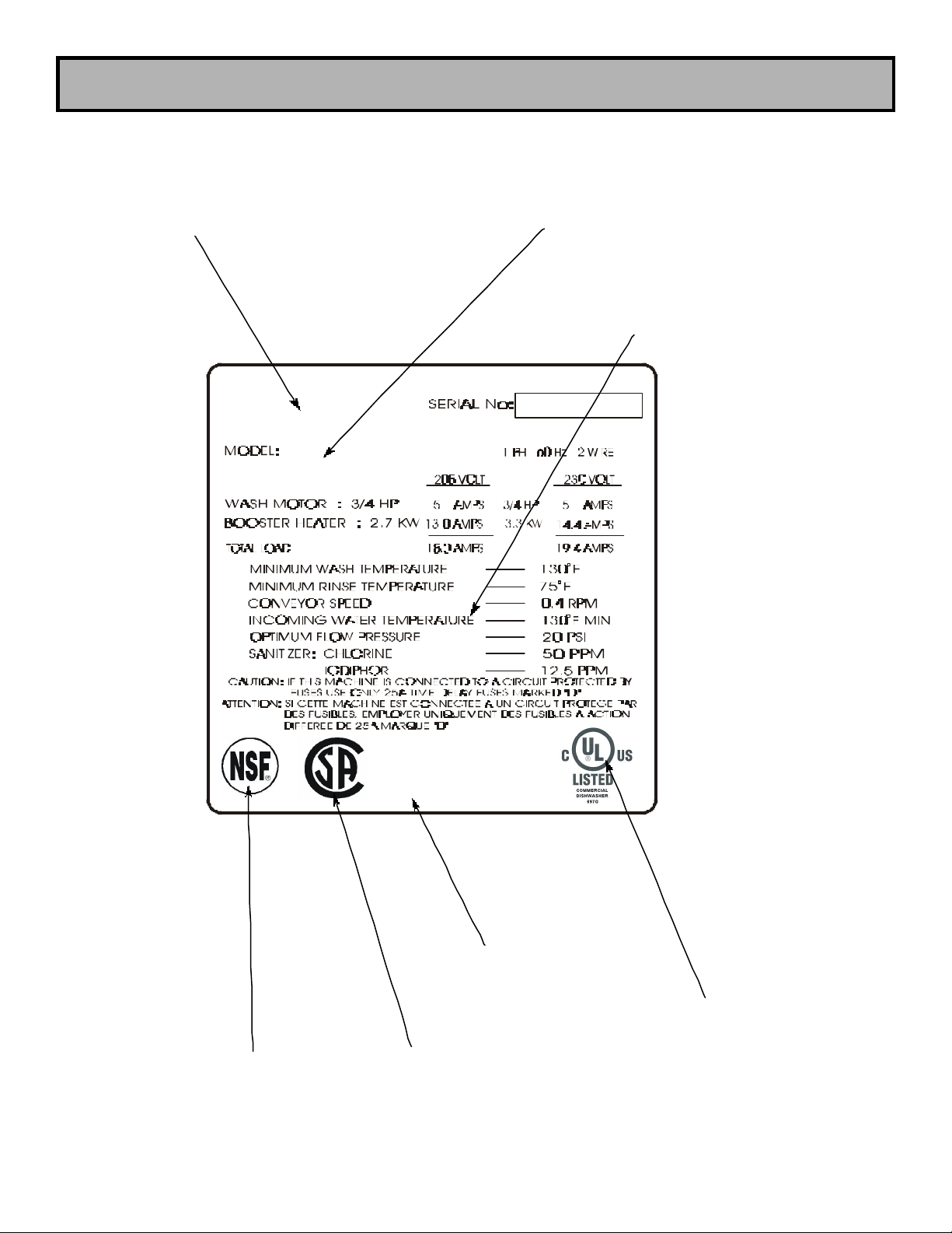
DETAIL OF A TYPICAL GLASSWASHER DATA PLATE
MANUFACTURER’S
LOGO
MODEL DESIGNATION
(I.E. CONSERVER GW-30)
MINIMUM PARAMETERS
SEE NOTE #1
NSF LOGO
SEE NOTE #2
MANUFACTURER’S
ADDRESS INFORMATION
C/US UL LOGO
SEE NOTE #3
CSA LOGO
SEE NOTE #4
2
Page 6
GENERAL
Before connecting, operating or adjusting this dishmachine, please read this manual carefully to
familiarize yourself with your unit and its proper operation.
This manual contains important operating, safety and maintenance information on your dishmachine. You must follow the instructions given in the manual to ensure that your warranty remains in
effect.
Notes Concerning Glasswasher Data Plates:
1) Minimum parameters must be met in order for this dish machine to function at its intended level
of operation and efficiency. Different machines from different manufacturers have different minimum
requirements. Follow those details found on the data plate of your machine, do not use the parameters listed on the example for this manual. If you are unsure, contact your nearest authorized
Jackson service representative. Failure to ensure that the machine meets the minimum parameters
as expressed on its individual data plate may result in sub-standard performance.
2) The NSF logo on the data plate indicates that this machine has been inspected,
reviewed, tested, and approved under NSF Standard 3 by NSF International Inc.,
formerly the National Sanitation Foundation. For more information concerning the NSF
mark, write to: NSF International Inc., 789 Dixboro Road, Ann Arbor, MI., 48105.
3) This symbol indicates that this product is Listed by Underwriter’s Laboratories Inc.
Representative samples of this product have been evaluated by UL and meet the
applicable U.S. and Canadian safety standards. For more information concerning this
mark, write to: Underwriter's Laboratories Inc., 333 Pfingsten Road, Northbrook, IL.,
60062-2096.
4) The CSA logo on the data plate indicates that this machine has been certified by
Canadian Standards Association Inc. as having met the applicable Canadian safety
standards. For more information concerning this mark, write to: CSA Inc., 178
Rexdale Blvd., Rexdale (Toronto), Ontario, Canada, M9W 1R3.
3
Page 7

INSTALLATION INSTRUCTIONS
NOTE: Before any connections are made, visually check the entire machine for any possible ship -
ping damage. If any damage is found, proceed to “CONCEALED DAMAGE OR MISSING PARTS”.
UNPACKING THE DISHWASHER
STEPS: 1. Remove all protective packing material from machine.
2. Place machine in its operating location and remove skid.
CAUTION: ENSURE WEIGHT OF MACHINE IS EVENLY DISTRIBUTED WHEN
REMOVING FROM SKID INTO POSITION.
3. Adjust all four (4) adjustable bullet (or flanged) feet so contact is made to floor.
CONCEALED DAMAGE OR MISSING PARTS
IMPORTANT: FOR YOUR PROTECTION, PLEASE READ AND OBSERVE THE FOLLOWING:
This dishwasher has been thoroughly inspected and carefully packed before leaving our warehouse.
Concealed loss or damage means loss or damage which does not become apparent until the dish-
washer has been unpacked. The contents may be damaged in transit due to rough handling even
though the carton may not show external damage.
If it is found that the shipment has concealed damage, PLEASE DO NOT RETURN IT TO JACKSON,
but notify the carrier (within 48 hours) asking them to send their agent to fill out an inspection report.
Save the cartons so he may inspect them and be sure to note in the report any black marks, creases, tears, crushed corners or any other marks indicating rough handling. Also, notify the JACKSON
dealer immediately.
If it is discovered that there are missing parts such as: strainers, rinse assembly, owner’s manual or
racks, please notify JACKSON immediately.
Prior to Installation, verify that the electrical service agrees with the specifications on the machine
data plate located on the right side and to the front of the machine. Refer to the data plate for machine
operating requirements, machine voltage, total amperage load and serial number.
For proper operation, the dishmachine should be leveled from side to side and from front to back.
Using a level placed on the flat area at top of unit, adjust leveling feet up or down.
NOTE: The dishwasher must be positioned and leveled before making any connections to
the unit.
4
Page 8

PLUMBING
NOTE: ALL CONNECTIONS MUST COMPLY WITH ALL APPLICABLE LOCAL, STATE AND
NATIONAL PLUMBING CODES.
The plumber is responsible that the water lines are THOROUGHLY FLUSHED BEFORE connecting
it to any manual or solenoid valve. It is necessary to remove all foreign matter such as chips (resulting from cutting or threading pipes), pipe joint compound or, if soldered fittings are used, bits of solder or cuttings from the lines. This debris, if not removed, may lodge in the valves and render them
inoperative.
Any valves fouled by foreign matter, and any expenses resulting from this fouling, are not the
responsibility of the manufacturer.
DRAIN LINE CONNECTION
All glasswashers have a gravity drain.
Ensure that this unit is installed in accordance with all applicable codes.
If a grease trap is required by code, it should have a flow capacity of 5 gallons per minute.
WATER SUPPLY CONNECTION
Cold water supply must have a capacity of 180 gallons per hour at 20 PSI flow pressure to the glasswasher. Hot water supply must be a minimum of 130 degrees F. with a capacity of 10 gallons per hour
at 20-25 PSI flow pressure. Incoming hot and cold water service connection (supplied by customer)
must be a 1/2” pipe size minimum with shut off valve.
Install the water supply line (1/2” pipe size minimum) to the dishmachine using copper pipe. It is recommended that a water shut-off valve be installed in each water line between the main supply and
machine to allow access for service.
In areas where the water pressure fluctuates or is greater than the recommended pressure a water
pressure regulator valve must be installed. This item should be located before the solenoids and after
the shut-off valve.
Do not confuse Static Pressure with Flow Pressure. Static Pressure is the line pressure with no flow.
All valves and services are closed. Flow Pressure is the pressure in the fill line when the fill valve is
open and the machine is in the fill (hot)/rinse (cold) cycle.
It is recommended a shock absorber (not supplied) be installed in the incoming water line. This prevents line hammer (hydraulic shock), induced by the solenoid valve as it operates, from causing damage to the equipment.
5
Page 9

ELECTRICAL
WARNING: Electrical and grounding connections must comply with applicable portions of
the National Electrical Code ANSI / NFPA 70 (latest edition) and/or other electrical codes.
WARNING: Disconnect electrical power supply and place a tag or lock at the disconnect
ELECTRICAL POWER CONNECTION
1. Refer to glasswasher electrical data decal located on the right side of the door, for
machine voltage, amperage load and serial number.
2. Remove electrical box cover by removing two screws at the bottom corners and lift
up and off. Let cover rest against plumbing assembly.
3. Install conduit from rear of machine to hole in rear of electrical box below terminal
block and ground lug.
4. Route power wires, L1, L2 and Ground to terminal block and lug.
5. Install power wires, L1, L2 and Ground to appropriate terminals marked L1, L2 at the
terminal block. Install ground wire into grounding lug provided. NOTE: It is suggested
that “DE-OX” or similar antioxidation agent be used on all incoming connections.
WARNING: INSURE ALL WIRING CONNECTIONS TO TERMINAL BLOCK AND
GROUND LUG ARE PROPERLY TIGHTENED AND TORQUED
ACCORDINGLY.
6. Apply power to glasswasher. WARNING: CHECK INCOMING POWER AT TERMINAL
BLOCK FOR PROPER VOLTAGE PER MACHINE’S ELECTRICAL DATA DECAL.
7. Replace electrical box cover, turn off power to machine and at service breaker. Mark
breaker for glasswasher and advise proper personnel.
6
Page 10

CHEMICAL DISPENSING EQUIPMENT
TO READY CHEMICAL
The glasswasher machine is supplied with Detergent, Rinse Additive and Santizer dispensing peripumps. Locate the open ends of the chemical tubes with the tube stiffeners and place each one in
the appropriate container.
A. -Red Tubing = Detergent
B.- Blue Tubing = Rinse Aid
C.- WhiteTubing = Sanitizer.
NOTE: IF USING IODIPHOR AS BOTH A RINSE AID AND SANITIZER, PLACE BOTH TUBE
STIFFENERS INTO THE CONTAINER.
PRIMING PERI-PUMPS
Peristaltic pumps need priming when the machine is first installed or if for some reason the chemical
lines have been removed and air is allowed to enter.
CAUTION: Water must be in the sump and wash tank prior to the dispensing of chemicals.
Sanitizer in concentration is caustic and may cause damage without dilution.
1. Verify that the proper chemical tube stiffener inlet is in the proper container.
2. Use the Toggle Switches on the right side of Control Box to prime each pump.
3. To prime the pumps hold the switch in the momentary position until chemical can be
observed entering the sump.
4. Detergent is dispensed proportionally during the wash fill. The amount of detergent
may need to be increased or decreased depending on water quality and type of
detergent. It is adjusted by turning potentiometer on the speed control board
clockwise to increase, counter- clockwise to decrease.
5. Rinse additive is dispensed proportionally into the final rinse. The amount of rinse aide
may need to be adjusted depending on water hardness and results. It is adjusted by
turning potentiometer on the speed control board clockwise to increase, counterclockwise to decrease.
6. Sanitizer either chlorine or iodine is dispensed proportionally into the final rinse. The
amount of sanitizer may need to be adjusted depending on concentration and the
type of sanitizer used. It is adjusted by turning potentiometer on the speed control
board clockwise to increase, counter-clockwise to decrease.
8
Page 11

DETERGENT CONTROL
Using detergent in the proper amount can become, in time, a source of substantial savings. In some
cases, controlling detergent use can depend on a number of variables in the warewashing cycle. Of
course, a qualified water treatment specialist can tell you what is needed for maximum efficiency from
your detergent, but you should know some basics so you’ll understand what he is talking about.
1. The amount of detergent needed is related in one way to water hardness. Water hardness is
the amount of dissolved calcium and magnesium in the supply. The greater the amount of dis solved solids the harder the water. Hard water does not allow the detergent to act as it should
in the washing cycle, and requires more detergent to do the job. Soft water actually enhances
the effect of the detergent and you can use less to do the job and will also eliminate scaling and
line build-up, a major problem with hard water.
2. It is important to understand water hardness because of the problems it causes. You may, for
instance, be adding rinse agents to reduce water spotting, when the problem may be hard
water. Minerals in hard water are left on glassware and dishes after water evaporates, which
may be the cause of the water spots.
3. Remember, treated water may be an advantage for your warewashing system and a
disadvantage in other areas. For instance, coffee made with soft water may have an acid or
bitter flavor; so magnetically treat the water for your warewashing system to give better
results and use less detergent.
4. Once your water problems are solved, make sure that your dishmachine operators keep the
detergent dispenser full and in operating order at all times.
In addition to the points outlined, other factors about the detergent are important too. Menu items, for
instance, call for an extra-powerful detergent. Extra-hard water may require a different type of detergent.
Also, remember that more detergent won’t do a better job of cleaning--in fact it may do worse. Too
much soap can build up just like hard water scale, so always use the recommended amount.
8
Page 12

DAILY OPERATION
TO FILL GLASSWASHER WITH WATER
1. Remove wash tank strainer and place overflow stopper into fitting at the bottom of
the wash tank.
2. Open incoming water shut-off valves on cold and hot water lines.
3. Place the power switch to the “FILL” position, machine will fill and shut off by itself.
4. Check water level, should be near top of the overflow stopper.
5. Replace wash strainer.
TO RUN THE CONSERVER GW/CONSERVER GW-30 GLASSWASHER
1. After filling with water, turn the power switch to the “ON” position, the rack will automatical
ly being to rotate.
2. Place glasses on the rack.
3. When the glasses have completed the cycle, the paddle switch will be activated, shutting
the unit down.
4. Remove the clean glasses.
5. The rack will begin to rotate again.
TO RUN THE CONSERVER GW-30RU GLASSWASHER
1. After filling with water, turn the power switch to the “ON” position.
2. Place glasses on the rack, dirty side down.
3. Turn the start knob to the “ON” position. The Conserver GW-30RU will now run.
4. As ware comes out on the rinse side, you may remove it from the rack. The rack will
remain in motion for 7-1/2 minutes.
5. Turn the start knob again to restart the unit.
SHUTDOWN AND CLEANING OF THE GLASSWASHER
1. Ensure that all ware placed on the rack is able to complete the cycle and is cleaned prior
to shutting the power switch to “OFF”. Shut off the water supply to the unit.
2. Remove the drain boards, rack cylinder and rack. Clean and allow to dry before rein
stalling into the machine.
3. Remove the sump and drain tank strainers. Clean completely and allow to dry before rein
stalling into the machine.
4. Remove the stand pipe by grasping by the HANDLE and removing from the drain tank.
Clean and allow to dry before reinstalling into the machine. CAUTION: Water in the drain
tank may be hot, allow the water to cool down and always remove the stand pipe through
the use of the handle. Never place your hand in the water within the drain tank.
5. Remove the curtains and spray down using a mild soap and rinse with clean water. Allow
to dry completely before reinstalling into the machine.
6. Remove the rack wrap from inside the tub. Clean and allow to dry completely vefore rein
stalling into the machine.
7. Remove the wash and rinse arms. Inspect them for clogged or obstructed nozzles.
8. Wipe out the inside of the glasswasher tub, removing any and all debris.
9. Reinstall all components previously removed after they have been allowed to dry.
9
Page 13

INSTALLATION CHECKLIST
CHECK OFF THE FOLLOWING ITEMS AS THEY ARE COMPLETED BEFORE PROCEEDING TO
OPERATION OF DISHWASHER.
Has dishmachine been checked for concealed damage?
Is dishmachine properly ventilated?
Has dishmachine been properly leveled?
Is the drain plumbing installed with air gap?
Service voltage correct to data decal?
Machine properly grounded?
Machine circuit breaker sized correctly?
Machine circuit breaker marked for dishwasher?
Hot water supply flushed for debris?
Hot water supply at 130 F. minimum?
Hot water supply at 20 P.S.I. flowing pressure?
A water pressure regulator is needed?
Are both the cold and hot water supply line 1/2 inch minimum?
Has machine voltage been checked at L1 and L2 to ensure a high/wild leg is not
connected to either L1 or L2? (Voltage exceeding 250 VAC to ground could indicate a
high leg.)
Are the chemical tubes installed in the proper supply container ?
Have the peri-pumps been primed ?
Is the sanitizing peri-pump been adjusted to inject 50 parts per million chlorine solution or
12 parts per million of Iodiphor into the final rinse line ?
Does the drain plumbing slope correctly to the floor drain?
10
Page 14

SEQUENCE OF OPERATION - CONSERVER GW/GW-30
REFER TO ELECTRICAL DIAGRAM FOR FUNCTION AND REFERENCE DESIGNATIONS.
1. All removable parts have been re-installed into Glasswasher and it is ready to operate.
2. Power switch (S1) is turned to the “Fill” position.
A. Hot water valve (HWV) is energized filling tank.
3. Tank is filled to operating level.
A. Top (FS1) and bottom (FS2) float switches close.
B. Wash tank fill relay (R2) is energized
C. Wash tank fill relay N.O. holding contact closes.
D. Wash tank fill relay N.O. contact closes energizing wash heater relay (R1).
E. Wash heater relay N.O. contacts close energizing the tank heater (H1).
F. Wash tank fill relay N.C. contact opens de-energizing hot water valve (HWV)
The Glasswasher is now ready for operation.
4. Power switch (S1) is turned to the “ON” position.
A. Conveyor drive motor (M1) is energized.
B. Wash pump motor (M2) is energized.
C. Cold water valve (CWV) is energized.
D. Power is supplied to speed control (SC) for the peri pump (DM, RM, & SM) operation.
The Glasswasher will continue to operate until either a glass trips the conveyor limit switch (S2) or
the power switch (S1) is turned to the “OFF” position.
5. Glasses trip the conveyor limit switch (S2).
A. Conveyor drive motor (M1) is de-energized.
B. Wash pump motor (M2) is de-energized.
C. Cold water valve (CWV) is de-energized.
D. The unit will not run until the glass(es) are removed from the unload side of the unit.
Once this is done steps 4A, 4B & 4C will start and more glasses can be placed in the
unit for washing.
The wash tank heater (H1) has two (2) methods of protection to prevent damage to the
heater.
6. Bottom float switch (FS2) opens due to low water.
A. Wash tank fill relay (R2) is de-energized.
B. Wash tank fill relay N.O. holding contact opens.
C. Wash heater relay N.O. contacts open de- energizing the tank heater (H1).
6. High limit thermostat (TS1) opens due to sheath temperature exceeding preset limit.
A. Heat contactor (R1) is de-energized.
B. Wash heater relay N.O. contacts open de-energizing the tank heater (H1).
C. Proper water temperature will not be maintained for cleaning glasses.
11
Page 15

TROUBLESHOOTING SECTION (CONSERVER GW/GW-30)
Branch circuit breaker tripped or fuse
upper and lower floats are working. If
Symptom
WARNING: Inspection, testing and repair of electrical equipment should only be performed
by a qualified service technician. Many of the tests require that the unit have power to it
and live electrical components be exposed. USE EXTREME CAUTION WHEN TESTING THE
MACHINE.
Possible Cause Action
Dish machine will not run, no voltage
at wash relay terminals L1 and T1.
Electrical power not installed to
machine, service (main) power
disconnect off.
is blown.
Ensure electrical wiring is ran to
machine and service (main)
disconnect is on.
Reset or replace as required. Have
an electrician check machine amp
draw if problem keeps occuring.
Machine cycles continuously.
Machine will not fill, other functions
work.
Loose or broken connection to dish
machine.
Limit switch actuator is loose or has
fallen off.
Faulty limit switch. Replace switch.
No water supply to machine. Ensure that water is hooked up
Tighten, replace or repair as
required.
Reassembly/bend metal lever if
necessary.
properly to machine and that it is
turned on.
Faulty solenoid valve diaphragm or
coil.
Faulty float switch. Ohm out the switch to ensure that
Replace diaphragm and clean out
valve. Measure continuity on coil, if
there is none, replace the coil.
not, check float wiring to see if it is
correct; if so, replace float.
11
Page 16

TROUBLESHOOTING SECTION (CONSERVER GW/GW-30)
upper and lower floats are working. If
Loose wire connection to microswitch
Machine fills continuously, stops when
Symptom
WARNING: Inspection, testing and repair of electrical equipment should only be performed
by a qualified service technician. Many of the tests require that the unit have power to it
and live electrical components be exposed. USE EXTREME CAUTION WHEN TESTING THE
MACHINE.
Possible Cause Action
Machine fills continuously even with
no power to the dish machine.
Solenoid valve jammed/stuck in the
open position.
Check diaphragm and coil, replace
as required.
the unit is turned off.
Wash motor does not run, other
functions work.
Faulty float switch. Ohm out the switch to ensure that
not, check float wiring to see if it is
correct; if so, replace float.
Tighten wires.
or relay.
Faulty pump motor. Replace pump motor.
Mechanical binding in the pump. If motor has correct incoming
voltage, and the overload is tripping,
repair or replace the pump.
Page 17

TROUBLESHOOTING SECTION (CONSERVER GW/GW-30)
WARNING: Inspection, testing and repair of electrical equipment should only be performed
by a qualified service technician. Many of the tests require that the unit have power to it
and live electrical components be exposed. USE EXTREME CAUTION WHEN TESTING THE
MACHINE.
Symptom
Wash motor does not run; other
functions work.
Wash motor runs continuously.
Possible Cause Action
High or low voltage problem. Check voltage at motor and at power
terminal block. Ensure it meets the
electrical voltage specifiactions for
the dish machine.
Wash relay welded closed. Turn machine off. If wash relay does
not release, replace the contactor.
Low water pressure.
Water level is too low. Ensure that incoming water line
pressure meets the requirements on
dish machine data plate.
Wash arms clogged. Remove wash arms and clean.
Obstruction in pump housing. Disassemble and clear.
Page 18

TROUBLESHOOTING SECTION (CONSERVER GW/GW-30)
Symptom
WARNING: Inspection, testing and repair of electrical equipment should only be performed
by a qualified service technician. Many of the tests require that the unit have power to it
and live electrical components be exposed. USE EXTREME CAUTION WHEN TESTING THE
MACHINE.
Possible Cause Action
Low wash water pressure.
Pump impeller worn or broken. Replace pump.
Float stuck on float switch. Remove, clean and reinstall float
switch.
Machine keeps tripping service
breaker.
Power supply shorted to ground. Check for loose wires/burned
connection. Replace or repair as
required.
Pump impeller jammed. Disassembly and remove
obstruction.
Wash pump motor faulty. Check motor voltage and amp draw.
Service breaker too small. Replace with correctly sized breaker.
Page 19

TROUBLESHOOTING SECTION (CONSERVER GW/GW-30)
Check continuity through each poleof
Symptom
WARNING: Inspection, testing and repair of electrical equipment should only be performed
by a qualified service technician. Many of the tests require that the unit have power to it
and live electrical components be exposed. USE EXTREME CAUTION WHEN TESTING THE
MACHINE.
Possible Cause Action
Machine will not hold water.
Drain stopper not in place. Set drain stopper correctly in drain.
Drain fitting O-ring cut or missing. Replace O-ring.
Sanitizer pump runs continuously.
Sanitizer pump does not run during
cycle, but runs when primed.
Shorted prime switch. If there is not line voltage between
BLACK and ORANGE/BLACK wires
to prime switch, replace.
Faulty speed control board. Check operation of board. If not
working properly, replace.
Loose or broken wire. Tighten connections to microswitch.
Faulty speed control board. Check operation of board. If not
working properly, replace.
Faulty prime switch.
switch. If it fails, replace the switch.
Page 20

TROUBLESHOOTING SECTION (CONSERVER GW/GW-30)
Detergent not feeding, rinse aid feeds
Symptom
WARNING: Inspection, testing and repair of electrical equipment should only be performed
by a qualified service technician. Many of the tests require that the unit have power to it
and live electrical components be exposed. USE EXTREME CAUTION WHEN TESTING THE
MACHINE.
Possible Cause Action
Prime switch does not activate
sanitizer pump.
Faulty prime switch. With the prime switch in the prime
position, check for voltage between
BLACK and ORANGE/BLACK wires.
If line voltage, replace switch.
Loose wire to prime switch. Tighten wire connection.
Sanitizer pump doesn't run during
cycle or through prime switch.
okay.
Loose motor terminal wires. Tighten connections.
Faulty sanitizer pump motor. If you read line voltage at the
sanitizer motor terminals during the
sanitizer feed cycle, replace the
motor.
Faulty prime switch. Check the continuity through each
pole of the switch. If faulty, replace
the switch.
Faulty speed control board. Check operation of board. If not
working properly, replace.
Defective hose or squeeze tube. Replace hose or squeeze tube as
needed.
Page 21

TROUBLESHOOTING SECTION (CONSERVER GW/GW-30)
Symptom
WARNING: Inspection, testing and repair of electrical equipment should only be performed
by a qualified service technician. Many of the tests require that the unit have power to it
and live electrical components be exposed. USE EXTREME CAUTION WHEN TESTING THE
MACHINE.
Possible Cause Action
Rinse aid pump not feeding,
detergent feeds okay.
Faulty speed control board. Check operation of board. If not
working properly, replace.
Defective hose or squeeze tube. Replace hose or squeeze tube as
needed.
Wash heater does not work. (Note:
push wash heater contactor bar down
and take amperage reding. Amps
should be correct as stated on the
dish machine data plate).
If no amp draw, check wash heater
for continuity.
Wash heater relay will not energize
(no voltage at contactor coil).
Low voltage problem. Check incoming voltage to ensure it
If open or shorted, replace the
heater. If closed, replace the heater
contactor.
Check for continuity at wash
thermostat. If open, replace.
as what the data plate calls for.
Page 22

COMMENTS ON DRAWING/PARTS SECTION
On the following pages are several drawings calling out specific dimensions as well as part
number for the various items found on the glasswasher machines. Because of the similarities between all three models, many parts are not designated as being unit specific.
However, in the case of the Conserver GW-30 and Conserver GW-30RU, there are so few differences that unless otherwise specifically called out, you may use the Conserver GW-30
dimensions and parts when installing and servicing the Conserver GW-30RU.
Page 23

DIMENSIONS
F
25-1/4"
30-1/2"
H
7-1/2"
8-5/8"
LEGEND:
A - WATER INLET 1/2” IPS (C0LD)
B - WATER INLET 1/2” IPS (HOT)
C - DRAIN 2” NOMINAL
D - STANDARD WALL CLEARANCE: 2”
LETTER CONSERVER GW CONSERVER GW-30
E 26-1/4" 30-5/16"
G 14-3/4" 16-1/4"
I 18-11/16" 23-11/16"
E
F
G
H
I
14
Page 24

MAIN ASSEMBLY DRAWING
8, 9
11
10
3
5
7
6
20
19
2
1
4
16
12 13
14, 15
17
18
22
21
Page 25

MAIN ASSEMBLY (CONTINUED)
ITEM QTY DESCRIPTION CONSERVER GW CONSERVER GW-30
1 1 Curtain 8415-021-60-91 8415-002-00-62
2 1 Tub Weldment 5700-041-61-13 5700-001-98-91
3 1 Vacuum Breaker Assembly 5700-021-61-42 5700-021-61-42
4 2 Hose Clamp, 2-1/2" 4730-011-63-23 4730-011-63-23
5 1 Pump Discharge Hose 5700-011-63-03 5700-011-63-03
6 2 Hose Clamp, 1"
7 1 Wash Fill Tube 5700-021-63-01 5700-021-63-01
8 10 Hose Clamp, 25/32" 4730-011-63-22 4730-011-63-22
9 1 Hose, Wash Fill 5700-011-63-13 5700-011-63-13
10 3 Clamp, Plumbing
11 1 Wash Strainer Weldment 5700-021-61-78 5700-001-98-86
12 1 Wash Tank Weldment 5700-002-06-39 5700-001-98-69
13 1 Control Box Assembly 5700-031-62-24 5700-002-04-83
14 1 Rinse Strainer Weldment 5700-021-61-79 5700-001-98-88
15 1 Drain Weldment 5700-031-61-99 5700-001-98-78
16 1 Injection Manifold Assembly 5700-031-61-59 5700-031-61-59
17 1 Frame Weldment 5700-031-61-90 5700-001-99-99
18 4 Bullet Feet 5340-108-01-03 5340-108-01-03
19 1 Wash Motor 6105-121-61-64 6105-121-61-64
20 1 Suction Hose Assembly 5700-011-63-26 5700-002-02-68
21 1 Front Door Assembly 5700-031-61-60 5700-002-00-42
22 1 Incoming Plumbing Assembly 5700-031-61-51 5700-031-61-51
NOTE: ITEMS 12, 16, AND 17 ARE DIFFERENT ON THE CONSERVER GW-30RU AND
HAVE SPECIFIC PAGES IN THIS MANUAL. PLEASE REFER TO THOSE PAGES WHEN
ORDERING YOUR SERVICE ITEMS.
Page 26

CONTROL BOX ASSEMBLY
31Electrical Box Cover
5700-021-61-14
61Speed Control Board
5945-011-46-24
131Transformer
5950-011-61-67
QTY DESCRIPTION MFG No.
1 1 Electrical Box Bottom Weldment 5700-031-62-27
2 4 Screw, 10-32 x 1/2", Ph. Truss Head 5305-011-59-67
4 1 Liquid Level Control 6680-011-61-68
5 7 6-32 Locknut w/ Nylon Insert 5310-375-03-00
7 1 Speed Control Board Bracket 5700-021-62-28
8 1 Terminal Block 5940-500-09-61
9 1 Terminal Block Spacer 5700-011-40-05
10 1 Ground Lug 5940-200-76-00
11 1 Contactor 5945-109-03-69
12 9 10-24 Locknut w/ Nylon Insert 4730-111-48-87
7
6
5
4
1
8
9
2
3
10
11
12
13
Page 27

ELECTRICAL BOX COVER ASSEMBLY
ITEM QTY DESCRIPTION MFG No.
1 3 Motor, Peri-Pump, 14 RPM 4320-011-63-33
2 3 Switch, Prime 5930-011-49-54
3 1 Decal, Detergent Prime 9905-011-64-80
4 1 Decal, Rinse Prime 9905-011-64-81
5 1 Decal, Sanitizer Prime 9905-011-65-22
6 1 Top, Electrical Box 5700-021-60-70
1
6
3
REFER TO PAGE ENTITLED
‘PERISTALIC PUMP ASSEMBLY”
2
5
4
Page 28

PERISTALTIC PUMP ASSEMBLY
4A1Roller Blade, Sanitizer/Rinse Aid
43420-111-65-27
7*3Peri Pump Motor (14 RPM) Rinse Additive
4320-111-35-13
1Peri Pump Assembly, Detergent
5700-031-65-20
ITEM QTY DESCRIPTION MFG No.
1 4 Screw, 6-32 x 3/4" Phillips Pan Head 5305-011-37-05
2 2 Screw, 8-32 x 1/2" Phillips Flat Head 5305-011-37-06
3 2 Screw, 8-32 x 3/8" Phillips Flat Head 5305-011-37-07
4 1 Anko Roller, Detergent 4320-111-36-70
5 1 Housing, Front 4320-111-37-08
6 1 Housing, Rear Assy 4320-111-37-09
8* 1 Peri Pump Squeeze Tube, Detergent 5700-111-35-29
8A* 2 Peri Pump Squeeze Tube - San./Rinse 5700-111-65-21
2 Peri Pump Assembly, Rinse & Sanitizer 5700-031-63-34
* = ITEM NOT SHOWN.
30
Page 29

OLD STYLE RACK HUB ASSEMBLY (CONSERVER GW)
1
2
SERVICE NOTE:
ONCE ITEM 1 IS PRESSED IN,
IT IS RECOMMENDED TO
REAM/DRILL THE HOLE TO 5/16”
DIAMETER
A * INDICATES THAT THIS ITEM IS NOT SHOWN.
ITEM QTY DESCRIPTION MFG No.
1 1 Hub Sleeve 5700-011-61-07
2 1 Rack Hub Plate Weldment 5700-011-61-84
*3 4 Locknut, 1/4"-20 with Nylon Insert 5310-374-01-00
*4 4 Bolt, 1/4"-20 x 3/8" Long 5305-274-01-00
Page 30

GEAR DRIVE ASSEMBLY
1
2
6
11
12
8
7
9
10
5
4
3
ITEM QTY DESCRIPTION MFG No.
1 1 Hub 5700-011-61-21
2 1 Hub Spacer 5700-011-61-07
3 1 Gear 6105-011-70-88
4 1 Screw, Set, 1/4"-20 5305-002-10-14
5 4 Bolt, Hex, 10-32 x 3/8" Long 5306-011-63-29
6 1 Limit Switch 5930-011-61-65
7 1 Switch Box Weldment 5700-021-62-41
8 1 Gear Box Weldment 5700-002-02-45
9 1 Motor Mounting Box 5700-002-00-61
10 1 Gear Drive Motor 6105-011-70-80
11 4 Liquid Tight Fitting 5975-011-49-03
12 1 Liquid Tight Fitting 5975-011-65-51
Page 31

INCOMING PLUMBING ASSEMBLY
52Check Valve, Flap, 3/8" FNPT x 3/8" FNPT
4820-011-61-56
92Cover, S-45 Solenoid
5975-011-62-70
ITEM QTY DESCRIPTION MFG No.
1 2 Coupling, 1/2" FNPT x 3/8" FNPT, Brass 4730-011-61-52
2 2 Tee, 3/8" x 3/8" x 3/8" MNPT, Brass 4730-011-61-53
3 2 S-45 Eaton Solenoid Valve w/ Strainer 4810-011-61-54
4 2 Fitting, 3/8" MNPT x 90 Degree to 1/2" OD 4730-011-61-55
6 3 Nipple, 3/8" MNPT x 2-1/2" Long 4730-011-61-57
7 1 Ball Valve, 3/8" FNPT x 3/8" FNPT 4820-011-61-58
8 2 3/8" Brass Coupling 4730-011-62-56
Page 32

INJECTION MANIFOLD ASSEMBLY
ITEM QTY DESCRIPTION MFG No.
1 1 Injection Manifold 5700-031-60-37
2 1 Gauge, 0 - 30 PSI, 1/4" NPT 6685-011-64-29
3 2 Fitting, 1/4" MNPT Str. To 1/2" OD, Plastic 4730-011-61-62
4 1 Injection Manifold Bracket Assembly 5700-011-61-61
5 2 Screw, 10-32 x 1-1/4", Ph. Truss Head 5305-011-66-03
6 2 Fitting, 1/4" MNPT 90 Deg. X 1/4", Plastic 4730-111-48-87
7 1 Thermometer 6685-111-35-30
2
5
1
7
3
4
6
Page 33

VACUUM BREAKER ASSEMBLY
31Plate, Vacuum Breaker
5700-011-61-46
*62Locknut, 1/4"-20 with Nylon Insert
5310-374-01-00
*102Clamp, Mini, 7/16" - 25/32"
4730-011-36-05
ITEMS 1 THROUGH 5 CAN BE
ORDERED AS ONE ASSEMBLY
USING PART NUMBER:
5700-021-61-42.
3
1
2
4
ITEMS INDICATED
WITH A * ARE NOT
SHOWN.
5
ITEM QTY DESCRIPTION MFG No.
1 1 Vacuum Breaker 4820-011-61-43
2 2 Nipple, 3/8" NPT x 8" Long 5700-021-61-44
4 2 Jam Nut 5310-011-61-45
5 2 3/8" NPT x 1/2" ID Hose Barb 4730-011-61-47
*7 1 Hose, Rinse Feed, 1/2" ID x 11" Long 5700-011-63-09
*8 1 Hose, 1/2" Reinforced x 27" (Conserver GW) 5700-011-63-11
*9 1 Hose, 1/2" Reinforced x 54" (GW-30 only) 5700-002-02-71
Page 34

WASH TANK ASSEMBLY
7
5
6
4
9
12
11
1
8
13
3
10
2
Page 35

DRAIN TANK ASSEMBLY (CONTINUED)
31Thermostat
5930-510-02-79
61Wash Strainer Weldment
5700-021-61-78
131O-Ring
5330-400-03-08
31Thermostat
5930-510-02-79
61Wash Strainer Weldment
5700-001-98-86
131O-Ring
5330-400-03-08
CONSERVER GW WASH TANK ASSEMBLY
ITEM QTY DESCRIPTION MFG No.
1 1 Wash Heater, 3 KW 4540-021-61-66
2 1 Thermometer 6685-111-35-30
4 1 Overflow Tube Weldment 5700-021-62-22
5 1 Drain Tank Weldment 5700-002-06-39
7 1 Float Switch 6680-121-70-16
8 4 5/16" Split Lock Washer 5311-275-01-00
9 1 Wash Heater Gasket 5330-011-61-34
10 4 5/16"-18 S/S Hex Nuts 5310-275-01-00
11 1 Heater Cover 5700-021-62-39
12 2 10-24 Nylon Lock Nut 5310-373-01-00
CONSERVER GW-30 WASH TANK ASSEMBLY
ITEM QTY DESCRIPTION MFG No.
1 1 Wash Heater, 3 KW 4540-021-61-66
2 1 Thermometer 6685-111-35-30
4 1 Overflow Tube Weldment 5700-021-62-22
5 1 Drain Tank Weldment 5700-001-98-69
7 1 Float Switch 6680-121-70-16
8 4 5/16" Split Lock Washer 5311-275-01-00
9 1 Wash Heater Gasket 5330-011-61-34
10 4 5/16"-18 S/S Hex Nuts 5310-275-01-00
11 1 Heater Cover 5700-002-02-96
12 2 10-24 Nylon Lock Nut 5310-373-01-00
Page 36

RINSE SUMP ASSEMBLY
1
2
CONSERVER GW
ITEM QTY DESCRIPTION MFG No.
1 1 Rinse Strainer Weldment 5700-021-61-79
1 1 Drain Weldment 5700-031-61-99
CONSERVER GW-30/CONSERVER GW-30RU
ITEM QTY DESCRIPTION MFG No.
1 1 Rinse Strainer Weldment 5700-001-98-88
1 1 Drain Weldment 5700-001-98-78
Page 37

WASH & RINSE ARMS
PART NO. 5700-031-60-84
CONSERVER GW-30/GW-30RU
PART NO. 5700-001-99-06
CONSERVER GW
WASH ARM
2 PER UNIT
WASH ARM
2 PER UNIT
CONSERVER GW
RINSE ARM
2 PER UNIT
PART NO. 5700-031-61-23
CONSERVER GW-30/GW-30RU
RINSE ARM
2 PER UNIT
PART NO. 5700-001-99-07
Page 38

WASH & RINSE MANIFOLDS
ARM RETAINING SCREW
WASH MANIFOLD WELDMENT
WASH MANIFOLD ASSEMBLY
1 PER UNIT
WASH MANIFOLD WELDMENT - 5700-031-60-95
ARM RETAINING SCREW
2 PER ASSEMBLY
PART NO. 5305-011-63-54
RINSE MANIFOLD WELDMENT
ARM RETAINING SCREW
RINSE MANIFOLD ASSEMBLY
1 PER UNIT
RINSE MANIFOLD WELDMENT - 5700-031-60-94
ARM RETAINING SCREW
2 PER ASSEMBLY
PART NO. 5305-011-63-54
Page 39

RACK WRAP ASSEMBLY
11Rack Wrap Weldment
5700-031-62-43
32Locknut, 1/4"-20, with Nylon Insert, LP
5310-374-02-00
THIS ENTIRE ASSEMBLY CAN BE
ORDERED USING PART NUMBER
5700-031-61-91.
2
3
1
CONSERVER GW
ITEM QTY DESCRIPTION MFG No.
2 2 Rack Support Rollers 5700-011-60-83
CONSERVER GW-30/GW-30RU
ITEM QTY DESCRIPTION MFG No.
1 1 Weldment, Rack Wrap (Conserver GW-30) 5700-002-11-59
2 2 Rack Support Rollers 5700-011-60-83
3 2 Locknut, 1/4"-20, with Nylon Insert, LP 5310-374-02-00
Page 40

LEFT DRAIN BOARD ASSEMBLY
21Splash Guard
5700-021-61-00
42Locknut, 10-32 with Nylon Insert
5310-373-02-00
2
3
4
1
ITEM QTY DESCRIPTION MFG No.
1 1 Drain Board Left (Conserver GW Only) 5700-031-61-02
1 1 Drain Board Left (Conserver GW-30 Only) 5700-001-98-57
3 2 Screw, 10-32 x 3/8" Long, Truss Hd. 5305-173-12-00
Page 41

RIGHT DRAIN BOARD ASSEMBLY
22Screw, 10-32 x 3/8" Long, Truss Head Ph.
5305-173-12-00
41Limit, Paddle Switch
5700-011-60-99
3
2
4
1
ITEM QTY DESCRIPTION MFG No.
1 1 Drain Board Right (Conserver GW Only) 5700-031-61-01
1 1 Drain Board Right (Conserver GW-30 Only) 5700-001-98-59
3 2 Locknut, 10-32 with Nylon Insert 5310-373-02-00
Page 42

DRIVE MOTOR ASSEMBLY (ORIGINAL STYLE)
7
10
9
8
12
2
4
11
1
3
5
6
Page 43

DRIVE MOTOR ASSEMBLY (ORIGINAL STYLE)(CONTINUED)
34Screw, 8-32 x 3/8" Long, Round Head
5305-172-02-00
81Starwasher, #10-24, Ecternal Tooth
5311-273-02-00
121AK Fastener, 10-32
5340-111-58-10
ITEM QTY DESCRIPTION MFG No.
1 1 Mounting Plate Cover 5700-011-70-20
2 1 Gearmotor, AC Unidirectional 6105-011-70-80
4 4 Lockwasher, #8, External Tooth 5311-272-01-00
5 4 Fitting, Liquid Tight, .231 ID x .394 OD 5975-011-49-03
6 1 Connector, Liquid Tight, .27 to .48 5975-011-59-50
7 1 Cover, Motor Mounting 5700-021-62-40
9 1 Screw, 10-32 x 3/8" Long, Truss Hd. 5305-173-12-00
10 2 Terminal, Bullet, Red 5940-200-74-00
11 3 Terminal, Bullet, Recpt, Red 5940-200-56-00
Page 44

DOOR ASSEMBLY
4
1
2
THE ENTIRE DOOR ASSEMBLY CAN BE ORDERED USING THE FOLLOWING NUMBERS:
CONSERVER GW: 5700-002-09-85
CONSERVER GW-30/GW-30RU: 5700-002-00-42
3
ITEM QTY DESCRIPTION MFG No.
1 1 Door Weldment - Conserver GW 5700-002-09-86
1 1 Door Weldment - Conserver GW-30 5700-002-00-43
2 1 Paddle-Latch Assembly 5340-001-96-30
3 8 Screw, 10-24 x 3/4" Long, Ph. Truss Head 5305-173-03-00
4 2 Nylon Lift-Off Hinges 5340-021-62-04
Page 45

CONSERVER GW ORIGINAL STYLE DOOR ASSEMBLY
21Door Handle
5340-021-62-05
52Nylon Lift-Off Hinges
5340-021-62-04
2
4
3
1
5
THE ENTIRE ASSEMBLY MAY BE ORDERED
USING PART NO. 5700-031-61-60.
ITEM QTY DESCRIPTION MFG No.
1 1 Door Weldment 5700-031-61-94
3 1 Ball Plunger 5700-011-34-06
4 10 Screw, 10-24 x 3/8" Long 5305-173-03-00
Page 46

CURTAIN/CURTAIN ROD
CONSERVER GW CURTAIN
PART NO. 8145-021-60-91
CONSERVER GW-30/GW-30RU CURTAIN
PART NO. 8145-002-00-62
NSF
CONSERVER GW CURTAIN ROD
PART NO. 5700-011-60-90
CONSERVER GW-30GW-30RU CURTAIN ROD
PART NO. 5700-002-00-63
Page 47

CURTAIN HOOK/HUB CYLINDER
CONSERVER GW/GW-30/GW-30RU
CURTAIN HOOK
2 PER UNIT
PART NO. 5700-011-61-04
CONSERVER GW/GW-30/GW-30RU
HUB CYLINDER
1 PER UNIT
PART NO. 5700-002-02-09
Page 48

MANIFOLD GASKET/GLASS RACK/ACTUATOR ASSEMBLY
WASH/RINSE MANIFOLD GASKET
CONSERVER GW/GW-30/GW-30RU
2 PER UNIT
PART NO. 5330-111-42-81
GLASS RACK
1 PER UNIT
CONSERVER GW P/N 5700-031-60-79
CONSERVER GW-30/GW-30RU
P/N 5700-031-92-11
ACTUATOR ASSEMBLY
CONSERVER GW/CONSERVER GW-30
1 PER UNIT
P/N 5700-021-61-48
TO ORDER THE BOLT ONLY USE
P/N 5306-011-63-29
Page 49

CONSERVER GW/CONSERVER GW-30
ELECTRICAL DIAGRAM
208/230 volt - 60 hertz - single phase
15
Page 50

CONSERVER GW-30RU
ELECTRICAL DIAGRAM
208/230 volt - 60 hertz - single phase
Page 51

JACKSON MAINTENANCE & REPAIR CENTERS
CALIFORNIA
COLORADO
FLORIDA
Jones-McLeod
P & D Appliance
GCS Service, Inc. #60
GCS Service, Inc. #15
Jones-McLeod
P & D Appliance
Metro Appliance
CONNECTICUT
GCS Service, Inc. #06
GCS Service, Inc. #14
GCS Service, Inc. #24
DELAWARE
GCS Service, Inc. #13
GCS Service, Inc. #78
Food Service
GCS Service, Inc. #24
GCS Service, Inc. #44
Jones-McLeod
GCS Service, Inc. #52
GEORGIA
Elmer Schultz Service
GCS Service, Inc. #16
Bromley Parts & Service
GCS Service, Inc. #84
EMR Service Division
2200 Norcross Pkwy, Suite 210
Southeastern
Food Equipment
Barkers Food Machinery
Service
Restaurant Applaince
Commercial Parts &
1616 7th Avenue North 4220-C Roseville Road 10525 East 40th Ave. 3373 N. W. 168th Street
Birmingham, AL 35203 North Highlands, CA 95660 Suite 206 Miami, FL 33056
(205) 251-0159 (916) 974-2772 Denver, CO 80239 (305) 621-6666
(800) 821-1150 (800) 824-7219 (303) 371-9054 (800) 766-8966
(205) 322-1440 fax (916) 974-2774 fax (800) 972-5314 (305) 621-6656 fax
(303) 371-4754 fax
Commercial Appliance
854 Lakeside Drive 100 South Linden Avenue
Mobile, AL 36693 S. San Francisco, CA 94080 1640 South Broadway
(334) 666-7278 (650) 635-1900 Denver, CO 80210
(800) 237-9859 (800) 424-1414 (303) 778-1126
(334) 661-0223 fax (650) 635-1919 fax (800) 525-3532
(303) 778-0268 fax
Equipment
Service
7219 Roosevelt Way NE Irwindale, CA 91706 302 Murphy Road 350
Seattle, WA 98115 (626) 960-9390 Hartford, CT 06114 Tampa, FL 33619
(206) 524-8200 (800) 258-6999 (860) 549-5575 (813) 626-6044
(800) 433-9390 (626) 337-4541 fax (800) 723-1562 (800) 282-3008
(206) 525-2890 Fax (860) 527-6355 fax (813) 621-1174 fax
5367 Second Street
8416 Laurel Fair Circle
Building 6, Suite 114
Tampa, FL 33610
(813) 663-0313
(800) 282-4718
(813) 663-0212 fax
1100 East Pico Blvd
Los Angeles, CA 90021
5052 South 40th Street (213) 683-2090 2101 Parkway South Orlando, FL 32811
Phoenix, AZ 85040 (800) 327-1433 Broomall, PA 19008 (407) 841-2551
(602) 474-4510 (213) 683-2099 fax (610) 356-6900 (800) 338-7322
(800) 510-3497 (610) 356-2038 fax (407) 423-8425 fax
(602) 470-4511 fax
111
Authorized Commercial
4832 South 35th. St. (800) 540-0719 Philadelphia, PA 19123 (334) 666-7278
Phoenix, AZ 85040 (714) 542-4787 fax (215) 925-6217 (800) 237-9859
(602) 234-2443 (800) 441-9115 (334) 661-0223 fax
(800) 824-8875
(602) 232-5862 fax 360 Littlefield
10th & Ringo (650) 871-4019 FAX (302) 655-8900 (770) 452-7322
P.O. Box 1688 (800) 225-0599 (800) 334-3599
Little Rock, AR 72202
(501) 374-0281 9030 Kenamar Drive, Suite 313
(800) 482-9269 San Diego, CA 92121
(501) 374-8352 fax (619) 549-8411 106 Willamsport Circle
Service
3717 Cherry Road (800) 235-6516
Memphis, TN 38118 (770) 446-3157 fax
(901) 366-4587
(800) 262-9155
(901) 366-4588 fax
Santa Ana, CA 92705 817 N. Third Street 854 Lakeside Drive
(714) 542-1798 P. O. Box 3564 Mobile, AL 36693
(215) 925-6208 fax
S. San Francisco, CA 94080
(650) 635-0720 36 Belmont Ave. 3127 Presidential Dr.
(800) 969-4427 Wilmington, DE 19804 Atlanta, GA 30340
(302) 656-3673 FAX (770) 452-7473 fax
(800) 422-7278 Salisbury, MD 21804
(619) 549-2323 fax (410) 543-8197 Norcross, GA 30071
(410) 548-4038 fax (770) 446-6177
4305 Vineland Rd., Suite G-12
Restaurant Service
16
Page 52

JACKSON MAINTENANCE & REPAIR CENTERS
GEORGIA (cont)
ILLINOIS (cont)
KENTUCKY (cont)
MARYLAND (cont)
GCS Service, Inc. #80
Certified Service Center
EMR Service Division
INDIANA
EMR Service Division
HAWAII
EMR Service Division
LOUISIANA
IDAHO
IOWA
Bana Parts, Inc.
Ron's Service
Goodwin-Tucker Group
MASSACHUSETTS
GCS Service, Inc. #09
Bana Parts, Inc.
Cone's Repair Service
MAINE
ILLINOIS
KANSAS
GCS Service, Inc. #09
GCS Service, Inc.#12
GCS Service, Inc. #82
Ace Service Co.
Cone's Repair Service
KENTUCKY
Certified Service Center
GCS Service, Inc. #06
Eichenauer Services,
MARYLAND
GCS Service, Inc. #07
Whaley Foodservice
Commercial Parts &
Commercial Parts &
Massachusetts
Massachusetts
Food Equipment Parts &
Restaurant Appliance
Commercial Parts &
Repairs
109-A Owens Industrial Drive St. Louis, MO 63123 Lexington, KY 40505 Baltimore, MD 21218
Savannah, GA 31405 (314) 638-7444 (606) 254-8854 (410) 467-8080
(912) 447-0827 (800) 284-4427 (800) 432-9269 (800) 879-4994
(888) 765-0036 (314) 638-0135 fax (606) 231-7781 fax (410) 467-4191 fax
(912) 447-0826 fax
Service Co.
300 Puuhale Road Indianapolis, IN 46218
Honolulu, HI 96819 (317) 545-9655
(808) 847-4871 (800) 727-8710
(808) 842-1560 fax (317) 549-6286 fax
703 E. 44th Street, Suite 10 3509 Delaware Avenue Harahan, LA 70123 (800) 348-2365
Garden City, ID 83714 Des Moines, IA 50313 (504) 734-0076 (301) 588-6985 fax
(208) 375-4073 (515) 262-9308 (800) 325-7543
(208) 375-4402 fax (800) 372-6066 (504) 734-8456 fax
Service
7219 Roosevelt Way NE 1056 27th Ave. SW Shreveport, LA 71109 (617) 889-9393
Seattle, WA 98115 Cedar Rapids, IA 52404 (318) 631-6550 (800) 225-1155
(206) 524-8200 (319) 365-3325 (800) 832-6550 (617) 889-1222 fax
(800) 433-9390 (800) 747-3326 (318) 636-5675 fax
(206) 525-2890 fax (319) 365-0885 fax
9722 Reavis Park Drive 1051 Goodwin Dr. 700 East 25th Street
106 Willamsport Circle
Salisbury, MD 21804
(410) 543-8197
(888) 687-8080
(410) 548-4038 fax
2626 Pittman Drive
Silver Spring, MD 20910
180 Second Street
Service
5310 E. 25th Street
(515) 262-2936 fax
Service
1002 Nandino Blvd.
Lexington, KY 40511
(606) 255-0746
(800) 432-9260
(606) 255-0748 fax
1501 Kueble Street (301) 588-8080
4028 Greenwood Rd. Chelsea, MA 02150
Restaurant Supply
34 South Street
180 Second Street Somerville, MA 02143
696 Larch Avenue 6107 Connecticut Chelsea, MA 02150 (617) 868-1930
Elmhurst, IL 60126 Kansas City, MO 64120 (617) 889-9393 (800) 338-6737
(630) 941-7800 (816) 920-5999 (800) 225-1155 (617) 868-5331 fax
(800) 942-9689 (800) 229-6477 (617) 889-1222 fax
(630) 941-6048 fax (816) 920-7387 fax
95 Hampton Avenue
Restaurant Supply
2408 40th Avenue
Moline, IL 61265 Ramco Business Park Somerville, MA 02143
(309) 797-5323 4283 Produce Rd. (617) 868-1930
(800) 716-7070 Louisville, KY 40218 (800) 338-6737
(309) 797-3631 fax (502) 964-7007 (617) 868-5331 fax
(800) 637-6350 302 Murphy Road
(502) 964-7202 fax
130 S. Oakland Street
Decatur, IL 62522 2660 Pittman Drive (800) 723-1562
(217) 429-4229 Silver Spring, MD 20910 (860) 527-6355 fax
(800) 252-5892 4204 South Brook Street (301) 585-7550 (DC)
(217) 429-0226 fax Louisville, KY 40214 (410) 792-0388 (Balt)
Service
(502) 367-1788 (800) 638-7278
(800) 752-6160 (301) 495-4410 fax
(502) 367-0400 fax
34 South Street
Needham, MA 02494
(781) 449-4220
(800) 225-4510 MA & NH
(781) 444-4789 fax
Hartford, CT 06114
(860) 549-5575
17
Page 53

JACKSON MAINTENANCE & REPAIR CENTERS
MICHIGAN
MISSOURI (cont)
NEW HAMPSHIRE (cont)
NEW YORK (cont)
GCS Service, Inc. 20
Ace Service Co.
B.E.S.T., Inc.
Jackson Service
MONTANA
NEW JERSEY
Jackson Faspray
MINNESOTA
GCS Service, Inc. #44
Northern Parts & service
NEBRASKA
Goodwin - Tucker
Food Service
Jackson Faspray
MISSISSIPPI
NEVADA
GCS Service, Inc. #77
NEW MEXICO
Stove Parts Supply Co.
NORTH CAROLINA
NEW YORK
GCS Service, Inc. #01
MISSOURI
NEW HAMPSHIRE
GCS Service, Inc. #82
GCS Service, Inc. #09
GCS Service, Inc. #80
Massachusetts
Duffy's Equipment
Appliance Installation &
Whaley Foodserice
Metro Commercial
Whaley Foodserice
Commercial Parts &
Restaurant Applaince
Commercial Parts &
Burney's Commercial
Whaley Foodserice
Kammerlin Parts &
31829 West Eight Mile Road
Livonia, MI 48152 2728 Locust Street
(248) 426-9500 St. Louis, MO 63103
(800) 772-2936 (314) 535-2222
(248) 426-7555 fax (314) 535-6205 fax
3980 Benstein Rd.
Commerce Township, MI 48382 155 Sargeant Avenue 1336 Main Street
(248) 363-4159 7219 Roosevelt Way NE Clifton, NJ 07013 Buffalo, NY 14209
(800) 332-4053 Seattle, WA 98115 (973) 471-8000 (716) 884-7425
(248) 363-5448 fax (206) 5524-8200 (800) 356-6740 (800) 722-1252
Service
Service
(800) 433-9390 (973) 471-1289 fax (716) 884-0410 fax
(206) 525-2890 Fax
Service, Inc.
2857 Louisiana Avenue N.
Minneapolis, MN 55427 815 N. 19th Street (215) 925-6217 (518) 563-3200
(612) 546-4221 Omaha, NE 68102 (800) 441-9115 (800) 634-5005
(800) 345-4221 (402) 345-7400 (215) 925-6208 fax (800) 782-5424 fax
(612) 546-4286 fax (800) 228-0342
(402) 346-6145 fax
Service
5755 Gallant Dr. 3585 East Patrick Lane (610) 356-2038 fax (800) 356-6740
Jackson, MS 39206 Suite 1000 (973) 471-1289 fax
(601) 956-7800 Las Vegas, NV 89102
(800) 274-5954 (702) 450-3495
(601) 956-1200 fax (800) 500-9060 2120 Solana Street
(702) 450-3491 fax Ft. Worth, TX 76117
Service
3717 Cherry Road (817) 834-7754 fax (704) 529- 6242
Memphis, TN 38118 4480 Aldebaran Avenue (704) 529-1558 fax
(901) 366-4587 Las Vegas, NV 89103
(800) 262-9155 (702) 736-0006
(901) 366-4588 fax (702) 798-7531 fax 932 Grand Street
6107 Connecticut 180 Second Street (718) 486-6772 fax (336) 333-2533 fax
Kansas City, MO 64120 Chelsea, MA 02150
(816) 920-5999 (617) 889-9393
(800) 229-6477 (800) 225-1155
(816) 920-7387 fax (617) 889-1222 fax 3138 Oneida Street 335-105 Sherwee Drive
9722 Reavis Park Drive (800) 443-8339 (919) 779-2224 fax
St. Louis, MO 63123 34 South Street (315) 737-7132 fax
(314) 638-7444 Somerville, MA 02143
(800) 284-4427 (617) 868-1930
(314) 638-0135 fax (800) 338-6737
Service
Restaurant Supply
(617) 868-5331 fax
95 Hampton Avenue
Needham, MA 02494
(781) 449-4220
(800) 225-4510 MA & NH
(781) 444-4789 fax
3003 Genesee Street
Buffalo, NY 14225
(716) 893-6464
(800) 338-5011
(716) 893-6466 fax
Service Corp.
817 N. Third Street 4874 S. Catherine Street
Philadelphia, PA 19123 Plattsburgh, NY 12901
2101 Parkway South 155 Sargeant Avenue
Broomall, PA 19008 Clifton, NJ 07013
(610) 356-6900 (973) 471-8000
Repairs
(817) 831-0381 8334-K Arrowridge Blvd.
(800) 433-1804 Charlotte, NC 28273
Repairs
Brooklyn, NY 11211 203-D Creek Ridge Rd.
(718) 486-5220 Greensboro, NC 27406
(800) 969-4271 (336) 333-2333
Service
Sauquoit, NY 13456 Raleigh, NC 27603
(315) 737-9401 (919) 779-2266
Repairs
18
Page 54

JACKSON MAINTENANCE & REPAIR CENTERS
NORTH CAROLINA (cont)
OKLAHOMA (cont)
PENNSYLVANIA (cont)
SOUTH CAROLINA (cont)
K & D Parts & Service
NORTH DAKOTA
SOUTH DAKOTA
OREGON
Ron's Service
GCS Service, Inc. #48
OHIO
PENNSYLVANIA
TENNESSEE
Certified Service Center
GCS Service, Inc. #44
RHODE ISLAND
GCS Service, Inc. #09
Elmer Schultz Service
SOUTH CAROLINA
Food Service
OKLAHOMA
Krueger Inc.
TEXAS
GCS Service, Inc. #90
GCS Service, Inc. #44
Whaley Foodservice
Commercial Parts &
Commercial Parts &
Commercial Parts &
Whaley Foodserice
A.I.S. Commercial Parts
Electrical Appliance
Hagar Restaurant
Metro Commercial
Whaley Foodservice
Whaley Foodservice
Metro Commercial
Commercial Appliance
Whaley Foodservice
AFS-Authorized Factory
Repairs
6418-101 Amsterdam Way 1229 W. Main Street Harrisburg, PA 17103 4740-A Franchise St.
Wilmington, NC 28405 Oklahoma City, OK 73106 (717) 236-9039 N. Charleston, SC 29418
(910) 791-0000 (405) 235-2184 (800) 932-0503 (843) 760-2110
(910) 791-6662 fax (800) 445-1791 (717) 238-4367 fax (843) 760-2255 fax
Equipment
(405) 236-5592 fax
1833-41 N. Cameron Street
Repairs
Service, Inc.
Service, Inc.
2857 Louisiana Avenue N. 16364 SW 72nd Ave. Coraopolis, PA 15108 2857 Louisiana Avenue N.
Minneapolis, MN 55427 Portland, OR 97224 (412) 262-2330 Minneapolis, MN 55427
(612) 546-4221 (503) 624-0890 (800) 222-8767 (612) 546-4221
(800) 345-4221 (800) 851-4118 (412) 262-2245 fax (800) 345-4221
(612) 546-4286 fax (503) 684-6107 fax (612) 546-4286 fax
890 Redna Terrace 817 N. Third Street (412) 787-1970
Cincinnati, OH 45215 P. O. Box 3564 (800) 738-1221 3717 Cherry Road
(513) 772-6600 Philadelphia, PA 19123 (412) 787-5005 fax Memphis, TN 38118
(800) 543-2060 (215) 925-6217 (901) 366-4587
(513) 612-6600 fax (800) 441-9115
(215) 925-6208 fax
Service of Columbus
1150 West Mound Street 540 North 3rd Street (401) 434-6803
Columbus, OH 43223 Philadelphia, PA 19123 (800) 462-6012 748 Fesslers Lane
(614) 221-0057 (215) 627-5400 (401) 438-9400 fax Nashville, TN 37210
(800) 837-8327 (215) 627-5408 fax (615) 244-8050
(614) 221-3622 fax
2101 Parkway South
Repair Service
5805 Valley Belt Road (610) 356-6900 P. O. Box 4023
Cleveland, OH 44131 (610) 356-2038 fax West Columbia, SC 29170 919 8th Ave. South
(216) 459-8700 (803) 791-4420 Nashville, TN 37203
(800) 621-8259 (800) 877-2662 (615) 254-0906
(216) 459-8707 fax (803) 794-4630 fax (800) 476-0906
100 NE 24th Street (800) 332-3732 748 Congaree Rd.
Oklahoma City, OK 73105 (814) 452-4843 fax Greenville, SC 29607 2422 Arbuckle Court
(405) 528-8883 (864) 234-7011 Dallas, TX 75229
(800) 522-8069
(405) 528-5405 fax 4400 Lewis Road, Suite E (864) 234-6662 fax (800) 442-5026
Broomall, PA 19008 I-26 & US1
& Service
1816 West 26th Street (615) 254-0919 fax
Erie, PA 16508
(814) 456-3732
Harrisburg, PA 17111 (972) 484-2531 fax
(717) 564-3282
(800) 367-3225
(717) 564-9286 fax 1406-C Commerce Place
1010 First Avenue/Box 31
210 Vista Park Drive
Pittsburgh, PA 15205
Service, Inc.
Service
(800) 262-9155
(901) 366-4588 fax
1002 Waterman Avenue
E. Providence, RI 02914
Service
(800) 831-7174
(615) 244-8885 fax
Repairs
Service
Repairs
(800) 494-2539 (972) 484-2954
Repairs
Myrtle Beach, SC 29577
(843) 626-1866
(843) 626-2632 fax
19
Page 55

JACKSON MAINTENANCE & REPAIR CENTERS
TEXAS (cont)
VERMONT (cont)
WEST VIRGINIA
CANADA (CONT)
Stove Parts Supply Co.
Northern Parts &
GCS Service, Inc. #88
GCS Service, Inc. #09
WISCONSIN
Choquette - CKS
Armstrong Repair
VIRGINIA
GCS Service, Inc. #18
Kontac Industries
Daubers, Inc.
Choquette - CKS
GCS Service, Inc. #18
UTAH
WYOMING
Metro Appliance
GCS Service, Inc. #07
VERMONT
(410) 792-0388 (Balt)
CANADA
Kontac Industries
WASHINGTON
Choquette - CKS
Authorized Appliance
Restaurant Appliance
Service D'Equipment de
A.A.Dot (Service
Lamonica's Restaurant
Appliance Service
Appliance Service
Key Food Equipment
AFS-Authorized Factory
Appliance Service
Repair
2120 Solana Street 4874 S. Catherine Street
Ft. Worth, TX 76117 Plattsburgh, NY 12901 Rt.-1 Box 288 #105-3728 North Fraser Way
(817) 831-0381 (518) 563-3200 S. Charleston, WV 25312 Burnaby, BC V5J5G1
(800) 433-1804 (800) 634-5005 (304) 344-8225 (604) 433-4484
(817) 834-7754 fax (800) 782-5424 fax (800) 654-4606 (800) 665-2655
8150 Westpark 180 Second Street
Houston, TX 77063 Chelsea, MA 02150 2710 Lancaster Rd.
(713) 785-9187 (617) 889-9393 Unit 119
(800) 868-6957 (800) 225-1155 2439 Atwood Avenue Ottawa, OT K1B4T7
(713) 785-3979 fax (617) 889-1222 fax Madison, WI 53704 (613) 739-8458
5750-A Royalton
Houston, TX 77081 2421 Grenoble Road
(713) 666-7100 Richmond, VA 23294 6271-15 Dorman Road
(800) 392-5325 (804) 672-1700 Missisauga, OT L4V1H1
(713) 661-0520 fax (800) 899-5949 6843 W. Belloit Rd. (905) 677-1580
(804) 672-2888 fax West Allis, WI 53219 (800) 661-2500
Commercial Kitchen
1377 N. Brasos 7645 Dynatech Court (414) 543-6480 fax
P. O. Box 831128 Springfield, VA 22153 8487 19th Avenue
San Antonio, TX 78207
(210) 735-2811
(800) 292-2120
(210) 735-7421 fax
Equipment Service
6182 S. Stratler Avenue (800) 476-4278
Murray, UT 84107 (757) 464-4106 fax
(801) 263-3221 1640 South Broadway (819) 821-4015 fax
(800) 527-2561
(801) 263-3229 fax 2660 Pittman Drive (303) 778-1126
Servicenter of Vermont
74 River Street (301) 495-4410 fax
Rutland, VT 05701 6504 82nd Avenue
(802) 775-5588
(800) 874-1080 (780) 469-4869 900 Pierre Bertrand
(802) 775-9593 fax (800) 661-2500 Suite 220
(703) 866-3600 Montreal, QU H1Z4J2
(800) 554-7788 (514) 722-2000
(703) 866-4071 fax 786 Morris Ave. (800) 361-7681 (Quebec)
106 (800) 236-0871
Virginia Beach, VA 23455 (920) 496-9927 fax
(757) 464-3500 893 King O
Silver Spring, MD 20910 (800) 525-3532
(301) 585-7550 (DC) (303) 778-0268 fax 15 St. Alphonse
(800) 638-7278
Service
7219 Roosevelt Way NE (780) 465-6937 fax Vanier, QU G1M3K2
Seattle, WA 98115 (418) 681- 3944
(206) 5524-8200 (800) 463-5506
(800) 433-9390 (418) 681-3385
(206) 525-2890 fax
Service, Inc.
(304) 344-8248 fax (604) 433-4684 fax
Center, Inc.
(608) 246-3160 (800) 267-2515
(800) 236-7440 (613) 739-3851 fax
(608) 246-2721 fax
Center, Inc.
(414) 543-6460 (905) 677-2863 fax
(800) 236-6460
Center, Inc.
Green Bay, WI 54304 (514) 722-5050 fax
(920) 496-9993
Denver, CO 80210
Edmonton, AB T6B0E7
Services
Cuisine Entretien
Sherbroke, QU
(819) 821-2153
d'Entretien)
Ste. Therese, QU J731G3
(450) 435-7736
(450) 435-5249 fax
20
 Loading...