

Page 1

CONSERVER 24LT
SERVICE MANUAL
Visit Jackson on the Internet at:
www.jacksonmsc.com
November 29, 1999 P/N 7610-002-10-45
Page 2

MANUFACTURERS WARRANTY
ONE YEAR LIMITED PARTS & LABOR WARRANTY
ALL NEW JACKSON DISHWASHERS ARE WARRANTED TO THE ORIGINAL PURCHASER TO BE FREE FROM
DEFECTS IN MATERIAL OR WORKMANSHIP, UNDER NORMAL USE AND OPERATION FOR A PERIOD OF (1) ONE
YEAR FROM THE DATE OF PURCHASE, BUT IN NO EVENT TO EXCEED (18) EIGHTEEN MONTHS FROM THE
DATE OF SHIPMENT FROM THE FACTORY.
Jackson MSC agrees under this warranty to repair or replace , at its discretion, any original part which fails under normal use due to faulty
material or workmanship during the warranty period, providing the equipment has been unaltered, and has been properly installed, maintained and operated in accordance with the applicable factory instruction manual furnished with the machine and the failure is reported to
the authorized service agency within the warranty period. This includes the use of factory specified genuine replacement parts, purchased
directly from a Jackson authorized parts distributor or service agency. Use of generic replacement parts may create a hazard and void
warranty certification.
The labor to repair or replace such failed part will be paid by Jackson MSC, within the continental United States, Hawaii and Canada, dur ing the warranty period provided a Jackson MSC authorized service agency, or those having prior authorization from the factory, performs
the service. Any repair work by persons other than a Jackson MSC authorized service agency is the sole responsibility of the customer.
Labor coverage is limited to regular hourly rates, overtime premiums and emergency service charges will not be paid by Jackson MSC.
Accessory components not installed by the factory carry a (1) one year parts warranty only. Accessory components such as table limit
switches, pressure regulators, pre rinse units, etc. that are shipped with the unit and installed at the site are included. Labor to repair or
replace these components is not covered by Jackson MSC.
This warranty is void if failure is a direct result from shipping, handling, fire, water, accident, misuse, acts of god, attempted repair by unau thorized persons, improper installation, if serial number has been removed or altered, or if unit is used for purpose other than it was originally intended.
TRAVEL LIMITATIONS
Jackson MSC limits warranty travel time to (2) two hours and mileage to (100) one hundred miles. Jackson MSC will not pay for travel
time and mileage that exceeds this, or any fees such as those for air or boat travel without prior authorization.
WARRANTY REGISTRATION CARD
The warranty registration card supplied with the machine must be returned to Jackson MSC within 30 days to validate the warranty.
REPLACEMENT PARTS WARRANTY
Jackson replacement parts are warranted for a period of 90 days from the date of installation or 180 days from the date of shipment from
the factory, which ever occurs first.
PRODUCT CHANGES AND UPDATES
Jackson MSC reserves the right to make changes in design and specification of any equipment as engineering or necessity requires.
THIS IS THE ENTIRE AND ONLY WARRANTY OF JACKSON MSC. JACKSON’S LIABILITY ON ANY CLAIM OF ANY KIND, INCLUD-
ING NEGLIGENCE, WITH RESPECT TO THE GOODS OR SERVICES COVERED HEREUNDER, SHALL IN NO CASE EXCEED THE
PRICE OF THE GOODS OR SERVICES OR PART THEREOF WHICH GIVES RISE TO THE CLAIM.
THERE ARE NO WARRANTIES, EXPRESSED OR IMPLIED, INCLUDING FOR FITNESS OR MERCHANTABILITY, THAT ARE NOT SET
FORTH HEREIN, OR THAT EXTEND BEYOND THE DURATION HEREOF. UNDER NO CIRCUMSTANCES WILL JACKSON MSC BE
LIABLE FOR ANY LOSS OR DAMAGE, DIRECT OR CONSEQUENTIAL, OR FOR THE DAMAGES IN THE NATURE OF PENALTIES,
ARISING OUT OF THE USE OR INABILITY TO USE ANY OF ITS PRODUCTS.
ITEMS NOT COVERED
This warranty does not cover adjustments to timer cams or thermostats, cleaning wash arms or strainers, or replacement of wear items
such as curtains, squeeze tubes, drain balls, door guides, or gaskets beyond 30 days from installation of unit. Also not covered are condi tions caused by the use of incorrect (non commercial) grade detergents, excessive supply water temperature or pressure, or hard water
conditions.
i
Page 3

TABLE OF CONTENTS
GENERAL PAGE
Specifications .............................................................................................. 1
Detail of Data Plate...................................................................................... 2
General Notes............................................................................................... 3
INSTALLATION
Unpacking..................................................................................................... 4
Plumbing Connections.................................................................................. 5
Electrical Connections.................................................................................. 6
Chemical Dispensing Equipment.................................................................. 7
Detergent Control.......................................................................................... 8
Installation Checklist..................................................................................... 9
OPERATING INSTRUCTIONS
Preparing Dishes.......................................................................................... 10
Daily Machine Preparation........................................................................... 10
Washing a Rack of Ware............................................................................. 10
Daily Cleaning of Dishwasher...................................................................... 10
UNIT OPERATION
Cam Timer Operation................................................................................... 11
Cam Timer Detail.......................................................................................... 13
TROUBLESHOOTING SECTION............................................................................ 14
DRAWINGS
Dimensions.................................................................................................. 18
Main Assembly............................................................................................. 19
Control Panel Assembly............................................................................... 21
Electrical Panel Assembly............................................................................ 22
Kickplate Assembly...................................................................................... 23
Incoming Plumbing Assembly...................................................................... 24
Solenoid Valve, 1/2”, 110V........................................................................... 25
Vacuum Breaker Assembly.......................................................................... 26
Wash Arm Assembly.................................................................................... 27
Wash Manifold Assembly............................................................................. 28
Drain Plumbing Assembly............................................................................ 29
Drain Valve Assembly.................................................................................. 30
Wash Motor to Wash Tub Assembly............................................................ 32
Wash Motor Assembly................................................................................. 33
Door Assembly............................................................................................. 34
Miscellaneous Door Sub-Assemblies.......................................................... 35
Conserver 24 LTF Option Side Panels........................................................ 36
Miscellaneous Rinse Plumbing Parts.......................................................... 37
Rinse Assembly Hose/Strainer Weldment................................................... 38
ii
Page 4

TABLE OF CONTENTS (CONTINUED)
Schematic.................................................................................................... 39
JACKSON MAINTENANCE & REPAIR CENTERS (USA)................................... 40
JACKSON MAINTENANCE & REPAIR CENTERS (CANADA) ............................. 47
IMPORTANT INFORMATION DATA SHEET......................................................... 48
iii
Page 5

SPECIFICATIONS of CONSERVER 24LT
PERFORMANCE/CAPABILITIES
OPERATING CAPACITY (RACKS/HOUR)
RACKS PER HOUR 24
DISHES PER HOUR 600
GLASSES PER HOUR 600
OPERATING CYCLE (SECONDS)
WASH TIME 56
DRAIN TIME 29
RINSE TIME 35
TOTAL CYCLE TIME 120
TOTAL WATER CONSUMPTION
GALLONS PER HOUR (80% CAP.) 28.8
GALLONS PER RACK 1.2
ELECTRICAL REQUIREMENTS
WASH PUMP MOTOR HORSEPOWER 3/4
VOLTS PHASE AMPS
115 1 9.4
WATER REQUIREMENTS
INLET TEMPERATURE (RECOMMENDED) 140°F
INLET TEMPERATURE (MINIMUM) 120°F
GALLONS PER HOUR 28.8
WATER LINE SIZE I.P.S. (Minimum) 1/2”
DRAIN LINE SIZE I.P.S. (Minimum) 1 3/8”
FLOW PRESSURE P.S.I. (Optimum) 20
MINIMUM CHLORINE REQUIRED (PPM) 50
FRAME DIMENSIONS
TEMPERATURES
WASH---°F (MINIMUM) 120
WASH---°F (RECOMMENDED) 140
RINSE ---°F (MINIMUM) 120
RINSE---°F (RECOMMENDED) 140
WIDTH 24 1/4”
DEPTH 22 5/8”
HEIGHT 33 1/4”
1
Page 6
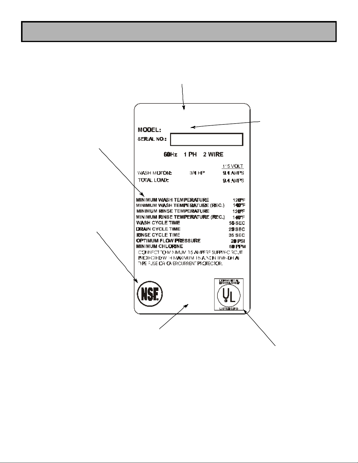
MINIMUM PARAMETERS
(SEE NOTE #1)
DETAIL OF DATA PLATE
COMPANY LOGO
MODEL DESIGNATION
(I.E. CONSERVER 24LT)
NSF LOGO
(SEE NOTE #2)
COMPONENT
MANUFACTURER’S
ADDRESS INFORMATION
UL LOGO
(SEE NOTE #3)
2
Page 7
GENERAL
Before connecting, operating or adjusting this dishmachine, please read this manual carefully to
familiarize yourself with your unit and its proper operation.
This manual contains important operating, safety and maintenance information on your dishmachine. You must follow the instructions given in the manual to ensure that your warranty remains in
effect.
Notes Concerning the Conserver 24LT/LTF Data Plates:
1) Minimum parameters must be met in order for this dishmachine to function at its intended level of
operation and efficiency. Different machines from different manufacturers have different minimum
requirements. Follow those details found on the data plate of your machine, do not use the parameters listed on the example for this manual. If you are unsure, contact your nearest authorized
Jackson service representative. Failure to ensure that the machine meets the minimum parameters
as expressed on its individual data plate may result in sub-standard performance.
2) The NSF logo on the data plate indicates that this machine has been inspected,
reviewed, tested, and approved under the guidelines and regulations set forth by
NSF International Inc., specifically Standard 3.
COMPONENT
3) This symbol indicates that this product is Listed by Underwriter’s Laboratories Inc.
Representative samples of this product have been evaluated by UL and meet the
R
applicable U.S. safety standards.
The Conserver 24LT/LTF requires that a separate chemical feeder be connected to it to provide the required sanitizer. This feeder needs to be able to provide 2.271 ml of a 10%
Chlorine sanitizer for every machine cycle.
Chemical feeder dispensing tubes are fed into the Conserver 24LT through the white bulk head fitting in the back lower portion of the unit. If the bulkhead plug is missing or damaged,
it may be ordered using part number 4730-609-05-00.
3
Page 8
INSTALLATION INSTRUCTIONS
NOTE: Before any connections are made, visually check the entire machine for any possible
shipping damage. If any damage is found, proceed to “CONCEALED DAMAGE OR MISSING
PARTS”.
UNPACKING THE DISHWASHER
STEPS: 1. Remove all protective packing material from machine.
2. Place machine in its operating location and remove skid.
CAUTION: ENSURE WEIGHT OF MACHINE IS EVENLY DISTRIBUTED
WHEN REMOVING FROM SKID INTO POSITION.
3. Adjust all four (4) adjustable bullet (or flanged) feet so contact is made to floor.
For proper operation, the dishmachine should be leveled from side to side and from front to back.
Using a level placed on the flat area at top of unit, adjust leveling feet up or down.
NOTE: The dishwasher must be positioned and leveled before making any connections to
the unit.
CONCEALED DAMAGE OR MISSING PARTS
IMPORTANT: FOR YOUR PROTECTION, PLEASE READ AND OBSERVE THE FOLLOWING:
This dishwasher has been thoroughly inspected and carefully packed before leaving our ware-
house.
Concealed loss or damage means loss or damage which does not become apparent until the dish-
washer has been unpacked. The contents may be damaged in transit due to rough handling even
though the carton may not show external damage.
If it is found that the shipment has concealed damage, PLEASE DO NOT RETURN IT TO JACK SON, but notify the carrier (within 48 hours) asking them to send their agent to fill out an inspection
report. Save the cartons so he may inspect them and be sure to note in the report any black
marks, creases, tears, crushed corners or any other marks indicating rough handling. Also, notify
the JACKSON dealer immediately.
If it is discovered that there are missing parts such as: strainers, spray assemblies, rinse assembly,
owner’s manual or racks, please notify JACKSON immediately.
4
Page 9

PLUMBING
NOTE: ALL CONNECTIONS MUST COMPLY WITH ALL APPLICABLE LOCAL, STATE AND
NATIONAL PLUMBING CODES.
The plumber is responsible for ensuring that the water line is THOROUGHLY FLUSHED BEFORE
connecting it to any manual or solenoid valve. It is necessary to remove all foreign matter such as
chips (resulting from cutting or threading pipes), pipe joint compound or, if soldered fittings are
used, bits of solder or cuttings from the lines. This debris, if not removed, may lodge in the valves
and render them inoperative.
Any valves fouled by foreign matter, and any expenses resulting from this fouling, are not
the responsibility of the manufacturer.
DRAIN LINE CONNECTION
The drain for the Conserver 24LT/LTF dishmachine is a pumped discharge. This unit comes with a
drain hose which should be connected to a system drain. It is recommended that the drain hose be
used as opposed to hard or permanent drain piping.
Ensure that the drain connection has an airgap (indirect) to allow proper draining.
The drain height should not exceed 24” above floor height.
Ensure that this unit is installed in accordance with all applicable codes.
If a grease trap is required by code, it should have a flow capacity of 5 gallons per minute.
WATER SUPPLY CONNECTION
Install the water supply line (1/2” pipe size minimum) to the dishmachine line strainer using copper
pipe. It is recommended that a water shut-off valve be installed in the water line between the main
supply and machine to allow access for service. The water supply line is to be capable of 20 PSI
“flow” pressure at a recommended temperature of 140°F (minimum of 120° F required).
In areas where the water pressure fluctuates or is greater than the recommended pressure a water
pressure regulator valve must be installed. This item should be located before the “Y”-strainer and
after the shut-off valve.
Do not confuse static pressure with flow pressure. Static pressure is the line pressure with no flow
(all valves and services are closed). Flow pressure is the pressure in the fill line when the fill valve
is open and the machine is in the fill cycle.
It is recommended a shock absorber (not supplied) be installed in the incoming water line. This
prevents line hammer (hydraulic shock), induced by the solenoid valve as it operates, from causing
damage to the equipment.
5
Page 10

ELECTRICAL
WARNING: Electrical and grounding connections must comply with applicable portions of
the National Electrical Code ANSI / NFPA 70 (latest edition) and/or other electrical codes.
WARNING: Disconnect electrical power supply and place a tag or lock at the disconnect
ELECTRICAL POWER CONNECTION
This dishmachine comes with a standard 3 prong 120V outlet power cord attached. Prior to plugging the unit into the outlet, have an electrician verify that the incoming power is at the proper voltage and to further verify L1 and N to ground individually to ensure neither is connected to a high or
“wild” leg.
Prior to installation, verify that the electrical service agrees with the specifications on the machine
data plate located on the right side and to the front of the machine. Refer to the data plate for
machine operating requirements, machine voltage, total amperage load and serial number.
VOLTAGE CONNECTIONS
STEPS:
1. Place machine’s POWER SWITCH into the off position.
2. Apply power to the dishmachine.
3. Check incoming power at power block for proper voltage per the data plate.
4. Turn off power at service breaker. Mark breaker for dishmachine and advise the
proper personnel.
DO NOT APPLY POWER OR TURN MACHINE ON AT THIS TIME. ALL PLUMBING AND
WATER CONNECTIONS MUST BE COMPLETED BEFORE MACHINE CAN BE OPERATED.
6
Page 11

CHEMICAL DISPENSING EQUIPMENT
The Conserver 24LT/LTF dishmachine is not supplied with integral chemical dispensing peri-pumps.
Instead, an independent chemical dispensing system must be connected to the unit prior to use in
order to achieve required cleanliness and sanitation. Please consult the literature that accompanied
your independent chemical dispensing system for information concerning installation and operation
of the dispenser.
The Conserver 24LT/LTF requires that a separate chemical feeder be connected to it to provide the required sanitizer. This feeder needs to be able to provide 2.271 ml of a 10%
Chlorine sanitizer for every machine cycle.
Chemical feeder dispensing tubes are fed into the Conserver 24LT through the white bulk head fitting in the back lower portion of the unit. If the bulkhead plug is missing or damaged,
it may be ordered using part number 4730-609-05-00.
WARNING: CHLORINE-BASED SANITIZERS CAN BE DETRIMENTAL TO YOUR MACHINE IF
THE CHEMICAL SOLUTION IS TOO STRONG. SEE YOUR CHEMICAL PROFESSIONAL TO
ENSURE YOUR DISPENSER IS SET UP CORRECTLY.
7
Page 12

DETERGENT CONTROL
Using detergent in the proper amount can become, in time, a source of substantial savings. In
some cases, controlling detergent use can depend on a number of variables in the warewashing
cycle. Of course, a qualified water treatment specialist can tell you what is needed for maximum
efficiency from your detergent, but you should know some basics so you’ll understand what he is
talking about.
1. The amount of detergent needed is related in one way to water hardness. Water hardness is
the amount of dissolved calcium and magnesium in the supply. The greater the amount of dis solved solids the harder the water. Hard water does not allow the detergent to act as it should
in the washing cycle, and requires more detergent to do the job. Soft water actually enhances
the effect of the detergent and you can use less to do the job and will also reduce or eliminate
scaling, a major problem with hard water.
2. It is important to understand water hardness because of the problems it causes. You may, for
instance, be adding drying agents to reduce water spotting, when the problem may be hard
water. Minerals in hard water are left on glassware and dishes after water evaporates, which
may be the cause of the water spots.
3. Remember, treated water may be an advantage for your warewashing system and a
disadvantage in other areas. For instance, coffee made with soft water may have an acid or
bitter flavor; so magnetically treat the water for your warewashing system to give better
results and use less detergent.
4. Once your water problems are solved, make sure that your dishmachine operators keep the
detergent dispenser full and in operating order at all times.
In addition to the points outlined, other factors about the detergent are important too. Certain menu
items, for instance, call for an extra-powerful detergent. Extra-hard water may require a different
type of detergent.
Also, remember that more detergent won’t do a better job of cleaning--in fact it may do worse. Too
much soap can build up just like hard water scale, so always use the recommended amount.
8
Page 13

INSTALLATION CHECKLIST
AFTER INSTALLATION, CHECK OFF THE FOLLOWING ITEMS AS THEY ARE COMPLETED
PRIOR TO PROCEEDING TO OPERATION OF DISHMACHINE.
Has dishmachine been checked for concealed damage?
Has the dishmachine been properly ventilated?
Has the dishmachine been properly leveled?
Is the drain plumbing installed to applicable codes?
Is the service voltage the same as noted on the data plate?
Has the machine been properly grounded?
Has the machine circuit breaker been sized correctly?
Has the machine circuit breaker been marked for the dishwasher?
Has the hot water supply been flushed for debris?
Is hot water supply at 12 0oF. minimum (140oF. recommended)?
Is the hot water supply flow pressure 20 P.S.I.?
Is a water pressure regulator needed?
Is the hot water supply line 1/2 inch minimum?
Have the chemical tubes been installed in the proper supply container ?
Have the peri-pumps been primed ?
Has the Sanitizing peri-pump been adjusted to inject 50 parts per million (ppm) chlorine
solution into the final rinse line ?
PROCEED TO OPERATIONAL START-UP AND CHECK
9
Page 14
OPERATING INSTRUCTIONS
PREPARING DISHES
Scrape dishes thoroughly. Pre-wash by soaking or spraying with a pre-rinse hose. Place dishes and
cups in dish rack; cups upside down. Place glasses and flatware in combination glass/flatware
rack; glasses - upside down. Scatter flatware loosely on bottom. Do not put glasses on top of flatware.
NOTE: Flatware may be washed upright in a special compartment flatware rack
for best results.
DAILY MACHINE PREPARATION
Open door and verify strainer is in wash tub sump. Check all levels in the chemical containers and
replace with full containers if empty. Check that the wash arms are installed and securely tightened.
For the initial fill, Close the door, place the Auto/Manual switch in the Auto position and turn the
power switch to the ON position. The machine will automatically fill. Allow the cycle light to turn
off. Open the door and check the water level. Close the door, the machine will now automatically
run a warm up cycle.
NOTE: Never operate wash pump without water in sump or damage to the pump
may occur.
NOTE: The correct water level should be just below the strainer.
WASHING A RACK OF DISHES
Open the door and insert a rack of soiled dishes and shut the door. The cycle will then automatically begin and cycle light will come on. When the cycle light goes out, open the doors and remove
the rack of clean dishes. Place another rack of soiled dishes in the machine and repeat the
process until all the dishware is clean.
NOTE: The unit should be drained after all dishes have been cleaned and before leaving it overnight.
DRAINING THE DISHWASHER
Open and close the door to start a cycle. Wait 5 seconds then turn the Power switch to the
OFF/DRAIN position. The machine will run a wash cycle, drain and turn off.
DAILY CLEANING OF DISHWASHER
Clean any food debris out of the wash tub strainer and clean wash arms if necessary, then replace
them into the machine. Wipe the machine down as necessary. DO NOT spray water into the
machine, it will not drain without running another OFF/DRAIN cycle.
10
Page 15

CAM TIMER OPERATION
The Conserver 24LT/LTF cam timer is a 2 minute, 8 cam timer with an OFF-DRAIN function.
The following is a description of set points for each cam and function for each switch.
CAM 1: Cam 1 is a cut cam with a single notch and serves as the Cycle/Reset.
FUNCTION: When the machine is in the operation mode the notch is the home position. The
machine will set idle until the door is opened, then cam 1 moves to the start position and holds until
the door is closed. The closing of the door will start the next cycle. The cam will rotate a complete
cycle and back to the home position and hold.
CAM 2: Cam 2 is a cut cam and provides the off/drain function.
FUNCTION: The function of the off/drain cam is controlled by the power switch. When the power
switch is in the ON position the off/drain function is disabled. To use the off/drain, start a cycle and
place the power switch in the OFF position. The machine will run a wash cycle, drain and stop. The
machine will hold this state of operation until the power switch is turned on, when turned on the
machine will fill, run a rinse cycle and stop at the home position.
The off/drain cam works off the normally open contacts of cam 2. This requires the switch to
be held closed by the cam. The off/drain cam switch will pick up just after the cycle cam switch and
drop back down just after the wash cycle cam switch.
CAM 3: Cam 3 is a cut cam and controls the wash and rinse cycles.
FUNCTION: The wash and rinse cam works off the normally open contacts of cam 3. This requires
the switch to be held closed by the cam. The wash/rinse cam switch will pick up just after the cycle
cam switch and drop back down just before the off/drain cycle cam switch. Wash pump will run
approximately 58 seconds. The machine will drain and fill. The rinse cycle will start after the fill,
approximately at the 82 second mark and will last 35 seconds. The machine will then return to the
home position.
NOTE: The last 5 cams are adjustable. The following instructions will require that the timer position
have the cams to the front and the motor to the left. (See the attached drawing)
CAM 4: Cam 4 is an adjustable cam and controls the drain valve.
FUNCTION: The drain valve cam works off the normally closed contacts of cam 4. This requires the
switch to be held open by the cam and allowed to drop into the notch to operate the drain valve.
The pumped drain and fill cams require adjustment due to varying water pressure. The drain must
be adjusted to remove whatever water the fill brings into the machine.
11
Page 16

CAM TIMER OPERATION (CONTINUED)
SETTINGS: The right side of cam 4 must be set to pick up the switch arm just before the wash
cycle cam switch drops. If the drain valve does not close first, the water in the drain hose will back
up into the pump housing and wash tank.
Any adjustment made to the drain should be made with the left side of cam 4. The adjustment must
be moved back into the wash time until all water is drained from thewash tank.
CAM 5: Cam 5 is an adjustable cam and controls the fill valve.
FUNCTION: The fill valve cam works off the normally closed contacts of cam 5. This requires the
switch to be held open by the cam and allowed to drop into the notch to operate the fill valve. The
pumped drain and fill cams require adjustment due to varying water pressure. Cam 5 must be
adjusted to fill the wash tank to the proper operating water level. (Remember, the drain cycle must
remove what the fill cycle brings in.)
SETTINGS: The left side of cam 5 must be set to drop in just past the stop point of the off/drain
cam. There must be a dwell between the off/drain and the fill, so that the fill will not run while the
machine is in the off state.
Any adjustment made to the fill should be made with the right side of cam 5. Proper water level will
be achieved when the water touches the bottom of the strainer pan.
CAM 6: Cam 6 is an adjustable cam and controls the sanitizer pump.
FUNCTION: The sanitizer pump cam works off the normally closed contacts of cam 6. This requires
the switch to be held open by the cam and allowed to drop into the notch to operate the pump.
SETTINGS: The left side of cam 6 must be set to drop in just past the starting point of the fill cam.
The adjustment for sanitizer volume must be made with the right side of the cam.
CAM 7: Cam 7 is an adjustable cam and controls the detergent pump.
FUNCTION: The detergent pump cam works off the normally closed contacts of cam 7. This
requires the switch to be held open by the cam and allowed to drop into the notch to operate the
pump.
SETTINGS: The left side of cam 7 must be set to drop in just past the starting point of the wash
cam. The adjustment for detergent volume must be made with the right side of the cam.
CAM 8: Cam 8 is an adjustable cam and controls the rinse aid pump.
FUNCTION: The rinse aid pump cam works off the normally closed contacts of cam 8. This requires
the switch to be held open by the cam and allowed to drop into the notch to operate the pump.
SETTINGS: The left side of cam 8 must be set to drop in just past the starting point of the fill cam.
12
Page 17

CAM TIMER DETAIL
13
Page 18

TROUBLESHOOTING SECTION
Power cord not correctly connected at
Ensure striker plate is activating door
machine is hooked up and all service
WARNING: Inspection, testing and repair of electrical equipment should only be performed
by a qualified service technician. Many of the tests require that the unit have power to it
and live electrical components be exposed. USE EXTREME CAUTION WHEN TESTING THE
MACHINE.
Symptom
Nothing on machine operates. Power
switch is on, power light is off.
Machine will not fill. Power switch is
on, power light is on, rinse/fill light is
off.
Possible Cause Action
Circuit breaker tripped. Reset circuit breaker. If the breaker
trips again, contact an electrican
immediately to verify machine amp
draw and breaker size.
Machine not plugged into wall
receptacle.
the termonal board.
Door not completely closed. Close door.
Faulty cam timer/cam timer
microswitch.
Plug machine in.
Verify and correct as required.
Ensure that timer is wired correctly
and that it is receiving power. If timer
is moving, replace fill microswitch.
Machine will not fill. Power switch is
on, power light is on, rinse/fill light is
on.
Faulty door switch.
switch. Check switch wiring. If all is
correct, replace door switch.
No incoming water. Ensure that incoming water to
valves are open. Ensure water is at
20 PSI flow pressure.
Faulty rinse solenoid valve. Check wiring of solenoid valve. If
correct replace coil or valve as
situation warrants.
Obstruction in incoming water line. Remove obstruction.
14
Page 19

TROUBLESHOOTING SECTION
Verify that incoming water pressure is
Verify that incoming water pressure is
WARNING: Inspection, testing and repair of electrical equipment should only be performed
by a qualified service technician. Many of the tests require that the unit have power to it
and live electrical components be exposed. USE EXTREME CAUTION WHEN TESTING THE
MACHINE.
Symptom
Wash temperature lower than
expected.
Machine fills slowly (rinse is weak).
Possible Cause Action
Low incoming water temperature. Verify that incoming water
temperature is as indicated on the
machine data plate. If not, adjust as
required.
Defective temperature guage. Replace guage.
Faulty rinse solenoid valve. Verify that the rinse solenoid valve is
working. If not, repair or replace as
required.
Low incoming water pressure.
20 PSI. If not, adjust as required.
Clogged/obstructed rinse tube plate. Verify that component is free of all
debris and soil.
Machine fills excesively.
Clogged/obstructed incoming water
line.
Faulty rinse solenoid valve. Check wiring of solenoid valve. If
Fill cam misadjusted. Adjust fill cam to ensure proper water
Incoming water pressure too high.
Remove obstruction.
correct replace coil or valve as
situation warrants.
level.
20 PSI. If not, adjust as required.
15
Page 20

TROUBLESHOOTING SECTION
Verify that incoming water pressure is
Verify that incoming water pressure is
Contact your chemical representative
WARNING: Inspection, testing and repair of electrical equipment should only be performed
by a qualified service technician. Many of the tests require that the unit have power to it
and live electrical components be exposed. USE EXTREME CAUTION WHEN TESTING THE
MACHINE.
Symptom
Wash tank water level is too low.
Dishes are not coming clean.
Possible Cause Action
Low incoming water pressure.
20 PSI. If not, adjust as required.
Fill cam timer misadjusted/faulty. Verify that timer is operating and that
the fill cam is set properly. Verify that
fill microswitch works. Replace any
defective components.
Drain valve leaking. Remove drain hose to verify valve is
not obstructed. If valve is clear, but
does not seat properly, replace.
Low incoming water pressure.
20 PSI. If not, adjust as required.
Clogged/obstructed rinse tube plate. Verify that component is free of all
debris and soil.
Door drops hard and will not stay
closed.
Chemicals are not being provided in
correct concentrations.
Broken door spring. Replace broken/defective part.
Door hinge bent. Replace defective part.
Door hinge bent. Verify that there are no obstructions
to verify chemical concentrations and
dispenser operation.
in the door channel. If there are,
remove immediately.
16
Page 21

TROUBLESHOOTING SECTION
Verify that water pressure is 20 PSI.
require the installation of an external
WARNING: Inspection, testing and repair of electrical equipment should only be performed
by a qualified service technician. Many of the tests require that the unit have power to it
and live electrical components be exposed. USE EXTREME CAUTION WHEN TESTING THE
MACHINE.
Symptom
Water flooding from the machine.
Water drains from machine at
beginning of cycle.
Possible Cause Action
Drain valve not operating. Verify wiring of valve motor. If
correct, replace the valve.
High incoming water pressure.
If not, adjust as required. This may
pressure regulating device.
Timer motor shorted out during
fill/rinse cycle; defective
microswitch.
Drain valve stuck in the open
position.
Drain valve not installed correctly,
water leaking by connections.
Verify that the timer operates and
that it and the fill microswitch are
wired correctly. If either component
is defective, replace.
Remove valve assembly; correct or
replace valve.
Correct by tightening connections.
Water leaks from the vacuum
breaker.
Damaged drain valve. Replace drain valve.
Vacuum breaker plunger or seat
deformed.
Lime or scale build-up in the
vacuum breaker.
Obstruction preventing vacuum
breaker from properly seating.
Repair using parts from vacuum
breaker repair kit.
Open vacuum breaker and remove
the plunger and seat. Use a
deliming solution to dissolve the
lime and scale. Reassemble.
Remove obstruction.
17
Page 22

CONSERVER 24LT/LTF DIMENSIONS
Legend:
A.- Drain Connection flexible hose.
6’-0” free length, 1” ID x 1 3/8 OD
B.- Electrical Connection.
C.- Water Inlet-1/2” Female Pipe Thread,
2 1/2” AFF
D.-Detergent Feeder Connection
Note: All dimensions from floor can be increased 1”
with adjustable feet supplied.
Dimensions:
Height (minimum) 33 1/4”
Height (maximum) 34 1/4”
Width 24 1/4”
Depth 22 5/8”
Inside Clearance Height 14 1/2”
Inside Clearance Width 20 1/4”
Inside Clearance Depth 21 1/4”
Door Open Depth 39 1/2”
Wall Clearance (minimum) 2 1/2”
18
Page 23

MAIN ASSEMBLY
11Kickplate Weldment
5700-011-39-43
41Top Panel
5700-041-38-38
61Door Assembly
5700-011-39-15
ITEM QTY DESCRIPTION P/N
2 12 Screw, 10-32 x 1/2" Phillips Truss Head 5305-011-39-36
3 1 Front Shroud Weldment 5700-031-38-15
5 1 Decal, Operating Instructions 9905-021-73-60
4
5
6
1
2
3
19
Page 24

MAIN ASSEMBLY (CONTINUED)
71Locknut, 1/4"-20 with Nylon Insert
5310-374-01-00
101Right Frame Weldment
5700-031-35-57
8Nuts, Keps 5/16"-18 Serrated
5310-955-01-00
ITEM QTY DESCRIPTION P/N
8 1 Back Panel 5700-031-44-33
9 4 Leg, Swivel 5340-108-02-00
11 1 Left Frame Weldment 5700-031-35-58
7
11
8
9
10
20
Page 25

CONTROL PANEL ASSEMBLY
51Delime Switch
5930-301-49-00
*94Nut, Wing, Nylon, 1/4"-20
5310-994-01-00
1
WASH/RINSE
3
OFF/DRAIN MAN.WASH
POWER ON AUTO CYCLE
POWER CYCLE RINSE/FILL
4
5
OFF
2
* - ITEM 9 NOT SHOWN
6
7
8
ITEM QTY DESCRIPTION P/N
1 1 Control Panel, C-24LT 9330-041-73-89
2 1 Wash Thermometer 6685-111-40-38
3 1 Decal, Control Panel, C-24LT 9905-031-73-92
4 1 Switch, ON/FILL & OFF/DRAIN 5930-011-49-55
6 1 Light, Red 5945-111-44-45
7 1 Light, Amber 5945-111-44-44
8 1 Light, Green 5945-111-44-43
21
Page 26

ELECTRICAL PANEL ASSEMBLY
61Contactor, Motor
5945-109-05-69
91Terminal Block Spacer
5700-011-40-05
14, 15
13
12
3
1
2
4
10
6
5
9
7
11 - NOT VISIBLE
ITEM QTY DESCRIPTION P/N
1 1 Bushing, Snap 5975-210-03-00
2 1 Decal, Copper Conductors Only 9905-011-47-35
3 1 Decal, Ground-L1-L2 9905-011-40-82
4 1 Timer, 2 Minute, 8 Cam 5945-121-49-56
5 1 Decal, Timer Operation 9905-011-58-06
7 1 Locknut, 6-32 with Nylon Insert 5310-373-03-00
8 1 Terminal Block 5940-500-09-61
10 1 Electric Panel Component Weldment 5700-002-12-10
11 2 Screw, 6-32 x 5/8" Long 5305-011-39-85
12 4 Screw, 10-32 x 3/8" Long 5305-173-12-00
13 1 Wire (Ground) Lug 5940-200-76-00
14 1 Screw, 10-32 x 1/2" Long 5305-011-39-36
15 1 Starwasher, 10-24 5311-273-02-00
22
8
Page 27

KICKPLATE ASSEMBLY
34Nut, Wing, Nylon, 1/4"-20
5310-994-01-00
61Schematic Decal
9905-031-74-04
3
1
4
2
* - INDICATES THAT ITEM
IS NOT SHOWN.
ITEM QTY DESCRIPTION P/N
1 1 Kickplate Weldment 5700-011-39-43
2 1 Control Panel Assembly 5700-002-15-90
Control Panel Only 9330-041-73-89
4 1 Dielectric Cover 5700-011-40-49
5 1 Decal, Power Disconnect Warning 9905-021-47-07
23
Page 28

INCOMING PLUMBING ASSEMBLY
63Fitting, 1/2" Male
4730-011-59-53
7
6
9
2
6
11
3
5
1
8
10
6
12
3
3
4
ITEM QTY DESCRIPTION P/N
1 1 Inlet Strainer 4730-217-01-10
2 1 Solenoid Valve 4810-100-12-18
3 3 Elbow, 90 Deg., 1.2" M Slip x 1/2" F Slip 4730-406-31-01
4 1 Tube, Copper, 1/2" x 4 1/2" Long 5700-011-59-83
5 1 Tube, Copper, 1/2" x 19 1/2" Long 5700-011-59-84
7 1 Fitting, Tee, 1/2" x 1/2" x 1/4" 4730-411-25-01
8 1 Union, 1/2" Copper to Copper 4730-412-05-01
9 1 Gauge, Pressure 6685-111-59-66
10 1 Tube, Copper, 1/2" x 25 1/2" Long 5700-011-59-85
11 1 Tube, Copper, 1/2" x 2" Long 5700-011-59-86
12 1 Ball Valve, Test Cock 4810-011-72-67
24
Page 29

SOLENOID VALVE REPAIR KITS (1/2”, 110V)
31Coil Cover
4810-200-01-18
ITEM QTY DESCRIPTION P/N
1 1 Screw N/A
2 1 Data Plate N/A
4 1 Coil, 110 Volt 4810-200-01-18
5 1 Valve Bonnet N/A
6 1 Plunger 4810-200-04-18
7 1 Spring 4810-200-04-18
8 1 O-Ring 4810-100-10-18
9 1 Diaphragm Retainer N/A
10 1 1/2" Diaphragm 4810-100-03-18
11 1 Valve Body N/A
1
2
4
5
6
7
8
3
9
10
11
25
Page 30

VACUUM BREAKER ASSEMBLY
21Nipple, Drain
5700-011-40-74
41Adapter, Male (CU to MSPS)
4730-401-03-01
YOU MAY ORDER THE VACUUM BREAKER (ITEM
3) REPAIR KIT USING P/N 4820-001-60-56.
3
4
1
POINT OF CONNECTION WITH
THE INCOMING PLUMBING
ASSEMBLY.
2
ITEM QTY DESCRIPTION P/N
1 1 Elbow, 90 Degree, Brass, Street, 1/2" NPT 4730-206-08-00
3 1 Vacuum Breaker, 1/2" NPT 4820-300-07-00
26
Page 31

WASH ARM ASSEMBLY
11Wash Arm Weldment
5700-021-46-58
31End Plug, Wash Arm
5700-021-39-23
1
3
2
ITEM QTY DESCRIPTION P/N
2 1 Bearing Assembly 5700-021-35-97
27
Page 32

WASH MANIFOLD ASSEMBLY
32O-Ring
5330-111-35-15
71Nut, Brass
5700-000-86-23
3
1
2
4
5
3
7
6
ITEM QTY DESCRIPTION P/N
1 1 Screw, with Rubber Washer, 1/4"-20 5305-974-01-00
2 1 Casting, Upper Wash Manifold 5700-021-52-81
4 1 Tube, Manifold, Conserver 24LT 5700-002-13-75
5 1 Casting, Lower Wash Manifold 5700-021-52-80
6 1 Gasket, Lower Wash Manifold Casting 5330-200-23-00
28
Page 33

DRAIN PLUMBING ASSEMBLY
52Bolt, 1/4"-20 x 1/2" Long
5305-274-02-00
1
3
6
4
2
1
5
1
7
DRAIN VALVE ASSEMBLY
LOCATION. SEE PAGE
ENTITLED “DRAIN VALVE
ASSEMBLY” FOR DETAIL.
7
* - INDICATES THAT ITEM IS NOT SHOWN.
ITEM QTY DESCRIPTION P/N
1 3 Hose Clamp, HS 16 4730-719-06-00
2 1 Hose, Drain, Formed 4720-121-40-36
3 2 Locknut, 1/4"-20 with Nylon Insert 5310-374-01-00
4 1 Valve Bracket 5700-021-36-15
6 2 Locknut, 10-32, with Nylon Insert 5310-373-02-00
7 1 Hose, 10 Ft Long 5700-111-39-72
*8 1 Power Cord, 125V, 96" Long 6145-309-04-00
29
Page 34

DRAIN VALVE ASSEMBLY
311" Hosebarb, 90 Deg. X 3/4" NPT
4730-011-65-87
61Motor Mounting Plate Weldment
5700-031-96-02
91Grommet, Heyco
5975-210-03-00
17
19
18
SERVICE RETROFIT KIT FOR
REPLACING THE “DEPENDOVALVE” WITH MOUNTING
15
14
11
BRACKETS AND COVER
PLATE CAN BE ORDERED
USING P/N 6401-031-66-40.
10
8
7
6
4
2
13
12
5
ORDER THIS ENTIRE ASSEMBLY
USING P/N 5700-031-66-26.
9
3
16
ITEM QTY DESCRIPTION P/N
1 1 Ball Valve 5700-011-66-57
2 1 1" Hosebarb, Straight x 3/4" NPT 4730-011-65-86
4 1 Bracket, Support, Round 5700-021-93-91
5 1 Bracket, Support, Oct. 5700-021-93-94
7 4 Tric-Nut, 10-32 AK Fastener, S/S 5340-111-58-10
1
8 1 #10 External Tooth Washer 5311-273-02-00
30
Page 35

DRAIN VALVE ASSEMBLY (CONTINUED)
101Cam Weldment
5700-011-65-78
171Valve Cover
5700-031-65-70
191Warning Decal
9905-100-75-93
11 1 Dielectric Plate 5700-011-65-80
12 1 Micro Switch 5930-011-65-81
13 2 4-40 x 5/8" Round Head, PH, S/S 5305-011-49-70
14 1 Motor, 14 RPM, 115V with Mounting Screws 4320-111-35-13
15 1 Ground Terminal 5940-011-75-70
16 4 Hex Nut, 10-32 UNF 5310-373-02-00
18 4 10-32 x 3/8" Truss Head PH, S/S 5305-173-12-00
31
Page 36

WASH MOTOR TO WASH TUB ASSEMBLY
31Hex Nut
5700-000-86-23
116Locknut, 1/4"-20 with Nylon Insert
5310-374-01-00
1
2
3
5
6
11 - NOT SHOWN
4
4
8
9
10
4
7
4
ITEM QTY DESCRIPTION P/N
1 1 Discharge Hub 5700-021-37-90
2 1 Gasket 5330-200-23-00
4 4 Clamp, Worm 4730-719-06-09
5 1 Hose, 1-1/4" ID 5700-111-40-46
6 1 Wash Motor/Pump 6105-131-50-93
7 1 Hose, 1-1/2" ID 5700-011-22-92
8 1 Gasket, Suction Adapter 5330-021-40-87
9 1 Suction Adapter 9515-031-39-86
10 6 1/4" Flatwasher 5311-174-01-00
32
Page 37

WASH MOTOR ASSEMBLY
31Mechanical Seal
5330-011-44-06
3
2
1
4
5
ITEM QTY DESCRIPTION MFG. NO.
1 1 Wash Pump Impeller 4320-021-44-02
2 1 Wash Pump Gasket 5330-011-44-08
4 1 Motor Only 6105-021-44-03
5 1 Pump Casing Only 5930-021-44-07
6 1 Wash Motor and Pump Assembly, Complete 6105-131-50-93
33
Page 38

14
51Spray Baffle
5700-031-37-56
131Inner Door
5700-031-32-85
161Striker, Door Switch
5700-011-44-24
192Locknut, 10-32, with Nylon Insert
5310-373-02-00
15
DOOR ASSEMBLY
ORDER THIS ENTIRE ASSEMBLY
USING P/N 5700-011-39-15.
2
11
6
5
8
13
ITEM QTY DESCRIPTION P/N
1 1 Door Handle, S/S 5340-011-60-25
2 1 Seal Channel, Inner Door, Left 5700-031-32-89
3 1 Outer Door Weldment 5700-021-35-72
4 1 Right Hinge Assembly Weldment 5700-021-38-75
12
19
18
1
10
16
7
9
3
17
4
6 1 Left Hinge Assembly Weldment 5700-021-38-76
7 2 Spacer, Hinge UHMW 5700-011-44-23
8 6 Fastener, Screw, 1/4"-20 x 1-1/2" Lg. 5305-011-44-50
9 2 Hinge Retaining Plate Assembly 5700-011-44-37
10 1 Baffle, Door 5700-001-44-75
11 1 Seal Channel, Inner Door, Right 5700-031-32-91
12 1 Latch Assembly 5700-011-44-41
14 1 Seal Channel, Inner Door, Top 5700-031-32-90
15 12 Fastener, Screw, 10-32 Counter Sink, 1/2" Lg. 5305-011-44-51
17 2 Fastener, Screw 10-32 x 1/2" Lg. 5305-011-44-52
18 12 10-32 Fastener, S/S 5340-111-58-10
34
Page 39

MISCELLANEOUS DOOR SUB-ASSEMBLIES
11Plate, Hinge Retaining
5700-011-44-25
231/4"-20 Monel Inserts
5340-011-76-67
11Latch, Door, Casting
5700-011-44-40
21Spring, Latch
5700-011-44-39
32Roller, Latch
5700-011-44-38
1
HINGE RETAINING PLATE ASSY
P/N 5700-011-44-37
2
2
ITEM QTY DESCRIPTION P/N
DOOR LATCH ASSEMBLY
P/N 5700-011-44-41
3
1
ITEM QTY DESCRIPTION P/N
DOOR SPRING
2 PER UNIT
P/N: 5340-011-44-58
35
Page 40

CONSERVER 24 LTF OPTION SIDE PANELS
RIGHT DRESS PANEL
CONSERVER-24LTF OPTION ONLY
1 PER UNIT
P/N 5700-041-38-08
LEFT DRESS PANEL
CONSERVER-24LTF OPTION ONLY
1 PER UNIT
P/N 5700-041-38-37
36
Page 41

MISCELLANEOUS RINSE PLUMBING PARTS
RINSE PLUMBING PLATE
1 PER UNIT
P/N: 5700-011-82-73
RINSE PLUMBING PLATE WITH TUBE
1 PER UNIT
P/N: 5700-011-82-74
VELLUMOID RINSE GASKET
2 PER UNIT
P/N: 5330-111-42-81
RINSE TUBE STIFFENER
1 PER UNIT
P/N: 5700-031-52-82
37
Page 42

RINSE ASSEMBLY HOSE/STRAINER WELDMENT
RINSE ASSEMBLY HOSE
1 PER UNIT
P/N: 5700-011-38-83
STRAINER WELDMENT
1 PER UNIT
P/N: 5700-031-35-81
STRAINER SPACER (NOT SHOWN)
P/N: 5700-021-35-83
38
Page 43

Conserver 24LT/LTF
ELECTRICAL DIAGRAM
115 volt - 60 hertz - single phase
39
Page 44

JACKSON MAINTENANCE & REPAIR CENTERS (USA)
ALABAMA
Jones-McLeod Appliance
1616 7th Avenue North
Birmingham, AL 35203
(205) 251-0159
(800) 821-1150
(205) 322-1440 fax
Jones-McLeod Appliance
854 Lakeside Drive
Mobile, AL 36693
(334) 666-7278
(800) 237-9859
(334) 661-0223 fax
ALASKA
Restaurant Appliance
Service
7219 Roosevelt Way NE
Seattle, WA 98115
(206) 524-8200
(800) 433-9390
(206) 525-2890 fax
ARIZONA
GCS Service, Inc. #78
5052 South 40th Street
Phoenix, AZ 85040
(602) 474-4510
(800) 510-3497
(602) 470- 4511 fax
Authorized Commercial
Food Equipment Service
4832 South 35th St.
Phoenix, AZ 85040
(602) 234-2443
(800) 824-8875
(602) 232-5862 fax
ARKANSAS
Bromely Parts & Service
10th & Ringo
P.O. Box 1688
Little Rock, AR 72202
(501) 374-0281
(800) 482-9269
(501) 374-8352 fax
ARKANSAS (cont)
Commercial Parts &
Service
3717 Cherry Road
Memphis, TN 38118
(901) 366-4587
(800) 262-9155
(901) 366-4588 fax
CALIFORNIA
P & D Appliance
4220-C Roseville Road
North Highlands, CA 95660
(916) 974-2772
(800) 824-7219
(916) 974-2774
P & D Appliance
100 South Linden Avenue
S. San Francisco, CA 94080
(650) 635-1900
(800) 424-1414
(650) 635-1919 fax
Barkers Food
Machinery Equipment
5367 Second Street
Irwindale, CA 91706
(626) 960-9390
(800) 258-6999
(626) 337-4541 fax
GCS Service, Inc. #24
1100 East Pico Blvd
Los Angeles, CA 90021
(213) 683-2090
(800) 327-1433
(213) 683-2099 fax
GCS Service, Inc. #24
650 S. Grand Avenue
Suite 111
Santa Ana, CA 92705
(714) 542-1798
(800) 540-0719
(714) 542-4787 fax
GCS Service, Inc. #52
360 Littlefield
S. San Francisco, CA 94080
(650) 635-0720
(800) 969-4427
(650) 871-4019 fax
CALIFORNIA (cont)
GCS Service, Inc. # 84
9030 Kenamar Drive
Suite 313
San Diego, CA 92121
(858) 549-8411
(800) 422-7278
(858) 549-2323 fax
COLORADO
GCS Service, Inc. #60
10525 East 40th Ave.
Suite 206
Denver, CO 80239
(303) 371-9054
(800) 972-5314
(303) 371-4754 fax
Metro Appliance Service
1640 South Broadway
Denver, CO 80210
(303) 778-1126
(800) 525-3532
(303) 778-0268 fax
CONNECTICUT
GCS Service, Inc. #06
302 Murphy Road
Hartford, CT 06114
(860) 549-5575
(800) 423-1562
(860) 527-6355 fax
DELAWARE
Food Service Equipment
2101 Parkway South
Broomall, PA 19008
(610) 356-6900
(610) 356-2038 fax
GCS Service, Inc. #44
817 N. Third Street
P.O. Box 3564
Philadelphia, PA 19123
(215) 925-6217
(800) 441-9115
(215) 925-6208 fax
Elmer Schultz Service
36 Belmont Ave.
Wilmington, DE 19804
(302) 655-8900
(800) 225-0599
(302) 656-3673 fax
40
Page 45

JACKSON MAINTENANCE & REPAIR CENTERS (USA)
DELAWARE (cont)
EMR Service Division
106 Willamsport Circle
Salisbury, MD 21804
(410) 543-8197
(410) 543-4038 fax
FLORIDA
GCS Service, Inc. #15
3373 N. W. 168th Street
Miami, FL 33056
(305) 621-6666
(800) 766-8966
(305) 621-6656 fax
Commercial Appliance
Service
8416 Laurel Fair Circle
Building 6, Suite 114
Tampa, FL 33610
(813) 663-0313
(800) 282-4718
(813) 663-0212 fax
GCS Service, Inc. #14
3902 Corporex Park Drive
Suite 350
Tampa, FL 33619
(813) 626-6044
(800) 282-3008
(813) 621-1174
GCS Service, Inc. # 13
4305 Vineland Road
Suite G-12
Orlando, FL 32811
(407) 841-2551
(800) 338-7322
(407) 423-8425 fax
Jones-McLeod Appliance
854 Lakeside Drive
Mobile, AL 36693
(334) 666-7278
(800) 237-9859
(334) 661-0223 fax
GEORGIA
GCS Service, Inc. #16
3127Presidential Dr.
Atlanta, GA 30340
(770) 452-7322
(300) 334-3599
(770) 452-7473 fax
GEORGIA (cont)
Southeastern
Restaurant Service
2200 Norcross Pkwy,
Suite 210
Norcross, GA 30071
(770) 446-6177
(800) 235-6516
(770) 446-3157 fax
Whaley Foodservice
Repairs
109-A Owens Industrial Drive
Savannah, GA 31405
(912) 447-0827
(888) 765-0036
(912) 447-0826 fax
HAWAII
Food Equipment Parts &
Service Co.
300 Puuhale Road
Honolulu, HI 96819
(808) 847-4871
(808) 842-1560 fax
IDAHO
Ron’s Service
703 E. 44th Street, Suite 10
Garden City, ID 83714
(208) 375-4073
(208) 375-4402 fax
Restaurant Appliance
Service
7219 Roosevelt Way Ne
Seattle, WA 98115
(206) 524-8200
(800) 433-9390
(206) 525-2890 fax
ILLINOIS
GCS Service Inc. #12
696 Larch Avenue
Elmhurst, IL 60126
(630) 941-7800
(800) 942-9689
(630) 941-6048 fax
Cone’s Repair Service
2408 40th Avenue
Moline, IL 61265
(309) 797-5323
(800) 716-7070
(309) 797-3631 fax
ILLINOIS (cont)
Eichenauer Services, Inc.
130 S. Oakland Street
Decatur, IL 62522
(217) 429-4229
(800) 252-5892
(217) 429-0226 fax
GCS Service, Inc. #80
9722 Reavis Park Drive
St. Louis, MO 63123
(314) 638-7444
(800) 284-4427
(314) 638-0135 fax
INDIANA
Commercial Parts and
Service
5310 E. 25th Street
Indianapolis, IN 46218
(317) 545-9655
(800) 727-8710
(317) 549-6286 fax
IOWA
Goodwin-Tucker Group
3509 Delaware Avenue
Des Moines, IA 50313
(515) 262-9308
(800) 372-6066
(515) 262-2936 fax
Cone’s Repair Service
1056 27th Ave. SW
Cedar Rapids, IA 52404
(319) 365-3325
(800) 747-3326
(319) 365-0885 fax
KANSAS
GCS Service Inc. #82
6107 Connecticut
Kansas City, MO 64120
(816) 920-5999
(800) 229-6477
(816) 920-7387 fax
KENTUCKY
Certified Service Center
Ramco Business Park
4283 Produce Road
Louisville, Ky 40218
(502) 964-7007
(800) 637-6350
(502) 964-7202 fax
41
Page 46

JACKSON MAINTENANCE & REPAIR CENTERS (USA)
KENTUCKY (cont)
Commercial Parts &
Service
4204 South Brook Street
Louisville, KY 40214
(502) 367-1788
(800) 752-6160
(502) 367-0400 fax
Certified Service Center
1051 Goodwin Drive
Lexington, KY 40505
(606) 254-8854
(800) 432-9269
(606) 231-7781 fax
Commercial Parts &
Service
1002 Nandino Blvd.
Lexington, KY 40511
(606) 255-0746
(800) 432-9260
(606) 255-0748 fax
LOUISIANA
Bana Parts, Inc.
1501 Kueble Street
Harahan, LA 70123
(504) 734-0076
(800) 325-7543
(504) 734-8456 fax
Bana Parts, Inc.
4028 Greenwood Road
Shreveport, LA 71109
(318) 631-6550
(800) 832-6550
(318) 636-5675 fax
MAINE
GCS Service, Inc. #09
180 Second Street
Chelsea, MA 02150
(617) 889-9393
(800) 225-1155
(617) 889-1222 fax
Massachusetts Restaurant
Supply
34 South Street
Somerville, MA 02143
(617) 868-1930
(800) 338-6737
(617) 868-5331 fax
MARYLAND
GCS Service, Inc. #07
2660 Pittman Drive
Silver Spring, MD 20910
(301) 585-7550 (DC)
(410) 792-0388 (Balt)
(800) 638-7278
(301) 495-4410 fax
EMR Service Division
700 East 25th Street
Baltimore, MD 21218
(410) 467-8080
(800) 879-4994
(410) 467-4191 fax
EMR Service Division
106 Willamsport Circle
Salisbury, MD 21804
(410) 543-8197
(888) 687-8080
(410) 548-4038 fax
EMR Service Division
2626 Pittman Drive
Silver Spring, MD 20910
(301) 588-8080
(800) 348-2365
(301) 588-6985 fax
MASSACHUSETTS
GCS Service, Inc. #09
180 Second Street
Chelsea, MA 02150
(617) 889-9393
(800) 225-1155
(617) 889-1222 fax
Massachusetts Restaurant
Supply
34 South Street
Somerville, MA 02143
(617) 868-1930
(800) 338-6737
(617) 868-5331 fax
Ace Service Co.
95 Hampton Avenue
Needham, MA 02494
(781) 449-4220
(800) 225-4510 MA & NH
(781) 444-4789 fax
MASSACHUSETTS (cont)
GCS Service, Inc. #06
302 Murphy Road
Hartford, CT 06114
(860) 549-5575
(800) 723-1562
(860) 527-6355 fax
MICHIGAN
GCS Service, Inc. #20
31829 West Eight Mile Road
Livonia, MI 48152
(248) 426-9500
(800) 772-2936
(248) 426-7555 fax
Jackson Service
3980 Benstein Road
Commerce Township, MI 48382
(248) 363-4159
(800) 332-4053
(248) 363-5448 fax
MINNESOTA
Metro Commercial
Service, Inc.
2857 Louisiana Avenue N.
Minneapolis, MN 55427
(612) 546-4221
(800) 345-4221
(612) 546-4286 fax
MISSISSIPPI
Commercial Parts &
Service
5755 Gallant Drive
Jackson, MS 39206
(601) 956-7800
(800) 274-5954
(601) 956-1200 fax
Commercial Parts &
Service
3717 Cherry Road
Memphis, TN 38118
(901) 366-4587
(800) 262-9155
(901) 366-4588 fax
42
Page 47

JACKSON MAINTENANCE & REPAIR CENTERS (USA)
MISSOURI
GCS Service, Inc. #82
6107 Connecticut
Kansas City, MO 64120
(816) 920-5999
(800) 229-6477
(816)920-7387 fax
GCS Service, Inc. # 80
9722 Reavis Park Drive
St. Louis, MO 63123
(314) 638-7444
(800) 284-4427
(314) 638-0135 fax
Kammerlin Parts & Service
2728 Locust Street
St. Louis, MO 63103
(314) 535-2222
(314) 535-6205 fax
MONTANA
Restaurant Appliance
Service
7219 Roosevelt Way NE
Seattle, WA 98115
(206) 524-8200
(800) 433-9390
(206) 525-2890 fax
NEBRASKA
Goodwin-Tucker Group
815 N. 19th Street
Omaha, NE 68102
(402) 345-7400
(800) 228-0342
(402) 346-6145 fax
NEVADA
GCS Service, Inc. #77
3585 East Patrick Lane
Suite 1000
Las Vegas, NV 89102
(702) 450-3495
(800) 500-9060
(702) 450-3491 fax
Burney’s Commercial
Service
4480 Aldevaran Avenue
Las Vegas, NV 89103
(702) 736-0006
(702) 798-7531 fax
NEW HAMPSHIRE
GCS Service, Inc. #09
180 Second Street
Chelsea, MA 02150
(617) 889-9393
(800) 225-1155
(617) 889-1222 fax
Massachusetts Restaurant
Supply
34 South Street
Somerville, MA 02143
(617) 868-1930
(800) 338-6737
(617) 868-5331 fax
Ace Service Co.
95 Hampton Avenue
Needham, MA 02494
(781) 449-4220
(800) 225-4510 MA & NH
(781) 444-4789 fax
NEW JERSEY
Jackson Faspray Service
155 Sargeant Avenue
Clifton, NJ 07013
(973) 471-8000
(800) 356-6740
(973) 471-1289 fax
GCS Service, Inc. #44
817 N. Third Street
Philadelphia, PA 19123
(215) 925-6217
(800) 441-9115
(215) 925-6208 fax
Food Service Equipment
2101 Parkway South
Broomall, PA 19123
(610) 356-6900
(610) 356-2038 fax
NEW MEXICO
Stove Parts Supply Co.
2120 Solana Street
Ft. Worth, TX 76117
(817) 831-0381
(800) 433-1804
(817) 834-7754 fax
NEW YORK
GCS Service, Inc. #01
932 Grand Street
Brooklyn, NY 11211
(718) 486-5220
(800) 969-4271
(718) 486-6772 fax
Duffy’s Equipment Service
3138 Oneida Street
Sauquiot, NY 13456
(315) 737-9401
(800) 443-8339
(315) 737-7132 fax
B.E.S.T., Inc.
3003 Genesee Street
Buffalo, NY 14225
(716) 893-6464
(800) 338-5011
(716) 893-6466 fax
Appliance Installation &
Service Corp.
1336 Main Street
Buffalo, NY 14209
(716) 884-7425
(800) 722-1252
(716) 884-0410 fax
Northern Parts & Service
21 Northern Avenue
Plattsburgh, NY 12903
(518) 563-3200
(800) 634-5005
(800) 782-5424 fax
Jackson Faspray Service
155 Sargeant Avenue
Clifton, NJ 07013
(973) 471-8000
(800) 356-6740
(973) 471-1289 fax
NORTH CAROLINA
Whaley Foodservice
Repairs
8334-K Arrowridge Blvd.
Charlotte, NC 28273
(704) 529-6242
(704) 529-1558 fax
43
Page 48

JACKSON MAINTENANCE & REPAIR CENTERS (USA)
NORTH CAROLINA (cont)
Whaley Foodservice
Repairs
203-D Creek Ridge Road
Greensboro, NC 27406
(336) 333-2333
(336) 333-2533 fax
Whaley Foodservice
Repairs
335-105 Sherwee Drive
Raleigh, NC 27603
(919) 779-2266
(919) 779-2224 fax
Whaley Foodservice
Repairs
6418-101 Amsterdam Way
Wilmington, NC 28405
(910) 791-0000
(910) 791-6662 fax
NORTH DAKOTA
Metro Commercial
Service Inc.
2857 Louisiana Avenue N.
Minneapolis,MN 55427
(612) 546-4221
(800) 345-4221
(612) 546-4286 fax
OHIO
Certified Service Center
890 Redna Terrace
Cincinnati, OH 45215
(513) 772- 6600
(800) 543-2060
(513) 612-6600 fax
Commercial Parts &
Service of Columbus
1150 West Mound Street
Columbus, OH 43223
(614) 221-0057
(800) 837-8327
(614) 221-3622 fax
Electrical Appliance
Repair Service
5805 Valley Belt Road
Cleveland, OH 44131
(216) 459-8700
(800) 621-8259
(216) 459-8707 fax
OKLAHOMA
Krueger Inc.
100 NE 24th Street
Oklahoma City, OK 73105
(405) 528-8883
(800) 522-8069
(405) 528-5405 fax
Hagar Restaurant
Equipment
1229 W. Main Street
Oklahoma City, OK 73106
(405) 235-2184
(800) 445-1791
(405) 236-5592 fax
OREGON
Ron’s Service
16364 SW 72nd Ave.
Portland, OR 97224
(503) 624-0890
(800) 851-4118
(503) 684-6107 fax
PENNSYLVANIA
GCS Service, Inc. #44
817 N. Third Street
P.O. Box 3564
Philadelphia, PA 19123
(215) 925-6217
(800) 441-9115
(215) 925-6208 fax
Elmer Schultz Service
540 North 3rd Street
Philadelphia, PA 19123
(215) 627-5400
(215) 627-5408 fax
Food Service Equipment
2101 Parkway South
Broomall, PA 19008
(610) 356-6900
(610) 356-2038
A.I.S. Commercial Parts &
Service
1816 West 26th Street
Erie, PA 16508
(814) 456-3732
(800) 332-3732
(814) 452-4843 fax
PENNSYLVANIA (cont)
GCS Service, Inc. #44
4400 Lewis Road, Suite E
Harrisburg, PA 17111
(717) 564-3282
(800) 367-3225
(717) 564-9286 fax
K & D Parts & Service
1833-41 N. Cameron Street
Harrisburg, PA 17103
(717) 236-9039
(800) 932-0503
(717) 238-4367 fax
AFS-Authorized Factory
Service, Co.
940 FIrst Avenue
Coraopolis, PA 15108
(412) 262-2330
(800) 222-8767
(412) 262-2245 fax
GCS Service, Inc. #48
210 Vista park Drive
Pittsburgh, PA 15205
(412) 787-1970
(800) 738-1221
(412) 787-5005 fax
RHODE ISLAND
GCS Service, Inc. #90
1002 Waterman Ave.
E. Providence, RI 02914
(401) 434-6803
(800) 462-6012
(401) 438-9400 fax
SOUTH CAROLINA
Whaley Foodservice
Repairs
I-26 & US1
P.O. Box 4023
West Columbia, SC 29170
(803) 791-4420
(800) 877-2662
(803) 794-4630 fax
Whaley Foodservice
Repairs
748 Congaree Road
Greenville, SC 29607
(864) 234-7011
(800) 494-2539
(864) 234-6662 fax
Kontac Industries
44
Page 49

JACKSON MAINTENANCE & REPAIR CENTERS (USA)
SOUTH CAROLINA (cont)
Whaley Foodservice
Repairs
1406-C Commerce PI.
Myrtle Beach, SC 29577
(843) 626-1866
(843) 626-2632 fax
Whaley Foodservice
Repairs
4740-A Franchise St.
N. Charleston, SC 29418
(843) 760-2110
(843) 760-2255 fax
SOUTH DAKOTA
Metro Commercial
Service, Inc.
2857 Louisiana Avenue N.
Minneapolis, MN 55427
(612) 546-4221
(800) 345-4221
(612) 546-4286 fax
TENNESSEE
Commercial Parts &
Service
3717 Cherry Road
Memphis, TN 38118
(901) 366-4587
(800) 262-9155
(901) 366-4588 fax
Commercial Parts &
Service
748 Fesslers Lane
Nashville, TN 37210
(615) 244-8050
(800) 831-7174
(615) 244-8885 fax
Commercial Appliance
Service
919 8th Ave. South
Nashville, TN 37203
(615) 254-0906
(800) 476-0906
(615) 254-0919 fax
TEXAS
GCS Service, Inc. #90
2422 Arbuckle Court
Dallas, TX 75229
(972) 484-2954
(800) 422-5026
(972) 484-2531 fax
Stove Parts Supply Co.
2120 Solana Street
Ft. Worth, TX 76117
(817) 831-0381
(800) 433-1804
(817) 834-7754 fax
GCS Service, Inc. #88
8150 Westpark
Houston, TX 77063
(713) 785-9187
(800) 868-6957
(713) 785-3979 fax
Armstrong Repair Center
5750-A Royalton
Houston, TX 77081
(713) 666-7100
(800) 392-5325
(713) 661-0520 fax
Commercial Kitchen Repair
1377 N. Brasos
P.O. Box831128
San Antonio, TX 78207
(210) 735-2811
(800) 292-2120
(210) 735-7421 fax
UTAH
Lamonica’s Restaurant
Equipment Service
6182 S. Stratler Avenue
Murray, UT 84107
(801) 263-3221
(800) 527-2561
(801) 263-3229 fax
VERMONT
Authorized Appliance
Servicenter of Vermont
74 River Street
Rutland, VT 05701
(802) 775-5588
(800) 874-1080
(802) 775-9593 fax
VERMONT (cont)
Northern Parts & Service
4874 S. Catherine Street
Plattsburg, NY 12901
(518) 563-3200
(800) 634-5005
(800) 782-5424 fax
GCS Service, Inc. #09
180 Second Street
Chelsea, MA 02150
(617) 889-9393
(800) 225-1155
(617) 889-1222 fax
VIRGINIA
GCS Service, inc. #18
2421 Grenoble Road
Richmond, VA 23294
(804) 672-1700
(800) 899-5949
(804) 672-2888 fax
Daubers, Inc.
7645 Dynatech Court
Springfield, VA 22153
(703) 866-3600
(800) 554-7788
(703) 866-4071 fax
GCS Service, Inc. #18
5760 Northampton Blvd.
Suite 106
Virginia Beach, VA 23455
(757) 464-3500
(800) 476-4278
(757) 464-4106 fax
GCS Service, Inc. #07
2660 Pittman Drive
Silver Spring, MD 20910
(301) 585-7550 (DC)
(410) 792-0388 (Balt)
(800) 638-7278
(301) 495-4410 fax
WASHINGTON
Restaurant Appliance
Service
7219 Roosevelt Way NE
Seattle, WA 98115
(206) 524-8200
(800) 433-9390
(206) 525-2890
45
Page 50

JACKSON MAINTENANCE & REPAIR CENTERS (USA)
WEST VIRGINIA
AFS-Authorized Factory
Service, Inc.
Rt.-1 Box 288
S. Charleston, WV 25312
(304) 344-8225
(800) 654-4606
(304) 344-8248 fax
WISCONSIN
Appliance Service
Center, Inc.
2439 Atwood Avenue
Madison, WI 53704
(608) 246-3160
(800) 236-7440
(608) 246-2721 fax
Appliance Service
Center, Inc.
6843 W. Belloit Road
West Allis, WI 53219
(414) 543-6460
(800) 236-6460
(414) 543-6480 fax
Appliance Service
Center, Inc.
786 Morris Ave.
Green Bay, WI 54304
(920) 496-9993
(800) 236-0871
(920) 496-9927 fax
WYOMING
Metro Appliance Service
1640 South Broadway
Denver, CO 80210
(303) 778-1126
(800)525-3532
(303) 778-0268 fax
46
Page 51

JACKSON MAINTENANCE & REPAIR CENTERS (CANADA)
6504 South Broadway
Edmonton, AB T6B0E7
(780) 469-4869
(800) 661-2500
(780) 465-6937 fax
Key Food Equipment
Services
#105-3728 North Fraser Way
Burnaby, BC V5J5G1
(604) 433-4484
(800) 665-2655
(604) 433-4684 fax
Choquette - CKS
2710 Lancaster Road
Unit 119
Ottawa, OT K1B4T7
(613) 739-8458
(800) 267-2515
(613) 739-3851 fax
Kontac Industries
6271-15 Dorman Road
Missisauga, OT L4V1H1
(905) 677-1580
(800) 661-2500
(905) 677-2863 fax
Choquette - CKS
900 Pierre Bertrand
Suite 220
Vanier, QU G1M3k2
(418) 681-3944
(800) 463-5506
(418) 681-3385 fax
Choquette - CKS
8487 19th Avenue
Montreal, QU H1Z4J2
(514) 722-2000
(800) 361-7681(Quebec)
(514) 722-5050 fax
Service D’Equipment de
Cuisine Entretien
893 King St. West
Sherbroke, QU J1H1R9
(819) 821-2153
(819) 821-4015 fax
A.A. Dot (Service
d’Entretien)
15 St. Alphonse
Ste. Therese, QU J731G3
(450) 435-7736
(450) 435-5249 fax
47
Page 52

IMPORTANT INFORMATION DATA SHEET
Model:
Serial No.:
Installation Date:
Service Rep. Name:
Phone No.:
Notes:
48
 Loading...