

ITV ICE MAKERS SPIKA Series, SPIKA NG 60, SPIKA NG 90, SPIKA NG 110, SPIKA NG 140 Service Manual
...
SERVICE MANUAL SPIKA
1
SERVICE MANUAL
SPIKA SERIES
ICE CUBE MAKERS - UNDERCOUNTER MODELS
SPIKA NG 60
SPIKA NG 90
SPIKA NG 110
SPIKA NG 140
ICE CUBE MAKERS - MODULAR MODELS
SPIKA MS 220
SPIKA MS 410
SPIKA MS 400/600 22”

SERVICE MANUAL SPIKA
2
HOW TO USE THIS MANUAL CORRECTLY
DESCRIPTION OF THE CONTENT
This manual has been created to provide the installation technician with information for the machine’s correct
installation and effective maintenance.
The document also contains a section that describes the cause of potential incidents as well as detailed
information for resolving them.
This manual should be stored in a safe place so it may be used to resolve matters related to the machine’s
operation throughout its service life.
RECEPTION AND INSTALLATION
The installation technician who handles the reception and installation may refer to the first part of this document
for important information on how to properly connect the machine to the mains, water mains and drainage, as
well as the conditioning factors and limitations. This manual also contains comprehensive information about
installing multiple stacked devices.
OPERATION
This document has been prepared so anyone may easily understand the machine’s operating principles and
quickly view each status. The manual also serves as a valuable guide about the menus and explains in detail each
of the messages that appear on the display in a technical annex located at the end.
SPECIFICATIONS AND ADJUSTMENTS
The manual’s user can consult technical information regarding the machine’s parameters, production ranges,
pressure switch adjustments, electrical or water consumption, and refrigerant charges.
MAINTENANCE AND CLEANING
In order for this document to serve as a comprehensive guide for the installer, a section has been included with
periodic maintenance and cleaning instructions as well as a detailed explanation of how to clean each element. It
is essential to refer to this manual in order to guarantee the machine’s optimal service life.
INCIDENT RESOLUTION
The document includes a technical support table to help users resolve common issues. It serves as a guide for
diagnosing issues and provides the most probable solutions.
QUALITY PARAMETERS AND CUSTOMER SERVICE
This machine has been manufactured according to rigorous quality standards. If any incidents arise, please
contact the company that installed the machine or the Customer Service department of the manufacturer:
P.I. Sector 13. Avda. dels Hostalers, 2
46394 Ribarroja del Turia. Valencia. Spain
0034961667639/ Hours: 8:00 a.m. to 7:00 p.m.

SERVICE MANUAL SPIKA
3
INDEX
1. INTRODUCTION .................................................................................................................................................... 5
1.1. Warning ........................................................................................................................................................ 5
1.2. Reception of the machine ............................................................................................................................ 6
2. INSTALLATION ...................................................................................................................................................... 6
2.1. Placing of the ice maker ............................................................................................................................... 6
2.2. Levelling of the ice maker ............................................................................................................................ 7
2.3. Installation of modular equipments on top of bins ..................................................................................... 7
2.4. Minimum distance to obstacles ................................................................................................................... 8
2.5. Water supply connection ............................................................................................................................. 9
2.6. Drain connection .......................................................................................................................................... 9
2.7. Electrical connection .................................................................................................................................. 10
3. PRIOR CHECKING AND START-UP ....................................................................................................................... 11
3.1. Prior checking ............................................................................................................................................. 11
3.2. Start-Up ...................................................................................................................................................... 12
4. SEQUENCE OF OPERATION UNDERCOUNTER MODELS (NG) ............................................................................. 13
5. SEQUENCE OF OPERATION -MODULAR MODELS (MS) ...................................................................................... 14
5.1. Initial Start-up ............................................................................................................................................ 15
5.2. Control Board ............................................................................................................................................. 16
5.3. Alarms ........................................................................................................................................................ 18
5.4. Safety pressure........................................................................................................................................... 18
5.5. Long operation ........................................................................................................................................... 18
5.6. Cycle timeout ............................................................................................................................................. 19
5.7. Short production cycle ............................................................................................................................... 19
5.8. Water filling timeout .................................................................................................................................. 19
5.9. Machine Stacking ....................................................................................................................................... 19
6. MAINTENANCE AND CLEANING PROCEDURES .................................................................................................. 20
6.1. Cleaning water distribution system for undercounter models (NG) ......................................................... 20
6.2. Cleaning water distribution system for modular models (MS) .................................................................. 23
6.3. Cleaning the bins (for undercounter models) ............................................................................................ 26
6.4. Cleaning the condenser ............................................................................................................................. 26
6.5. External cleaning of the machine ............................................................................................................... 27
6.6. Water leakage checking ............................................................................................................................. 27

SERVICE MANUAL SPIKA
4
7. TECHNICAL SPECIFICATIONS ............................................................................................................................... 28
7.1. Dimensions, voltaje .................................................................................................................................... 28
7.2. Production Charts ...................................................................................................................................... 34
8. USER TROUBLESHOOTING GUIDE ...................................................................................................................... 37
8.1. Undercounter models ................................................................................................................................ 37
8.2. Modular models ......................................................................................................................................... 38
9. WIRING DIAGRAMS ............................................................................................................................................ 39
9.1. SPIKA NG (undercounter models) .............................................................................................................. 39
9.2. SPIKA MS single-phase ............................................................................................................................... 40
9.3. SPIKA MS three-phase ................................................................................................................................ 41

SERVICE MANUAL SPIKA
5
1. INTRODUCTION
Thank you for purchasing a ‘Spika Series’ Ice Cube Maker by ITV. You have purchased one of the most reliable icemaking products on the market today.
Carefully read the instructions contained in this manual since they provide important information relative to
safety during installation, use, and maintenance.
1.1. Warnings
This device must be installed by a specialist technician.
Any modification necessary to the electrical installation for the perfect connection of the machine must
be carried out exclusively by professionally qualified and authorised staff.
To guarantee the efficient and correct operation of this device, it is essential to follow the manufacturer's
instructions, particularly with regard to maintenance and cleaning operations, which in most cases should
be carried out by qualified staff.
Actions by unqualified persons, apart from being dangerous, can cause serious faults. In case of a fault,
contact the distributor who sold it to you. We recommend that you always demand original spare parts.
Any use of the ice-cube-maker other than for producing ice, using drinking water, is considered
inappropriate.
Modifying or attempting to modify this device, apart from voiding the warranty, is extremely dangerous.
The machine should not be used in the open air or exposed to the rain. Connect to the drinking water
mains.
The machine should be connected using the cable supplied. It is not designed to be connected to a fixed
pipe.
Always disconnect the machine from the mains before carrying out any cleaning or maintenance work.
The electrical plug must be in an accessible place.
We recommend the use of filtration in case of low water quality.
Carry out unloading and recovery of materials or waste according to your national regulations on the
matter.
This device is not designed for use by persons (including children) with impaired physical, sensory or
mental capacities, or who lack experience or knowledge, except if they have had supervision or
instruction in the use of the device from a person responsible for their safety. Children should be
supervised to ensure that they do not play with the device.

SERVICE MANUAL SPIKA
6
1.2. Reception of the machine
Inspect the exterior of the packaging. If it is broken or damaged, complain to the haulier.
To checky whether the machine is damaged, UNPACK IT IN THE PRESENCE OF THE HAULIER and make a record on
the reception document, or on a separate document, of any damage that the machine may have suffered. Since 1
May 1998, it has complied with European regulations on the management of Packaging and Packaging Waste.
Always record the machine and model number. This number is marked in three places:
Packaging
There is an external label with the factory number.
Exterior of the machine
On the back, on a label that is identical to the front.
Name plate
Check that the installation kit is complete inside the machine. It is consists
of: ¾ gas connection, two filter joints, anchor bolts and the manual.
CAUTION: THE PACKAGING ITEMS (PLASTIC BAGS, CARDBOARD BOXES
AND WOODEN PALLETS) MUST NOT BE LEFT WITHIN REACH OF CHILDREN AS THEY ARE A POTENTIAL SOURCE
OF DANGER
2. INSTALLATION
2.1. Placing of the ice maker
This ice maker is not designed for outdoor operation. The icemaker should not be located next to ovens, grills or
other high heat producing equipment.
The SPIKA machines are designed to operate at room temperature between 5ºC (41ºF) and 43ºC (109.4ºF). There
may be some difficulties in ice slab removal under the minimum temperatures. Above the maximum
temperature, the life of the compressor is shortened and the production is substantially lower.
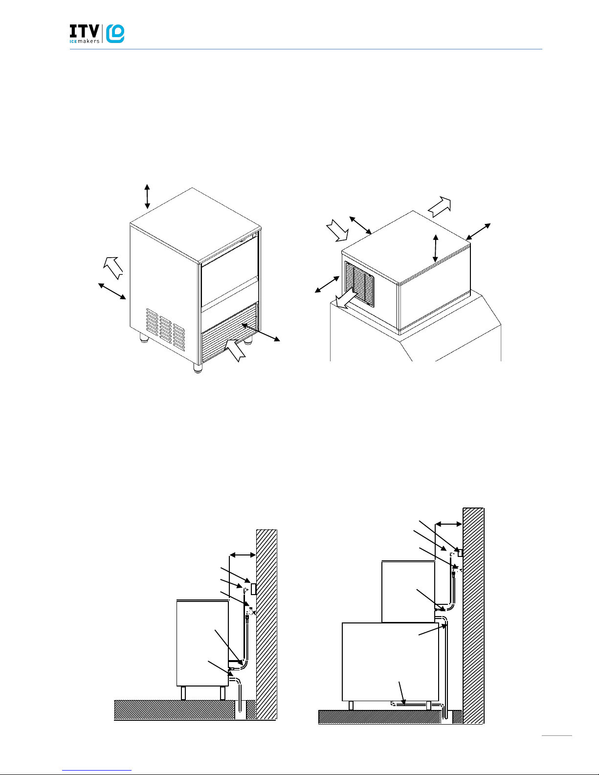
The air cooled SPIKA NG (undercounter) ice makers take the air through the front section, and drive it off through
the lateral, back and also front louvers due to their new oblique condenser structure and placement. Do not place
anything on the top of ice maker or facing the front grille. In case the front grille is either total or partially
obstructed, or due to its placement it receives hot air from another device, we recommend, in case it is not
possible to change the location, to install a water cooled machine.

SERVICE MANUAL SPIKA
7
The air cooled SPIKA MS (modular) ice makers take the air through the back section and drive it off through the
two lateral louvers. In the case it is not possible to respect the minimum distances recommended (see the picture
in point 3.3) for these machines we recommend to install a water cooled unit.
The location must allow enough clearance for water, drain and electrical connections in the rear of the ice
machine. It is important that the water inlet piping does not pass near sources of heat so as not to lose ice
production.
2.2. Levelling of the ice maker
Use a level on top of ice machine in order to ensure the equipment is perfectly leveled.
Screw the leveling legs onto the bottom of the ice machine as far as possible.
Move the machine into its final position.
Use a level on top of the ice machine. Adjust each leg as necessary to level the ice machine from front to back and
side to side.
ATTENTION: There is an optional 3 ½'' (=90mm) high casters kit that can be used in substitution of the standard
legs. These wheels are supplied with the corresponding installation instructions.
2.3. Installation of modular equipments on top of bins
Modular ice makers should be installed on top of bins, following the instructions contained in this manual.
The resistance and stability of the container-machine/s assembly should be verified as well as the fastening
elements. Follow bin manufacturer instructions.
SERVICE MANUAL SPIKA
8
2.4. Minimum distance to obstacles
Please see below the recommended minimum distances for proper operation and efficient service.
COMPACT MODELS MODULAR MODELS
CONNECTION DIAGRAM:
The location must allow enough clearance for water drain and electrical connections in the rear of the ice
machine.
UNDERCOUNTER MODELS MODULAR MODELS
FRONT
4’’(10cm)
4’’(10cm)
FRONT
6’’(15cm)
6’’(15cm)
6’’(15cm)
6’’(15cm)
29,5’’(75cm)
6’’(15cm)
Plug
Socket
Tap
Water inlet
Bin drain
Water condenser drain
(water cooled units)
Plug
Socket
Tap
Water inlet
Bin
drain
SERVICE MANUAL SPIKA
9
2.5. Water supply connection
The quality of the water supplied to the ice machine will have an impact on the time between cleanings and
ultimately on the life of the product (mainly in water cooled units). It also will have a remarkable influence on the
appearance, hardness and flavor of the ice.
Local water conditions may require treatment of the water to inhibit scale formation, improve taste and clarity. If
you are installing a water filter system, refer to the installation instructions supplied with the filter system.
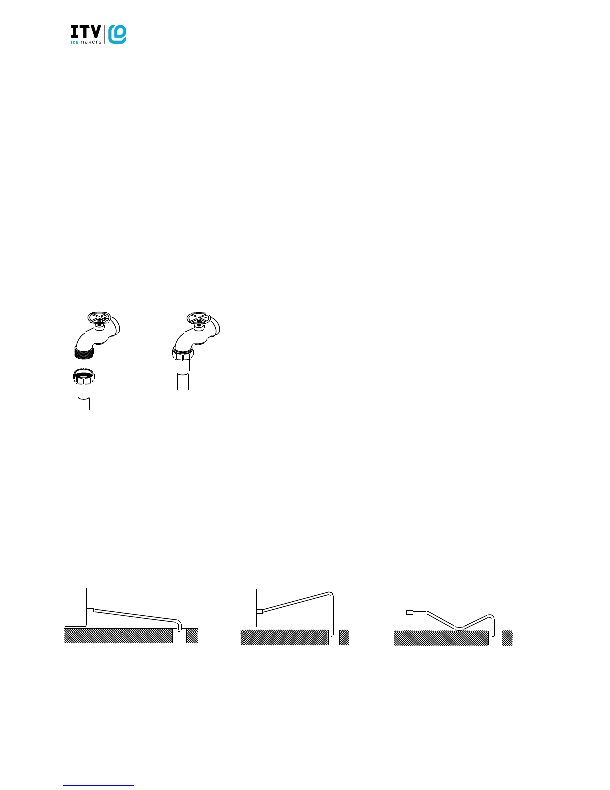
Use a flexible food grade hose.
Pressure should be between 0.7 and 6 bar (10 and 85 psi ). If pressure overpasses such values, install a pressure
regulator.
ATTENTION: The machine shall be plumbed (with adequate backflow protection) according to applicable Federal
State and local regulations.
2.6. Drain connection
Drainage should be located lower to the machine level, at 150mm (5,9”) minimum.
It is convenient that the drain hose is 30mm (1,18”) inside diameter and with a minimum gradient of 3cm/metre
(0.36’’ / ft), see figure.
Correct
Incorrect
Incorrect
SERVICE MANUAL SPIKA
10
2.7. Electrical connection
It is mandatory to ground the equipment. To avoid possible electric shock on individuals or damages to the
equipment, the machine should be grounded pursuant local and/or national regulations as the case may be.
The manufacturer shall be held harmless in case of damages arising due to the lack of the ground installation.
In case the supply cable is damaged, it should be replaced by a cable of special assembly to be furnished by the
manufacturer or after-sales service. Such replacement should be performed by qualified technical service only.
The modular units don’t have a cable with them. A qualified technical service must connect the power to the unit.
The machine should be places in such a way as to allow a minimum space between the back and the wall to allow
an easy access and without risks to the cable plug.
Safeguard the socket. It is convenient to install adequate switches and fuses.
Voltage is indicated in the nameplate and on the technical specifications section of this manual. Variation on
voltage above the 10% stated on the nameplate could result on damages or prevent the machine start-up.
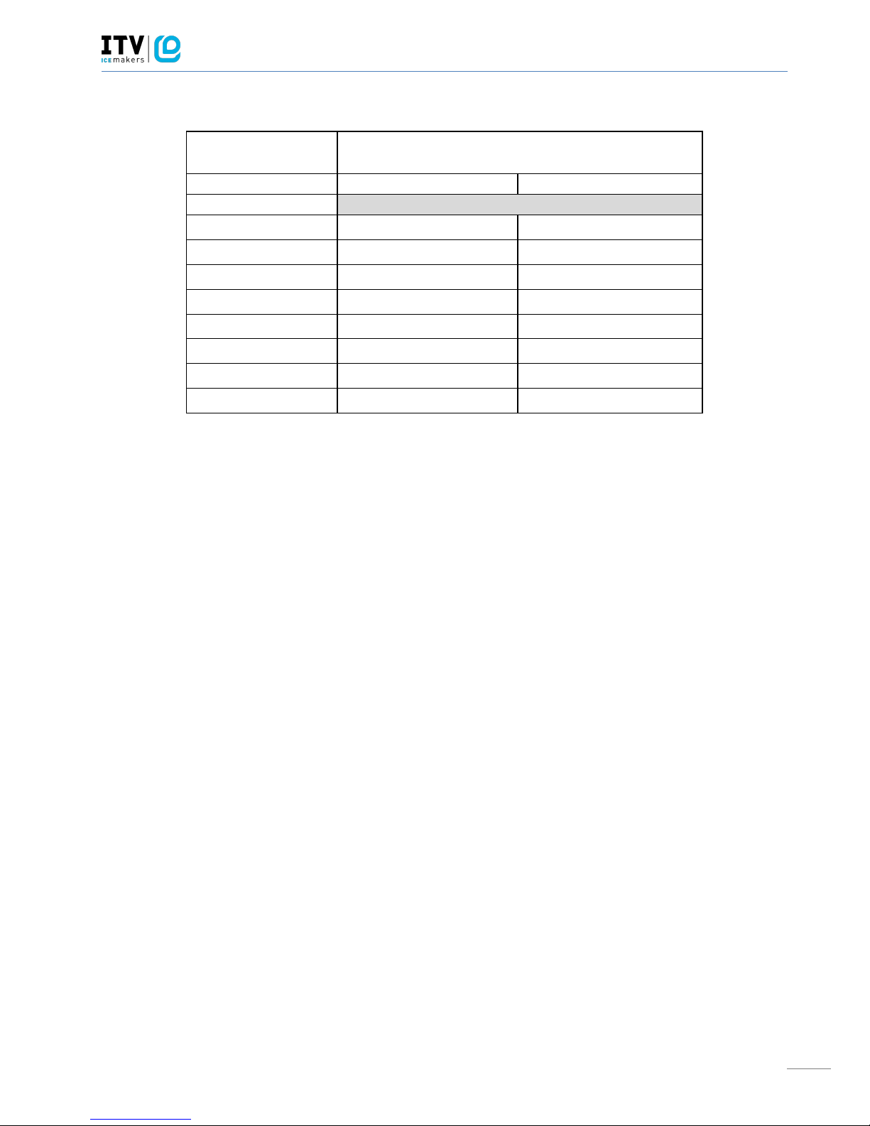
MODELOS
VOLTAGE
FRECUENCIA
FASE
AMPS
TOTAL
FUSIBLE
(A)
(A)
SPIKA NG 60
220V / 50Hz / 1F
3
16
SPIKA NG 90
220V / 50Hz / 1F
3,5
16
SPIKA NG 110
220V / 50Hz / 1F
5
16
SPIKA NG 140
220V / 50Hz / 1F
5,5
16
SPIKA MS 220
220V / 50Hz / 1F
7
16
SPIKA MS 410
380V / 50Hz / 3F
4,2
16
SPIKA MS 410
208-230V / 60Hz / 1F
5,8
16
SPIKA MS 400/600
115V / 60Hz / 1F
14.5
20
SERVICE MANUAL SPIKA
11
3. PRIOR CHECKING AND START-UP
3.1. Prior checking
Is the machine level?
Are the voltage and frequency as indicated on the plate?
Are the drains connected and do they work?
Is it connected to cold water?
** If the machine is air condensed, are the air circulation and the temperature of the premises right?
MAXIMUM
MINIMUM
AMBIENT TEMP.
43ºC
5ºC
WATER
35ºC
5ºC
Is the water pressure correct?
MINIMUM
1 Bar
MAXIMUM
6 Bar
NOTE: If the incoming water pressure is greater than 6 Bar, install a pressure reducer.
CAUTION: CHECK THAT THE VOLTAGE AND FREQUENCY OF THE MAINS ARE THE SAME AS THOSE INDICATED ON
THE NAME PLATE.
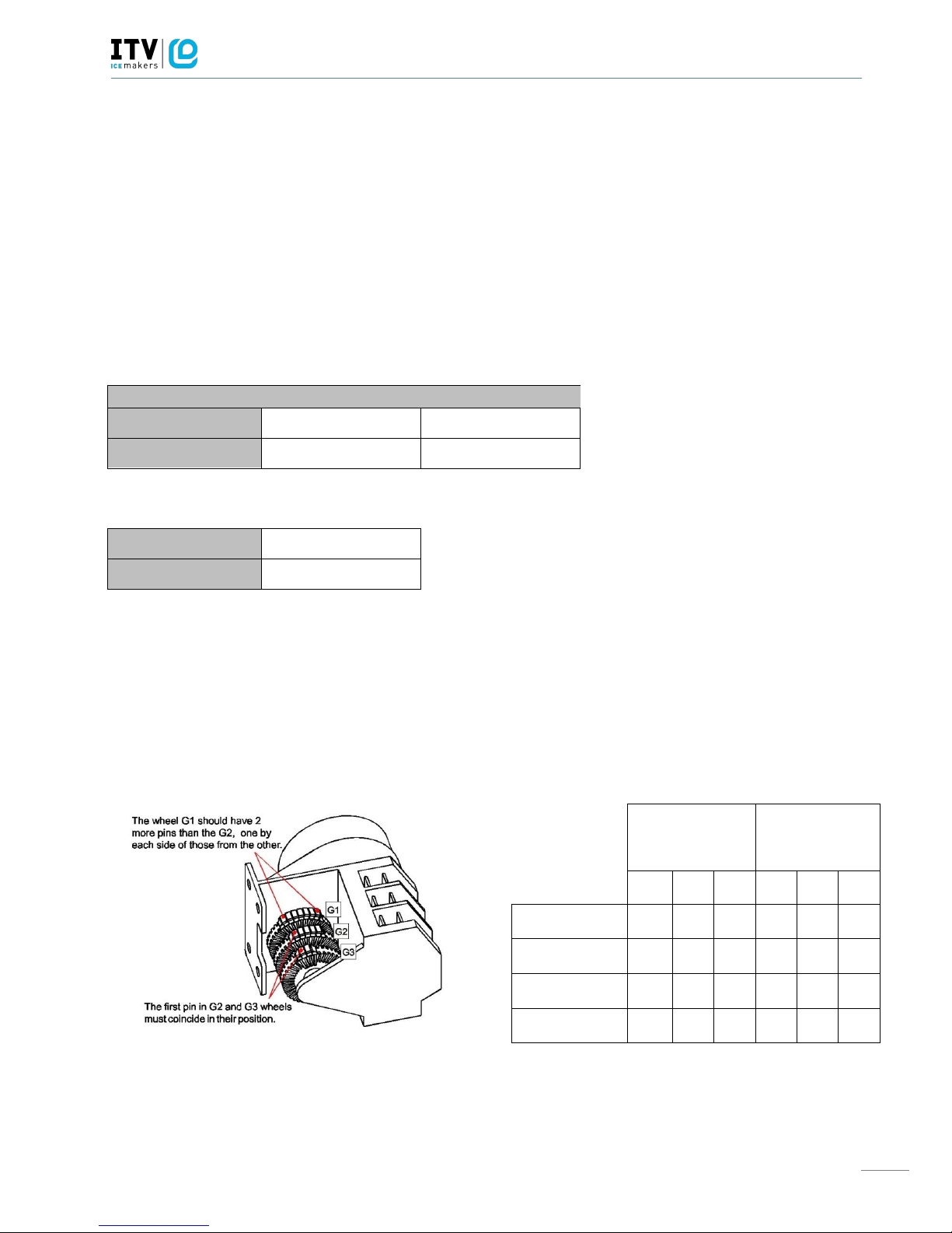
Air temp >30ºC
Water temp >20ºC
Air temp <30ºC
Water temp <20ºC
G1
G2
G3
G1
G2
G3
SPIKA NG 60
2X7
2X5
2X3
2X10
2X8
2X5
SPIKA NG 90
9 7 6
12
10
7
SPIKA NG 110
10 8 6
13
11
7
SPIKA NG 140
10 8 7
13
11
8
*indicating the number of white pins
SERVICE MANUAL SPIKA
12
REGULATION/CALIBRATION CYCLE AND STOCK THERMOSTATS
MODEL
REGULATION / CALIBRATION
CYCLE THERMOSTAT
STOCK THERMOSTAT
SPIKA
SPIKA NG 60 W1H
3,5
5,5
SPIKA NG 60 A1H
3,5
5,5
SPIKA NG 90 W1H
3,5
5,5
SPIKA NG 90 A1H
3,5
5,5
SPIKA NG 110 W1H
3
5,5
SPIKA NG 110 A1H
3
5,5
SPIKA NG 140 W1H
3
5,5
SPIKA NG 140 A1H
3
5,5
NOTE: The thermostat regulation may vary depending on the ambient temperature of water and on the place
where the machine has been installed. By default, the factory–set regulation covers a wide range of
temperatures.
3.2. Start-Up
Once the installation instructions are followed (ventilation, site conditions, temperatures, water quality, etc.),
proceed as follows:
1. Open the water inlet. Verify the no existence of leakages.
2. For undercounter models open the door and remove the protection elements on the shield. For modular
models remove the two locking screws on top of machine, take off the front panel and remove protection
elements on the shield and also on the thickness sensor.
3. Verify that the shield moves freely. For modular models verify also the thickness sensor moves freely.
4. Connect the machine to the power supply.
5. For undercounter models: push the blue switch on the machine front side. For modular models: push the
blue switch found on the back of the machine and then set the ice-wash switch to the position I.
6. Verify that there are no vibrations or frictions on the elements.
7. Verify that the water fall to the evaporator is occurring uniformly and all ice cubes are properly watered.
8. Close door (for undercounter models) / Replace the front panel in its place (for modular models).
SERVICE MANUAL SPIKA
13
9. Verify that after the final cycle, the frost on the aspiration pipe is at 20 mm (0.78 in) of the compressor.
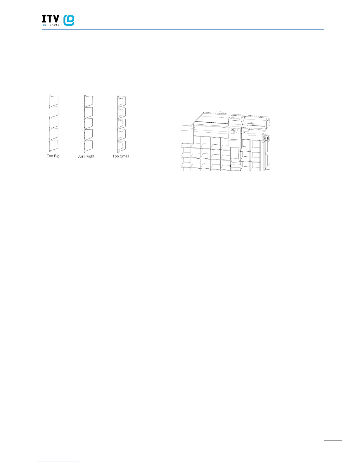
10. For modular models: Verify the ice slab with the pictures below. In case the thickness sensor needs to be
regulated, rotate the thickness adjustment screw CW to increase bridge thickness. Rotate CCW to
decrease bridge thickness. For undercounter models adjust the cycle thermostat.
Damages due to the lack of maintenance and cleaning operations are not included on the warranty.
4. SEQUENCE OF OPERATION UNDERCOUNTER MODELS (NG)
Initial Start-up: It’s recommended that the first time the machine is started (or the water tray has been emptied)
it begins with the harvest sequence to ensure the water tray is filled.
Freeze sequence: The compressor is energized. The timer G2 de-energizes the hot gas valve, so the evaporator
begins to freeze. The timer G2 energizes the water pump so the water circulates from the water tray to the upper
distributor, flowing through each cube cell, where it freezes.
Harvest sequence: The compressor will continue energized. The timer G2 energizes the hot gas valve during a
certain time. The timer G3 at the same time energizes the water inlet valve during a certain time to fill the water
tray with the appropriate quantity of water. The ice slab slides off the evaporator and into the bin. After this, the
freeze sequence starts again.
When storage bin is full the stock thermostat detects a low temperature and the machine shuts off at the end of
the freeze sequence. The ice machine remains off until enough ice has been removed from the storage bin and
the stock thermostat doesn’t detect this low temperature.
Thickness
sensor
 Loading...