


6
December 2008

NOTICE
All rights reserved. No part of this document may be changed,
reproduced or transmitted in any form or by any means (electronic,
photocopying, recording, or otherwise) without the prior written
permission of ITS Telecom.
The trademark and service marks ITS Telecom, including the ITS
Telecom mark and logo, are the exclusive property of ITS Telecom,
and may not be used without permission. All other marks
mentioned in this material are the property of their respective
owners.
Additional copies of this manual may be obtained from ITS
Telecom.
ITS Telecom reserves the right to modify the hardware and
software described in this manual without prior notice. However,
changes made to the hardware or software described does not
necessarily render this publication invalid.
WARRANTY
In the event that the product proves to be defective in
workmanship or materials within a period of one year from date of
shipment, ITS Telecom shall repair or replace the product at its
discretion. Transportation will be the responsibility of the
dealer/distributor.
Under no circumstances shall ITS Telecom be liable for
consequential or special damages, loss of revenue or
user/dealer expenses arising out of or in connection with
the use or performance of the product, whether based on
contract, tort, or any other legal agreement.
The following shall void the above warranty: malfunctions resulting
from fire, accident, neglect, abuse, or acts of God; use of improper
electrical power; or repair of, tampering with or alteration of the
product by anyone other than ITS Telecom authorized personnel.

Table of Contents
Table of Contents
Section 1: Introduction
1.1 Manual Audience and Contents...........................................................................................................1-1
1.2 Manual Conventions............................................................................................................................1-1
1.3 System Description...............................................................................................................................1-2
1.3.1 Functional Description............................................................................................................ 1-2
1.3.2 Physical Description.............................................................................................................. 1-13
1.3.3 Technical Data ..................................................................................................................... 1-14
1.4 Workflow ..........................................................................................................................................1-20
Section 2: Installation
2.1 Unpacking ...........................................................................................................................................2-1
2.2 Hardware Installation ...........................................................................................................................2-3
2.2.1 Voice Mail System Installation ................................................................................................ 2-3
2.2.2 Connections, Starting Up and Initial Indications ..................................................................... 2-5
2.2.3 Physical Expansion ................................................................................................................. 2-6
2.3 Software Setup ....................................................................................................................................2-8
2.3.1 Installing the VMS Software................................................................................................... 2-8
2.3.2 Installing the USB Driver......................................................................................................... 2-9
2.3.3 PBX Selection....................................................................................................................... 2-18
2.3.4 Configuring the VMS Toolbars............................................................................................. 2-19
2.3.5 Setting the Location of the Voice Mail System Files .............................................................. 2-20
Section 3: VMS Programming
3.1 Quick Installation Using the Installation Wizard ....................................................................................3-1
3.2 System Programming ...........................................................................................................................3-2
3.2.1 Setting the PBX Parameters.................................................................................................... 3-2
3.2.2 System Parameters................................................................................................................. 3-7
3.2.3 In-band DTMF Protocol ........................................................................................................ 3-12
3.2.4 Network Parameters ............................................................................................................ 3-15
3.3 Automated Attendant Programming..................................................................................................3-17
3.3.1 Script Programming ............................................................................................................. 3-17
3.3.2 Schedule Programming........................................................................................................ 3-26
3.4 Programming the Voice Mail..............................................................................................................3-31
3.4.1 Handling the List of Mailboxes ............................................................................................. 3-31
i

Table of Contents
3.4.2 Setting Message Notifications .............................................................................................. 3-41
3.4.3 Setting a Mailbox Group...................................................................................................... 3-45
Section 4: Administrator’s Operations
4.1 Accessing VMS Programming Data ......................................................................................................4-1
4.1.1 Setting the VMS – Voice Mail System Communication ........................................................... 4-1
4.1.2 Setting a Password................................................................................................................. 4-6
4.2 Handling Configuration Data ...............................................................................................................4-6
4.2.1 Handling Configuration Files.................................................................................................. 4-7
4.2.2 Transferring the Complete Backup Data to a Voice Mail System............................................. 4-7
4.2.3 Transferring Script Messages between Voice Mail System Units ............................................. 4-9
4.2.4 Resetting the Voice Mail System .......................................................................................... 4-10
4.3 Monitoring and Problem Solving........................................................................................................4-10
4.3.1 LCD Messages ..................................................................................................................... 4-10
4.3.2 Line Monitor ........................................................................................................................ 4-12
4.3.3 Using Statistics..................................................................................................................... 4-15
4.4 Software Upgrading...........................................................................................................................4-18
Section 5: DTMF Programming
5.1 Manual Audience and Contents...........................................................................................................5-1
5.2 DTMF Programming Rules....................................................................................................................5-1
5.3 Entering and Exiting the Programming Mode.......................................................................................5-1
5.4 Programming Commands ....................................................................................................................5-1
Section 6: Programming Forms
Section 7: VM messages
Section 8: Modem Installation
8.1 Introduction.........................................................................................................................................8-1
8.2 Basic External Modem Installation Instructions .....................................................................................8-1
8.3 Modem Installation and Configuration Process ....................................................................................8-1
8.3.1 Hardware Installation............................................................................................................. 8-2
8.3.2 Modem Software Installation ................................................................................................. 8-3
8.3.3 Modem Software Configuration ............................................................................................ 8-7
8.3.4 Settings ................................................................................................................................. 8-9
ii

Table of Contents
List of Figures
1-1 Voice Mail System Connections .......................................................................................................... 1-2
1-2 Additional Voice Mail System Connections.......................................................................................... 1-3
1-3 General View ...................................................................................................................................... 1-4
1-4 Front Panel ....................................................................................................................................... 1-13
1-5 Voice Mail System Workflow ............................................................................................................ 1-20
2-1 USB Cable Electrical Diagram .............................................................................................................. 2-2
2-2 RS-232 Cable Electrical Diagram ......................................................................................................... 2-2
2-3 Analog Ports Input Cable .................................................................................................................... 2-3
2-4 Installation of Voice Mail System in a 19” Rack................................................................................... 2-4
2-5 Installation of Voice Mail System on the Wall...................................................................................... 2-4
2-6 Expanding the Voice Mail System........................................................................................................ 2-7
2-7 VMS Main Screen ............................................................................................................................... 2-9
2-8 Found New Hardware Screen............................................................................................................ 2-10
2-9 Found New Hardware Wizard – Screen 1 .......................................................................................... 2-10
2-10 Found New Hardware Wizard – Screen 2.......................................................................................... 2-11
2-11 Found New Hardware Wizard – Screen 3.......................................................................................... 2-11
2-12 Found New Hardware Wizard – Screen 4.......................................................................................... 2-12
2-13 Found New Hardware Wizard – Screen 5.......................................................................................... 2-12
2-14 Found New Hardware Wizard – Screen 6.......................................................................................... 2-13
2-15 Found New Hardware Wizard – Screen 7.......................................................................................... 2-13
2-16 Found New Hardware Wizard – Screen 8.......................................................................................... 2-13
2-17 Found New Hardware Wizard – Screen 9.......................................................................................... 2-14
2-18 Found New Hardware Wizard – Screen 10........................................................................................ 2-14
2-19 Found New Hardware Wizard – Screen 11........................................................................................ 2-15
2-20 Found New Hardware Wizard – Screen 12........................................................................................ 2-15
2-21 Found New Hardware Wizard – Screen 13........................................................................................ 2-16
2-22 Found New Hardware Wizard – Screen 14........................................................................................ 2-16
2-23 Computer Management Screen ........................................................................................................ 2-17
2-24 USB To COM Port Selection Screen ................................................................................................... 2-17
2-25 PBX Selection List.............................................................................................................................. 2-18
2-26 Toolbar Configuration Tab ................................................................................................................ 2-19
iii

Table of Contents
2-27 File Location Tab ............................................................................................................................... 2-20
3-1 PBX Parameters Dialog........................................................................................................................ 3-3
3-2 Call Transfer Tab................................................................................................................................. 3-4
3-3 CP Tone & Disconnect Tab.................................................................................................................. 3-6
3-4 System Parameters Tab ....................................................................................................................... 3-7
3-5 Advanced Parameters Dialog .............................................................................................................. 3-8
3-6 In-Band DTMF Protocol Dialog .......................................................................................................... 3-12
3-7 In-Band DTMF Protocol Table............................................................................................................ 3-14
3-8 Network Parameters ......................................................................................................................... 3-16
3-9 Script Programming Tab.................................................................................................................... 3-18
3-10 Speech Recognition Tab.................................................................................................................... 3-21
3-11 Speech Recognition Entry.................................................................................................................. 3-22
3-12 Script Opening Tab ........................................................................................................................... 3-23
3-13 Script Status Tab ............................................................................................................................... 3-24
3-14 Dial Strings Tab................................................................................................................................. 3-25
3-15 Time, Date and Weekly Schedules Dialog.......................................................................................... 3-26
3-16 Automatic Scheduling Dialog............................................................................................................ 3-28
3-17 Auto Break Schedules Tab................................................................................................................. 3-29
3-18 Holiday Schedules Tab ...................................................................................................................... 3-30
3-19 List of Mailboxes ............................................................................................................................... 3-32
3-20 New Mailbox .................................................................................................................................... 3-33
3-21 External Notification.......................................................................................................................... 3-38
3-22 Parameters Tab for List of Mailboxes................................................................................................. 3-40
3-23 Local and External Notification Parameters........................................................................................ 3-42
3-24 E-Mail Notification Parameters .......................................................................................................... 3-44
3-25 Groups of Mailboxes Dialog.............................................................................................................. 3-45
4-1 Communication Selection ................................................................................................................... 4-2
4-2 USB Definition in Device Manager Screen ........................................................................................... 4-3
4-3 Device Selection .................................................................................................................................. 4-3
4-4 New Contact’s Details......................................................................................................................... 4-5
4-5 List of Scripts to be Read..................................................................................................................... 4-9
iv

Table of Contents
4-6 Line Monitoring Dialog ..................................................................................................................... 4-13
4-7 Typical Line Monitoring Log File........................................................................................................ 4-14
4-8 General Statistics Dialog.................................................................................................................... 4-15
4-9 Mailbox Statistics Dialog ................................................................................................................... 4-17
4-10 Script Usage Dialog........................................................................................................................... 4-17
4-11 Software Upgrading.......................................................................................................................... 4-18
8-1 External Modem Connection .............................................................................................................. 8-2
8-2 Modems Properties Screen.................................................................................................................. 8-4
8-3 Install New Modem Screen.................................................................................................................. 8-4
8-4 Modem Selection Screen..................................................................................................................... 8-5
8-5 Insert Modem Driver Location Screen.................................................................................................. 8-5
8-6 Modem Selection Screen..................................................................................................................... 8-6
8-7 COM Port Selection Screen ................................................................................................................. 8-6
8-8 Modems Properties Screen.................................................................................................................. 8-7
8-9 Specific Modem Properties Screen ...................................................................................................... 8-8
8-10 Advanced Connection Settings Screen ................................................................................................ 8-8
8-11 Connection Description Screen ........................................................................................................... 8-9
8-12 Connect To Screen.............................................................................................................................. 8-9
8-13 Modem’s Setting Properties Screen................................................................................................... 8-10
8-14 COM2 Properties Screen ................................................................................................................... 8-10
8-15 HyperTerminal Main Screen .............................................................................................................. 8-11
8-16 HyperTerminal Screen with Modem Commands ............................................................................... 8-12
v

Table of Contents
List of Tables
1-1 Voice Mail System Connections and Display...................................................................................... 1-13
2-1 Voice Mail System Packing List............................................................................................................ 2-1
4-1 Voice Mail System LCD Messages ..................................................................................................... 4-11
4-2 Line Monitor Codes and Colors......................................................................................................... 4-14
5-1 Voice Mail System Programming Cross-Reference List......................................................................... 5-2
5-2 Voice Mail System Commands for DTMF Programming....................................................................... 5-3
5-3 AA Script Commands for DTMF Programming .................................................................................... 5-3
5-4 In-band DTMF Commands for DTMF Programming............................................................................. 5-6
5-5 PBX Commands for DTMF Programming............................................................................................. 5-9
5-6 AA Scheduling Commands for DTMF Programming.......................................................................... 5-16
5-7 VM Mailbox Commands for DTMF Programming.............................................................................. 5-19
5-8 Administrator's Commands for DTMF Programming......................................................................... 5-25
5-9 VM Notification Commands for DTMF Programming ........................................................................ 5-26
6-1 Basic PBX, AA and VM Parameters Form............................................................................................. 6-1
6-2 Message Notification Form.................................................................................................................. 6-3
6-3 Time, Data and Scheduling Form ........................................................................................................ 6-4
6-4 In-band DTMF Protocol Parameters Form ............................................................................................ 6-6
7-1 VM System Messages.......................................................................................................................... 7-2
vi
Introduction
Chapter 1: Introduction
1.
1.1 Manual Audience and Contents
The Voice Mail System Installation and Programming Manual is intended for System Installers and
Administrators, responsible for the installation, setup and programming of the Voice Mail System.
Please read this manual before installation, programming
and operation.
This manual contains the following:
Chapter Heading
1 Introduction
2 Installation
3 VMS Programming
4 Administrator's Operations
5 DTMF Programming
6 Programming Forms
7 VM System Messages
8 Modem
1.2 Manual Conventions
The manual's typographic and command entry conventions are as follows:
Typeface Usage
Manual Book titles, new words or terms and words to be emphasized
Note text Heading and text of a note, caution or warning
Bold Text GUI items: dialogs, menu items, field names, etc.
1-1
Introduction
1.3 System Description
This section contains the following:
A functional description consisting of the Voice Mail System environment, functions and features
A physical description consisting of the unit's connections and indications
A technical data summary consisting of the unit's main characteristics
1.3.1 Functional Description
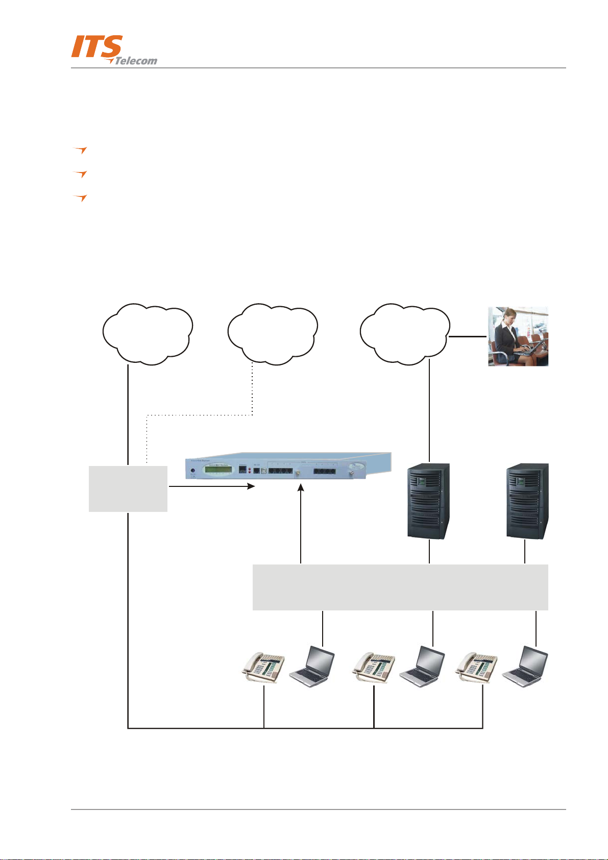
The Voice Mail System shown in Figure 1-1 and Figure 1-2 is a standalone multi-lingual Automated
Attendant/Voice Mail system for large to medium sized businesses with between 50 to 300 employees.
GSM
C.O.
Network
Internet
PBX
4/8 Analog
Ports
To A nal og
Ports Sockets
To Ethernet
Adapter
LAN
Figure 1-1: Voice Mail System Connections
LAN Server
Mail Server
1-2
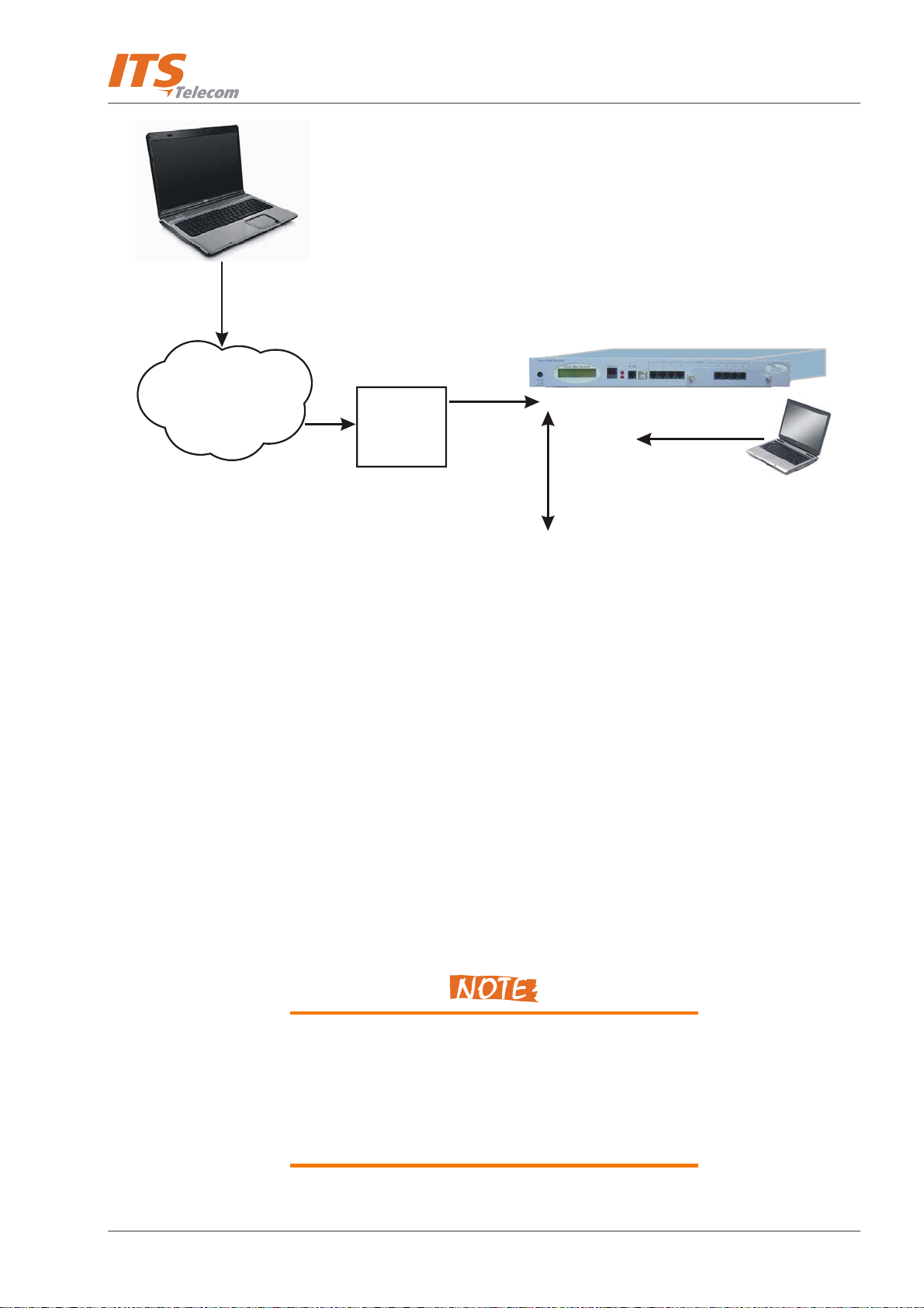
Introduction
Remote Connection
by Modem
Voice Mail System
C.O.
PBX
Figure 1-2: Additional Voice Mail System Connections
Featuring Digital Signal Processing (DSP), flash memory storage, SMT production and a real-time clock, the Voice
Mail System contains most of the Automated Attendant (AA), Voice Mail (VM) and administrative features
incorporated in PC-based systems.
The Voice Mail System is available in a 4 ports version with 72 hours of memory and is expandable to 8 ports
with 144 hours of memory. It provides up to 500 mailboxes and integrates with most PBX systems via the analog
port using In-Band DTMF protocol or by using the SMDI protocol.
The Voice Mail System can be integrated with a Local Area Network (LAN), using the LAN connection. This
feature allows the Voice Mail System to send an email notification to the voice and fax message recipients. The
new messages are sent by email in the form of attached media files. They can be played on the user’s PC
through attached desktop speakers (see note).
To 4 or 8
Analog Ports
To Ethernet
Adapter
To L AN
To USB/RS-232
Local Programming
In addition, the mailbox owner can maintain the mailbox via the LAN, using the Personal Mailbox Management
(PMM) utility.
The administrator can program and administer the Voice Mail System via a TCP/IP connection.
The Voice Mail System will be delivered with the voice
message’s e-mail notification feature enabled.
The attached media files can only be played on the user’s
PC after installation of the PMM utility and the Windows
Media Player.
1-3

Introduction
The system operates in a PBX environment, with its 4 or 8 ports connected to the analog ports of the exchange
(see Figure
connection with the PC running the Voice Mail System Voicemail Maintenance Software (VMS). It can also be
remotely programmed using a PC modem. DTMF programming is available using a touch-tone telephone
connected to one of the PBX extensions.
1-1 and Figure 1-2). The Voice Mail System is programmed locally using a direct RS-232 or USB
Figure 1-3: General View
1.3.1.1 Automated Attendant
The Automated Attendant is a menu-driven program used for transferring calls to specific departments,
extensions and mailboxes. Its main features are:
Feature Description
Opening Script Greeting The Voice Mail System plays a pre-recorded greeting to callers. The
opening greeting usually includes the organization’s name and
instructions on how to reach an extension, department or Operator,
how to switch to different languages, how to leave a message and
how to access a directory.
While the greeting is being played, the callers can access a
department by dialing a single digit, dialing an extension number or
holding on for assistance.
Number of Script Repetitions The Voice Mail System plays a pre-recorded greeting, the required
number of times, before executing an operation at the end of the
recording.
1-4

Introduction
Feature Description
Operating Modes Depending on the time and system schedule, the Voice Mail System
assumes one of four operating modes:
The day mode for normal business hours. The Voice Mail System
answers calls with a pre-recorded day greeting, prompting the
caller to enter a desired extension, mailbox, department or
directory, or to switch to a different language.
The night mode for after working hours. The Voice Mail System
answers calls with a pre-recorded night greeting that enables the
caller to leave a message in a desired mailbox.
The holiday mode. During holidays, calls are answered with a
special greeting, prompting the caller to leave a message in a
specific mailbox or in the Operator’s mailbox.
The break mode. This enables the Administrator to program a
special greeting for breaks during the day. Up to 10 breaks can
be programmed.
System Schedules (Auto-mode) If your organization’s operating hours vary from day to day, the
Administrator can define the daily operating schedules on a weekly
basis, including day, night and break time hours. When the auto-
mode is activated, the Voice Mail System automatically switches
between the day, night and break modes, according to a pre-defined
schedule.
The Operator can override the pre-defined schedule and switch
manually to the day, night, break, or holiday mode, using a password.
The Voice Mail System switches automatically to holiday mode on
dates programmed as holidays. During holidays, the Voice Mail
System answers calls with the special holiday greeting, recorded by
the administrator.
Fax Detection If the Voice Mail System detects a fax tone (CNG) during the opening
greeting, it automatically transfers the call to the pre-defined fax
extension. There are up to four fax extensions available in the Voice
Mail System.
Directory Listing (Dial By Name) The Voice Mail System enables the caller to locate a mailbox owner.
This is done by dialing the first three letters of the desired parties first
or last name. The mailbox owner programs this feature.
1-5
Feature Description
Introduction
Call Transfer
The call is transferred to an extension, in a predefined mode. The
modes can be:
Non-Supervised − the Voice Mail System transfers the call
immediately, without verifying the status of the extension.
Supervised − the Voice Mail System checks for a Busy tone or No
Answer timeout, before transferring the call to the extension.
Semi-Supervised − the Voice Mail System only checks for a Busy
signal, before transferring the call to an extension.
The Administrator can program the Voice Mail System to detect
the Call Progress tone and DTMF signals sent by the PBX.
Multilingual Option The Voice Mail System allows up to 3 languages per system. Callers
can choose the preferred language from the Automated Attendant
during the opening-greeting menu. The Administrator can select the
mailbox menu language for each mailbox owner.
Answering on the First Ring To avoid delays, the Administrator can configure each individual port
of the Voice Mail System to answer incoming calls on the first ring or
to set a number of rings for answer (up to 9).
Script Menus The Voice Mail System supports up to 98 script menus. A script menu
is a recorded announcement that can accept a digit entry (0 to 9)
while being played. Based on the digit entered, the Voice Mail System
can perform one of the following actions:
Transfer the call to another script menu
Transfer the call to another script menu and change the
language
Transfer the call to an extension or hunt group
Transfer the call to a mailbox or a mailbox group
Transfer the call to a specified Operator
Dial a DTMF string
Retrieve messages from a mailbox
Disconnect the line
Leave a message
Transfer Call to Operator Up to eight extensions can be defined as Operators and a call can be
transferred from the Script Menu or from the Personal Greeting
message to a specified Operator.
1-6

Introduction
Feature Description
Dial a String The Voice Mail System can be programmed to dial any predefined
DTMF string, while the script opening-greeting message is being
played. “Dial a String” can perform an internal PBX feature, i.e.
during the company greeting, the external subscriber is instructed to
press 7, to be able to connect to another external subscriber. “Dial a
String” will convert the digit 7 to hook flash, plus the external line
access code, plus the subscriber number and disconnect the Voice
Mail System. Up to 20 DTMF strings can be programmed.
Greeting by Port The Voice Mail System can be programmed to play an Opening
Greeting Message, when detecting an incoming call on a specified
port.
Import *.WAV file Windows media files (*.wav) can be used to create Script Opening
Greeting Messages. A source *.wav file can be transferred and
automatically converted into the required Voice Mail System format.
Speech Recognition Speech recognition as an Auto Attendant tool enables the caller to
reach the required destination by vocal pronunciation of the
destination’s extension owner name or pre-defined service words.
Auto Attendant will route the caller to the destination extension using
a list of special audio commands, which will be a part of the voice
mail system messages.
1.3.1.2 Voice Mail
The Voice Mail System receives and delivers messages using mailbox ID numbers and mailbox owners'
passwords. Messages can be saved, deleted or transferred to other mailboxes. The main features are:
Feature Description
Real/Virtual Mailboxes The Voice Mail System supports up to 500 real and virtual mailboxes. A
real mailbox is associated with an extension, whereas a virtual mailbox is
not.
Personalized Mailboxes Mailbox owners can personalize their mailboxes by recording three
personal greetings (NA, Busy and Temporary), assigning a personal
password to the mailbox and setting optional parameters.
1-7
Introduction
Feature Description
Message Waiting Notification The Voice Mail System informs a mailbox owner about recorded
messages by means of a local lamp, local ring notification or cascading
external notification to an external phone number and/or email
notification to an email address. Notification to pagers is also supported.
Some features may require special hardware in order to operate.
Mailbox Features
Personal Greetings – mailbox owners can record or change
personal greetings from any touch-tone telephone at all times.
First, callers hear the personal greeting of the called extension.
Then they can leave a message or transfer the call to an Operator,
to another extension or to an external phone number. Only the
system administrator can allow an external phone number transfer.
Greeting Selector – mailbox owners can select which message is
played to the caller.
Pause During Retrieve Messages – mailbox owners can pause the
playback of the mailbox messages for a maximum of 50 seconds.
Rewind message – pressing the
key will rewind the message by 5
*
seconds.
Fast forward message – pressing the # will fast forward the
message by 5 seconds.
Date and Time Stamp – the Administrator can program the Voice
Mail System to indicate the start of a message and the date and
time each message was recorded.
Message Deletion – messages are deleted, either manually by the
mailbox owner or automatically after a maximum number of days,
defined by the Administrator.
Call Forwarding – mailbox owners can automatically forward calls
from their personal mailbox to another mailbox. System
administrator can forward a call from the mailbox to another script.
Copy Messages – mailbox owners can copy messages to another
mailbox.
Move Messages – mailbox owners can have their messages
recorded directly into another mailbox.
Call Transfer – mailbox owners can give the caller the option to
transfer a call to operator, another extension or an external
number.
Message Reply – mailbox owners can reply to messages and record
messages in the sender’s mailbox.
Continuous Call Recording – call can be recorded for up to 20
minutes (with PBX supported).
Mailbox owner can call back to caller (with PBX supported Caller ID
information passed via In-Band DTMF).
1-8

Introduction
Feature Description
Unified Messaging A user can receive an email with or without a media attachment in his
regular email program.
Personal Mailbox Management A mailbox owner can maintain a mailbox via the local network, based
on the TCP/IP protocol, using the Personal Mailbox Management (PMM)
utility.
Mailbox Groups A caller can send a message to all the members of a mailbox group
simultaneously.
All defined mailboxes belong to the All Group mailbox group. In
addition, the Administrator can create up to four mailbox groups, each
containing up to 500 mailboxes. Mailboxes can belong to more than
one group. Mailboxes can be added or deleted from a mailbox group by
the Administrator. A mailbox group greeting can be assigned to each
mailbox group.
Do Not Disturb Mode Mailbox owners can set their mailboxes in the Do Not Disturb Mode.
When a caller dials an extension that is in the Do Not Disturb mode, via
the Automated Attendant menus, the Voice Mail System plays a special
Do Not Disturb menu and does not transfer the call to the extension.
Individual Language Selection The mailbox owner can select one of the languages supported by the
Voice Mail System. When the mailbox owner enters the mailbox, the
Voice Mail System automatically switches to the selected language.
Adjustable Recording Length The Administrator can select the length of all Voice Mail System
recorded messages. The selected length controls the following types of
messages: scripts, greetings, names and received messages.
Number of Stored Messages Each mailbox can store up to 92 messages. The Administrator controls
and can change this parameter for each mailbox. The default setting for
this parameter is 30. The Administrator can also limit the number of
days, for which messages can be stored in the mailboxes.
First Time Usage Wizard The first time mailbox owners access their mailbox, the installation
wizard automatically guides them through the setting up process.
1-9

Introduction
Feature Description
Personal FAX Mailbox owner can receive fax messages (up to 10 A-4 pages) and
retrieve them using E-mail client software or direct call to the personal
Voice Mail, where the fax message can be saved; deleted; printed on the
local company fax machine or re-sent to the external FAX machine
number.
1.3.1.3 System Administration
The Voice Mail System is equipped with many administrative functions intended to provide the Administrator
with flexible tools for fast implementation, setup and programming, as well as for long-term operations like
monitoring and maintenance. The main administrative features of the Voice Mail System are:
Feature Description
Configuration The basic Voice Mail System unit has four ports and 72 hours of
recording time.
A qualified technical person can increase the number of ports and
recording time, by adding a four-port expansion module to the basic
Voice Mail System unit.
Programming The Administrator can program the Voice Mail System using:
A computer running the Voice Mail Utility Program. In this case, it
is highly recommended to save the configuration files after each
installation.
Via a modem connection.
Via a touch-tone telephone using DTMF Codes.
Integration with Your PBX The Administrator can integrate the Voice Mail System with the PBX
using:
The in-band DTMF Protocol. This type of integration is achieved by
setting up the communication protocol of the PBX and the Voice
Mail System unit (answering a call, transferring a call, recalling as a
result of a Busy or No Answer condition, etc.).
The SMDI Integration with the RS-232 port. This type of integration
must be specifically developed for each type of PBX.
1-10
Introduction
Feature Description
Disconnection Methods Some PBXs can notify the Voice Mail System when a call is terminated
through the line interface, using Loop Disconnect, DTMF Codes or the
Busy and Disconnect Cadence. When the Voice Mail System detects this
situation, the line is disconnected and the unit is ready to receive
another call on that voice mail port.
Message Notification
The Voice Mail System automatically notifies the mailbox owner of new
messages. Notification may be local (to a PBX extension) or remote (to a
telephone at a remote location, a cellular telephone, a pager or email (to
a predefined email address). The device is able to notify a list of external
telephone numbers. The system administrator can give permission to use
the external notification to mailbox’s owners. A mailbox permitted for
external notification can transfer a call to the external number.
Call Forwarding The administrator can forward a call automatically from a personal
mailbox to another script.
Security Passwords
The Voice Mail System supports three types of 4-8 digit passwords:
Administrator (4-8 digits) for accessing all data stored in the Voice
Mail System.
Operator (4 digits) for accessing the system operating modes: Day,
Night, Holiday and Break.
Mailbox (4 digits) for accessing individual mailboxes, where the
mailbox owners can change their password at all times.
Line Monitor
This option has been enhanced with the possibility to display all
incoming and outgoing DTMF and system codes through the USB/RS-
232 cable or modem connection.
Modem Support
The Voice Mail System unit is equipped with a built in V.32 bits modem,
operating at 14.4 Kbps with a fallback rate of 9.6 Kbps. When the call is
terminated, the Voice Mail System hangs up in order to clear the port
for the next call.
Modem support can be enabled or disabled.
LCD On the front panel of the Voice Mail System the LCD display shows the
status of all 4 or 8 ports, system error messages and the current mode
of operation.
1-11
Introduction
Feature Description
Reports and Configuration Printout The Voice Mail System can provide a printout of the statistic and system
configuration reports. The statistic reports contain general information
about usage (memory, ports, mailboxes, scripts) and the configuration
reports contain information regarding the Voice Mail System
configuration.
Backup and Restore Feature The VMS creates a backup file via the local USB/RS-232 connection,
which includes the complete system configuration and recordings.
Software Upload The VMS updates the system software only via the local USB connection.
Extension Size The Voice Mail System supports flexible extension sizes between 2 to 6
digits.
Memory Re-organization
The flash memory is re-organized in a manner, similar to the de-
fragmentation process deployed for PCs hard disks. The Voice Mail
System constantly monitors the memory usage and automatically
activates the memory reorganization.
Memory Alarm When 85% of the memory has been utilized, the Voice Mail System
sends a voice alarm message to the "supervisor mailbox".
PBX Selection The Voice Mail System can be easily configured for operation with a
specific PBX. For this, use the PBX selection option in the VMS. This
option supplies a list of PBXs with default integration parameters.
Wizard An Installation Wizard is provided in the software.
1-12
Introduction
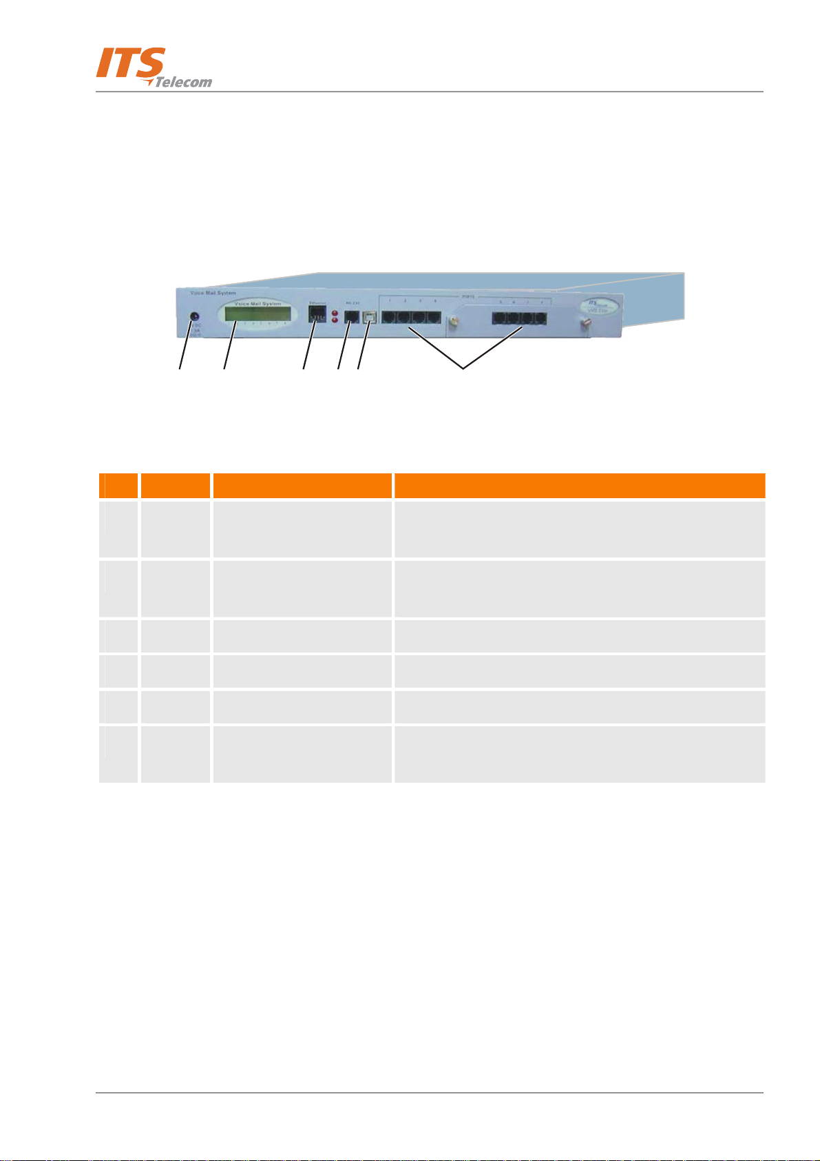
1.3.2 Physical Description
The Voice Mail System unit is built in a 422 x 43 x 165mm metal case, suitable for mounting in a standard 19"
communication rack or on a wall.
All Voice Mail System connection and display components are located on the unit's front panel, as shown in
Figure
1-4 and detailed in Table 1-1.
12
Table 1-1: Voice Mail System Connections and Display
No ID
1 9VDC
1.5A
2 - 16x2 character LCD display Displays the operational mode and populated ports of the
3 Ethernet RJ-45 socket Connects the Voice Mail System to the Local Network.
4 RS-232 RJ-11 socket Connects the Voice Mail System to a PBX, or PC.
5 USB USB socket Connects the Voice Mail System to a PBX, or PC.
6 Ports RJ-11 sockets Connects the Voice Mail System to 4 or 8 (with optional 4-
Connector Connects the Voice Mail System to an external power
3
Item Function
56
4
Figure 1-4: Front Panel
supply.
unit or a brief message in case of error.
port expansion board) PBX extensions.
1-13
1.3.3 Technical Data
The technical specification of the VME system is as follows:
General Data Description
Number of PBX extension ports 4 or 8
Extension size 2 to 6 digits (flexible)
Recording time 4 ports – 72 hours
8 ports – 144 hours
Mailboxes 500
Messages per mailbox Up to 92 (programmable)
Operator's extensions Up to 8
Fax extensions Up to 4
Introduction
Script messages Up to 98
DTMF dial strings Up to 20
In-band DTMF events Up to 40
PBX Legal extension groups Up to 10
Modem Support
Interface V.32 bis
Rates 14.4 Kbps with fallback to 9.6 Kbps
Languages
Supported languages Up to 3
1-14
Introduction
Feature Option
Automated Attendant
Opening greeting
Number of Opening Greetings repetitions
Operating modes: day, night, holiday, break, multi-break
System schedules: daily, weekly, holidays
Fax detection
Directory listing (dial by name)
Call transfer modes: non-supervised, supervised, semi-supervised
Multilingual option
Number of rings before answer
Script menus
Transfer call to specific Operator
Transfer call to extension, mailbox, group of mailboxes
Dial a string
Greeting per port
Call Screening – mailbox owners can screen incoming calls. The mailbox
owner will receive a call with the name of the caller. The mailbox owner
can decide whether he accepts the call or not.
Speech recognition (an optional feature that requires special hardware
system configuration)
1-15
Introduction
Feature
Option
Voice Mail
Real/virtual, announcer mailboxes
Personalized mailboxes
Unified messaging – email notification (this feature can be activated using
an optional hardware upgrade.)
Message waiting notification (local – lamp, ring; external – external phone
number, list of external phone numbers, pager)
Three Personal greetings
Day and time stamp
Message handling: deletion, forwarding, reply, save, automatic copy,
pause during retrieve message
Mailbox groups
Auto forward to another Mailbox or Script
Do Not Disturb mode
Transfer to another extension or external number
Adjustable recording length
Quantity of stored messages
First-time user setup wizard
Personal fax
1-16
Introduction
Feature
Option
Administration
Configuration: 4 or 8 PBX extension ports
Importing *.WAV files for Script recordings
Programming: PC or touch-tone telephone
Integration with PBX: in-band DTMF
Disconnection methods: Loop Disconnect, DTMF Disconnect, Busy
Disconnect and Disconnect tones
Security passwords: Administrator, Operator, mailbox
Line monitor: incoming/outgoing calls via USB/RS-232 port or modem
connection
Modem support: enabled/disabled
LCD: front panel monitoring
Reports: statistics and configuration print-out
Backup and restore: system configuration and recordings
Software upgrade: via USB/RS-232 port
Memory re-organization
Memory Alarm: when 85% utilized
Define mailbox owner’s permission for external notification and unified
messaging
Wizard for first time programming
RS-232, USB, modem and LAN (TCP/IP) connection
Auto-Attendant script usage report
1-17
Introduction
Feature
Option
Electrical Characteristics
DC Power Supply
Line Voltage
DC Leakage Current
On-hook Insulation Resistance between Line Terminal
and Ground
Ring Capacitor
On-hook Impedance
Ring Detect
DC Resistance (off-hook)
9VDC/1.5 A
24 to 72VDC
10µA maximum
0 to 100VDC, 5MΩ minimum
100 to 200VDC, 30KΩ minimum
500 VAC/50Hz, 20KΩ minimum
100 VAC/25Hz, 100KΩ minimum
0.47µF ± 10%
@ 50VDC, 40 VAC/25Hz, 3000Ω minimum
27 to 100VAC/16 to 60Hz
24 to 66VDC @ 20 to 100mA, 100 to 350Ω
Impedance (off-hook)
Imbalance Ratio
Return Loss
Current during Break
DTMF Transmission:
Frequency Tolerance
Frequency Level (High Group) Frequency Level (Low
Group)
Inter-digit Pause in Tone Dialing
Fax CNG Tone Detection
TCP port number for the VMS connection
TCP port number for the PMM connection
300 to 3400Hz, 500 to 700Ω
300 to 3400Hz, 46dB minimum
300 to 3400Hz, < 18dB
700µA, maximum
+1.5%
-6 to -8dBm
-8 to -10dBm
70 to 80ms
1100Hz ± 38Hz
10253
10252
1-18

Introduction
Feature
Option
Mechanical Characteristics
Dimensions (W x H x D)
Weight
422 x 43 x 165 mm
2.2 Kg
1-19

Introduction
1.4 Workflow
Figure 1-5 provides the workflow for the Voice Mail System setup and programming operations, carried out
according to this manual.
Unpacking
Rack/Wall Mounting
Voice Mail System
Connection and
Power-Up
VMS Installation
and Launching
VMS Setup
First Time
Programming?
Configuration Data
Transfer to PC
DTMF
Programming
Programming
Ty pe
Wizard
Programming
Telephone Voice Mail
System Communication
Setup
DTMF
Programming
Voice Mail System
Communication and
VMS
Programming
Password Settings
Configuration Data
Transfer to Voice
Mail System
Figure 1-5: Voice Mail System Workflow
1-20
Installation
Chapter 2: Installation
This chapter contains the following:
Unpacking the Voice Mail System unit and accessories
Installation of the Voice Mail System
Installation and setup of the VMS software
2.
2.1 Unpacking
Check if the Voice Mail System package complies with the packing list in Table 2-1.
Table 2-1: Voice Mail System Packing List
No. Item Quantity
1
2
3
Voice Mail System Unit 1
Rack/wall mounting brackets 2
Screws (3mm) for brackets 4
4
5
6
7
8
9
10
Plastic plugs for wall mounting 6
Screws for outside strengthening 6
Power Supply, 9VDC, 1.5A 1
CD (VMS and PMM software and manual) 1
Network cable RJ-45/RJ-45 1
USB cable 1
RS-232 cable (optional) 1
2-1
Installation
C
m
Report any damage to the package or its contents to your
local dealer.
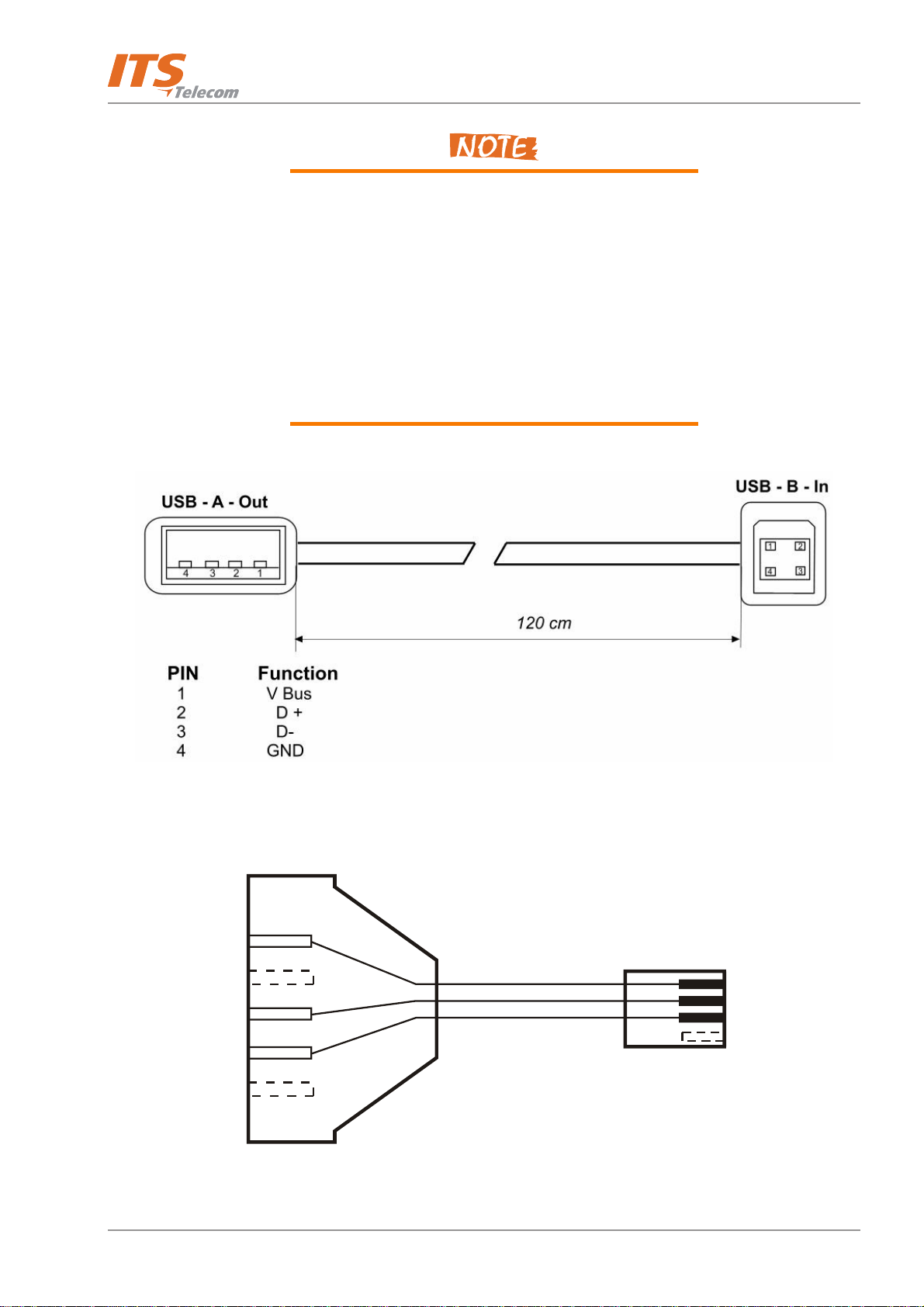
For the electrical diagram of the USB and RS-232 cables,
see Figure
2-1 and Figure 2-2.
If the Voice Mail System includes the 4 ports extension
and/or the Unified Messaging module, a metal cover with
2 screws for the expansion card hole will also be in the
box.
Figure 2-1: USB Cable Electrical Diagram
To P
5
3
2
D-type, 9 pins, Female RJ-11, 4 pins, Male
Figure 2-2: RS-232 Cable Electrical Diagram
To Vo i ce M ai l Sys te
1
2
3
2-2

Installation
RJ-11
Analog Port Input
4
3
2
1
Figure 2-3: Analog Ports Input Cable
2.2 Hardware Installation
This section contains the following:
Voice Mail System installation
Connections, starting up and initial indications
Voice Mail System expansion to eight ports
RJ-11
Analog Extension Socket
4
3
2
1
VMS programming can be done prior to the hardware
installation (see VMS Programming in Chapter 3). After
the programming, proceed with the hardware installation
and connections (see this section) and transfer the
configuration and recording files to the Voice Mail
System (see Accessing VMS Programming Data in
Chapter 4).
2.2.1 Voice Mail System Installation
¾ To install the Voice Mail System in a 19" rack (see Figure 2-4):
a. Attach a bracket to each side of the Voice Mail System unit, adjacent to its front panel and fasten each
bracket with the three screws provided.
b. Place the Voice Mail System unit in the 19" rack and fasten it to the rack rails, using four screws,
washers and spring washers.
2-3

Installation
Figure 2-4: Installation of Voice Mail System in a 19” Rack
¾ To install the Voice Mail System on a wall (see Figure 2-5):
a. Attach a bracket to each side of the Voice Mail System unit, adjacent to its top panel (see Figure 2-3)
and fasten each bracket with the two screws provided.
b. Drill four holes in the wall.
c. Fasten the Voice Mail System unit to the wall using four screws, washers and spring washers provided.
Figure 2-5: Installation of Voice Mail System on the Wall
2-4

Installation
2.2.2 Connections, Starting Up and Initial Indications
a. Connect each port (4 or 8) to an extension line, using an RJ-11 cable. The ports can be found on the right
side of the front panel of the Voice Mail System unit.
Each RJ-11 socket on the front panel of the Voice Mail
System supports one analog telephone line.
Make sure that the Analog Ports Input Cables are
according to the specifications in Figure
2-3.
In order to prevent damage to the USB/RS-232 driver
chips, DO NOT connect an analog telephone line to the
RS-232 socket.
b. Plug the RJ-45 Network cable into the Ethernet socket of the Voice Mail System front panel.
c. Plug the 9V DC adapter jack into the power supply connector on the left side of Voice Mail System front
panel.
d. Plug the 9V DC adapter into the main power supply outlet, to turn the Voice Mail System on.
e. Notice the indications on the LCD display. For details, see LCD Messages in Chapter 4.
f. For initial programming of the Voice Mail System (the LAN settings), connect the USB/RS-232 cable between
the Voice Mail System’s USB/RS-232 socket and the COM port of the PC running the VMS program. All
other settings can also be performed now, but the administrator has the choice to execute this task via
TCP/IP.
Voice Mail system has following default TCP / IP settings:
IP Address: 192.168.21.200
Subnet mask: 255.255.255.0
Gateway Address: 192.168.21.1
It can be used for the first TCP/IP connection and can be
changed using DTMF programming codes – see DTMF
programming codes table *020, *021, *022).
2-5

Installation
g. Remote programming of the Voice Mail System can be done either via TCP/IP or via a modem connected to
the public network. The Administrator has to enable this option in the Voice Mail System.
Voice Mail System connections for local and remote
programming, are schematically shown in Chapter 1.
For local programming, a USB cable is included in the
Voice Mail System package.
h. Call each Voice Mail System line from any extension and listen to the default greeting, informing you that
the system has not been programmed yet (see VM System Messages, System Message No. 000).
2.2.3 Physical Expansion
The Voice Mail System can be configured in one of the following combinations:
4 or 8 analog ports
4 analog ports with Speech Recognition feature
4 analog ports with Speech Recognition feature and full unified messaging (Voice & FAX messages)
features
8 analog ports with partly unified messaging features – (Voice only)
8 analog ports with full unified messaging features – (Voice & FAX messages*)
Voice messages E-mail notification enabled in default
configuration.
FAX feature requires special hardware fax license key
installation on the expansion 4-line module or Speech
Recognition module.
The Speech Recognition module firmware includes
default language support, which cannot be changed at
the customer's site.
*Check with the local distributor if existing system
firmware supports the NO-ECM mode supported fax
messages handling. Error correction mode (ECM) is an
optional transmission mode built into Class 1 fax
machines or fax modems.
2-6

Installation
For a physical upgrade of the Voice Mail System, one of the following three expansion modules:
Speech Recognition 4-Line module
Unified Messaging Fax License expansion module
4 ports, 72 hours of memory expansion module
4 ports, 72 hours of memory and Unified Messaging Fax License expansion module
¾ To upgrade a Voice Mail System unit:
a. Make sure that the Voice Mail System is not connected to the power supply.
b. Remove the two screws and the cover from the expansion slot on the right side of the front panel (see
Figure 2-6).
c. Slide the expansion card into the slot and carefully push it in until it fits into the unit's rear connector.
d. Fasten the expansion card, using its two captive screws to the unit's front panel.
e. Plug in the power supply.
The Voice Mail System will automatically detect the new module and activate the additional features.
Figure 2-6: Expanding the Voice Mail System
2-7

Installation
2.3 Software Setup
This section contains the following:
Installing the VMS software
Selecting a PBX
Configuring the VMS toolbars
Setting the location of the Voice Mail System files
2.3.1 Installing the VMS Software
Install the VMS software on the Administrator’s PC or laptop. This PC or laptop is being used for the setup,
programming and managing of the Voice Mail System unit.
The VMS software can be installed and used for creating
the Voice Mail System configuration and programming
scripts, without physically connecting the PC to the Voice
Mail System unit.
The following may happen when the PC containing the
VMS software is physically connected to the Voice Mail
System unit. A message, indicating that the COM port of
the PC has not been configured, may appear, when
performing a software download. Click OK and configure
the COM port.
To establish a connection, follow the relevant procedures:
Connections, Powering Up and Initial Indications in
Chapter 2 and Setting the VMS PC – Voice Mail System
Communication in Chapter 4.
VMS installation procedure requires selecting the Speech
Recognition default language. If the Speech recognition
module is not installed or the local language is not
displayed, it is recommended to select English. If the
Speech recognition module is installed, select the VMS
Speech recognition language that corresponds to that as
displayed in the Speech recognition firmware.
2-8

Installation
¾ To install the VMS software:
a. Insert the VMS CD in the CD-ROM drive of your PC. The CD should run automatically.
b. If the CD does not run, click Start Æ Run and browse the CD for the VMS Set up icon.
c. Click on the VMS Installation icon and follow the instructions on the screen.
d. To start the VMS program, either click Start Æ Programs Æ Voice Mail System or double-click the
VMS – Voice Mail System icon on the PC desktop. The VMS – Voicemail Maintenance Software
main screen appears (see Figure 2-7).
Figure 2-7: VMS Main Screen
2.3.2 Installing the USB Driver
The USB installation driver software is included on the supplied CD. Please note, that you must select a driver
that corresponds to the operation system installed on your PC. If an update is required, you can find the drivers
you need on the following web page: http://www.ftdichip.com/Drivers/VCP.htm
There are two stages of USB driver installation:
USB serial driver installation
USB port driver installation
¾ To install a serial driver, perform the steps as follows:
a. Power the Voice Mail device using the 9V DC external power supply.
b. Plug a USB cable into the Vocal Baby device and the PC USB port. Found New Hardware screen appears.
.
2-9

Installation
Figure 2-8: Found New Hardware Screen
If the new hardware is not detected automatically, perform the steps as follows:
a. Right-click My Computer icon and select Manage from pop-up menu. Computer Management screen
appears.
b. Click the Device Manager branch. The device management tree appears on the right.
c. Right-click Universal Serial Bus controllers and select Scan for hardware changes from pop-up menu.
After a few seconds Found New Hardware Wizard screen appears (Figure 2-9).
Figure 2-9: Found New Hardware Wizard – Screen 1
d. Click Next. The next wizard screen appears (Figure 2-10).
2-10

Installation
Figure 2-10: Found New Hardware Wizard – Screen 2
e. Click the Search for a suitable driver for my device (recommended) radio button and click Next. The
next wizard screen appears (Figure 2-11).
Figure 2-11: Found New Hardware Wizard – Screen 3
f. Select the Specify a location check-box and click Next. A standard Windows browser opens (Figure 2-12).
2-11

Installation
Figure 2-12: Found New Hardware Wizard – Screen 4
g. Select the USB driver’s files location on the supplied CD and the operation system installed on the PC, and
click Open. The next wizard screen appears (Figure 2-13).
Figure 2-13: Found New Hardware Wizard – Screen 5
h. Click Next. An installation procedure is performed (Figure 2-14).
2-12

Installation
Figure 2-14: Found New Hardware Wizard – Screen 6
i. Click Next. A new screen informs that USB-COM serial converter installation is completing (Figure 2-15).
Figure 2-15: Found New Hardware Wizard – Screen 7
j. Click Finish to finish USB-COM port converter installation and start the USB port installation. Found New
Hardware screen appears (Figure 2-16) and after a few seconds Found New Hardware Wizard screen
appears (Figure 2-17).
Figure 2-16: Found New Hardware Wizard – Screen 8
2-13

Figure 2-17: Found New Hardware Wizard – Screen 9
k. Click Next. The next wizard screen appears (Figure 2-18).
Installation
Figure 2-18: Found New Hardware Wizard – Screen 10
l. Click the Search for a suitable driver for my device (recommended) radio button and click Next. The
next wizard screen appears (Figure 2-19).
2-14

Installation
Figure 2-19: Found New Hardware Wizard – Screen 11
m. Select the Specify a location check-box and click Next. A standard Windows browser opens (Figure 2-20).
Figure 2-20: Found New Hardware Wizard – Screen 12
n. Select the USB driver’s files location on the supplied CD and the operation system installed on the PC, and
click Open. The next wizard screen appears (Figure 2-21).
2-15

Figure 2-21: Found New Hardware Wizard – Screen 13
Installation
o. Click Next. A new screen informs that USB-COM serial port installation is completing (Figure 2-22).
Figure 2-22: Found New Hardware Wizard – Screen 14
p. Click Finish to finalize the installation process.
¾ To test the connection between PC and Voice Mail perform the steps as follows:
a. Run the VMS software from the supplied CD.
b. From the main menu select CommunicationÆRead Configuration and click OK. VMS starts reading
the configuration from the Voice Mail system through the USB interface. If the VMS application does
not find USB port automatically, you can resolve it as follows:
2-16

Installation
− Right-click My Computer icon and select Manage from pop-up menu. Computer
Management screen appears (Figure 2-23).
− Click the Device Manager branch. The device management tree appears on the right.
Figure 2-23: Computer Management Screen
− Find the installed USB Serial Port and the corresponding PC COM port.
− On the VMS application main menu select CommunicationÆCom Port. USB To COM Port
Selection screen appears (Figure 2-24).
Figure 2-24: USB To COM Port Selection Screen
− Set the COM port as required.
− Try to activate the Read Parameters function again.
2-17

Installation
2.3.3 PBX Selection
Selecting a PBX from the PBX Selection list enables a quick and easy integration of the Voice Mail System. All the
default parameters for the selected PBX will automatically be shown in the VMS. These parameters are:
Transfer Code
Hook Flash Time
Message Light On and Off codes
In-band DTMF Protocol
Refer to PBX Settings in order to change the parameters not provided in the PBX selection.
¾ To select a PBX:
a. Click the PBX Selection button in the VMS toolbar.
b. From the PBX Selection dialog (see Figure 2-25), select the relevant PBX and click OK.
Parameters applied when selecting a PBX, may differ from the
parameters of the existing PBX. In this case, you may require
assistance from the PBX manufacturer and/or from Aleen
Technologies Technical Support.
To obtain a list of the PBX parameters from the VMS main
menu, select File ÆPrint Settings Menu ÆPBX Parameters.
Figure 2-25: PBX Selection List
2-18

2.3.4 Configuring the VMS Toolbars
This function is used for selecting which toolbars and whether tool tips will be displayed.
¾ To configure the VMS toolbars:
a. From the VMS main menu, select File Æ Options. The Options dialog appears (see Figure 2-26).
Installation
Figure 2-26: Toolbar Configuration Tab
b. In the Tool Bars section, check the boxes of the required toolbars.
c. In the Tool Tips section, click Hide to only show the tool name when moving the cursor over it.
d. Click OK to confirm your settings.
2-19

Installation
2.3.5 Setting the Location of the Voice Mail System Files
This function is used to set the path for the Voice Mail System configuration and data files.
¾ To set the location of the Voice Mail System files:
a. Select File ÆOptions and click the File Location Tab (see Figure 2-27) from the VMS main menu.
Figure 2-27: File Location Tab
b. The file list contains:
File Type Usage
VMP Configuration
VOX System initiation
WAX Backup
Script files Opening greeting script
WAV Window media format
BIN Voice Mail System Software version
c. To change the location of a file type, highlight it, click the Set location button and type in the new
location.
d. To delete the location of a file type, highlight it and click the Clear location button.
e. Click OK to confirm your changes.
2-20

VMS Programming
Chapter 3: VMS Programming
This chapter contains the following:
Quick Voice Mail System Installation using the Installation Wizard
Programming the Voice Mail System’s system parameters
Programming the Voice Mail System's Automated Attendant (AA)
Programming the Voice Mail System's Voice Mail (VM)
To program the Voice Mail System unit using a touch-tone telephone, see Chapter 6, DTMF
Programming.
3.
3.1 Quick Installation Using the Installation Wizard
The Voice Mail System Installation Wizard is especially recommended as the initial fast, hands-on installation
tool.
¾ To use the Voice Mail System Installation Wizard:
a. Select Wizard Æ Start from the menu bar or click on the Installation Wizard icon
on the toolbar.
b. After opening the Wizard, click Start. The first out of the following ten dialogs will appear.
c. In these dialogs, enter the following parameters:
No. Dialog Description Reference
1
2
3
4
5
6
PBX Parameters
PBX Parameters
PBX Parameters
List of Mailboxes
Notification Parameters
In-band DTMF Protocol
Operator Extensions, Fax Extensions, PBX Legal
Extensions
Transfer mode
Busy Tone, Disconnect Tone
Range of mailboxes
PBX code used to turn the message light on and
off
Codes from a PBX that supports the In-band
DTMF Protocol to the Voice Mail extension
Figure 3-1
Figure 3-2
Figure 3-3
Figure 3-19
(similar)
Figure 3-23
(similar)
Figure 3-6
7
3-1
In-band DTMF Protocol
See pages 2-4 for additional 30 events -

VMS Programming
No. Dialog Description Reference
8
9
10
Script Menu
Network Parameters
Final Wizard Script Finish to save your settings or Cancel to return
The operation associated with each script
Relevant Network settings for the Voice Mail
System
to the Voice Mail System opening screen without
saving the Wizard settings
3.2 System Programming
To program the Voice Mail System’s system parameters, the following procedures apply:
Setting the PBX parameters
Setting the system parameters
Setting the In-band DTMF Protocol parameters
Setting the Network Parameters
Figure 3-9
3.2.1 Setting the PBX Parameters
For programming the PBX parameters of the Voice Mail
System unit using a touch-tone telephone, see Chapter 5.
¾ To use the Voice Mail System Installation Wizard:
a. Select Parameters Æ PBX Parameters from the menu bar or click on the PBX Parameters icon
the toolbar. The PBX Parameters dialog appears (see Figure 3-1).
on
3-2

VMS Programming
Figure 3-1: PBX Parameters Dialog
b. In the Extensions tab, enter the numbers and ranges of the PBX extension types (enter two to six digits
in the extension number fields of Figure 3-1):
Extension Type Usage
Operator Defines eight Operator extensions for script and mailbox programming.
PBX Legal Extension Defines 10 extension ranges for Direct Call to Extension. Extensions outside these
ranges cannot be directly accessed via the Automated Attendant scripts.
Fax Defines four extensions for “call transfer”, on detection of the fax tone by the Voice
Mail System. Leaving these fields empty disables the feature.
c. In the Call Transfer tab, set the call transfer parameters (see Figure 3-2).
3-3

VMS Programming
Figure 3-2: Call Transfer Tab
Parameter Usage
Transfer Supervise Type Defines the method for detecting the No Answer, Busy and Do Not Disturb (DND)
status when a call is transferred to an extension in semi-supervised or supervised
mode. Select:
Type Details
Call Progress Tones The Voice Mail System samples the ring
cadences from the PBX (Busy tone,
Disconnect tone, etc.).
DTMF The Voice Mail System receives the
DTMF signals for Busy, No Answer and
DND from the PBX.
DTMF Codes from PBX Defines the Answer, Busy and DND DTMF signals after switching to DTMF in the
Transfer Supervise Type drop-down menu.
Transfer Mode Defines the transfer mode of the Operator and other extensions. Select:
Mode To
Non-supervised Transfer the call without checking the
status of the extension.
3-4

VMS Programming
Parameter Usage
Semi-supervised Check for a Busy signal on the required
extension. If the called extension is not
busy, then the call is transferred in a
non-supervised fashion.
Supervised Check for a Busy signal or No Answer
timeout on the required extension. The
system waits for the call to be
answered before the call the transfer is
completed.
Transfer Code Transfers a call from the Script or Personal greeting to another telephone number.
The applicable codes are:
Code To indicate
& Hook flash
X Extension
0-9, A-D DTMF
P Pause
Recall from Busy Code Defines the PBX code to return the caller to the Voice Mail System when the
required party is busy (this code is applicable for semi-supervised or supervised
mode only).
Recall from No-answer
Code
Recall from Hold on
busy retry Code
Defines the PBX code to return the caller to the Voice Mail System when his/her call
is not answered (this code is applicable for supervised mode only).
Defines the PBX code to return the call placed on Hold during the “Busy menu”
playback to the Voice Mail System.
Hook Flash Time (&) Defines the hook flash time in milliseconds.
Time to Wait for No
Defines the Voice Mail System waiting period for an answer after transferring a call
Answer
in supervised mode (the default is 20 seconds).
Voice Sensitivity Defines the sensitivity to human voice detection on the destination extension in
supervised mode (default is 5).
3-5

VMS Programming
d. In the CP Tone & Disconnect tab, the on-time and off-time of the following tones are set (see Figure
3-3):
Figure 3-3: CP Tone & Disconnect Tab
Tone Usage
Busy, External Busy Detects a busy tone on the line and disconnects the line when a busy tone
is detected.
Disconnect,
External Disconnect
e. Enter the Disconnect Code. Defines the DTMF codes sent from the PBX to the Voice Mail System, in
order to disconnect the line, when a caller has hung up.
Disconnects the line when the caller hangs up and the disconnect tones
are detected.
3-6

VMS Programming
3.2.2 System Parameters
For programming the system parameters of the Voice Mail
System unit using a touch-tone telephone, see Chapter 5.
¾ To set the system parameters:
a. Select Parameters Æ System Parameters from the menu bar. The Parameters tab appears (see
Figure 3-4).
Figure 3-4: System Parameters Tab
b. Select the Default System Language by clicking on the appropriate radio button.
The list of installed languages will only be shown after a
Read Parameters operation.
Use the Statistics window (see Chapter 4) after a “Read
Parameters” operation, to check the number of the
languages installed in the system. For a new system, the
number of installed languages is also specified on the
package.
3-7

VMS Programming
c. Select Last or First Name to be used as selection, when using the Directory Listing feature.
d. Click the Advanced button to change parameters, which affect the unit's operation as indicated by an
appropriate warning message.
e. On receiving the warning message, click Yes to enter the Advanced Parameters dialog
(see Figure 3-5).
Figure 3-5: Advanced Parameters Dialog
f. Modify and mark the parameters in the Advanced Parameters dialog.
3-8

g. Define system parameters as follows:
Parameter Usage
VMS Programming
Delay before notification
dialing
Pause before/after
external access code
Number of answer
samples
Maximum recording
time
Defines the time delay in seconds, before a dialing notification string is sent
(before going off-hook).
Defines the time delay before/after dialing an external line access code.
Defines how fast the Voice Mail System in Supervisor mode will recognize a
human voice from a called extension.
Defines the maximum recording time for user messages, mailbox greetings
and names.
Volume level Defines the volume level of a message played via an analog port. (see
DTMF – command *369). This parameter is used only for changing volume
of user-recorded messages.
To change the volume level of System Messages (Prompts), use *368 where
x=0,9 default=5.
Another new parameter is Amplification Factor. The legal values for it are
0-9 (default 5). To program this via DTMF use command *367 X where
X=0-9.
h. Check boxes as necessary:
Check To enable
Q23 protocol support A special protocol, when integrating the Voice Mail System with the
MATRA PBX.
Loop Disconnect Enable Voice Mail System detection of a call interruption from the PBX side
initiated by the caller.
i. In the DTMF Setting section, the dual arrow buttons can be used to enter the relevant DTMF
parameters.
3-9

VMS Programming
Parameter Usage
DTMF Sensitivity Level Defines the sensitivity for DTMF tones dialed by the PBX.
DTMF Amplitude Defines the outgoing DTMF tone level.
DTMF Off Time Defines the DTMF tone cadence Off time (pause in 20 msec steps) dialed by
the Voice Mail System.
DTMF On Time Defines the DTMF tone cadence On time (active tone in 20 msec steps) time
dialed by the Voice Mail System.
DTMF Input Timeout Defines the maximum time between DTMF signals, in which the caller has
to enter the relevant data.
DTMF Disconnect Code
Length
Defines the length of the DTMF cadence cycle, sent by the PBX, when a call
is disconnected. This parameter is needed in order to calculate the amount
of time that must be truncated from the end of a message, which was
terminated by a Disconnect Code.
DTMF Minimum Input
Length
Defines the length of the DTMF ON tone, used by the PBX. This parameter
helps to differentiate between voice and actual DTMF input digits. The
DTMF tone that is shorter than minimum input length will be ignored.
j. To enable Active System Messages, check boxes as follows:
Check To enable
Please hold System message 003. Playback before transferring a call.
You have a call System message 011. Playback after the target extension answered (for
supervised transfers only).
Please leave a message
System message 008. Additional options after leaving a message.
after the tone
Please say the name of
the person
System message 277. Enables system message after the Script Opening
Greeting playback when the Speech Recognition feature is activated.
3-10

VMS Programming
k. To enable the modem, check boxes as follows:
Check To enable
Modem Enable Modem, connecting from a remote PC
Modem Activation Code Activation code for the built-in Voice Mail System modem (valid codes are 0-
9, A, B, C, D and #. * cannot be used!)
l. To initiate the system, upload system messages and restore the default system parameters, click the
System Init button. Use the Browse option to define the path of the *.VOX file.
Please notice that following the system initialization, all
previously recorded messages are deleted.
For a system initialization, a special *.vox file must be
used, prepared by the manufacturer. Using the incorrect
*.vox file or a file of any other format can destroy the
Voice Mail System.
To upgrade the Voice Mail System application software use the
designated utility supplied by the manufacturer to your local
authorized distributor.
3-11

VMS Programming
3.2.3 In-band DTMF Protocol
The In-band DTMF Protocol is used for defining DTMF strings, sent from the PBX to the Voice Mail System. The
Voice Mail System uses these DTMF digits to identify the condition or reason why an incoming call is arriving to
the Voice Mail System. Typically, they tell the Voice Mail System of a call-forward situation or a log in attempt.
Each In-band DTMF Protocol event string is associated with an operation that is executed once the Voice Mail
System receives a DTMF string. A string contains up to 40 digits: 0 to 9, A to D, #, and *.
For programming the In-band DTMF Protocol of the Voice
Mail System unit using a touch-tone telephone, see Chapter
5.
¾ To define the system behavior according to the port that receives the call:
a. Select Parameters Æ In-band DTMF Protocol from the menu bar. The In-band DTMF Protocol
dialog appears (see Figure 3-6).
On the four tabs of the In-band DTMF Protocol screen, up
to 40 DTMF operations can be defined.
Figure 3-6: In-Band DTMF Protocol Dialog
b. Enter the Code Received from the PBX and select the required Operation from the operation drop-
down menu on the right.
3-12

VMS Programming
Select To
Auto Attendant Play the opening script of the Automated Attendant.
Transfer to a Script
Message
Transfer to a script
Play a specific script.
Play a specific script and change to the specified language (1, 2 or 3).
Message + 1st/2nd/3rd
Language
Transfer to Busy Menu Play the default system Busy menu.
Transfer to No Answer
Play the default system No Answer menu.
Menu
Transfer to Do Not Disturb
Play the default system Do Not Disturb menu.
Menu
Transfer to an Extension Transfer a call to a required extension.
Transfer to a Mailbox Transfer a call to a required mailbox.
Transfer to the Operator Transfer a call to a required operator, 1 out of 8.
Directory List Play the Directory Listing (DBN)
Call Recording Record the conversation. (This is only applicable to a PBX, where the Call
Recording feature is supported.)
Leave a Message Leave a message in a designated mailbox.
Retrieve Messages Retrieve messages from a designated mailbox.
Disconnect Disconnect the call.
Transfer to a Group of
Leave a message for a group of mailboxes.
Mailboxes
c. Set the maximum time interval that the Voice Mail System has to wait in milliseconds, until the first
DTMF string is received.
d. Set the maximum time delay between DTMF codes sent from the PBX to the Voice Mail System to
detect the end of the In-Band-DTMF code.
3-13

VMS Programming
On the four tabs of the In-band DTMF Protocol screen, up
to 40 DTMF operations can be defined.
e. Click the OK button to confirm your settings and return to the VMS main screen.
Example: Let us assume a caller calls in and is transferred to station 215 and there is no answer and
station 215 is programmed for call-forward-no-answer to the voicemail. If the PBX sends on a call-
forward-no-answer condition the digits “9 1 2 1 5” and we want to make sure that the caller is sent to
voice mailbox for station 215, then we would program in the In-band DTMF Protocol event string as in
Figure 3-7:
Figure 3-7: In-Band DTMF Protocol Table
3-14

3.2.4 Network Parameters
Voice Mail system has the following default TCP / IP settings:
IP Address: 192.168.21.200
Subnet mask: 255.255.255.0
Gateway Address: 192.168.21.1
It can be used for the first TCP/IP connection and can be
changed using DTMF programming codes – see DTMF
programming codes table *020, *021, *022.
To define large-scale network parameters, you may need a
Local Network Administrator’s assistance.
VMS Programming
The Local Network Administrator needs to define a
user/email account for the Voice Mail System on the Email
Server.
The Network Parameters are also needed for the
administrator’s use of the VMS remotely (via TCP/IP).
To enable network features, the Voice Mail System needs to be integrated into the TCP/IP protocol based Local
Area Network. Enter the Voice Mail System to the LAN as a regular Network user. This is possible via the
definition of the Network Parameters.
To allow for the possibility to send emails from the Voice Mail System to mailbox owners, the IP address of the
SMTP server needs to be defined. A mailbox for the Voice Mail System needs to be defined on the Local Area
Network. For this the help of the Local Network Administrator is needed.
¾ To define network parameters:
a. Select Parameters Æ Network Parameters from the menu bar. The Network Parameters dialog
appears (see Figure 3-8).
3-15

VMS Programming
Figure 3-8: Network Parameters
Parameter Usage
Device Properties –
IP Address
Device Properties –
Subnet Mask
Gateway Properties –
IP address
Server Properties –
IP Address
Mail Account Properties Voice Mail System Email account in the SMTP mail server.
Email Address Defines the email address for the Voice Mail System, as defined in the local
Defines the permanent Voice Mail System IP Address, which has to be
unique in the existing LAN. (DHCP is currently not supported.)
Defines the Subnet Mask for the existing LAN.
IP Address of the Network Communication device (Router, Firewall, etc.),
which establishes connection with external Network resources.
Local SMTP Mail Server IP Address.
mail server. This address is needed when the Unified Messaging feature is
activated for SMTP Email sender recognition.
User name Voice mail system user account name in the Email server, which needs
SMTP E-mail sender authorization.
Password Voice mail system user account password in the Email server, which needs
SMTP E-mail sender authorization.
3-16

VMS Programming
3.3 Automated Attendant Programming
The following steps apply to the programming of the Voice Mail System Automated Attendant:
Script programming
Schedule programming
3.3.1 Script Programming
Defines the operation executed when pressing any DTMF digit between 0 and 9, while the script message
is being played, etc.
Defines speech recognition programming rules.
Defines the script opening conditions per port and the number of the script to be played for each port.
Defines a name for each necessary operational script, i.e. company greeting in English, script 00 and
company greeting in Spanish, script 01, etc.
Displays of script listings for reviewing the script status.
For programming the AA script of the Voice Mail System,
using a touch-tone telephone, see Chapter 5.
Please note that a script must be recorded and programmed
with an announcement, in order for a script to operate.
¾ To define DTMF strings, using the in-band DTMF protocol:
a. Select Auto Attendant Æ Script Menu from the menu bar. The Script Menu appears
(see Figure 3-9).
3-17

VMS Programming
Figure 3-9: Script Programming Tab
b. To define an operation for each DTMF digit (0 to 9), select the respective Type of Operation from the
drop-down menu. The operations to choose from are as follows:
Operation When pressing appropriate DTMF digit
No entry No operation.
Transfer to a script menu The caller is transferred to the sub-menu, defined in the
respective Destination field.
Transfer to a Script Message + 1st
Language,
Transfer to a Script Message + 2nd
The caller is transferred to the sub-menu, defined in the
respective Destination field and the selected system language is
used until the end of the session (unless otherwise changed).
Language,
Transfer to a Script Message + 3rd
Language
3-18

VMS Programming
Operation When pressing appropriate DTMF digit
Directory List The Voice Mail System requires the caller to enter the first three
letters of the first or last name of the required party (for details
regarding the dial by name option, see System Parameters).
Note: Each mailbox owner, who wants to be reachable via
DBN, must enter the name 3-digit code and record the name
followed by the user’s menu; for details regarding the Dial by
Name option, see System Parameters (Paragraph 3.2.2).
Transfer to an Extension The call is transferred to the predefined extension, as defined in
the relevant Destination field. If the target mailbox has the Call
Screening function activated, callers will be requested to record
their name and the destination will be informed of the calling
party.
Transfer to a Mailbox The caller is immediately sent to the required mailbox, defined
in the relevant Destination field.
Transfer to a Group of Mailboxes Leave a message for a mailbox group.
Direct Call to an Extension Allows the caller to dial the required extension number, which
is a legal PBX extension For additional details, see PBX Settings
(Paragraph 3.2.1). Direct Call feature must be defined for the
first digit of the legal PBX extensions range.
Direct Call to a Mailbox Allows the caller to dial the required mailbox.
Leave a Message Allows the caller to press a predefined digit from 0 to 9, and is
then prompted to enter the requested mailbox number for
leaving a message.
Retrieve Messages Allows the caller to press a predefined digit from 0 to 9 and is
then prompted to enter the required mailbox number and
personal password, in order to retrieve messages.
Disconnect The caller is disconnected.
Disconnect with Message The caller is "politely" disconnected, as the Voice Mail System
plays the message “Thank-you and good-bye” before
disconnecting.
Return to Main menu Returns the caller to the currently active menu.
3-19

VMS Programming
Operation When pressing appropriate DTMF digit
Dial a String Enter a string number from the Dial Strings table to dial the
free up to 40 DTMF symbols DTMF string (see Figure 3-14).
Transfer to Operator A caller can be transferred from a script message to an
Operator, as defined in the PBX Settings.
Import WAV A *.wav file can be imported and can be transferred to a
specified script, such as a greeting message.
c. To define the number of times the Script Opening Greeting playback is played, set the Repeat script
parameter.
d. To define the time interval after the Script Opening Greeting, in which the caller needs to respond, set
the EOM Timeout in seconds.
e. Define in each script one fax extension out of four, to which a fax call will be directed. Please note that
each script menu can have a different fax extension.
f. To define a source *.wav file for a specified script, such as the opening greeting message, click the
Import WAV button.
The *.wav source file parameters are: PCM, 8 KHz,
16-bit, mono.
¾ To define the speech recognition programming:
The speech recognition programming is done by means of defining specific words in the designated table. When
the user will say a word form the list, the system will recognize them and respond accordingly. If the system fails
to recognize a word, the user will be prompted to repeat it. If still unrecognized after several retries, the call will
be routed according to the active script settings.
1. In the Script Menu, click on the Script Recognition tab (see Figure
3-10).
2. Use the PREV and NEXT buttons to browse to the required table.
It is possible to create up to 100 tables. Each table can
contain up to 100 entries. The total number of entries in all
tables is 800.
3-20

VMS Programming
3. Enter a name in Table name field (up to 30 text symbols). The supported language appears on the right of
this field. This language is fixed and cannot be changed by the user, since it does not depend on the
installed languages.
The speech recognition function requires the installation of
the appropriate hardware module.
Figure 3-10: Speech Recognition Tab
¾ To add a speech recognition entry:
a. Click the Add button. Speech Recognition Entry window opens (Figure 3-11).
b. Enter text in Speech text field (up to three words). This text will be recognized by the voice mail system.
c. Select an auto-attendant action from Action combo-box. When the speech is recognized, the selected
action is performed.
d. Enter a value in Destination field. This value represents the target extension/mailbox number or script
number.
3-21

VMS Programming
It is legal that several entries will be associated with the
same extension; it is illegal that a single entry will be
associated with more than one extension.
Figure 3-11: Speech Recognition Entry
¾ To edit a speech recognition entry:
a. Select an entry on the Speech Recognition table.
b. Click Edit. Speech Recognition Entry window opens (Figure 3-11).
c. Modify the settings as required.
d. Click OK to confirm. The changes are applied.
¾ To delete a speech recognition entry:
a. Select an entry on the Speech Recognition table.
b. Click Delete.
¾ To activate a speech recognition table:
a. Access the Script Programming tab (Figure 3-9).
b. In the Speech Recognition area at the bottom of the tab select a table from the Data base table
combo-box.
c. Select the Active checkbox. The table is activated.
3-22

VMS Programming
¾ To define DTMF strings, using the in-band DTMF protocol:
a. In the Script Menu, click on the Script Opening tab (see Figure 3-12).
b. Set for each port in use, the Number of Rings before a call is answered.
c. Set the script number played on each port. There can be up to four scripts – a script for each mode of
operation, i.e. Day, Night, Break or Holiday.
Figure 3-12: Script Opening Tab
3-23

VMS Programming
¾ To review the status of the scripts:
a. In the Script Menu, click on the Script Status tab (see Figure 3-13). The status of all programmed and
recorded scripts is displayed adjacent to the script number by means of an icon:
b. Ear icon for a recorded script
c. Network icon for a programmed script
d. Lamp icon for a programmed and recorded script
Figure 3-13: Script Status Tab
Status is only shown once read parameters have been
performed on the Voice Mail System.
e. Click the Description button to enter script details (for example, the script file name for future
reference).
3-24

¾ To define dial strings:
a. In the Script Menu, click on the Dial Strings tab (see Figure 3-14).
VMS Programming
b. Define up to 20 dial strings.
A dial string consists of up to 40 digits including 0 to 9, A to
D, *, #, p for 1 second pause, Q for 4 seconds pause and &
for hook flash.
Example: To perform a trunk-to-trunk transfer to the
telephone number 1 (800) 991-8186, the dial string field
might look like the following: &p9p18009918186pppp
The voicemail automatically hangs up after the last character
is performed in the dial string.
¾ To end the Script Menu session:
Figure 3-14: Dial Strings Tab
a. Click OK to save your settings or click Cancel to return to the Voice-mail Utility Program's (VMS) main
screen, without saving any data.
3-25

VMS Programming
3.3.2 Schedule Programming
Schedule programming specifies the Auto Attendant functionality based on the daily, weekly and holidays
scheduling table.
For programming the AA scheduling script of the Voice Mail
System unit using a touch-tone telephone,
see Chapter 5.
¾ To define the system time and scheduling modes:
a. Select Auto Attendant Æ Time & Date from the menu bar or click on the Time & Date icon
the toolbar. Time, Date and Weekly Schedules dialog appears (see Figure 3-15).
on
Figure 3-15: Time, Date and Weekly Schedules Dialog
3-26

VMS Programming
b. In the Time & Date tab, change the daylight saving clock by using the Auto Day Light saving time
drop-down as required. The system supports both American and European DST. It is possible to program
DST using a touch-tone telephone and DTMF programming, when the combo-box is set to none.
The time is automatically changed at 2:00 a.m. on the
appropriate days when selecting the American or
European option.
c. To set the system time and date, use the appropriate fields in this tab.
The default System Time and System Date are
automatically received from the PC, running the VMS
software.
d. Select the scheduling modes from the Mode of Operation drop-down menu:
Select To
Auto Set the automatic scheduling mode
Day, Night, Break, Holiday Manually set the appropriate scheduling mode.
¾ To define the Weekly Schedule:
a. In the Time & Date tab, select the Auto option from the Mode of Operation pop-down menu and
click the Schedules button. The Auto (automatic scheduling) dialog appears (see Figure 3-16).
3-27

VMS Programming
Figure 3-16: Automatic Scheduling Dialog
Please notice that the Schedules button is only enabled
when selecting the Auto option from the Mode of
Operation drop-down menu.
Break, Night and Holiday scripts have to be recorded by
the Administrator. Otherwise the Voice Mail System will
automatically return to the Day manual mode.
b. In the Weekly Schedule tab, set the Day Time schedule. The example displayed in Figure 3-16 shows
that the Voice Mail System will play the day script message between 09:00 and 17:00 every day.
3-28

VMS Programming
¾ To define the Auto Breaks schedules:
a. Click on the Auto Breaks tab. The current list of auto breaks appears on Auto Breaks tab (see Figure
3-17).
Figure 3-17: Auto Break Schedules Tab
b. Define the breaks for each day by entering the times and selecting the script that has to be played.
c. To remove a break from the list, select the break and change the From and To time to 00:00.
3-29

VMS Programming
¾ To define the Holiday schedules:
a. Click on the Holiday’s Schedules tab. The current list of holiday dates appears (see Figure 3-18).
b. Click the Add button to add a new date to the list of holidays and set the time the holiday script
message should be played.
Figure 3-18: Holiday Schedules Tab
If the holiday lasts more than one day, each day must be
separately added to the list.
c. To remove a holiday date from the list, highlight it and click the Remove button.
¾ To end your time and date scheduling session:
a. Click the OK button to confirm your settings or click Cancel to cancel your settings and return to the
VMS main screen.
3-30

3.4 Programming the Voice Mail
Voice Mail programming contains the following:
List of mailboxes
Setting the message waiting notification
Defining mailbox groups
3.4.1 Handling the List of Mailboxes
The tasks associated with the list of mailboxes are:
Creating a range of mailboxes and defining a Supervisor Mailbox
Editing the list of mailboxes
Setting the parameters of the mailbox list
VMS Programming
To program the list of mailboxes of the Voice Mail System,
using DTMF programming, refer to Chapter 5.
¾ To create a range of mailboxes and define a Supervisor Mailbox:
a. Select Voice Mail Æ List of Mailboxes from the menu bar or click on the List of Mailboxes icon
on the toolbar. The List of Mailboxes dialog appears (see Figure 3-19).
3-31

Figure 3-19: List of Mailboxes
VMS Programming
b. To define a Supervisor Mailbox, select the correct mailbox from the drop-down menu.
The Supervisor Mailbox can only be defined after a number
of mailboxes have been created, as one of them will have to
be assigned as the Supervisor Mailbox.
The Supervisor Mailbox is used when the Voice Mail System
memory is 85% full. The System Administrator is alerted to
delete messages and reorganize the system memory.
c. To create a range of mailboxes, fill in the following:
Field With
From The first mailbox in the sequence.
To The last mailbox in the sequence.
Source The mailbox with specific parameters, e.g. language or operator, etc., which is the
source for the new mailbox parameters. All the new mailboxes created this way
will have the same exact configuration as the source mailbox.
d. When finished, click the Create Range button. The new mailboxes appear in the list of mailboxes and
the Total Number of Mailboxes is updated.
3-32

The maximum number of mailboxes supported in the Voice
Mail System is 500 total real and virtual mailboxes.
¾ To edit the list of mailboxes:
a. Use the right-hand buttons as follows:
Click To
New Create a new mailbox (see Figure 3-20).
VMS Programming
Copy
Delete
Create a new mailbox based on the parameters of a highlighted mailbox.
Delete the highlighted mailbox.
Edit Edit the parameters of the highlighted mailbox (see Figure 3-20).
b. To add a new mailbox, click the New button. New Mailbox screen appears (see Figure 3-20).
Figure 3-20: New Mailbox
3-33

Parameter To define
VMS Programming
Mailbox
Extension
Mailbox Type
User Language
The number of the mailbox in the list of mailboxes.
The number of the extension associated with the mailbox (for local notification use only).
The type of the mailbox, either real or virtual.
The language used by the mailbox when playing system messages.
A virtual mailbox has the same functionality as a real one,
except that it has no physical extension associated with it.
c. Click the Reset button to change the password to default (the default password is 1234). When
changing the User Password, four asterisks (****) appear.
d. To enable local notification for waiting messages, select one of the options from the Local Notification
pop-down menu:
Option Usage
Message Light 1 Turns on the message waiting light on the telephone or changes the dial tone of
the extension by sending the code defined in the Notification Parameters.
Message Light 2 Identical to Message Light 1, but for PBXs that support more than one type
message waiting notification code.
Sign Ring The Voice Mail System rings the extension number once to inform the mailbox
owner of new messages.
Rings The Voice Mail System rings an internal extension for a period of time defined by
the Ring Notification Duration and the Ring Notification Retries to inform the
mailbox owner of new messages. After the call is answered, the system provides
the user with the option of logging into the mailbox and checking messages.
3-34

VMS Programming
e. Check the Message Data options:
Check Function
Announcer Plays a personal greeting (announcement), without allowing a message to
be left.
Do Not Disturb Prevents call transfers from the Automated Attendant to extensions in
DND.
Time Stamp Plays the time and date of the message.
CLIP Activates the Calling Line Identification Presentation
Enable Call Screening Allows the use of the Call Screening function.
Active Call Screening Activates Call Screening for the mailbox owner.
f. Enter the maximum number of messages, which can be stored in the mailbox, using the appropriate
parameter.
3-35

VMS Programming
g. Check the Menu Activator options:
Option To
No Answer menu Activates the default system No Answer menu
Busy menu Activates the default system Busy menu
DND menu Activates the default system Do Not Disturb menu
h. Select one of the Personal Greeting options:
Option To
Busy/No Answer Greeting Activates the Busy and No Answer greetings for the mailbox.
Temporary Greeting Activates the Temporary greeting for the mailbox
i. Check the Copy Message options:
Option To
Copy to Mailbox Copies all incoming (non-forwarded) messages to another mailbox.
Move to Mailbox Moves all incoming (non-forwarded) messages to another mailbox
without storing any messages in the originating mailbox.
j. Select one of the Transfer Options:
Option To
Forward to Extension Forward a call from the Personal Greeting message to another
extension. When the caller dials the specified digit while the Personal
Greeting Message is played, the call is transferred to the predefined
extension.
Operator Forward a call from the Personal Greeting Message to one of the eight
local Operators defined in the PBX Settings.
Local Fax Transfers the call to a fax extension, when a fax data signal is detected
during the Personal Greeting Message, as defined in the PBX Settings.
External Fax Transfers the call to an external fax number during retrieving messages
from the mailbox using phone connection.
3-36

Option To
External Number Forward a call from the Personal Greeting message to an external
k. Check the Personal Fax options:
Option To
Enable personal fax Enables the mailbox owner to receive fax messages and save them in the personal
VMS Programming
number. When the caller dials the specified digit while the Personal
Greeting Message is played, a call is transferred to the predefined
external telephone number. This option is active if an External
notification allowed. The legal entries for this number are the same as
Dial a String options (0-9, *, #, A-D, 1 second Pause (P), 4 second pause
(Q), Hook Flash 1 (&), Hook Flash 2 (@), Extension Number (X)).
mailbox. The fax messages are retrieved during regular mailbox checking. The
system supports faxing of messages received as e-mail attachments, provided that
PMM software is installed.
*Check with the local distributor if the existing system firmware
supports the NO-ECM mode supported fax messages handling.
Error correction mode (ECM) is an optional transmission mode built
into Class 1 fax machines or fax modems.
l. Select one of the Forward Options:
Option To
Forward to Mailbox Automatically forwards a caller directly to another mailbox.
Forward to Script Automatically forwards a caller directly to a script. The target script has
to be recorded.
3-37

VMS Programming
m. Click on the External Notification tab. External Notification tab is displayed (see Figure 3-21).
Figure 3-21: External Notification
n. To enable external notification for waiting messages, select one of the following options:
Option Usage
Phone
If Allowed, the Voice Mail System calls the pre-defined phone number and
notifies the mailbox owner of new voicemail messages. The recorded message
is played on the remote telephone after the mailbox owner enters the correct
password and logs into the mailbox.
Pager
If Allowed, the Voice Mail System calls the pre-defined pager number and
displays a message notifying the mailbox owner of a new voicemail message.
o. Enter a number in Number field. This field supports DTMFs 0-9, *, #, A-D, also X (mailbox extension
number), P (1 second pause), Q (4 second pause), $ (wait for pager CPD tone), and ! (number of new
messages). There are 9 notifications destinations possible, which will be used in cascade order, based on
the From and To hour specified.
3-38

VMS Programming
p. To set parameters related to the cascade notification, use the following fields and check box:
Field Usage
Start Notification Delay Amount of time before first external notification is performed. Default is
30 minutes.
Notifications Time Interval Amount of time between external notifications in the cascade. Default is
30 minutes.
Loop Time Interval Optional. The amount of time between cascade loops or, more
precisely, the amount of time between the last scheduled external notify
in the cycle and next retry of the first notify in the cycle. Default is
disabled and 0 minutes.
q. To enable email notification and define required parameters, check the Enabled checkbox and fill the
following fields:
Field Usage
Email Target Relevant email address, where the mailbox owner can get the email
messages.
Email Notification Type From the drop-down menu, the email notification mode can be
chosen:
Without
Choice Description
The email will be sent to the target email
attachment
address, with information about a new recorded
message, but without a voice/fax message
attachment.
With voice
message attached
An email with the attached media file containing
the recorded message will be sent to the target
email address.
Message attached
and saved
An email with the attached media file containing
the recorded message will be sent to the target
email address and the message will be marked
as saved in the Voice Mail System. (Please note:
Since the message is marked as saved in the
voice mailbox, then no other notification shall
take place).
3-39

VMS Programming
Field Usage
Message attached
This delivery method is not secure! Network problems may
prevent the email message from being delivered properly
and all information will be lost.
¾ To set the mailbox parameters:
and deleted
An email with the attached media file
containing the recorded message will be sent
to the target email address and the message
will be marked as deleted in the Voice Mail
System (See Note) (Please note: Since the
message is marked as saved in the voice
mailbox, then no other notification shall take
place.)
a. In the List of Mailboxes, click the Parameters tab (see Figure 3-22).
Figure 3-22: Parameters Tab for List of Mailboxes
3-40

VMS Programming
b. Define the following general parameters for the list of mailboxes:
Parameter Usage
Operator ID Defines the key, when pressed while a Personal Greeting Message is
played, which allows a call to be transferred to the local Operator. Default
is 0
Retrieve Messages ID Defines the key, when pressed while a Personal Greeting Message is
played, which allows the caller to log into the current mailbox. Once the
digit is pressed, the caller is prompted for the password for the mailbox.
Default is 9
Transfer to Main Menu
ID
Defines the key, when pressed while a Personal Greeting Message is
played, which transfers a call to the Main Auto Attendant menu. Default
is 3
Transfer ID Defines the key, when pressed while a Personal Greeting Message is
played, which transfers a call to another backup extension. Default is 5
Transfer to External ID Defines the key, when pressed while a Personal Greeting Message is
played, which transfers a call to an external telephone number. Default is
7
Maximum Number of
Days to Store Messages
Defines the number of days that messages (new and saved) are stored in a
mailbox before they are automatically deleted. Default is 30
3.4.2 Setting Message Notifications
To program message a notification for the Voice Mail
System, using DTMF programming, refer to Chapter 5.
Email field can only be defined when using the VMS
software.
¾ To set the mailbox parameters:
a. Select Voicemail Æ Notification Parameters from the menu bar or click on the Notification
Parameters icon
on the toolbar. The Local and External Notification Parameters dialog appears
(see Figure 3-23).
3-41

Figure 3-23: Local and External Notification Parameters
VMS Programming
3-42

VMS Programming
b. Define the following notification parameters:
Parameter Usage
Status Notification Activates the notification function for the specified port. It is a forward hunting
sequence from the first enabled port to the last.
Note: Local and external FAX printing can be performed via ports available for
notification.
Message Light 1-Code Defines the code dialed by the Voice Mail System, from the port defined in the
Notification Parameters tab, which activates message waiting indicators on the desk
phone. Legal entries are:
Entry Meaning
X Extension number
P Pause
& Hook flash
! Number of new messages sent to the Voice Mail System LCD
(applicable only if the PBX supports this feature)
DTMF 0 to 9, *, # and A to D
Message Light 2-Code Similar to Message Light 1-Code including legal entries for a PBX supporting more
than one message notification code.
Message Light Off-
Code
Defines the code dialed by the Voice Mail System, from the port defined in the
Notification Parameters tab, which de-activates message waiting indicators on the
desk phone. Legal entries are as defined for the Message Light 1-Code.
Ring Notification
Interval
Ring Notification
Defines the time interval between ring notifications of new messages, in minutes. (For
Rings and Sign Rings type Local Notifications only)
Defines the number of times the Voice Mail System attempts to notify the user of
Retries
PBX External Line
received messages.
Sets the PBX External Line Access Code, which can be up to 4 digits.
Access Code
Notification after
Reorganizing
Message Light
Activation
Ring Notification
Activates a local Message Waiting Notification after the Memory Reorganizing process
is finished. All mailbox owners that have new messages are notified.
Defines if the message notification light is turned on for each new message or only
after the first new message.
Enables a long (10 rings) or short (4 rings) time interval for the notification ring.
Duration
3-43

VMS Programming
c. Click on the E-Mail tab to edit the Notification parameters. E-Mail tab is displayed (Figure 3-24).
Figure 3-24: E-Mail Notification Parameters
Parameter Usage
Subject text
Body text Text to be used in the sent email body field. This text can include
Field Keys
Email notification can only be activated in a Voice Mail
System with a specific hardware configuration (optional
unified messaging add-on module).
Text to be used in the sent email Subject field.
information about mailbox status and a new recorded message.
List of relevant variable symbols, which can be used in the Body text
window. In the e-mail body, variable symbols will be changed
according to the mailbox information.
d. To end the notification programming session, click OK to confirm your settings or click Cancel to return
to the VMS main screen, without saving any data.
3-44

VMS Programming
3.4.3 Setting a Mailbox Group
To program mailbox groups for the Voice Mail System using
DTMF programming, refer to Chapter 5.
¾ To set the mailbox group parameters:
a. Select VoiceMail Æ Groups of Mailboxes from the menu bar or click on the Groups of Mailboxes
icon
in the toolbar. The Groups of Mailboxes dialog appears (Figure 3-25).
Figure 3-25: Groups of Mailboxes Dialog
b. Set a maximum of four groups of mailboxes for simultaneous addressing by dialing the group number.
c. To add a mailbox to a group, select the required mailbox from the group of all mailboxes (column with
099) and click the Add button of the respective group.
The group number size must be three digits.
The group 099 is a list of all mailboxes defined in the
system.
Each group can contain up to 500 mailboxes.
d. Set the first digit for addressing any mailbox group in the Groups tab.
3-45

VMS Programming
The same number can be assigned to a mailbox group and
to a mailbox number. In this case, the message is sent to
the mailbox.
e. To end the programming session for groups of mailboxes, click OK to confirm your settings or click
Cancel to return to the VMS main screen, without saving any data.
3-46

Administrator’s Operations
Chapter 4: Administrator’s Operations
This chapter contains the following:
Accessing VMS programming data (password setting and connection establishment)
Handling configuration data transfers (from the PC containing the VMS software to the Voice Mail System
and vice versa)
Monitoring and problem solving (LCD display messages, line monitoring and statistics)
Software upgrading
4.
4.1 Accessing VMS Programming Data
4.1.1 Setting the VMS – Voice Mail System Communication
This section describes how to:
Set a local (direct) or remote (modem/via TCP/IP) connection between the PC, containing the VMS software
and a Voice Mail System unit
Manage the contact list of remotely connected PCs containing the VMS software
For programming a Voice Mail System unit, use a local PC. Then use a local or remote connection for the
configuration, monitoring and maintenance operations.
For a local COM connection, one of the COM ports of your PC or laptop should be connected to the USB/RS-232
port of the Voice Mail System unit.
Via a remote connection (modem or TCP/IP), several Voice Mail System units can be managed, using a single PC,
running the VMS software. The Voice Mail System only allows a remote connection with a PC, if that PC appears
in the Voice Mail System contact list.
4-1

Administrator’s Operations
¾ To set up the PC connection via USB/RS-232:
a. Select Communication Æ Com Port from the menu bar. The Communication Selection dialog
appears (see Figure 4-1).
COM 1 is the default VMS port for communicating with
the Voice Mail System.
Figure 4-1: Communication Selection
b. Select a COM Port for a local (direct) connection of the PC or select Modem to connect the PC to the
Voice Mail System via the public network, containing the VMS software, to the Voice Mail System.
c. Click OK to confirm your setting.
¾ To set up a local PC connection
The communication between the PC and unit needs to be checked initially. By default, USB-COM Port is
used to send data to and receive data from the unit. To change this setting:
a. Select CommunicationÆComPort. Communication Selection dialog opens (see Figure 4-1).
b. Select the relevant port for USB connection and click OK. The system tries to recognize the USB
connection automatically. In the event that this does not happen, install a driver from the supplied CD
and check the USB Serial Port definitions using the Windows Operating System device manager window
(Figure 4-2). The USB Serial Port COM that is available for connecting the VMS is displayed. You can
now use the VMS to program the unit.
4-2

Administrator’s Operations
USB COM Port
Definitions
Figure 4-2: USB Definition in Device Manager Screen
¾ To set up the PC connection via TCP/IP:
a. Select Communication Æ Com Port from the menu bar. The Communication Selection dialog
appears (see Figure 4-1).
b. Select Network to connect to the Voice Mail System via TCP/IP.
c. Click on the Select Device button. Device selection screen appears (see Figure 4-3).
Figure 4-3: Device Selection
4-3

Administrator’s Operations
The Device Selection table will appear only if Microsoft
Access is installed the computer.
d. To set a connection to one of the listed Voice Mail System units, select one of the groups from the left
column, then select a device from the right column and click the Set Connection button. A process will
be activated upon selection of a transfer data operation, such as Read Parameters, Send Parameters, etc.
Before setting a connection, please check that the
Network option has been chosen in the Communication
Selection dialog (see Figure
4-1).
When the Create Call button on the VMS toolbar is used
for an immediate call to a specified contact, the Modem
option is automatically selected in the Communication
Selection dialog.
¾ To manage the device list of remotely connected PCs containing the VMS software:
a. Select Communication Æ Communication Select from the menu bar. The Communication
Selection dialog appears (see Figure 4-1).
b. Select Modem to connect to the Voice Mail System.
c. Click on the Select Device button. Device selection screen appears (see Figure 4-3).
d. To set a connection to one of the listed Voice Mail System units, select one of the groups from the left
column, then select a device from the right column and click the Set Connection button. A process will
be activated upon selection of a transfer data operation, such as Read Parameters, Send Parameters, etc.
Before setting a connection, please check that the
Modem option has been chosen in the Communication
Selection dialog (see Figure
4-1).
When the Create Call button on the VMS toolbar is used
for an immediate call to a specified contact, the Modem
option is automatically selected in the Communication
Selection dialog.
e.
4-4

Administrator’s Operations
¾ To add a new device to the device list:
a. If the new contact is not associated with one of the existing groups (folders on the left), click the New
Folder button and enter the group’s name.
b. Highlight the folder and click the Add Contact button. New Contact’s Details appear (see Figure 4-4).
Fill in the required information:
Figure 4-4: New Contact’s Details
Fill in With
Contact’s Name The name of the customer, on whose premises the Voice
Mail System is installed.
Representative’s Name The contact person's name.
Representative’s Phone The contact person's telephone number.
Notes Free text.
Modem’s Phone Number The telephone number for communicating with the Voice
Mail System by modem.
Network Device IP Address The IP Address of the device in the network.
Local Machine Subnet Mask The Subnet Mask Address in the network.
Local Machine Gateway Address The Gateway Address in the network.
c. To confirm the new device, click OK. The new device will appear in the right column.
4-5

Administrator’s Operations
¾ To delete contacts and groups of contacts:
a. To delete a group of devices, highlight the relevant group, then highlight each device and click the
Delete button.
b. When the folder is empty, click Delete to erase the folder in the left column.
¾ To edit a contact:
a. Highlight the contact group in the left column, to view the contacts, which will appear in the right
column.
b. Highlight the contact and click the Edit button. A dialog similar to the one shown in Figure 4-4 appears.
c. Edit the fields as necessary, and click OK to confirm your changes.
¾ To end a modem contact session:
a. Click the Close button.
4.1.2 Setting a Password
You can use this function to set the Administrator's password, when first entering the Voicemail Maintenance
Software (VMS). Thereafter, you can use this function to change the current password.
¾ To change the Administrator's password
a. Select Communication Æ Password from the menu bar.
b. In the Change Password dialog, enter the current 4-digit password and click OK.
The VMS default Administrator password is 1234.
c. In the second Change Password dialog, enter the new four-digit password and click OK.
4.2 Handling Configuration Data
Use the following to:
Handle configuration files in the PC
Transfer configuration files from the PC to Voice Mail System units
Full back up and restore
Transfer configuration data between Voice Mail System units
Transfer scripts between Voice Mail System units
Reset a Voice Mail System after a configuration or script data transfer
4-6
 Loading...