

Page 1
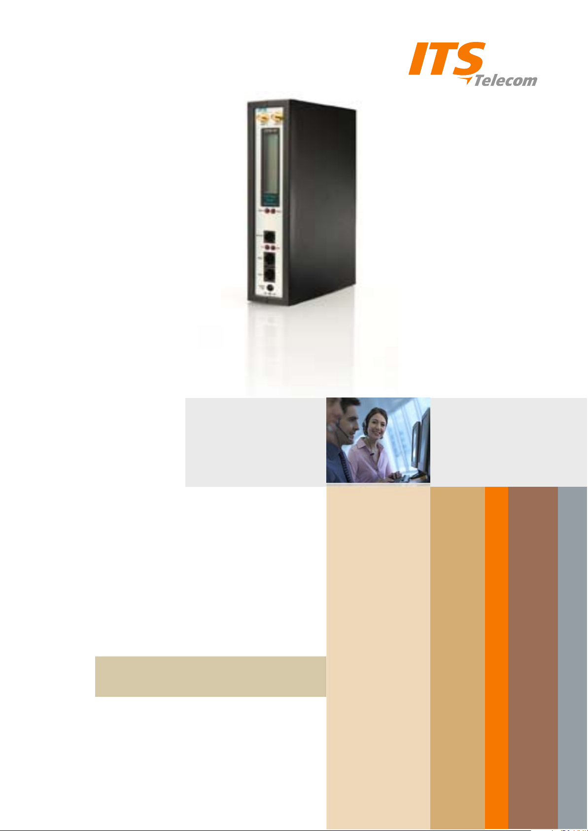
CGW-I
Installation and
Operation Guide
Version 3.18 Release 1
April 2009
Page 2

CGW-I Cellular Gateway
BRI-GSM Interface
Installation and Operation Manual
VERSION 3.18 ED. 1
APRIL, 2009
Page 3

NOTICE
No part of this document may be reproduced or transmitted in any form or by
any means (electronic, photocopying, recording, or otherwise) without the prior
written permission of ITS.
The trademark and service marks of ITS, including the ITS mark and logo, are the
exclusive property of ITS, and may not be used without permission. All other
marks mentioned in this material are the property of their respective owners.
ITS reserves the right to modify the hardware and software described in the
manual without prior notice. However, changes made to the hardware or
software described does not necessarily render this publication invalid.
WARRANTY
In the event this product proves to be defective in workmanship or materials
within a period of one year from date of shipment, ITS will repair or replace the
product at its discretion. Transportation will be the responsibility of the
dealer/distributor.
Under no circumstances shall ITS be liable for consequential or special damages,
loss of revenue or user/dealer expenses arising out of or in connection with the
use or performance of the product, whether based on contract, tort, or any
other legal agreement.
The following shall void the above warranty: malfunctions resulting from fire,
accident, neglect, abuse, or acts of God; use of improper electrical power; or
repair of, tampering with or alteration of the product by anyone other than ITS
authorized personnel.
Page 4

Table of Contents
1. Overview................................................................................. 1
1.1. About this Manual...................................................................................... 1
1.2. Updates In This Version............................................................................ 1
1.3. Main Features ........................................................................................... 2
2. 2. Setting Up Your CGW-I...................................................... 4
2.1. Package Contents..................................................................................... 4
2.2. CGW-I Physical Description...................................................................... 5
2.3. Pre-Installation .......................................................................................... 6
2.4. PBX Trunk Configurations......................................................................... 7
Basic PBX / CGW-I without Synchronization .............................................................7
NT1 / CGW-I Synchronization....................................................................................7
ISDN Extension / CGW-I Synchronization .................................................................8
PBX Proprietary Telephone Interface with NT Card for CGW-I Synchronization ......8
PBX NT / CGW...........................................................................................................9
External Synchronization Feature............................................................................10
2.5. Installation ............................................................................................... 10
Hanging Up the CGW-I ............................................................................................10
SIM Card Insertion ...................................................................................................11
Connecting to the CGW-I .........................................................................................12
Turning on Your CGW-I ...........................................................................................14
2.6. LED Indicators......................................................................................... 14
2.7. LCD Messages........................................................................................ 15
3. 3. CGW-I Manager................................................................ 18
3.1. Setting Up the CGW-I Manager Software ............................................... 18
Installing the CGW-I Manager Software ..................................................................18
GUI Requirements ...................................................................................................18
3.2. General Features .................................................................................... 18
Toolbar .....................................................................................................................18
Status Bar.................................................................................................................19
Help ..........................................................................................................................19
Buttons .....................................................................................................................19
File Menu..................................................................................................................19
View Menu................................................................................................................20
3.3. Communication Menu ............................................................................. 21
Communication Selection ........................................................................................21
Device Selection ......................................................................................................23
Network Settings ......................................................................................................25
Reading Current Parameters ...................................................................................25
Sending Current Parameters ...................................................................................25
CGW-I Cellular Gateway BRI-GSM : Installation and Operation Manual i
Page 5

Setting a Password ..................................................................................................26
3.4. System Menu .......................................................................................... 27
ISDN Settings...........................................................................................................27
System Settings .......................................................................................................28
Toll Restrictions........................................................................................................30
Channel Settings......................................................................................................32
Adjusting the Volume Gain Level.............................................................................33
Operation System Parameters.................................................................................34
Application System Parameters ...............................................................................35
Prepaid Settings.......................................................................................................39
Controlling the CGW-I ..............................................................................................41
3.5. Report Menu............................................................................................ 42
Properties .................................................................................................................42
Statistics ...................................................................................................................43
Reading the CDR (Call Detail Record) ....................................................................45
System Alarms .........................................................................................................46
System Statuses ......................................................................................................48
4. Appendix A: Technical Specifications.............................. 50
CGW-I Cellular Gateway BRI-GSM : Installation and Operation Manual ii
Page 6
1. Overview
Your new CGW-I cellular gateway connects your PBX (Private Branch
eXchange) directly to a GSM cellular network, using the ISDN BRI interface.
By routing your outgoing calls made to cellular numbers through your new
device, you bypass the landline carrier and eliminate excessive
interconnection fees, thus cutting your telephone costs significantly.
The CGW-I offers 2 voice connections and your choice of integrated dualband GSM modules (900/1800, 850/1900 MHz), enabling you to work with
2 different GSM network operators simultaneously.
Also included with your new device is the CGW-I Manager, the BRI-GSM
Utility Program, needed to configure your device with a rich variety of
features that you will learn about as you read through this manual.
1.1. About this Manual
This manual describes the installation, setup and operation of your new
Cellular GateWay for ISDN (BRI interface), which we will now simply refer to
as the CGW-I throughout this manual. It is intended for System Installers and
Administrators and should be read before the installation, setup and
programming of your device.
1.2. Updates In This Version
The following table provides a brief overview of fields that have most
recently been added, moved or removed.
Field Screen Page
Cellular Daily Restart Added to the System Control screen. 41
Remaining Prepaid SIM Time Added to the Statistics screen. 44
Reset Parameters Added to the System Operation screen. 34
SIM Operation Time Replaced by Prepaid Time in the Prepaid
Setting screen (Removed from Statistics
screen).
SIM Operation Time Alarm Functionality updated. 47
39
SIM Setup Moved to the Prepaid Setting screen. 39
Time Unit Moved to the Prepaid Setting screen. 39
DISA Parameters Added to the System Operation screen. 37
Global Time Added to the Prepaid Settings screen. 38
Call Back and Call Through
Features
CGW-I Cellular Gateway BRI-GSM : Installation and Operation Manual 1
Added to the Operation screen. 35
Page 7
Field Screen Page
Call Through instead of Call
back
Add to the Application System parameters
screen
1.3. Main Features
The following table provides a brief overview of the variety of powerful
features available in your new CGW-I.
Feature Functionality
Incoming and Outgoing Call Features
Intelligent Routing
MSN Routing
Call Barring
Return up to 1,500 mobile calls directly to the calling
DDI (Direct Dial-In). CGW-I stores the link between the
dialing extension and the dialed cellular number. When
a missed mobile call is returned, CGW-I recognizes the
Caller ID and routes the caller to the dialer’s extension.
Route incoming cellular calls to default Multi-Subscriber
Number (MSN), such as a specific extension,
Automated Attendant or Voice Mail system.
Dedicate your SIM to handle only incoming calls,
outgoing calls, or both.
Call Diversion
Toll Restrictions
Redirect Call
Call Duration
Disable Channel
Call Back
Call Through
System Management & Monitoring
Full Device Control
Alarms
Automatically reroute incoming calls to an alternate
channel when SIM is busy.
Define which cellular operator prefixes to allow the
CGW-I to call and which ones not to allow.
Override Toll Restrictions and setup a cross-network
connection.
Limit the length of calls to protect you from connections
that are accidentally left open.
Limit calls to channels that have Prepaid Time SIM time.
Automatically returning a call to a caller, who is a
gateway’s database subscriber and providing him a dial
tone for internal and external dialing as PBX extension.
Automatically providing a dial tone to a caller, who is a
gateway’s database subscriber for internal and external
dialing as PBX extension
Configure system parameters and view system status
levels directly from your PC with included user-friendly
Windows-based utility program.
Set thresholds to trigger selected SMS and Email
alarms.
Statistics
CDR
Balance Call Distribution
CGW-I Cellular Gateway BRI-GSM : Installation and Operation Manual 2
View Reception Level and each SIM card’s accumulated
traffic.
Call Detail Recording log for up to 2,500 records.
Evenly distribute call traffic sent to each SIM.
Page 8
Feature Functionality
Configurable Controls & Maintenance
CLIP / CLIR
Display or hide SIM card numbers using Calling Line
Identification Presentation/Restriction setting.
SIM PIN Functionality
Protect each SIM within the CGW-I from unauthorized
use if removed.
Network Lock
Configure your CGW-I to work permanently with only a
specific operator.
Roaming
Allow calls to automatically connect to the strongest
available signal or restrict them to a specific network
operator.
Dialing Mode Support
End of Dialing Digit
Gain Control
Overlap or En Block.
Reduce the time required to connect a dialed number.
Adjust volume levels for both incoming and outgoing
calls on each channel.
2 Voice Channels
Built-in LCD
Each with Integrated GSM Cellular Module
Verify Signal Strength, Operational Status and Cellular
Operator Name to simplify maintenance.
Indicator LEDs
LAN Status (Line and Active), Module Status (2)
Additional system and hardware specifications can be found in Appendix A.
CGW-I Cellular Gateway BRI-GSM : Installation and Operation Manual 3
Page 9
2. 1. Setting Up Your CGW-I
This section lists the full contents of what you have received with your new
CGW-I device, describes how it looks and explains how to physically install it
and verify that it is working properly. Subsequent chapters will explain how
to configure your device using the CGW-I Manager software.
2.1. Package Contents
The following table describes the contents of your device package.
Note:
Should the package be damaged or should items from the packing list be missing,
contact your distributor directly.
Table 1: Contents List
No. Item Qty
1 CGW-I device 1
2 Installation CD with CGW-I Manager Utility Program software and this
Installation and Operation Manual in PDF format
3 Power Supply
(Input: 110VAC, 60Hz or 220VAC, 50Hz)
(Output 9VDC, 13.5W)
4 Antenna (with cable) 2
5 RS-232 cable (RJ-11 – D-Type 9 pin female) 1
6 ISDN Cable (RJ-45 - RJ-45) 2
7 Template for wall mounting 1
8 Screws and plugs necessary for wall mounting 2
1
1
CGW-I Cellular Gateway BRI-GSM : Installation and Operation Manual 4
Page 10
2.2. CGW-I Physical Description
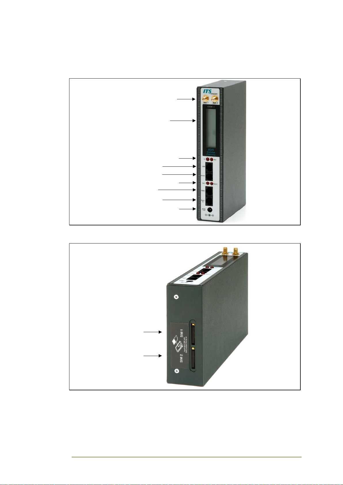
Your device is housed in secure metal box, of which the height is 215mm,
depth 125mm and width 42mm.
Antenna Connectors
Liquid Crystal Display
LAN (LI & ACT) Indicators
LAN Connector
RS-232 Connector
Cellular Engine Indicators
ISDN Connector
Sync-In Connector
Power Supply Connector
Figure 2-1: Front View of the CGW-I Box
SIM 1 Slot
SIM 2 Slot
Figure 2-2: Bottom View of the CGW-I Box
CGW-I Cellular Gateway BRI-GSM : Installation and Operation Manual 5
Page 11

2.3. Pre-Installation
Your CGW-I device contains a GSM engine. It therefore needs a SIM card
from the local GSM network provider. Its registration to the GSM operator is
similar to the registration of a mobile GSM phone.
Note:
Before installing the SIM card, we recommend disabling all Call Forwarding modes (in the
events of busy, absence, unavailability, etc.) and Call Waiting from the GSM operator.
The PIN code requests on the SIM must be disabled to complete the initial
installation. You can disable the SIM with any GSM mobile phone.
If you enable the PIN after installation using your mobile phone, you must
enter the PIN in the Channel Settings screen (see page 33) before you can
make changes to the CGW-I and so that it will work after power up and
reset. If you enter an incorrect PIN three times in the Channel Settings screen
and are locked out by the SIM, you must enter the PUK code to unlock the
SIM.
Note:
To get the PUK code number, you must call your network operator (i.e., local GSM
Service Center). Once you enter the PUK code and unlock the SIM, you must still enter
the correct PIN to use the CGW-I.
CGW-I Cellular Gateway BRI-GSM : Installation and Operation Manual 6
Page 12
2.4. PBX Trunk Configurations
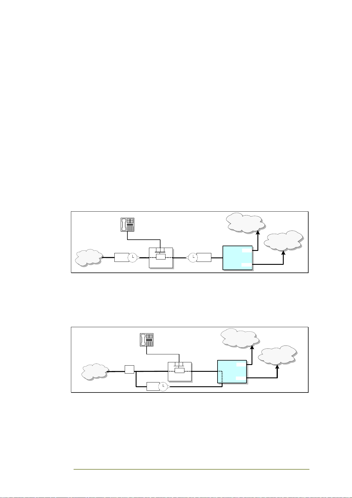
The following configurations describe different PBX Trunk configurations
with TE and NT interfaces which you use to connect the PBX to the PSTN and
CGW. The TE interface always receives an independent time clock from the
NT source. A PBX that receives two different source clocks may experience
communication errors, such as the inability to properly disconnect a
completed call.
The following diagrams offer different solutions to handle a double source
clock situation. In each configuration, a person attached to the PBX dials a
number which is first routed to the PBX LCR (Least Cost Route) to verify the
calling prefix, then routed to the correct interface:
• If the prefix is landline, it creates a connection for the call to leave
via the PSTN interface
• If the prefix is cellular, it routes the call to the CGW-I interface and
the CGW-I connects the call through a cellular network operator.
Basic PBX / CGW-I without Synchronization
GSM
Operator 1
GSM
Operator 2
SIM 1
CGW
SIM 2
PSTN
NT
Source
Clock 1
12
11
1
2
10
3
9
84
75
6
TE
LCR
PBX
TE
12
11
1
2
10
9
84
75
6
Source
3
Clock 2
NT
This diagram describes the simplest PBX/CGW-I configuration where the PBX
is able to select only the source clock is receives from the PSTN as the main
clock and adapt the other NT data information it receives from the CGW.
NT1 / CGW-I Synchronization
GSM
Operator 1
GSM
Operator 2
PSTN
NT TE
U Point Reference
NT1
NT
S Point Reference
Source
Clock
12
11
1
2
10
3
9
84
75
6
LCR
PBX
TE
Synch-In
NT
SIM 1
CGW
SIM 2
CGW-I Cellular Gateway BRI-GSM : Installation and Operation Manual 7
Page 13
This diagram describes an NT1/CGW-I configuration option which can be
used when the PBX requires a single source clock and an NT1 device
connects the PSTN to the PBX. By connecting to the NT interface of the NT1
which sends the source clock to the PBX to the Synch-In interface of the
CGW, the CGW-I is able to ensure synchronization of the NT source clock it
sends to the PBX by using the source clock that the PSTN sends to the PBX.
ISDN Extension / CGW-I Synchronization
ISDN
Phone
ISDN Cable
ISDN
Terminal
Adaptor
Source
Clock
TE
12
11
10
9
84
75
GSM
1
2
3
6
Operator 1
GSM
PSTN
NT
TE
NT
NT
LCR
PBX
TE
Synch-In
NT
Operator 2
SIM 1
CGW
SIM 2
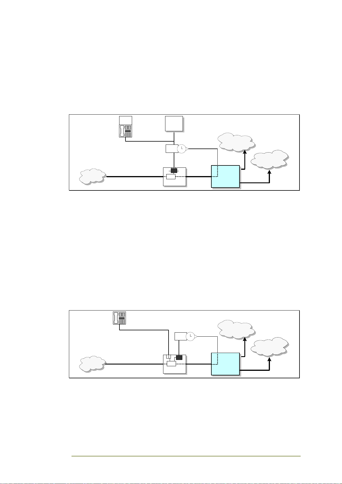
This diagram describes an ISDN Extension/CGW-I configuration option which
can be used when the PBX requires a single source clock and the PBX has an
NT interface to an extension telephone or terminal adaptor. It is common
when the communication between the PSTN and PBX is over a direct PRI
connection and there is no NT1 for synchronization. By connecting from the
ISDN cable leaving the NT interface of the PBX to the Synch-In interface of
the CGW, the CGW-I is able to ensure synchronization of the NT source
clock since it sends back the same source clock it received from the PBX.
Utilizing the existing cable also lets you avoid using additional ISDN BRI
resources (i.e., B1 or B2).
PBX Proprietary Telephone Interface with NT Card
for CGW-I Synchronization
GSM
PSTN
Proprietary Connection
NT
TE
LCR
PBX
Source
Clock
NT
NT
12
1
11
2
10
9
84
75
6
TE
3
Synch-In
NT
Operator 1
GSM
Operator 2
SIM 1
CGW
SIM 2
CGW-I Cellular Gateway BRI-GSM : Installation and Operation Manual 8
Page 14
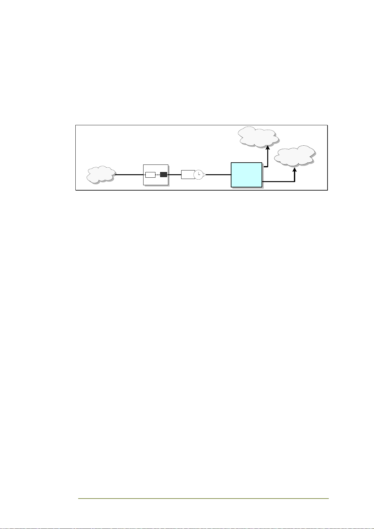
This diagram describes a configuration where the PBX uses a proprietary
interface connection to the different telephone extensions. Therefore, the
PBX requires a special NT card to create an additional NT interface leaving
the PBX which will provide the source clock. By connecting the new PBX NT
interface to the Synch-In interface of the CGW, the CGW-I is able to ensure
synchronization of the source clock it sends back to the PBX.
PBX NT / CGW
GSM
Operator 1
GSM
Operator 2
SIM 1
CGW
SIM 2
PSTN
NT
TE
LCR
PBX
NT
NT
Source
Clock
12
11
1
2
10
3
9
84
75
6
TE
CGW-I Cellular Gateway BRI-GSM : Installation and Operation Manual 9
Page 15

This diagram describes a simple PBX NT/CGW-I configuration where the PBX
provides a direct NT interface to the TE interface of CGW. Synchronization is
automatically ensured in this configuration since the single connection to the
CGW-I includes the source clock sent by the PBX.
External Synchronization Feature
If you set up your CGW-I with a configuration that uses the Synch-In
interface to ensure synchronization, you must enable the External
Synchronization feature in the ISDN Settings window. When this feature is
enabled, the CGW-I time clock becomes a “slave” to the external time clock
since it takes the clock it receives from the NT source. When this feature is
disabled, the CGW-I becomes the “Master” of the time clock it sends to the
PBX. You should also disable External Synchronization when the CGW-I
connects to a TE interface. To learn how to set enable the External
Synchronization feature, see page 27.
2.5. Installation
Setting up your CGW-I requires at least one SIM card from the local GSM
network provider and a few simple connections between the CGW-I box and
the following:
• RS-232 (Setup)
• Antenna
• Communication line
• Synch-In line (Optional)
• ISDN trunk interface of your PBX fxo
• Power supply.
The following sections describe how to make all these connections.
Hanging Up the CGW-I
You can hang the CGW-I on the specially designed mounting plate or
directly on the wall.
To hang the CGW-I directly on the wall, first drill holes according to the
enclosed template, then drill in screws and hang the device from them.
CGW-I Cellular Gateway BRI-GSM : Installation and Operation Manual 10
Page 16
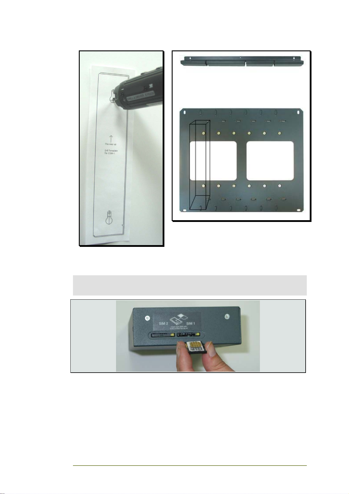
Drill Template Mounting Plate and Antenna Holder
SIM Card Insertion
CAUTION:
To avoid damage to your CGW-I device, you should disconnect the 9V adapter from the
electric power-outlet when inserting or removing the SIM card.
The figure above can be used as guideline for the following steps:
1. Hold the device in your hands with the display pointed to your
right and the SIM insertion slot at the bottom of the unit towards
you.
2. Use a pointed pen or screwdriver to push the round yellow SIM
release lever. The SIM card tray should move out towards you.
CGW-I Cellular Gateway BRI-GSM : Installation and Operation Manual 11
Page 17
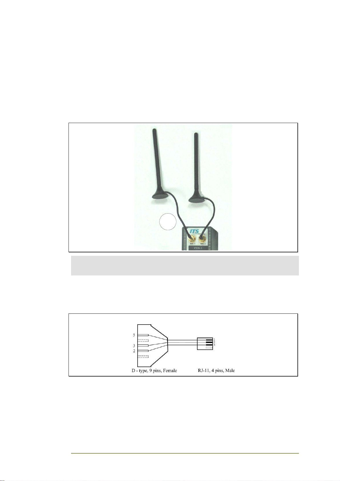
3. Take out the tray. You will see that the SIM card will fit in the tray
only one way.
4. Carefully place the tray with the SIM card back into the slot and
slide it in with the SIM card contacts facing up.
Connecting to the CGW-I
n
Screw in the antenna cable(s) to the antenna to the Ant. 1 or Ant. 2
connector.
1
Note:
If you are only using one SIM card, make sure that the channel number is the same as
the antenna connector you are using (i.e., SIM1 uses Ant.1).
Connecting the Communication Lines
The following diagrams show the different cables that connect to your
device.
RS-232 Cable
CGW-I Cellular Gateway BRI-GSM : Installation and Operation Manual 12
Page 18
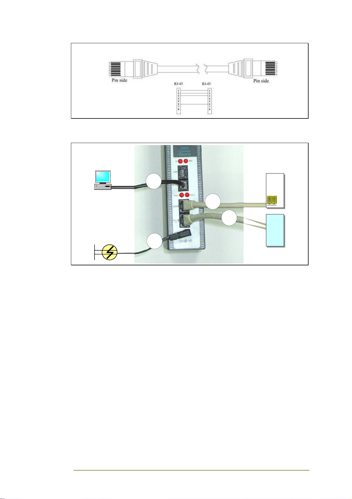
RJ-45 Cable
The following diagram shows how to connect the different cables to your
device.
PC
9VDC 1.5A
Power Supply
2
5
PBX
3
4
NT
CGW-I Cellular Gateway BRI-GSM : Installation and Operation Manual 13
Page 19
o Connect the RS-232 cable from a PC to the RS-232 interface of the
CGW-I.
Note:
Communication with the CGW-I can be done over either the RS-232 interface or LAN
connection. Even you plan to communicate with the CGW-I over a LAN, you must
first connect the RS-232 cable to define the network parameters and complete the
initial setup
p Connect the RJ-45 cable from the PBX to the ISDN interface of the
CGW-I.
q If you need to synchronize the CGW-I time clock, connect the RJ-45 cable
from the NT interface to the Synch-In interface of the CGW-I.
r Connect the supplied 9VDC 1.5A power converter cable to the CGW-I
power supply connector.
If you want to communicate over a LAN, once you have completed steps 1-5
you must remove the RS-232 cable and connect an RJ-45 Cable from your
LAN to the LAN interface of the CGW-I.
Turning on Your CGW-I
CAUTION:
To avoid damage to your CGW-I device, the 9V adapter should be disconnected from the
electric power-outlet when inserting or removing the SIM card.
After you connect the supplied 9VDC power supply converter cable into the
9VDC port of the CGW-I device plug it into the appropriate power supply. A
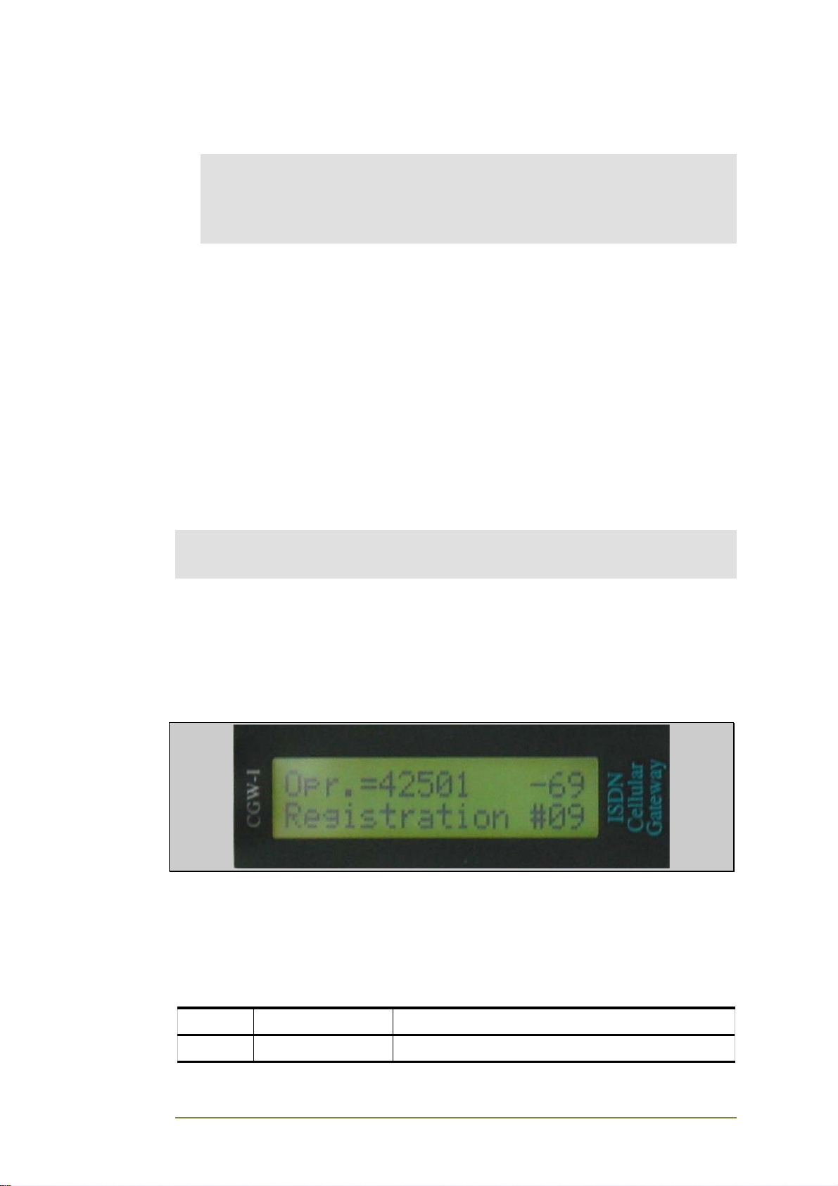
message should now appear on your CGW-I LCD, indicating that the device
is now working. For a description of the different messages, please see LCD
Messages on page 15.
You are now ready to configure your new CGW-I device.
2.6. LED Indicators
Your device contains 4 LEDs that indicate the status of communications
going through the device. The following table describes the LEDs and their
purpose.
Name LED Status
Li On LAN cable is connected to CGW-I
CGW-I Cellular Gateway BRI-GSM : Installation and Operation Manual 14
Page 20
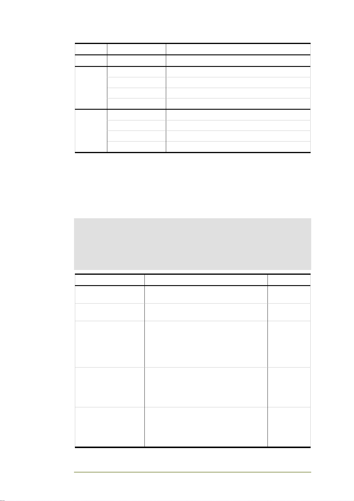
Name LED Status
Act Flashing Receiving or transmitting call through the LAN
Stat. 1
Stat. 2
On Registering
Off Problem
Fast blinking During call process or connection
Slow blinking Idle
On Registering
Off Problem
Fast blinking During call process or connection
Slow blinking Idle
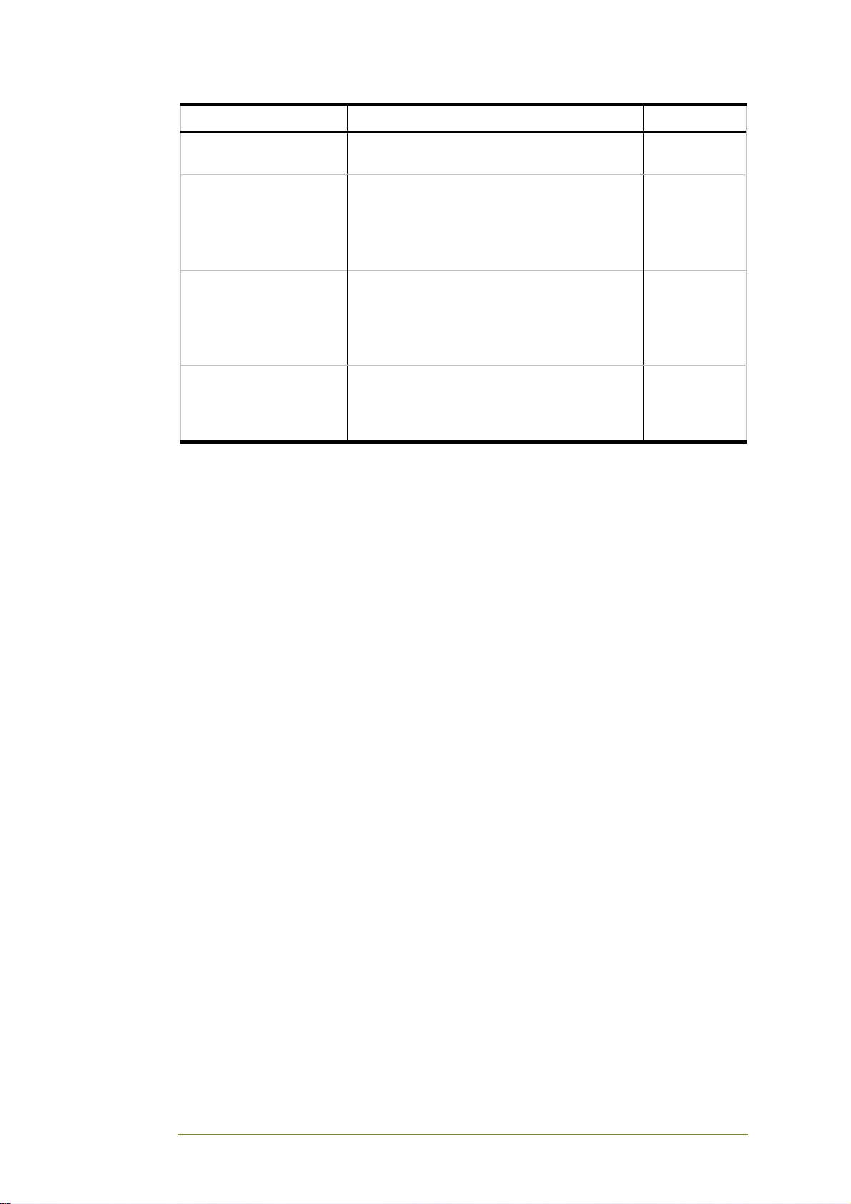
2.7. LCD Messages
The following table describes the LCD messages, which can occur during the
operation of your device. Also included are the actions that are needed. The
purpose of the display is to help the installer and administrator to quickly
make your device operational.
Notes:
A message appears on the row relevant to the specific channel: Row 1 refers to
Channel 1 and Row 2 refers to Channel 2. ISDN Errors are relevant to the whole
device and both channels.
The number of the operator can be between 5-7 digits
The reception level can be from 2-3 digits.
LCD Messages Description Action
Version Number During power on, the version number is
displayed until the device begins registration.
Registration #XX During initial registration, displays the current
step in the process.
Opr. =XXXXXXX -XXX During an idle state, the number of the
operator appears together with the reception
level.
Number is displayed when the Number value
is selected in LCD Operator Display (see
page 29).
Operator NoSig If there is no signal, the name of the operator
appears with NoSig.
Operator name is displayed when the Name
value is selected in LCD Operator Display
(see page 29).
Opr. =XXXXXXX NoSig If there is no signal, the number of the
operator appears with NoSig.
Operator Number is displayed when the
Number value is selected in LCD Operator
Display (see page 29).
Check
antenna
location. See
Reception
Level, pg 48.
Check
antenna
location. See
Reception
Level, pg 48.
CGW-I Cellular Gateway BRI-GSM : Installation and Operation Manual 15
Page 21

LCD Messages Description Action
No Name NoSig If there is no signal and the name of the
operator is not available.
No Name is displayed when the Name value
is selected in LCD Operator Display (see
page 29).
No Num. NoSig If there is no signal and the number of the
operator is not available.
No Number is displayed when the Number
value is selected in LCD Operator Display
(see page 29).
Calling -XXX When an outgoing call is being made,
Calling and the 2-3 digit signal level is
displayed.
Ring At Dst –XXX When an outgoing call is ringing at the
destination number, Ring At Dst and the 2-3
digit signal level are displayed.
Ringing –XXX When an incoming call is ringing, Ringing
and the 2-3 digit signal level are displayed.
Connected -XXX When a call is connected, Connect and the
2-3 digit signal level are displayed.
Disconnecting –XXX When a call is being disconnected,
Disconnecting and the 2-3 digit signal level
are displayed.
Check
antenna
location. See
Reception
Level, pg 48.
Check
antenna
location. See
Reception
Level, pg 48.
Busy -XXX When an outgoing call is dialed and the
number is busy, Busy and the 2-3 digit signal
level are displayed.
Drawer Open The SIM drawer is open. Close the
drawer
ISDN Error
No Sync
There is a synchronization error. Check
physical cable
from NT
source to
Synch-In port.
ISDN Error
Interface Failure
ISDN Error
No Link
The is an error with the ISDN interface
communication.
Reset the
ISDN.
There is no link to the PBX. Check
physical cable
from NT
source to the
device.
Error: Pin Code Displayed when you enter the incorrect SIM
code in the GUI.
Enter the
correct PIN or
disable the
PIN code.
Error: Puk Code When an incorrect PIN is entered and the
card is locked, you must call the network
operator to get the correct PUK code to
unlock the code.
Call your
network
operator to
get the PUK
code.
CGW-I Cellular Gateway BRI-GSM : Installation and Operation Manual 16
Page 22
LCD Messages Description Action
Error: No SIM The SIM card is not inserted. Insert a GSM
SIM card.
Operator Close The device is performing a Gentle Close on
this channel.
Name is displayed when the Name value is
selected in LCD Operator Display (see page
29).
Opr. = XXXXXXX Close The device is performing a Gentle Close on
this channel.
Operator Number is displayed when the
Number value is selected in LCD Operator
Display (see page 29).
No SIM Time The credit on the SIM card is finished. Insert a new
SIM card or
perform Reset
Parameters.
CGW-I Cellular Gateway BRI-GSM : Installation and Operation Manual 17
Page 23
3. 2. CGW-I Manager
The CGW-I Manager is a utility program that lets you set your device’s
configuration parameters and supervise how it is being used.
The following sections describe the different CGW-I Manager menus and
screens, as well as the various buttons you need to click to control these
screens and the send information.
3.1. Setting Up the CGW-I Manager
Software
Installing the CGW-I Manager Software
1. Insert the CGW-I Manager CD in the CD-ROM drive of your PC.
The CD should run automatically.
2. At the end of each stage of installation, click the Next button to
continue.
GUI Requirements
CGW-I Manager is designed to run on screens set to 1024 x 768 resolution.
Any other setting may not display the program properly.
3.2. General Features
This section describes the various elements and functions that are common
to many of the CGW-I Manager screens or to Windows:
• Toolbar and Status bar
• Help
• Standard buttons
• Basic file saving and printing functionality
Toolbar
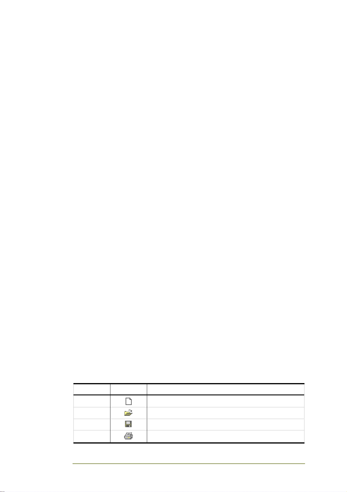
The following function buttons appear on the main screen’s toolbar:
Name Button Function
New
Open
Save
Print
CGW-I Cellular Gateway BRI-GSM : Installation and Operation Manual 18
Creates a new device configuration file.
Opens an existing device configuration file.
Saves the open device configuration file.
Prints the contents of the open device configuration file.
Page 24
Status Bar
The Status bar at the bottom of the Main screen displays important
messages about the current screen or how to get further Help.
Help
CGW-I Manager comes with context sensitive Help which describes each
field and button.
• To view Help for a window, press the screen’s Help button.
• To view Help for a specific field, select it and press the F1 button.
• To view the main Help window, select Help @ Help Topics.
From any specific Help page, clicking the Contents tab will also
display the main Help window.
Buttons
The following table describes the different buttons found throughout the
various CGW-I Manager screens.
Button Function
OK Saves any changes you have made and then closes this window.
Apply Sends the changes made on this window to your device, but without
closing the window. If this is the first time you are sending parameters
to your device since login, a password is required.
Cancel Closes this window.
Close Closes this window and retains the changes you have made.
Help Displays all Help topics.
File Menu
The following table describes the different File menu options.
Button Function
New Creates a new configuration file, based on the default
parameters.
Toolbar shortcut: New button.
Open Opens an existing configuration file.
Toolbar shortcut: Open button.
Save Saves the current configuration file.
Toolbar shortcut: Save button.
Save As Saves the current configuration file with a different name and/or
in a different directory.
Page Setup Defines the printer paper setup.
Toolbar shortcut: Print button.
CGW-I Cellular Gateway BRI-GSM : Installation and Operation Manual 19
Page 25
Button Function
Print Configuration Gives a choice of printing options: All, Control Parameters, Toll
Restriction, Statistics.
Print Preview Shows a preview of the information to be printed.
Print Prints the contents of the current configuration file.
Recent File Shows the most recently used configuration files.
Exit Closes the program.
View Menu
The following table describes the different options listed on the View menu.
Button Function
Toolbar Select the Toolbar option (i.e., checked) to display the Toolbar
at the top of the screen.
Status Bar Select the Status Bar option (i.e., checked) to display the Status
bar at the bottom of the screen.
CGW-I Cellular Gateway BRI-GSM : Installation and Operation Manual 20
Page 26
3.3. Communication Menu
The Communication menu lists the following options for setting up
communication between the CGW-I Manager and your device:
• Communication Selection
• Network Settings
• Read Parameters
• Send Parameters
• Password
The following sections describe each option and the windows that they
open.
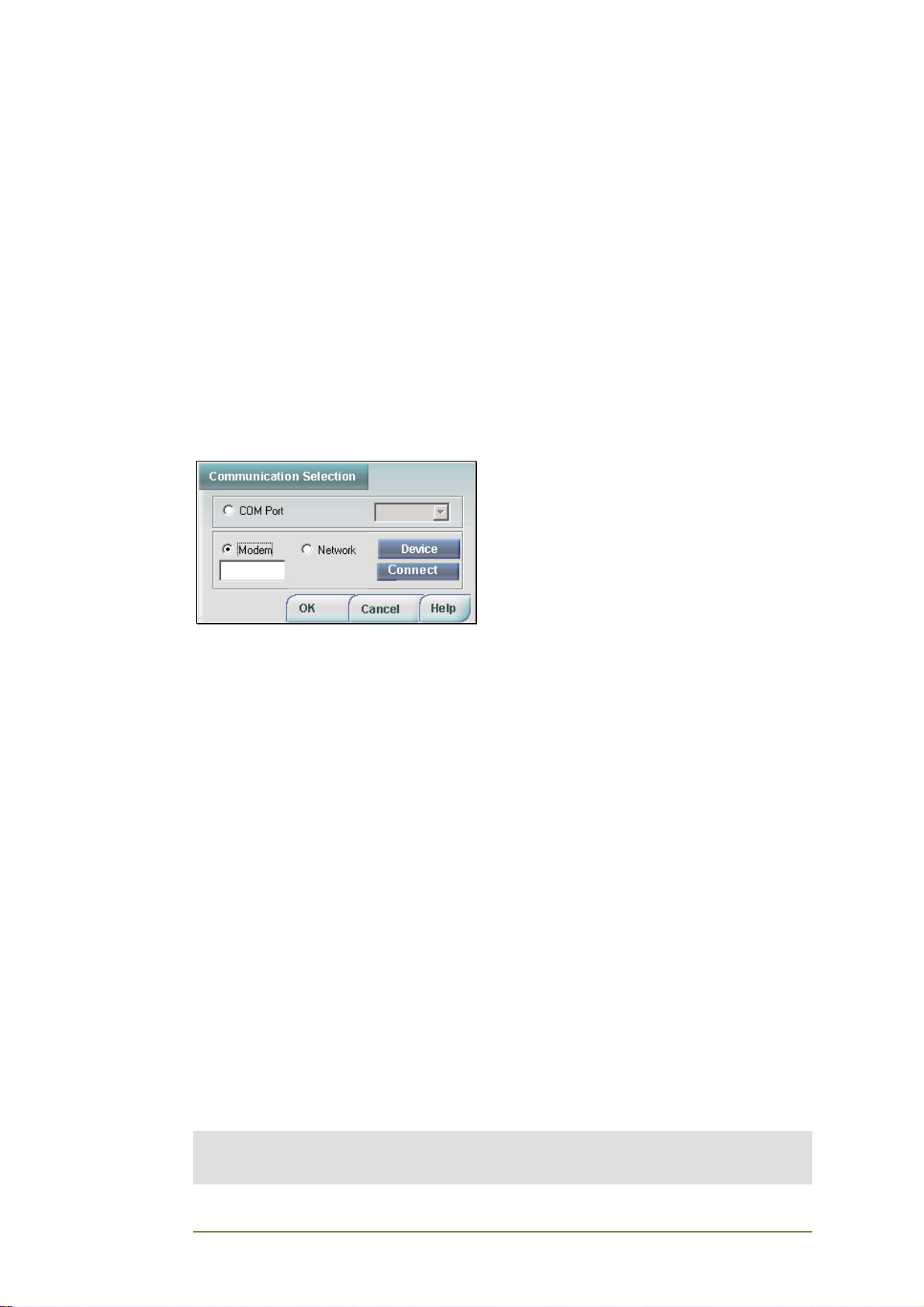
Communication Selection
The Communication Selection window lets you set up a communication
channel from your PC to your CGW-I. You can choose from the following
connections: COM Port, Network or Modem.
To open the Communication Selection window:
From the Main menu, select: Communication > Communication Selection.
COM Port
The COM Port option lets you communicate with your device through the
Serial port of your PC.
To set up a COM Port connection:
1. Click the COM Port option
2. Select the port that connects your computer to your device from
the COM Port list.
3. Click OK to update the CGW-I Manager of your new
communication selection.
Modem
The Modem option lets you communicate with your CGW-I from a PC using
a modem.
Note:
E-mail system alarms that you set can only be sent if your CGW-I is connected to a LAN
with an IP connection.
CGW-I Cellular Gateway BRI-GSM : Installation and Operation Manual 21
Page 27

To connect to your device using a modem:
1. Click the Modem option to enable the Device button.
2. Do one of the following:
• Enter the telephone number of the CGW-I in the modem field.
Note:
The CGW-I device you are connecting to and its telephone number must
already be defined in the Device Database. See the Device Selection
section for more details on defining your CGW-I device.
• Click the Device button to open the Device Selection window,
select the CGW-I device you are connecting to, then click OK
to accept your choice and close the Device Selection window.
Note:
Since you are connecting with a modem, a phone number of the CGW-I
must be defined. See the Device Selection section for more details on
defining a modem.
3. The CGW-I modem’s phone number appears in the Modem field
of the Communication Selection window. Click the Connect
button to dial the modem and initiate communication.
4. Click OK to update the CGW-I Manager of your new
communication selection.
Network
The Network option lets you communicate with your device over a network.
To set up a Network connection:
1. Click the Network option to enable the Device button, then click
the Device button to open the Device Selection window.
2. Select your CGW-I device, then click OK to accept your choice and
close the Device Selection window.
3. Click OK to update the CGW-I Manager of your new
communication selection.
CGW-I Cellular Gateway BRI-GSM : Installation and Operation Manual 22
Page 28
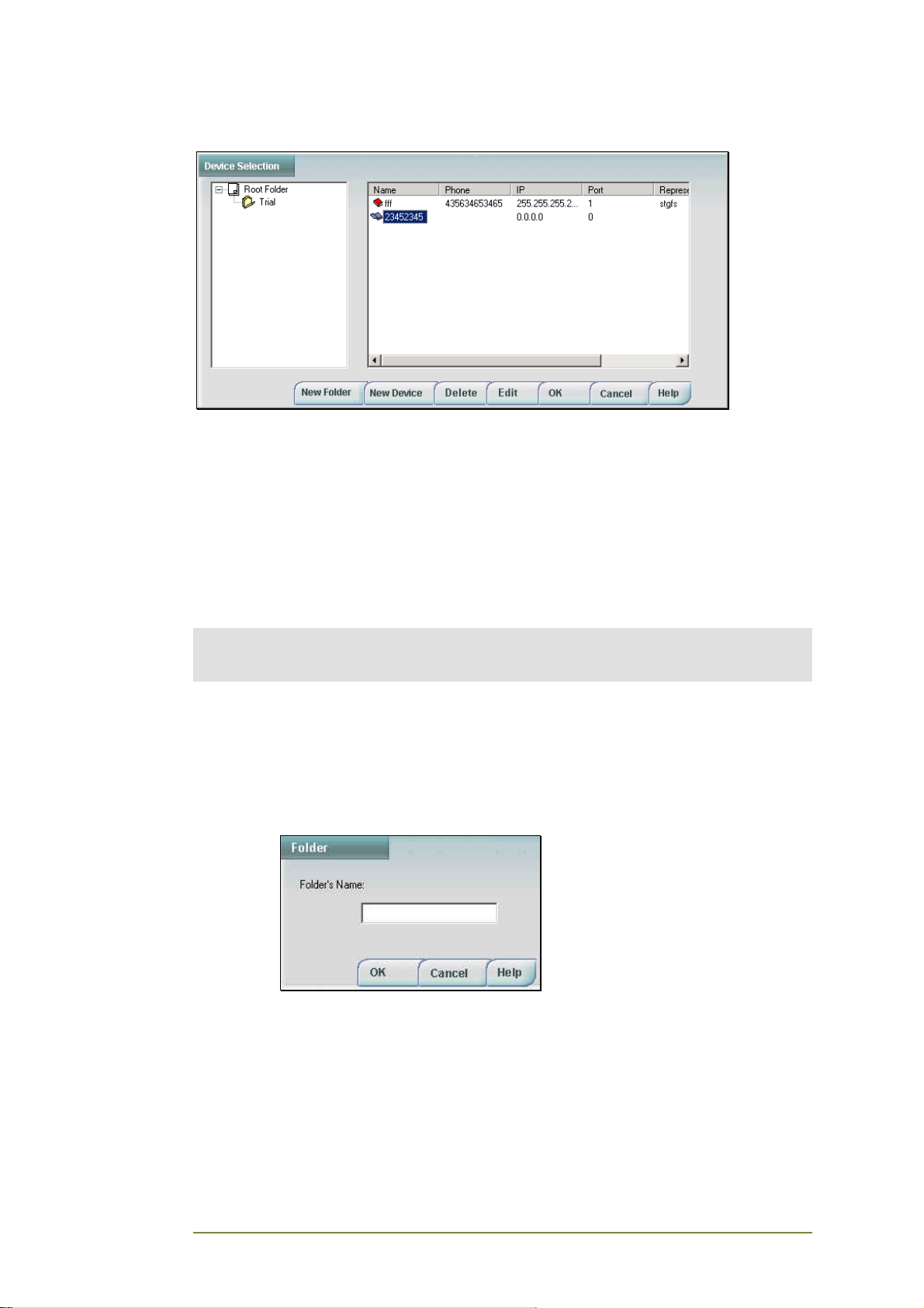
Device Selection
The Device Selection window displays the Device Database showing a tree
structure of the different CGW-I devices that you may want to connect to
from a PC. For example, if you are installing multiple CGW-I devices in
different locations, you may want to create a different branch (i.e., folder)
for each location. Each branch will store the different CGW-I devices at the
specific location.
To open the Device Selection window:
Click the Device button in the Communication Selection window.
Note:
If you select either Network or Modem to communicate with your CGW-I, the network
administrator must add the contact information of the CGW-I unit to the Device Database.
Since the Root branch cannot contain a device, you must first create a new
folder that you will use to store a device.
To begin a new branch in the database tree:
1. Click the New Folder button to open the Folder window to enter
the folder’s name.
2. Enter the new folder’s name and click OK. The folder now appears
as a new branch in the Device Database tree.
CGW-I Cellular Gateway BRI-GSM : Installation and Operation Manual 23
Page 29
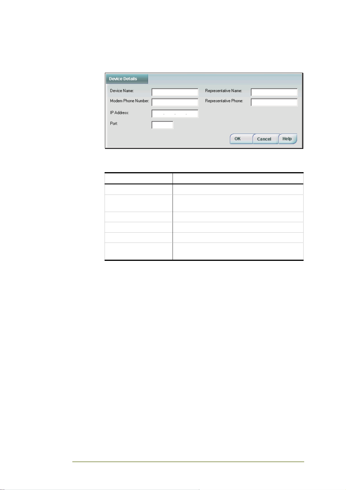
To add a new device to a folder:
1. Go to the folder you are creating the device then click the New
Device button. The Device Details window opens.
2. Define the settings required to communicate with your CGW-I
device. Enter the following parameters:
Field Parameter
Device Name Name of your device
Modem Phone Number Phone number if connecting to the device with a
IP Address IP Address of your device
Port Number Port Number of your device
Representative Name Contact person responsible for this device
Representative Phone Phone number of the contact person
To delete a device or folder:
1. Select the folder or device you want to delete then click the Delete
button.
2. If you are deleting a folder that has devices, you will see a warning
that they will all be deleted. If you click Yes to delete it, the folder
and all its contents are erased from the database.
To edit a folder name:
1. Select the folder name you want to edit, then click the Edit
button. The Folder name window appears.
2. Change the name of the folder and click OK.
modem
responsible for this device
To edit a device’s details:
1. Select the device you want to edit, then click the Edit button. The
Device Details window appears.
2. Change the details of the device and click OK.
CGW-I Cellular Gateway BRI-GSM : Installation and Operation Manual 24
Page 30
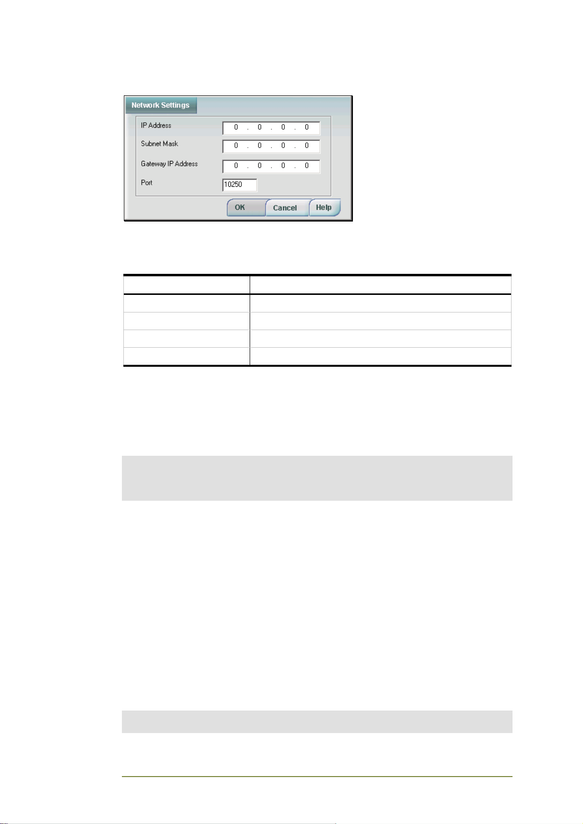
Network Settings
If your CGW-I device is connected to the network, the Network Settings
window lets you define its address so that you can communicate with it
remotely over TCP/IP.
Field Parameter
IP Address IP Address of your device in the network
Subnet Mask Subnet Mask of your device in the network
Gateway IP Address IP Address of the network gateway
Port Port used by your device
Reading Current Parameters
To download all configuration parameters from the connected CGW-I,
select: Communication @ Read Parameters, then click OK to read the
parameters.
Notes:
You must be connected to the device to read parameters. A password must be entered
before you can read parameters for the first time (default=1234) during a connection to a
specific CGW-I device. It is recommended that you change the password.
A gray bar will show the loading progress, followed by a message indicating
whether the action was successful or not. If it was, the different CGW-I
Manager screens now display all the current parameters of the connected
CGW-I.
Sending Current Parameters
You can make changes to the parameters offline, without being connected
to the device, but they will not be uploaded until you are connected. If you
are connected and click the Apply button, any changes you have made on
the open screen are sent to the device if you are connected.
To upload the configuration parameters that you may have changed and are
currently displayed on the different CGW-I Manager screens, select:
Communication @ Send Parameters.
Note:
You must be connected to the device to send parameters. A password must be entered
CGW-I Cellular Gateway BRI-GSM : Installation and Operation Manual 25
Page 31
the first time you make a connection to a specific CGW-I device before you can upload
parameters to it.
A gray bar will show the sending progress, followed by a message indicating
whether the action was successful or not.
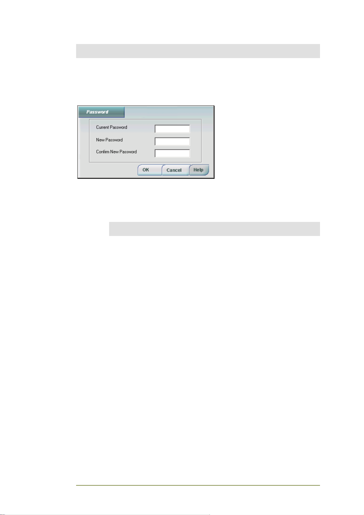
Setting a Password
A password must be filled in before reading or sending parameters.
To change the administrator’s password:
1. Enter the Current Password.
Note:
Password is not case sensitive. Entry is shown in asterisks (******).
2. Enter the New Password for the connected CGW-I. The password
can be up to 16 characters.
3. Re-enter the new password for confirmation. A message will
appear indicating if the Password has been changed successfully
or not.
CGW-I Cellular Gateway BRI-GSM : Installation and Operation Manual 26
Page 32
3.4. System Menu
The System menu lists the following options for configuring your CGW-I.
• ISDN Setting
• System Settings
• Channel Settings
• System Operation
• Prepaid Settings
• Control
The following sections describe each option and the windows that they
open.
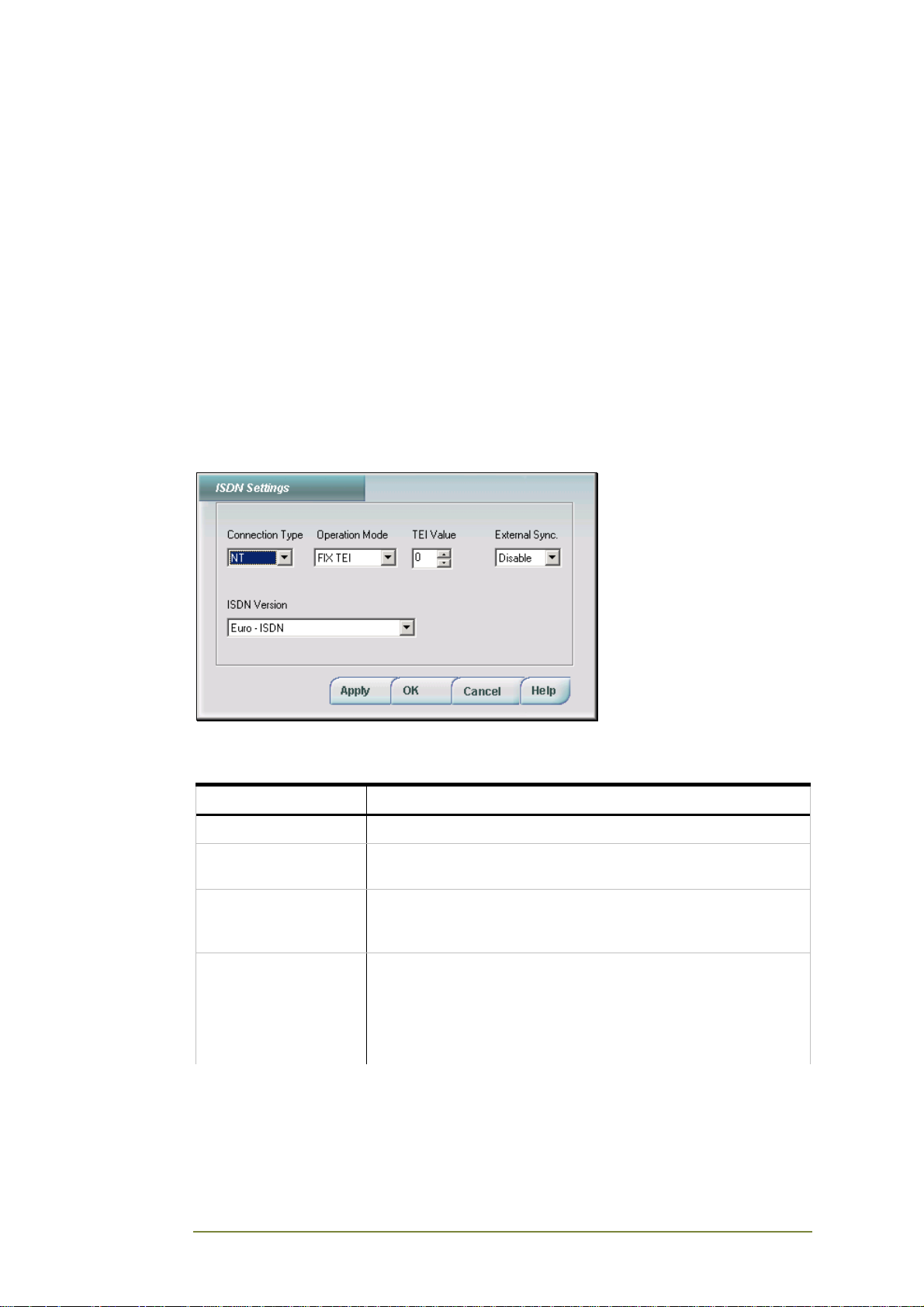
ISDN Settings
The ISDN Settings window lets you set the parameters of the ISDN
connection to your CGW-I device. Enter the following parameters:
Field Parameter
Connection Type Select the BRI interface: NT or TE.
Operation Mode Select either FIX TEI or AUTO TEI. When in AUTO TEI, the
TEI value is not relevant.
TEI Value Enter TEI (Terminal Equipment Identifier) value: 0-63. The
TEI value should only be entered when the Operation Mode is
PTP.
External
Synchronization
Enable when synchronization is done by another device which
connects to the Synch-In port of the CGW-I.
Disable when the CGW-I connects to a TE interface or the
CGW-I Synch-In port is not used.
For more details on external synchronization, see page 10.
CGW-I Cellular Gateway BRI-GSM : Installation and Operation Manual 27
Page 33
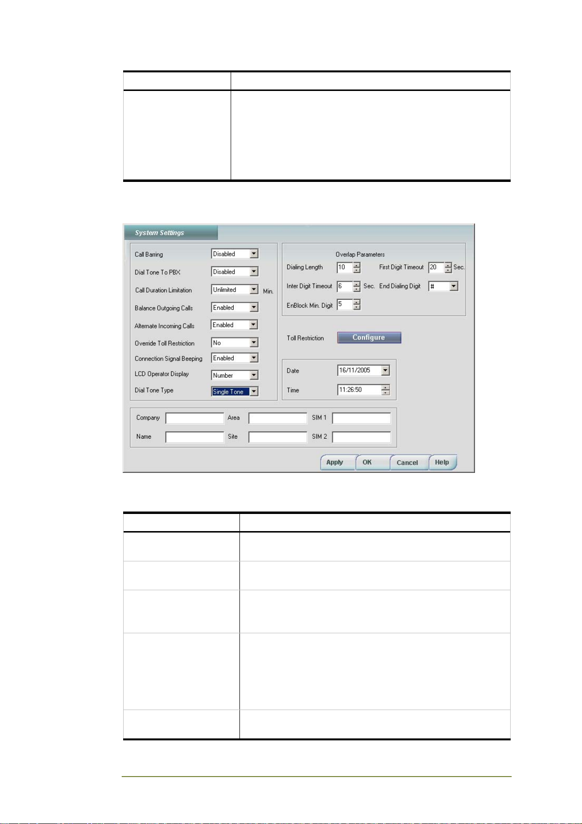
Field Parameter
ISDN Version Select current ISDN-BRI version. Choose from:
• Euro-ISDN (default)
• Euro-ISDN – In Bound DTMF Dialing
• Euro-ISDN – France
• 1TR6 – Germany
• Euro-ISDN – Germany
System Settings
The System Settings window lets you set the parameters for calls going
through your CGW-I device. Enter the following parameters:
Field Parameter
Call Barring Prevents SIM from accepting incoming calls or outgoing
calls. Select Disable to allow all calls.
Dial Tone to PBX Enables or disables the device’s dial tone heard on an
extension phone.
Call Duration Limitation Limits the length in minutes of outgoing calls to protect you
from connections that are accidentally left open.
15-90 minutes in steps of 15 minutes each or unlimited.
Balance Outgoing Calls The device attempts to equally distribute the number of
outgoing calls sent to each SIM by alternating calls sent to
each one when both SIMs are idle. If one SIM is busy, the
call is automatically routed to the available card.
Note: The CGW-I will not balance calls between channels if
Toll Restrictions setting restrict calls to specific SIMs.
Alternate Incoming
Calls
The device alternates routing of incoming calls received by
each SIM between the two ISDN channels.
CGW-I Cellular Gateway BRI-GSM : Installation and Operation Manual 28
Page 34
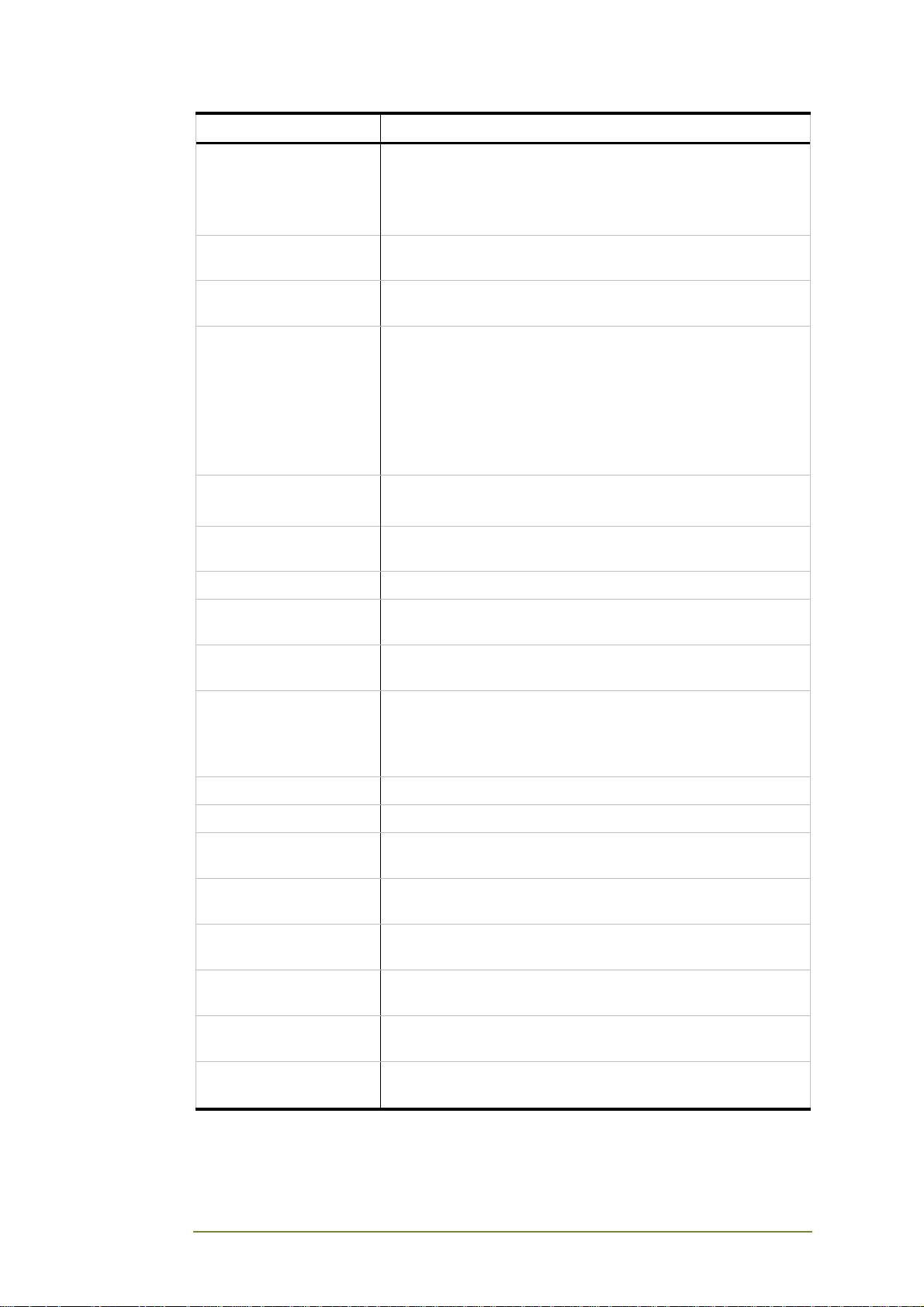
Field Parameter
Override Toll Restriction Sets up a cross-network connection if the channel is busy,
regardless of what is defined as the Toll Restrictions.
Yes routes a call to the second channel.
No does not route a call to the second channel.
Connection Signal
Beeping
Sounds a tone from end of dialing until mobile phone begins
ringing.
LCD Operator Display Number or Name. Sets the LCD display to show either the
number or the name of the network operator.
Dial Tone Type Defines a type of the provided dial tone in DISA mode.
Available options: No Dial Tone, Single Tone, Dual Tone,
where:
No Dial Tone – dial tone disabled
Single Tone – one tone 400 Hz generated signal
Dual Tone – two tones 350 Hz and 400 Hz generated
signal
Dialing Length Defines the maximum number of digits for external calls.
Range: 6-14 digits.
Inter-Digit Timeout Number of seconds (1-60) device will wait between digits
before dialing entered number.
EnBlock Minutes Digit Minimum number of digits in EnBlock for call initiation.
First Digit Timeout Number of seconds (1-60) device will wait between first and
second digit before dialing entered number.
End Dialing Digit Overrides all dialing timeouts to immediately dial the
entered number.
Toll Restriction Defines which cellular operator prefixes to allow the device
to call and on which channel, or which ones not to allow.
Click the Configure button to define the calling prefixes.
For more details, see Toll Restriction (page 29).
Date Sets current date used by device.
Time Sets current time used by device.
Company Defines name of company. Displayed in Customer Details
on opening screen.
Name Defines name of device. Displayed in Customer Details on
opening screen.
Area Defines area where device sits. Displayed in Customer
Details on opening screen.
Site Defines site of device. Displayed in Customer Details on
opening screen.
SIM 1 Number of SIM 1. Displayed in Customer Details on
opening screen.
SIM 2 Number of SIM 2. Displayed in Customer Details on
opening screen.
CGW-I Cellular Gateway BRI-GSM : Installation and Operation Manual 29
Page 35
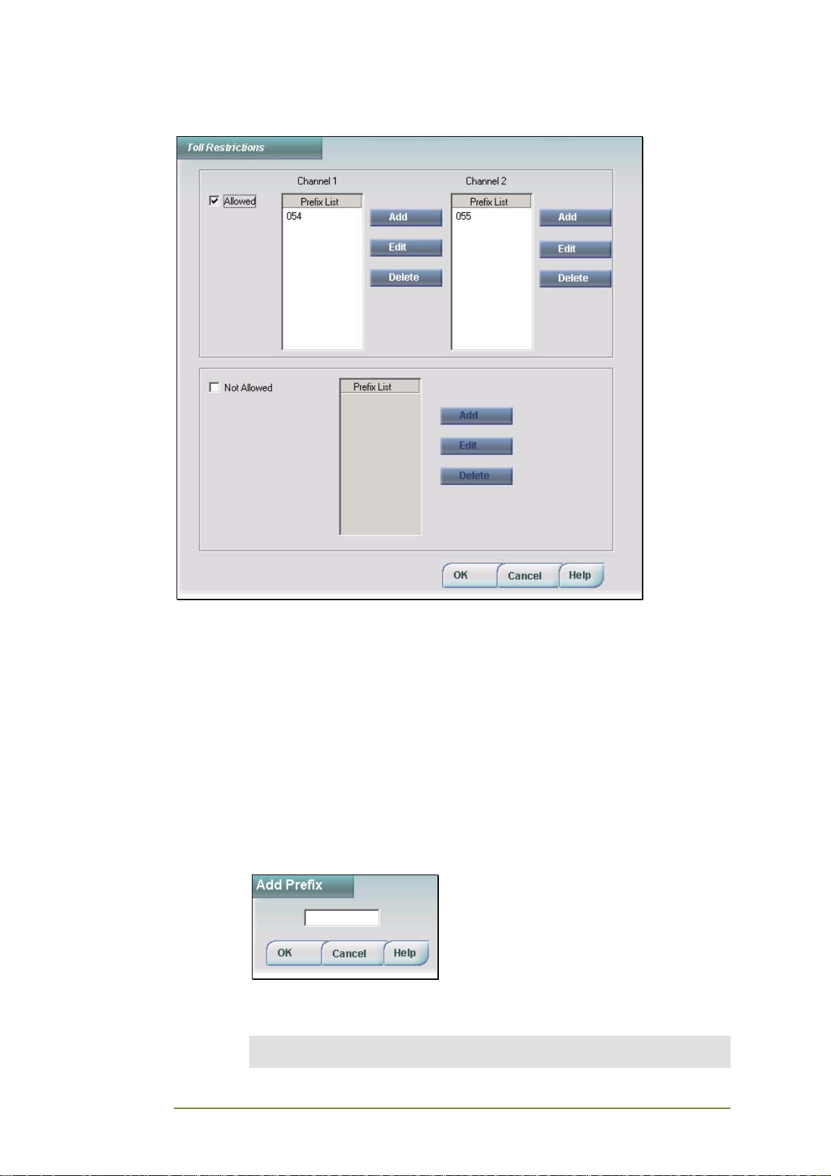
Toll Restrictions
The Toll Restriction window defines up to 22 different cellular operator
prefixes that will either be permitted or forbidden to go through the CGW-I
device and the channel through which they will be routed. Each prefix can
be up to 7 digits long. Each Allowed list can hold up to 20 prefixes. The Not
Allowed list can hold up to 12 prefixes.
To allow a specific prefix to be used on a specific channel:
1. Check the Allowed checkbox to enable both Allowed Prefix List
panes. They display the cellular operator prefixes your device can
call on each channel.
Click the Add button for the channel you want to use for calls
beginning with this prefix. The Add Prefix window is displayed.
2. Enter dialing prefix, then click OK. The number is added to the
channel’s prefix list.
Note:
Prefixes should not conflict with any existing PBX LCR Rules.
CGW-I Cellular Gateway BRI-GSM : Installation and Operation Manual 30
Page 36
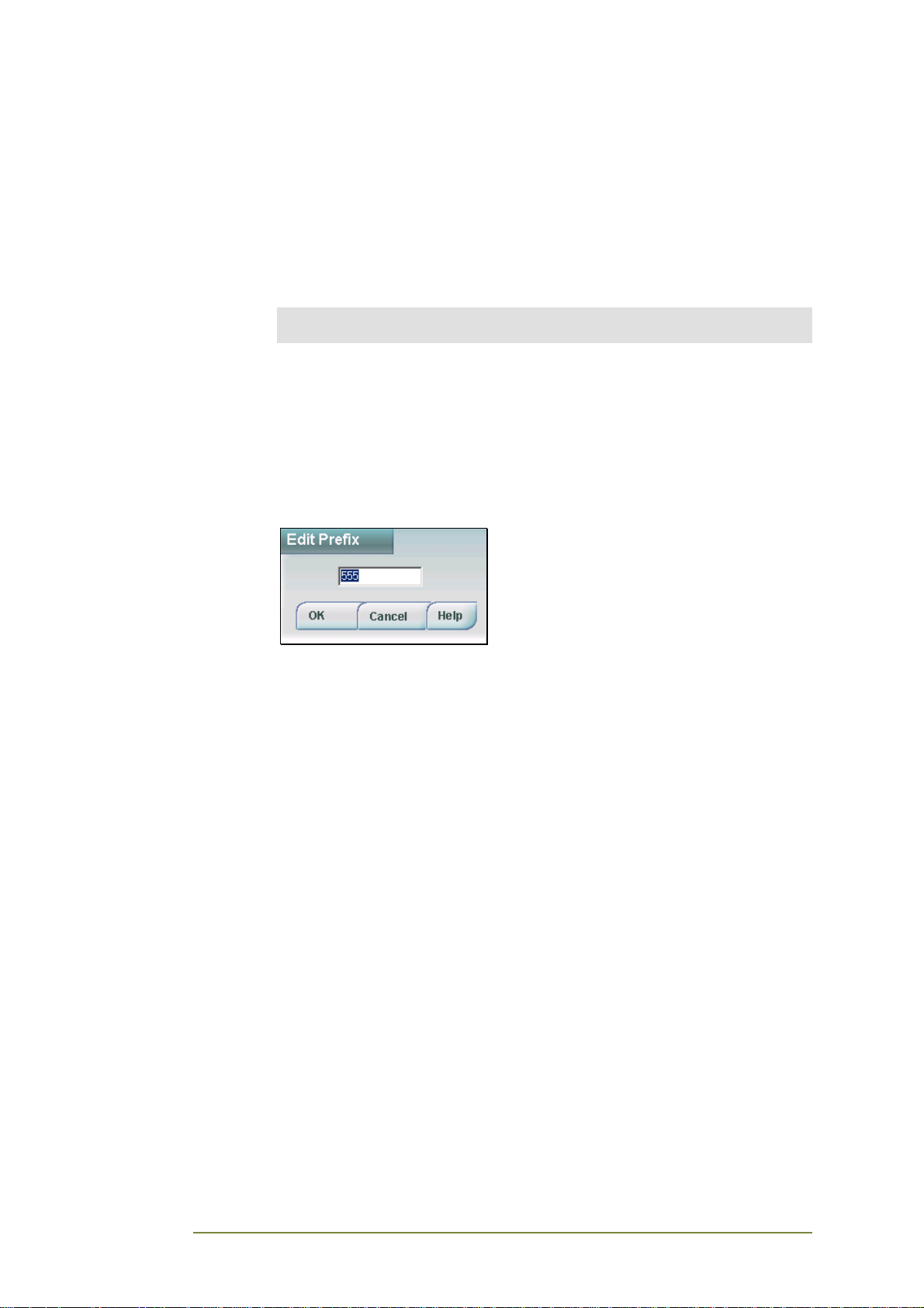
3. Add the Prefix and click OK. The number is added to the channel’s
Allowed Prefix List.
Not to allow a specific prefix on either channel:
1. Check the Not Allowed checkbox to enable the Not Allowed Prefix
List pane. This list displays the cellular operator prefixes your
device cannot call.
2. Click the Add button. The Add Prefix window is displayed.
Note:
Prefixes should not conflict with any existing PBX LCR Rules.
3. Enter dialing prefix, then click OK. The number is added to the Not
Allowed Prefix List.
Editing a calling prefix:
1. Click the prefix you want to edit.
2. Click the Edit button to display Edit Prefix window for the
currently selected number.
3. Change the number and click OK. The updated number appears in
the prefix list.
Deleting a calling prefix:
1. Click the prefix you want to delete.
2. Click the Delete button to delete. You are asked to verify the
delete.
3. Click Yes to approve the delete. The prefix no longer appears on
the prefix list.
CGW-I Cellular Gateway BRI-GSM : Installation and Operation Manual 31
Page 37
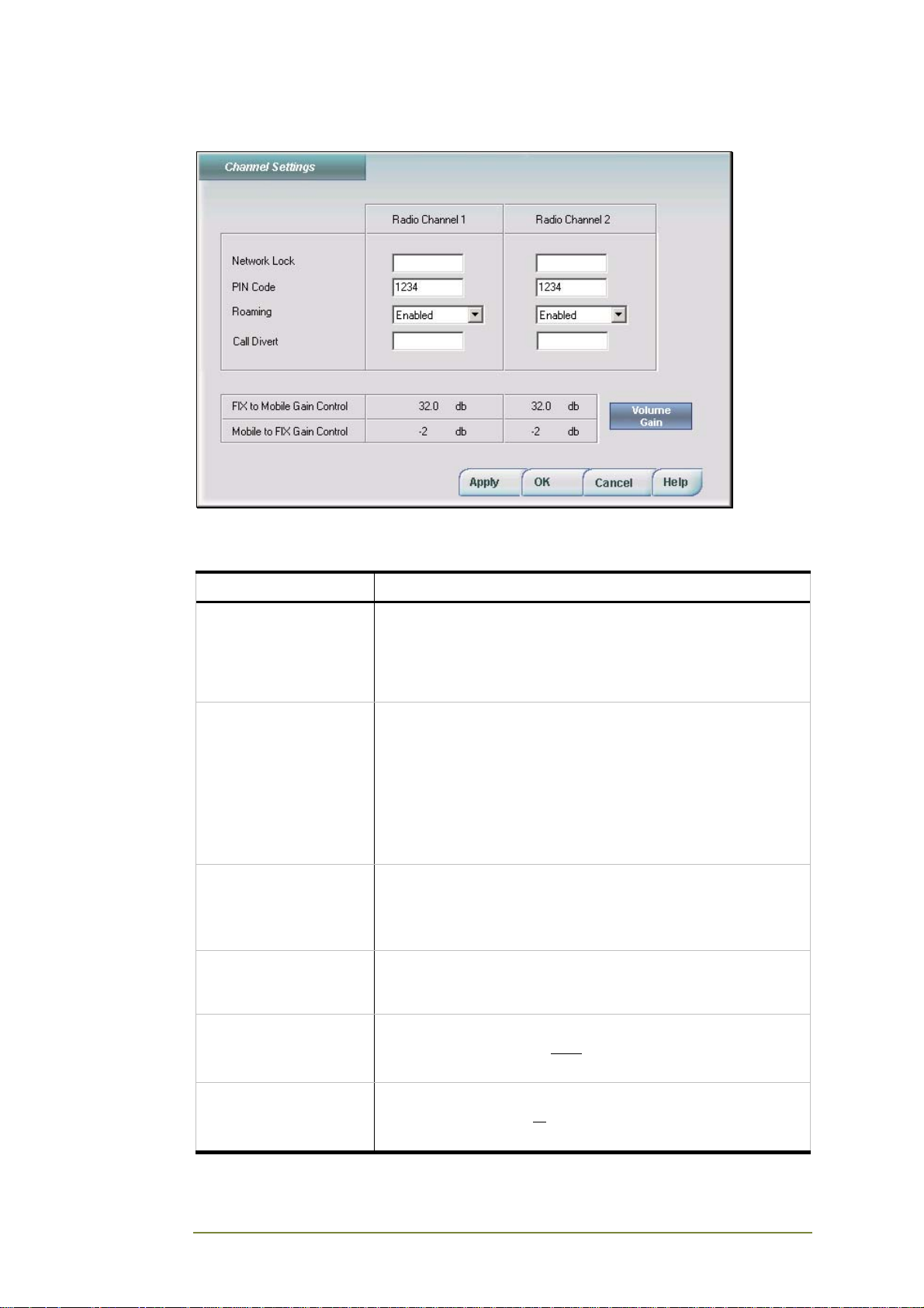
Channel Settings
The Channel Settings window lets you define access to specific cellular
operators and the volume levels for incoming and outgoing calls.
Field Parameter
Network Lock Enter network operator’s number to configure device to work
only with this specific operator. If field left empty, SIM first
tries to register with its home network, but will connect to the
strongest available network if no signal and the Roaming
feature is enabled.
PIN Code Enter password for SIM to protect it from unauthorized use if
removed.
Note: This field remains disabled if network operator details
are the permanent factory setting.
Note: If you enter an incorrect PIN three times in the
Channel Settings screen and are locked out by the SIM, you
must enter the PUK code to unlock the SIM. Call your
network operator to get the PUK code if you do not know it.
Roaming Enable to allow calls to automatically connect to an available
signal which does not necessarily belong to the SIM’s
network operator.
Disable to restrict calls to a specific network operator.
Call Divert To enable the Call Divert feature, enter the number of
alternate cellular gateway channel to which you will reroute
all incoming calls when this channel is busy.
FIX to Mobile Gain
Control
Displays the volume level (decibels) of the sound stream
going into each channel from a fixed telephone extension.
Click the Volume Gain button to adjust the level.
Mobile to FIX Gain
Control
CGW-I Cellular Gateway BRI-GSM : Installation and Operation Manual 32
Displays the volume level (decibels) of the sound stream
leaving each channel to
Click the Volume Gain button to adjust the level.
the fixed telephone extension.
Page 38
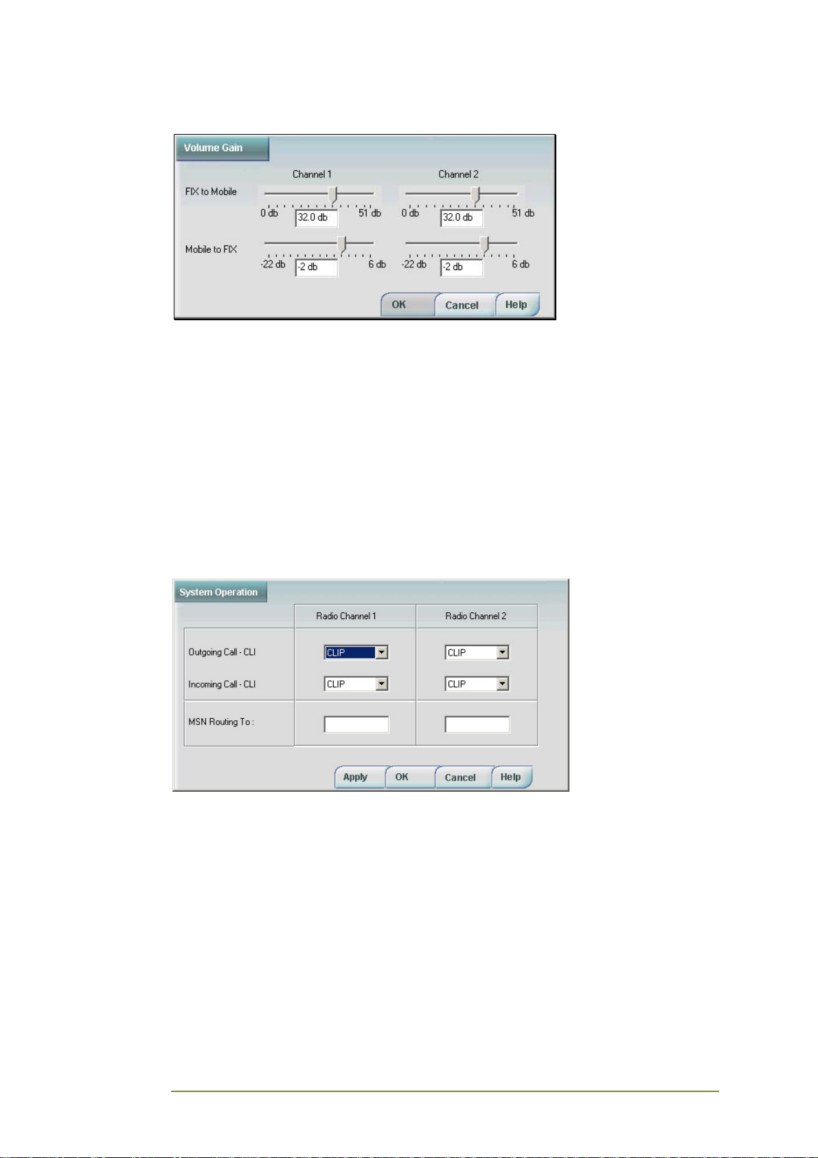
Adjusting the Volume Gain Level
To set the volume level for incoming and outgoing calls:
1. Click the Volume Gain button on the Channel Settings window.
• The FIX to Mobile fields (Channel 1 and Channel 2) display the
volume level of the different outgoing sound streams.
• The Mobile to FIX fields (Channel 1 and Channel 2) display the
volume level of the different incoming sound streams.
2. Click and drag the volume control left (low) and right (high) to set
the volume to most comfortable listening level, then click OK.
Operation System Parameters
The Operation System Parameters window lets you enable the display of
Caller IDs and define call routing options.
CGW-I Cellular Gateway BRI-GSM : Installation and Operation Manual 33
Page 39
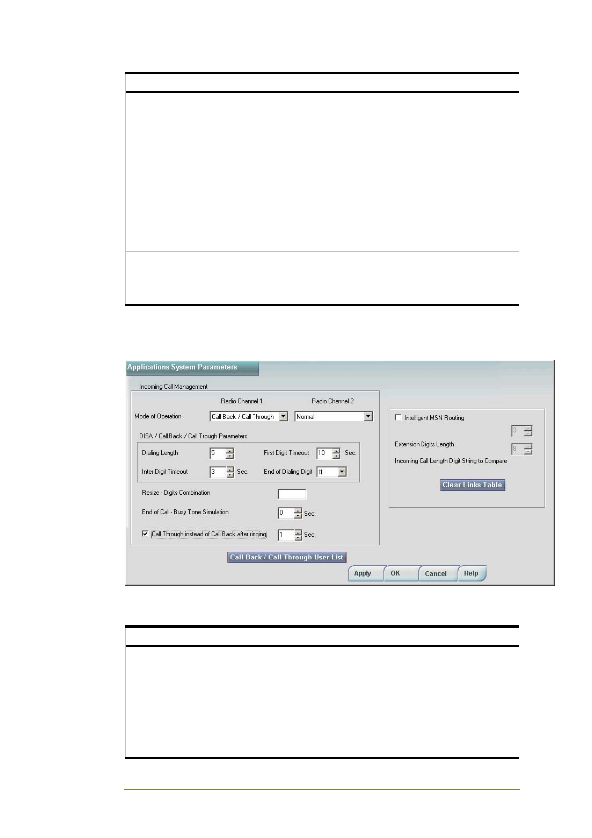
Field Parameter
Outgoing Call – CLI CLIP (Calling Line Identification Presentation)
Transmits the calling SIM card’s number.
CLIR (Calling Line Identification Restriction)
Prevents the transmission of the calling SIM card’s number.
Incoming Call – CLI CLIP (Calling Line Identification Presentation)
Allows transmission of an incoming call’s identification
number.
CLIR (Calling Line Identification Restriction)
Prevents the transmission of an incoming call’s identification
number.
Note: Select CLIR if your PBX is unable to handle varying
incoming caller ID formats.
MSN Routing To Enter the default Multi-Subscriber Number to route incoming
calls made to this specific SIM’s cellular number. The MSN
may be a specific extension, Automated Attendant or Voice
Mail system.
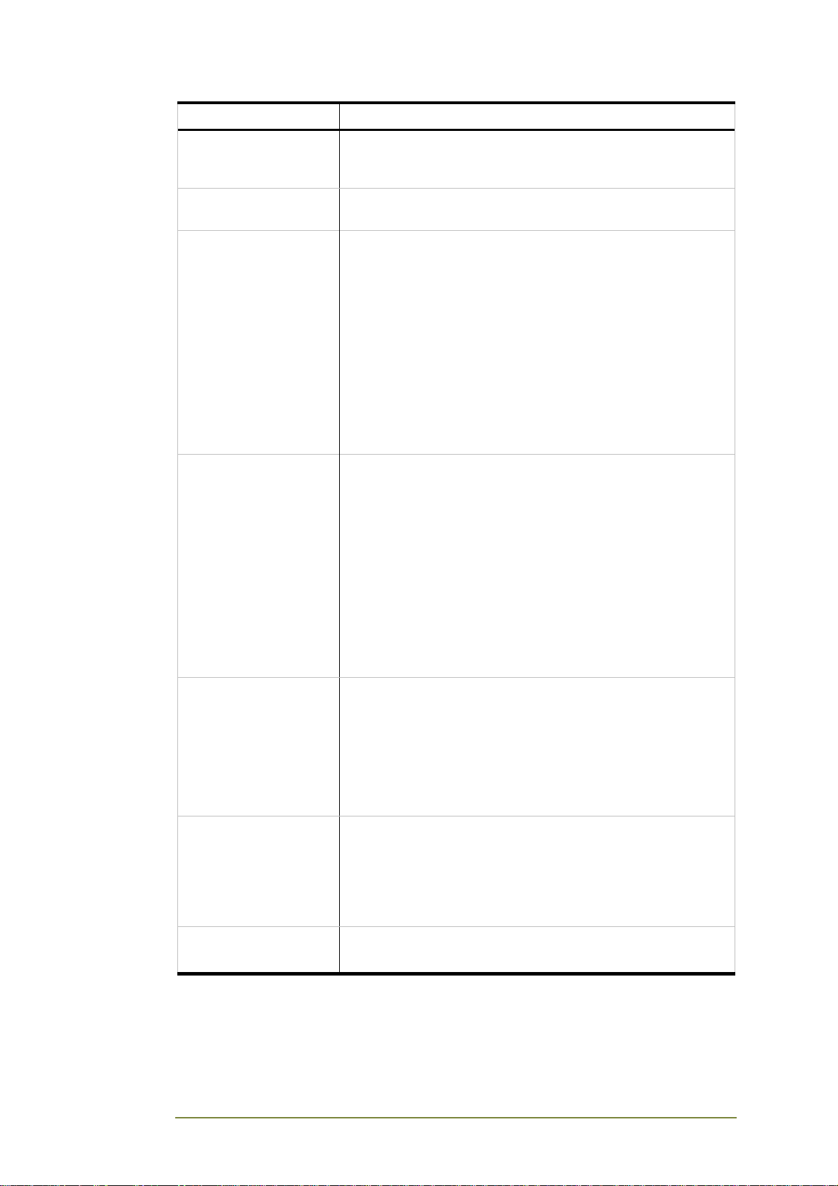
Application System Parameters
To open the System Application window, select System @ Application
System Parameters.
Field Parameter
Mode of Operation Enables to set Normal or TBD mode
Dialing length Sets the dialing length. Defines the maximum number of
digits that can be dialed. Default setting – 5. Maximum
setting – 32.
Inter Digit Timeout Sets the Inter Digits Timeout – maximum time interval in
seconds between DTMF digit inputs. Exceeding this time
interval will execute a call. Default setting – 10. Maximum
setting – 45.
CGW-I Cellular Gateway BRI-GSM : Installation and Operation Manual 34
Page 40
Field Parameter
First Digit Timeout Sets the time interval in seconds for starting DTMF number
dialing. Exceeding this time interval will disconnect a call.
Default setting – 20. Maximum setting – 45.
End of Dialing Digit DTMF character, which specifies the end of dialing. Default –
#. Legal entry – 0-9, *,#.
Resize – Digits
Combination
End of Call – Busy
Tone Simulation
Enables the cellular incoming gateway caller to make a new
call from the gateway to the PBX direction. To have the
option to get dial tone for future dialing, the cellular caller
should be a gateway Call Back/Call Through subscriber.
If the DISA option is enabled for a specific Cellular port, any
incoming cellular caller could get the dial tone and release a
call through the Gateway. To make a new through call from
the gateway to the PBX direction without disconnection from
the cellular network, the caller can enter the New Dial tone
code during conversation using cellular phone’s keypad,
which provides the new Dial tone for through calling. It is
possible to define the New Dial tone code using CGW-I
Manager - configuration PC application.
After the CGW-I gateway picks up an incoming cellular call,
CallBack/Through subscriber receives the dial tone. The
Callback feature subscriber receives the dial tone, and then
the gateway performs call back – returns a call to the
subscriber). When the DISA feature is enabled for a specific
radio channel, any incoming cellular caller can receive the
dial tone and release a call through the Gateway.
If a target dialed PBX extension is busy, gateway provides
the cellular caller a specified time interval to receive a new
dial tone and make new through call. If during this period the
cellular caller did not request the new dial tone and did not
dial “Resize Digits Combination Code”, the gateway will
reject the incoming cellular call.
Call Through instead of
Call back after ringing
Intelligent MSN
Routing checkbox
Extension Digits
Length
Call Back subscriber calls makes incoming call to the CGWI. After the CGW-I gateway picks up an incoming cellular
call, Call Back subscriber has to disconnect during predefined time interval ( 1-60 seconds). Then CGW-I will
implement the Call back action. If a time interval expired, so
Call Back subscriber will get the DISA functionality. Option is
active for the “Call back / Call Through” mode of operation
only !
When selected, enables linking between dialing extensions
and dialed cellular numbers. See Links Table section for
details.
Note: To enable the Intelligent MSN Routing feature, both
the Incoming and Outgoing Call CLI must be set to
Presentation (CLIP).
Defines the length of a dialer’s extension.
Legal range: 0-16 digits.
CGW-I Cellular Gateway BRI-GSM : Installation and Operation Manual 35
Page 41
Field Parameter
Incoming Call Length
Digit String to Compare
Sets the number of digits in an incoming call’s phone
number to compare to linked dialed cellular numbers.
Numbers are counted from right-to-left (last to first).
Legal range: 0-16 digits.
Note: Some DDI cellular numbers automatically include
additional digits, such as a Country Code. By defining the
number of digits on an incoming call, you are able to cut off
additional digits that may cause problems, such as
identifying a called number that is stored in the Links
Database.
Links Table
Your CGW-I device can store up to 1,500 links between outgoing caller IDs
and dialed numbers. When a Direct Dial-In (DDI) calls back, your device
recognizes the DDI’s cellular number in the Links Table and can route the call
to the extension of the person that last dialed this cellular number.
Clearing the Links Table
To clear the Links Table, click the Clear Links Table button. All stored links
created by the Intelligent MSN Routing feature are deleted.
Call Back/Call Through User List
This is the gateway’s database list of subscribers, who are authorized to use
Call Back and Call Through features. It is possible to create up to 250 records
in the subscriber’s database.
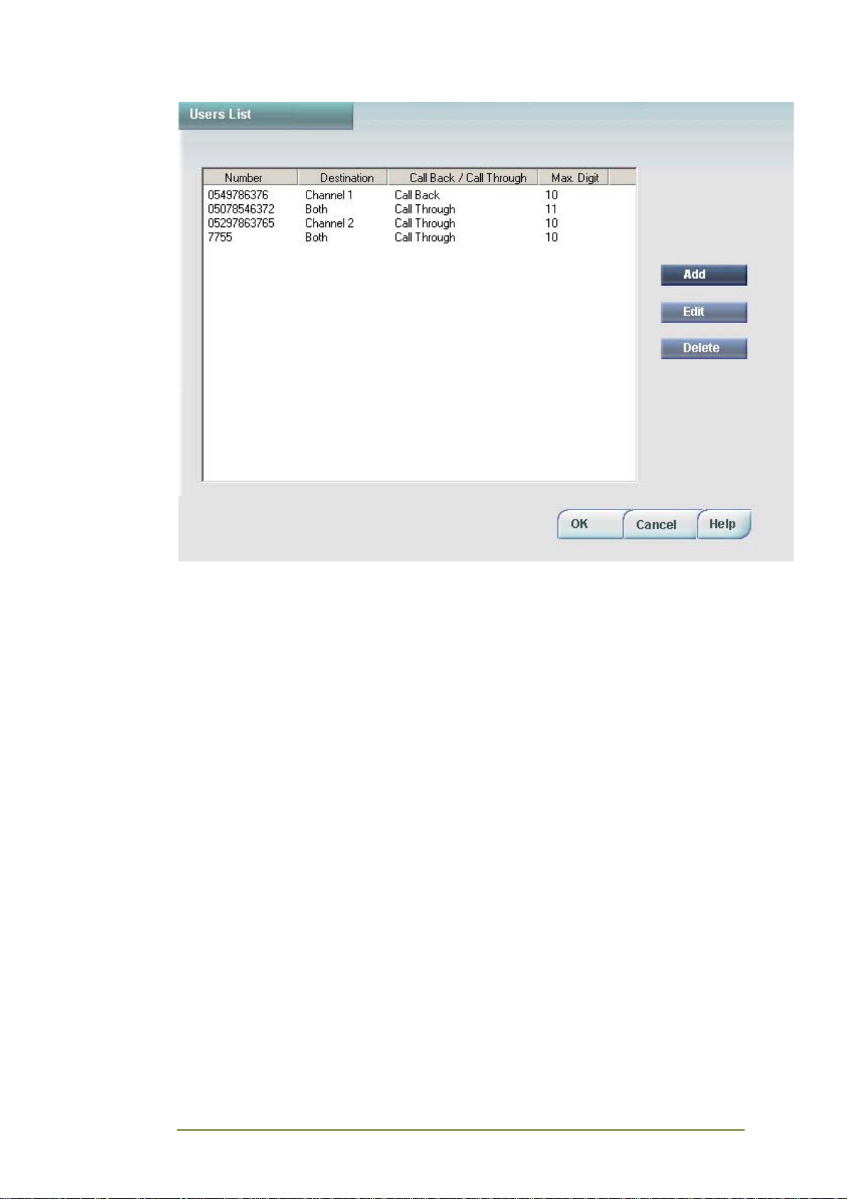
Users List
This screen contains a list of up to 250 subscribers.
CGW-I Cellular Gateway BRI-GSM : Installation and Operation Manual 36
Page 42
CGW-I Cellular Gateway BRI-GSM : Installation and Operation Manual 37
Page 43
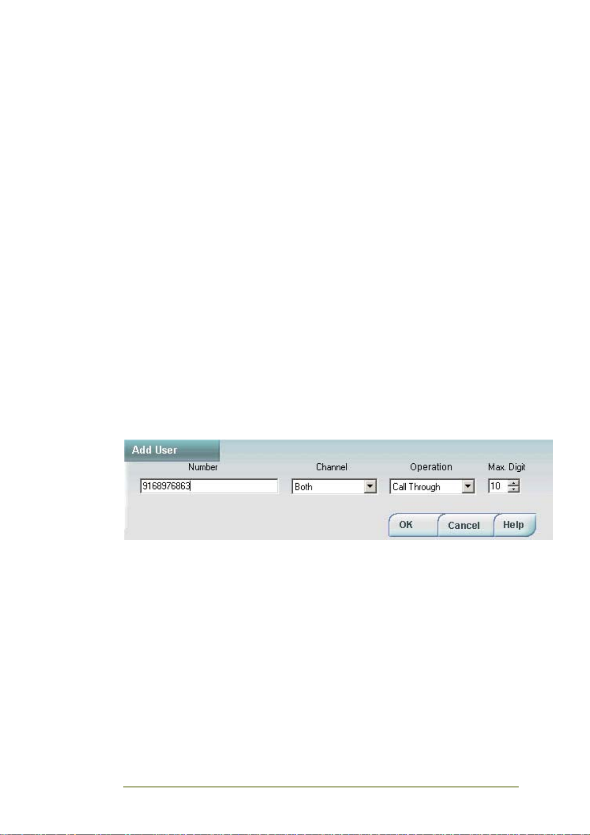
To add a subscriber:
1. Click the Add button. Add User screen opens.
2. Enter the user's details:
• Number – enter the gateway subscriber's phone number (up to
28 digits, 0-9 characters only). When the gateway will recognize
the number, it will perform the operation as defined in
Operation combo-box. The gateway will check the caller number
during an incoming call from the right side and compare it with
the database records. For example: If in the Number field entry is
700, each incoming caller with a number that ends with the
digits 700 (XXXXXX700) will be authorized to use the Call Back
and Call Through features.
• Channel – select the channel from combo-box. This defines a
cellular channel, where the subscriber can call to get Call Back
and Call Through features. It is possible to select Channel 1,
Channel 2 or Both channels.
• Operation – select Call Back or Call Through from combo-box.
This defines a type of operation Call Back or Call Through, which
will be provided to caller if a CLI number matches an entry in the
Numbers list.
• Max. Digit – enter a value in the field or use the arrow buttons
to specify the maximum digits that a gateway’s subscriber may
dial using Call Back and Call Through features.
To edit a subscriber's details:
1. Select a subscriber on the Users List and click the Edit button.
2. Edit the fields as required.
3. Click OK to confirm.
To delete a subscriber:
1. Select a subscriber on the Users List.
2. Click the Delete button. The subscriber is deleted.
CGW-I Cellular Gateway BRI-GSM : Installation and Operation Manual 38
Page 44
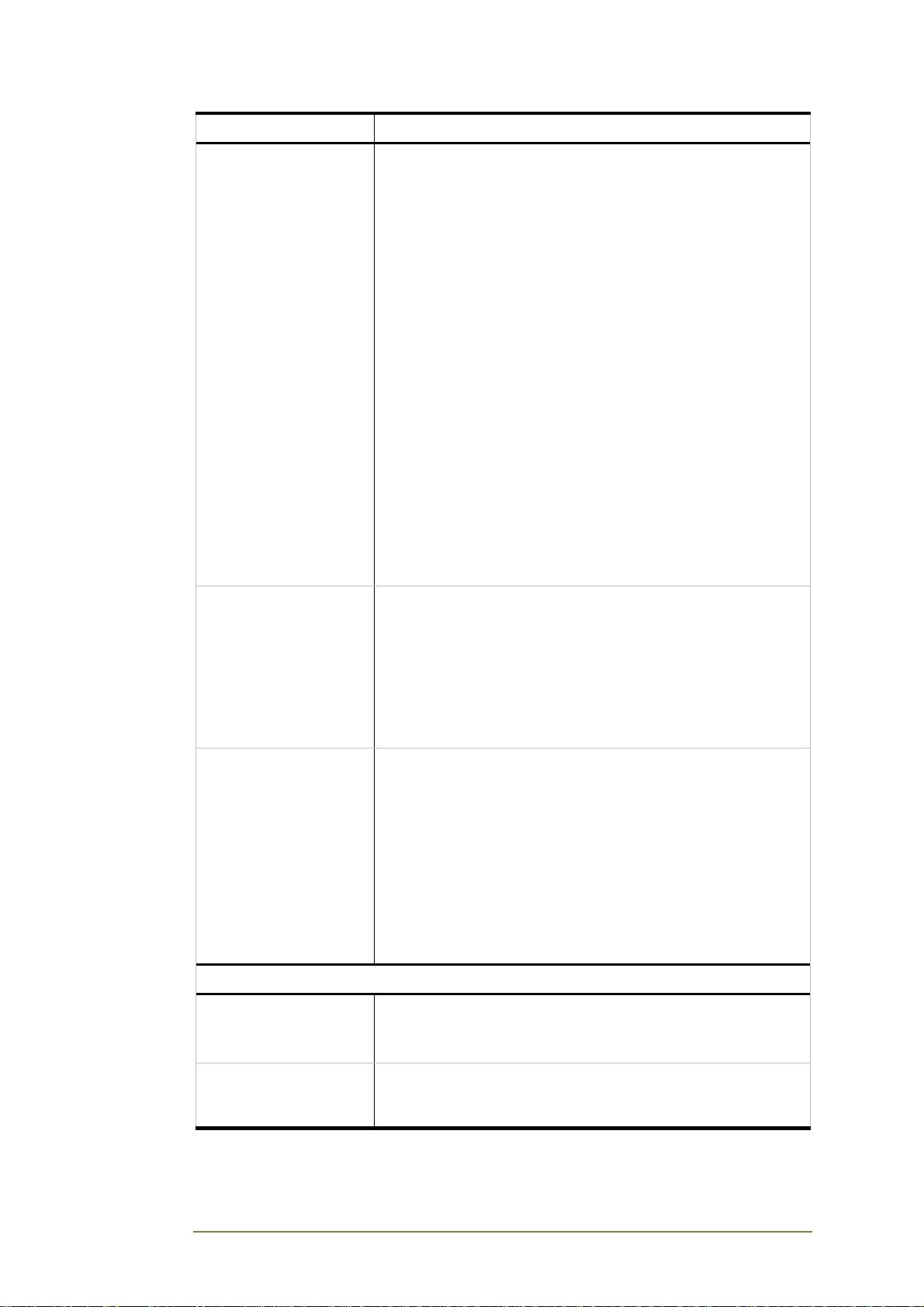
Prepaid Settings
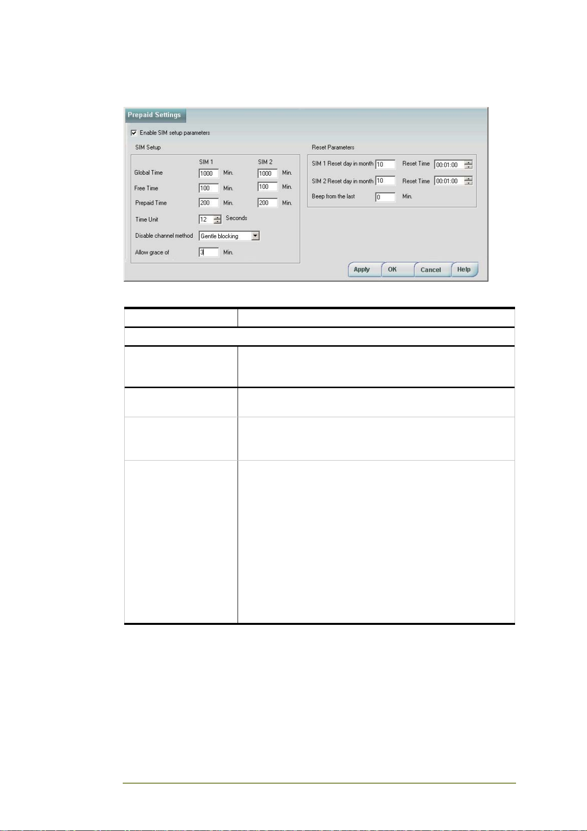
The Prepaid Settings window lets you set up prepaid SIM parameters.
Field Parameter
SIM Setup
Enable SIM Setup
Parameters Checkbox
Global Time Enter the amount of Global time credit awarded by the
Free Time Enter amount of free calling time credit awarded by the
Prepaid Time Enter the number of monthly discounted minutes (calling
Check to enable the SIM Setup and Reset Parameters
below, as well as the Remaining Prepaid SIM Time fields in
the Statistics screen (see page 43).
network provider for each SIM.
network provider for the month for each SIM.
Range: 1-9999
time threshold) for each SIM card, not including Free Time
minutes. The remaining amount of unused prepaid time is
displayed on the Statistics screen (page 43).
Range: 1-9999
Before this threshold level is reached, an alarm will be
triggered if the SIM Operation Time alarm is set (checked).
For example, you may purchase a 5000 minute SIM card
that allows 1,000 minutes at a discounted cost per minute
each month. Any calls made beyond the 1,000 minutes will
cost more. In such a case, you must set the Prepaid Time to
1,000 to alert you must stop using the card and replace it
with a new discounted card.
CGW-I Cellular Gateway BRI-GSM : Installation and Operation Manual 39
Page 45
Field Parameter
Disable Channel
Method
Choose one of the following when a SIM card exceeds the
maximum number of minutes allowed (i.e., free + minutes +
grace/part of grace):
No Blocking: Unit will never block outgoing calls
Precise Blocking: Unit will disable outgoing calls exactly
when the Prepaid Time is finished, even while a
conversation is in progress.
Gentle Blocking: Once Prepaid Time is finished, unit will
allow the call to continue for allowed Grace Time period, but
will disable further outgoing calls.
This function works independently for each channel, so if 1
SIM card has reached its limit, you can still make calls using
the SIM.
Note: Once a radio channel is disabled, the LCD will display
the message “Blocked Outgoing”.
If a channel is blocked because Prepaid Time is finished,
you can do one of the following:
• Increase Prepaid Time for the SIM, then perform “Send
Parameters” action. This will release blocking of outgoing
calls.
• Change the Reset Day and Time to the current day and
time.
Allow grace of When Gentle Blocking is selected in Disable Channel
Method, the number of minutes that a call which has
exceeded the SIM’s Prepaid Time credit (and is now using
more expensive calling credit) may continue without being
disconnected.
Range: 0-99
If 0 is entered, a call that exceeds the Prepaid Time value
will be disconnected immediately.
Time Unit Amount of real connection time in seconds that equals what
the network operator defines as one unit of Charge
Connection Time.
For example, a 12 second Time Unit may equal 1 unit of
Charge Time. If a call is 15 seconds long, the network
operator will charge for 2 units of connection time (i.e., 24
seconds of Accumulated Time), regardless of the true length
of the call.
Note: Before you can change the Time Unit, you must reset
the Accumulated Time counter to 0. For more details, see
the Resetting Checked Counters section below.
Reset Parameters
SIM Reset Day The day in the month that your SIM time counters (i.e.,
Prepaid, Free, and Remaining Prepaid) are reset.
Range: 1-28
Reset Time The time that your SIM time counters (i.e., Prepaid, Free,
and Remaining Prepaid) are reset on the day you have set
for the associated SIM card.
CGW-I Cellular Gateway BRI-GSM : Installation and Operation Manual 40
Page 46
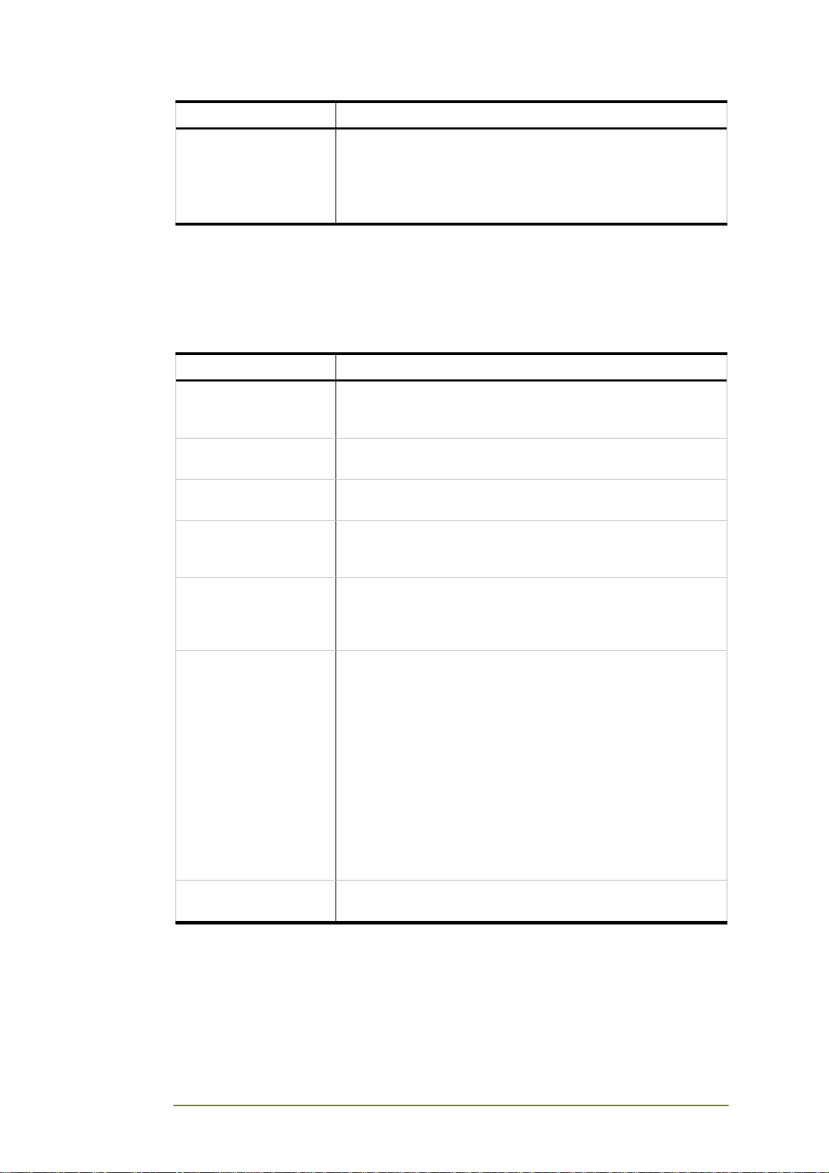
Field Parameter
Beep in the last The number of minutes before your Prepaid Time credit is
finished that the system will begin beeping (once each
minute) to alert you that a SIM’s discounted time is almost
finished.
Range: 0-99
Controlling the CGW-I
The System menu includes a number of options for resetting, clearing and
closing your CGW-I device. To choose one of these options, select: System @
Control. The options are described below:
Function Description
Reset Device Performs a reset on your device if it stops responding. When
your device is reset, all temporary data is lost (i.e., counters
and MSN Routing Links).
Reset GSM Channel Resets the engine of the selected channel (1 or 2) if channel
stops responding.
Reset ISDN Interface Resets communications protocol between device and ISDN
layers 1, 2, and 3.
Cellular Daily Restart Allows you to set a time for a daily cellular engine restart to
be performed automatically by the unit for each of the two
channels.
Gentle Closing Prevents any new connections to be made on any channel.
Any current connection will remain open until the call is
ended. After doing a gentle close, you must select Reset
Device to use it again.
Echo Parameters Echo parameters influences on the audio quality. This
parameter changes the system hardware’s interactivity with
the firmware. Echo Parameter argument can be 0 , 1 and 2,
where
[0] Supports with the Cellular Module Q24CL001/002 &
Q2686
[1] Supports with the Cellular Module Q24CL002 &
Q2686
[2] Support with the Cellular Module Q2686 Only
Note: ‘Echo Parameters’ can be changed by the qualified
technical person only. Changing ‘Echo Parameters’ takes
effect on the Cellular Gateway functionality.
Back to Factory
Defaults
Resets all parameters to their default settings.
CGW-I Cellular Gateway BRI-GSM : Installation and Operation Manual 41
Page 47
3.5. Report Menu
The Reports menu lists the following options to monitor how your CGW-I is
handling call traffic:
• Properties
• Statistics
• CDR (Read and Clear)
• Alarms
• Status
Each option is described in one of the following sections.
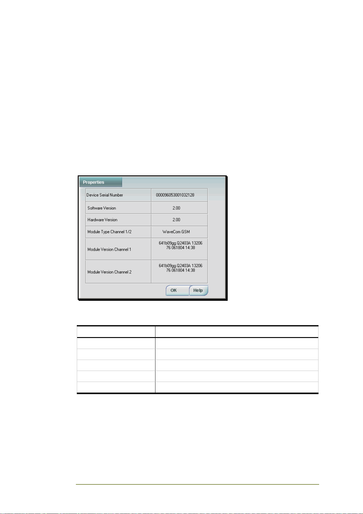
Properties
The Properties window displays the specific manufacturing details of your
CGW-I device. They are as follows:
Property Manufacturing Detail
Device Serial Number Serial number of your device.
Software Version Software version of your device.
Hardware Version Hardware version of your device.
Module Type Module type used for both channels.
Module SW Version Module software version used by each channel.
CGW-I Cellular Gateway BRI-GSM : Installation and Operation Manual 42
Page 48
Statistics
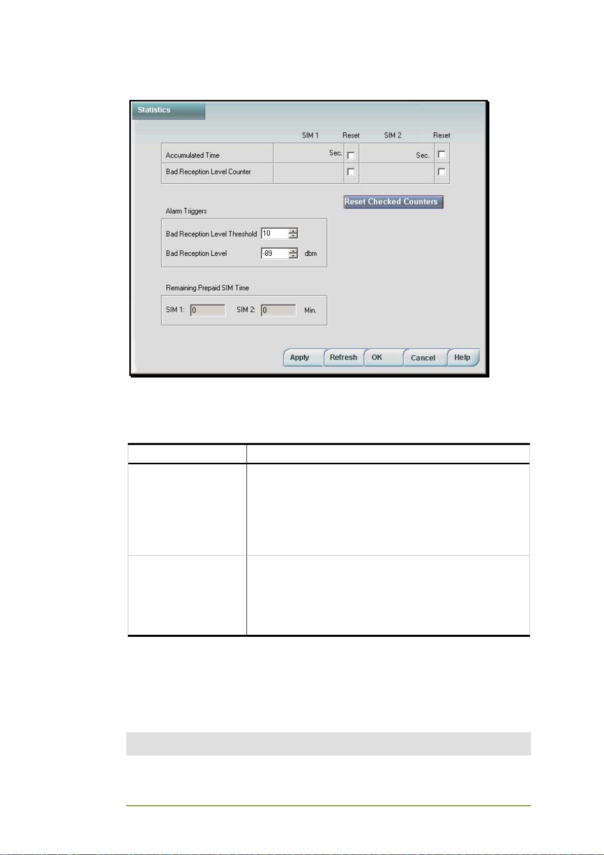
The Statistics window displays the amount of time each SIM is used and if
there are problems with reception.
The counters are explained in the following table.
Field Parameter
Accumulated Time Total amount of time in seconds, based on the defined Time
Unit, that each SIM was used for outgoing calls since the
counter was last reset.
For example, if the real total time of a call is 30 seconds, but
the Time Unit was set to a 12 second Time Unit interval, the
Accumulated Time will be logged as 36 seconds (i.e., based
on the use of 3 Time Units).
Bad Reception Level
Counter
Number of times that each SIM experiences a Bad
Reception Level for more than FOUR consecutive minutes.
The number displayed is from the time the counter was last
reset.
For example, if the SIM experiences a Bad Reception Level
for 9 consecutive minutes, the counter is increased 2 times.
Resetting Checked Counters
To reset a counter, check it and click the Reset Checked Counters button.
The counter is reset to 0. You can check and reset multiple counters at the
same time, but CGW-I Manager will only reset the counters that are
checked.
Note:
When you reset checked counters, CGW-I Manager makes a connection to the device.
CGW-I Cellular Gateway BRI-GSM : Installation and Operation Manual 43
Page 49
Reception Level Alarm Triggers are explained in the following table.
Field Parameter
Bad Reception Level
Threshold
Bad Reception Level Define the dbm level that you consider to be bad reception.
Note:
Thresholds are designed to alert you to potential problems. For details on setting up
alerts, see System Alarms section.
Number of times that the Bad Reception Level counter is
incremented before triggering an alarm.
For example, if the threshold is set to 10, an alarm will be
triggered the tenth time that the Bad Reception Level
Counter reaches the defined Bad Reception Level for at
least four (consecutive) minutes.
When this level is reached for more than FOUR consecutive
minutes, your device will increment the Bad Reception Level
Counter by one.
Remaining Prepaid SIM Time fields are explained in the following table.
SIM 1, SIM 2 When the Prepaid SIM Time field is enabled (see System
Operation screen, page 34), this field displays the total
number of Prepaid Time still available after subtracting the
total number of minutes already used from the SIM. Free
Time minutes are not included in the Prepaid SIM Time
calculation.
If the SIM Setup Parameters are not enabled, there is no
Prepaid SIM Time and the Remaining Prepaid SIM Time
field remains empty.
To update the Remaining Prepaid SIM Time display, click
the Refresh button to read current parameters and
calculated remaining time from the last call that was
complete.
Note: The time calculated in minutes is based on the Time
Unit value defined in the System Operation screen.
Reading the CDR (Call Detail Record)
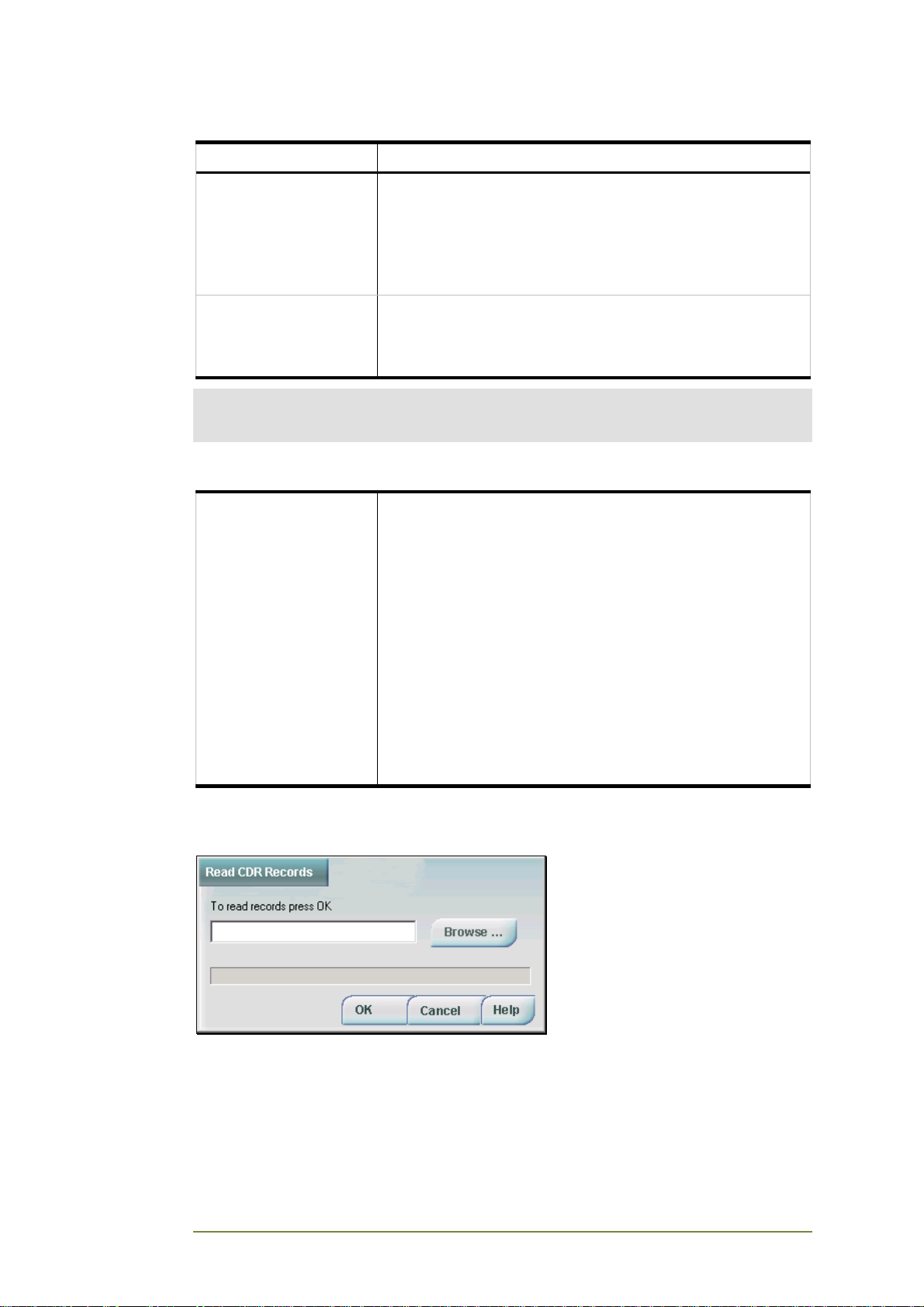
The Read CDR Records window lets you view the current Call Detail Record
of both channels or open a previously saved record.
CGW-I Cellular Gateway BRI-GSM : Installation and Operation Manual 44
Page 50

Each Call Detail Record can hold up to 2,500 rows. Each row displays:
• Unique Tracking Number
• If the call was Incoming (In) or Outgoing (Out)
• Start Time of the call
• Start Date of the call
• End Time of the call
• End Date of the call
• Called Number
• Calling Number
• Radio Channel
• ISDN Channel
To read the current CDR:
1. Select Report @ CDR @ Read CDR. The Read CDR Records
window opens.
2. Enter the name for the new CDR you want to create and click OK.
The file is saved in the default CGW-I directory.
To open an existing CDR or to change the path of the new CDR:
1. Click the Browse button to display the Open file window.
2. Enter the name of the new or existing CDR file, then select the
directory if it is not the default CGW-I directory.
3. Click Open. The path and filename now appear in the Read CDR
field.
4. Click OK to view the file.
CGW-I Cellular Gateway BRI-GSM : Installation and Operation Manual 45
Page 51
To clear the current CDR:
Select Report @ CDR @ Clear CDR. The CDR Records are deleted from the
CGW-I device’s memory
System Alarms
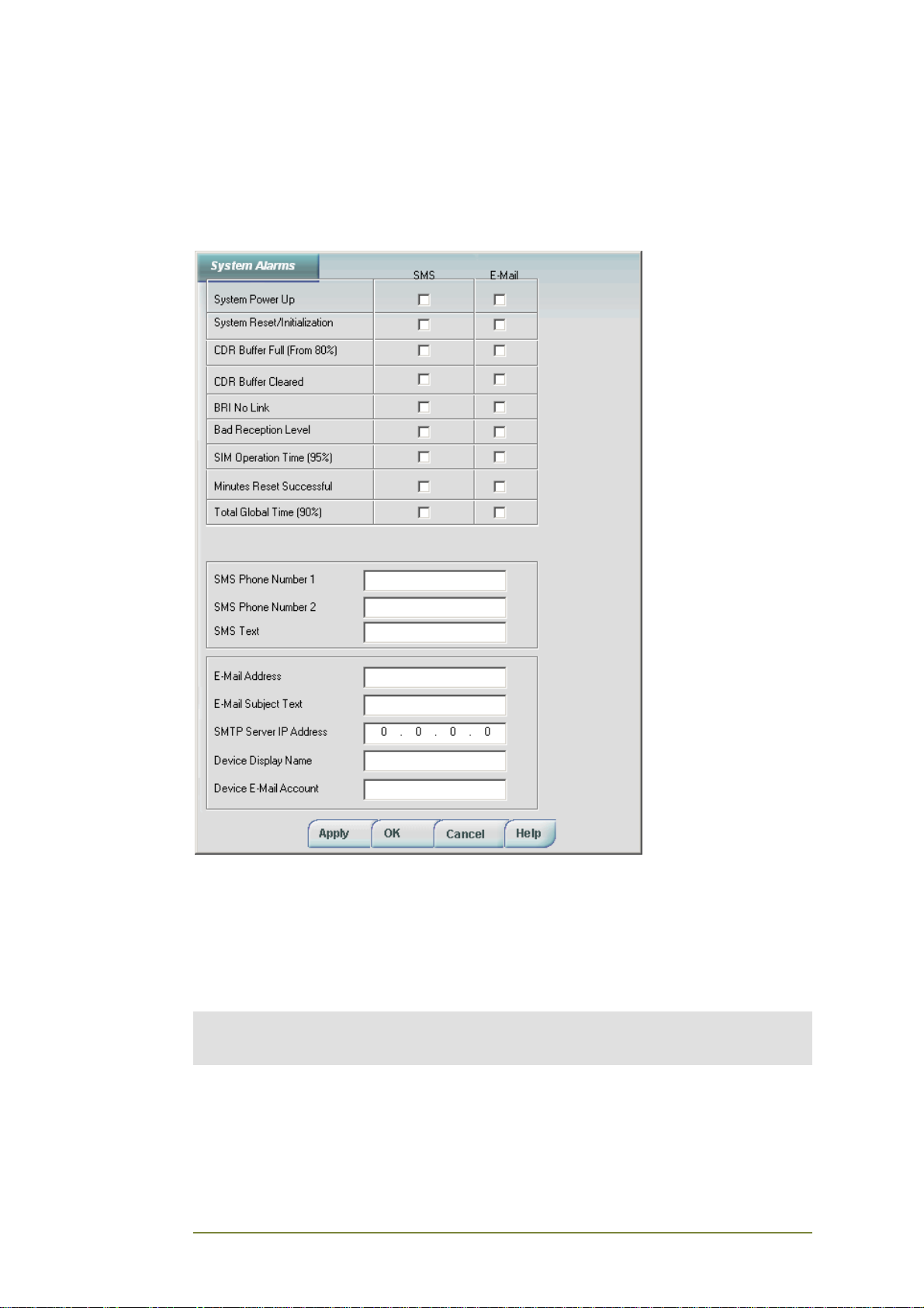
The System Alarms window lets you define what alarms the CGW-I device
should trigger and where to send notification. Alarm notifications apply to
the device and both SIM cards, where applicable.
The following is a list of the different triggers that can prompt your CGW-I
device to send an alarm. You must check the method of notification (i.e.,
SMS, E-mail) you want for each alarm.
Note:
Your CGW-I can only send an E-mail system alarm if it is connected to a LAN with an IP
connection.
CGW-I Cellular Gateway BRI-GSM : Installation and Operation Manual 46
Page 52
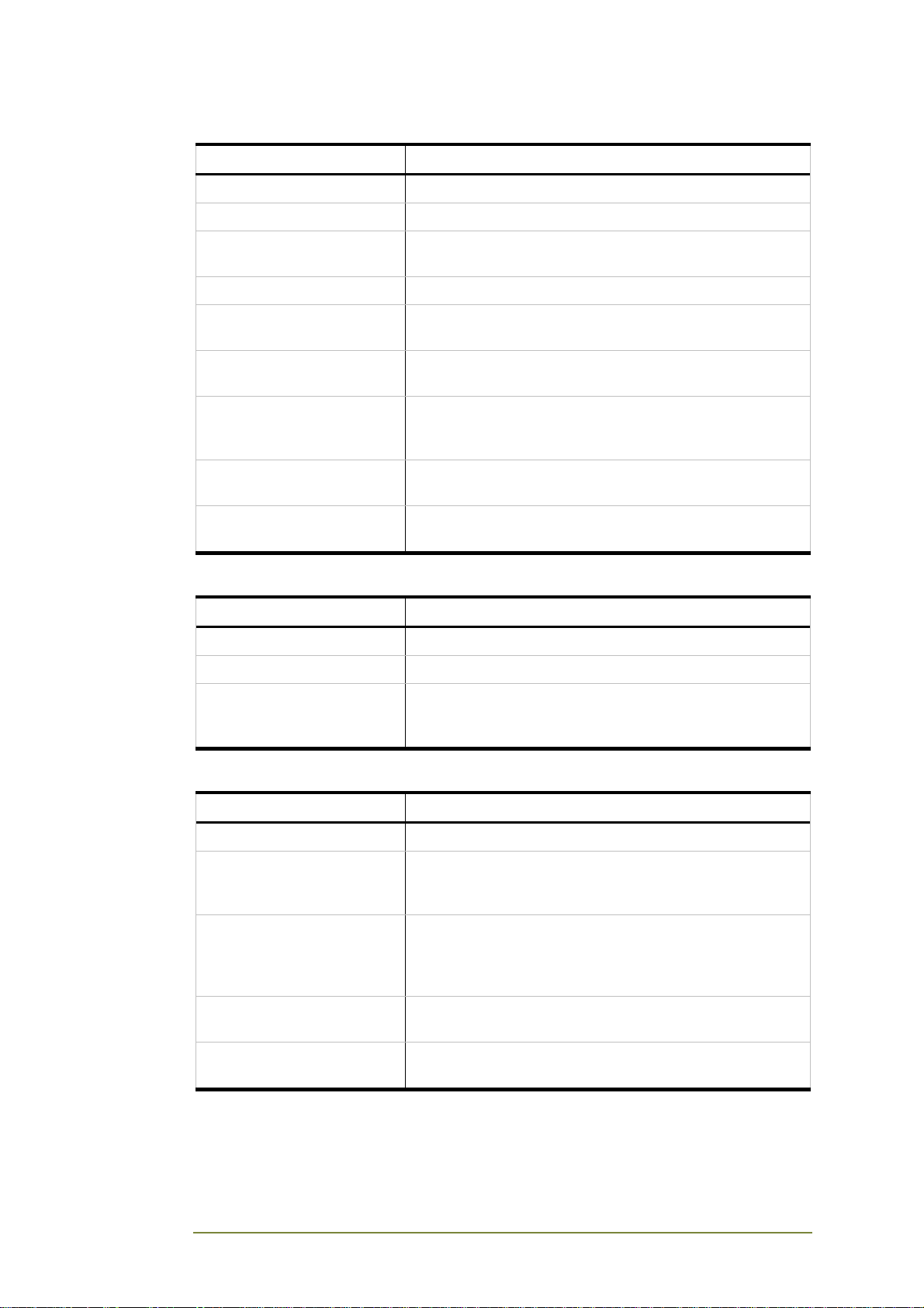
Field Parameter
System Power Up Send notification when device is powered up.
System Reset/Initialization Send notification for each system reset or initialization
CDR Buffer 80% Full Send notification when CDR Buffer reaches 80%
threshold.
CDR Buffer Cleared Send notification when CDR is cleared.
No BRI Link Send notification when the BRI link to your device is
broken.
Bad Reception Level Send notification when the Bad Reception Level counter
reaches the threshold level set in the Statistics window.
SIM Operation Time (95%) Send notification when a SIM card reaches 95% of the
Remaining Prepaid SIM Time value, defined in the
System Operation window.
Minutes Reset Successful Send notification when monthly SIM time counters are
successfully reset.
Total Global Time (90%) Send notification when Global SIM time counters are
more than 90% full.
The following table lists the information required to send an SMS alert.
Field Parameter
SMS Phone Number 1 Enter the first number to send an SMS notification.
SMS Phone Number 2 Enter the second number to send an SMS notification.
SMS Text Enter the subject heading text for all SMS notification.
For example, you may want to know the location of your
CGW-I device triggering the alarm.
The following table lists the information required to send an E-mail alert.
Field Parameter
E-mail Address Enter the E-mail address to send a message.
E-mail Subject Text Enter the subject text for each E-mail notification. For
example, enter the name and location of your device
triggering the alarm.
SMTP Server IP Address Enter the SMTP Server’s IP Address. You can press the
space bar to move to the next part of the address. If you
enter a number greater than 255, CGW-I automatically
resets the number to 255.
Device Display Name Enter the name of your device that is displayed on
E-mail
Device E-mail Account Enter the account used to send all notifications for your
device.
CGW-I Cellular Gateway BRI-GSM : Installation and Operation Manual 47
Page 53
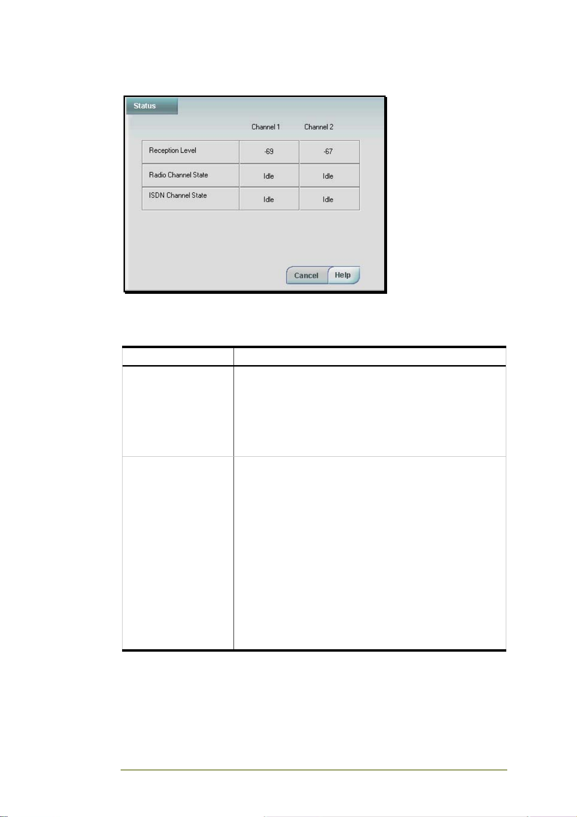
System Statuses
The Status window provides a dynamic display of the following status levels
for each radio channel. For more details on Error messages, which are also
displayed on the LCD, see page 15.
Status Description
Reception Level The level of the received signal.
Range: -113 dBm (weak) to -51dbm (hi).
If reception level is low, the antenna location or type of cable
may need to be improved.
Suggestions to improve antenna placement: move close to
window or to a higher floor, place on larger metal plate,
connect cable providing lower signal loss.
Radio Channel Status
States
Displays status of each radio channel:
• Idle
• Calling Out
• Connected
• Disconnecting
• Ringing In (Receiving incoming call)
• Initialize (After Reset or Power Up)
• Stopped (Due to communication error)
• HW Reset
• No Radio Engine
• Disable
• Sending SMS
• No SIM Time.
CGW-I Cellular Gateway BRI-GSM : Installation and Operation Manual 48
Page 54
Status Description
Radio Channel Status
States
ISDN Channel Status
States
Displays status of each radio channel:
• Idle
• Calling Out
• Connected
• Disconnecting
• Ringing In (Receiving incoming call)
• Initialize (After Reset or Power Up)
• Stopped (Due to communication error)
• HW Reset
• No Radio Engine
• Disable
• Sending SMS
• No SIM Time.
Displays one of the following ISDN channel states:
• Idle
• Calling Out (Making an outgoing call)
• Connected
• Disconnecting
• Ringing In (Receiving an incoming call)
• Initializing (After Reset or Power Up)
• ISDN Interface Error Layer (ISDN Protocol Layer error)
• No Sync (Synchronization error)
• No Link (PBX physical link error)
CGW-I Cellular Gateway BRI-GSM : Installation and Operation Manual 49
Page 55
4. Appendix A:
Technical Specifications
Model Device
GSM Network Type GSM Phase II
GSM Module (2) Integrated Dual Band (900/1800 or 850/1900 MHz)
SIM card Plug-in, 3V or 5V, small
Transmission Power Max. 2W / 850 MHz
Max. 2W / 900 MHz
Max. 1W / 1800 MHz
Max. 1W / 1900 MHz
Receiver Sensitivity -104 dBm
ISDN Interface Point
Reference
ISDN Interface PtP or PtMP for FIX TEI and AUTO TEI
ISDN Type EuroISDN (Standard, In Bound DTMF Dialing, France,
Dial Length Up to 5 digits – operator services or emergency calls
Antenna Frequency 800-1900 MHz
Antenna Maximum
Power
Antenna Gain 2.5dB
Antenna Cable Length 2 meters
Antenna Polarization Omni
Antenna VSWR <1.5
Antenna Impedance 50Ω
Connectors RS-232 Connector – RJ-11
TE or NT
Germany), 1TR6 (Germany)
Up to 16 digits – normal GSM operation
2W
Power Supply Connector – DC Power Jack
Antenna Connector – SMA Female (2)
LAN Interface Connector – RJ-45
ISDN – RJ-45 (2)
Internal Backup Battery Lithium battery
Power Supply Input:
Power Supply Output:
Temperature Range 0°C-45ºC /32ºF-113ºF
Max. Relative Humidity 95%
Dimensions (HxWxD)
(without connectors)
CGW-I Cellular Gateway BRI-GSM : Installation and Operation Manual 50
110VAC, 60Hz
230VAC, 50Hz
9VDC, 1.5A
215x42x125mm
Page 56

CGW-I Cellular Gateway BRI-GSM : Installation and Operation Manual 51
 Loading...