

Operating manual VK 30.03
Material selections switch
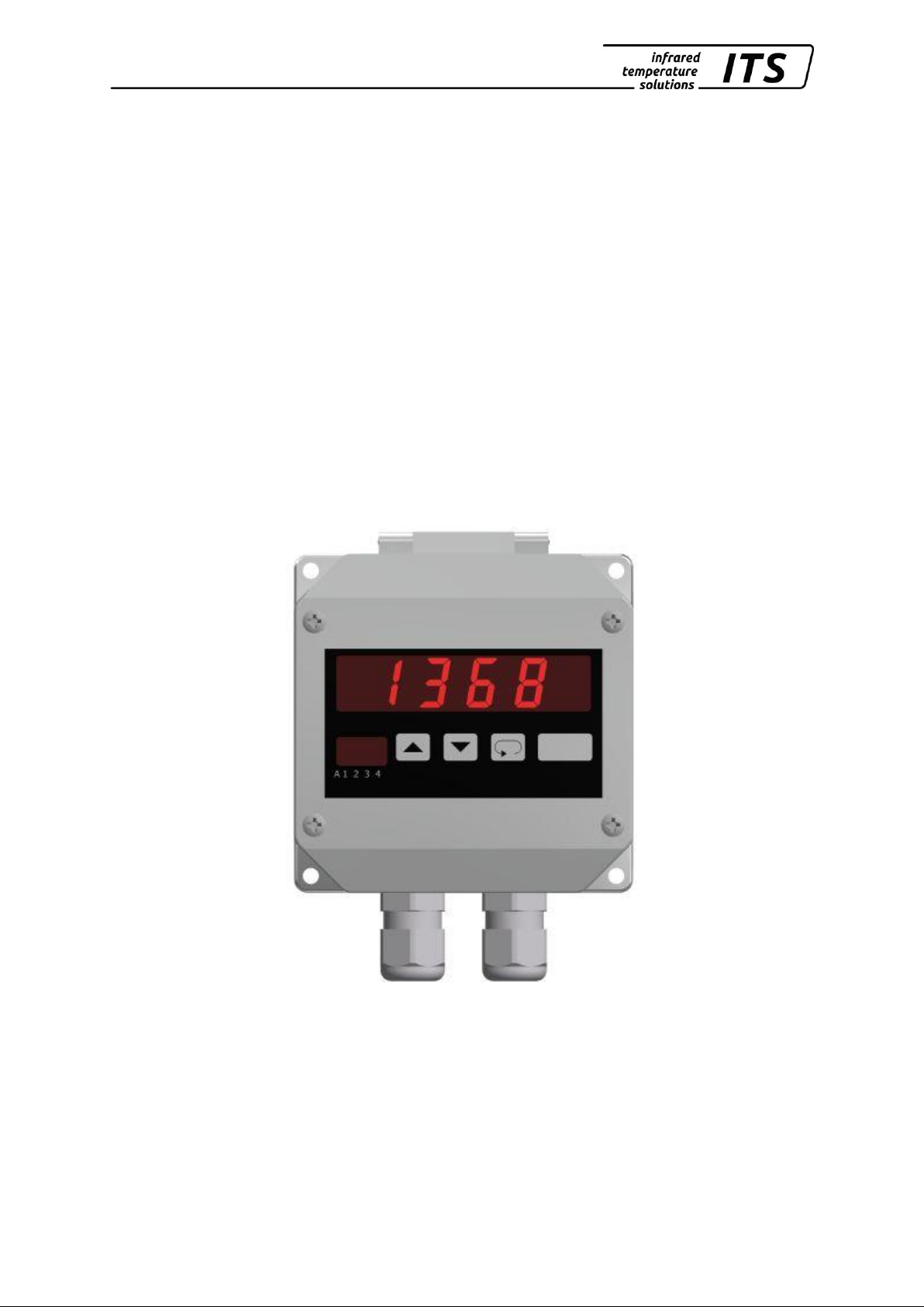
VK 30.03
Ident.-No.: 109 8756 12/2018

Operating manual VK 30.03
Contents
1 Miscellaneous ............................................................................. 1
1.1 Information about this manual ........................................... 1
1.2 Explanation of the symbols ................................................ 1
1.3 Liability and Warranty ........................................................ 1
1.4 Copyright ........................................................................... 2
2 Safety .......................................................................................... 2
2.1 Intendend use .................................................................... 2
2.2 User’s responsibility ........................................................... 3
2.3 Safety requirements .......................................................... 3
2.4 Radio interference suppression / EMV .............................. 3
2.5 Quality Management Certification ...................................... 3
2.6 Environmental Management .............................................. 3
3 General ........................................................................................ 4
4 Connection ................................................................................. 4
4.1 Connection plan ................................................................ 4
4.2 Current output 4 – 20 mA .................................................. 4
4.3 Parameterization VK 30.03 ................................................ 6
5 Parameterization pyrometer PA ................................................ 7
5.1 Configuration I/O (configuration layer: C010) ............... 7
5.2 Display of internal measured values .................................. 7
6 Shipping, Packaging and Disposal ........................................... 8
6.1 Inspecting your shipment ................................................... 8
6.2 Packaging .......................................................................... 8
6.3 Disposal of used apparatus ................................ ............... 8
810-het
VK30.03_en.doc
18.12.2018

Operating manual VK 30.03
1
1 Miscellaneous
1.1 Information about this manual
The Operating Manual shall enable the user to install the material selection switch and those accessories, which are necessary.
Before starting installation, be sure to read and understand this entire
manual, in particular the chapter on safety! The instructions contained in
this manual, especially those concerning safety, as well as site-specific
regulations for accident prevention must be complied with at all times!
1.2 Explanation of the symbols
Important safety-related references in this manual are marked with a
symbol. It is imperative that you observe the safety precautions or instructions indicated by these symbols. Failure to do so might result in
accidents involving physical injury and/or material damage
CAUTION!
This symbol indicates important information which, if neglected, might
result in material selection switch damage, malfunction or breakdown.
PLEASE NOTE!
This symbol points out guidelines which should be heeded for efficient
and trouble-free operation.
1.3 Liability and Warranty
All information compiled in this manual is in accordance with applicable
regulations. The statements made are based on state-of-the-art technology and reflect our extensive knowledge and many years of experience.
PEASE NOTE!
Always carefully read this Operating Manual before beginning any
work on or with the instrument, especially prior to installation and
initial setup! The Manufacturer shall not be held liable for any
damages or malfunctions arising from a disregard of the warnings
and instructions contained herein.
This Operating Manual must be retained for future use. Please ensure
that all persons who wish to operate the instrument have access to this
manual.

Operating manual VK 30.03
2
1.4 Copyright
This Operating Manual should be treated as confidential. It is solely intended for use by persons involved with the instrument. This manual
may not be made available to a third party without prior Manufacturer’s
consent. Please contact the Manufacturer if the need should arise.
PLEASE NOTE!
The data, texts, charts, drawings, images or other representations contained in this manual are copyright-protected and furthermore, subject to
intellectual property rights. Violators will be prosecuted. Unauthorised
use and copyright infringement will be subject to penalty by law.
Reproductions of any kind, in whole or in part, as well as the exploitation
or disclosure of this manual’s content without the explicit written approval
of the Manufacturer are expressly prohibited by law. Violations shall be
subject to compensation claims by the Manufacturer. The right to claim
additional indemnities remains reserved.
2 Safety
This chapter outlines all important safety aspects to be considered for
optimum employee protection and to ensure safe and reliable operations.
2.1 Intendend use
The pyrometer is solely intended for non-contact measurement of temperatures as described in this manual. Any other use is not intended.
Operational safety can only be ensured when the instrument is used for
its intended purpose
CAUTION!
It is prohibited to use the pyrometer for any other purpose beyond what
is specified in this manual. Using the instrument in any other manner will
be considered as improper.
The Manufacturer/Authorised Agent shall not be held liable for any damages or loss resulting from such unintended or improper use; in this case
the risk is solely borne by the user.

Operating manual VK 30.03
3
2.2 User’s responsibility
The material selection switch may only be used when it is in perfect
working condition.
2.3 Safety requirements
The instrument works with an operating voltage of 24 VDC. The voltage required for operation must be supplied by a separate power supply. This
power supply unit must conform to directive IEC 61010.
2.4 Radio interference suppression / EMV
The instrument complies with the requirements of EC Directive
89/336/EEC changed by 91/263/EEC; 92/31/EEC; 93/68/EEC relating to
radio interference suppression and electromagnetic compatibility.
European certification: EN 61000 - 6 - 4
EN 61000 - 6 - 2
EN 55011
When connecting a power supply unit, make sure that is also conforms
to these standards. Radio interference may arise if the pyrometer is interconnected with such peripheral devices which have not been properly
interference-suppressed. This may necessitate additional interference
suppression measures.
2.5 Quality Management Certification
The KELLER HCW Quality Management System meets the DIN EN ISO
9001 standards for design, production, repairs and service for noncontact infrared temperature measuring equipment.
2.6 Environmental Management
Sustainable economic management is more important than ever.
KELLER HCW’s corporate environmental management system complies
with DIN EN 14001/50001 standards.

Operating manual VK 30.03
4
3 General
The material selections switch allows the external correction of the emissivity or emissivity ratio of the PA pyrometer.
4 Connection
4.1 Connection plan
The material selections switch works with an operating voltage of 24 V
DC. The voltage required for operation must be supplied by a separate
power supply. This power supply unit must conform to directive DIN IEC
61010.
3
GND current output
4
0/4 … 20 mA
12
Power supply + 24 DC
13
Power supply GND
4.2 Current output 4 – 20 mA
The material selections switch VK 30.03 has an active linear current output. For the connection to the PA pyrometer a 500 Ω resistor (not included in the delivery) must be installed between the analogue input of the
PA pyrometer and ground.

Operating manual VK 30.03
5
Pyrometer PA
PIN 3
GN (green)
Analogue output 2 /analogue input
PIN 8
RD (red)
L- (GND)
VK 30.03
Clamp 4
Current output
Clamp 3
L – (GND)

Operating manual VK 30.03
6
4.3 Parameterization VK 30.03
In the following example, the material selector switch for external emissivity
ratio adjustment is configured with a value range from 100.0 to 110.0.
Key
Display
Description
to be operated for
2 s
Current set point value.
To change the values, use the arrow keys
and
Configuration of the analogue output
Use the keys and to select
4 – 20 mA.
Set point for power on
rEStor= set
Point value remains valid in case of power
failure
Selection with the keys and
Number of decimal digits
Use the keys and and 0.
Start value for the display range of the set
point value.
Use the keys and to select
100.0.
End value for the display range of the set
point value.
Use the keys and to select
110.0.
Press the key until the current set point value
is shown.
Operating manual VK 30.03
7
5 Parameterization pyrometer PA
The current output 2 of the pyrometer is deactivated by default. In order
to use the VK 30.03, you must parameterize the analogue output 2 as
voltage input and assign it to the emissivity or emissivity ratio.
In the following configuration example, the voltage input is used for the
external adjustment of the emissivity ratio.
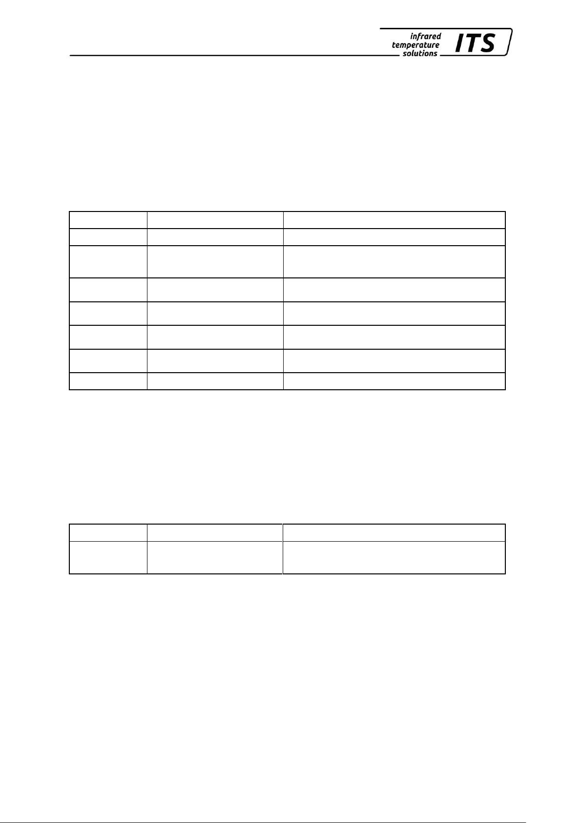
5.1 Configuration I/O (configuration layer: C010)
Parameter
Function
Explanation
AO2.
Analogue output 2
OFF off
AI.FN
Analogue input
function
EPS.Q emissivity ratio
AI.U1
Ain Scaling
Define lower limit of voltage for input voltage
(2 V)
AI.U2
Ain Scaling
Define upper limit of voltage for input voltage
(10 V)
AI.V1
Ain Scaling
Input of lower voltage value
(example 100% emissivity ratio)
AI.V2
Ain Scaling
Input of upper voltage value
(example 110% emissivity ratio)
SAVE
Save
Save changes / exit menu
5.2 Display of internal measured values
According to standard the current temperature is shown in the display of
the pyrometer. Should the current value at the voltage input is to be
shown in the display, change to code page C020 and select parameter
AIN.
Configuration layer: C020
Parameter
Function
Explanation
AIN
Initial value at analogue input
Current value of analogue input

Operating manual VK 30.03
8
6 Shipping, Packaging and Disposal
6.1 Inspecting your shipment
Unpack and inspect the entire shipment immediately upon receipt to
make sure it is complete and undamaged.
If the container/package shows visible signs of damage, please refuse
the shipment. If this is not possible, accept the shipment on the condition
that the freight carrier’s delivery record is noted with the extent of the
damage in order to file a claim.
Should you discover a concealed loss or damage, report it to KELLER
HCW and to the freight carrier immediately. If the period for filing claims
has expired, you will no longer be able to make any claims for compensation of damage or loss.
6.2 Packaging
The packages used by KELLER HCW are made of carefully selected,
environmentally compatible materials and are thus recyclable. We suggest you retain the packaging for possible future use; otherwise please
ensure that they are disposed of in an ecologically sound manner.
6.3 Disposal of used apparatus
Used electrical and electronic equipment often contain valuable components. The owner/user may either return such an instrument to the manufacturer for disposal, or he must dispose of it himself in a professional
and nonpolluting manner.
KELLER HCW will not be held accountable for any inappropriate disposal carried out by the user/owner of KELLER HCW instruments.

Operating manual VK 30.03
9

 Loading...