

Nr. 5005-0100
Nr. 5005-0105
Nr. 5005-0110
Operating Instructions
LOG100/110/CRYO
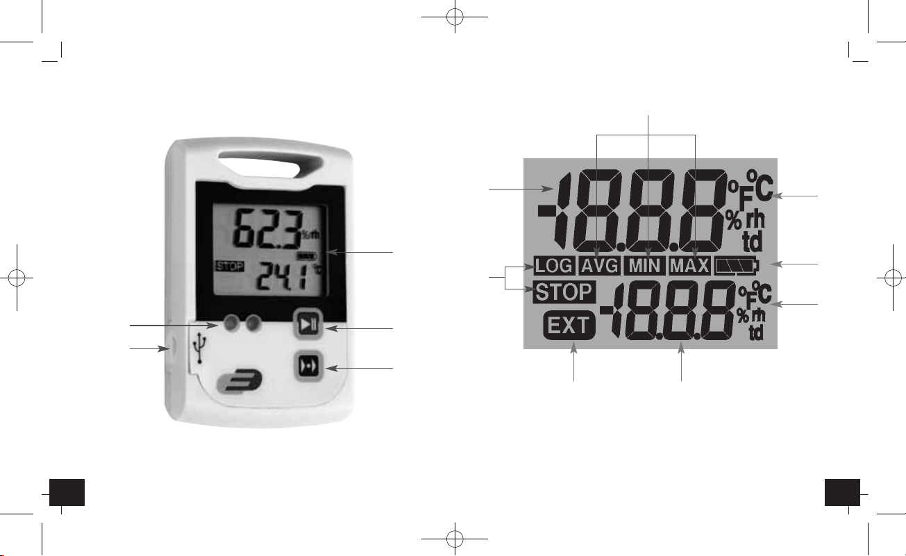
Fig. 1 Fig. 2
D
E
A
F
K
J
G
M
I
H L
B
C
Dear customer,
thank you very much for purchasing one of our products. Before operating
the data logger please read this manual carefully. You will get useful information for understanding all functions.
1.1 General advice
• For cleaning the instrument please do not use an abrasive cleaner only a
dry or wet piece of soft cloth.
• Please store the measuring instrument in a dry and clean place.
• Avoid any force like shocks or pressure to the instrument.
• Do not use force to connect the probe or the interface plugs in. The interface plug is different from the probe plug.
1.2 Before operation
• Before operating the instrument take the instrument out of the packaging. Check whether a full battery CR2032 (3 Volt) is already inserted.
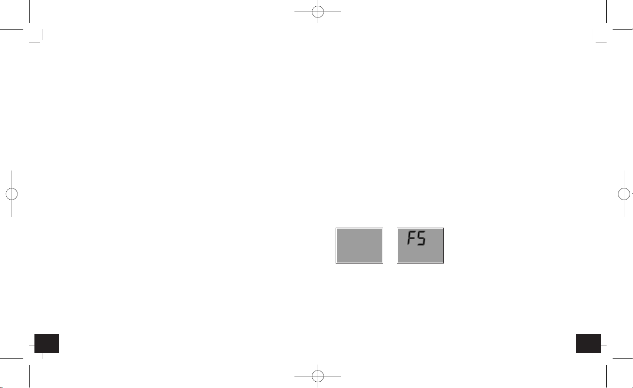
Display Display indication after key depression
indication FS = Factory settings
• After inserting the battery the instrument displays for 10 seconds the actual
measurements, afterwards the instrument displays for 30 seconds “FS”, after
this the instrument turn off. The same procedure appear after pressing any
button.
LOG100/110/CRYO – Data logger
1. Introduction

LOG100/110/CRYO – Data logger
LOG100/110/CRYO – Data logger
1.4. Marking
• Log100/110/100CRYO: CE-conformity
• Log100 only: EN 12830, EN 13485, Suitability for storage (S) and transportation (T) for food storage and distribution(C), Accuracy classification 1
(-30..+70°C), according to EN 13486 we recommend a recalibration once
per year.
2. Operation
• For configuring the data logger, please install the Software DE-LOG-Graph
on a PC.
2.1 USB-Port
• When the Software Installation has been completed please connect the PC
with data logger via USB-cable. For detailed information please read the
manual of the DE-LOG-Graph-Software.
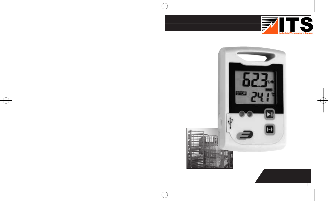
2.2 Panel and display (Fig. 1)
Log100/110/100CRYO have a large display, two LEDs and two buttons.
A: LCD-display indicate humidity, temperature, external temperature(in case
of an external sensor), Low bat-warning, Max-Min-Avg-measurements,
status information
B: Start-Stop-button
C: Mode-button
D: LED: green/red
E: USB-port (with rubber cap)
2.3 Button-handling
• On the front panel there are two buttons. Both buttons can be de activated
by using the Software DE-LOG-Graph, to prevent unauthorized use.
1.3 Standard settings / Factory settings
• Note the following default settings of the data logger before first use. By
using the DE-LOG-Graph software, the setting parameter can easily be
changed:
1. Description: blank (max. 16 characters)
2. LCD-Snooze mode:
3. LCD-Snooze after Sec.: 10
4. Mode-button active:
5. Alarm settings for temperature:
Log100/110: -30,0°C 70,0°C -40,0°C 150,0°C
Log100CRYO: -10,0°C 70,0°C -200,0°C 350,0°C
Alarm settings humidity: 0,0% 100,0% (Log110 only)
6. Alarm delay: □
7. Alarm cumulation: of
f
8. Alarm reset:
9.
Alarm-LED-interval 3 seconds
10.
Alarm-LED-blink duration 1 second
11.
Alarm-Buzzer-interval 30 seconds
12.
Alarm-Buzzer-duration 1 second
13. T
emperature unit: °C
14.
Start-button active:
15. Start by Reed-contact: □ (by request only)
16. Waiting for manual start:
17. Single use only:
18. Measuring interval: 15 Minutes
19. Stop-button active:
20. Stop by Reed-contact: □ (by request only)
21. Cycle memory: (if the memory is full the oldest measurement will be
overwritten)
= Default

LOG100/110/CRYO – Data logger
LOG100/110/CRYO – Data logger
F: Measurement 1 displays the current relative humidity (Log110) or the
current temperature (Log100 / Log100CRYO).
G: Unit Measurement 1 display the current measuring unit of measurement 1.
H: Measurement 2 displays the measurement in the lower display line.
Depending on the logger model, the settings of the internal or the
external temperature measurement, average, minimum or maximum
measurements will be displayed.
I: Unit Measurement 2 display the current measuring unit of measurement 2.
J: MAX-MIN-AVG display the average, minimum or maximum measure-
ments.
K: Status info display the operation mode LOG or STOP. LOG indicates the
recording mode and STOP indicates standby mode.
L: External probe EXT s displayed when an external sensor is connected. In
the lower display line the measurement 2 is corresponding with the
external sensor.
M: Lowbat indicates the capacity of the battery.
Note: °C = Celsius,°F = Fahrenheit
%rh = relative humidity, td = dew point temperature
Other display information
• In addition to the above mentioned information, the display also indicates
several other information. This information will be displayed depending
on the display settings (snooze function) and operation mode:
Display connected
Logger
switched off to the PC configured
• Start-Stop-button:
Depending on the setup configuration, you can start or Stop the data logger via the mentioned Start-Stop-buttons. You have to press and hold the
buttons 3 seconds. When it starts a short acoustic signal and the green LEDwill flash and the display indication will switch from STOP to LOG.
•
Mode-button:
By pressing the Mode-button you will see on the bottom line the A
verage
(AVG)-, Minimum (MIN)- and Maximum (MAX) temperature of the recorded
measurements. If the data logger is not started it will display --- instead of
AVG, MIN or MAX temperature.
A
VG: MIN: MAX: AUT:
Average Minimum Maximum Auto-switch
By using the AUTO-Mode (AUT) the display will switch automatically every
two seconds.
In LOG mode, acoustic alerts can be disabled by pressing the Mode-button
for 2 seconds (Display “Bep Off”).
2.4 Display segments of LCD (Fig. 2)
•
Besides the two measurements, the large LCD displays several status information. By using the Software DE-LOG-Graph you are able to switch on or
off the display, or to setup an interval how long the display will stay on
when no button is pressed (snooze function). By using this function it is possible to prevent it displaying information to unauthorized persons.
➥
➥
LOG100/110/CRYO – Data logger
LOG100/110/CRYO – Data logger
• After the completed communication with the PC do not forget to plug the
rubber cap back into the port. It prevents dirt and water from entering the
data logger.
2.7 External sensor connection
•
Use the USB socket to connect the external temperature sensor. Therefore
remove the rubber cap from the USB socket. Afterwards connect the external probe by use of the socket. The probe will be registered automatically.
•
Note: Using the external temperature sensor the instrument loses the splash
water protection (IP65).
2.8 Rear side of the data logger / battery case
•
On the rear side of the data logger you will find the battery case and a
printed sticker.
2.9 Replacing battery
•
To replace the battery please open the battery cover on the rear side. Therefore you have to turn the battery cover 90° to the left. Remove the battery
from the instrument and replace with a new battery.
•
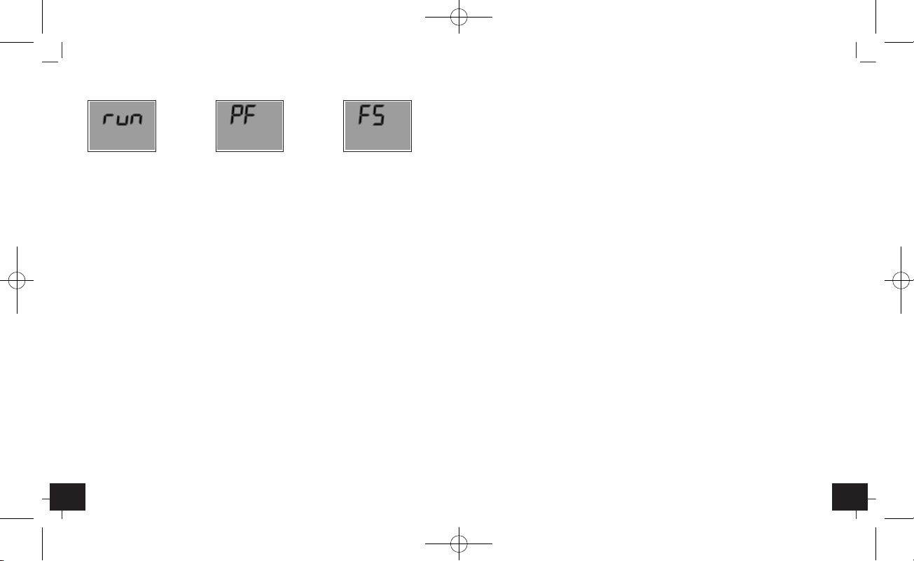
The “BAT “symbol indicates that the battery needs to be exchanged. The
instrument allows app. 10 hours of further operation after displaying the
“BAT“ symbol The battery symbol indicates according to the battery status
between 1 to 3 segments.
•
If the display indicates only “PF“, the battery is completely exhausted.
Please replace the battery immediately.
3.0 Waste disposal
This product has been manufactured using high-grade materials and components which can be recycled and reused.
Logger Battery
Factory settings
is recording (total empty)
2.5 LED-Indication and Buzzer
• The two LED’s and the internal buzzer help you to understand all logger
information, several status modes and alarm indications.
• LED green:
The green LED flashes during the logger start and according to the measuring interval if the standard settings hasn’
t been changed.
• LED red:
The red LED flashes when Hi- or Lo-Alarm has been achieved.
• Buzzer:
The Buzzer rings when Hi- or Lo-Alarm has been achieved(if the buzzer is
not deactivated). The Buzzer also rings when the configuration has been
transferred successful from the PC to the Logger
.
• You can activate or deactivate both, LEDs and Buzzer by using the Software DE-LOG-Graph.
2.6 USB-Port
• For readout or programming, the data logger must be connected via USBcable with a PC.
•
View from the front: On the left side there is the USB-port. The port is protected by a small white rubber cap. To operate the USB-port please remove
the rubber cap.

LOG100/110/CRYO – Data logger
LOG100/110/CRYO – Data logger
Storage temperature -30..+70°C
Dimensions 88 x 55 x 20 mm
Weight 95 g
Power supply 1 x CR2032 3 V
Never dispose of empty batteries and rechargeable batteries in
household waste.
As a consumer, you are legally required to take them to your
retail store or to appropriate collection sites depending on
national or local regulations in order to protect the environment.
The symbols for the heavy metals contained are:
Cd=cadmium, Hg=mercury, Pb=lead
This instrument is labeled in accordance with the EU Waste Electrical and Electronic Equipment Directive (WEEE).
Please do not dispose of this instrument in household waste. The
user is obligated to take end-of-life devices to a designated collection point for the disposal of electrical and electronic equipment, in order to ensure environmentally-compatible disposal.
3.1 Specifications
Data logger Log100 Log100CRYO Log110
Temperature Temperature Temperature
humidity
Internal
temperature probe -30..+70°C -10..+70°C -30..+70°C
External
temperature probe -50..+125°C -200..+350°C -50..+125°C
Relative humidity - - - - - - 0..99%rH
Memory appr. 60.000 Data sets
Interface USB
Working temperature
(without display) -30..+70°C -10..+70°C -30..+70°C
 Loading...