


CGW-T/TS
Analog GSM/CDMA
Cellular Gateway
Installation and
Programming Manual

CGW-T/TS
Installation and Programming Manual
Release 4, Revision 3, July 2008

NOTICE
This manual describes the CGW-T/TS Analog GSM/CDMA Cellular Gateway.
Additional copies of this manual may be obtained from ITS. No part of this document may be
reproduced or transmitted in any form, by any means (electronic, photocopying, recording, or
otherwise) without the prior written permission of ITS.
ITS reserves the right to modify the hardware and software described in the manual without
prior notice. However, changes made to the hardware or software described does not
necessarily render this publication invalid.
WARRANTY
In the event that the product proves to be defective in workmanship or materials within a
period of one year from date of shipment, ITS shall repair or replace the product at its
discretion. Transportation will be the responsibility of the dealer/distributor.
Under no circumstances shall ITS be liable for consequential or special damages, loss of
revenue or user/dealer expenses arising out of or in connection with the use or
performance of the product, whether based on contract, tort, or any other legal
agreement.
The following shall void the above warranty: malfunctions resulting from fire, accident,
neglect, abuse, or acts of God; use of improper electrical power; or repair of, tampering with
or alteration of the product by anyone other than ITS authorized personnel.

Table of Contents
1 Introduction............................................................................................... 3
1.1 Main Features .............................................................................................. 5
1.2 Contents....................................................................................................... 6
2 Physical Description.................................................................................. 7
3 Pre-Installation.......................................................................................... 8
3.1 GSM Gateway ............................................................................................ 8
3.2 CDMA Gateway (CGW-T Only)................................................................. 8
4 Installation ................................................................................................. 9
4.1 SIM Card Insertion into the Unit (GSM only)............................................. 9
4.2 CGW-T/TS Installation.............................................................................. 10
5 LCD Status Indicators and Diagnostics ................................................ 12
5.1 CGW-T LCD Status Indicators and Diagnostics....................................... 12
5.2 CGW-TS LED Status Indicators and Diagnostics ..................................... 16
6 DTMF Programming.............................................................................. 21
7 Technical Data......................................................................................... 30
7.1 CGW-T/TS for GSM Network .................................................................. 30
7.2 CGW-T for CDMA Network..................................................................... 32
8 CGW-T/TS Accessories .......................................................................... 34
2 CGW-T/TS Installation and Programming Manual


1 Introduction
Your new CGW-T is an analog GSM/CDMA Cellular Gateway (CGW-TS – GSM only), a
cost reduction tool for mobile-to-landline and landline-to-mobile calls. It connects from the
trunk interface (analog FXO) of your PBX to a GSM network (via the inserted SIM card) or
to a CDMA network (by the built-in CDMA engine), eliminating the excessive
interconnection fees and significantly cutting your telephone costs.
The Automatic Route Select table (ARS) in the PBX defines which calls will be automatically
routed via the CGW-T to the predefined GSM/CDMA network. In doing so, the CGW-T/TS
gateway reduces the company’s telephone costs.
Installation of the CGW-T/TS does not require special skills. Simply insert the SIM card
(GSM networks only), connect the unit to the PBX trunk interface, attach the antenna and
power supply, and your CGW-T/TS can immediately start saving money for you. The unit has
an LCD display, which shows the GSM/CDMA operator’s name (CGW-T only), the signal
strength and other useful call progress information.
A number of additional parameters for the CGW-T/TS, such as Output Audio Volume level
setting, Conversion time-out and Restricted Digits, can be programmed via DTMF.
The CGW-T and CGW-TS units are displayed in Figure 1.
CGW-T/TS Installation and Programming Manual 3

CGW-T CGW-TS
Figure 1. CGW-T and CGW-TS Devices
4 CGW-T/TS Installation and Programming Manual

1.1 Main Features
The following is a list of Main Features of the CGW-T/TS GSM/CDMA gateway:
Integrated dual-band GSM module (900/1800, 850/1900 MHz) for both
CGW-T/TS or
Integrated dual-band CDMA module (800/1900 MHz) for CGW-T only
Built-in LCD (for CGW-T) or LED indicators (for CGW-TS)
Signal strength indicator
Cellular operator name indicator (for CGW-T only)
Operational status
DTMF programming
• Call Barring (Toll Restriction)
• Conversation Time-Out
• Reverse polarity signaling support
• Audio Volume control
• Roaming Control (GSM only)
• CLIR (GSM only)
Supports DTMF dialing
Line interface, 2-wire (RJ-11 connector)
Plug & Play installation
High voice quality
Maintenance free

1.2 Contents
The contents of your CGW-T/TS package are as follows:
No. Item Qty.
1. CGW-T/TS device 1
2. Installation and Operation Manual 1
3. Power Supply
(Input: 110VAC, 60Hz or 220VAC, 50Hz)
(Output: 9VDC, 13.5W, 800 mA)
4. OMNI Antenna (with cable) 2,5 dB 1
5. RJ-11 telephone cable 1
6. Template for wall mounting 1
7. Screws and plugs for wall mounting 2
6 CGW-T/TS Installation and Programming Manual
1
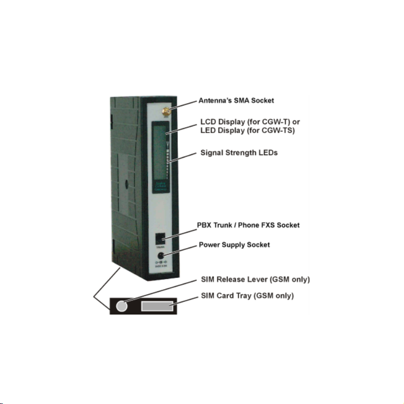
2 Physical Description
The physical features of the CGW-T/TS are detailed in Figure 2.
Figure 2. CGW-T/TS Physical Description

3 Pre-Installation
3.1 GSM Gateway
The CGW-T/TS unit contains a GSM engine. It therefore needs a SIM card from the local
GSM network provider. Its registration to the GSM operator is similar to the registration of a
mobile GSM phone.
The PIN and PUK code requests recommended to be disabled (see LCD Messages table,
below). If, for any reason, you are unable to do so using an analog telephone connected to the
CGW-T/TS FXS RJ-11 port, use any GSM mobile phone to modify the SIM card, or contact
your local GSM Service Center.
3.2 CDMA Gateway (CGW-T Only)
The CGW-T (CDMA) contains a CDMA engine that needs to be activated via a local CDMA
network provider. You register the engine the way you would normally register a mobile
CDMA phone.
NOTE
It is recommended that you disable all call forwarding modes (in the events of busy,
absence, unavailability, etc.) and Call Waiting from the GSM/CDMA operator, before
installing the SIM card (GSM network), or activating the CDMA unit.
8 CGW-T/TS Installation and Programming Manual

4 Installation
4.1 SIM Card Insertion into the Unit (GSM only)
CAUTION
1
The physical description of the unit can be used as guideline for the following steps:
Hold the unit in your hands with the display pointed to your left and the SIM insertion
Using a screwdriver, push the yellow SIM release lever, so that the SIM card tray moves
Take out the tray. You will see that the SIM card fits in the tray in one way only.
Carefully place the tray with the SIM card in the slot and slide it in with the SIM card
To avoid damage to the CGW-T/TS unit, disconnect the 9V adapter from the electric
power outlet.
slot at the bottom of the unit towards you (so that the text “SIM” is upside-down).
towards you.
contacts facing down.

4.2 CGW-T/TS Installation
To install the CGW-T/TS unit, perform the steps as follows:
Mount the CGW-T/TS unit on the wall as a stand-alone unit or on the 6-fold wall mount
bracket, which is a separate accessory.
Connect the antenna into the Ant. connector on the front panel of the CGW-T/TS unit.
Connect the analog trunk interface of the PBX to the trunk connector on the front panel
of the CGW-T/TS unit.
Connect the power supply to the CGW-T/TS unit. The unit will start the initialization
and registration. At the end of the process, the LCD will display the signal status.
NOTE
Figure 3 displays the schematic setup of the CGW-T/TS unit.
Adjust the antenna location until an optimal signal level is received.
10 CGW-T/TS Installation and Programming Manual

Figure 3. CGW-T/TS Schematic Setup
5 LCD Status Indicators and Diagnostics
5.1 CGW-T LCD Status Indicators and Diagnostics
The CGW-T Gateway can be connected to the analog trunk interface of the PBX. At powerup of the CGW-T unit, the information on the LCD will provide the first diagnostics. Usually,
further diagnostics are unnecessary. By connecting an analog telephone with the RJ-11
connector to the trunk connector in the unit, you are able to perform further diagnostics.
5.1.1 LCD Status Indicators
The following table shows the messages appearing on the LCD, their description and the
action to be taken (if any).
LCD Message Description Action
Searching
Network…
Enter PIN code
(GSM only)
12 CGW-T/TS Installation and Programming Manual
Searching for the mobile
network.
CGW-T needs the PIN code
to activate the SIM card.
No action needed.
1. Connect an analog telephone to
the unit and enter the code. (4-8
digits. Add a # to the code when
using less than 8 digits)
2. Alternatively, insert the SIM
into your mobile phone and disable
the security option.

LCD Message Description Action
Enter PUK code
(GSM only)
Registration…
S=X dBm
Name operator
Calling… CGW-T dials to destination. Wait.
Connected When called party answers. No action needed.
Disconnected End of call. No action needed.
Incoming Call
CGW-T received 3 times an
incorrect PIN code.
Registration process after the
mobile network has been
found.
LCD shows signal level in
dBm
Name of Operator (read from
mobile network).
CGW-T gets a call from
network.
Request the PUK code from your
local GSM operator and enter it
into the CGW-T.
Wait till registration phase is
finished.
If level is below 85 dBm, move the
antenna to another location with a
better reception.
No action is needed.
No action needed.

LCD Message Description Action
CGW-T receives incorrect
Failed
operation information from
the mobile network.
Try again.
Engine Problem
No Signal
Reg. Denied
Insert SIM Card
(GSM only)
14 CGW-T/TS Installation and Programming Manual
GSM/CDMA engine
problem.
No Signal or Signal low (less
than 108 dBm).
Registration denied and/or
SIM card is not readable.
No SIM card inserted. Insert SIM card.
Power off and on the unit. If error
is repeated, the unit is faulty.
1. Check your antenna connection.
2. Move your antenna to a location
with a better reception.
3. Check with your GSM operator.
Replace the SIM card.
Contact your GSM operator.

5.1.2 CGW-T Diagnostics
Perform the diagnostic procedure as follows:
Connect an analog telephone directly to the trunk connector (RJ-11) on the unit front
panel.
Pick up the receiver and listen to the dial tone:
- A continuous dial tone indicates that the unit is working correctly and ready for
programming.
- A busy dial tone indicates that there is a fault. Check the LCD display for a
message.
NOTE
If there is no SIM card in the device, or if the card is not installed properly, there will
be no tone on the CGW-T, whereas on the CGW-D the tone will be that of the PSTN
line.

P
5.2 CGW-TS LED Status Indicators and Diagnostics
When you power-up the CGW-TS, the LEDs indicate the first diagnostics. In most cases
further diagnostics are not needed. Figure 4 displays the LED layout on the CGW-TS.
ower
Status
LED #4
LED #3
LED #2
LED #1
Figure 4. LED Layout on the CGW-TS
To perform further diagnostics, connect an analog telephone with an RJ-11 connector to the
trunk connector in the unit. For details on how to perform further diagnostics, see Paragraph
5.2.3.
16 CGW-T/TS Installation and Programming Manual

5.2.1 CGW-TS LED Activity Status Indicators
The LED activity status indicators are detailed in the following table:
LED Status Indicators
Description
Standby Mode On On On On On On
Conversation On On On On On Flashing fast
Incoming Call On On On On On Flashing
Outgoing Call On On On On On Flashing
Programming Mode Off Off Off Off Flashing Off
LED1
Yellow
LED2
Yellow
LED3
Yellow
LED4
Yellow
Power
Green
Status
Red

5.2.2 CGW-TS LED Error Status Indicators
The LED error status indicators are detailed in the following table:
LED Status Indicators
Description
GSM Engine
Problem
Solution
No Signal or
Signal Low
(less than 108 dBM)
Solution
Registration Denied Flashing Off Off Flashing On Off
Solution
18 CGW-T/TS Installation and Programming Manual
LED1
Yellow
Flashing Flashing Flashing Flashing Flashing Flashing
Refer to your local supplier.
Flashing Off Off Off On Off
Check your antenna connection or move your antenna to a location with a better
reception or enable your Roaming parameter (see Paragraph 5.2.3).
Contact your local GSM operator or enable your roaming parameter (see
Paragraph 5.2.3).
LED2
Yellow
LED3
Yellow
LED4
Yellow
Power
Green
Status
Red

LED Status Indicators
Description
Description
PIN Error Off Flashing Off Off On Off
Solution
SIM Card is Not
Readable
Solution
No SIM Card
Inserted
Solution
LED1
Yellow
LED1
Yellow
Dial your SIM card’s PIN code using your phone extension. Once entered using
the phone, the unit will remember the PIN code.
Alternatively, you can remove the SIM card from the CGW-TS and disable the
PIN number using your mobile phone, then put it back inside the unit.
Off Off Flashing Off On Off
Check the SIM position or replace the SIM card or contact your local operator.
Off Off Off Flashing On Off
Insert the SIM card.
LED2
Yellow
LED Status Indicators
LED2
Yellow
LED3
Yellow
LED3
Yellow
LED4
Yellow
LED4
Yellow
Power
Green
Power
Green
Status
Red
Status
Red

5.2.3 CGW-TS Diagnostics
Perform the diagnostic procedure as follows:
Connect an analog telephone directly to the trunk (FXS) connector (RJ-11) on the unit
front panel.
Pick up the receiver and listen to the dial tone:
- A continuous dial tone indicates that the unit is working correctly and ready for
programming.
- A busy dial tone indicates that there is a fault. Check which LEDs are lit and find
the error in the table in Paragraph
resolve the problem and hear a continuous dial tone.
- No dial tone indicates that the GSM network signal is too low to complete
registration. Remove your SIM card and replace it with a card from a GSM
network that provides a higher signal level. Enable the roaming parameter (see
command *500 in the programming table), and then replace the SIM card with your
original SIM card.
NOTE
All cellular calls you now make from your CGW-TS will be routed through the
alternate GSM network that you used to complete your registration.
5.2.2. You cannot program the unit until you
20 CGW-T/TS Installation and Programming Manual

6 DTMF Programming
The CGW-T/TS Gateway can be programmed via DTMF. To program the unit perform the
steps as follows:
a. If the unit is connected to the PBX, remove the cable from the Trunk connector on the
unit front panel.
b. Connect an analog telephone directly to the Trunk connector.
c. Dial *900 and enter the password (1234 by default).
d. Use the commands in the following table for programming.
NOTE
When DTMF programming changes are made, the device will perform an
automatic reset for the changes to take effect.
The CGW-T/TS will not answer incoming calls in the programming mode.
Exit from the programming mode by *900 or hanging up the telephone.
If you do not enter digits for 45 seconds, the unit will automatically exit the
programming mode.
When entering an incorrect command, you will hear a beep.
When entering a correct command, you will hear two beeps.

Operation Command Default
Enter the Programming
mode
Exit the Programming
mode
Maximum number of
digits to be dialed by the
CGW-T
Note
:
Less than XX digits –
there will be a time-out of
3 seconds (default),
before the dialing starts.
Exactly XX digits – the
number will be dialed
directly.
More than XX digits –
the number will be cut off
after XX has been
reached.
*900 + XXXX
where:
XXXX = Password (1234
default)
*900
*300 + XX
where:
XX = 05-20 (digits)
1234
11 (Tip: set the default to
country’s max. telephone
number length.)
22 CGW-T/TS Installation and Programming Manual

Operation Command Default
Time-out value in
seconds. When an
insufficient number of
digits are dialed, this
defines the period of time
that the device will wait
until timeout (inter-digit).
Reverse Polarity
The unit may be set up to
send a “reverse polarity”
command to the PBX, in
case a “call answer” is
detected. This parameter
is useful if call
accounting software is
active.
Output Volume Control *330 + X
*310 + X
where:
X = 2 - 9
*320 + X
where:
X = 0 – 2
0 = No reverse polarity
1 = Reverse polarity only on
Outgoing calls
2 = Reverse polarity for
Incoming and Outgoing Calls
where:
X = 0 – 7 (CDMA)
X = 0 – 9 (GSM)
3 (sec.)
2
5

Operation Command Default
CGW-T Telephone
Number (CGW-T only)
Enter the SIM telephone
number to be displayed
on the LCD during
power-up of the unit.
(GSM only)
DTMF support option
(CDMA only)
Verification of the
Telephone Number
(CGW-T only)
Display the SIM
telephone number on the
LCD for 5 seconds when
in programming mode.
(GSM only)
Conversation Time-Out
The telephone
conversation will be
automatically terminated
after this time-out.
*350 + Number + #
where:
Number = SIM Telephone
number (up to 15 digits)
*350 + X, where:
X = 1 enabled; X = 0 disabled
*360
*390 + XX
where:
XX = number of minutes
00 = unlimited
None
00 (unlimited)
24 CGW-T/TS Installation and Programming Manual

Operation Command Default
End Dialing Digit
Define "#" as the digit
that indicates the end of a
dialed number, causing
the unit to immediately
start dialing.
(GSM only)
Pulse drop (Loop
Disconnect)
Activate the pulse drop
feature by defining time
for loop disconnect for
conversation end state
signaling to PBX.
*370 + X
where:
X = 0 End dialing digit
disabled
X = 1 End dialing digit
enabled
("#" indicates end of number)
*380 + XX
where:
XX = time in tenth of seconds.
For example:
X = 10=1000 milliseconds = 1
second
X = 01 = 100 milliseconds
Legal values: 00-99
Note: If this feature is activated
together with reverse polarity
(*320) 'Pulse drop' occurs after
polarity is reversed.
1
00
(Feature disabled)

Operation Command Default
Call barring (number of
restricted prefixes).
Delete Call Barring (Toll
Restriction).
Cellular Engine Reset
Interval
Define the interval, in
hours, between cellular
channel resets. Reset is
always performed when
the unit is in Idle mode.
Reset affects the GSM
engine only, and does not
affect any of the
parameters.
*400 + XX + YYYY + #
where:
XX = 01 to 10 (list of restricted
prefixes – up to 4 digits)
*400 + XX + # (delete prefix
entry) or
*400 + # (delete the whole
restricted prefixes list)
*450 + XX
where:
XX = number of hours between
resets (01 to 99; 00 indicates no
reset at all)
None
None
00
(reset disabled)
26 CGW-T/TS Installation and Programming Manual

Operation Command Default
Roaming
The unit will be able to
register with another
GSM operator.
(GSM only)
Busy Detect Timer – time
interval for busy tone
detection. The device
disconnects when a busy
tone is detected for XX
seconds
Tone Detect Timer – time
interval for continuous
tone detection. The
device disconnects when
a continuous tone is
detected for XX seconds
*500 + X
where:
X = 0, off
X = 1, on
*520 + XX
Where XX – time in seconds
(an error rate of ±25% may
occur due to busy tone
cadence).
*530 + XX
Where XX – time in seconds
(an error rate of ±25% may
occur due to tone flexibility).
0
6
6

Operation Command Default
No Voice Detect Timer –
time interval for silence
detection. The device
disconnects when silence
is detected for XX
minutes
CLIR (Calling Line
Interface Restriction)
The CGW-T can be
restricted to show its SIM
telephone number.
(GSM only)
Change programming
password
Reset the unit and set to
default values
*540 + XX
Where XX – time in minutes.
*550 + X
where:
X = 0, off
X = 1, on
*600 + new password
where: password must be 4
digits (only digits 0-9)
*151
99
1 – Basic version.
In some types the default
is 0 – contact your local
distributor.
1234
28 CGW-T/TS Installation and Programming Manual


7 Technical Data
7.1 CGW-T/TS for GSM Network
Model CGW-T GSM Gateway
GSM Network Type GSM Phase II
GSM Module Integrated dual-band (900/1800, 850/1900 MHz)
SIM card Plug-in, 3V, small
Transmission Power
Receiver sensitivity -104 dBm
Connectors
Max. 2W / 900MHz
Max. 2W / 850MHz
Max. 1W / 1800MHz
Max. 1W / 1900MHz
RJ-11 (Trunk) – to analog PBX trunk interface
Power Supply
SMA female - Antenna
Off-hook AC impedance 600Ω
On-hook line voltage 48VDC
Off-hook line current Maximum 25mA
30 CGW-T/TS Installation and Programming Manual

Off-hook loop resistance
threshold
Dial tone frequency 400Hz
Ringing voltage 48Vrms, 25Hz
Supported dialing type DTMF
800Ω
Antenna
Antenna cable length 2m / 9.8ft
Power supply
Temperature range
Maximum relative humidity 95%
Dimensions (HxWxD) 212x44x121 mm/8.3x1.7x4.8 inch
Weight 550g (1.21 lbs)
50Ω Impedance, connected via SMA connector
frequency 800 - 2000MHz
Input: 110VAC, 60Hz
220VAC, 50Hz
Output: 9VDC, 800mA
0˚C-45˚C
32˚F-113˚F

7.2 CGW-T for CDMA Network
Model CGW-T CDMA Gateway
CDMA Network Type CDMA, CDMA 1X
CDMA Module
Transmission Power Max 800MHz = 1/4W
Receiver sensitivity Digital <-104 dBm
Connections
Integrated dual-band Tri-Mode (CDMA 1X 800/1900MHz,
AMPS 800MHz)
Analog <-116 dBm
To analog trunk interface of PBX – RJ-11
(Trunk) (operational mode)
To analog telephone – RJ-11 (Trunk)
(programming mode)
Power Supply
Antenna
Off-hook AC impedance 600Ω
On-hook line voltage 48VDC
Off-hook line current Maximum 25mA
Off-hook loop resistance
threshold
32 CGW-T/TS Installation and Programming Manual
800Ω

Dial tone frequency 400Hz
Ringing voltage 48Vrms, 25Hz
Supported dialing type DTMF
Antenna
Antenna cable length
Temperature range
Maximum relative humidity 95%
Dimensions (HxWxD) 212x44x121 mm/8.3x1.7x4.8 inch
Weight 550g (1.21 lbs)
Power supply
50Ω Impedance, connected via SMA connector
frequency 800/1800/1900MHz
3m
9.8ft
0˚C-45˚C
32˚F-113˚F
Input: 110VAC, 60Hz
220VAC, 50Hz
Output: 9VDC, 800mA

8 CGW-T/TS Accessories
Your CGW-T/TS package contains a multiple-antenna holder that can hold up to six
antennas, and wall mount brackets for three or six units (Figure 5).
Multiple-Antenna Holder
Three-Unit Bracket
Six-Unit Bracket
Figure 5. CGW-T/TS Mounting Accessories
34 CGW-T/TS Installation and Programming Manual
 Loading...