

Page 1
V8.5e
User Guide
www.isys-group.com
iSys - The Imaging Systems Group Inc. © Copyright 2010 Rev 003
Page 2

COPYRIGHT NOTICE
This document is copyrighted by The Imaging Systems Group Inc., 2000. No part of this publication may be
reproduced, transmitted, transcribed, or stored in a retrieval system of any kind without prior written permission of
The Imaging Systems Group Inc.
TRADEMARKS
Centronics is a U.S. registered trademark of Centronics Data Computer Corporation. Versatec is a registered
trademark of Versatec Corporation.
DISCLAIMER
The Imaging Systems Group Inc. makes no warranties as to the accuracy, validity or fitness for use of the contents
of this manual. The Imaging Systems Group Inc. reserves the right to revise the information in this manual at any
time without notice.
HAFTUNGSAUSSCHLUSS
Imaging Systems Group Inc. übernimmt keinerlei Garantie hinsichtlich der Genauigkeit, Gültigkeit und
Anwendbarkeit dieses Handbuches. Imaging Systems Group Inc. behält sich das Recht vor, die in diesem
Handbuch enthaltenen Informationen jederzeit ohne vorherige Ankündigung zu ändern.
ATTENTION: The V8.5e plotter generates, uses and can radiate radio frequency energy and, if not installed and
used in accordance with the instruction manual, may cause interference to radio communications. It has been
designed to comply with the requirements for Class A computing devices pursuant to Sub-part J of Part 15 of FCC
Rules, which are designed to provide reasonable protection against such interference when operated in a
commercial environment. Operation of this equipment in a residential area is likely to cause interference in which
case, the user, at his own expense, will be required to take whatever measures may be required to correct the
interference.
ACHTUNG: Der V8.5e Plotter erzeugt, verwendet und verbreitet Hochfrequenzenergie und kann daher, im Falle,
dass er nicht gemäß dem Benutzerhandbuch installiert und benutzt wird, zu Störungen im Hochfrequenz
Kommunikationsverkehr führen. Er wurde gemäß den Anforderungen für Rechnergeräte der Klasse A konstruiert
und erfüllt Unterabsatz J des Teils 15 der FCC Vorschriften, die dazu gedacht sind, einen angemessenen Schutz bei
Einsatz dieser Geräte in einer gewerblichen Umgebung zu sichern. Ein Einsatz dieser Geräte in Wohngebieten wird
wahrscheinlich Störungen verursachen, im welchem Falle der Benutzer auf eigene Kosten die notwendigen
Maßnahmen ergreifen muß, die erforderlich sind, um solche Störungen zu vermeiden.
Caution! – must be observed to avoid loss or damage to your equipment.
Important: - must be observed to avoid operational impairment.
Do not proceed past any of the above notices, until you have fully understood the implications.
2
Page 3

Electromagnetic Compatibility (EMC) USA – This equipment generates and radiates radio frequency energy
and if not installed and used in accordance with the instruction manual, may cause interference to radio
communications. It has been tested and found to comply with the limits for a Class A computing device pursuant
to Subpart B of Part 15 of FCC rules, which are designed to provide reasonable protection against such
interference when operated in a commercial environment. Operation of this equipment in a residential area is
likely to cause interference in which case the user at his own expense will be required to take whatever measures
may be required to correct the interference. Shielded cables should be used with this unit to ensure compliance
with the Class A limits.
Europe – This digital equipment fulfils the requirements for radiation emission according to limit B of EN55022/A1
May 1998, and the requirements for immunity according to EN55024 1998 residential, commercial, and light
industry (Compliance is not valid for unshielded network and printer cables).
Vorsicht! – Muss befolgt werden, um Totalverlust oder Beschädigung des Gerätes zu vermeiden.
Wichtig: - Muss befolgt werden, um Beeinträchtigungen beim Betrieb zu vermeiden.
Bitte verfahren Sie erst dann weiter, wenn Sie die Bedeutung der vorstehenden Hinweise vollständig verstanden
haben.
Elektromagnetische Kompatibilität (EMC) USA – Dieses Gerät erzeugt und verbreitet Hochfrequenzenergie
und kann daher, sofern es nicht gemäß dem Benutzerhandbuch installiert und benutzt wird, zu Störungen im
Hochfrequenz-Kommunikationsverkehr führen. Es wurde gemäß den Einschränkungen für Rechnergeräte der
Klasse A konstruiert und erfüllt Unterabsatz J des Teils 15 der FCC Vorschriften, die dazu gedacht sind, einen
angemessenen Schutz bei Einsatz dieser Geräte in einer gewerblichen Umgebung zu sichern. Ein Einsatz dieser
Geräte in Wohngebieten wird wahrscheinlich Störungen verursachen, im welchem Falle der Benutzer auf eigene
Kosten die notwendigen Maßnahmen ergreifen muss, die erforderlich sind, um solche Störungen zu beheben. Um
die Einhaltung der Klasse-Aeinschränkungen zu gewährleisten, sollte das Gerät mit geschirmten Kabeln verwendet
werden.
Europa – Dieses digitale Gerät entspricht den Anforderungen für Strahlungsemissionen gemäß EN55022/A1 Klasse
B vom Mai 1998, sowie die Anforderungen für Störsicherheit gemäß EN55024 1998 für den häuslichen,
gewerblichen und leichtindustriellen Gebrauch (Konformität gilt nicht für ungeschirmte Netz- und Druckerkabel).
3
Page 4

LIMITATION OF LIABILITY
The Imaging Systems Group’s total liability to the purchaser, or to any third party, for damages from any and all
causes whatsoever, regardless of the form of action, whether in contract or in tort, including negligence, and any
infringement of proprietary rights or any misappropriation or unlawful use of any proprietary rights or property of
any third party shall, in the aggregate, be limited to purchase price actually paid by the purchaser for the product
relating to the damages. The limitation of liability provisions of this agreement reflect an informed voluntary
allocation of the risks (known and unknown) that may exist in connection with the provisions of the goods and
services provided hereunder by The Imaging Systems Group Inc., and that such voluntary risk allocation
represents a fundamental part of the agreement reached between The Imaging Systems Group Inc. and the
purchaser. The Imaging Systems Group Inc. shall not be liable for any special, direct or indirect, incidental,
consequential, exemplary, punitive or any similar or other damages of any nature suffered by the purchaser
whatsoever including, without limitation, loss of use or lack of availability of the purchaser facilities, including its
computer resources and any stored data, loss of profits or revenue, or other commercial loss, or any claim for
contribution or indemnity in respect of any claims against the purchaser, regardless of whether The Imaging
Systems Group Inc. has been advised of the possibility of such damages.
The Imaging Systems Group Inc.
911 28th Street N.E.
Calgary, Alberta T2A-7X1
Canada
Phone 1-866-415-4797
Fax: (403) 204-1971
e-mail: support@isys-group.com
http://www.isys-group.com
4
Page 5

TABLE OF CONTENTS
1.1 GENERALDESCRIPTION...................................................................................................................................8
1.2 MEDIADESCRIPTION.......................................................................................................................................8
1.3 ABOUTTHISMANUAL.....................................................................................................................................8
2.1 FUNCTIONAL.................................................................................................................................................10
Operation...............................................................................................................................................................10
Media.....................................................................................................................................................................11
Thermalprinthead..................................................................................................................................................11
Transport................................................................................................................................................................12
2.2 ELECTRICAL....................................................................................................................................................12
Interface.................................................................................................................................................................12
Powerconsumption...............................................................................................................................................12
Powerrequirements
2.3 PHYSICAL.......................................................................................................................................................12
Dimensions.............................................................................................................................................................12
Weight............................................................................................................................... .....................................12
2.4 ENVIRONMENTAL..........................................................................................................................................13
Temperature..........................................................................................................................................................13
Other......................................................................................................................................................................13
3.1UNPACKING............................................................................................................................... ...................14
3.2 MOUNTINGANDPOSITIONING.....................................................................................................................15
3.3 INTERFACESETUP..........................................................................................................................................15
3.4 MEDIAINSTALLATION...................................................................................................................................15
Installingrolledpaper...............................................................................................................................
Installingfan‐foldpaper.........................................................................................................................................18
Installingandusingfilm..........................................................................................................................................18
Installingrolledfilm................................................................................................................................................19
..............................................................................................................................................12
.............16
4.1 POWERSUPPLYPRECAUTIONS.....................................................................................................................21
4.2 USINGTHECONTROLPANEL.........................................................................................................................21
4.3 CONTROLPANELFUNCTIONSANDSETTINGS...............................................................................................23
Changingfunctionsettings.....................................................................................................................................23
5
Page 6

DefaultSettings......................................................................................................................................................23
Testplot..................................................................................................................................................................23
Contrast..................................................................................................................................................................23
Speed......................................................................................................................................................................24
Media.....................................................................................................................................................................24
Scaling.....................................................................................................................................................................25
Emulation(verticalresolution)...............................................................................................................................25
Formfeedlength....................................................................................................................................................25
Bytesperscan........................................................................................................................................................26
Grayscalemediatablenumber..............................................................................................................................27
SetupheadersforprogrammingtheV8.5e
4.4 ERRORMESSAGES.........................................................................................................................................29
4.5 DRIVERINSTALLATION..................................................................................................................................30
5.1 INTRODUCTION.............................................................................................................................................39
5.2 PLOTTERFUNCTIONSANDFEATURES...........................................................................................................39
THEORYOFOPERATION.........................................................................................................................................40
5.3 INTERFACE.....................................................................................................................................................41
Interfacetimingandsignals...................................................................................................................................41
Datarates...............................................................................................................................................................42
Scanwidth..............................................................................................................................................................43
Verticalresolution..................................................................................................................................................43
Scaling.....................................................................................................................................................................43
Printmode..............................................................................................................................................................43
5.4 THERMALPRINTHEAD...................................................................................................................................43
AutomaticHeadTemperatureFeedback...............................................................................................................44
...........................................................................................................27
Filmmedia..............................................................................................................................................................44
5.5MEDIASENSORS...........................................................................................................................................44
6.1 MAINTENANCE............................................................................................................................... ...............45
6.2 MAINTENANCEGUIDELINES..........................................................................................................................46
6.3 REGULARMAINTENANCE..............................................................................................................................46
Cleaningthe
thermalprinthead............................................................................................................................. 47
6
Page 7

Cleaningtheplatenroller............................................................................................................................... ........48
Replacingthefuse..................................................................................................................................................48
7.2 PROBLEMS.....................................................................................................................................................49
Plotterdoesnotplot..............................................................................................................................................49
Plothasverticalwhitestripes................................................................................................................................50
Plotisblotchyorfaded..........................................................................................................................................51
Plotcontrastisweak..............................................................................................................................................51
Plothasblackverticallines....................................................................................................................................
Plotiswronglength................................................................................................................................................52
Paperiswrinklingortearingalongoneedge.........................................................................................................53
Plotterhasnopower..............................................................................................................................................53
Plotterdisplayisfunctioningbutmotordoesnotfunction...................................................................................53
Can’tmakechangestocontrolpanelsettings.......................................................................................................53
Plotoutputspeediserratic....................................................................................................................................
Burningsmellduringplot,or“blooming”presentonoutput................................................................................54
Formfeedstopsbeforedesiredlength..................................................................................................................55
Formfeeddoesnotstopattop‐of‐formmarks.....................................................................................................55
Plotisskewedorunreadable............................................................................................................................... ..55
8.0WARRANTY.......................................................................................................................................................56
A. APPENDIX.............................................................................................................................................................57
ASCIITABLES
B.APPENDIX.............................................................................................................................................................58
...........................................................................................................................................................57
52
54
INTERFACECONNECTORPINASSIGNMENT...........................................................................................................58
C.APPENDIX.............................................................................................................................................................59
CENTRONICSINTERFACEBOARD...........................................................................................................................59
7
Page 8

1. INTRODUCTION
1.1 GENERAL DESCRIPTION
The Imaging Systems Group’s V8.5e Thermal Plotter is a high-sp eed plotter suitable for office or field use. Its
small size and lightweight, yet rugged construction makes it durable in mobile situations. The V8.5e uses direct
thermal plotting technology, so it requires no liquid or powdered ink.
Interface parameter settings and other menu functions can be accessed from either the front panel or the host
computer. It is capable of printing at four speeds; 1.0, 2.0, 3.0, and 4.0 inches per second.
The V8.5e thermal plotter contains a completely new method of plotting rasterized data. Each scan of data plotted
can contain as many as 64 independent intensity levels (gray scales). The thermal print head (TPH) in the V8.5e is
made up of 1728 thermal heater
nibs, and each one of these nibs can be heated to a different energy level, producing a dot on the thermal media
of varying intensity. This type of plotting can produce high-resolution images containing many shades of gray.
The V8.5e prints in both raster and character modes, and contains a 96-character ASCII set. It interfaces with
Versatec and optionally Centronics data interfaces.
1.2 MEDIA DESCRIPTION
The V8.5e uses rolled or fan-folded thermal paper or rolled film. Media width is 8.75, and 9.0 inches. The V8.5e
accommodates regular thermal paper, papers with a protective top coating, as well as certain types of film media.
Call your Imaging Systems Group product representative for media recommendations.
An optional fan-fold paper guide and feeder trays (which attach to the back of the plotter, and below the
rackmount plotter) are available from The Imaging Systems Group which stabilizes the paper for smooth intake of
fanfold papers. These options are useful in field situations or where vibration is a problem.
1.3 ABOUT THIS MANUAL
Please read this manual before using the plotter, in particular the Installation and Operation Chapters, and the
“Regular Maintenance” section in the Maintenance Chapter. Pay special attention to warnings, cautions and notes.
The following conventions are used in this manual:
CAUTION: Indicates possible equipment damage unless procedure is followed correctly.
VORSICHT: Verweist auf die Gefahr der Beschädigung des Gerätes, falls die Vorschriften nicht genau befolgt
werden.
NOTE: Indicates a general rule for a procedure, or an exception to a rule.
WICHTIGER HINWEIS: Verweist auf allgemeine Verfahrensvor schriften oder eine Ausnahme zu einer Vorschrift.
8
Page 9

This symbol indicates an area of possible concern due to static discharge
into the circuitry. When this symbol appears in the manual, please
observe proper static precautions to minimize damage to the circuitry.
Dieses Symbol warnt davor, dass es in diesen Bereichen möglicherweise zu statischen Entladungen an den
Schaltkreisen kommen kann. Wenn dieses Symbol im Handbuch erscheint, sind die entsprechenden
Vorsichtsmaßnahmen zu treffen, um eine Beschädigung der Schaltkreise so weit wie möglich zu vermeiden.
9
Page 10

2. SPECIFICATIONS
2.1 FUNCTIONAL
Operation
Command panel Front mounted.
LED display.
Three push buttons.
Online/Offline, Data and error LED’s.
Command modes Bimodal Plotting mode.
Grayscale mode.
Printing mode.
Features Bimodal (black and white) plotting.
Grayscale plotting.
Plot speed up to 4.0 inches per second.
Microprocessor controlled.
Automatic head temperature feedback
Panel settings ~ On-line, off-line.
~ Test plot, test print.
* Contrast C1, C2, C3, C4, C5, C6, C7, C8.
* Plot speed select 1”, 2”, 3”, 4” per second.
* Media select LP, HP, LF, HF.
~ Scaling (positive and negative) S0, S1, S2,
S3, S4, S5, S6, S7, S8, S9, SA, SB, SC, SD, SE.
~ Vertical emulation.
P0, n0 for 200 dots per inch vertical emulation.
P3, n3 for 203 dots per inch vertical emulation.
P selects positive scaling, n selects negative scaling.
Form feed adjust F2, F4, F8, tF, PF – selects Form feed of 2, 4, 8 inches, Top of Form
sensing, and programable past top of form respectively.
~ Bytes per scan b1, b2 - selects 216 and 264 bytes per scan respectively.
~ Grayscale levels per scan g1, g2, g3, g4 - selects 8, 16, 32, and 64 levels of gray levels
per scan respectively.
~ Grayscale media calibration table number t1, t2.
Settings marked with (*) are used exclusively with bi-modal plotting.
Settings marked with (#) are used exclusively with grayscale plotting.
Settings marked with (~) are used with both bi-modal and grayscale
plotting.
10
Page 11

Plot speeds Paper 1.0, 2.0, 3 .0, and 4.0 inches per second in bimodal (black and white) plotting
mode.
Film: 1.0 inch per second.
Grayscale: dependent upon the number of levels of grayscale selected.
Condition detection Media out.
Top of form.
Head temperature.
24 volt error detection.
Media
Types Thermal sensitive paper or film.
Rolled paper with 7/16 inch spool core.
Rolled film.
Fan-folded paper (optional).
Width 8.75 inch rolled paper or film media.
8.75, 9.0 inch fan fold paper media.
Maximum length Rolled media: 100 feet with thick paper, 150 feet with thin paper. Maximum diameter 2.5
inches. Fan-fold: unlimited maximum.
Fan-fold guides Optional, for fan-fold paper. Adjustable for 8.75 inch and 9.0 inch media.
Feeder trays Optional, for fan-fold paper.
Thermal printhead
Type Linear array.
Resolution 203 dots per inch (8 dots per millimeter).
Dots per scan 1728 (metric) maximum.
Bytes per scan 216 bytes maximum.
Image width 8.5 inches.
11
Page 12

Transport
Stepper motor Micro-step.
Stepping resolution 0.004 millimeter.
6400 micro-steps per inch of media.
32 micro-steps per scan line.
2.2 ELECTRICAL
Interface
Type Parallel, 8 KB buffer
Compatibility Versatec Greensheet
Centronics parallel (optional)
External SCSI
Data cable Optional
Power consumption
Idle mode 110 Watt minimum.
Plot or print mode 365 Watt maximum
Power requirements
Voltage Auto selectable input 100 Volts AC @ 60
Hertz or 240 Volts AC @ 50 Hertz
Current 5 Amps maximum @ 110 Volts
2.5 Amps nominal @ 220 Volts
Fuse 250 Volts / 5 Amps
2.3 PHYSICAL
Dimensions
Rackmount Desktop
Height 3.5 inches 3.5 inches
Width 19 inches 15 inches
Depth 12.5 inches 12.5 inches
Weight
Rackmount Desktop
Net 23 pounds 22 pounds
12
Page 13

2.4 ENVIRONMENTAL
Temperature
Operating range 32º to 122º Fahrenheit (0º to 50º Celsius)
Storage range 14º to 158º Fahrenheit (-10º to 70º Celsius)
Other
Operating humidity 5% to 95 non-condensing
Certification FCC Class “A” CE and cTUVus
13
Page 14
3. INSTALLATION
3.1 UNPACKING
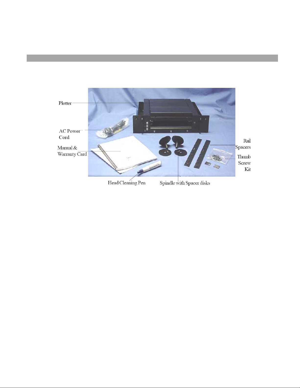
Although shipments are thoroughly checked for completeness by The Imaging Systems Group Inc., please confirm
your plotter contains the following:
1. Power cord
2. Sample Roll of paper
3. Two spindle hubs
4. Rackmount spacers
Confirm that any specified options are present, such as a data cable or fan-fold guide.
AC Power
Cord
Manual & Warranty Card
Head Cleaning Pen
Plotter
Rail
Spacers
Spindle with Spacer disks
Thumb
Screw
Kit
14
Page 15

Inspect the plotter and components for any damage that may have occurred during shipment. Report any damage
to the carrier of the shipment, and to your Imaging Systems Group Inc. product representative.
Keep the box and packaging for future shipping, in the event of servicing or upgrading issues. This product must
be returned to our factory in the original or proper packaging material. Damage caused during return shipping or
due to improper packaging will not be covered by The Imaging Systems Group Inc. During shipping or storage,
place a length of thermal paper between the printhead and roller. This prevents damage caused by the two
components sticking together.
3.2 MOUNTING AND POSITIONING
Keep the V8.5e away from direct heat sources, including sunlight. Do not block the vents on the sides of the
plotter.
CAUTION: Make sure the thumbscrews are secured before operation. This is particularly important in mobile
situations. Damage to the plotter or rack components could result if the plotter becomes unstable.
VORSICHT: Versichern Sie sich vor dem Betrieb des Gerätes, dass die Flügelschrauben festgestellt sind. Das ist
besonders in beweglichen Konstellationen wichtig. Sollte der Plotter instabil werden, kann dies zu Schäden am
Plotter oder am Gestell führen.
3.3 INTERFACE SETUP
Plug the power cord into a grounded AC outlet only. Avoid sharing an outlet that is also powering other noisegenerating equipment. The V8.5e comes equipped with a Versatec short line TTL (transistor to transistor logic)
interface. This interface can be used for data cable lengths up to 50 feet.
An optional long line interface (differential) can be used for data cable lengths up to 700 feet. For optional
Centronics interface setup, see Appendix C. An external SCSI (Small Computer System Interface) is also available.
Please contact your Imaging Systems Group Inc. product representitive for further information.
3.4 MEDIA INSTALLATION
CAUTION: Do not attempt to plot or form feed without the print medium installed. This may damage the print
head and will void the warranty.
VORSICHT: Versuchen Sie bitte nicht, einen Druckvorgang oder Papiervorschub zu starten, wenn sich kein
Druckmedium im Plotter befindet. Dies kann zu einer Beschädigung des Druckkopfes und zum Verlust der Garantie
führen.
15
Page 16
Installing rolled paper
The V8.5e plotter comes with a sample roll of thermal sensitive paper. To install rolled paper:
1. Loosen the rackmount thumbscrews and pull the plotter forward on the rails.
2. Release the lid assembly by grasping underneath the black latch bar and pulling it upwards (Figure 3-5).
Open the plotter lid by lifting the guide straight upwards.
3. Remove the fan-fold guide by grasping the two stainless steel rails and lifting it straight upwards.
4. Place the spindle hubs onto each end of the roll of media with the spacer on the left hand side spindle.
5. Orient the roll so that the paper feeds off of the top of the roll.
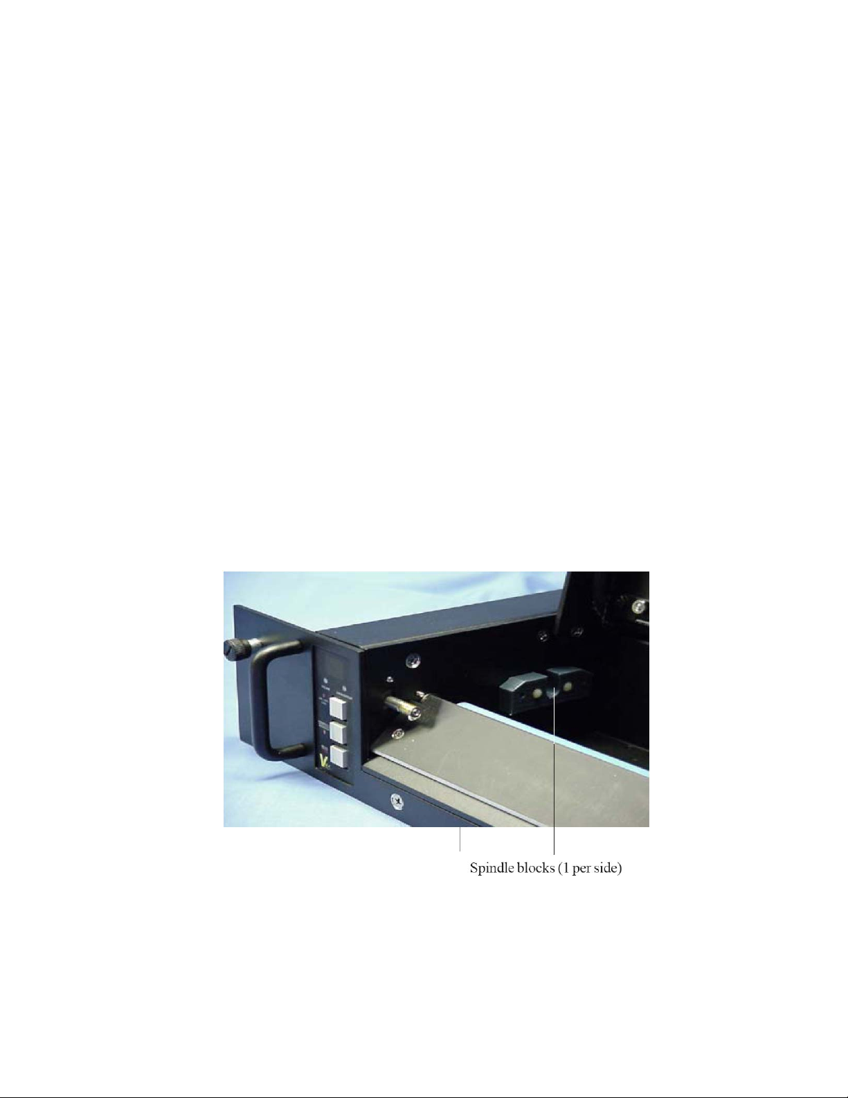
6. Place the roll in the plotter so that the pins on the spindle hubs snap into the slots on the spindle blocks.
7. Guide the paper over the blue platen roller and under the black cutter bar as shown in Figure 3-3.
8. Figure 3-4 shows roll paper installed. When installing any media, ensure that the coated side of the media is
on top.
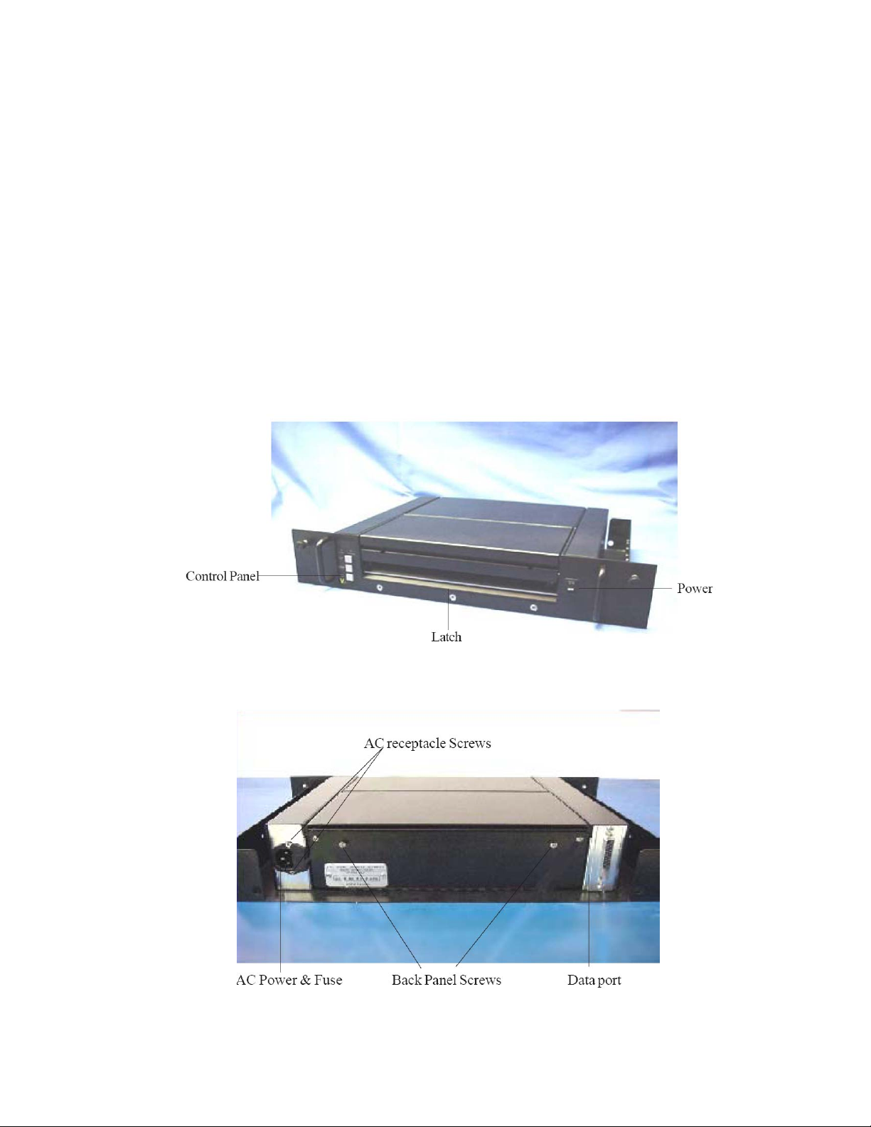
Figure 3-1
Figure 3-2 Back Panel
16
Page 17
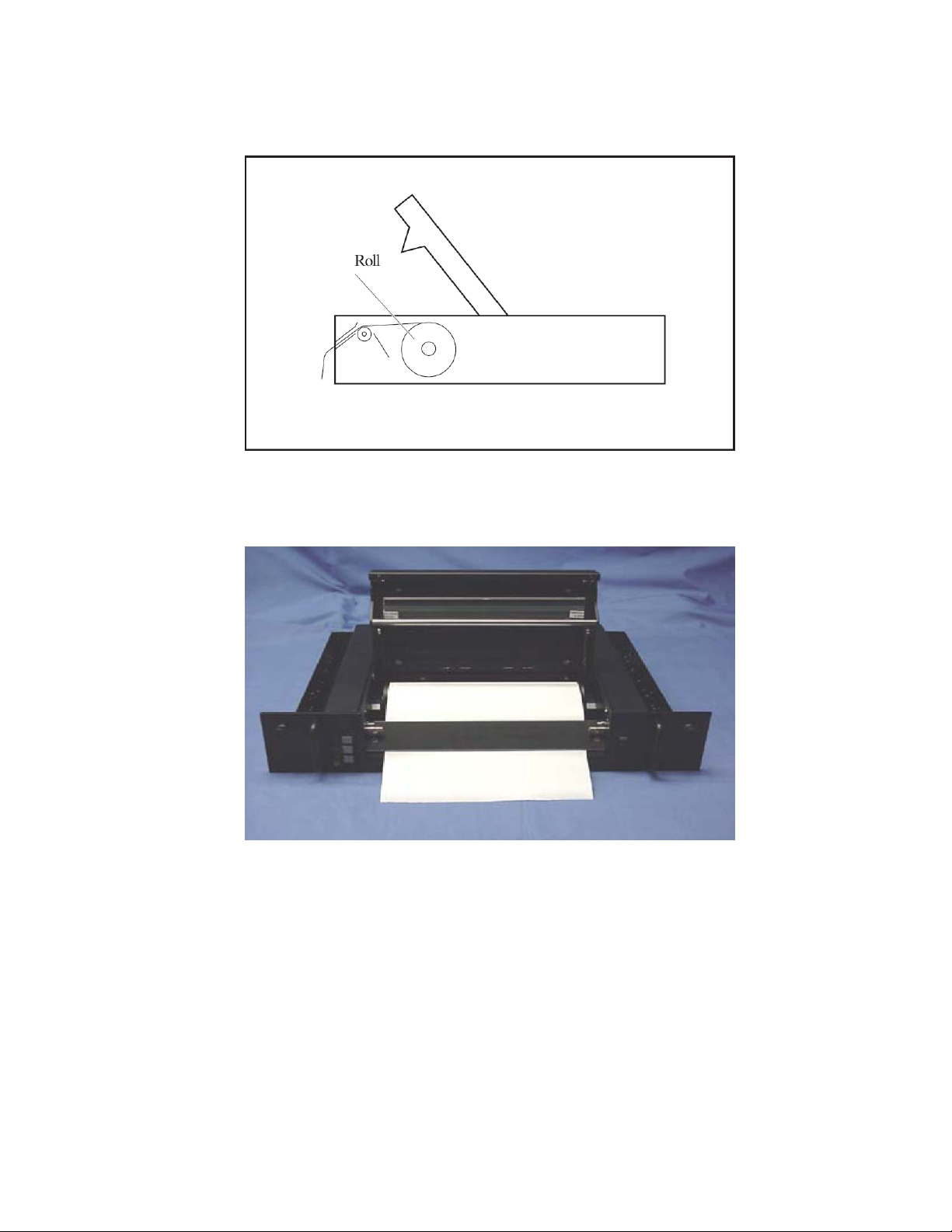
Figure 3-3 Roll paper and film path
Figure 3-4 Roll paper installed
17
Page 18
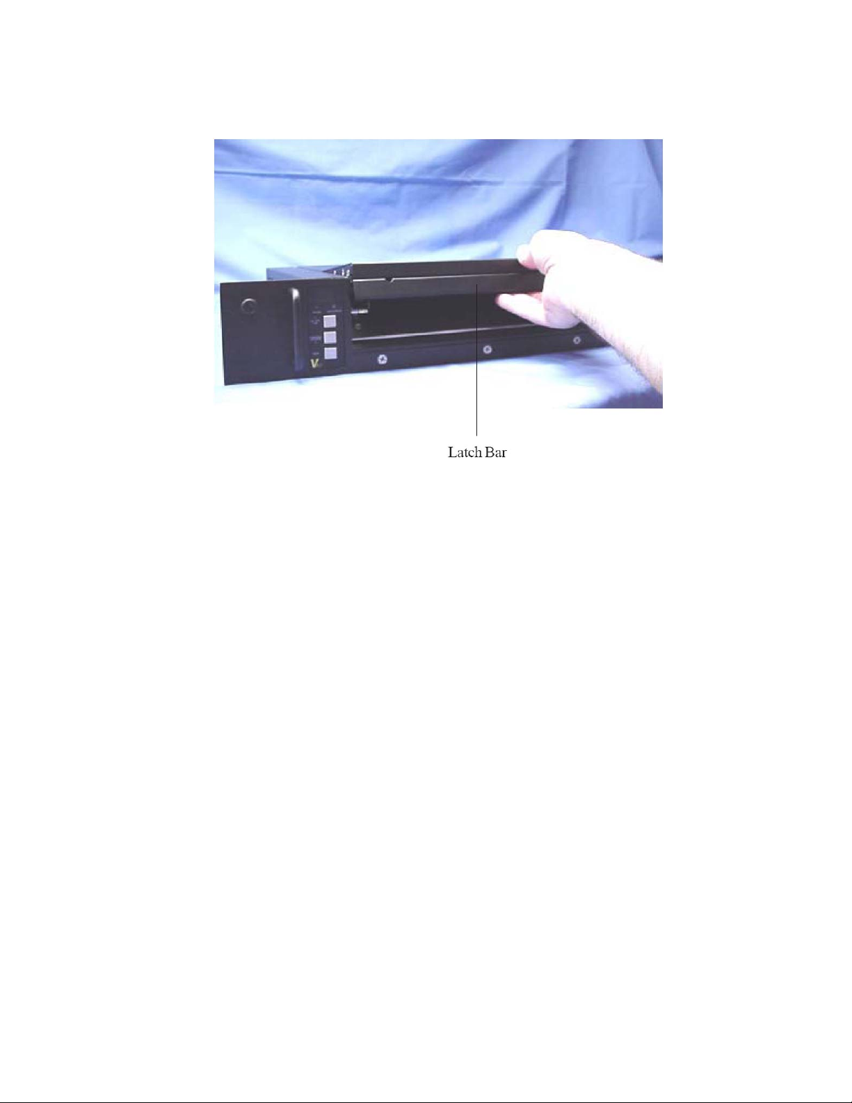
Figure 3-5 Opening the plotter Lid
Installing fan-fold paper
1. Loosen the rackmount thumbscrews and pull the plotter forward on the rails.
2. Release the lid assembly by grasping underneath the black latch bar and pulling it upwards (Figure 3-5). Op en
the plotter lid by lifting it straight upwards.
3. Remove paper roll and insert the fanfold guide over the spindle blocks (see Figure 3-6).
4. Feed the paper through the slot in the back or bottom of the plotter depending on which fan-fold paper tray is
being used.
5. If using rear load fan-fold paper, feed the media under the rear fan-fold guide bar and over the front fan-fold
guide bar. Figure 3-4. If using bottom loaded fan-fold paper, feed the media over the rear fan-fold guide bar
and over the front fan-fold guide bar.
6. Guide the paper over the blue platen roller and under the black cutter bar as shown in Figures 3-3 and 3-4.
7. When installing any media, ensure that the coated side of the media is on top and the TOF mark is on the
bottom right side.
Installing and using film
Note that the plotter operates at 1.0 inch per second when using film. Install roll film as you would paper, ensuring
that the coated side is on top.
Note that the cutter bar is designed for paper media only. Use a sharp knife or scissors to cut film media.
18
Page 19
CAUTION: Before plotting or testing on any print media, make sure that the media setting is correct. Incorrect
settings may result in damage to the printhead and warranty. The media may also be damaged.
VORSICHT: Bevor Sie mit dem Plotten oder Testdrucken auf einem Druckmedium beginnen, versichern Sie sich,
dass die Einstellungen für das Druckmedium korrekt sind. Falsche Einstellungen können zu einer Beschädigung des
Druckkopfes und zum Verlust der Garantie führen. Außerdem kann hierdurch auch das Druckmedium beschädigt
werden.
Installing rolled film
1. Loosen the rackmount thumbscrews and pull the plotter forward on the rails.
2. Release the lid assembly by grasping underneath the black latch bar and pulling it upwards (Figure 3-5). Open
the plotter lid by lifting it straight upwards.
3. Remove the fan-fold guide by grasping the two stainless steel rails and lifting it straight upwards.
4. Place the spindle hubs onto each end of the roll of film with the spacer on the left hand side spindle.
5. Orient the roll so that the film feeds off of the top of the roll.
6. Place the roll in the plotter so that the pins on the spindle hubs snap into the slots on the spindle blocks.
7. Guide the film over the blue platen roller and under the black cutter bar as shown in Figure 3-3.
Figure 3-6 Spindle blocks
19
Page 20

Figure 3- 7 Fanfold guide path
20
Page 21
4. OPERATION
4.1 POWER SUPPLY PRECAUTIONS
Turn off the power switch on the plotter before doing any of the following:
1. Unplugging the plotter
2. Cleaning the printhead
CAUTION: Take care not to discharge static into the plotter. This may
cause damage to the integrated circuits or other electronic components.
Use an approved method of static dissipation to prevent component
damage.
VORSICHT: Vermeiden Sie statische Entladung am Plotter. Dies könnte zu Sch äden an den integrierten
Schaltkreisen und anderen elektronischen Bauteilen führen. Verwenden Sie ein anerkanntes Verfahren zu
Ableitung der statischen Energie, um Geräteschäden zu vermeiden.
4.2 USING THE CONTROL PANEL
To turn the plotter on, press the main power switch at the front of the plotter. The LED display “moves in circular
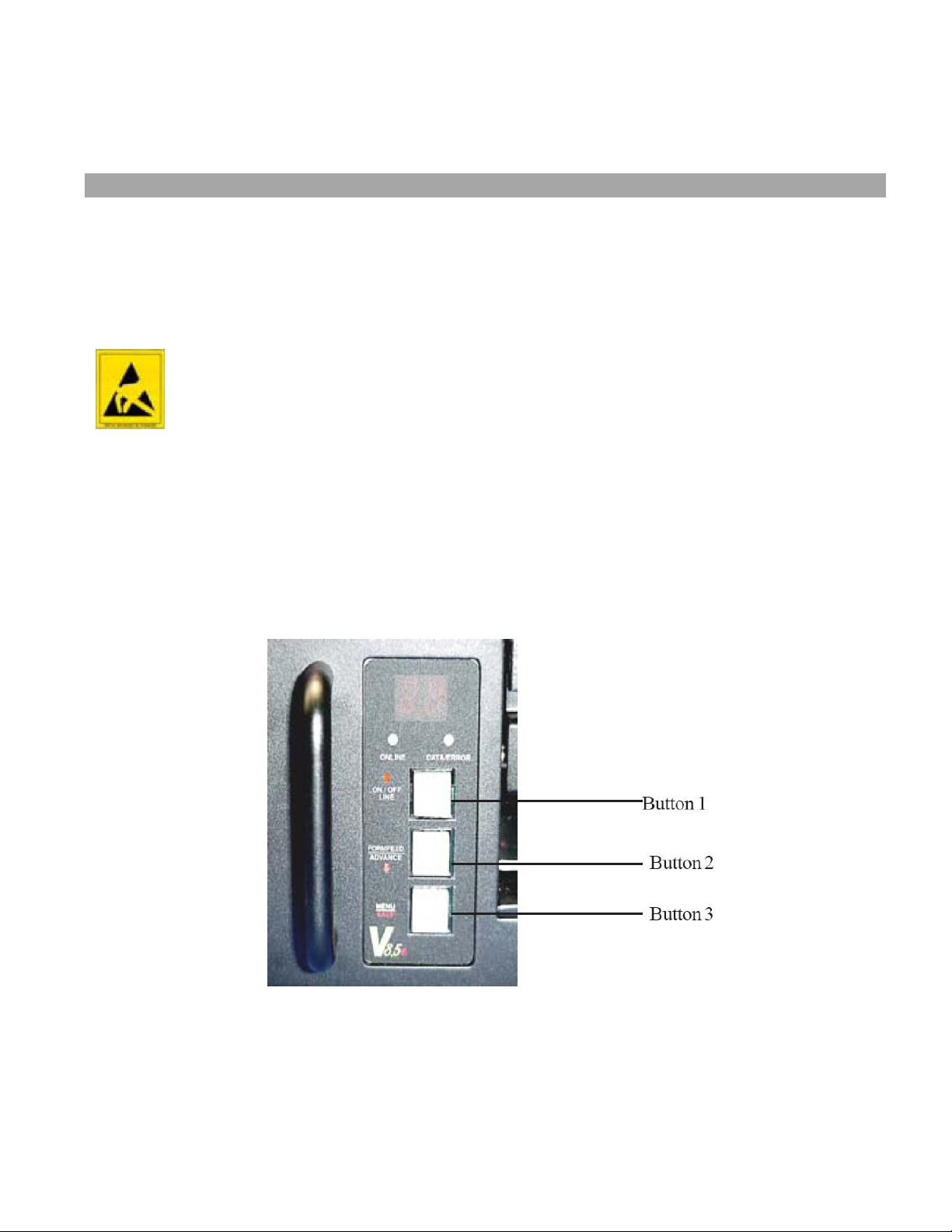
motion” during bootup, followed by the ONLINE LED illuminating. When the ONLINE LED is on, the plotter is ready
to receive data from the host. Changes to the plotter have to be made in offline mode.
Figure 4-1 Control panel
The control panel is shown in Figure 4-1. It consists of an LED display, two condition lights and three buttons.
21
Page 22

Button Function
1. UP ARROW
Online/Offline
Toggles between ONLINE and OFFLINE modes. Changes to
control panel settings can only be made in OFFLINE mode.
Selects function submenu's after menu access.
2. DOWN ARROW.
Form Feed/Advance
Works in OFFLINE mode only. Pressing and releasing causes a
form feed to the preset length. Pressing and holding
manually advances paper. Selects function sub menu's after
menu access.
3. Menu/Save
Selects function menu in OFFLINE mode by scrolling through
the list. Scrolling is from first to last only. Pressing and holding
until display flashes: saves menu settings.
Table 4-1 Control panel button functions
Table 4-1 shows the control panel button functions. The up and down arrows access function sub-menu settings
after the menu is accessed using the menu button.
Press
UP
ARROW
/FORM
FEED
to
access
Default
Value
Bytes
per
scan
Vertical
Emulation
n0
n3
P0
tP Test Plot Contrast Speed Media Scaling
(Activate
Plot test
by
pressing
MENU
button)
tP
Inactive C1 1 LP SO P3 f2 b1 t1
C8
C7
C6
C5
C4
C3
C2
4
3
2
HF
LF
HP
SE
SD
SC
Sb
SA
S9
S8
S7
S6
S5
S4
S3
S2
S1
FF
Length
PF
tF
t8
t4
g4
g3
g2
g1
b2
Grey
scale
media
Table
t2
Table 4-2 Control panel settings and organization
22
Page 23

4.3 CONTROL PANEL FUNCTIONS AND SETTINGS
See Table 4-2 for default settings and organization.
Changing function settings
For easy reference in this section, the buttons are referred to as numbers 1, 2, and 3, from top to bottom. (See
Table 4-1 for button labels and functions.)
1. Press Button 1 to turn the plotter offline. Settings can only be changed while the plotter is offline. The green
ONLINE status light turns off and the display will show: —— indicating offline status.
2. Press Button 3 to scroll through the menus.
3. For each menu item, press Button 1 or 2 (up or down arrows) until the desired setting (or sub menu item) is
shown in the display for that menu.
4. Save the setting by pressing
NOTE: Press and hold the MENU/SAVE button immediately after the desired function setting is displayed.
Advancing through the menu without doing so will not save your changes.
5. The display will then show the offline display: ——. Repeat steps 2 through 4 for each function setting.
6. Press button 1 to return to ONLINE mode. Display will be blank and online LED will be illuminated.
Default Settings
To restore the default settings of the plotter, press and hold the menu button (button 3) while powering the plotter
on. The display will briefly show “dF” during the boot up sequence, indicating that the default menu items have
been loaded.
Test plot
This function produces approximately six inches of plot in a checkerboard and dither pattern in Bimodal mode.
Generating a test plot while the plotter is set to grayscale mode will result in a grayscale plot corresponding to the
number of gray levels selected at the time. This enables the user to verify that the plotter is creating a plot image,
feeding the paper correctly, and that contrast levels and media settings are acceptable. The test plot will use the
current menu settings to generate the image.
1. Press Button 1 to put the plotter into OFFLINE mode.
2. Press Button 3 once. “tP” is displayed.
3. Press and hold Button 3 until the display flashes: The test plot will be generated.
Contrast
and holding
Button 3 (MENU/SAVE) Display shows:
23
Page 24

The contrast function adjusts the density of the output. Settings range from C 1 to C 8. Settings are relative
values: C 1 is the lightest, C 4 is normal, C 8 the darkest.
After performing a test plot or plot job, determine if the contrast is acceptable. If the output is extremely dark,
very faint, or irregular, first check that the media setting is correct (see “Media” section of this chapter).
If the contrast needs further adjusting, change the contrast setting by starting at the lowest value, adjust the
contrast upwards one value at a time, testing after each adjustment. This is particularly important when using
lightweight papers or papers with unknown specifications.
CAUTION: Thermal plotting technology involves high temperatures. Incorrect media or contrast settings can
damage the printhead or other components and void the warranty. Media damage can also occur.
VORSICHT: Bei der thermischen Plottertechnologie entstehen hohe Temperaturen. Ungeeignete Medien oder
falsche Kontrasteinstellungen können den Druckkopf oder andere Bauteile beschädigen und zu Verlust der Garantie
führen. Auch können
Beschädigungen an den Medien entstehen.
Speed
The speed function adjusts the speed of the plot output. There are four output plot speed settings in the V8.5e:
1.0, 2.0, 3.0, and 4.0 inches per second. The default setting is 1.0 inch per second which produces the highest
quality output.
If the plot speed is erratic, or if output quality is unacceptable, lowering the plot speed will result in an improved
plot quality. Such problems may arise when data enters the plotter at a slower rate than the plot speed setting.
Lowering the output plotting speed enables the plotter to match a lower input data rate and produces a smoother
output plot.
When the media setting is film (LF or HF), the plotter speed defaults to 1 inch per second. When Grayscale mode
is enabled, plot speed is dependent upon the level of grayscale selected.
Media
The media function adjusts the time that the printhead is turned on (strobe time) to create an image on the media
based upon the media type selected. The default setting is light paper. When the plotter is set to film or
grayscale mode the printhead’s requirement for strobe times is raised. This requires a slower plot speed in order to
maintain the high quality level of the V8.5e.
Note: there are two preprogrammed media tables for grayscale plotting. These calibration tables can be changed
for different medias by uploading new tables which can be provided by The Imaging Systems Group Inc. for
virtually any approved thermal media. These tables are custom tuned to provide maximum grayscale performance
on a selected media. These tables can be uploaded to the V8.5e, where they are stored in non-volatile memory
until overwritten. Tables are uploaded two at a time overwriting the factory default tables stored in T1 and T2.
CAUTION: Thermal plotting technology involves high temperatures. Incorrect media or contrast settings can
damage the printhead or other components and void the warranty. Media damage can also occur.
VORSICHT: Bei der thermischen Plottertechnologie entstehen hohe Temperaturen. Ungeeignete Medien oder
falsche Kontrasteinstellungen können den Druckkopf oder andere Bauteile beschädigen und zu Verlust der Garantie
führen. Auch können
Beschädigungen an den Medien entstehen.
24
Page 25

Scaling
The scaling function stretches or shrinks the plot over a 36-inch length of plot with settings being S0 through SE.
The default setting is (S2). To determine if scaling is needed, plot a job of a known length and measure it.
Adjustments can be made to the
scaling in increments of + or - 1/16-inch over 36 inches of plot. S0= no scale, SE = +/- 14/16” over 36 inches of
plot.
Note: Positive or negative scaling is selected through the Emulation menu setting.
Emulation (vertical resolution)
The emulation function adjusts the vertical resolution of the plot (along the media length). The settings are P0, n0,
P3, and n3. P0 and n0 are used with 200 scans/inch of plot data. The default setting (P3) is 203 scans per inch
(equal to 203 dots per inch- dpi). P3 and n3 are used for 203 scans/inch of plot data. P and n stand for Positive
and negative scaling for the scaling menu. If n is selected, the scaling factors are from no scale to -14/16” over
36” of output plot. If P is selected, the scaling factors are from no scale to +14/ 16” over 36” of plot.
Note that the horizontal resolution is determined by the printhead dot density, which is 203 dpi. The plotter can
emulate 200 dpi vertical resolution (E0 and n0 settings), to match the rastered host dat a (for Imperial units).
Form feed length
The form feed length function adjusts the distance that the media is advanced in off-line mode and when a remote
function is sent. To form feed media, put the plotter in offline mode and press the FORMFEED/ADVANCE button
without holding
Menu settings are: F2, F4, F8, tF, PF.
F2, F4, F8 cause 2”, 4”, or 8” of media to be advanced upon a formfeed. If a TOF mark is detected before the
formfeed is completed the plotter will stop upon detecting the mark, or to what the PF setting is.
tF results in the plotter advancing up to 18” while detecting for the Top of Form mark on fan fold media. The topof-form setting (tF) allows the plotter to detect top-of-form marks. These marks signal the plotter to st op the form
feed at a consistent distance from the perforated edge of the paper.
PF - Programmable advance past Top of Form- This feature allows the V8.5e to line up with the beginning of
pages when a media whose TOF marks do not meet the V8.5e specifications.
NOTE: iSys recommends only the use of approved media in the V8.5e which has been qualified to increase plotter
life and produce higher quality plots.
Once the PF feature is selected in the menu, the V8.5e will detect the media TOF mark and continue to advance
the media by the amount programmed when a formfeed or end of transmission is commanded.
.
25
Page 26

This feature is enabled by setting the formfeed menu to “PF” The advance range is from
01 hex --- 10 scans (approx 0.05”)
to
ff hex --- 2550 scans (approx 12.5”) in increments of 10 scans for each hex number.
Once the menu has been set to “PF”, the amount of advance past TOF which has been programmed into the
V8.5e will be used until it is changed. The default value is 23 Hex.
To program the amount of advance past TOF, send header:
98 XY 0A (where XY is the hex# of groups of 10 scans).
If the V8.5e accepts the setup string, the display will flash
Bytes per scan
The SCANWDTH function adjusts the scan width of the plot, defined in bytes per line. The default scan width is b1
(216 bytes per scan).
Menu settings are: b1, b2, g1, g2, g3, and g4.
b1 — 216 bytes/scan (bimodal).
b2 — 264 bytes/scan (bimodal).
g1 — 8 gray levels per scan, 1728 bytes/scan maximum.
g2 — 16 gray levels per scan, 1728 bytes/scan maximum.
g3 — 32 gray levels per scan, 1728 bytes/scan maximum.
g4 — 64 gray levels per scan, 1728 bytes/scan maximum.
Unless you are using RLTER (remote line terminate) commands, the plotter scan width must be set to the same
byte count as the rastered data from the host. Setting the scan width higher than the byte count of the raster data
does not create a wider plot. Setting the scan width incorrectly results in skewed output as the data “wraps” and
finishes the scan on the next line. This condition is identifiable on the plot in Figure 7-8.
The V8.5e contains a new method of plotting raster data. Each scan of data plotted can contain as many as 64
independent intensity levels (gray scales). The thermal print head (TPH) in the V8.5e is made up of 1728 thermal
heater nibs, and each one of these nibs can be heated to a different energy level, producing a dot on the thermal
media of varying intensity. This type of plotting can produce high-resolution images containing many shades
of gray.
Change the scan width settings by pressing the up or down arrows in the bytes/scan sub-menu.
Press and hold Button 3 until the display flashes:
26
Page 27

Grayscale media table number
t1 - media calibration table for media 1.
t2 - media calibration table for media 2.
These tables have preset values for imaging on two different medias while in grayscale mode. These medias can
be changed for different medias by uploading new tables.
Setup headers for programming the V8.5e
NOTE: The V8.5E must be in PRINT mode for the setup header string to work. Numeric values shown below are
hexadecimal, not ASCII.
NOTE: All menu functions can be remotely configured by sending a setup header string from the host to the
V8.5E through the interface. The programmable advance past TOF can be programmed in a similar
fashion.
NOTE: Sending a 00 hex in any of the setup string positions listed below allows the menu item to remain
unchanged.
The format is as follows:
Byte 1: escape code =99
Byte 2: contrast C1=11 Lightest
C2=12
C3=13
C4=14
C5=15
C6=16
C7=17
C8=18 Darkest
No Change=00
Byte 3: speed 1”=21 1.0 inches/sec
2”=22 2.0 inches/sec
3”=23 3.0 inches/sec
4”=24 4.0 inches/sec
No Change=00
Byte 4: media LP=31 Light Paper
HP=32 Heavy Paper
LF=33 Light Film
HF=34 Heavy Film
No Change=00
27
Page 28

Byte 5: scaling S0=41 No Scale
S1=42
S2=43
S3=44
S4=45
S5=46
S6=47 +/- 1/16”
S7=48 increments over 36” of
S8=49 plot up to +/- 14/16”
S9=4A
SA=4B
Sb=4C
SC=4D
Sd=4E
SE=4F
No Change=00
Byte 6: emulation P0=51 200 scans/inch vertical with positive
scaling n0=52 200 scans/inch vertical with negative
scaling P3=53 203 scans/inch vertical with positive
scaling n3=54 203 scans/inch vertical with negative
scaling No Change=00
Byte 7: formfeed F2=61
F4=62
F8=63
tF=64 Stops on TOF Mark
PF=65 Programmable advance past TOF mark
No Change=00
Byte 8: bytes/scan b1=71 (216 bytes/scan)
b2=72 (264 bytes/scan)
g1=73 8 level grayscale
g2=74 16 level grayscale
g3=75 32 level grayscale
g4=76 64 level grayscale
No Change=00
Byte 9: grayscale t1=81 (media type 1)
media table t2=82 (media type 2)
No Change=00
28
Page 29

Byte 10: line feed 0A
Example: To set the plotter to: contrast=C3
speed=1.0 ips
media=LP
scaling=S2
emulation=P3
formfeed=F2
bytes/scan=b1
grayscale media table=t1
Then send header: 99 13 21 31 43 53 61 71 81 0A
If the V8.5E accepts the setup string, the display will flash
If there are any errors in the string, such as an out of range value on one of the numbers, or any other errors in
the string format, the plotter will not accept the string, no reconfiguration will take place,and the error LED will
flash twice.
4.4 ERROR MESSAGES
1. Media Out Error: The plotter will display a small square, flashing segments and the error LED will flash. To
fix this error, reload media into the potter. Plotter must be put back online to continue plotting.
2. Hot Head Error: The plotter will display Ht and the error LED will flash. The plotter will display this error until
the thermal printhead cools to a temperature that is safe to plot again.
3. 24 Volts Error: The plotter will display 24 and the error LED will flash. If this error occurs, the 24 volt power
supply may be faulty. Please contact your product representative.
4. Thermistor Error: The plotter will display tH and the error LED will flash. If the error occurs, the thermal
printhead may be faulty. Please contact your product representative.
4.4 FEHLERMELDUNGEN
1. Medien leer: Am Plotter erscheint eine kleine quadratische blinkende Anzeige und die Fehleranzeige blinkt.
Zur Behebung dieses Fehler muss neues Aufzeichnungsmaterial geladen werden. Der Plotter muss erneut
online geschaltet werden, um den Plotting-Vorgang fortzuführen.
2. Druckkopfüberhitzung: Am Plotter erscheint Ht und die Fehleranzeige blinkt. Die Anzeige bleibt solange
bestehen, bis der Druckkopf auf eine Temperatur abgekühlt ist, bei der wieder gefahrlos geplottet werden
kann.
3. 24 Volt Fehler: Am Plotter erscheint 24 und die Fehleranzeige blinkt. Wenn dieser Fehler auftritt ist
möglicherweise die 24-VSpannungsversorgung defekt. In diesem Fall nehmen Sie mit ihrem zuständigen
Vertragspartner Kontakt auf.
4. Thermistor Fehler: Am Plotter erscheint tH und die Fehleranzeige blinkt. In diesem Fall ist möglicherweise
der thermische Druckkopf defekt. Nehmen Sie bitte mit ihrem zuständigen Vertragspartner Kontakt auf.
29
Page 30

4.5 DRIVER INSTALLATION
Driver Version 2.1 is compatible with Microsoft XP, Vista, and Windows 7: 32/64bit
Step 1
Go to Windows Start h Settings h Printers and Faxes
30
Page 31

Step 2
Select Add a Printer on the Left hand side of the window h Press Next
Step 3
Welcome to the Add Printer Wizard h Press Next
31
Page 32
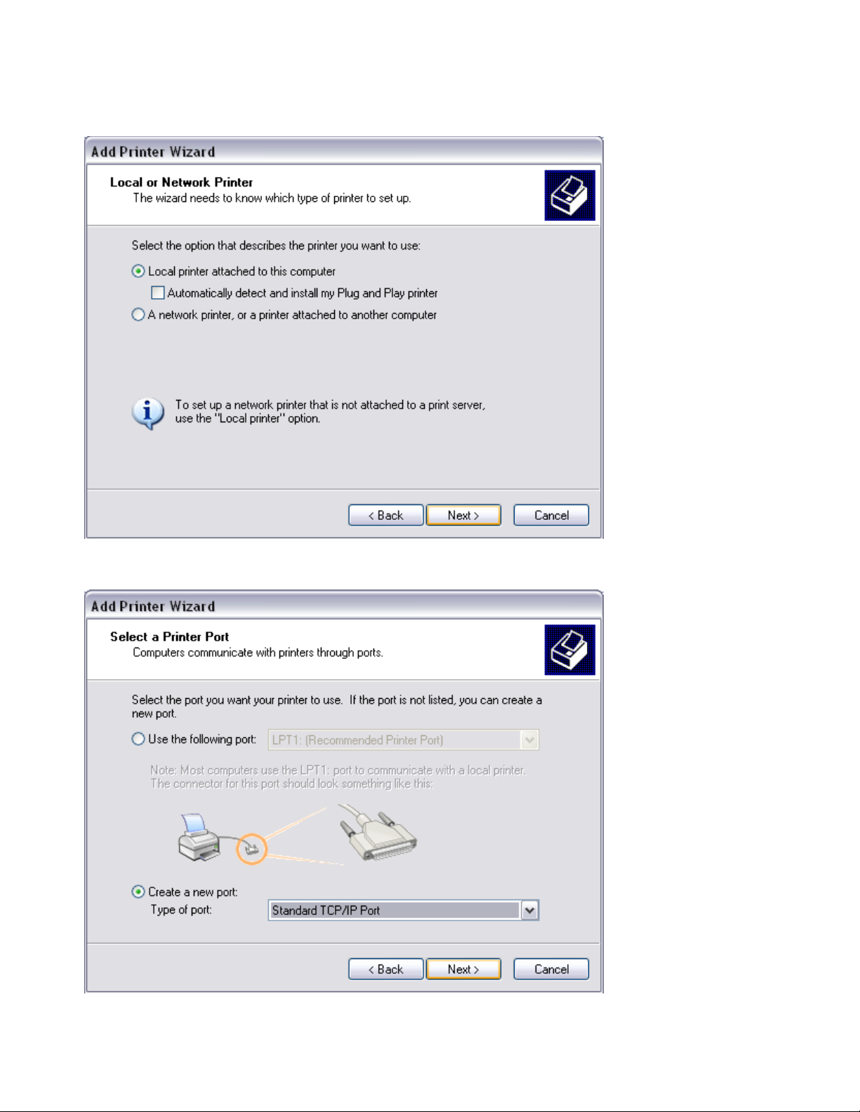
Step 4
Select Local printer attached to this computer h Press Next
Step 5
Select Create a new port: Type of port h Standard TCP/IP Port h Press Next
32
Page 33
Step 6
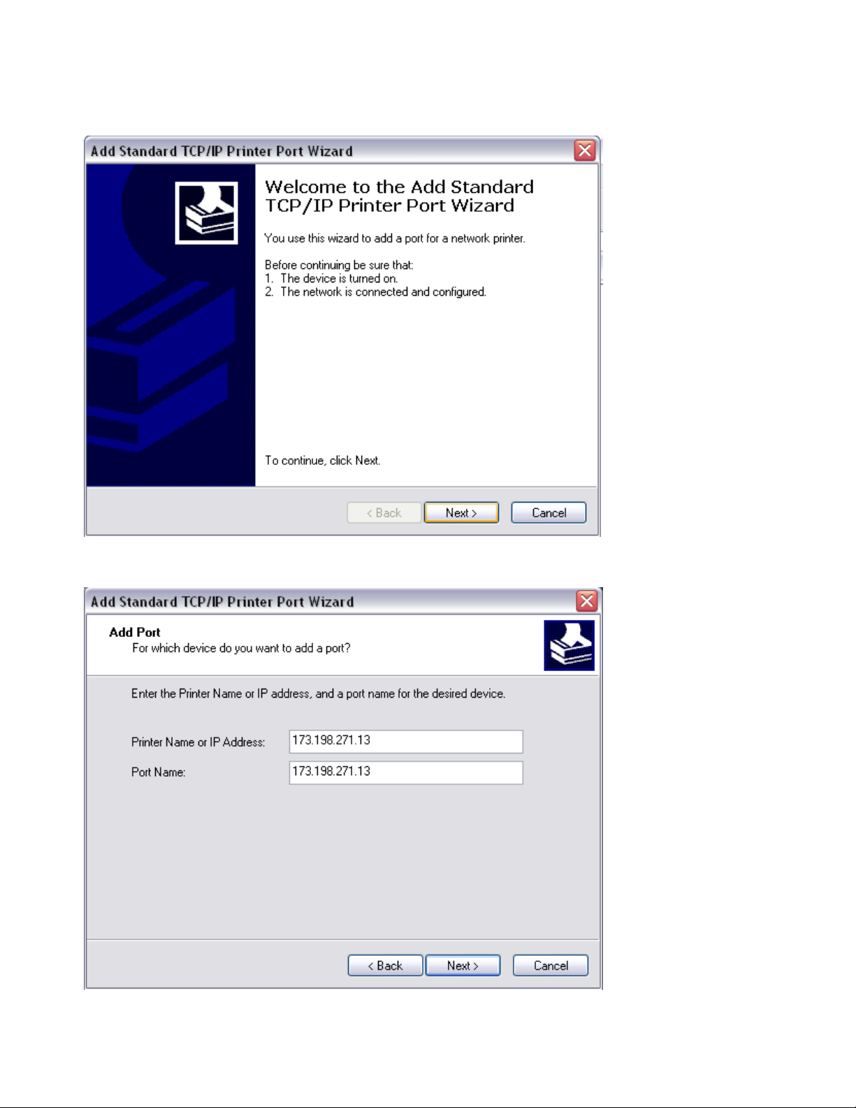
Welcome to the Add Standard TCP/IP Printer Port Wizard h Press Next
Step 7
Enter the printers IP Address into the box h Press Next
33
Page 34

Step 8
Under Device Type h Select Standard h Generic Network Card h Press Next
Step 9
Completing the Add Standard TCP/IP Printer Port Wizard h Press Finish
34
Page 35
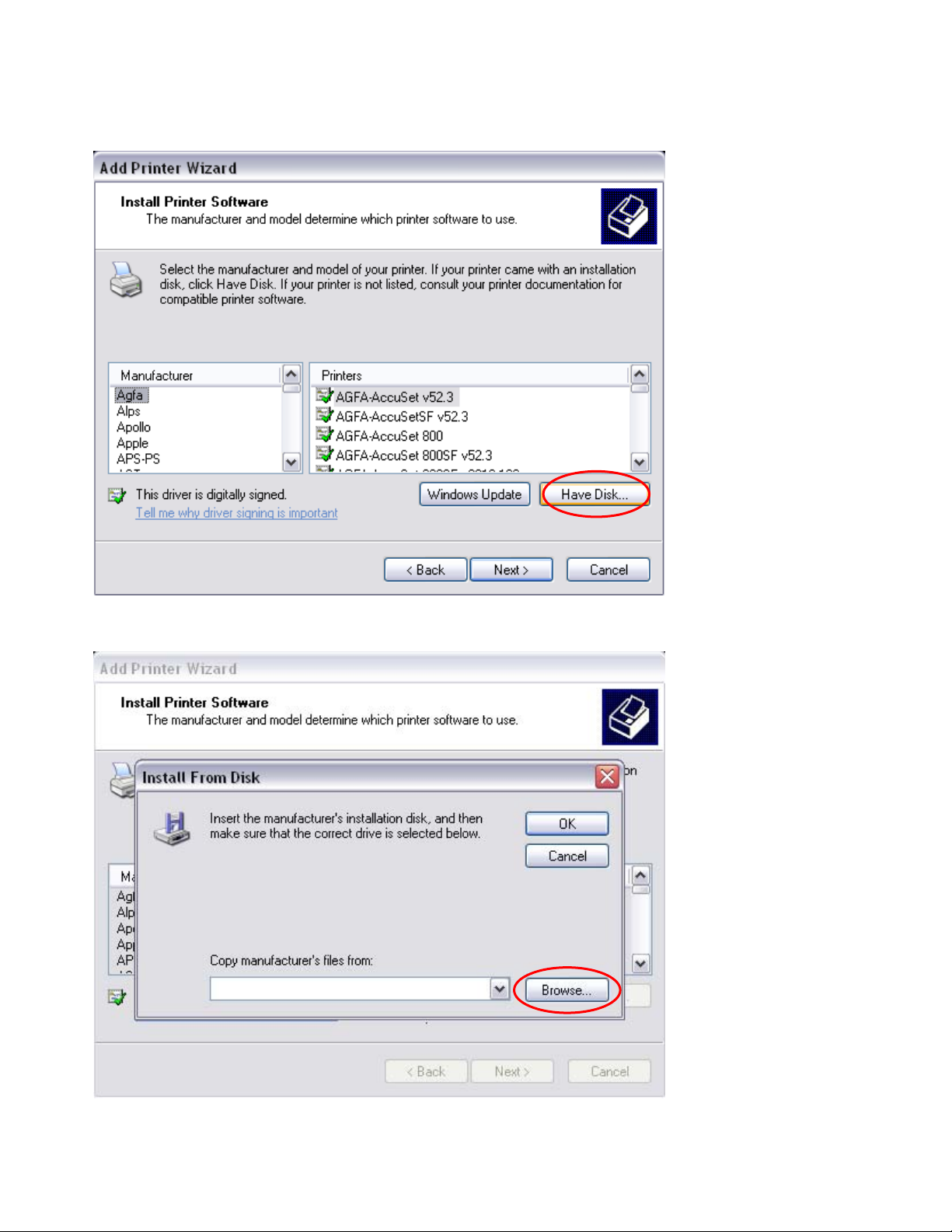
Step 10
Select Have Disk
Step 11
Select Browse h Locate and select the V8.5e Driver h Press Ok h Press Next
Step 12
35
Page 36
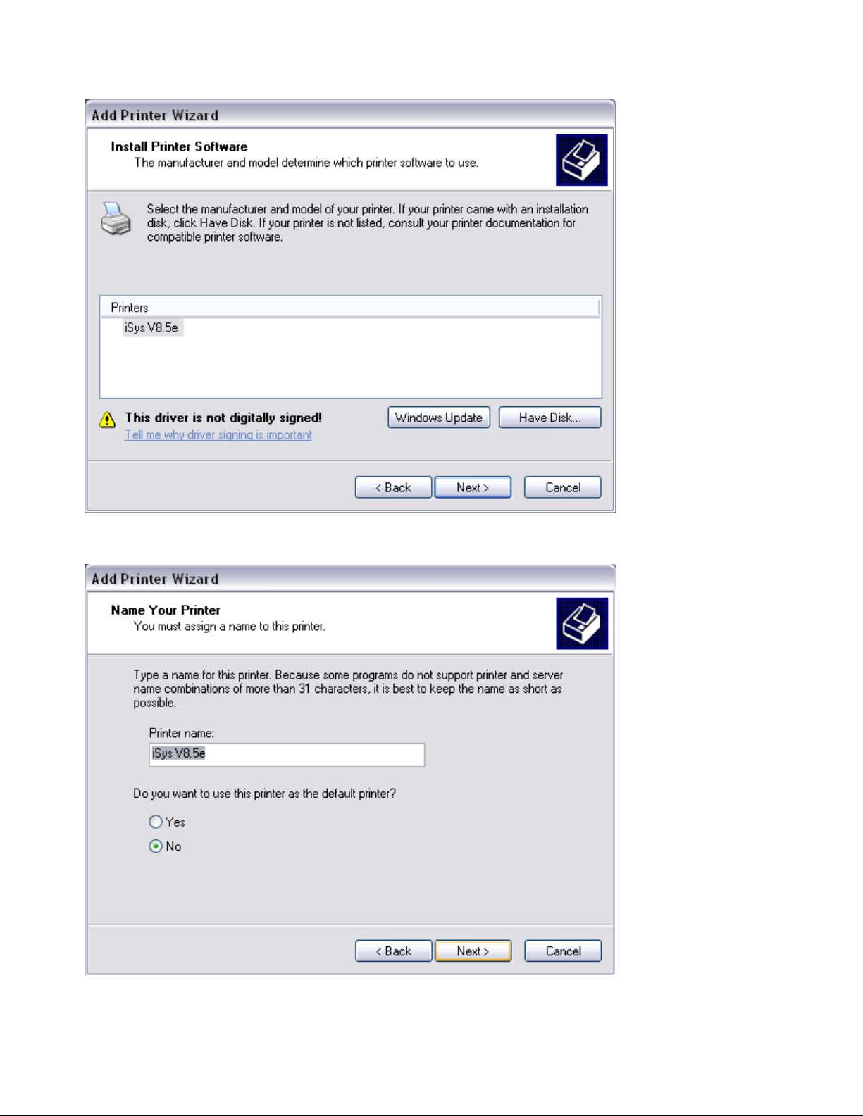
Select the iSys V12 Printer h Press Next
Step 13
Enter the printer name h Select yes if you would like the iSys V12 to be your default printer or
no if you do not h Press Next
36
Page 37
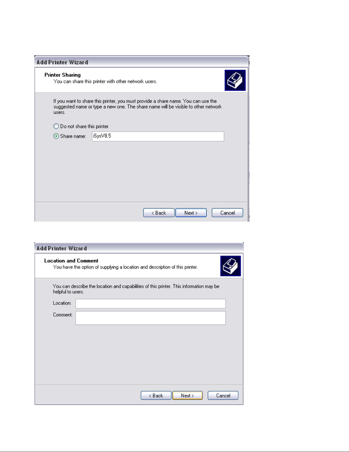
Step 14
Select a sharing option h Press Next
Step 15
Enter a location and a comment h Press Next
37
Page 38
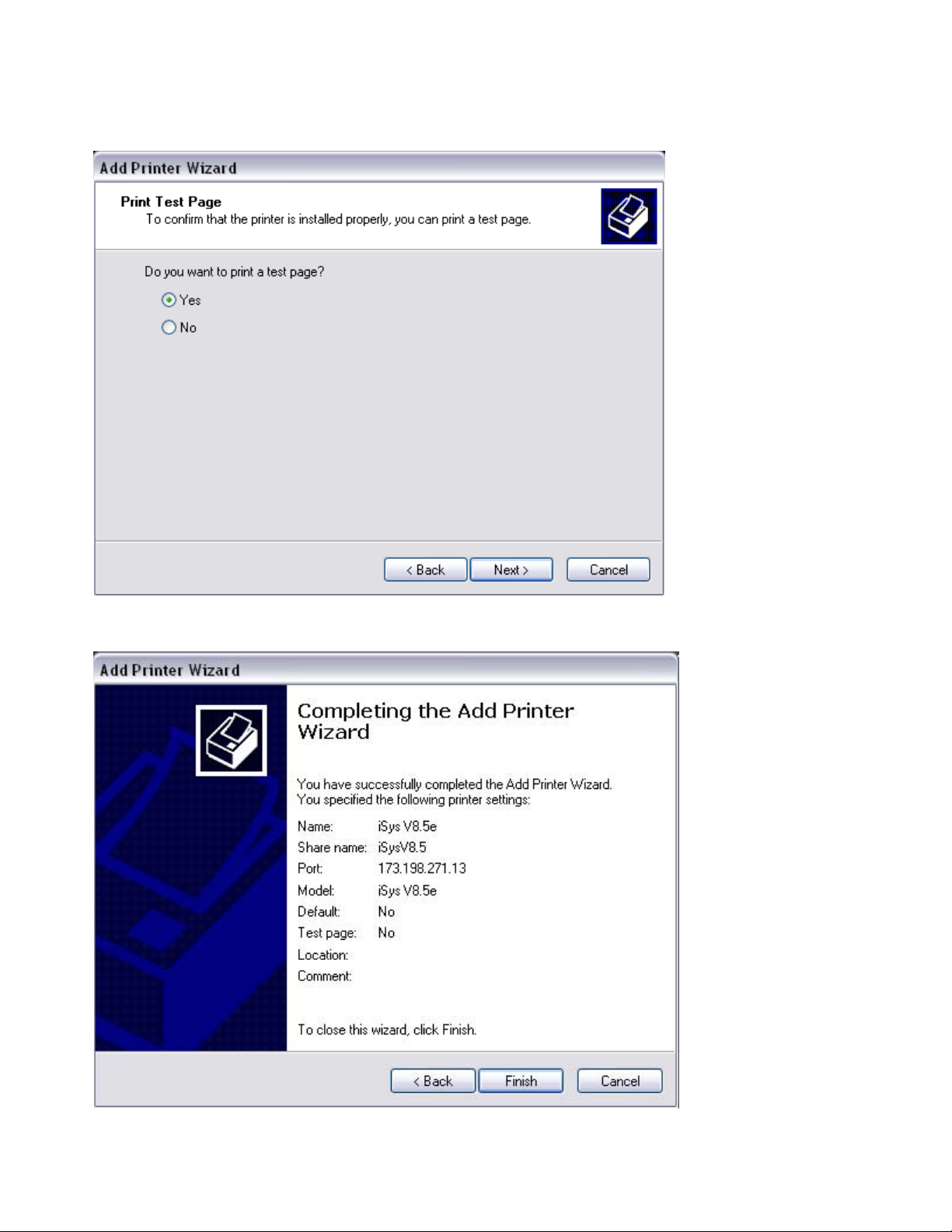
Step 16
Select Yes or No to print a test page h press Next
Step 17
Completing the Add Printer Wizard h press Finish
38
Page 39

5. THEORY OF OPERATION
5.1 INTRODUCTION
The V8.5e plotter uses thermal technology to convert data from the host computer into plotted output. Host data
enters the plotter main logic circuitry via the data port, and passes through the interface to the data buffer on the
main logic board. Control and status signals enter the main logic board at the same time as the parallel data. The
microcontroller converts the data from parallel to serial and sends the serial data to the printhead. One horizontal
line or scan, consisting of a single row of dots, is plotted. The stepper motor advances the paper for the next scan.
This cycle repeats until the plotted or printed image is finished.
5.2 PLOTTER FUNCTIONS AND FEATURES
Power supplies
The logic circuitry and printhead of the plotter are powered by a 5 Volt DC output power supply. The thermal
printhead and stepper motor are powered by a 24 Volt, 10 Amp DC power supply. Both power supplies feature an
auto-switchable input, which adapts to
different voltage or frequency inputs.
39
Page 40
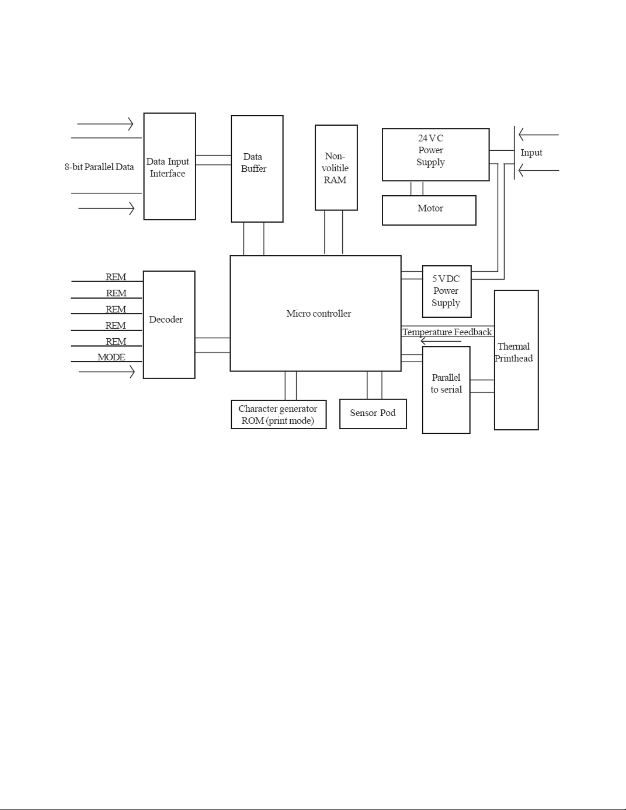
THEORY OF OPERATION
Figure 5-1 Functional block diagram
40
Page 41

Stepper motor
The V8.5e uses a bipolar, two-phase stepper motor. The motor is micro-step driven, requiring 200 full steps for
one rotation of the motor shaft. There are 32 micro-steps per full step. Thus the motor makes 6400 micro-steps for
each rotation.
5.3 INTERFACE
The data interface may be short line or, optionally, long line (see “Interface setup” in Chapter 3, Installation for
details.) The plotter is compatible with either the Versatec Greensheet or (optionally) the Centronics interface (see
Appendix A). Table 5-1 shows the active level for the plotter status signals.
Signal
Mnemonic
ONLIN Online Low Low level indicates the plotter s powered on
NOPAP No paper High Indicates there is no paper in the plotter, or
Signal
Name
Active
Level
Operation
and online
the lid is not properly closed and latched.
Table 5-1 Status Signals
Interface timing and signals
The ready signal indicates the plotter’s readiness to accept data. When READY is low, the plotter can accept one
byte of data. This byte must be accompanied by a PICLK (data strobe) pulse. Table 5-2 shows the timing
relationship for maximum data transfer.
Signal
Mnemonic
IND1 IND8
PICLK
READY
Signal
Name
Input data
Parallel input
Clock
Plotter ready
High
High
Low
Active
Level
Operation
Input lines for byte parallel data Must be
accompanied by a PICLK
Stobes a data byte present on IND1-IND8 into
the input bufffer. Minimum 300nS pulse.
Low level means plotter is ready to receive next
data byte or remote function. High level
indicates plotter is busy and will not accept data
or remote functions.
Table 5-2 Data Transfer
Note that the plotter goes busy after receiving each byte. The plotter goes busy for longer periods during the
execution of remote functions, when the input buffer is full, or when an error occurs.
41
Page 42

Table 5-3 shows the timing relationships for the remote functions. When the input buffer receives the number of
bytes necessary to plot a full scan, a write cycle is automatically initiated, causing the buffer contents to be imaged
on the medium.
Signal
Mnemonic
CLEAR Remote
RESET Remote
RLTER Remote line
RFFED Remote
REOTR Remote end
Signal
Name
clear
reset
terminate
form feed
of
transmission
Active
Level
Low Clears the input buffer.
Low Resets the plotter and re-initializes all logic
while the signal is asserted. Ready remains
high while reset is asserted.
Low Terminates the buffer data currently being
loaded, causes all previously loaded data to
be output in sequence, then outputs the
buffer data just terminated in sequence.
This command is ignored if received
immediately after a full scan has been
automatically terminated.
Low
Low Terminates the buffer data currently being
loaded, causes all previously loaded buffer
data to be output in sequence, then outputs
the buffer data just terminated in sequence.
Paper is then advanced.
Operation
Table 5-3. Remote function signals
Data rates
The plotter accommodates a wide range of data rates. The speed of the plotter can be set to 1.0, 2.0, 3.0, 4.0
inches per second. To achieve a consistent plot rate at a certain speed setting requires minimum data rates. If
data rates are inconsistent, and lower than these minimum rates, that plot speed will not be sustained. Table 5-4
shows the minimum data rates at the four speed settings.
Speed of plot Minimum data rate
1.0 inch per second 44 KB/sec
2.0 inches per second 88 KB/sec
3.0 inches per second 132 KB/sec
4.0 inches per second 176 KB/sec
Table 5-4 Minimum data rates
As with all thermal plotters, slower speeds produce the highest quality output. Plotting at a speed too high for the
data may result in the deterioration of fine details. Stops and starts caused by inconsi stent data rates may also
result in a lower quality output.
42
Page 43

Scan width
Scan width settings sent from host software can specify the number of bytes of data that will be plotted on a line.
The maximum setting that data can be rastered to is 264 bytes per scan.
NOTE: The thermal head holds a maximum of 216 bytes of data. When the plotter is set to 264 bytes per scan,
the first 216 bytes of data from the host are loaded into the thermal head to be plotted and the last 48 are
discarded.
For rastered data less than the current byte count setting on the plotter, the scan may be terminated at any byte
count by a RLTER command. If a RLTER command is asserted, the scan is terminated and the plot continues on
the next line.
Vertical resolution
The vertical resolution of the plot can be changed from the default value of 203 dpi (n3or P3) to 200 dpi (n0 or
P0, also known as Imperial unit setting). See “Emulation”, in Chapter 4, Operation, for information on control
panel settings. The plotter emulates the 200 dpi resolution by stretching the plot length. This is accomplished by
inserting micro-steps at regular intervals, so that 200 scans cover one inch of plot.
Scaling
The scaling function either stretches or shrinks the plot by removing or adding a micro-step at a set interval.
Adjustments can be made to the scaling in increments of +/- 1/16” over 36” of plot length. The interval is
determined by the scaling setting on the control panel. See “Scaling” in Operation, Chapter 4, Page 4-9, for
information on control panel settings.
Print mode
When the host asserts the PRINT mode signal, the plotter can generate ASCII characters. Table 5-5 shows the
timing relationships for print mode signals.
Signal
Mnemonic
PRINT Print Mode High Selects either print or plot
SPP Simultaneous
Signal
Name
print/plot
mode
Active
Level
mode. When signal is high,
plotter is in print mode.
Low Not used
Operation
Table 5-5. Mode signals
ASCII characters are produced as plot patterns on a 16 x 20 dot matrix through the use of a Character Generator
ROM. When one complete print line of ASCII-coded data is received, the data is converted into plot patterns. Each
character line is executed over
20 plot scans.
5.4 THERMAL PRINTHEAD
43
Page 44

The thermal printhead is comprised of a row of 1728 heater elements (nibs). Each bit within a scan addresses an
individual nib. Plot patterns are generated one scan at a time, each scan consisting of a horizontal row of dots. A
nib produces a dot if the corresponding scan bit in the buffer is a logic level “1”. Nibs in the printhead are heated,
causing a thermo-chemical reaction with the coating on the media. The intensity or period for which the nib is
heated is called the burn strobe.
Automatic Head Temperature Feedback
The thermal printhead rises in temperature as it plots images on paper, thus, less energy is required to activate
each nib as the plot proceeds to create an image of the same intensity. A thermistor embedded in the head
measures the head temperature and provides feedback information to the main logic board. The main logic board
decreases the burn strobe accordingly to keep the contrast of the plotted image consistent as the plot proceeds. If
the printhead temperature reaches 60º C, the Automatic Head Temperature Feedback circuit stops the plotter in
order to let the head cool down. The control panel display reads hot (Ht) and the error light flashes. When the
thermistor measures that the printhead temperature has cooled to 45º C, the plot resumes with no loss of data.
Film media
When the plotter is set to film mode, the strobe length is increased to accommodate the thicker media. The plot
speed is set to 1.0 inch per second to allow the longer strobe length and to maintain plot quality.
5.5 MEDIA SENSORS
The top-of-form (also known as the “I-mark”) sensor and the media sensor are contained on a media sensor
board. The top-of-form sensor consists of a focused infrared beam and
receptor that reacts to black top-of-form marks. The receptor sends a “stop form feed” command to the logic
circuitry if a mark stops the beam from reflecting back into the receptor. The paper sensor consists of an
unfocused infrared beam and receptor. If the receptor receives enough reflected light, the receptor sends no
command. If the reflected light is below the required level the receptor sends a “media out” command to the logic
circuitry and plotting stops. The “no media” indicator is displayed on the control panel.
44
Page 45

6. MAINTENANCE
6.1 MAINTENANCE
NOTE: Do not attempt to repair or modify any component of the V8.5e. If a component fails, it may be replaced
free of charge in accordance with the warranty procedures in this manual. Attempting unauthorized repairs or
modifications will void the warranty and invalidate safety approvals.
WARNING: There are voltage hazards inherent in the printhead power supply and AC input wiring. Take
reasonable precautions to avoid electrical shock. Never service any electrical component of the V8.5e while the
power cord is connected. Severe electrical shock may result.
CAUTION: Take care not to discharge static into the plotter. This may cause damage to integrated circuits or
other electronic components. Dissipate static by wearing a static disipating wrist strap, before using tools on the
plotter or touching internal components.
WICHTIGER HINWEIS: Versuchen Sie nicht, irgendwelche Bauteile des V8.5e zu reparieren oder zu
modifizieren. Falls ein Bauteil versagt, kann es gemäß den in diesem Handbuch enthaltenen Garantiebedingungen
kostenfrei ersetzt werden. Bei nicht
genehmigten Reparaturen oder Modifizierungen erlischt der Garantieanspruch und Sicherheitszertifikate werden
ungültig.
WARNUNG: Am Druckkopf und am Wechselstromanschluss bestehen gefährliche Spannungen. Lassen Sie
angemessene Vorsicht walten, um Stromschläge zu vermeiden. Ziehen Sie den Netzstecker, bevor Sie an
irgendwelchen elektrischen Bauteilen des V8.5e arbeiten. Andernfalls kann es zu erheblichen Stromschlägen
kommen.
VORSICHT: Vermeiden Sie statische Entladung am Plotter. Dies kann Schäden an den integrierten Schaltkreisen
und anderen elektronischen Bauteilen verursachen. Leiten Sie statische Elektrizität ab, indem Sie ein AntistatikArmband anlegen, bevor Sie am Plotter mit Werkzeugen hantieren oder interne Bauteile berühren.
This symbol indicates an area of possible concern due to static discharge
into the circuitry. When you see this symbol in the manual, please observe
proper static precautions to minimize damage to the circuitry.
Dieses Symbol warnt davor, dass es in diesen Bereichen möglicherweise zu statischen Entladungen an den
Schaltkreisen kommen kann. Wenn dieses Symbol im Handbuch erscheint, sind die entsprechenden
Vorsichtsmaßnahmen zu treffen, um eine Beschädigung der Schaltkreise so weit wie möglich zu vermeiden.
45
Page 46

6.2 MAINTENANCE GUIDELINES
In order to minimize the complexity of troubleshooting and repairs, the V8.5e plotter is composed, wherever
possible, of field replaceable units (FRUs). The Imaging Systems Group Inc. does not recommend troubleshooting
at a component level, but rather to the
level of these FRUs. This chapter and the troubleshooting chapter of this manual follows this approach, resulting
in faster and easier repairs. Replacing or repairing FRUs, rather than smaller components, minimizes down time and
simplifies procedures.
Use caution while troubleshooting the V8.5e. Turn the power off and unplug the power cord to prevent
electrical shock.
Seien Sie bei der Fehlerbehebung am V8.5e vorsichtig. Schalten Sie den Strom ab und ziehen Sie den
Netzstecker, um Stromschläge zuvermeiden.
6.3 REGULAR MAINTENANCE
The V8.5e thermal plotter is engineered to require minimal preventative maintenance. If the thermal printhead and
platen roller are cleaned regularly, and the plotter is kept free of debris, extra maintenance should rarely be
required.
This minimal preventative maintenance is the customers responsibility. Damage to the plotter that has in The
Imaging System Group’s opinion resulted from neglect or misuse will not be covered
under warranty.
CAUTION: No parts of the V8.5e require lubrication. All bearings are sealed and self-lubricating. These bearings
must be replaced in pairs if one fails by authorized repair depot.
VORSICHT: Kein Teil des V8.5e erfordert Schmierung. Alle Kugellager sind geschlossen und selbstschmierend.
Diese Lager dürfen nur paarweise durch eine autorisierte Servicewerkstatt ausgetauscht werden, falls eines defekt
wird.
46
Page 47

Cleaning the thermal printhead
After prolonged use, the thermal printhead picks up fibres from the media passing under it. These fine fibres
collect and compact on portions of the printhead, blocking the contact it makes with the paper during a plot and
causing faded patches. Poor contact between
the printhead and paper may also cause the affected heating elements (nibs) to fail prematurely because of
improper heat dissipation to the paper.
Clean the printhead every time you install a new roll of paper or film.
1. Turn the plotter power off.
Figure 6-1
2. Moisten (do not soak) a soft, lint-free cloth or cotton swab with 99% pure isopropyl alcohol. Rub gently along
the length of the printhead, removing any buildup of residue on the printhead.
3. Allow the alcohol to evaporate completely before using the plotter.
CAUTION: Do not touch the printhead with your fingers or other objects. Skin oil will contaminate the printhead,
which diminishes plot quality and shortens the life span of the printhead.
VORSICHT: Den Druckkopf nicht mit den Fingern oder irgendwelchen Gegenständen berühren. Fett oder Öl
verschmutzt den Druckkopf, wodurch die Druckqualität vermindert und die Lebensdauer des Druckkopfes verkürzt
wird.
47
Page 48

Cleaning the platen roller
After prolonged use, the platen roller picks up fibres from the paper passing above it. These fine fibres collect
and compact on portions of the platen roller, creating bumps. The uneven surface of the roller may cause the
printhead to contact the passing paper unevenly, producing a blotchy or faded plot.
Clean the platen roller when it appears dirty, or after approximately three rolls of paper or film have been plotted.
Lightly wipe the roller with a soft, lint-free cloth moistened in 99% pure isopropyl alcohol, turning the roller as
necessary to remove paper fragments and dust.
Replacing the fuse
The fuse is located in a clip next to the AC receptacle. Figure 3-2.
1. Unplug the power cable from the AC receptacle.
2. Insert a small screwdriver into the slot on the fuse clip to release it from the AC receptacle.
3. 3. Remove the fuse from the clip. Replace the fuse and insert the clip.
WARNING: Replace only with a fuse of identical specifications. Other fuses may cause a fire hazard. See
Chapter 2, Specifications, for fuse specifications.
WARNUNG: Beim Auswechseln der Sicherungen nur solche mit gleicher Spezifikation verwenden. Andere
Sicherungen können Brände verursachen. Siehe Kapitel 2, Spezifikationen, hinsichtlich der Spezifikation der
Sicherungen.
WARNING: Consistent damage to the plotter AC fuse indicates a serious problem and should be repaired
immediately. Contact your authorized service center.
WARNUNG: Andauernder Ausfall der Wechselstromsicherung des Plotters verweist auf ein ernstes Problem, das
sofort behoben werden sollte. Nehmen Sie Kontakt mit ihrer autorisierten Servicewerkstatt auf.
48
Page 49

7. TROUBLESHOOTING
7.1 INTRODUCTION
This chapter provides a list of problems that may be encountered with the V8.5e, and gives possible causes and
solutions for these problems.
To use this chapter, locate the problem from the list. Follow the steps in order, referring to Chapter 6,
Maintenance, where necessary.
7.2 PROBLEMS
Plotter does not plot
Possible causes: Plotter has no paper or film
Lid is not securely closed
Thermal printhead is overheated
Latch pins need adjustment
Solutions:
1. Check the media supply. Install more media if necessary as described in Chapter 3, Installation.
2. Check that the media is installed correctly and the plotter lid is securely closed. The top of the lid should be
flush with the top of the side panels.
3. If plotting has stopped in mid-task, the printhead may be overheated.
Do not intervene. The plotter will resume plotting from where it left off with no loss of data when the
printhead has cooled sufficiently.
When the printhead temperature reaches 60ºC, the plotter stops and asserts a “busy” signal to the host.
Plotting resumes when the head temperature has cooled to 45ºC. This prevents printhead damage caused by
overheating.
4. If the lid does not close securely, or if the head pressure is too low, contact your authorized service center.
49
Page 50

Plot has vertical white stripes
Figure 7-3 Plot with vertical white stripes
Possible causes: Lid is not securely closed
The printhead is dirty
Some printhead nibs are burnt out
Solutions:
1. Check that the media is installed correctly and the plotter lid is securely closed. The top of the lid should be
flush with the top of the side panels.
2. Clean the printhead as described in Chapter 6, page 6-3.
3. The thermal printhead has one or more burnt out nibs so it must be replaced. Contact your authorized service
center.
50
Page 51

Plot is blotchy or faded
Figure 7-4 Blotchy or faded plot
This problem originates from inconsistent printhead pressure across
the platen roller during plotting.
Possible causes: Lid is not securely closed
Latch pins need adjustment
Solutions:
1. Check that the media is installed correctly and the plotter lid is securely closed. The top of the lid should be
flush with the top of the side panels.
2. If the plot is fading on one side, test by pressing down on that side of the lid while the plotter is plotting. If
this helps, the latch pin needs to be adjusted on that side. Contact your authorized service center.
Plot contrast is weak
Possible causes: Lid is not securely closed
Latch pins need adjustment
Media setting is incorrect
Contrast setting is too low
24 V power supply is malfunctioning
Solutions:
1. Check that the media is installed correctly and the plotter lid is securely closed. The top of the lid should be
flush with the top of the side panels.
2. If the lid does not close securely, or if the head pressure is too low, contact your authorized service center.
3. Check that the media setting is correct. See Chapter 4, page 4-8.
4. Adjust the contrast setting as described in Chapter 4, page 4-6.
51
Page 52
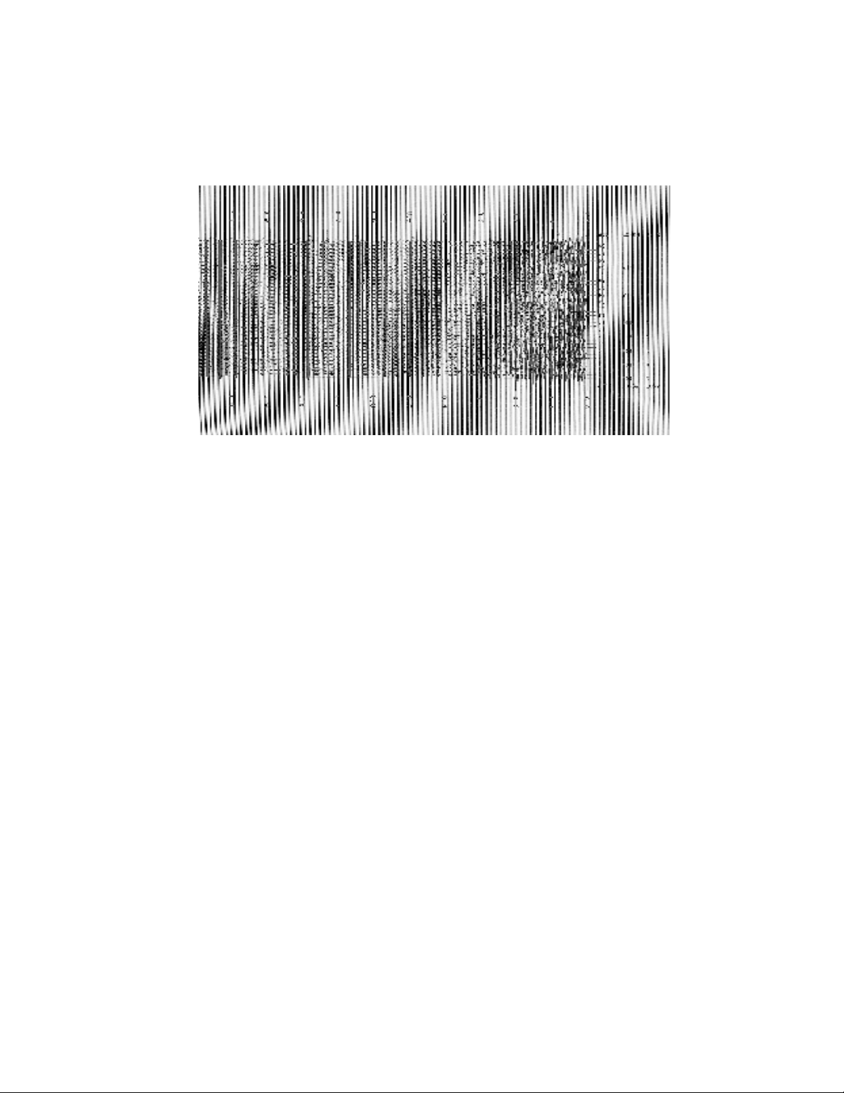
Plot has black vertical lines
Figure 7-6 Plot with black vertical lines
Possible Cause: One or more bits in each byte going to the plotter are “stuck high”.
Solution:
1. If your plotted output from the host shows these lines, run a test plot. If the lines are not present on the test
plot, the problem originates with the host data. Check the interface data cable from the host and replace it if
necessary.
Plot is wrong length
If you suspect that a plot is the wrong length, plot a job of a known length and measure it.
Possible causes: Paper is not moving freely
Scaling is incorrectly applied
Vertical emulation is incorrectly applied
Solutions:
1. Check the media feed path. Ensure that the paper is installed correctly and that the paper feed is not
obstructed.
2. Adjust or reset the scaling setting as described in Chapter 4, Operation.
3. Determine if your data requires vertical emulation and adjust the vertical resolution setting appropriately. See
“Emulation” in Chapter 4, Page 4-10.
52
Page 53

Paper is wrinkling or tearing along one edge
Possible causes: Paper feed is misaligned
Paper is incorrectly installed
Lid is not securely closed
Latch pins need adjustment
Solutions:
1. Ensure that paper is correctly aligned while feeding. If using fanfold paper, you may wish to leave the paper
in the box.
2. Check that the paper is installed correctly (see “Media Installation” in Chapter 3, Installation) and the plotter lid
is securely closed. The top of the lid should be flush with the top of the side panels.
3. If the lid does not close securely, or if the head pressure is too low, contact your authorized service center.
Plotter has no power
Possible cause: If the plotter is plugged in to a functioning outlet, then the AC fuse has blown.
Solution:
1. Replace the fuse as described in Chapter 6.
Plotter display is functioning but motor does not function
Possible cause: Either the 5 V or 24 V power supply is malfunctioning.
Solution:
1. Contact your authorized service center.
Can’t make changes to control panel settings
Possible Cause: Plotter is in ONLINE mode.
Solution:
1. Press the ON/OFFLINE button.
53
Page 54

Plot output speed is erratic
Possible Cause: Plotter speed is set too high. This is most likely to occur on the HIGH setting. Lowering the
plot speed enables the plotter to match the rate of data and produces a more steady
output.
Solution:
1. Lower the plot speed setting on the control panel as described in Chapter 4, Page 4-7.
Burning smell during plot, or “blooming” present on output
Figure 7-7 “Blooming” plot
Possible Cause: Media setting is incorrect. The thermal printhead operating temperature is too
high and is burning the media.
Solution:
1. Change the media setting on the control panel as described in Chapter 4. If unsure of the media specifications,
start at the LT PAPER setting and then increase the setting, testing plot output after each change.
CAUTION: Thermal plotting technology involves high temperatures. Incorrect media or contrast settings can
damage the printhead or other components and void the warranty. Media damage can also occur.
54
Page 55
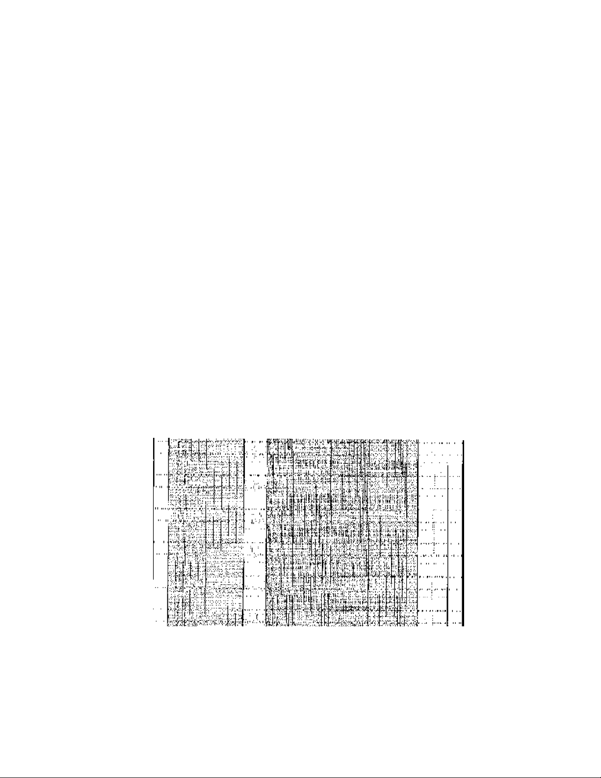
VORSICHT: Bei der thermischen Plottertechnologie entstehen hohe Temperaturen. Ungeeignete Medien oder
falsche Kontrasteinstellungen können den Druckkopf oder andere Bauteile beschädigen und zu Verlust der Garantie
führen. Auch können
Beschädigungen an den Medien entstehen.
Form feed stops before desired length
Possible Cause: The form feed length is too short. The form feed stops before the paper sensor
can read the “top of form” mark.
Solution:
1. Adjust the FFLENGTH setting on the control panel as described in Chapter 4, Page 4-10.
Form feed does not stop at top-of-form marks
Possible Cause: The top-of-form sensor is not reading the marks.
Solution:
1. Contact your authorized service center.
Plot is skewed or unreadable
Figure 7-8 Skewed plot
Possible Cause: The scan width is incorrect.
Solution:
1. Adjust the scan width (byte count) in your host software to 216 bytes or less.
55
Page 56

8.0 WARRANTY
The Imaging Systems Group Inc. (iSys) warrants our V8.5e plotters to be free from defects in materials and
workmanship as follows:
Labour and parts are warranted for a period of four (4) years from the date of purchase.
This warranty applies only to products purchased from an authorized dealer or agent, and extends only to the
original Retailer purchaser.
This warranty only covers defects arising under normal usage within the duty cycles per specifications, and
does not cover malfunction or failures resulting from misuse, abuse or neglect.
Consumable accessories are not included in this warranty.
56
Page 57
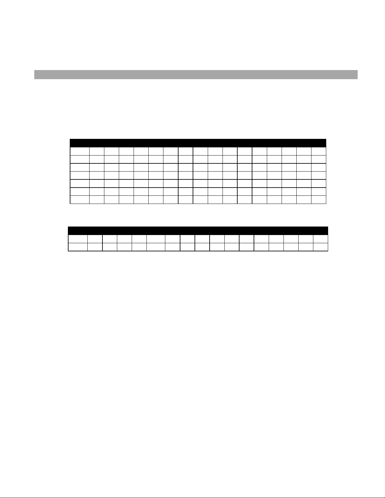
A. APPENDIX
ASCII TABLES
MSN: Most significant nibble
LSN: Least significant nibble
MSN 0 1 2 3 4 5 6 7 8 9 A B C D E F
2 ! “ # $ % & ‘ ( ) * + , - . /
3 0 1 2 3 4 5 6 7 8 9 : ; < = > ?
4 @ A B C D E F G H I J K L M N O
5 P Q R S T U V W X Y Z [ \ ] ^ 6 ‘ a b c d e f g h i j k l m n o
7 p q r s t u v w x y z { l } ~ Ŝ
Table A-1 Normal ASCII character set
MSN 0 1 2 3 4 5 6 7 8 9 A B C D E F
0 EOT LF FF CR
Table A-2 ASCII control code character set
LSN
LSN
57
Page 58

B. APPENDIX
INTERFACE CONNECTOR PIN ASSIGNMENT
Signal Pin Return Pin Signal Name Mnemonic
1 20 Input Bit 1 (LSB) INDI 1
2 21 Input Bit 2 INDI 2
3 22 Input Bit 3 INDI 3
4 23 Input Bit 4 INDI 4
5 24 Input Bit 5 INDI 5
6 25 Input Bit 6 INDI 6
7 26 Input Bit 7 INDI 7
8 27 Input Bit 8 (MSB) INDI 8
9 28 Clear CLEAR
10 29 Parallel Input Clock PICLK
11 30 Ready READY
12 31 Print PRINT
13 Not Connected NC
14 33 Simultaneous Plot / Print SPP
15 34 Remote Reset RESET
16 35 Remote Form Feed RFFED
17 36 Remote End of Transit REOTR
18 37 Remote Line Terminate RLTER
19 37 No Paper NOPAP
32 37 Online ONLIN
Table B-1. Versatec cable pin outs (straight through)
Pin Signal Pin Signal
1 STROBE 14 AFXT
2 DATA 0 15 ERROR
3 DATA 1 16 RESET
4 DATA 2 17 SLCTIN
5 DATA 3 18 GND
6 DATA 4 19 GND
7 DATA 5 20 GND
8 DATA 6 21 GND
9 DATA 7 22 GND
10 ACK 23 GND
11 BUSY 24 GND
12 PE 25 GND
13 SLCTOUT
Table B-2. Centronics cable pin outs (straight through)
58
Page 59

C. APPENDIX
CENTRONICS INTERFACE BOARD
The new Centronics adapter (rev1-2) implements some improvements over the previous (rev1-1) adapter card.
These include:
a. Rev 1-2 cards will accept either of the two data transfer methods described below automatically; no
switches or jumpers required.
b. Reliable data transfers using up to 40 ft length of shielded cable.
c. Rev 1-1 adapter cards exhibit inconsistent data transfer with newer generation PC.’s equipped with high
speed integrated Centronics parallel ports.
The following are two transfer formats that can be used with the optional V8.5E Centronics parallel adapter:
1) Standard transfer format
To place the V8.5E Centronics adapter in raster mode, the following 3 bytes (hex) must be sent to the
Centronics adapter card:
Once these 3 bytes are sent, rastered plot data can be sent to the plotter as follows:
V8.5E bytes/scan menu setting bytes/scan raster data
Once the V8.5E Centronics adapter is set to raster mode it will remain in raster mode until the init line of the
host Centronics port is pulsed or the plotter power is cycled. This will return the adapter to print mode.
2) Enhanced transfer format
For more flexibility, a 6 byte header can be sent before each scan of rastered data. This header allows
variable bytes/scan plotting. The Centronics adapter also returns to print mode at the end of every scan
using this transfer method. This allows the five 1B, 4X commands or the standard ASCII control codes listed
below in section 3 to be used during plotting. The format of the 6 byte header is:
1B 2A 72 XX YY 01 where XX = high byte of the
1B, 2A, 00
b1 216
b2 264
g1-g4 1728
number of bytes/scan
YY = low byte of the
number of bytes/scan
59
Page 60

Example: To send a plot that is rastered to 200 bytes/scan, send the following 6 byte header before each
and every scan of 200 bytes:
1B 2A 72 00 C8 01 00C8 hex = 200 decimal
for a plot consisting of 1728 bytes/scan, send
1B 2A 72 06 C0 01 06C0 hex = 1728 decimal
The valid number of bytes that can be sent to the V8.5E using this transfer method is as follows:
V8.5E bytes/scan menu setting valid number of bytes/scan raster data (XX YY)
Specifying XX YY at values greater than those indicated will cause the V8.5E to terminate scans incorrectly.
3) 1B 4X and control characters
Other commands that can be sent to the V8.5E Centronics adapter:
1B 41 remote clear
1B 42 remote line terminate
1B 43 remote end of transmission
1B 44 remote form feed
1B 45 remote reset
1B 50 ZZ sends blank scans to plotter from ZZ = 01 hex to FF hex
NOTE: These commands must be sent when the plotter is in print mode. The commands will be ignored and
interpreted as raster data if they are sent at any other time.
The V8.5E plotter also obeys standard control characters which must be sent when the plotter is in print
mode:
04 end of transmission
0A line feed
0C form feed
NOTE: Print mode on the V8.5E means that all bytes that are received by the plotter are interpreted as ASCII
characters and printed at 108 characters/line.
60
 Loading...