

Page 1
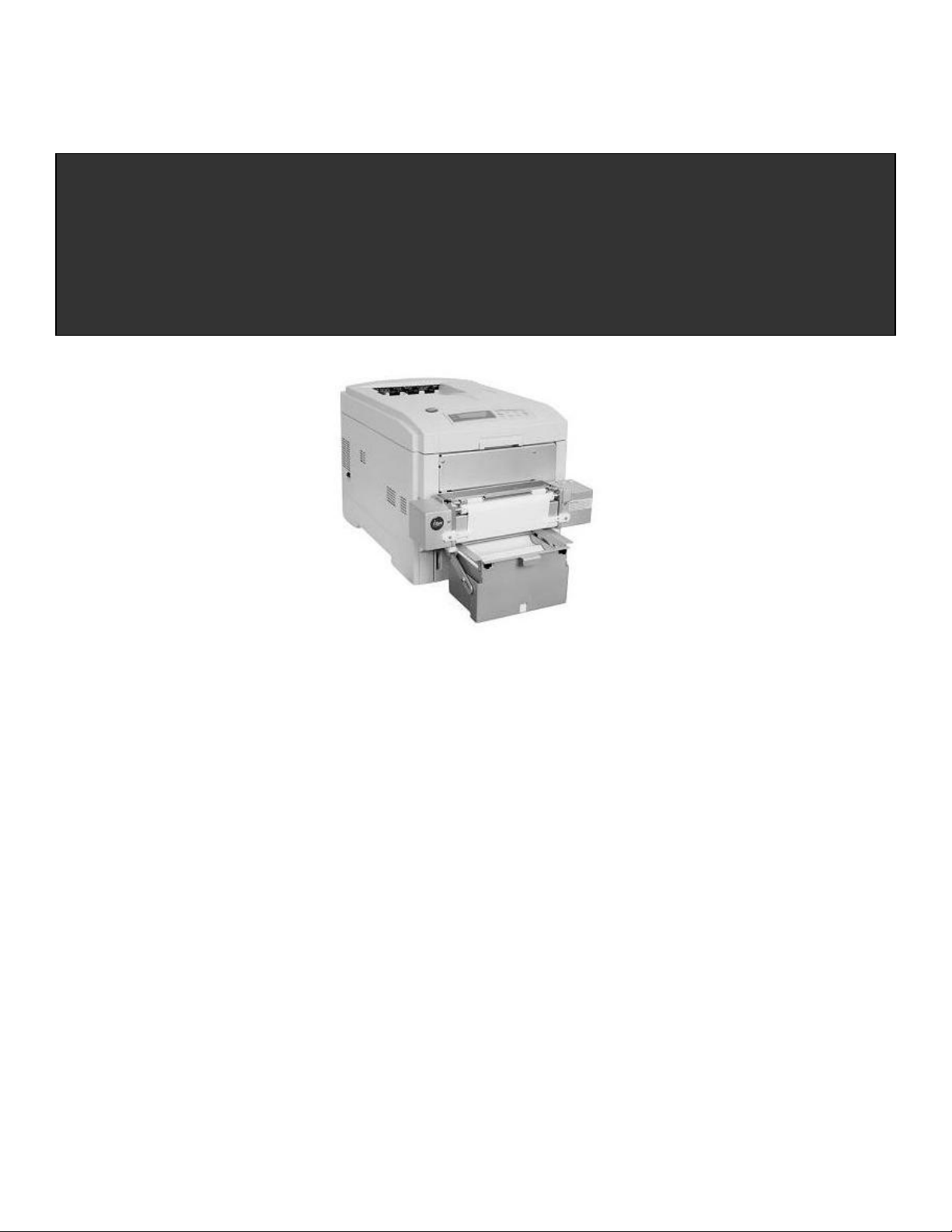
iTerra Elite
Quick Start Guide
iSys-The Imaging Systems Group Inc.
iTerra Elite Quick Start Guide © iSys-The Imaging Systems Group Inc. Rev1.2-030708
Page 2

TABLE OF CONTENTS
1. INSTALLATION
I. INSTALLING CONSUMABLES AND PRINT MEDIA ................................................... 4
II. INSTALLING ACCESSORIES ................................................................................... 11
III. CONNECT TO POWER ........................................................................................... 16
IV. LOADING CONTINUOUS FORM FEED PRINT MEDIA ......................................... 17
V. PRINT MEDIA PROPERTIES ................................................................................... 21
2. ORDERING CONSUMABLE SUPPLIES
I. HOW TO ORDER QUALIFIED MEDIA AND CONSUMABLES ................................. 22
3. INTERFACE SETUP AND INSTALLATION
I. INTERFACES ............................................................................................................. 23
II. LOCAL INSTALLATION ............................................................................................ 24
III. NETWORK INSTALLATION ..................................................................................... 25
IV. PRINT DRIVER INSTALLATION ............................................................................. 26
V. NETWORK CARD IP ADDRESS-CHECKING AND SETTING ................................ 37
VI. WEB BROWSER TO PRINTER (Advanced Users and Administrators) ................. 38
VII. WINDOWS 2000 & XP PRINT DRIVER PROPERTIES ......................................... 39
VIII. GENERAL TAB ...................................................................................................... 39
VIX. SHARING TAB ....................................................................................................... 40
X. PORTS TAB .............................................................................................................. 40
XI. ADVANCED TAB ..................................................................................................... 41
XII. COLOR MANAGEMENT TAB ................................................................................. 41
XIII. SECURITY TAB ..................................................................................................... 42
XIV. DEVICE OPTION TAB ........................................................................................... 42
4. OPERATION – CONTINUOUS PAPER MODE
I. PRINTER CONTROL PANEL OVERVIEW ................................................................ 43
II. FEEDER OPERATING INSTRUCTIONS .................................................................. 45
_________________________________________________________________________________________________________________________
PAGE 2 --- iTerra Elite Quick Start Guide © 2008 iSys-The Imaging Systems Group Inc.
Page 3

III. EXIT SPEEDS AND PRINT CONTROLS ................................................................. 47
IV. OUTPUT VIA BACK ................................................................................................. 50
V. OUTPUT VIA TOP (Using optional top stacker) ....................................................... 51
VI. OUTPUT PROBLEMS .............................................................................................. 53
5. PRINT DRIVER PREFERENCES
I. CHANGING THE iSys CLP825 PRINTING PREFERENCES .................................... 56
II. THE SET UP TAB ...................................................................................................... 57
III. THE JOB OPTIONS TAB ......................................................................................... 65
IV. COLOR TAB ............................................................................................................. 80
V. COLOUR MATCHING ............................................................................................... 82
6. TROUBLESHOOTING
I. ERROR CODES ......................................................................................................... 86
II. CONTROL PANEL MESSAGES ............................................................................... 94
III. PAPER JAMS ........................................................................................................... 97
7. FAQs AND SOLUTIONS FOR COMMON PROBLEMS
I. PAPER FEED PROBLEMS ...................................................................................... 103
II. PROBLEMS PRINTING FROM WINDOWS ............................................................ 104
III. PROBLEMS WITH POOR QUALITY PRINTING ................................................... 108
8. QAN MANAGEMENT
QAN MANAGEMENT PROGRAM .............................................................................. 116
9. JOB MANAGEMENT
JOB MANAGEMENT ................................................................................................... 118
10. SERVICE AND SUPPORT
SERVICE AND SUPPORT .......................................................................................... 119
_________________________________________________________________________________________________________________________
PAGE 3 --- iTerra Elite Quick Start Guide © 2008 iSys-The Imaging Systems Group Inc.
Page 4
1. INSTALLATION
Follow the steps below to properly install the printer consumables and accessories.
I. INSTALLING CONSUMABLES AND PRINT MEDIA
Removing Protective Shipping Materials
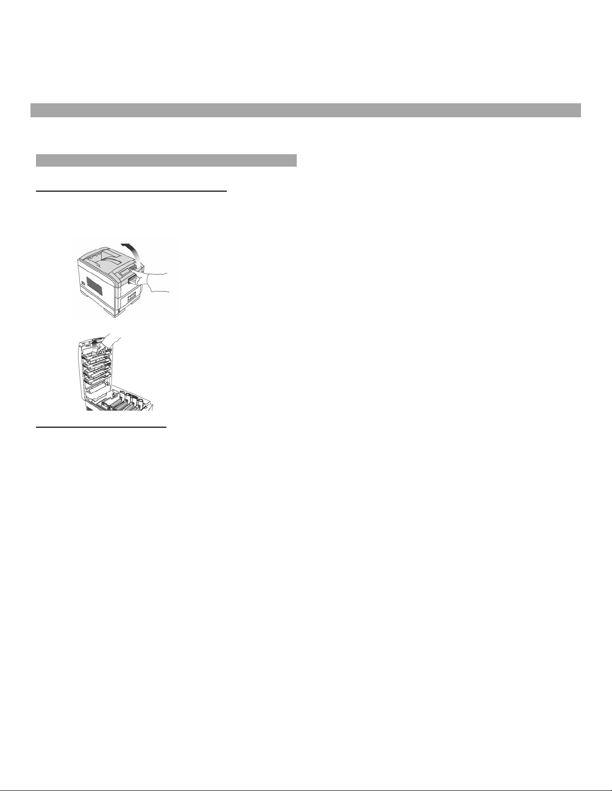
1) Remove the two strips of shipping tape from the rear door paper exit.
2) Pull up the release latch and open the cover.
3) Remove the cardboard v-shaped shipping restraint from behind the LED heads.
Preparing the Image Drums
_________________________________________________________________________________________________________________________
PAGE 4 --- iTerra Elite Quick Start Guide © 2008 iSys-The Imaging Systems Group Inc.
Page 5
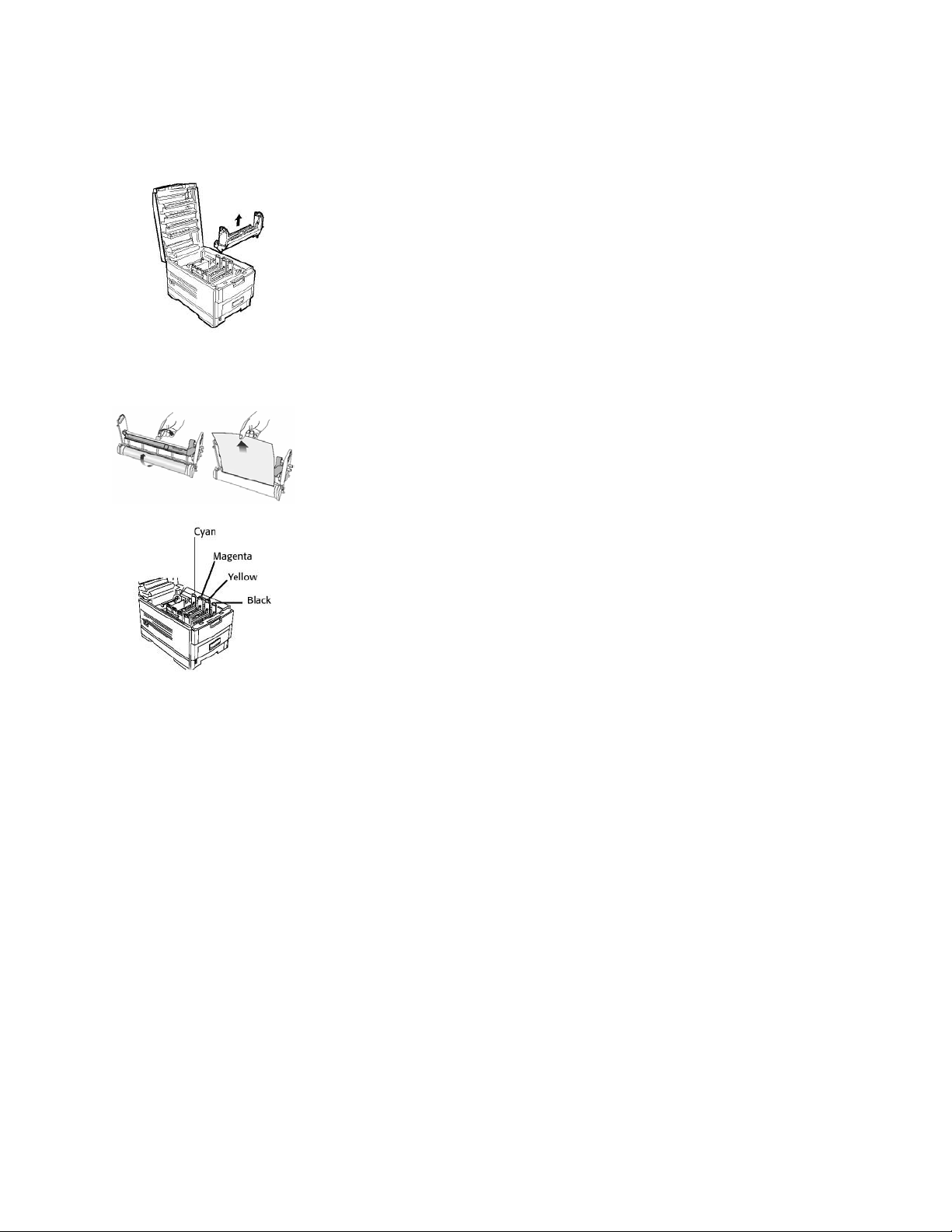
1) Lift out the four image drums and place them on a flat surface.
2) Remove the protective sheet. Push the tab in the direction of the arrow and remove the orange blanking plate
from each drum.
3) Place the drums back into the printer.
_________________________________________________________________________________________________________________________
PAGE 5 --- iTerra Elite Quick Start Guide © 2008 iSys-The Imaging Systems Group Inc.
Page 6

4) If it is ever necessary to remove the entire drum tray, simply do so by holding the blue handles on either side of
the tray and pull upwards.
CAUTION:
Ensure the drums are in their correct color position.
_________________________________________________________________________________________________________________________
PAGE 6 --- iTerra Elite Quick Start Guide © 2008 iSys-The Imaging Systems Group Inc.
Page 7
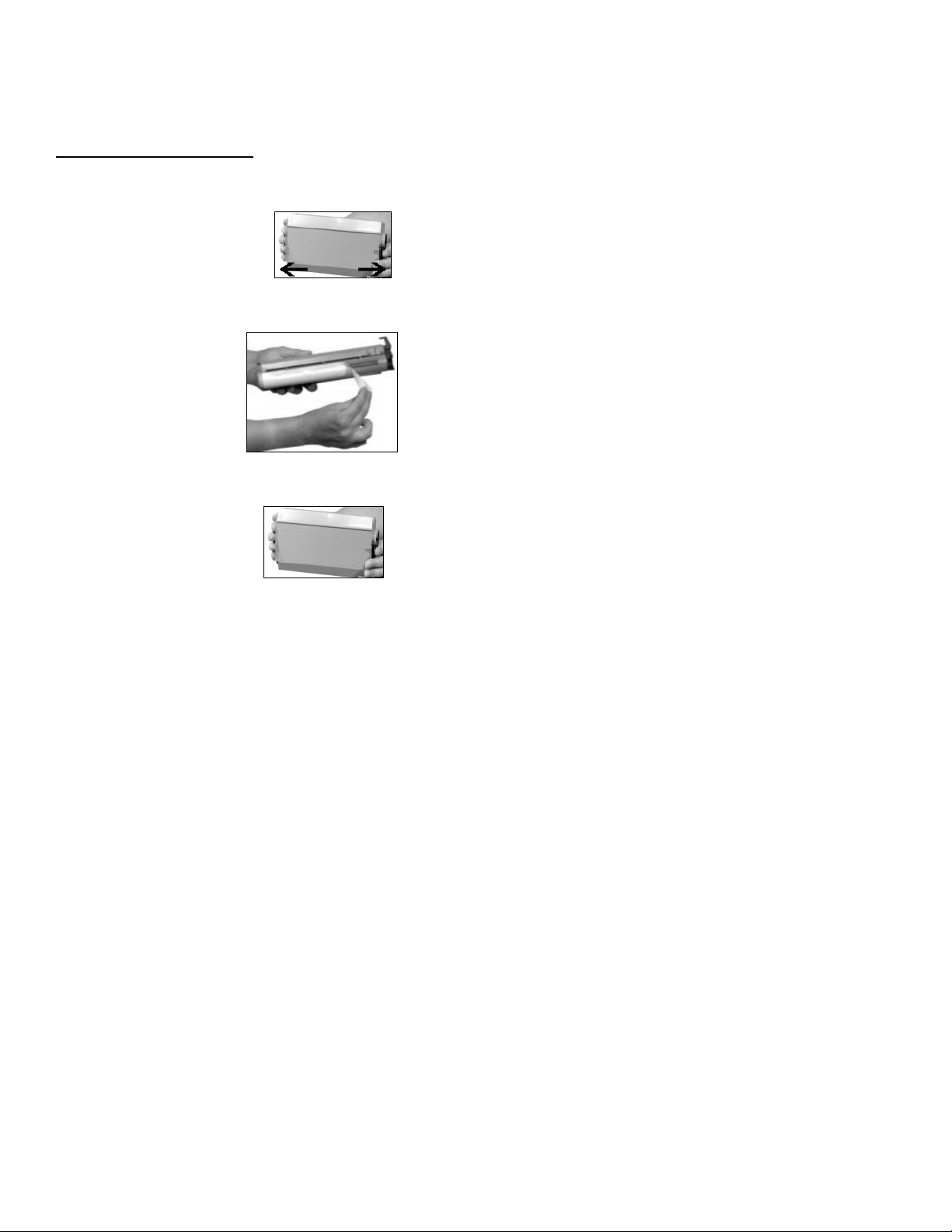
Installing Toner Cartridges
1) Remove plastic bag from black toner cartridge and lightly shake it back and forth to loosen settled toner.
2) Hold the cartridge in a horizontal position and remove protective tape.
3) Hold the cartridge in the vertical position, with the port on the left and the blue lock lever on the right.
4) Lower the left end of the cartridge into the image drum, closest to the front of the printer and matched to the black
drum, so that the tube on the drum slides into the port on the toner cartridge.
_________________________________________________________________________________________________________________________
PAGE 7 --- iTerra Elite Quick Start Guide © 2008 iSys-The Imaging Systems Group Inc.
Page 8

5) Press the cartridge toward the left slightly, and then lower the right end, aligning the white tab with the groove in
the drum.
6) Push the lock lever toward the back of the printer until it stops.
NOTE:
After installing a new toner cartridge, the message TONER LOW or CHANGE TONER may appear on the
display after the printer is turned on. If this message does not disappear after a few pages have been
printed, reinstall the appropriate toner cartridge.
_________________________________________________________________________________________________________________________
PAGE 8 --- iTerra Elite Quick Start Guide © 2008 iSys-The Imaging Systems Group Inc.
Page 9

CAUTION:
Repeat the process for each toner cartridge, being careful to match the toner color to the drum.
7) Close the cover.
_________________________________________________________________________________________________________________________
PAGE 9 --- iTerra Elite Quick Start Guide © 2008 iSys-The Imaging Systems Group Inc.
Page 10
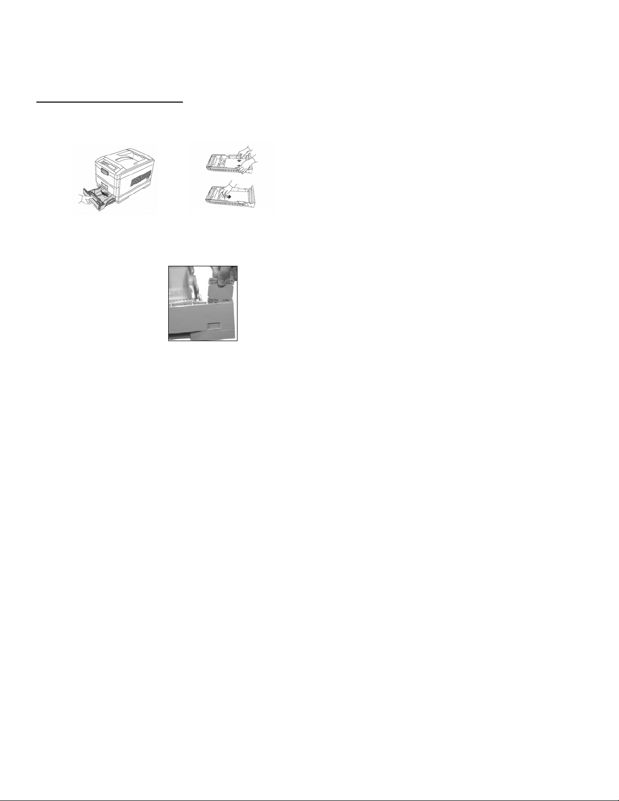
Loading Cut Sheet Print Media
1) Pull the paper tray out of the printer and adjust the paper guides and rear paper stopper for the paper size you are
using (see iTerra Elite Print Media Specifications).
2) Fan the paper (max. 530 sheets 20-lb. paper) and load it. Keep it below the “MAX” mark.
3) If necessary, lift out the paper media indicator and reinsert it with the proper paper size showing.
4) Push the tray back in. The paper gauge indicates the amount of paper inserted or remaining in the tray.
_________________________________________________________________________________________________________________________
PAGE 10 --- iTerra Elite Quick Start Guide © 2008 iSys-The Imaging Systems Group Inc.
Page 11
II. INSTALLING ACCESSORIES
The items you will need to install your accessories are as follows: feeder, feeder-to-printer cable, media input tray, and top
media stacker (optional).
WARNING:
The iTerra Elite printer is very heavy and requires two people when lifting or moving.
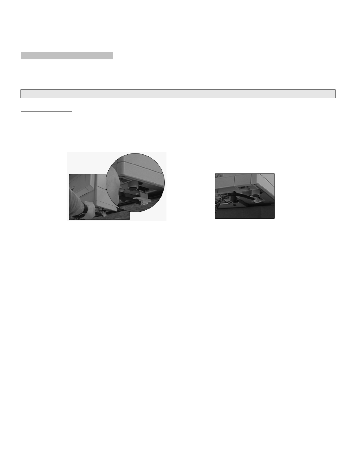
Feeder Installation
1) Remove feeder cable from plastic bag and set power cord aside.
2) Using two people, place iTerra Elite printer on the table’s edge, just slightly, so that the feeder-to-printer cable can
be plugged into its appropriate socket (underneath printer).
3) Return printer to its original position with all four feet in a secure position.
4) Remove feeder from protective packaging.
_________________________________________________________________________________________________________________________
PAGE 11 --- iTerra Elite Quick Start Guide © 2008 iSys-The Imaging Systems Group Inc.
Page 12
5) Insert left and right feeder hooks into corresponding feeder slots on the front opening of the printer.
6) Carefully let feeder down - its weight will secure it to the printer
7) Attach feeder-to-printer cable via connector and secure thumbscrews to the feeder.
_________________________________________________________________________________________________________________________
PAGE 12 --- iTerra Elite Quick Start Guide © 2008 iSys-The Imaging Systems Group Inc.
Page 13

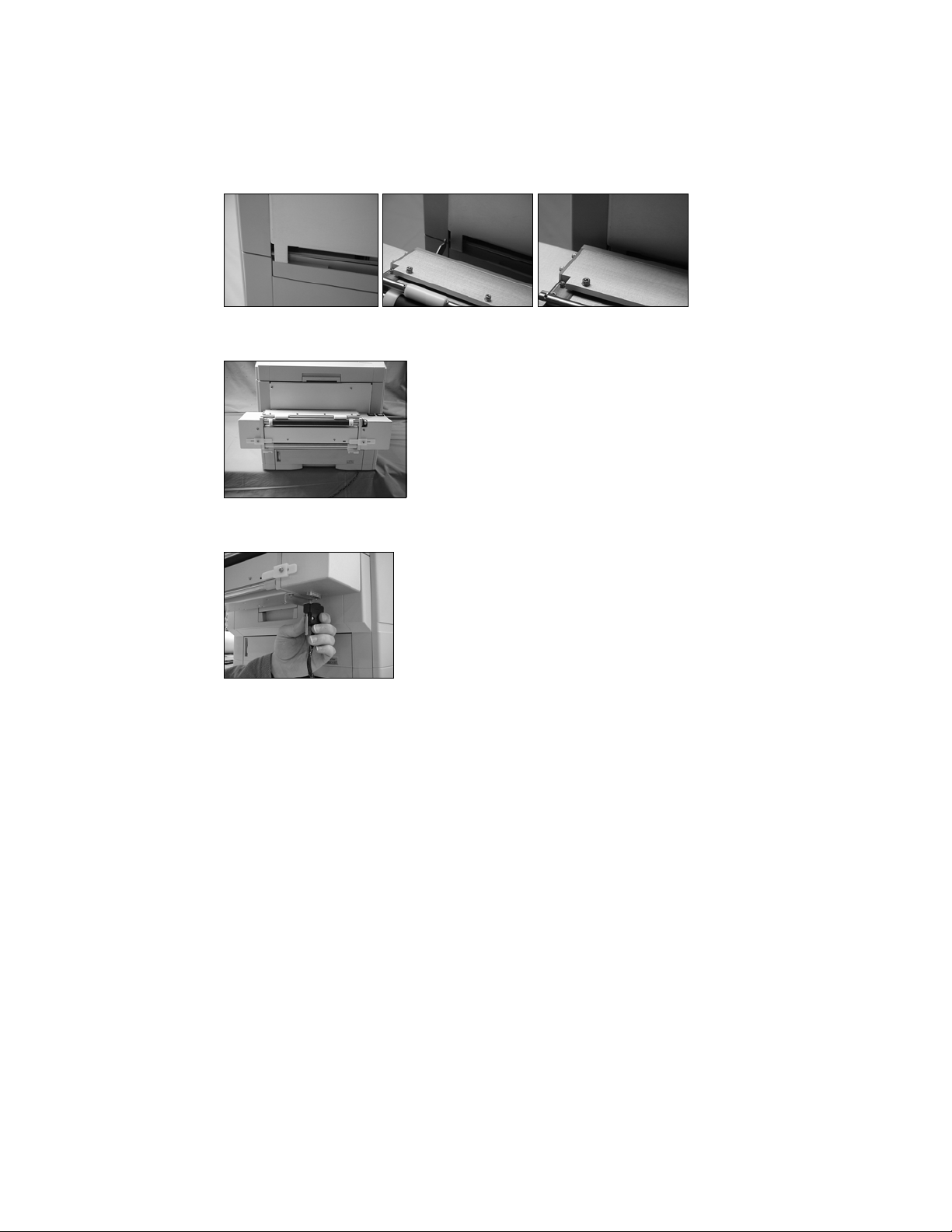
Media Input Tray Installation
1) Remove media input tray from protective packaging.
2) Slide the input tray into the white support brackets of the feeder until the left and right tray locks attach to the
support bracket.
Support Brackets
_________________________________________________________________________________________________________________________
PAGE 13 --- iTerra Elite Quick Start Guide © 2008 iSys-The Imaging Systems Group Inc.
Page 14
3) To release the tray, push up on the locks and pull tray towards you.
Tray Locks
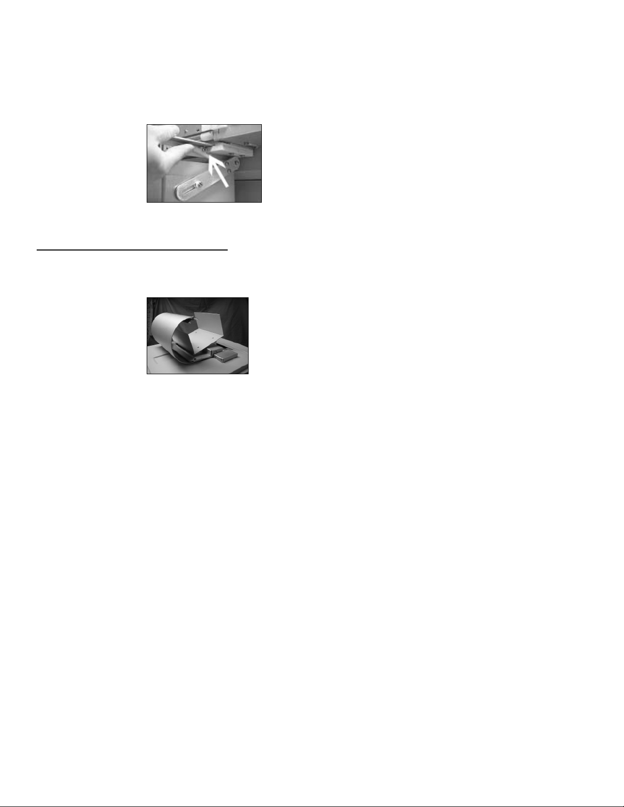
Optional Top Media Stacker Installation
1) Slide the media catcher into the opening on top of the printer. The large radius should be towards the front of the
printer.
_________________________________________________________________________________________________________________________
PAGE 14 --- iTerra Elite Quick Start Guide © 2008 iSys-The Imaging Systems Group Inc.
Page 15

2) The top media stacker must be parallel with the top of the rear jam sensor box, with a 1mm (1/32”) space
between the top media stacker and the jam sensor box.
_________________________________________________________________________________________________________________________
PAGE 15 --- iTerra Elite Quick Start Guide © 2008 iSys-The Imaging Systems Group Inc.
Page 16
III. CONNECT TO POWER
Note: When cycling the printer power (on-off-on), leave the printer power switch in the off position for at least
10 seconds to allow the printer to fully power down before turning it back on again.
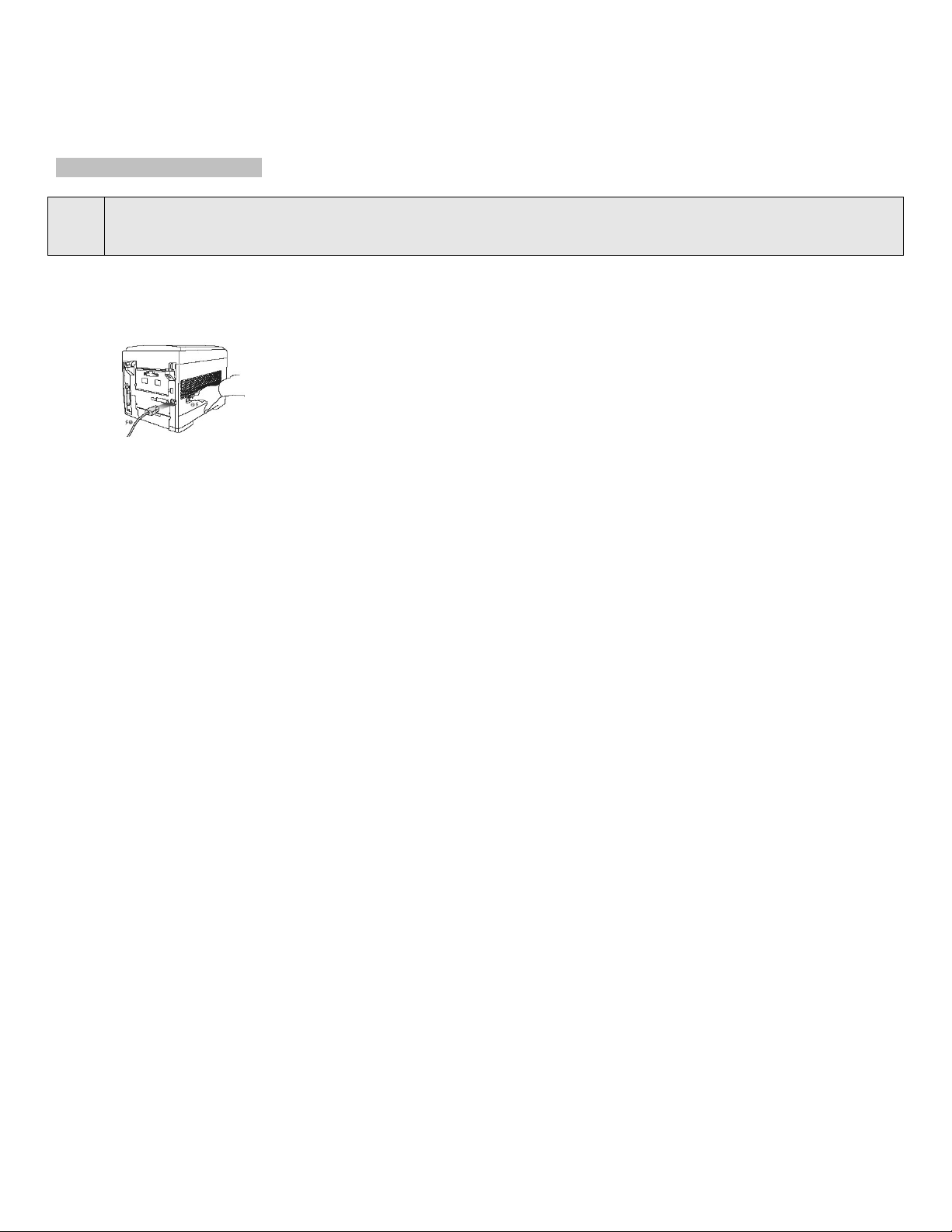
1) Attach the power cord to the back of the printer.
2) Connect to grounded power socket.
3) Turn the printer on and wait for it to warm up. The printer will go through its initialization and warm up sequence.
When the printer is ready, the READY indicator comes on and stays on (green) and the LCD indicates ONLINE.
_________________________________________________________________________________________________________________________
PAGE 16 --- iTerra Elite Quick Start Guide © 2008 iSys-The Imaging Systems Group Inc.
Page 17
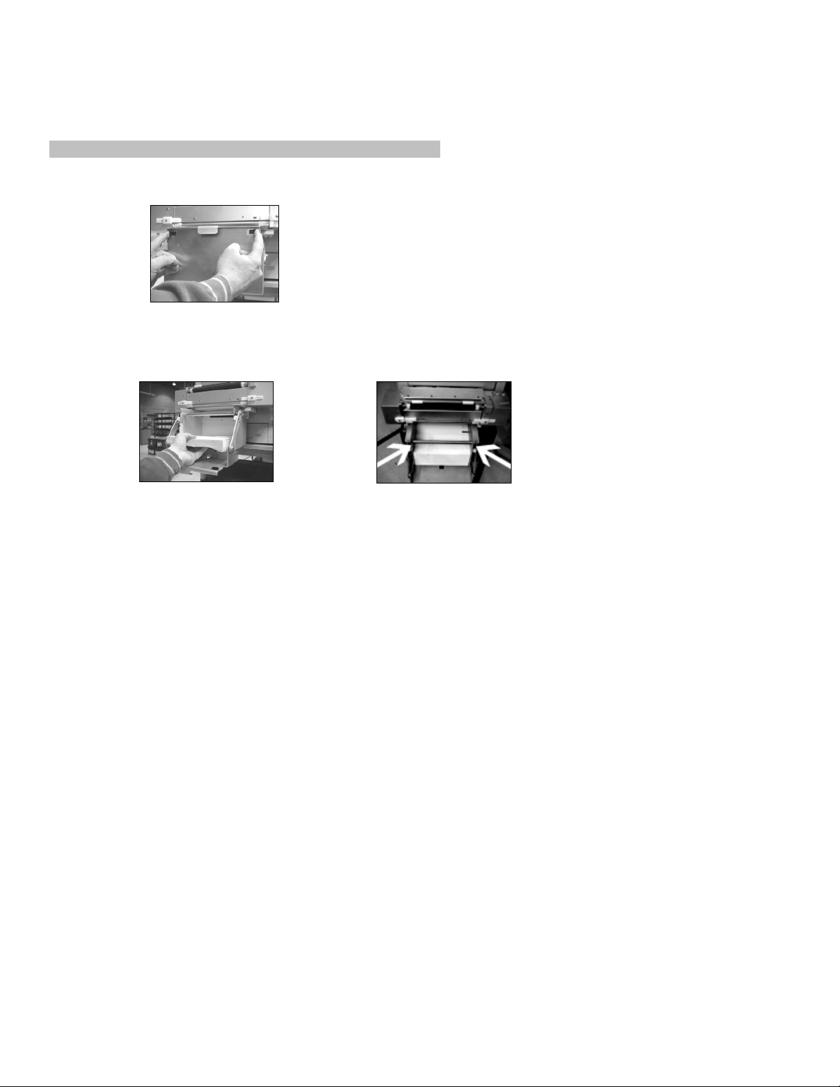
IV. LOADING CONTINUOUS FORM FEED PRINT MEDIA
1) Push right and left snap latches inward to open the tray door and pull it down.
2) Insert continuous fanfold paper so that the black I-Mark (TOF) is positioned towards the back and to the right side
of the tray (See “Print Media Specifications” for paper size).
Tension Bar
_________________________________________________________________________________________________________________________
PAGE 17 --- iTerra Elite Quick Start Guide © 2008 iSys-The Imaging Systems Group Inc.
Page 18

3) Feed leading edge of the paper behind the tension rod.
Tension Bar
4) Load the leading edge of the paper under the pinch roller in a straight and level manner with even margins at the
left and right of the drive roller collars. Manually hold and push the paper in until the leading edge is secure under
the cutter bar.
Cutter
_________________________________________________________________________________________________________________________
PAGE 18 --- iTerra Elite Quick Start Guide © 2008 iSys-The Imaging Systems Group Inc.
Page 19
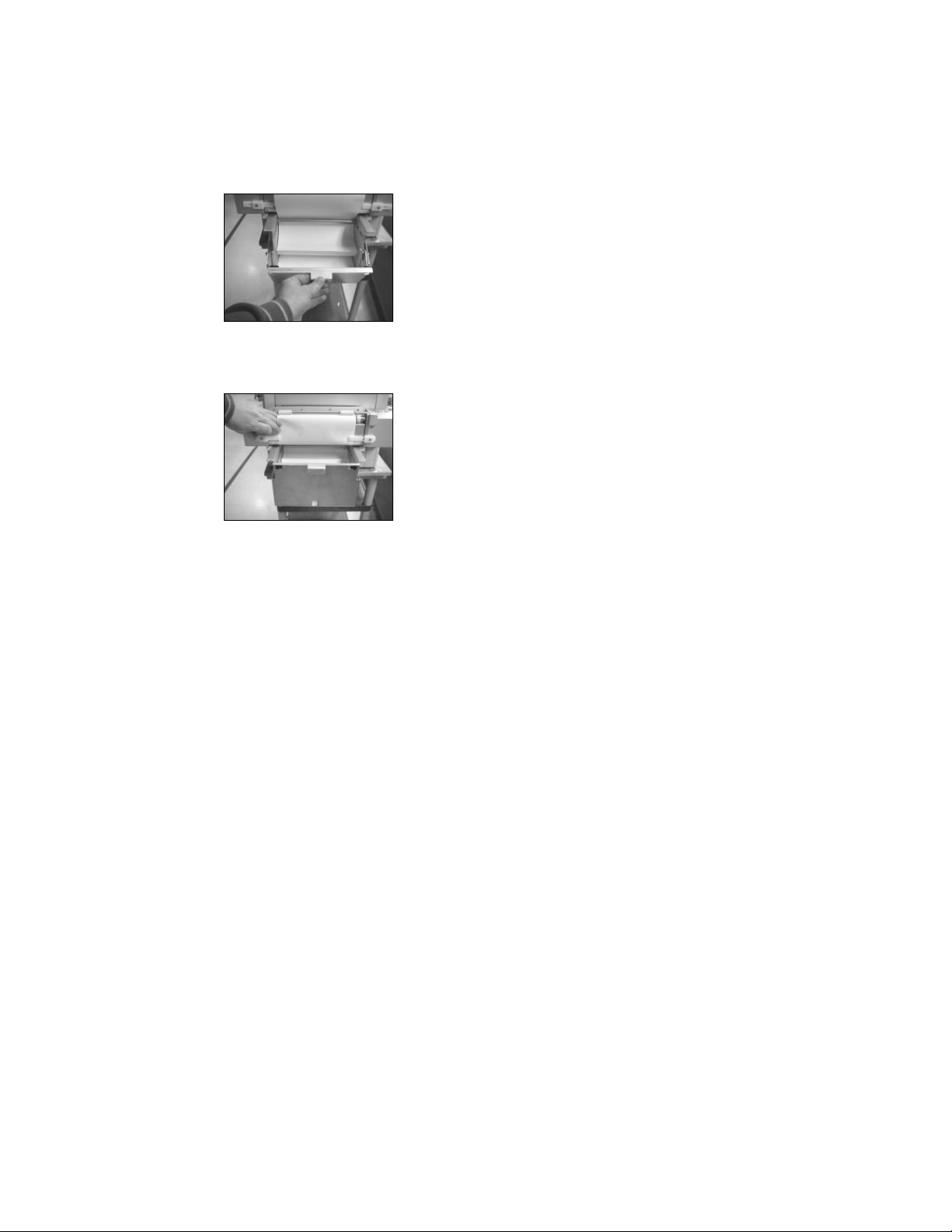
5) Close the tray door firmly until latched.
6) Push the right and left white media-limit slides inward. These ensure constant reading of the I-Mark (TOF) by
sensor.
_________________________________________________________________________________________________________________________
PAGE 19 --- iTerra Elite Quick Start Guide © 2008 iSys-The Imaging Systems Group Inc.
Page 20
7) Press and hold the ADVANCE button on the feeder to load paper. (Hold until green LED stops flashing.) Make
sure the paper has tension.
8) If loading paper from a box of more than 800 fanfold sheets, place box directly in front of printer on the floor. Do
not insert paper into tray but simply feed paper through print media slot on bottom of paper tray. Carry on with
steps (2-7).
9) You are now ready to plot.
NOTE:
Step 7 must be repeated any time the green light is flashing. Cycling the printer on and off, as well as
removing paper from the feeder after a jam or other unintended operation, will cause this light to flash.
_________________________________________________________________________________________________________________________
PAGE 20 --- iTerra Elite Quick Start Guide © 2008 iSys-The Imaging Systems Group Inc.
Page 21

V. PRINT MEDIA PROPERTIES
Standard Paper
WARNING:
Custom:
• Continuous Fan Fold (8.5” wide)
Single Sheet Only:
• Letter, Executive
• Legal-14, legal 13.5, Legal 13
• A4, A5, A6, B4, B5
Using certified iSys Media is critical to your day-to-day operation of this printer. Using non-qualified media
will result in print job failures, poor output quality, lost time and down time. Call iSys Media or your Sales
Representative to learn more about this.
Feed Paths:
• Tray 1
• Paper Tray
Exit Paths:
• Top
• Rear
Weight:
• 16-54 lb. US Bond
_________________________________________________________________________________________________________________________
PAGE 21 --- iTerra Elite Quick Start Guide © 2008 iSys-The Imaging Systems Group Inc.
Page 22
2. ORDERING CONSUMABLE SUPPLIES
I. HOW TO ORDER QUALIFIED MEDIA AND CONSUMABLES
Using non-Qualified iTerra media and
consumables will void the printers’ warranty.
Toll-free by phone at 1-866-415-4797 within North
America or 1-403-204 5200 globally.
By fax at 1-403-204-1971 using an iSys Elite
Media order form.
All prices in US dollars. Credit Card accepted.
Sales tax, Shipping & Handling are added where
applicable.
You can use a purchase order to purchase
products directly from iSys if the order value is over
$500, excluding freight and taxes and if you have
been approved for credit.
Paper
Media iSys Part No.
1000 sht CL85FF1000
3800 sht CL85FF3800
5500 sht CL85FF5500
6000 sht CL85FF6000
Toner Cartridges
Color iSys Part No.
Black
Cyan
Magenta
Yellow
CL2-BKT
CL2-CYT
CL2-MGT
CL2-YWT
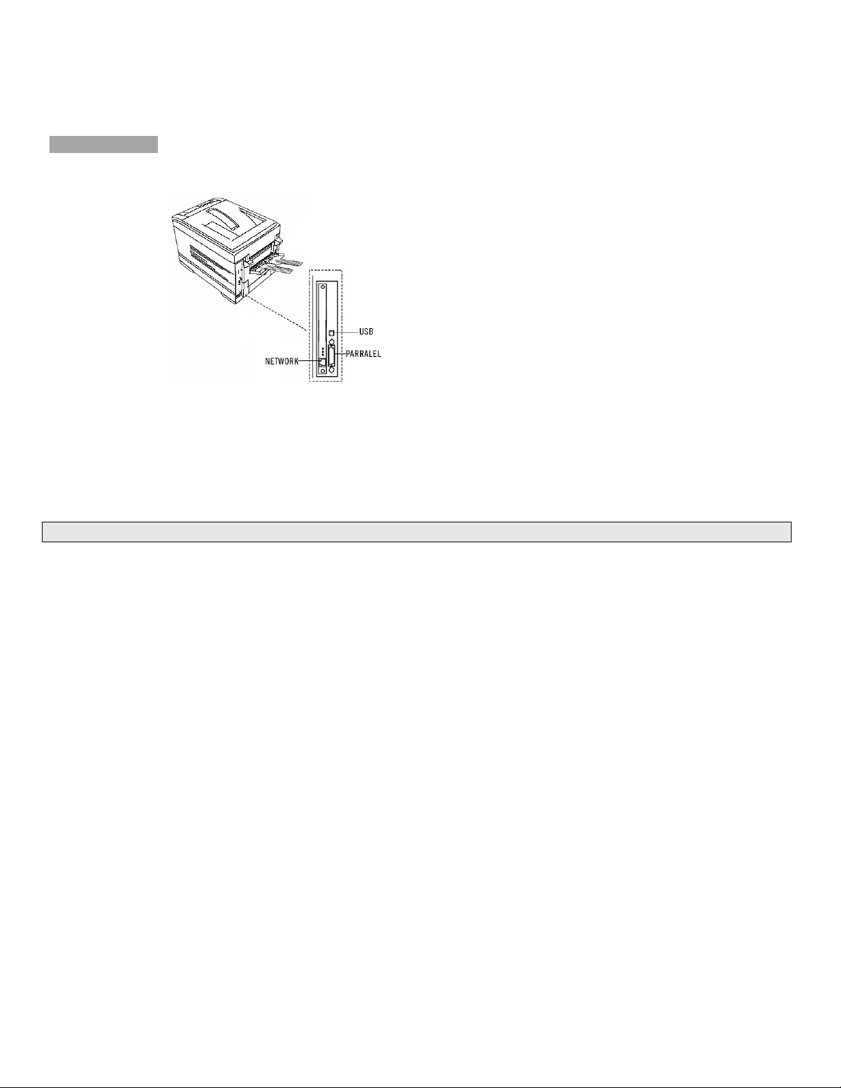
Image Drums
Color iSys Part No.
Black
Cyan
Magenta
Yellow
CL2-BKD
CL2-CYD
CL2-MGD
CL2-YWD
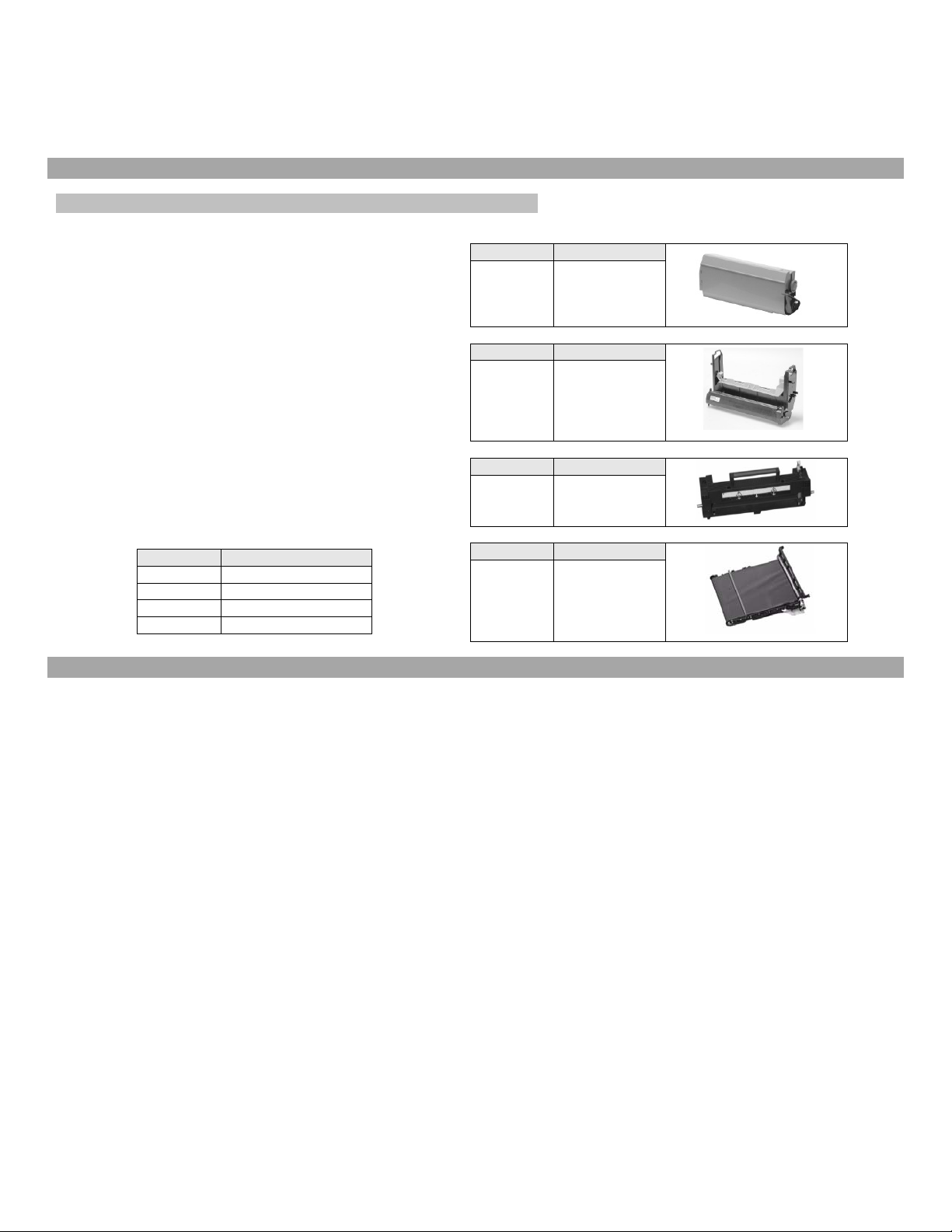
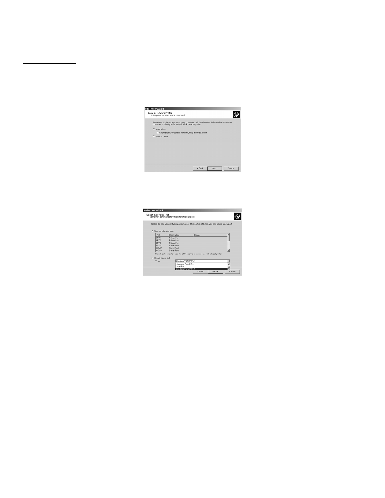
Fusers
Voltage iSys Part No.
120 Volts
230 Volts
CL3-Fuser120
CL3-Fuser230
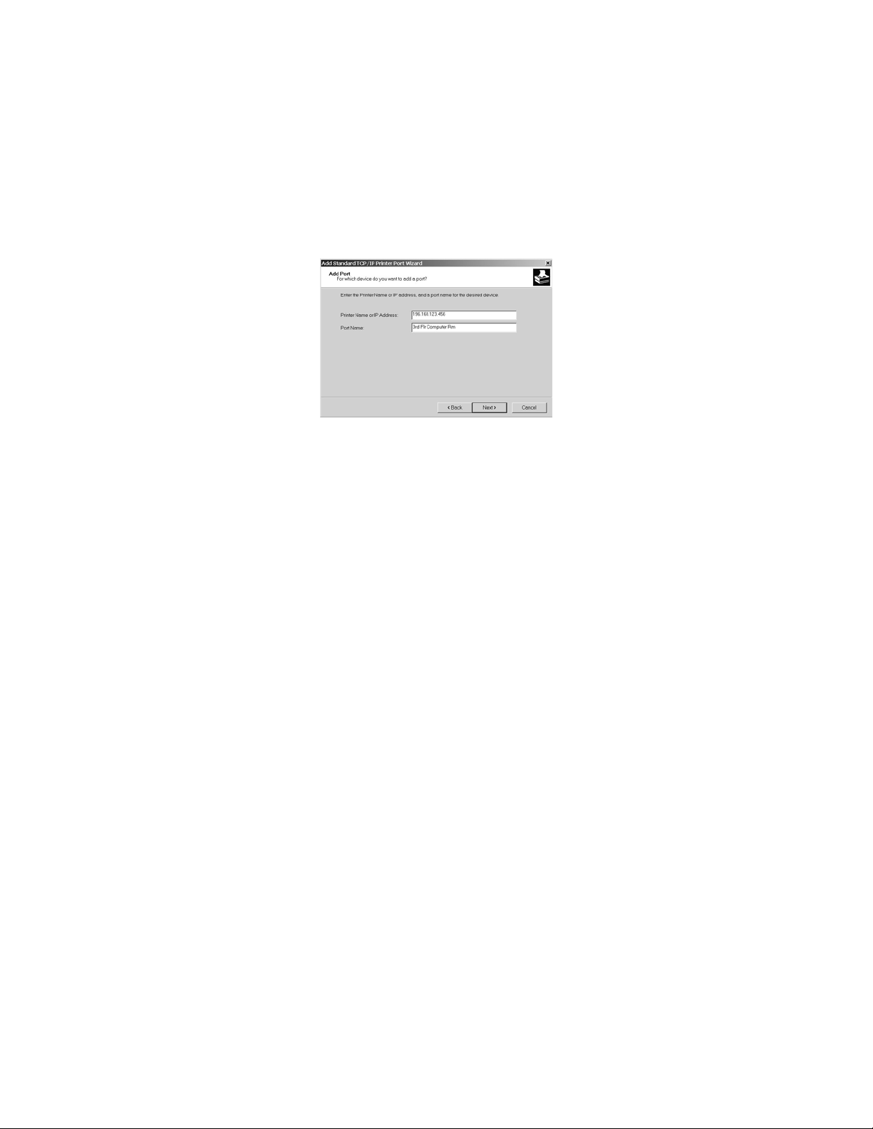
Transfer Belt
Item iSys Part No.
Transfer
CL3-Belt
Belt
3. INTERFACE SETUP AND INSTALLATION
_________________________________________________________________________________________________________________________
PAGE 22 --- iTerra Elite Quick Start Guide © 2008 iSys-The Imaging Systems Group Inc.
Page 23
I. INTERFACES
Your printer is equipped with a selection of data interfaces. See rear of Printer:
1. Parallel – For direct connection to a PC. This requires a bi-directional parallel port with a (IEEE 1284 compliant)
parallel cable.
2. USB – For connection to a PC running Windows XP or Windows 2000. This port requires a cable conforming to
USB version 1.1 or above.
The operation of a printer is not assured if a USB compatible device is connected concurrently with other USBcompatible devices (USB A Male to USB B Male cable).
3. Ethernet – For network cable connection. Optional Network card is required.
NOTE:
Administrator’s authority may be required when installing a network connection.
_________________________________________________________________________________________________________________________
PAGE 23 --- iTerra Elite Quick Start Guide © 2008 iSys-The Imaging Systems Group Inc.
Page 24

II. LOCAL INSTALLATION
A. Parallel Port Connection
1. Turn off both the computer and the printer.
2. Attach a standard IEEE-1284 parallel cable (not supplied) to the parallel port on the printer, securing it
with the spring clips.
3. Attach the other end to the parallel port on the computer and secure it in place with the screws.
B. USB Port Connection
NOTE:
CAUTION:
NOTE:
No USB interface cable is supplied with the printer. Use a USB cable that is compatible with USB
specification 1.1).
Install Windows Driver before powering up printer with USB interface connected to eliminate incorrect
driver being auto installed.
1. Turn off both the computer and the printer.
2. Connect the USB cable to the USB port on the computer.
3. Connect the other end of the cable to the USB port on the printer.
A USB interface will only operate using Windows 2000, Windows XP, Windows Me and
Windows 98). It will not operate using MS-DOS, Windows 95, 3.1, or NT 4.0.
Printer operation is not assured if another USB compatible device is connected
concurrently with it.
If a USB hub is used it must be connected directly to the computer.
_________________________________________________________________________________________________________________________
PAGE 24 --- iTerra Elite Quick Start Guide © 2008 iSys-The Imaging Systems Group Inc.
Page 25

III. NETWORK INSTALLATION
C. Network Port Connection
NOTE:
Ethernet® cable is not supplied with the printer. Use an Ethernet cable with two twisted wire pairs and an
RJ45 plug.
1) Turn the printer off.
2) Connect your Ethernet cable to the network port on the printer (1).
3) Connect the other end of the Ethernet cable to the network port, Hub or host system (2).
4) Turn the printer on and wait for the print server status light (3) to stop blinking.
If you are unaware of what the network IP set value is for the printer, follow the instructions below to determine that value.
You will need to know the printer IP before you can load the printer driver.
If a network configuration card is not already installed refer to Trouble Shooting Chapter and/or Accessory installation (if
network card is purchased later than printer).
_________________________________________________________________________________________________________________________
PAGE 25 --- iTerra Elite Quick Start Guide © 2008 iSys-The Imaging Systems Group Inc.
Page 26

IV. PRINT DRIVER INSTALLATION
Overview Windows 2000 & Windows XP
The iTerra Elite (CLP825) Continuous Printer Driver for Windows 2000 & XP allows users to print directly from Windows
applications to the iTerra Elite printer. These instructions describe installation of drivers from a driver installation CD ROM
or from driver files on your hard disk to the Windows 2000 host system.
Printing can be done through the parallel port, USB port or a network. The printer can be set up as a shared device so
that other Windows host systems on the network can access it although drivers will need to be loaded on each of the host
systems.
Preparation
The following items will be necessary to complete this installation procedure:
1) Be sure that the IP address of the printer has been properly assigned and set. The IP address of the printer is
required in the driver installation. See the next section entitled ‘Network Card IP Address checking and setting’ to
check, change and set the printer’s IP.
2) Ensure that the driver can be accessed on the host system. You may have a CD ROM that was supplied with the
purchase of the printer or you may have downloaded a driver zip file from the www.isys-group.com website. If
you did download a zip file you will have to unpack the files and make note of the location to where you have
unpacked it.
3) It is a good idea to have the Windows 2000 distribution CD available at the time of the driver installation.
_________________________________________________________________________________________________________________________
PAGE 26 --- iTerra Elite Quick Start Guide © 2008 iSys-The Imaging Systems Group Inc.
Page 27
Driver Installation
1) Start the Windows 2000 host system.
2) Click Start-Settings-Printers, and then double-click on the Add Printer icon.
3) This will start the Add Printer Wizard, Click NEXT to continue to the next diagram.
4) Be sure to click LOCAL PRINTER and be sure the AUTOMATICALLY DETECT…box is unchecked as shown.
Click NEXT to continue to the next diagram:
_________________________________________________________________________________________________________________________
PAGE 27 --- iTerra Elite Quick Start Guide © 2008 iSys-The Imaging Systems Group Inc.
Page 28
5) As shown above, select the type of port to which the printer has been connected. If the port selected is not a
network port such as LPT1 or a USB port continue on to section 10). If you are connected on a network, click on
CREATE A NEW PORT, and then select STANDARD TCP/IP PORT. Then click NEXT to continue to the Add
Standard TCP/IP Port Wizard. Click NEXT to continue to the next diagram:
6) In the screen shown above, type the IP address of the printer in the top box (not the same as shown above). A
unique port name will be automatically created in the lower box. This name can be kept (recommended) or it can
be changed to any other name. Click NEXT to continue.
7) Windows will now try to locate and identify the printer on the network. This may take 20-30 seconds. If there is
an error check network connections and IP addresses. If all network connections are correct and Windows
locates the printer, the screen will be displayed, as shown in the next diagram.
_________________________________________________________________________________________________________________________
PAGE 28 --- iTerra Elite Quick Start Guide © 2008 iSys-The Imaging Systems Group Inc.
Page 29
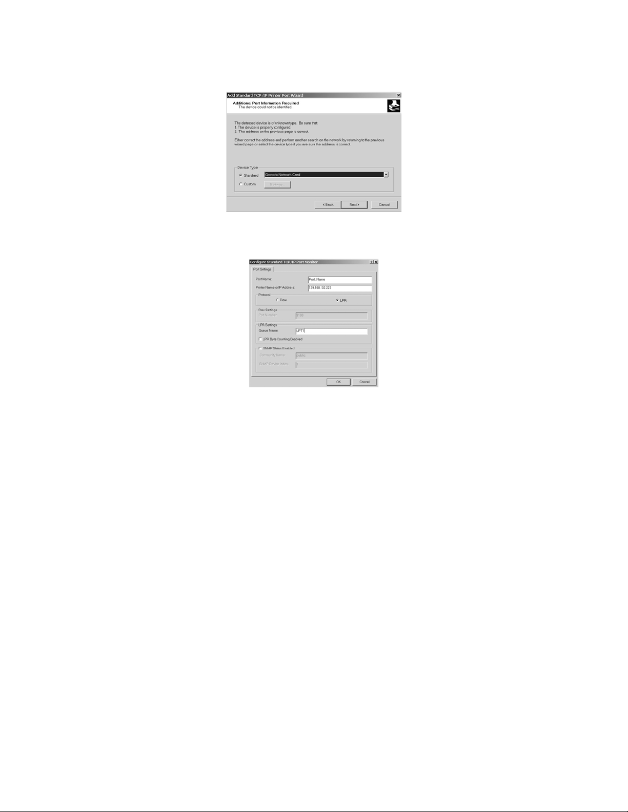
8) This screen indicates that Windows located the printer but does not recognize it. This is not a problem. Click on
CUSTOM and then click on SETTINGS. The next diagram will be displayed:
9) As shown above, click the LPR button in the Protocol box. Then, in the LPR Settings box type in “LPT1” (no
quotes) for the Queue Name. Click OK. This will return you to the previous screen. Click NEXT and on the
following screen click FINISH to complete setting up the LPR port.
_________________________________________________________________________________________________________________________
PAGE 29 --- iTerra Elite Quick Start Guide © 2008 iSys-The Imaging Systems Group Inc.
Page 30

10) The next diagram, should now be displayed.
_________________________________________________________________________________________________________________________
PAGE 30 --- iTerra Elite Quick Start Guide © 2008 iSys-The Imaging Systems Group Inc.
Page 31
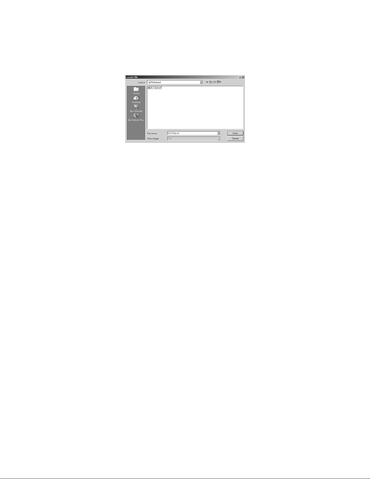
In the above screen click HAVE DISK and then on the following screen click BROWSE. A browser screen like the one in
the next diagram will be displayed.
11) In the example shown above, the driver files were found on a floppy disk in drive A. Depending on the situation
these may also be found on a CD drive, on the hard drive of the host system, or at the networked drive location.
In any case, when file Ok71121e.inf is found, click OPEN and on the next screen click OK.
12) The screen below should be displayed indicating that the iSys CLP825 drivers were found. Click NEXT.
_________________________________________________________________________________________________________________________
PAGE 31 --- iTerra Elite Quick Start Guide © 2008 iSys-The Imaging Systems Group Inc.
Page 32

13) On the next three screens you will be given the option to enter a name for the printer, to share it over a network
and to print a test page. Make the appropriate entries and click NEXT each time.
NOTE:
Printing a test page is recommended, as it will test the LPR connection. However since printing
parameters have not set been set, the print may be less then ideal.
14) On the last screen of the Add Printer Wizard click FINISH. Depending on the system settings a warning screen
may be displayed about the “digital signature” of the drivers. This can be ignored by clicking YES.
NOTE:
It is possible that the system could be set to block unsigned drivers. In that case, change the setting
at Start-Settings-Control Panel. Or contact your system administrator.
_________________________________________________________________________________________________________________________
PAGE 32 --- iTerra Elite Quick Start Guide © 2008 iSys-The Imaging Systems Group Inc.
Page 33

15) At this point the system will need to copy additional driver files and may need to copy system files for the LPR
service. A prompt like the one shown in the next diagram will be displayed.
The exact prompts will depend on settings at the host system. The prompt will generally ask for the Windows
2000 CD, but that is not always necessary.
16) When the entire printer installation process has completed successfully, a new printer icon will be added to the
Printers folder.
_________________________________________________________________________________________________________________________
PAGE 33 --- iTerra Elite Quick Start Guide © 2008 iSys-The Imaging Systems Group Inc.
Page 34

Setting Default Properties
The default properties for the printer just installed can be set as follows:
1) Click START button, then select SETTINGS-PRINTERS to open the Printers folder.
2) Right click on the icon for the Horizon printer. In the drop-down box select PRINTING PREFERENCES.
NOTE:
Another choice in the drop-down box is RENAME. This could be used to change the name of the printer.
Also, SET AS DEFAULT can be used to designate this as the Windows default printer.
3) Click on the Layout tab and then click on the ADVANCED button to access and select default media type and
size, as well as many other settings.
Changing the Printer IP Address
After a printer has been installed on a Windows 2000 host system, its IP address can be changed if that becomes
necessary.
1) Click START-SETTINGS-PRINTERS, then click on the icon for the printer to be changed, select PROPERTIES
and then click on the PORTS tab. The screen should look as shown in the next diagram:
_________________________________________________________________________________________________________________________
PAGE 34 --- iTerra Elite Quick Start Guide © 2008 iSys-The Imaging Systems Group Inc.
Page 35

2) Be sure the port with the iSys printer is selected then click CONFIGURE PORT. The Configure Port Screen will
look as displayed in the next diagram:
3) On the Configure Port screen change the IP address to the new setting.
NOTE:
The Port Name cannot be changed by this procedure. If the Port Name was unacceptable, e.g. if it
includes the old IP address, to change it use Delete Port. The printer and port will have to be fully installed
again.
4) Click on the General tab and make a Windows test print or close the Properties box altogether and send a test
print from a Windows application.
Making a Printer a Shared Device
_________________________________________________________________________________________________________________________
PAGE 35 --- iTerra Elite Quick Start Guide © 2008 iSys-The Imaging Systems Group Inc.
Page 36

If a printer was installed as an unshared device and it is later desired to share it, its status can be changed as follows:
1) Click START-SETTINGS-PRINTERS then right click on the icon for the printer to be changed, select
PROPERTIES and then click on the SHARING tab. The screen should look as shown below.
2) Click the SHARED AS button, which will enable the text box. Type the Share name in the box. Do not click on
ADDITIONAL DRIVERS. Drivers will have to be installed on the client systems that want to share this printer.
Click OK. The printer will appear as a shared resource in Network Neighborhood.
_________________________________________________________________________________________________________________________
PAGE 36 --- iTerra Elite Quick Start Guide © 2008 iSys-The Imaging Systems Group Inc.
Page 37

V. NETWORK CARD IP ADDRESS-CHECKING AND SETTING
The following section enables you to determine the printer’s IP Address as well as how to set it to the desired value. The
following actions will only create results if a network card is presently installed in the printer.
From the front operating panel of the printer, follow the instructions below.
Set IP Address
Set Subnet Mask Address
Set Default Gateway Address
_________________________________________________________________________________________________________________________
PAGE 37 --- iTerra Elite Quick Start Guide © 2008 iSys-The Imaging Systems Group Inc.
Press Button 0
1.
Display will read “NETWORK MENU”
Press Button 1
2.
Display will read “IP ADDRESS 000.000.000.000”
Press Button 1 or 5
3.
Press Button 2 or 6
4.
Press Button 3
5.
Press Button 4
6.
Press Button 0
1.
Display will read “NETWORK MENU”
Press Button 1
2.
Display will read “SUBNET MASK 255.000.000.000”
Press Button 1 or 5
3.
Press Button 2 or 6
4.
Press Button 3
5.
Press Button 4
6.
9 times
once
to select address group to change
to set the desired value
to save changes
to put printer back ONLINE
9 times
5 times
to select address group to change
to set the desired value
to save changes
to put printer back ONLINE
Press Button 0
1.
Display will read “NETWORK MENU”
9 times
Page 38

Press Button 1
2.
Display will read “SUBNET MASK 000.000.000.000”
Press Button 1 or 5
3.
Press Button 2 or 6
4.
Press Button 3
5.
Press Button 4
6.
9 times
to select address group to change
to set the desired value
to save changes
to put printer back ONLINE
VI. WEB BROWSER TO PRINTER (Advanced Users and Administrators)
A Network iTerra Elite printer can also be accessed via a web browser, where default settings can be modified to suit your
User Environment. You will need to know the IP setting (for your web browser URL address input) and the printer name.
The printer name is displayed on the Network Information sheet that is printable as part of the Menu Map (see Printing the
Menu Map section). This name can be found under the Auto Discovery section of the Network Information sheet. The
Username is ‘root’ and the Password is the last six (6) characters of the Printer Name. For example: Printer Name
displayed on the Menu Map printout is ETHERA485C5, therefore the password is A485C5).
NOTE:
Password is case sensitive while the username is not.
_________________________________________________________________________________________________________________________
PAGE 38 --- iTerra Elite Quick Start Guide © 2008 iSys-The Imaging Systems Group Inc.
Page 39

VII. WINDOWS 2000 & XP PRINT DRIVER PROPERTIES
Open the printing properties page, through the Printers folder (START Æ SETTINGSÆ PRINTERS) then right click on the
printer name, and selecting the PROPERTIES box.
This will open a window
to the following Æ
VIII. GENERAL TAB
This window tab displays general information such as the printer name
(iSys CLP825), allows the user to view and set the ‘PRINTING
PREFERENCES’ (see the Printing Preferences doc) and lets you print a
windows test page from the ‘PRINT TEST PAGE’ button.
_________________________________________________________________________________________________________________________
PAGE 39 --- iTerra Elite Quick Start Guide © 2008 iSys-The Imaging Systems Group Inc.
Page 40

VIX. SHARING TAB
From this windows screen the user can enable printer sharing on their host
computer.
X. PORTS TAB
Allows the user to select or change the connectivity from the host computer
to the iSys printer (see the driver installation doc for more information on
setting up a TCP/IP port).
_________________________________________________________________________________________________________________________
PAGE 40 --- iTerra Elite Quick Start Guide © 2008 iSys-The Imaging Systems Group Inc.
Page 41

XI. ADVANCED TAB
This window allows the user to change the printers’ availability, which
will spool up the jobs until the appropriate available time; spooler
options and you can have the spooler create a separator page between
jobs if required.
XII. COLOR MANAGEMENT TAB
You can add a color profile if color matching is important. (See Printer
Preferences for more information).
_________________________________________________________________________________________________________________________
PAGE 41 --- iTerra Elite Quick Start Guide © 2008 iSys-The Imaging Systems Group Inc.
Page 42
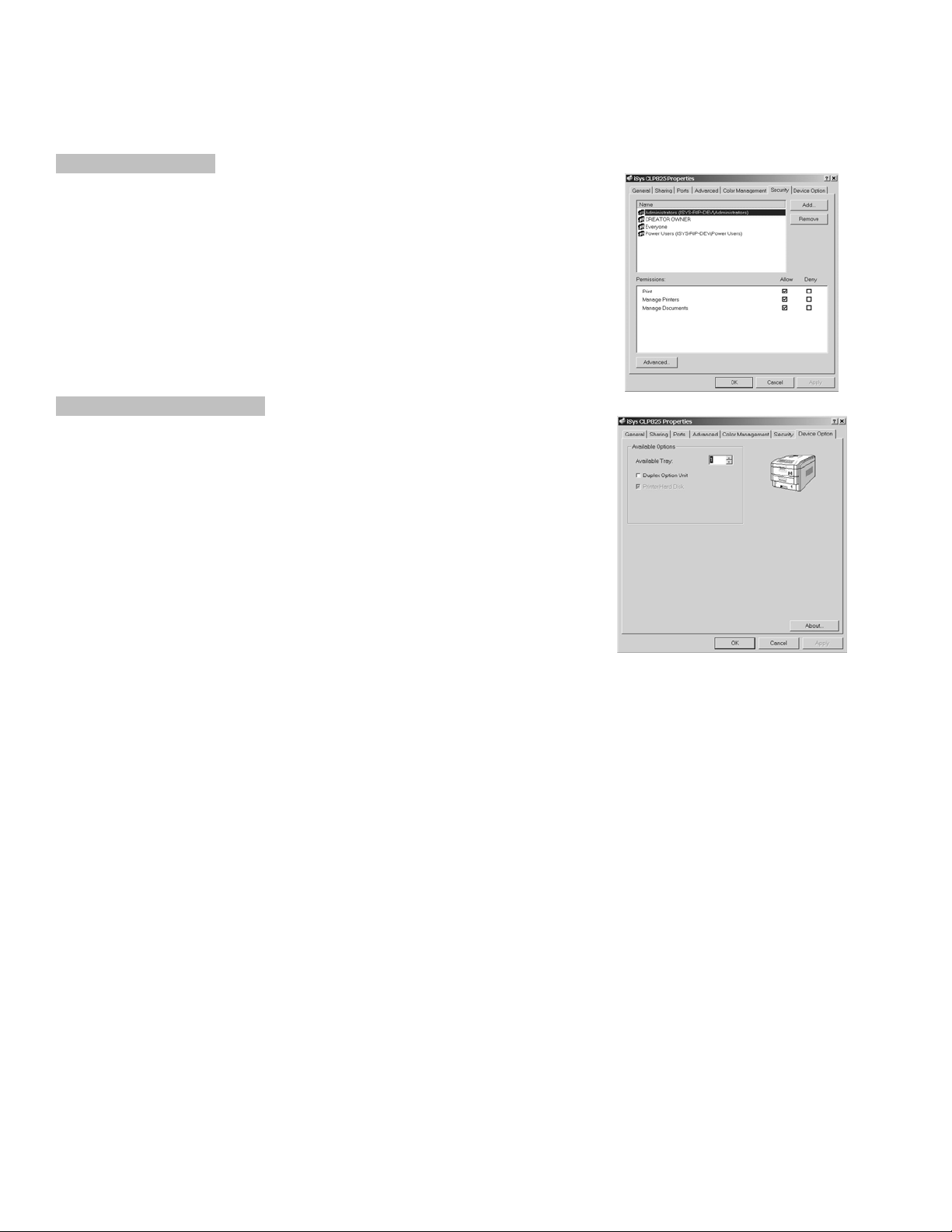
XIII. SECURITY TAB
You can allow specific users access to the printer on the host computer.
This is usually only changed if the printer is being shared on a network.
XIV. DEVICE OPTION TAB
This window is typically not changed unless a duplexer has been added
and is not used if running continuous media.
_________________________________________________________________________________________________________________________
PAGE 42 --- iTerra Elite Quick Start Guide © 2008 iSys-The Imaging Systems Group Inc.
Page 43

4. OPERATION – CONTINUOUS PAPER MODE
I. PRINTER CONTROL PANEL OVERVIEW
• Attention indicator (red). ON indicates that attention is required, but printing will continue. FLASHING indicates
that attention is required, but printing will stop.
• Ready indicator (green). ON - ready to receive data. FLASHING indicates processing data or error.
• Liquid crystal display (LCD) panel. Two rows of up to 24 alphanumeric characters displaying print status, menu
items in menu mode, and error messages.
_________________________________________________________________________________________________________________________
PAGE 43 --- iTerra Elite Quick Start Guide © 2008 iSys-The Imaging Systems Group Inc.
Page 44

Menu button
Press briefly to enter the MENU mode. Press briefly again to select the
next menu. Press for more than 2 seconds to scroll through the
different menus.
Item (+)
Press briefly to scroll forward to the next menu item.
button
Value (+)
button
Select button
Online button
Press briefly to scroll forward to the next value setting for each menu
item.
Press briefly to select the menu, item or value indicated on the LCD.
Switches between online and offline status
When pressed in MENU mode, it returns the printer to on line
status.
When pressed with DATA PRESENT displayed, it forces the
printer to print out the remaining data in the printer.
When there is an error message indicating wrong paper size,
pressing the ONLINE button forces the printer to print.
Item (–)
Press briefly to scroll backward to the previous menu item.
button
Value (–)
button
Cancel
Press briefly to scroll backward to the previous value setting for each
menu item.
Press to cancel a print job.
button
_________________________________________________________________________________________________________________________
PAGE 44 --- iTerra Elite Quick Start Guide © 2008 iSys-The Imaging Systems Group Inc.
Page 45

II. FEEDER OPERATING INSTRUCTIONS
Loading Continuous Media
1) Manually load media
2) Turn on printer
3) The switch panel lights will illuminate in sequence during the feeder boot up.
4) Once the green light begins flashing on the feeder switch panel (media pre-load required), push and hold the
ADVANCE button until green light stops flashing and remains on (ready for printing)
NOTE:
Feeder Switch Panel Functions
Feeder Switch Panel Indicators
The paper feeder will not automatically load the paper into the printer until Step 4 is completed. Step 4 must be
repeated any time the green light is flashing. This condition will exist if the printer is cycled off and on or if paper is
cleared from the feeder after a paper jam.
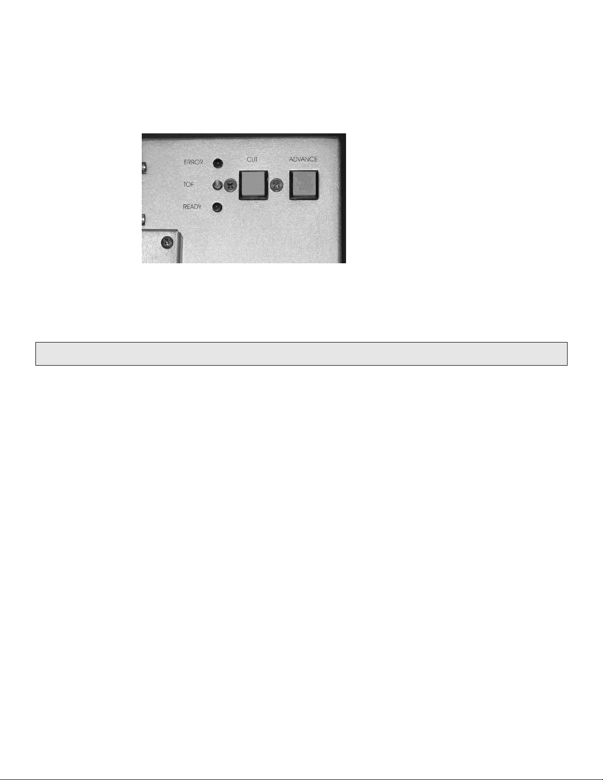
Cut Button
Pressing this button for 2 seconds will actuate a paper cut operation.
Cut paper must be cleared out from paper feeder.
Advance
Button
Pressing and holding this button will activate the paper pre-load
sequence. This button becomes locked out (inactive) during printing or
if the green light is on steady.
_________________________________________________________________________________________________________________________
PAGE 45 --- iTerra Elite Quick Start Guide © 2008 iSys-The Imaging Systems Group Inc.
Page 46

Red
Flashing means an error condition was encountered. Please call iSys
service at 1-866-415-4797. See chapter 6, Troubleshooting, for more
information.
Yellow
ON means TOF sensor sees the black I-Mark. OFF means a TOF
sensor sees white paper.
Green
Flashing means that a paper pre-load is required. Steady means that
the printer is ready for printing.
_________________________________________________________________________________________________________________________
PAGE 46 --- iTerra Elite Quick Start Guide © 2008 iSys-The Imaging Systems Group Inc.
Page 47

III. EXIT SPEEDS AND PRINT CONTROLS
To select exit location (Back or Top) or to adjust print quality from the front panel of the printer the following steps must be
performed:
1) Push button 4 (online button 1x). Printer must be OFFLINE before working in the extended menu. This will
ensure that a print job does not print while modifying the settings.
2) Push Buttons 6 and 7 together and hold for a few seconds and release. Fan Fold print control.
3) Push Button 1 (item button 1x). This will display the current paper exit location. (Example: Exit: Top
Status: Good)
4) Using Button 2 or 6 (value button + or -) allows the user to scroll through the menu options. There are
currently six options available under Fan Fold Print Control.
5) To change the current setting scroll through the menu options using buttons 2 and 6 until the desired option
is displayed on the screen.
6) Push button 3 (select button 1x). Option saved.
7) Cycle Print Power. Check print quality. Display on printer will remain blank for up to 45 seconds before
returning Online, this is normal.
(If you continue to experience print quality difficulty, please contact iSys Technical Support at 1-866-415-5797).
Printer Front Panel
How to print test plot on disk:
Press Button 0
_________________________________________________________________________________________________________________________
PAGE 47 --- iTerra Elite Quick Start Guide © 2008 iSys-The Imaging Systems Group Inc.
Option 1: Exit: Back Status: Stall
Option 2: Exit: Back Status: Smear
Option 3: Exit: Back Status: Good
Option 4: Exit: Top Status: Stall
Option 5: Exit: Top Status: Smear
Option 6: Exit: Top Status: Good
once
Page 48

Display will read “PRINT JOBS MENU”
Press Button 3
Display will read “ENTER PASSWORD ****”
Press Button 2
Display will read
Press Button 1
Display will read
Repeat previous
2 steps 3 times
until Display
reads
Press Button 3
Display will read “SELECT JOB
Press Button 2
Press Button 3
Display will read
Press Button 3
once
twice
“ENTER PASSWORD 1***”
once
“ENTER PASSWORD 1***”
“ENTER PASSWORD 1111”
once
ALL JOBS”
until the Display reads
“iTerraElite_Demo”
once
“Set Collating Amount”
1
to plot test file selected. Printer will go
back ONLINE.
How to print a Menu Map (Printer Configuration):
Press Button 0
Display will read “INFORMATION MENU”
Press Button 3
Display will read “PRINT MENU MAP EXECUTE”
Press Button 3
_________________________________________________________________________________________________________________________
PAGE 48 --- iTerra Elite Quick Start Guide © 2008 iSys-The Imaging Systems Group Inc.
2 times
once
once more to print the menu map. Printer
Page 49

will go back ONLINE.
How to change number of copies:
Press Button 0
Display will read “PRINT MENU”
Press Button 3
Display will read “COPIES 1*”
Press Button 2
Press Button 6
Press Button 3
Press Button 4
4 times
once
to increase # of copies desired
to decrease # of copies
to save change
to put printer back ONLINE
_________________________________________________________________________________________________________________________
PAGE 49 --- iTerra Elite Quick Start Guide © 2008 iSys-The Imaging Systems Group Inc.
Page 50

IV. OUTPUT VIA BACK
Press Buttons 6 & 7
Display should read
Press Button 1
Display should read “Fanfold Print Control
Smearing
Press Button 2
Display should read
Press Button 3
Display should read
Press Button 4
Display should read
Cycle the printer’s power
Run Test Plot to check quality of plot
Repeat these steps until image quality is
acceptable
NOTE:
Ensure you are only changing the Status for where your media is exiting the printer.
once
“Fanfold Print Control
Exit: Back Status:
Smear ”
once to save change
“Fanfold Print Control
Exit: Back Status:
Smear *”
once to put printer back
ONLINE
“Cycle Printer Power
Check Print Quality”
at same time
“Fanfold Print Control”
once
Exit: Back Status: Good *”
(Default)
Jamming
Press Button 2
Display should read “Fanfold Print Control
Press Button 3
Display should read “Fanfold Print Control
Press Button 4
Display should read “Cycle Printer Power
Cycle the printer’s power
Run Test Plot to check quality of plot
Repeat these steps until JAMMING in front of fuser
stops
twice
Exit: Back Status:
Stall”
once to save change
Exit: Back Status: Stall
*”
once to put printer back
ONLINE
Check Print Quality”
_________________________________________________________________________________________________________________________
PAGE 50 --- iTerra Elite Quick Start Guide © 2008 iSys-The Imaging Systems Group Inc.
Page 51

V. OUTPUT VIA TOP (Using optional top stacker)
Press Buttons 6 & 7
Display should read
Press Button 1
Display should read
Press Button 6
Display should read
at same time
“Fanfold Print Control”
once
“Fanfold Print Control
Exit: Back Status: Good *” (Default)
3 times to select Exit out the Top of the printer.
“Fanfold Print Control
Exit: Top Status: Good ”
_________________________________________________________________________________________________________________________
PAGE 51 --- iTerra Elite Quick Start Guide © 2008 iSys-The Imaging Systems Group Inc.
Page 52

Smearing
Press Button 2
Display should read
Press Button 3
Display should read “Fanfold Print Control
Press Button 4
Display should read “Cycle Printer Power
Cycle the printer’s power
Run Test Plot to check quality of plot
Repeat these steps until image quality is acceptable
once
“Fanfold Print Control
Exit: Top Status: Smear
”
once to save change
Exit: Top Status: Smear
*”
once to put printer back
ONLINE
Check Print Quality”
NOTE:
Ensure you are only changing the Status for where your media is exiting the printer.
Jamming
Press Button 2
Display should read
Press Button 3
Display should read
Press Button 4
Display should read “Cycle Printer Power
Cycle the printer’s power
Run Test Plot to check quality of plot
Repeat these steps until image quality is acceptable
twice
“Fanfold print Control
Exit: Top Status:
Stall
once to save change
“Fanfold Print Control
Exit: Top Status: Stall
*”
once to put printer back
ONLINE
Check Print Quality”
_________________________________________________________________________________________________________________________
PAGE 52 --- iTerra Elite Quick Start Guide © 2008 iSys-The Imaging Systems Group Inc.
Page 53

VI. OUTPUT PROBLEMS
Jamming
For Continuous Plotting Fanfold a JAM could occur in 4 places.
1) Feeder green LED is flashing.
• Media is not loaded-press and hold ADVANCE button until green LED stops flashing.
2) Front of the printer while Feeder is loading.
• Check leading edge of media for damage.
• Check the pinch roller.
• Check to see if media is loaded correctly through the input tray.
• Load motor might need calibration.
3) Front of the Fuser
• Leading edge of paper is damaged (curls or bends).
• EXIT Speed is too slow.
4) Behind the Fuser or past the EXIT of the printer.
TOP
• Paper may not be folding properly in the Top Stacker tray.
• Check to see if the Top Stacker is installed correctly. Check the distance to the JAM box.
BACK
• Check to see if the cable is installed on the Rear Jam block.
• Make sure paper is free to fall to the floor.
_________________________________________________________________________________________________________________________
PAGE 53 --- iTerra Elite Quick Start Guide © 2008 iSys-The Imaging Systems Group Inc.
Page 54

Smearing:
• Consumables not installed correctly or non-iSys brand.
• Paper moisture content is too high. Check for pock
marking.
• Paper width not within specification.
• Paper not tracking properly through the feeder
• Exit Speed too slow.
Creasing or Wrinkling:
• Consumables not installed correctly or non-iSys brand.
• Paper moisture content is too high. Check for pock
marking.
• Paper width not within specification.
• Paper not loading square to the front feed roller in the
printer.
_________________________________________________________________________________________________________________________
PAGE 54 --- iTerra Elite Quick Start Guide © 2008 iSys-The Imaging Systems Group Inc.
Page 55

5. PRINT DRIVER PREFERENCES
This chapter explains how to set up color printing and how to use the printer’s features from within the driver preferences.
Most of these features are designed for sheet operation via Tray 1, yet many also apply to continuous ‘super long page’
operation via modified multi purpose tray.
NOTE:
Most applications allow the printer properties to be accessed from within the document print dialog box.
_________________________________________________________________________________________________________________________
PAGE 55 --- iTerra Elite Quick Start Guide © 2008 iSys-The Imaging Systems Group Inc.
Page 56

I. CHANGING THE iSys CLP825 PRINTING PREFERENCES
There are few ways a user can open the printing preferences page:
through the Printers folder
START Æ SETTINGSÆ PRINTERS
then right click on the printer name
or when using an applications
FILE Æ PRINT OPTIONS and
selecting the PROPERTIES box
or from the iSys CLP825
PROPERTIES page
_________________________________________________________________________________________________________________________
PAGE 56 --- iTerra Elite Quick Start Guide © 2008 iSys-The Imaging Systems Group Inc.
Page 57

II. THE SET UP TAB
There are 4 subsections under the SETUP tab:
A. Media
B. Finishing Mode
C. 2-Sided Printing
D. Driver Settings
_________________________________________________________________________________________________________________________
PAGE 57 --- iTerra Elite Quick Start Guide © 2008 iSys-The Imaging Systems Group Inc.
Page 58
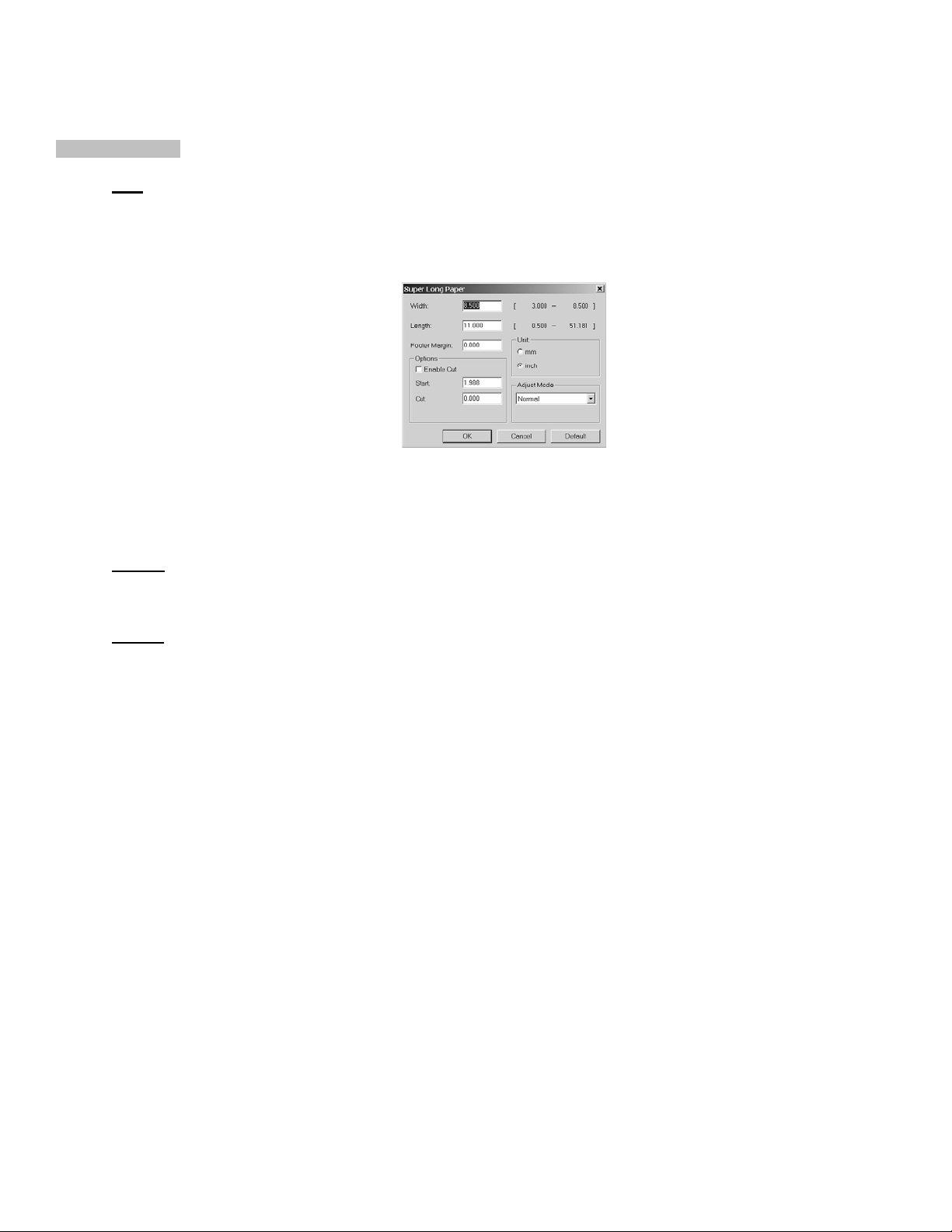
A. Media Section
Size
Drop down list of various standard sheet paper sizes and default ‘Super Long Paper’. Select ‘Super Long
Paper’ for continuous printing operation. Default Super Long Paper specification is for 20-24lb paper with a width
of 8.5” and support to 400’ in length. For a complete Super Long Paper specification sheet, notify your sales
Representative. This will open a window as follows:
From here you can toggle the ‘Enable Cut’ option if the user requires a cut between multi-copy jobs. You can
also adjust the ‘START’ field, which changes the distance where the image is placed. You might use this if you
would like to adjust the distance from the leading edge of paper or the initial tear-perforation using continuous
media. This ‘CUT’ field adjusts where the cut occurs.
Source
Allows the user to change the printer paper tray to be used. For continuous plotting the only tray that can be used
is the ‘Multi Purpose Tray’, the remaining standard sheet tray is labeled ‘Tray1’.
Weight
You can change the media weight (media type and thickness). For continuous plotting the default should be
‘Printer Setting’.
_________________________________________________________________________________________________________________________
PAGE 58 --- iTerra Elite Quick Start Guide © 2008 iSys-The Imaging Systems Group Inc.
Page 59

The ‘Paper Feed Options’
The user should not have to change anything on this menu other than for generating a user defined ‘Custom
Super Long Paper’ size or Custom Size. The default settings have been optimized for continuous printing.
Fit to Page
For sheet printing functions, this toggle will resize the image to fit the source paper size.
Cover Printing
For sheet printing, this allows the user to select another source for the first page of the print job. With only one
sheet tray in the printer, this is likely an unused function.
Paper Feed Options
“Auto Tray Change” toggle is likely not used due to only one paper tray available, would allow the printer to
automatically select a second source for same size paper. “Media Check” toggle will let the printer sense the
paper before printing, checking for thickness and adjusting the print properties automatically.
Multi Purpose Tray Settings
Toggle to make the Manual Paper Tray slot to be manual feed with human interaction required. Not for use with
Continuous Media printing, or when an automated feeder is attached.
Custom Size or Custom Super Long Paper Sizes
These two types are virtually the same, with Custom Super Long Paper having the additional functions to activate
or modify the start, cut positions, etc. Custom page sizes can only be printed via the multi purpose tray. The paper
(media) size for the multi purpose tray must be manually set in the driver to the custom paper size before use.
Custom page sizes range:
• Width: 3½ to 8½ inches [89 to 216 mm], • Length: 5 to 14 inches [127 to 356 mm]
NOTE:
Up to 32 custom page sizes can be defined in the driver.
1.) Open the file in your application. Select FILE Æ PRINT.
_________________________________________________________________________________________________________________________
PAGE 59 --- iTerra Elite Quick Start Guide © 2008 iSys-The Imaging Systems Group Inc.
Page 60

2.) In the Print dialog box, on the GENERAL tab, click the appropriate driver. Click the SETUP tab.
3.) Under MEDIA, in the SIZE drop-down list, select USER DEFINED SIZE. The Set Free Size dialog box
appears.
4.) Select the unit. Enter the width and length measurements. Custom page sizes can be defined provided they
fall within the following ranges:
• Width: 3.0 to 8.5 inches [76.2 to 215.9 mm]
• Length: 0.5 to 51.181 inches [12.7 to 1300.0 mm]
1. Click OK.
2. Make sure that USER DEFINED
now appears in the SIZE list on the SETUP tab.
Default
This button will reset the driver ‘Paper Feed’ preferences to the original or default values.
_________________________________________________________________________________________________________________________
PAGE 60 --- iTerra Elite Quick Start Guide © 2008 iSys-The Imaging Systems Group Inc.
Page 61

B. Finishing Mode Section
If ‘Super Long Paper’ is selected this field is deactivated. If a standard sheet type media is selected for output
the following applies and is available. Use the dropdown style and make a selection or press the ‘Options’ button
to call up the Standard / N –up dialogue box.
Standard / N-up
This allows you to print multiple pages on one sheet, with each page image reduced in size.
Pages per Sheet:
This function reduces the image size of each page so that the desired number of pages will fit on a single
page. With each selection, the preview area will change. Please confirm the page layout in the preview
area.
1: Prints one page on one sheet of paper (default)
2: Prints 2 pages on one sheet of paper
4: Prints 4 pages on one sheet of paper
6: Prints 6 pages on one sheet of paper
8: Prints 8 pages on one sheet of paper
9: Prints 9 pages on one sheet of paper
16: Prints 16 pages on one sheet of paper
_________________________________________________________________________________________________________________________
PAGE 61 --- iTerra Elite Quick Start Guide © 2008 iSys-The Imaging Systems Group Inc.
Page 62

NOTE:
Data is not laid out centered on the page. The reduced image for the first page will be pasted to the
upper left corner of the actual page. Fit to Page and Scale factor options, if used, will affect the position
of the pages on the printed sheet. Fit to Page is applied first, then N-up, and finally Scale. Use the
Preview area to check the effects of your changes.
Border
For N-up selections other than 1, you may select a page border to surround each individual page image that will
be printed on the single sheet of paper.
Page layout
You can set the page order, if multiple images per page are selected.
Bind Margin
Reduces the size of the image to be printed and ads a margin for binding the document.
Poster Print
When Poster Print is selected one-page print data is enlarged into multiple pages.
Enlarge
2: One page is enlarged into 2 pages.
4: One page is enlarged into 4 pages.
9: One page is enlarged into 9 pages.
Custom: A user can select a number of pages. 1x1 ~ 4x4.
Custom
When Custom is selected the Settings button is enabled. Clicking the Settings button will open the Custom
setting dialog window.
Add Registration Marks
_________________________________________________________________________________________________________________________
PAGE 62 --- iTerra Elite Quick Start Guide © 2008 iSys-The Imaging Systems Group Inc.
Page 63

When checked, crop marks are added.
Specify the color of crop marks, if click Color button.
Add Overlap
When checked, overlap is added.
Sets the amount of pile part.(0.01~0.79 inch , 0.1~20.0 mm)
C. 2-Sided (Duplex) Printing Section
This will always be disabled unless a duplexer is installed. This option can never be used with continuous printing
job. If outfitted with a Duplexing unit, three options are available: None, Long Edge and Short Edge.
None
The printer does not print on both sides of the paper.
Long Edge
Pages are bound on the long-edge (length). For portrait orientation, the backside of the page is printed in the
same direction as the front side. This will give a printed result that is easy-to-read when the document is bound
on the left side or the right side. For landscape orientation, the backside of the page is printed in the opposite
direction to the front side. This will give an easy-to-read print result when the document is bound at the top or the
bottom.
Short Edge
Pages are bound on the short-edge (width). For portrait orientation, the backside of pages is printed in the
opposite direction to the front side. This will give an easy-to-read print result when the document is bound at the
_________________________________________________________________________________________________________________________
PAGE 63 --- iTerra Elite Quick Start Guide © 2008 iSys-The Imaging Systems Group Inc.
Page 64

top or the bottom. For landscape orientation, the backside of pages is printed in the same direction as the front
side. This will give an easy-to-read print result when the document is bound on the left side or the right side.
NOTE:
This function is not available unless a Duplex Option Unit is installed. Once the Duplex Option Unit is
installed in your printer, open the Paper tab in Printer Properties and press the Device Options button.
Place a check by the Duplex Option Unit to activate it.
D. Driver Settings
This function will SAVE the user defined settings in the driver to a user-controlled filename.
Set Names: Sets the settings selected on the list under the saved set name.
Add: Displays the dialog to enter the set name and saves the driver settings under the set name.
Remove: Removes the selected Set Names from the list.
Whether or not to include saving of the settings in Paper Group can be selected on the dialog to
enter Set Names.
_________________________________________________________________________________________________________________________
PAGE 64 --- iTerra Elite Quick Start Guide © 2008 iSys-The Imaging Systems Group Inc.
Page 65

III. THE JOB OPTIONS TAB
There are 4 subsections and 5 subsection buttons under
the Job Options tab:
A. Quality
B. Orientation
C. Job Type
D. Scale
E. Watermark
F. Overlay
G. Font
H. Advanced
I. Default
A. Quality
Used to select the desired resolution. The ‘Toner Saving’ check box is used for limiting the amount of toner used during
printing, this will affect the quality of the output and is equivalent to a ‘Draft’ copy.
B. Orientation
Standard printing options are Portrait or Landscape printing. The 180º option is for rotating each page 180 degrees. This
does not flip the entire job, but each individual page. When ‘Super Long Page’ is the paper size, this option is restrictive.
C. Job Type
Select the desired job type. Default values of ‘Normal’ with no ‘PIN’ are recommended for regular use.
_________________________________________________________________________________________________________________________
PAGE 65 --- iTerra Elite Quick Start Guide © 2008 iSys-The Imaging Systems Group Inc.
Normal
Page 66

Specify this for normal printing.
Proof and Print
When printing multiple copies of a document, Proof and Print allows you to verify (Proof) the first copy
before printing the remaining copies. The first copy is printed normally. The remaining copies can be
printed (or deleted) upon entering your PIN and selecting the document at the printer's control panel, via
the ‘Print Jobs Menu’. At the Printers Control Panel, Press the MENU button on the control panel. The
PRINT JOBS menu is displayed. Press the SELECT button. A password is requested for access to print
jobs (enter value of 1111). Then press the VALUE+ button until the job that you want to print is displayed
in the PRINT JOBS menu. Press the SELECT button and you will be prompted to provide the PIN ID that
you gave the print job. Enter the PIN and press SELECT, the proof document will begin printing.
Secure Print
The Secure Print selection provides a mechanism for controlling when a confidential or important
document will be printed. Printing will not begin until you enter the security Printer Identification Number
(PIN) that you defined as a part of the print job at the control panel of the printer. Press the MENU button
on the control panel. The PRINT JOBS menu is displayed. Press the SELECT button. A password is
requested for access to print jobs (enter value of 1111). Then press the VALUE+ button until the job that
you want to print is displayed in the PRINT JOBS menu. Press the SELECT button and you will be
prompted to provide the PIN ID that you gave the print job. Enter the PIN and press SELECT, the secure
document will begin printing.
NOTE:
The first entry in the list is "ALL JOBS”, so ensure that you have selected the correct job.
_________________________________________________________________________________________________________________________
PAGE 66 --- iTerra Elite Quick Start Guide © 2008 iSys-The Imaging Systems Group Inc.
Page 67

Store to HDD
This command sends and stores the print job on printer hard disk. Job is then printed via the printer control
panel by accessing the ‘Print Jobs Menu’. At the Printers Control Panel, Press the MENU button on the
control panel. The PRINT JOBS menu is displayed. Press the SELECT button. A password is requested for
access to print jobs (enter value of 1111). Then press the VALUE+ button until the job that you want to print is
displayed in the PRINT JOBS menu. Press the SELECT button and you will be prompted to provide the PIN
ID that you gave the print job. Enter the PIN and press SELECT, the stored document will begin printing.
• For the Proof and Print, Secure Print and Store to HDD functions, an internal printer hard disk must be
installed.
• When you install a printer hard disk, check Printer Hard Disk in Device Option tab. In addition, a PIN is
required.
• If the hard disk memory is insufficient for the spooled data, DISK FULL is displayed and expectant output
maybe compromised.
• If the software application being used has a collate print option, it must be turned OFF for proof and print
to operate correctly. Proof and print may not be available in some software applications.
• Jobs can be deleted off of the printers disk drive by the following procedure:
Press the MENU button to access the PRINT JOBS MENU a press the SELECT button.
1. Enter PASSWORD number using the buttons on the printer control panel. (Password is 1111).
2. Press the VALUE button until ALL JOBS or the required job name is displayed.
3. Press the CANCEL button to delete the job.
4. When the deletion confirmation message appears, confirm by pressing the SELECT button.
Copies
Enter the number of copies you wish to have printed.
Collate
Prints the document with the pages in ascending numerical order for multiple-copy printing.
D. Scale
_________________________________________________________________________________________________________________________
PAGE 67 --- iTerra Elite Quick Start Guide © 2008 iSys-The Imaging Systems Group Inc.
Page 68

This allows you to set a rate to enlarge or reduce your printed image. The image size may be adjusted over a range of
25%-400%.
When "Disabled" item is checked, it notifies that the driver does not have a scaling function capability. If ‘Super Long
Paper’ is the media size selection, this option is unavailable. Some software applications may not be able to utilize this
function.
E. Watermarks
In the Watermark dialog, you set watermark print related items. A watermark is a graphic or text that is layered over an
existing image. If you use the Watermark function, you can print the characters on top of the data you have created in an
application program. Select a watermark from the list. The selected watermark can be edited. When (None) is selected,
no watermark will be printed. Watermarks can be added, edited and removed from the list. If you wish for the watermark
to appear ONLY on the first page, activate the First Page Only box.
Create a New watermark by pressing the ‘New’ button. Entering the text string that you wish, modify the Font or Color by
activating the buttons and working through the sub-layer dialogue boxes. Modify the Position and the Angle of orientation.
The Trim function allows for different border around the text. Press OK to complete the Create New dialogue.
_________________________________________________________________________________________________________________________
PAGE 68 --- iTerra Elite Quick Start Guide © 2008 iSys-The Imaging Systems Group Inc.
Page 69

Edit a watermark follows a similar dialogue as New Watermark. (see diagrams to follow).
Remove
a watermark from the list. Select watermark on list and then press ‘Remove’.
Default will return this Tab and the modified values back to the original set values.
_________________________________________________________________________________________________________________________
PAGE 69 --- iTerra Elite Quick Start Guide © 2008 iSys-The Imaging Systems Group Inc.
Page 70

F. Overlay
The Overlay tab allows you to apply additional information to your printed documents.
An Overlay is a single page document, or pieces of a document that have been stored on the printer's hard disk or flash
memory. Examples of overlays include company logos, purchase order forms, or commonly used items within your
documents. The result is similar to the Watermark feature, but with the ability to be much more elaborate.
As an example, Overlays can be used to create a corporate letterhead that is applied to your business letters. The logo
and address that make up the letterhead reside in the printer. This insures that the letterhead appears consistent when
applied by multiple uses, and reduces the amount of data being sent to the printer.
_________________________________________________________________________________________________________________________
PAGE 70 --- iTerra Elite Quick Start Guide © 2008 iSys-The Imaging Systems Group Inc.
Page 71

Basic Steps for Using Overlays:
1. Create the overlay. Many Windows applications can be used to design forms and overlays. After proofing
your overlay, use the 'print to file' feature to create a PRN file representing the overlay.
2. Store the Overlay in the printer's hard disk drive (HDD) or flash memory. The Storage Device Manager utility
can be used to download the PRN file to the printer's hard disk or flash memory. Record the ID values
assigned to each overlay stored in the printer. Notify your sales representative to get your free copy of
Storage Device Manger utility.
3. Select the Overlay tab in Printer Properties, then press the Define Overlays button to add information about
the overlays stored in your printer. You can indicate specific pages for applying the overlay and combine
multiple overlay ID values into a single user-defined Overlay name.
4. Add one or more of the Defined Overlays to the list of Active Overlays by selecting the Overlay Names, then
pressing the Add button. Enable Print Using Active Overlays to apply the overlay(s) to the next printed
document. While this is enabled, all future print jobs will use this overlay until the Print Using Active Overlays
function is disabled. This setting can also be enabled from an application for a particular document. After the
document prints, the Print Using Active Overlays option automatically reverts to a disabled state when the
application is closed.
5. To modify an existing Overlay, follow the steps shown below:
a. Select an item to be changed from the Defined Overlays list.
b. Enter an Overlay name to be added to Overlay Name.
c. Enter up to 3 Overlay ID numbers, separated by commas in the ID value(s) edit box.
d. Select the pages that are to be printed using the Overlay from the Print on Pages list.
e. If you selected Custom in Step (4), enter the page numbers or range of pages to be printed,
separated by commas in the Custom Pages edit box.
_________________________________________________________________________________________________________________________
PAGE 71 --- iTerra Elite Quick Start Guide © 2008 iSys-The Imaging Systems Group Inc.
Page 72

f. Press the Apply button to save the changes to an existing Defined Overlay, or press the Add button
if you have created a new Defined Overlay.
g. Press the Close button when you are finished creating or editing Defined Overlays.
6. If you have made changes to the Active Overlays dialog, press either the Apply button or OK button to
preserve these changes. Press the Cancel button to close the dialog without saving your changes.
When you check ‘Print using active overlays’, the active overlay feature is turned on.
Active Overlays
Displays the list of one or more overlays that may be applied to a document. The initial settings will display an
empty ‘Active Overlays’ window.
To add to the list of Active Overlays, select one or more of the Defined Overlays and press the Add button. You
may add up to 4 Overlays to the list at one time. Use the Remove button to delete an overlay from the list of
Active Overlays.
_________________________________________________________________________________________________________________________
PAGE 72 --- iTerra Elite Quick Start Guide © 2008 iSys-The Imaging Systems Group Inc.
Page 73

Defined Overlays
Displays the list of user-defined overlays. Defined Overlays can be made Active Overlays by selecting the
desired item(s) and pressing the Add button. Up to 4 Defined Overlays can be added to the Active Overlay list at
one time. Initially this list will be blank.
Edit this list by pressing the Define Overlay button, then provide information about the overlay stored in your
printer. When the information is complete, press the Add button. This adds the current overlay information to the
Defined Overlay list.
The Defined Overlay list may contain up to 32 overlays.
_________________________________________________________________________________________________________________________
PAGE 73 --- iTerra Elite Quick Start Guide © 2008 iSys-The Imaging Systems Group Inc.
Page 74

ID Value
Enter the ID of the overlay stored in your printer. This ID represents the PCL macro ID value assigned when
using Storage Device Manager. The range of valid ID numbers is from 0 to 32767.
Up to 3 ID values can be specified to create a single overlay from three different PCL macros. Separate the ID
numbers with commas. (Example: 32, 7, 125). Macros will be executed in the order that they are entered.
Specifies the pages that will be printed using the overlay. Select from the list of pre-defined pages shown below,
or select Custom to define specific pages.
Print On Pages
All pages
First page
Even pages
Odd pages
Custom: Overlay is printed on the pages entered in Custom Pages.
Custom Pages
Allows you to define a range of pages or specific pages to be printed with the overlay when Custom is selected
from the Print on pages list.
Enter a range of pages and/or specific page numbers, separated by commas. (Example: 1,3,6, 4-8).
You can specify pages in the range from 1 to 999.
Follow these instructions to transfer your .prn overlay to the Elite printers hard drive.
_________________________________________________________________________________________________________________________
PAGE 74 --- iTerra Elite Quick Start Guide © 2008 iSys-The Imaging Systems Group Inc.
Page 75

NOTE:
Connectivity Type
1) Parallel Connect Instructions
• Open a DOS command Prompt window and CD (change directory) to the appropriate host directory
• Type the following to send overlay .prn to printer ‘copy/b filename lpt1:’ and hit return or enter.
2) Network Connect Instructions
• Open a DOS Command Prompt window and CD (change directory) to the appropriate host directory
• Use lpr command to send overlay .prn file to the printer, as follows from command prompt window.
3) USB Connect Instructions
• to print via USB connection, you will need to install ‘Free Raw Print’ utility. This is a freeware utility
• Use Free Raw Print application to print overlay .prn file. Ensure that printer highlighted is the iTerra
• The printer windows driver should be installed first and configured.
• The printer should be powered on and connection type configured.
• Use this method if you do not have the Storage Manager Utility.
where the overlay file is loaded.
where the overlay file is loaded.
“lpr-S ip_address-P lp1:filename”
available on the World Wide Web.
Elite and browse for the demo plot file, select and hit print within FRP utility.
_________________________________________________________________________________________________________________________
PAGE 75 --- iTerra Elite Quick Start Guide © 2008 iSys-The Imaging Systems Group Inc.
Page 76

G. Font
In the Font tab, you set TrueType font and printer font related items.
TrueType Font Output Type
Download as Outline Font
TrueType font is downloaded to the printer as outline font and the font image is created inside the
printer. Using this option, the processing load in the Windows operating system, in general,
becomes small, and the processing load in the printer becomes large. Certain TrueType fonts,
however, are downloaded as bitmap fonts, regardless of this setting.
Download as Bitmap Font:
TrueType font is downloaded as a bitmap font to the printer. In this case, the font image is
created in Windows and sent to the printer. In general, this increases the processing load in
Windows and decreases the processing load in the printer.
_________________________________________________________________________________________________________________________
PAGE 76 --- iTerra Elite Quick Start Guide © 2008 iSys-The Imaging Systems Group Inc.
Page 77

Font Substitution
With this checked, the Font Substitution Table becomes available.
Font Substitution Table
Substitutes Printer Fonts for TrueType Fonts. A printer font is selected on the Printer Font list that
substitutes for a font selected on the TrueType font list. This is enabled only when Font
Substitution is checked.
Default
Returns this tabs values to their original settings.
H. Advanced
This tab contains a cross section of switch type settings. The toggled items as displayed in the image below are
the suggested values for Super Long Paper operation.
_________________________________________________________________________________________________________________________
PAGE 77 --- iTerra Elite Quick Start Guide © 2008 iSys-The Imaging Systems Group Inc.
Page 78

Image Quality
This sliding scale makes nominal adjustments balancing Speed versus Quality using an algorithm.
Keep Page Layout with Scale Change
When you use Pages per Sheet (N-up), Fit to page, Bind Margin, or Booklet function, the number of
characters per line or the number of lines per page may change, which results in a different page layout.
When you select this setting, you can use one of these functions without changing the page layout.
However, be aware that you may have a different print result because fill-pattern of a figure or etc. is
enlarged/reduced when you select this setting.
Express Correctly Drawing of Combine
When overlaid colors in a figure, etc. are not precisely printed, selecting this setting may solve the
problem. However, doing so may result in a slower printing speed.
Always create 100% Black (K) Toner
Check this box to have the color Black always generated with black only toner. If un-checked, the color
Black may be generated using a combination of toner colors, creating a poor rendition of black.
Adjust ultra fine lines
By activating this feature, fine lines will be more precisely drawn and displayed.
Priority is given to AP collation
This allows your software application to override the printer preferences collate function, giving priority to
the software application.
Run maintenance cycle before printing
Depending upon printing habits and usage patterns, running the maintenance cycle prior to printing may
insure best possible print quality.
Job Spool
_________________________________________________________________________________________________________________________
PAGE 78 --- iTerra Elite Quick Start Guide © 2008 iSys-The Imaging Systems Group Inc.
Page 79

If a hard disk drive in installed on the printer, this function will move the job print spooling to the printer to
perform and not the host system. This will result in slower printing.
Reduce Size of Spool File
Selecting EMF (Enhanced Metafiles) as a spooling file format reduces the time that the printer needs to
return processing to the application after it starts printing. With some applications, the size of spooling file
becomes huge when EMF is selected as a spooling file format. In that case, select this setting.
This setting is disabled because spooling in EMF format is not available in the following cases:
When you select Print directly to the printer
When you select Always spool RAW data type
When you print from a client side with print server in network environment
This setting is valid only with Windows NT4.0/2000/XP.
I. Default
Returns the values in this tab to the original values.
_________________________________________________________________________________________________________________________
PAGE 79 --- iTerra Elite Quick Start Guide © 2008 iSys-The Imaging Systems Group Inc.
Page 80

IV. COLOR TAB
Factors that Affect Color Printing
The PCL printer driver supplied with your printer provides several controls for
changing the color output. For general use the default driver settings produce good
results for most documents. Many applications have their own color settings and
these may override the settings in the printer driver. Please refer to the your
software application documents for details on how that particular program’s color
management functions. If you wish to manually adjust the color settings in your
printer driver, please be aware that color reproduction is a complex topic and there
are many factors to take into consideration. Some of the most important factors are:
the differences between the range of colors a monitor can reproduce versus
the range of colors that a printer can reproduce
viewing conditions
printer driver color settings
monitor settings
how your software application displays color
paper type
Monitor Colors vs. Printer Colors
(Differences between the range of colors a monitor or printer can reproduce)
Neither a printer nor a monitor is capable of reproducing the full range of colors visible to the human eye. Each
device is restricted to a certain range of colors. In addition to this, a printer cannot reproduce all of the colors
displayed on a monitor and vice versa.
Both devices use very different technologies to represent color. A monitor uses Red, Green and Blue (RGB)
phosphors (or LCDs), a printer uses Cyan, Yellow, Magenta and Black (CMYK) toner or ink.
_________________________________________________________________________________________________________________________
PAGE 80 --- iTerra Elite Quick Start Guide © 2008 iSys-The Imaging Systems Group Inc.
Page 81

A monitor can display very vivid colors such as intense reds and blues. These cannot be easily produced on any
printer using toner or ink. Similarly, there are certain colors, (some yellows for example), that can be printed, but
cannot be displayed accurately on a monitor. This disparity between monitors and printers is often the main
reason that printed colors do not match the colors displayed on screen.
Viewing Conditions
A document can look very different under various lighting conditions. For example, the colors may look different when
viewed standing next to a sunlit window, compared to how they look under standard office fluorescent lighting.
Printer Driver Color Settings
The driver settings for Manual color can change the appearance of a document. There are several options available to
help match the printed colors with those displayed on screen. These options are explained below.
Monitor Settings
The brightness and contrast controls on your monitor can change how your document looks on-screen. Additionally, your
monitor color temperature influences how "warm" or "cool" the colors look. There are several settings found on a typical
monitor:
5000k* Warmest; yellowish lighting, typically used in graphics arts environments.
6500k* Cooler; approximates daylight conditions.
9300k* Cool; the default setting for many monitors and television sets.
*k = degrees Kelvin, a measurement of temperature
How your Software Application Displays Color
Some graphics applications such as CorelDRAW® or Adobe® Photoshop® may display color differently from "office"
applications such as Microsoft® Word. Please see your application’s online help or user manual for more information.
Paper Type
The type of paper used can also significantly affect the printed color. For example, a printout on recycled paper can look
duller than one on specially formulated glossy paper.
_________________________________________________________________________________________________________________________
PAGE 81 --- iTerra Elite Quick Start Guide © 2008 iSys-The Imaging Systems Group Inc.
Page 82

V. COLOUR MATCHING
Choosing a Method
There are many factors involved in achieving accurate and reproducible color. The following guidelines may help in
achieving good color output from your printer. There are several suggested methods, depending on the type of document
you are printing:
most common [RGB]
professional desktop publishing and graphics [CMYK]
photographic images
specific colors (i.e., a company logo)
printing vivid colors
RGB or CMYK?
The guidelines for choosing a color matching method make distinctions between Red, Green, Blue (RGB) and Cyan,
Magenta, Yellow, Black (CMYK). Generally, most documents you print are in RGB format. This is the most common
format. If you do not know your document’s color mode, assume that it is RGB. Typically, CMYK documents are only
supported in professional Desktop Publishing and Graphics applications.
Matching Photographs
RGB only Color Matching is a generally a good choice. Select a matching method appropriate to your monitor.
Matching Specific Colors
(Example: Company logo)
RGB only
Color Matching , and the sRGB setting:
Use the Color Swatch Utility to print out a chart of RGB swatches and enter your desired RGB values in your
application's color picker.
_________________________________________________________________________________________________________________________
PAGE 82 --- iTerra Elite Quick Start Guide © 2008 iSys-The Imaging Systems Group Inc.
Page 83

If you are printing from a graphics application such as Adobe Photoshop, you may be able to use Soft-
Proofing to simulate the printed image on your monitor. To do this, you can use the ICC profiles provided.
Print using the ICC profiles as the Print Space (or Output space).
Printing Vivid Colors
RGB only Use Color Matching, with the Monitor 6500k Vivid, sRGB or Digital Camera settings.
The Color Matching Options in the driver can be used to help match your printed colors to the ones displayed on your
monitor.
Manually set the options in the PCL driver:
1. Click STARTÆ SETTINGS Æ PRINTERS
2. Right click the appropriate printer name. Click PRINTING PREFERENCES
3. Click the COLOR tab
4. Under Color Mode, click MANUAL COLOR
5. Under Color Setting, click NATURAL
6. Select the method you wish to use:
Monitor (6500k) Perceptual
Optimized for printing photographs when using a monitor with a color temperature of 6500K.
Monitor (6500k) Vivid
Optimized for printing bright colors when using a monitor with a color temperature of 6500K. Ideal for
office graphics.
Monitor (9300k)
Optimized for printing photographs when using a monitor with a color temperature of 9300K.
Digital Camera
Optimized for printing photographs taken with a digital camera. This tends to produce prints with lighter
and brighter colors. For some photographs, other settings may be better depending on the subjects and
the conditions under which they were taken.
sRGB
_________________________________________________________________________________________________________________________
PAGE 83 --- iTerra Elite Quick Start Guide © 2008 iSys-The Imaging Systems Group Inc.
Page 84

Optimized for matching specific colors, such as a company logo color. The colors within the printer's color
gamut are printed without any modification, and only colors that fall outside the printable colors are
modified.
7. Set any other required parameters. Use the on-line Help for guidance.
8. When you are done, click OK. Close the Printing Preferences dialog box.
Print Color Swatch Utility
For use with applications, which allow you to set your own RGB values for colors. The Color Swatch utility prints out
charts of sample colors. Listed below each color are the corresponding RGB (Red, Green, Blue) values to use in your
application to match that printed color. Example: You wish to print a logo in a particular shade of red. Follow these steps:
1. Click STARTÆ SETTINGS Æ PRINTERS
2. Right click the printer name. Click PRINTING PREFERENCES.
3. Click the COLOR tab
4. Click the COLOR SWATCH button to print the color swatch samples
5. Select the shade of red that best suits your needs. Make a note of the RGB value below that particular shade
6. Use your program’s color picker to enter the same RGB values (from step 5). Change the logo to that color
Windows ICM Color Matching
• ICM is the color management system built into Windows
• Affects RGB data only
• Can be associated with the PCL driver Windows ICM uses ICC profiles for your monitor and printer
_________________________________________________________________________________________________________________________
PAGE 84 --- iTerra Elite Quick Start Guide © 2008 iSys-The Imaging Systems Group Inc.
Page 85

These profiles describe the colors that your device is capable of reproducing. ICC profiles can be associated with your
printer via the COLOR MANAGEMENT tab of the printer driver. Depending on how you have installed the printer driver,
the color profiles may already be associated with the driver. To associate ICC Color Profiles with the printer driver:
1. Click START Æ SETTINGS Æ PRINTERS
2. Highlight the printer name. Click FILE, then PROPERTIES
3. Click the COLOR MANAGEMENT tab
4. Under “Color Profiles currently associated with this printer”, you should see the names of profiles that match your
printer model. If you do not see any profiles associated with the driver, click “Add…” and locate the ICC profiles
for your printer
Windows ICM uses the information in these profiles to convert colors in your documents to colors that the printer can
reproduce. The way in which this conversion is performed can be controlled via the ICM Intent control in the printer
driver.
_________________________________________________________________________________________________________________________
PAGE 85 --- iTerra Elite Quick Start Guide © 2008 iSys-The Imaging Systems Group Inc.
Page 86

6. TROUBLESHOOTING
I. ERROR CODES
The iTerra Elite Troubleshooting Chapter has been created to assist users with the common error messages found on
their units. Please use this chapter to assist you though some of the common errors. If at any time you need further
assistance, contact iSys toll free at 1-866-415-4797 within North America, and 1-403-204-5200 globally, or email
support@iSys-group.com.
Error Code: 123: Error
Description:
Cause:
Solution:
Error Code: 382 : Paper jam
Description:
Cause 1:
Solution 1: Solution:
Improper environment humidity detected by sensor.
iTerra Elite printer is being used in a very humid environment. This error often occurs first thing in the
morning and is caused by condensation.
Place the unit in an area of low humidity to dry out or dehumidify the work area.
Paper jam detected in fuser or during paper ejection from fuser.
Incorrect setting in iSys menu.
1. Press the 6 + 7 buttons simultaneously
2. Ensure that the “Fanfold Print Control” item is set correctly.
3. For printing out the top, “Exit : Top Status : Good” should be selected.
4. For printing out the back, “Exit : Back Status : Good” should be selected.
If error persists, The “Fanfold Print Control” menu may need to be adjusted:
Select “Status : Stall” to adjust it. This can be repeated until the stalls are alleviated.
If the image starts to appear smeared, you have gone too far:
Select “Status : Smear”.
Note: The factory default settings can be loaded by entering ES management in the iSys menu. Select “
_________________________________________________________________________________________________________________________
PAGE 86 --- iTerra Elite Quick Start Guide © 2008 iSys-The Imaging Systems Group Inc.
Page 87
Copy FES to CES? Yes”.
Cause 2
Solution 2:
Jam sensor unable to detect paper exiting the printer.
1. If plotting out the top, ensure that your top stacker is installed correctly and that the wheel near the
jam sensor (small aluminum box on top of printer) is able to turn freely when the paper enters the
stacker. If you do not have a top stacker, you cannot print out the top.
2. If plotting out the back, ensure that the rear jam sensor cable is attached to the back lid of the
printer. Ensure that the paper is able to fall freely from the back of the printer. It should fall all the
way to the floor.
3. Do not help the paper out or attempt to fold it as it is exiting the printer. Any time the paper is lifted
from the wheel of the rear jam sensor, an error will occur.
4. Whether plotting out the top or the back of the printer, you should be able to view the green LED
on the jam sensor board begin to flash when the paper spins the jam sensor wheel during printing.
Error Code: 390 : Paper jam
Description:
Cause 1:
Solution 1:
Paper jam during paper feed from MT (Manual Tray).
Paper not advanced in feeder after power up.
The advance button must be pressed on the feeder unit until the paper moves forward and the green LED is
on solid. If the green LED is flashing while a print job is sent, this error will occur.
Cause 2:
Solution 2:
Piece of paper jammed at MT (Manual Tray) sensor.
1. Power off printer.
2. Remove piece of paper. It may be necessary to remove the toner and drum carriage consumable
tray and belt to view the jammed piece of paper.
3. It may also be necessary to remove the aluminum MT cover where the feeder attaches to view the
jammed piece of paper.
Power on printer.
Cause 3:
Solution 3:
Paper feeding forward but not entering the printer.
1. Check the paper width. The correct paper size will be slightly narrower than the white delrin idler
rollers on Feeder (lower bar).
2. Ensure that the paper is loaded correctly in accordance with instructions. found in the iTerra Elite
user manual. If the paper is loaded in the paper tray, try feeding from under the tray.
Error Code: 400: Paper size error.
_________________________________________________________________________________________________________________________
PAGE 87 --- iTerra Elite Quick Start Guide © 2008 iSys-The Imaging Systems Group Inc.
Page 88

Description:
Cause 1:
Solution 1:
Cause 2:
Solution 2:
Unexpected end of paper.
Paper ran out during print.
This error is normal if the paper runs out during printing.
1. Install new paper, open and close the printer lid.
2. Press the “online” key to reprint the job.
Improper PJL command sent by the host system. User not printing through the Windows driver.
1. Check the output file to view PJL commands at start of print data. This data must be in accordance
with the iTerra Elite requirements. The provider of the software used will likely have to be involved
to rectify the situation.
2. If using a Windows system, try printing through the iSys windows driver for iTerra Elite.
Error Code: 480 : Stacker Full
Description:
Cause 1:
Solution 1:
Cause 2:
Solution 2:
Paper stacker is full
Stacker full after print completed out the top of printer.
This error is normal if the print has completed when paper is exiting out the top.
1. The paper must be manually removed from the top stacker.
Stacker sensor lever has popped out of place.
Snap the sensor lever back into place. If the lever is damaged, or the sensor still does not work, the sensor
assembly may require replacement. Authorized service personnel should only attempt this procedure.
Error Code: 490 : No paper in MP tray.
Description:
Solution:
No paper received from feeder.
Ensure that the following settings are selected in the drive:
1. Select “Super Long Paper” for media type.
2. Select “Multi Purpose Tray” for Source in the Windows driver.
Error Code: iTerra Error : 01 ## ##
Description:
Solution:
Printer internal hardware failure.
Contact The Imaging Systems Group Inc. Customer Service (see numbers above).
Error Code: iTerra Error : 02 ## ##
Description:
_________________________________________________________________________________________________________________________
PAGE 88 --- iTerra Elite Quick Start Guide © 2008 iSys-The Imaging Systems Group Inc.
Printer internal hardware failure.
Page 89

Solution:
Contact The Imaging Systems Group Inc. Customer Service (see numbers above).
Error Code: iTerra Error : 03 ## ##
Description:
Solution:
Printer internal hardware failure.
Contact The Imaging Systems Group Inc. Customer Service (see numbers above).
Error Code: iTerra Error : 04 ## ##
iTerra Error : 05 ## ##
iTerra Error : 08 ## ##
Description:
Solution:
Note: Consumables from previous iTerra Models will not run in your iTerra Elite. Only consumables purchased for the iTerra Elite will
work in your Elite printer. If any attempt is made to use non-iSys labeled consumables will result in voiding warranties.
Contact iSys Customer Service (see numbers above) if the preceding steps did not fix the error. Please record entire error message.
For example: iTerra Error: 04 10 00
Imaging Drum or Transfer Belt problem.
1. Turn printer off.
2. Ensure the printer has a complete set of iSys labeled drums and a belt.
3. Make sure that drums and belt are placed correctly in printer and lid is closed properly (take the
drums and belt out and place back in if necessary)
4. Turn printer on.
Error Code:
Description:
Solution:
iTerra Error : 06 ## ##
iTerra Error : 07 ## ##
iTerra Error : 09 ## ##
Toner Cartridge problem.
1. Turn printer off.
2. Ensure that the printer has a complete set of iSys labeled toner cartridges installed. The iTerra
Elite does not support consumables purchased for another product or model.
3. Make sure that toner cartridges are placed correctly in printer and lid is closed properly (Take the
drums and belt out and place back in if necessary).
4. Turn printer on.
_________________________________________________________________________________________________________________________
PAGE 89 --- iTerra Elite Quick Start Guide © 2008 iSys-The Imaging Systems Group Inc.
Page 90

Contact The Imaging Systems Group Inc. Customer Service (see numbers above) if the preceding steps did not fix the error. Please
record entire error message. For example: iTerra Error: 04 10 00
Error Code:
Cause:
Solution:
iTerra Error : 10 ## ##
iTerra Error : 11 ## ##
Printer internal hardware failure.
Contact The Imaging Systems Group Inc. Customer Service (see numbers above).
Error Code:
Cause:
Solution:
Contact iSys Customer Service (see numbers above) if the preceding steps did not fix the error. Please record entire error message.
For example: iTerra Error: 04 10 00
iTerra Error : 12 ## ##
Feeder is not connected to the printer with the feeder cable.
1. Turn printer off.
2. Ensure that feeder cable is connected securely to printer and feeder. Refer to the iTerra Elite User
Manual for further instructions on connecting the feeder if needed.
3. Turn Printer On.
Error Code:
Cause:
Solution:
iTerra Error : 13 ## ##
Printer sheet count has expired. QAN Number required
1. A new QAN must be entered into the iTerra Elite to renew sheet count. A new QAN can be
purchased by contacting the iSys Media Group 1-866-415-4797 or www.iSys-media.com
2. Cycle Printer Power. Refer to the iTerra Elite User Manual for further instructions on entering a
QAN.
Error Code:
Cause:
Solution:
_________________________________________________________________________________________________________________________
PAGE 90 --- iTerra Elite Quick Start Guide © 2008 iSys-The Imaging Systems Group Inc.
iTerra Error : 14 ## ##
Feeder is not reading the Top Of Form (TOF) marks on the paper. (Black I-marks are on the back of paper)
1. Ensure the paper is loaded in the feeder with the TOF marks on the correct side and plastic slides
are closed over the paper. Please refer to the iTerra Elite User Manual for further instructions on
loading paper.
2. If this is not rectified, the printer will eventually error out with error 15 and a new QAN will be
Page 91

required to get the printer running again.
Contact iSys Customer Service (see numbers above) if the preceding steps did not fix the error. Please record entire error message.
For example: iTerra Error: 04 10 00
Error Code:
Cause:
Solution:
iTerra Error : 15 ## ##
Printer has processed multiple jobs with feeder not reading the Top Of Form (TOF) marks on the paper.
Contact The Imaging Systems Group Inc. Customer Service (see numbers above).
Error Code:
Cause:
Solution:
iTerra Error : 3C ## ##
iTerra Error : 3D ## ##
Communication failure between printer and feeder.
Cycle Printer Power. Contact The Imaging Systems Group Inc. Customer Service (see numbers above).
Error Code:
Cause:
Solution:
Contact iSys Customer Service (see numbers above) if the error repeats.
Error Code:
Cause:
Solution:
Error Code:
Cause:
_________________________________________________________________________________________________________________________
PAGE 91 --- iTerra Elite Quick Start Guide © 2008 iSys-The Imaging Systems Group Inc.
iTerra Error : ## ## 31
iTerra Error : ## ## 32
iTerra Error : ## ## 33
iTerra Error : ## ## 34
iTerra Error : ## ## 35
Feeder internal safety limits have been exceeded.
1. Turn printer off.
2. Ensure no loose pieces of paper are jammed up in the feeder mechanism.
3. Ensure paper is properly loaded in feeder.
4. Turn printer on.
iTerra Error : ## ## 36
iTerra Error : ## ## 37
Feeder internal hardware failure.
Contact The Imaging Systems Group Inc. Customer Service (see numbers above) if the error repeats.
iTerra Error : 99 ## ##
Printer powered on with one or more operator panel buttons depressed.
Page 92

Solution:
Error Code:
Cause:
Solution:
Error Code:
Cause:
Solution:
Error Message:
Cause:
Solution:
Error Message:
Cause:
Solution:
Error Message:
Cause:
Solution:
Error Message:
Cause:
Solution:
Error Message:
Cycle power to printer with no operator panel buttons depressed.
XXXX Toner LOW
The color XXXX toner cartridge is getting low
Have a replacement toner cartridge handy.
INSTALL NEW TONER
XXXX TONER EMPTY
The toner cartridge indicated, XXXX, has run out of toner.
Replace the toner cartridge with another cartridge of the same color.
CHANGE XXXX IMAGE DRUM
The color XXXX image drum needs to be replaced.
Replace the XXXX image drum.
INSTALL ADDITIONAL MEMORY
420: MEMORY OVERFLOW
The amount of data in the file being printed has exceeded the printer’s memory.
Reduce the size of the file being printed (e.g. Print the file as separate groups of pages instead of all the
pages at one time).
REMOVE THE PAPER
470: FINISHER STACKER FULL
The rear output tray is full.
Remove the stack of printed sheets from the rear output tray.
FUSER MISSING
The fuser is either not properly installed or not in the printer.
If fuser is there, press down on it to ensure that it is firmly locked in place. If the message still appears, push
the blue latches at either end of the fuser back and lift the fuser out. Lower fuser back into printer, pushing it
firmly into place, you should feel the latches at either end engage. If fuser is missing, install it.
XXXX TONER SENSOR ERROR
_________________________________________________________________________________________________________________________
PAGE 92 --- iTerra Elite Quick Start Guide © 2008 iSys-The Imaging Systems Group Inc.
Page 93

Cause:
Solution:
Error Message:
Cause:
Solution:
There is a problem with the color XXXX toner sensor.
Turn the printer off and then on again. If this does not clear the message, call you local service dealer or
iSys.
PRESS ONLINE SW
mmmmmmm
An interface error has occurred. mmmmmm indicates the nature of the error (e.g., NETWORK ERROR)
Press the ONLINE BUTTON.
_________________________________________________________________________________________________________________________
PAGE 93 --- iTerra Elite Quick Start Guide © 2008 iSys-The Imaging Systems Group Inc.
Page 94

II. CONTROL PANEL MESSAGES
The liquid crystal display (LCD) on the control panel indicates the printer status and if there is a problem with the printer.
Status and
error messages are listed below together with an explanation of what each message means:
LCD
LCD MESSAGE MEANING
***** DRUM NEAR LIFE An image drum is nearing the end of its life (***** indicates color).
***** EMPTY Warning that Tray ***** is empty. MP Tray is Tray 0.
***** NEAR END The paper in the selected ***** is nearly finished.(***** indicates paper tray).
***** TONER LOW Toner is low (***** indicates color).
***** TONER SENSOR ERROR Error with the toner sensor (***** indicates
color). Call for service.
BELT UNIT MISSING Transfer belt unit is missing.
CANCELLING JOB Canceling the current job.
CENTRO I/F ERROR Centronics interface error (parallel interface).
CHANGE ***** IMAGE DRUM Change the image drum (***** indicates color).
CHANGE BELT UNIT Change the transfer belt.
CHANGE FUSER UNIT Change the fuser unit.
CHANGE PAPER TO ***** Paper must be changed to correct paper size and/or media type (***** indicates size or
media type).
CHECK ***** Check Tray ***** for paper jam. MP tray is Tray 0.
CHECK BELT UNIT Check the transfer belt for paper jam, correct
installation, etc.
CHECK DUPLEX Check the duplex unit for paper jam, correct
installation, etc.
CHECK FUSER UNIT
CHECK IMAGE DRUM
COLLATE FAIL Collating of multiple copies has failed.
_________________________________________________________________________________________________________________________
PAGE 94 --- iTerra Elite Quick Start Guide © 2008 iSys-The Imaging Systems Group Inc.
Check the fuser unit for paper jam, correct
installation, etc.
Check the image drum for correct installation,
etc. Color will be indicated.
Page 95

COLOR ADJUSTING Adjusting head so that colors do not shift on to each other.
COLOR BALANCE ADJUST Adjust the color balance.
COMMUNICATION ERROR
There is an error with communications to
computer.
DATA ARRIVE Data has been received but processing has not started yet.
DATA PRESENT
Un-printed data remains in buffer. Waiting for
data to follow.
DISK FILE OPERATION FAILED Error with hard disk operations.
DISK FILESYSTEM IS FULL Hard disk/flash memory full.
DISK FULL The internal hard drive is full.
EEPROM INITIALIZE ERROR Call for service.
EMPTY Indicates which paper tray is empty.
ERROR POSTSCRIPT A PostScript error has occurred.
FATAL ERROR Call for service.
FUSER UNIT MISSING Fuser unit is missing.
INSTALL ADDITIONAL MEMORY Additional memory is required before job can be printed.
INSTALL NEW IMAGE DRUM Install a new image drum. Color will be
indicated.
INSTALL NEW TONER
INSTALL PAPER CASSETTE
Install a new toner cartridge. Color will be
indicated.
Install the paper cassette. Paper tray will be
indicated.
INVALID DATA Data is incorrect.
LOAD Load correct paper size/type. Size/type will be
indicated.
MEDIA MISMATCH Paper type set via menu does not match that
sent via driver.
NETWORK ERROR Network error.
OFFLINE Shows off line status.
ONLINE Shows on line status.
OPEN UPPER COVER Open the upper cover.
PAPER JAM Indicates there is a paper jam.
_________________________________________________________________________________________________________________________
PAGE 95 --- iTerra Elite Quick Start Guide © 2008 iSys-The Imaging Systems Group Inc.
Page 96

PAPER SIZE ERROR Indicates wrong paper size.
PLEASE POWER OFF Printer must be switched off after disk/flash
initialization.
POWER SAVE The printer is in power save mode.
PRINTING Data is being printed.
PROCESSING Data is being processed.
RAM CHECK RAM is being checked after switching printer on.
REGISTRATION ADJUST TEST Registration adjustment being tested.
REGISTRATION ERROR An error has occurred setting up the registration.
REMOVE THE PAPER Indicates wrong paper being used.
RS232C FRAMING ERROR Serial framing error. Check configuration of serial card.
RS232C OVERFLOW ERROR Serial overflow error. Check configuration of serial card.
RS232C OVERRUN ERROR Serial overrun error. Check configuration of serial card.
RS232C PARITY ERROR Serial parity error. Check configuration of serial card.
SERVICE CALL A serious error has occurred. Call for service.
SHUTDOWN Starts the shutdown procedure to protect the file system on hard disk.
SIZE MISMATCH Change paper to correct size/type. Press Online to continue.
STACKER FULL Stacker is full. Remove the paper.
UNSUITABLE SIZE Indicates wrong paper size.
USB I/F ERROR USB interface error has occurred.
WARMING UP The printer is warming up.
_________________________________________________________________________________________________________________________
PAGE 96 --- iTerra Elite Quick Start Guide © 2008 iSys-The Imaging Systems Group Inc.
Page 97

III. PAPER JAMS
Paper jams are indicated by an error message on the display. Paper
jams are cleared as follows:
If continuous sheet printing when jam occurs, Then:
1. Press cutter switch on feeder unit to activate a cut.
2. Open the top cover of the printer.
NOTE:
_________________________________________________________________________________________________________________________
PAGE 97 --- iTerra Elite Quick Start Guide © 2008 iSys-The Imaging Systems Group Inc.
Do not close the top cover completely (until it latches) during this process. If the top cover is closed too soon, the paper
jam error will not be cleared. To minimize possible damage to the drums due to exposure to light, lower the top cover
when appropriate, but do not press down to latch it.
Page 98

OR
If single sheet printing when jam occurs, Then:
1. Remove continuous input media tray from underside of continuous feed unit (caution concerning feeder
data/power cable).
2. Check paper tray – Pull out the paper tray and remove any jammed paper from the printer, then gently push the
paper tray back in.
3. For both operation modes:
Check the transfer belt – (a)Remove all four image drums as one unit in their cradle and place the cradle
on a flat surface to prevent damage to the shiny green surface on the bottom of the drums. (b) Carefully
remove any jammed paper from the transfer belt and top paper exit. (c) Replace all four image drums as
one unit into he printer.
_________________________________________________________________________________________________________________________
PAGE 98 --- iTerra Elite Quick Start Guide © 2008 iSys-The Imaging Systems Group Inc.
Page 99

Caution
To avoid damage to the drums:
• Be careful to place the drums on a flat surface so that nothing contacts the shiny green surface in the
bottom of the drum.
• Keep the image drums away from light.
4. Check behind the rear cover: open the rear cover and remove any jammed paper, then close the rear cover.
_________________________________________________________________________________________________________________________
PAGE 99 --- iTerra Elite Quick Start Guide © 2008 iSys-The Imaging Systems Group Inc.
Page 100

5. Check fuser unit:
a) If necessary, lift out the toner/drum cradle to access the
jammed page.
b) Release the fuser roller lock levers at either end of the fuser and
slowly remove the jammed paper.
c) Re-lock the levers at either end of the fuser.
WARNING:
The fuser unit is very hot after printing. Always use the handle when lifting it.
6. If printer is equipped with Duplex unit:
a) Instructions for safe removal of continuous input media on tray and feeder, including cable conditions.
b) Open the front cover, then slide out the duplex unit.
_________________________________________________________________________________________________________________________
PAGE 100 --- iTerra Elite Quick Start Guide © 2008 iSys-The Imaging Systems Group Inc.
 Loading...