

Page 1
i36 ImageMaster
User Guide
i36 ImageMaster is a product of iSys - The Imagaing Systems Group. © 2005
Page 2

Thank you for selecting the i36 ImageMaster plotter. The employees and management at iSys will make every effort to assist you with the operation of your new
plotter. It is our sincere desire that your ownership experience meets your expectations.
This guide is provided to help you easily install and operate your new plotter. It
contains important information on the features and functions of the i36
ImageMaster.
NEED HELP?
If you require additional assistance or information, please contact the iSys Technical
Support team at:
The Imaging Systems Group Inc.
911 - 28th Street N.E.
Calgary, Alberta T2A 7X1
Canada
Phone: 1-866-415-4797 (iSys)
Fax: (403) 204-1971
E-mail: support@isys-group.com
The information contained in this document is subject to change without
notice. EXCEPT AS PROVIDED BY LOCAL LAW, THE IMAGING
SYSTEMS GROUP INC. (iSys) MAKES NO WARRANTY OF ANY KIND
WITH REGARD TO THIS MATERIAL, INCLUDING, BUT NOT
LIMITED TO THE IMPLIED WARRANTIES OF MERCHANTABILITY
AND FITNESS FOR A PARTICULAR PURPOSE. iSys shall not be liable for
errors contained herein or for incidental or cosequential damages in
connection with the furnishing, performance or use of this material.
Trademarks: Centronics is a trademark of Centronics Data Corp. Windows and
Win 2000 are trademarks of Microsoft Corp. HP is a trademark of HewlettPackard Co. CalComp is a trademark of Lockheed-Martin Corp.
i36 ImageMaster User Guide
3
Page 3

Contents
UNPACKING ........................................................................................ 6
LOCATION OF THE I36 IMAGEMASTER...................................... 7
AC Power Cable - 110/120 Volt ........................................................ 8
CABLE CONNECTIONS .................................................................... 8
AC Power Cable - 220/230 Volt....................................................... 9
Connecting to your PC ................................................................... 10
Connecting to your Network
( with optional Internal Network Interface) .................................. 10
Connecting to your Network
(with your External Network Interface) ........................................ 10
Spicer Docu-Jet Install Steps .......................................................... 11
INSTALLING THE PRINT DRIVER ............................................... 11
Data Formats .................................................................................. 17
QUICKDRAW MEDIA INSTALLATION ......................................... 18
QUICKDRAW MEDIA FOR THE IMAGEMASTER....................... 21
Premium Paper ............................................................................... 21
Report Paper ................................................................................... 21
Rag Vellum ...................................................................................... 21
Clear Film ........................................................................................ 21
Cleaning Pens ................................................................................. 21
Plotter ............................................................................................. 22
PC/RIP........................................................................................... 22
STARTING THE I36 IMAGEMASTER............................................ 22
Accepting Plot Data ...................................................................... 23
USING THE CONTROL PANEL AND LCD DISPLAY................ 24
Menu Selections ............................................................................. 25
Functions and Settings .................................................................. 26
User Mode ...................................................................................... 27
Speed .............................................................................................. 27
Media.............................................................................................. 27
Test Plot.......................................................................................... 28
Beeper ............................................................................................ 28
4 i36 ImageMaster User Guide
Page 4

Scaling .............................................................................................................. 28
FF Length ........................................................................................................ 28
End of Transmission (EOT) Cut.................................................................... 29
Shutdown RIP .................................................................................................. 29
Warranty .......................................................................................................... 30
Maintenance .................................................................................................... 30
Service Call ...................................................................................................... 30
Sales Information ............................................................................................ 30
WARRANTY, MAINTENANCE AND SERVICE ............................................ 30
i36 ImageMaster User Guide
5
Page 5

1
UNPACKING
WARNING: The i36 ImageMaster plotter weighs approximately 70 kg (160 lb),
Use appropriate care when unpacking, lifting, or moving the unit.
Shipments are checked for completeness. Please confirm receipt of the following
items:
- Power cord - 110/120 volt AC
- Centronics cable - 3 ft.
- Warranty statement.
- Media spindles, Installed (set of 2 ea.)
- Media roll, Installed (for additional media see page 21).
- WIN 2000 CD, Manual and Authenticity Certificate.
- Print driver Installation media.
- Print Head cleaning pen.
NOTE: If your order included the optional Internal Network Interface, the manual
and installation CD are also included. Confirm the receipt of all options specified in
your order.
NOTE: Inspect the shipment for any concealed damage that may have occured during
shipment. Report any damage to the carrier of the shipment and the iSys Technical
support team immediately. While iSys assumes no liability for “in transit” damage,
we will assist in damage claims with carriers.
NOTE: Save the original packaging materials. Any future shipment should be made
in the original packaging. iSys is not responsible for damage caused in any future
shipping due to improper packaging.
CAUTION: During shipment, storage, or long idle periods, place a length of
thermal media between the print head and platen roller to prevent possible
damage to the print head.
6 i36 ImageMaster User Guide
Page 6

LOCATION OF THE I36 IMAGEMASTER
Properly locating the i36 ImageMaster will help to enhance it’s performance and
extend it’s useful life. The plotter has a wide operating range and functions well under
various conditions. For best performance, we recommend the following conditions:
- Place in a well-ventilated, stable environment free from abrupt temperature
or humidity changes.
- temperature - 10 to 300C (50 to 860F).
- Relative Humidity 40% and 70% (non-condensing).
- Place on a firm, flat surface.
- Avoid sources of direct heat and sunlight.
- Allow a minimum of 20cm (9in) backside clearance for proper airflow.
NOTE: The four casters are equipped with locks. After you place the plotter in it’s
permanent site, set the four casters to the locked position.
CAUTION: Do not touch the thermal print head. Natural body oils can
damage it. Scratches in the print head will affect image quality. Print head
damage caused by users is not covered by warranty.
CAUTION: Do not block the air vents. Proper airflow helps maintain
operating temperature.
2
i36 ImageMaster User Guide
7
Page 7
3
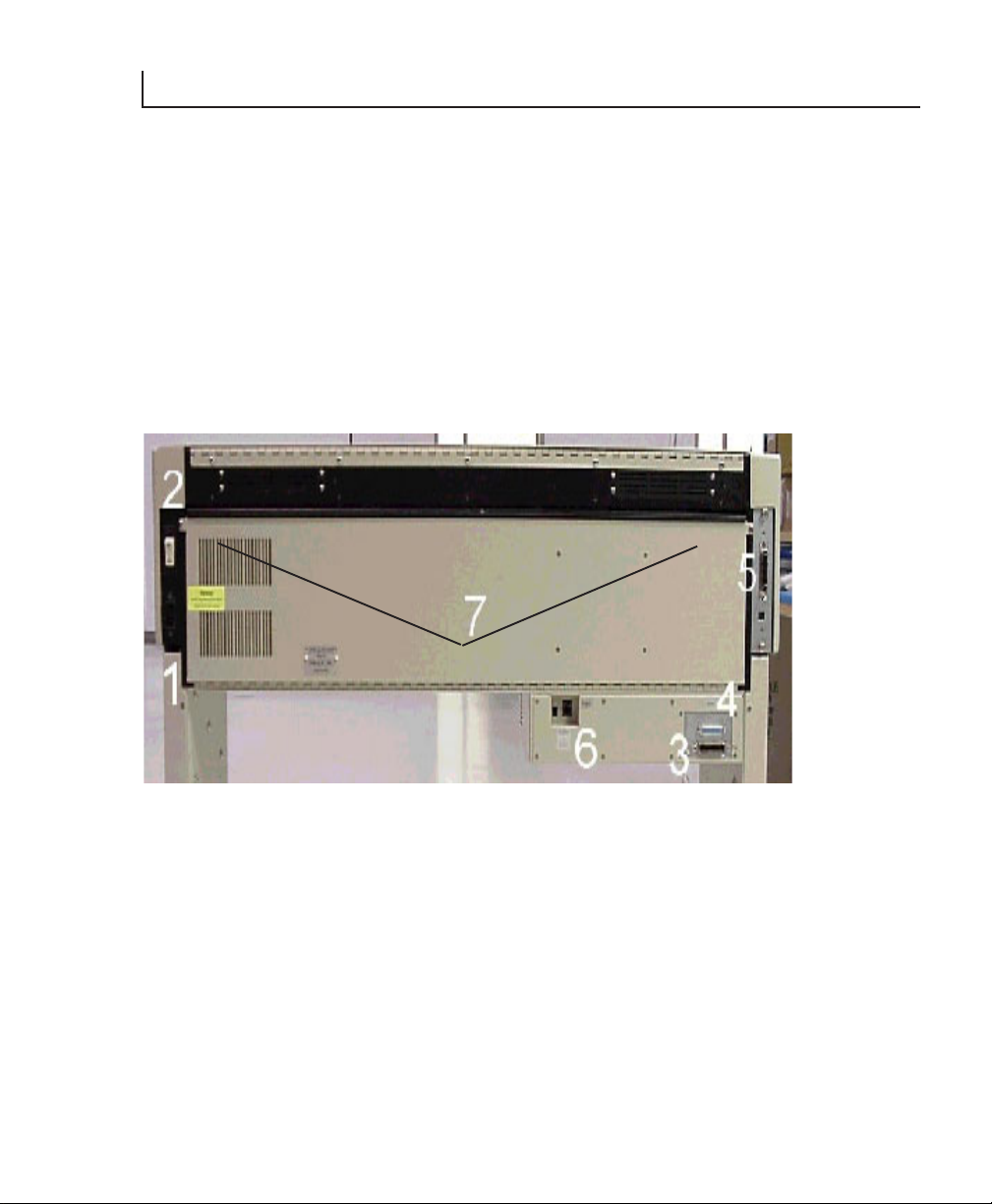
CABLE CONNECTIONS
The cable connections and power switch on the back of the i36 ImageMaster are
shown in Figure 1. They are:
1. AC power input.
2. Power (I/O) Switch.
3. PC/RIP Input (Centronics 36 pin).
4. PC/RIP Output (Centronics 25 pin).
5. Imager Input (Centronics 36 pin).
6. Network Input Port (with optional Internal Network Interface only).
NOTE: Also shown in Figure 1 are the two screws (7) securing the hinged back cover.
Figure 1. Back view of connections
The following instructions will allow you to properly connect the plotter.
AC Power Cable - 110/120 Volt
Plug the supplied AC power cable into the power connector (1).
Plug the other end of the power cord into a grounded AC outlet only.
NOTE: Avoid sharing a power outlet with noise-generating equipment.
8 i36 ImageMaster User Guide
Page 8

AC Power Cable - 220/230 Volt
CAUTION: Read the following procedure before connecting to a 220/230 volt
power source. The i36 ImageMaster power supply is not auto-switching.
Improper connection to a 220/230 volt power source will cause sever damage
to the PC/RIP and plotter.
CAUTION: The electronic components of the i36 ImageMaster can be
damaged by electrostatic discharge (ESD). To avoid ESD, maintain contact
with a ground source. A grounded wrist strap or similar device should be used.
WARNING: Electric shock warning.
NOTE: An optional 220/230 volt power cable is required for this procedure. Contact
iSys technical support for more information.
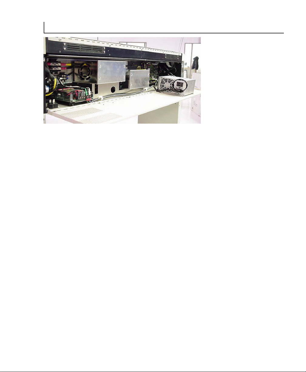
1. Remove the two screws in Figure 1 (7).
2. Locate the switches on the back of the power supply (see Figure 2).
3. Set the switch to 220/230 V.
4. Close hinged cover and replace screws.
3
i36 ImageMaster User Guide
9
Page 9
3
Figure 2. Power Supply
Connecting to your PC
1. Connect the 3 ft. Centronics cable (provided) to connectors 4 and 5 in Figure 1.
2. Connect your Centronics cable from your PC to connector 3 in Figure 1.
Connecting to your Network ( with optional Internal Network Interface)
1. Connect the 3 ft. Centronics cable (provided) to connectors 4 and 5 in figure 1.
2. Connect your network cable to connector 6 in Figure 1. A green indicator light on
the network port will light when connected.
NOTE: The manual and installation software for the optional Internal Network
Interface specified in your order are included with your shipment. You will have to
reset the IP address for the ImageMaster to be recognized by your network.
The following are the iSys factory settings for the optional Internal Network Interface:
- IP address: 90.0.0.1
- Subnet Mask: 255.255.255.0
- Gateway: 90.0.0.1
Connecting to your Network (with your external network interface)
NOTE: Follow the instructions provided by the manufacturer of your network
interface for installation and connection to your network.
1. Connect the 3 ft. Centronics cable (provided) to connectors 4 and 5 in Figure 1.
2. Connect your network interface to connector 3 in Figure 1.
10 i36 ImageMaster User Guide
Page 10
INSTALLING THE PRINT DRIVER
Spicer Docu-Jet Install Steps
The following screen shots are from Windows 2000. These screens will differ
depending on the operating system installed on the host machine. Some operating
systems require system administrators or a person with administrative privileges to
assist with installation of new printers. Should further assistance be required, contact
the iSys technical support team.
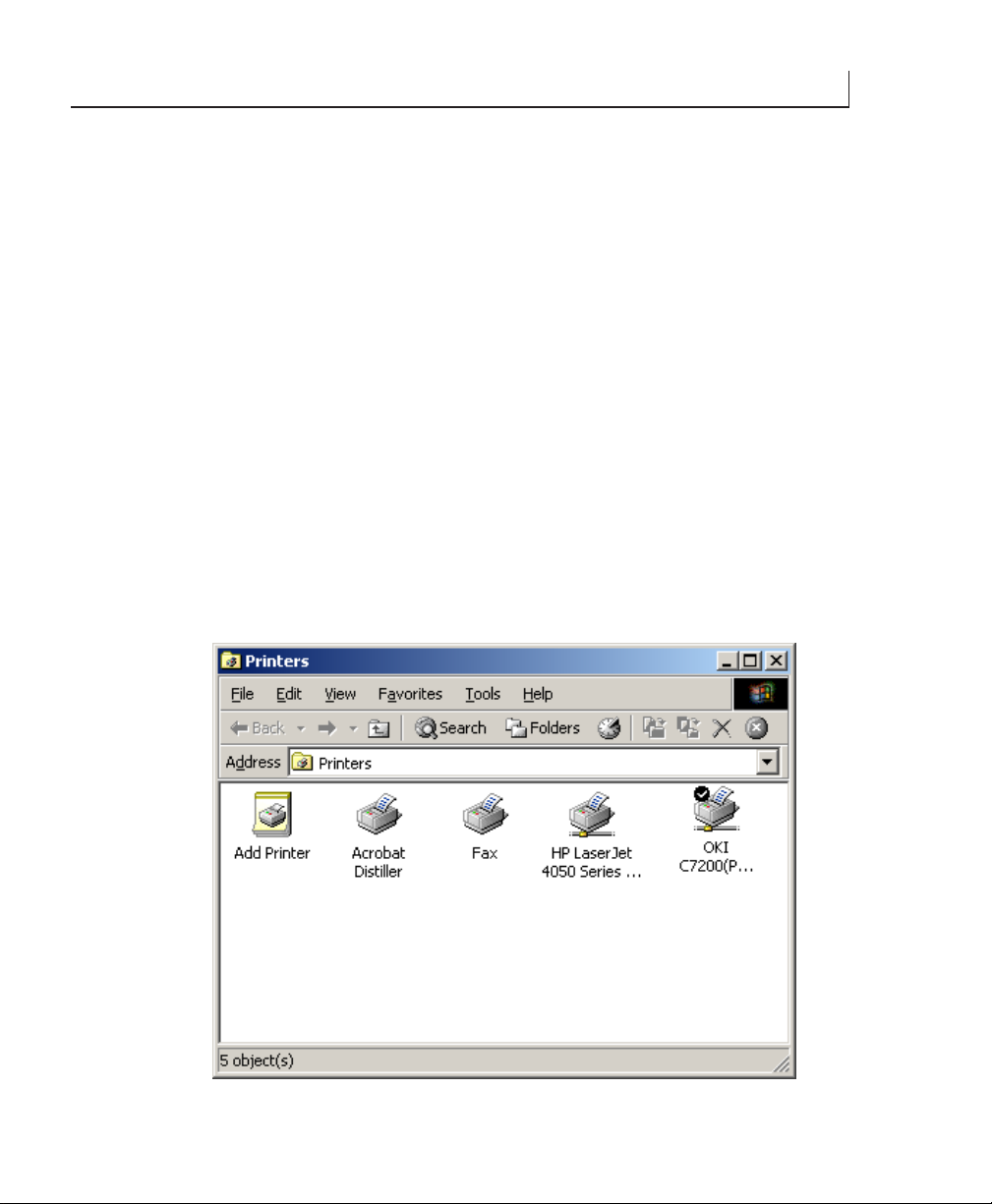
When receiving the demo driver in ZIP format, unzip the file to a familiar directory
(eg. c:\Temp). Then select start, Settings, Printers, Add printer.
1. When prompted for the driver, select “Have Disk” and follow through the
remaining prompts. If the installation is from a disk supplied from iSys, insert disk
into A:\ and select A:\ when asked.
2. Follow the prompts through the remaining steps. After the printer is added, you
will be prompted to register (see Figure 13).
3. Go into the properties of the New “docu-jet” printer and confirm the selections.
NOTE: The selections, resolution (Figure 11) and Output Format (Figure 12), are
required changes.
4
Figure 3.
i36 ImageMaster User Guide
11
Page 11

4
Figure 4.
Figure 5.
12 i36 ImageMaster User Guide
Page 12

Figure 6.
4
Figure 7.
i36 ImageMaster User Guide
13
Page 13

4
Figure 8.
Figure 9.
14 i36 ImageMaster User Guide
Page 14

The appropriate port for TCP/IP printing can be selected here if Jet admin has
already been setup for the i36.
Figure 10.
4
Figure 11.
i36 ImageMaster User Guide
15
Page 15

4
Figure 12
If HP jet admin is installed make sure the correct Port is selected. It should reflect the
port name given to the TCP/IP Port.
Figure 13
16 i36 ImageMaster User Guide
Page 16

You can enter any company name. The two important pieces of information that
must be exact are the serial number and the registration code (from the label on the
diskette). If this is for demo purposes, select “Register as Eval”.
Data Formats
The i36 ImageMaster is controlled by a PC running Windows 2000 and proprietary
iSys software (PC-RIP) which processes various file formats, including:
- CalComp 906/907/PCI
- CCGL
- CCRF
- CALS G4
- HP-GL
- HP-GL/2
- TIFF
- PS (option)
NOTE: Periodic changes, modifications or upgrades to the PC/RIP will be provided
to you by iSys.
4
i36 ImageMaster User Guide
17
Page 17
5
QUICKDRAW MEDIA INSTALLATION
CAUTION: Do not touch the thermal print head. Natural body oils can
damage the print head. Scratches in the print head will affect image quality.
Print head damage caused by users is not covered by warranty.
Your plotter comes with a sample roll of media properly installed. To replace or
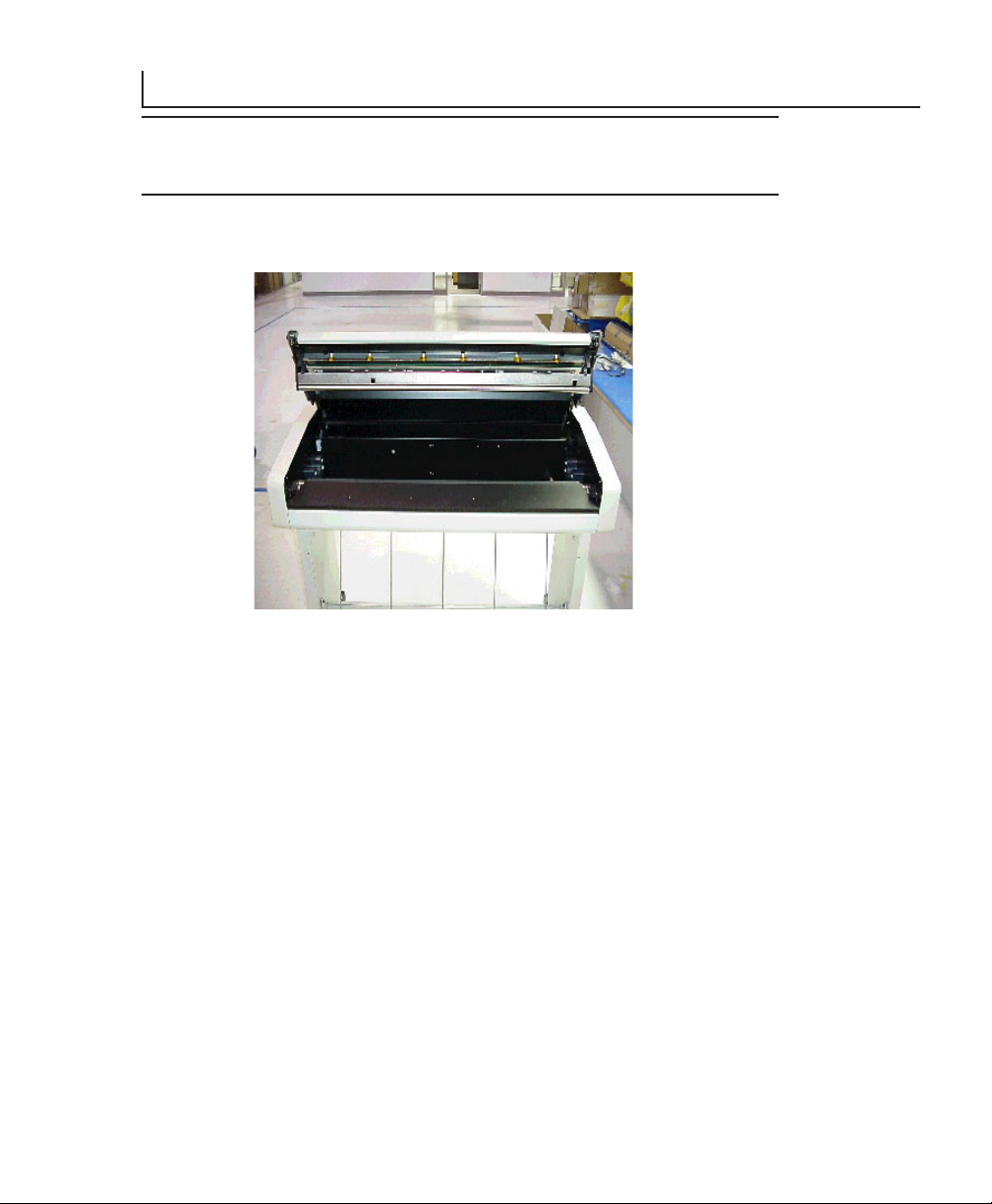
change media, refer to Figure 14 and the following procedure.
Figure 14. View of plotter with open lid.
NOTE: To open the plotter lid assembly, press down on one corner of the lid
assembly and pull the latch lever out and up. Repeat this process on the opposite side
of the lid assembly. Once the lid latches are open, the lid assembly will open with
light upward pressure.
Please Note:
1. A spindle or hub is inserted into each end of the media roll. The roll
ends are flush with the spindles or hubs.
2. The spindles or hubs are mounted in the spindle blocks, located on either
side ofthe media housing.
3. The media unwinds from the bottom of the install roll.
4. The media is threaded over the platen roller and under the black cutter
assembly bar. Figure 15 shows the proper threading sequence and media
path.
18 i36 ImageMaster User Guide
Page 18

Figure 15. Media Path.
To install a replacement media roll, open lid assembly as described on page 18
1. Replace media core and spindles from the spindle blocks by pulling the core up and
out through the lid opening.
5
2. Remove the spindles/hubs from both ends of the media core.
3. Insert spindles/hubs in the core ends of the new media roll.
4. Carefully position the new roll in the media housing and seat the spindles/hubs in
the spindle blocks. Press down firmly to seat the roll in the blocks. Ensure the roll
is seated squarely in the blocks.
5. Clean the print head with the Print Head Cleaning Pen.
CAUTION: The thermal print head should only be cleaned with the print head
cleaning pen or with a solution of 99.9% Isopropyl alcohol on a lint free wipe.
Water and other solvents can damage the print head. Print Head damage
caused by users is not covered by warranty.
i36 ImageMaster User Guide
19
Page 19

5
6. Thread the media as shown in figure 15. Allow an extra few inches of media
through the exit path, past the cutter assembly.
7. Once the media is through the exit path, hold the opposite sides of the media and
tug forward to squarely align and remove wrinkles.
8. Ensure that the lid latches are in the “open” position.
9. Hold the media taut with one hand and push the lid assembly down to the closed
position with the other hand.
10. Close and seat the lid latches by pressing down on one corner and pushing the
latch lever down and in. Repeat this preocess on the opposite side of the lid
assembly.
NOTE: If the lid latches are not properly seated, the red error light will display on the
Control Panel and “Latches Open” will appear in the LCD display.
11. Set control panel to “ON LINE” (see section 8 for information).
NOTE: Ensure media type shown in the LCD display corresponds with the actual
installed media. (Refer to section 8 if changes to settings are required).
CAUTION: The imaging characteristics of approved media are matched to
the thermal output of the print head. Operating at incorrect media settings or
with unapproved media may damage the print head. Print head damage caused
by such use is not covered by warranty.
20 i36 ImageMaster User Guide
Page 20

QUICKDRAW MEDIA FOR THE IMAGEMASTER
The iSys QuickDraw line of direct image media is matched to the performance
characteristics of our plotters to give you consistent, high quality results at an
economical price. Qualified QuickDraw papers and films are an essential part of the
imaging system that help to assure peak performance and long, trouble-free imager
life.
Premium Paper
A premium, heavy-weight paper that has the look and feel of bond paper. The highsensitivity imaging layer and bright white background produce sharp, crisp, fine-line
detail and dense solids. It features a protective top coat that resists water, scratching,
scuffing and marring. It is ideally suited for plots requiring frequent handling.
Report Paper
This medium-weight, high-sensitivity paper has a bright white background to
produce high-contrast output with crisp fine-line detail and dense solid fills. Report is
an economical choice for your high-volume, general-purpose output needs.
Rag Vellum
QuickDraw high-image-density transparent vellum is designed to meet your reproduction needs in most diazo applications. It features a scuff-resistant top coat for easy
handling when making multiple copies.
6
Clear Film
QuickSilver clear film provides high-density images on a 4 mil clear polyester base for
maximum light transmission and dimensional stability. Because the image is formed
from heat-activated silver, it has excellent UV light blocking capability, like photographic film. It’s waterproof top coat makes it extremely durable, with excellent
archival properties.
Cleaning Pens
The convenient cleaning pen assures proper print head maintenance, helps enhance
print quality and prolongs printhead life.
NOTE: For pricing and delivery on qualified QuickDraw media, please contact your
iSys sales representative or authorized dealer or visit our website at http://www.isysgroup.com
i36 ImageMaster User Guide
21
Page 21

7
STARTING THE I36 IMAGEMASTER
Plotter
To start the plotter, press the main power (I/O) Switch (see Figure 1 (2)). The plotter
will go through the startup sequence, beginning with the warmup phase, which
brings the unit to it’s operating temperature.
NOTE: During the warming phase, “Status: Warning XX” will appear in the LCD
display, indicating the approximate minutes remaining in the warming cycle.
PC/RIP
The PC/RIP will initialize (boot up) when the plotter power is turned on. Initializing
takes approximately 2-3 minutes, and occurs while the plotter is “warming”. The four
LEDs on the front panel of the PC/RIP indicate the status of the PC/RIP (see
Figure 16).
Green LED - Power
Red LED - Rip Processing
Green LED - PC/RIP initialized and ready
Yellow LED - Data transmission
Figure 16. PC/RIP LED Panel
22 i36 ImageMaster User Guide
Page 22

During the initializing procedure, the status of these LEDs is as follows:
1. The top green LED will remain lighted, indicating that the power is on.
2. The red LED will flash periodically, indicating that the PC/RIP is
initializing and Windows is opening. During normal operations, the red
will flash, indicating that the PC/RIP is processing a file from the host.
3. The lower green LED will light when the initializing process is
completed, indicating that the PC/RIP is ready to accept data from the
host.
4. The yellow LED indicates incoming data to the PC/RIP. During normal
operations, this light will flash when data files are being transmitted from
the host to the PC/RIP.
Accepting Plot Data
After the plotter and the PC/RIP have completed the startup procedures, the LCD
display will indicate “Status: RIP IDLE” and both green LEDs on the PC/RIP will
be on. The i36 ImageMaster is ready to receive data from the host. Data/plot files
transferred from the host to the PC/RIP are processed and transmitted to the print
engine for imaging.
7
i36 ImageMaster User Guide
23
Page 23

8
USING THE CONTROL PANEL AND LCD DISPLAY
The control panel of the i36 ImageMaster consists of an LCD display, three indicator
lights and six keys, as illustrated in Figure 17. It allows users to check plotter operating status and operating settings. It also provides warning/error messages and
feedback to the operator. Plotter settings and operating conditions can be changed
through the control panel.
Figure 17. Control Panel
The indicator lights show status as follows:
ON LINE Green when plotter is online and ready.
ERROR Red when a condition stops the plotter.
DATA Yellow when data is coming to the imager.
Key functions are identified as follows: ( in ON LINE/OFF LINE/ CHANGE
modes)
ON LINE/ OFF LINE/-
ABORT JOB/ CUT MEDIA/ SCROLL UP
-/FORM FEED/-
-/-/SCROLL DOWN
-/ MANUAL ADVANCE/ TOGGLE ITEM - SAVE
-/ NEXT SCREEN/-
24 i36 ImageMaster User Guide
Page 24

Settings changes can only be performed in the “OFF LINE” mode.
1. Take the plotter OFFLINE by pressing the ON/OFF LINE key. The green
ONLINE indicator light will turn off.
2. Find the desired menu or item by pressing the NEXT SCREEN key until that
menu appears in the LCD display.
3. SELECT UP/DOWN to move the display arrow to the item to be changed.
4. To change a setting, the display arrow must flash. Press the TOGGLE ITEM/
MANUAL ADVANCE key to make the display arrow flash, indicating the selected
item can be changed.
5. SELECT UP/DOWN to display the possible changes to the item selected. Stop at
the desired setting.
6. To save the change, the flashing display arrow must be turned off. Press the
TOGGLE ITEM/MANUAL ADVANCE key to stop the flashing and save the
change.
If additional changes are desired, repeat steps 2-6 until all changes are made. Return
to ONLINE mode.
8
Menu Selections
Menu Select Accesses user modes and function menus.
ARROW UP (media) or
ARROW DOWN
(test plot)
TOGGLE ITEM/
MANUAL ADVANCE
NOTE: An item is selectable when an arrow is displayed, and changeable when the
arrow is flashing. You can move to another menu item only if there is one or more
equal (=) signs elsewhere onthe screen.
i36 ImageMaster User Guide
Scrolling is from first to last only.
Moves the arrow up or down to the item that
you wish to change. When an item is selected,
pressing up/down arrow button changes to
the selection
Selects or deselects item to be changed. Deselecting
saves changes
25
Page 25

8
Holding the up or down arrow key while a menu item is selected will scroll through
the item options until a menu limit has been reached or the arrow key released. To
run a test plot:
1. Press ON/OFF LINE.
2. Press NEXT SCREEN until you reach the test plot screen.
3. Scroll down using down arrow key.
4. Press manual advance to select item.
5. Press up arrow key to change from NO to YES.
The plot will begin after about 3 seconds and will automatically change the menu
item from YES back to NO once the plot is finished.
Functions and Settings
Control panel settings are saved as presets for either USER M1 or USER M2. Presets
are initially set to defaults for all menu functions.
Changes to function settings are stored upon pressing TOGGLE ITEM/MANUAL
ADVANCE. Changes are retained even while the main power is switched to off.
To restore the default settings for both USER modes, turn the power switch on
while pressing down the NEXT SCREEN button.
26 i36 ImageMaster User Guide
Page 26

User Mode
Selects between two user-defined settings. To access functions in
either user mode.
- select ON/OFF LINE.
- press MENU button until user mode is displayed.
- press MANUAL ADVANCE to select (arrow will flash)
- press up arrow
To deselect an item, press MANUAL ADVANCE again.
Speed
Adjusts the speed of the plot output. The default is low. Change the speed by
selecting the speed option in the appropriate menu. Move up or down the scale by
pressing the up and down arrows. Deselecting will save changes.
NOTE: If the plot speed is erratic, or if output quality is unacceptable, lower the plot
speed. Such problems may arise when data enters the plotter at a slower rate than the
plotter is set for. This is most likely to occur on the MAX setting. Lowering the plot
speen enables the plotter to match the input rate of data and produces a smoother,
better quality output.
8
When the media setting is FILM, the plotter adjusts the speed for maximum quality
printing at 1/4 inch/second.
Media
Selects supported media types. The default setting is “No Top Coat Paper”, displayed
as “NOT.C.P”. Note that if you use other media, you must adjust the media setting.
If unsure of the media specifications, start at the NOT.C.P setting and then increase
the setting to T.C.PAPER if necessary.
Change the media by pressing the up or down arrows in the MEDIA submenu.
Select NOT.C.P (light paper), TC PAPER (heavy paper), VELLUM, or FILM. Note
that in the FILM mode the print head’s normal setting for contratst is raised.
i36 ImageMaster User Guide
27
Page 27

8
This requires a slower plot speed (see Speed section of guide). Do not use the FILM
setting on any other media other than film.
CAUTION: Thermal plotting technology involves high temperatures,
incorrect media settings can damage the print head or other components.
Damage caused by users is not covered by warranty.
Test Plot
Generates a test plot. Six inches of plot are produced in a checkerboard pattern so you
can see if the plotter is creating a plot image and feeding the paper correctly, and if
contrast levels and media settings are acceptable.
To change from the default TEST PLOT setting of NO, press the up button in the
TEST PLOT submenu to display YES, then press the MANUAL ADVANCE
button to enable the test.
NOTE: Plot creation takes about 2-3 seconds before plotting.
Beeper
Controls the audible signal for error messages such as media out warning. This
sound can be changed to SOLIDTONE, TONE FOR ONE MINUTE, FAST
PULSE, 3 SECONDS, FIVE TIMES, or OFF.
Scaling
Use scaling to compensate plot length measurement for tolerances in media thickness,
roller diameter and head pressure. The amount of change is up to +/- 120/64 in. to
+/- 1.875 in. of plot. the default setting is 0.
Change the scaling setting by pressing the up or down buttons in the SCALING
submenu. The up button accesses positive (stretch) increments from 3/64 in. to 120/
64 in. (1.875 in.).
FF Length
Adjusts the length of media moved (in inches) if a manual form-feed, remote formfeed, or an end of transmission (EOT) is detected. The maximum adjustment is 99
in. The default setting is 5 in.
28 i36 ImageMaster User Guide
Page 28

End of Transmission (EOT) Cut
If enabled, makes the plotter cut the media after it detects a remote end of transmission.
Shutdown RIP
Safely shuts down the RIP portion of the plotter, maintaining file integrity, and
allowing the RIP box to be more reliable.
When the plotter is taken OFFLINE the first menu screen includes the shutdown
RIP option. If this menu is set to YES, communication between the plotter and the
RIP box will be attempted.
No communication is available while the RIP box is transferring data tot he plotter.
If the plotter detects a job being input or is presently plotting, it will immediately
stop plotting and dump any further unwanted data received from the RIP.
After communication is re-established, the plotter will be idle for approxiamtely four
seconds and then display the following message on the front display:
8
RIP HAS SHUTDOWN. IT IS NOW SAFE TO POWER
OFF THE I36 PLOTTER.
i36 ImageMaster User Guide
29
Page 29

9
WARRANTY, MAINTENANCE AND SERVICE
Warranty
The iSys written warranty is included with your shipment. Please take the time to read
the warranty so you fully understand your coverage under its provisions. As the
owner of the i36 ImageMaster, you will be able to take advantage of technical
support during the warranty period and receive notification of new features, upgrades, documentation and accessories.
Maintenance
The i36 ImageMaster requires little routine maintenance. Recommended maintenance
will enhance performance, extend useful life and can be performed quickly and easily at
the installed location.
1. Use 99% Isopropyl alcohol to clean the print head.
2. Check that shocks on the lid assembly are functioning correctly.
Service Call
Toll Free: 1-866-415-4797 (iSys)
Phone: (403) 204-5212
Fax: (403) 204-1971
E-mail: support@isys-group.com
Sales Information
Toll Free: 1-866-415-4797
Phone: (403) 204-1977
Fax: (403) 204-1971
E-mail: sales@isys-group.com
Website: www.isys-group.com
30 i36 ImageMaster User Guide
Page 30

 Loading...