

Isuzu RODEO General Description Manual

RODEO
Brake Control System 5A–1. . . . . . . . . . . . . . . . . . . .
Anti–lock Brake System 5B–1. . . . . . . . . . . . . . . . . .
Power–assisted Brake System 5C–1. . . . . . . . . . . .
Parking Brakes (4x4 Model) 5D1–1. . . . . . . . . . . . . .
Parking Brakes (4x2 Model) 5D2–1. . . . . . . . . . . . . .
Brake Control System
BRAKES
CONTENTS
CONTENTS
BRAKE CONTROL SYSTEM
5A–1
Service Precaution 5A–2. . . . . . . . . . . . . . . . . . . . . .
General Description 5A–3. . . . . . . . . . . . . . . . . . . . .
Functional Description 5A–4. . . . . . . . . . . . . . . . .
System Components 5A–10. . . . . . . . . . . . . . . . . . .
Electronic Hydraulic Control Unit (EHCU) 5A–10.
ABS Warning Light 5A–10. . . . . . . . . . . . . . . . . . . .
Wheel Speed Sensor 5A–10. . . . . . . . . . . . . . . . . .
G-Sensor 5A–10. . . . . . . . . . . . . . . . . . . . . . . . . . . . .
Normal and Anti-lock Braking 5A–10. . . . . . . . . . .
Brake Pedal Travel 5A–10. . . . . . . . . . . . . . . . . . . .
Acronyms and Abbreviations 5A–10. . . . . . . . . . . .
General Diagnosis 5A–11. . . . . . . . . . . . . . . . . . . . . . .
General Information 5A–11. . . . . . . . . . . . . . . . . . . .
ABS Service Precautions 5A–11. . . . . . . . . . . . . . .
Computer System Service Precautions 5A–11. . .
General Service Precautions 5A–11. . . . . . . . . . . .
Note on Intermittents 5A–11. . . . . . . . . . . . . . . . . . .
Test Driving ABS Complaint Vehicles 5A–12. . . . .
“ABS” Warning Light 5A–12. . . . . . . . . . . . . . . . . . .
Normal Operation 5A–12. . . . . . . . . . . . . . . . . . . . .
Tech 2 Scan Tool 5A–13. . . . . . . . . . . . . . . . . . . . . .
DATA LIST 5A–16. . . . . . . . . . . . . . . . . . . . . . . . . . .
ACTUATOR TEST 5A–17. . . . . . . . . . . . . . . . . . . . .
Tech 2 Service Bleed 5A–21. . . . . . . . . . . . . . . . . .
Basic Diagnostic Flow Chart 5A–22. . . . . . . . . . . .
Basic Inspection Procedure 5A–23. . . . . . . . . . . . .
EHCU Connector Pin-out Checks 5A–24. . . . . . . . .
Circuit Diagram 5A–25. . . . . . . . . . . . . . . . . . . . . . .
Connector List 5A–28. . . . . . . . . . . . . . . . . . . . . . . .
Part Location 5A–29. . . . . . . . . . . . . . . . . . . . . . . . .
Symptom Diagnosis 5A–30. . . . . . . . . . . . . . . . . . . . .
Chart A-1 ABS Works Frequently But
Vehicle Does Not Decelerate 5A–30. . . . . . . . . . .
Chart T A-1 ABS Works Frequently But
Vehicle Does Not Decelerate
(Use TECH 2) 5A–31. . . . . . . . . . . . . . . . . . . . . . . .
Chart A-2 Uneven Braking Occurs While
ABS Works 5A–31. . . . . . . . . . . . . . . . . . . . . . . . . . .
Chart T A-2 Uneven Braking Occurs While
ABS Works (Use TECH 2) 5A–31. . . . . . . . . . . . .
Chart A-3, TA-3 The Wheels Are Locked 5A–32.
Chart A-4 Brake Pedal Feed Is Abnormal 5A–33.
Chart A-5, TA-5 Braking Sound
(From EHCU) Is Heard While Not Braking 5A–34
Diagnostic Trouble Codes 5A–35. . . . . . . . . . . . . . . .
Diagnosis By “ABS” Warning Light
Illumination Pattern 5A–37. . . . . . . . . . . . . . . . . . . . .
Diagnostic Trouble Codes (DTCs) 5A–38. . . . . . .
Chart B-1 With the key in the ON position
(Before starting the engine). Warning
light (W/L) is not activated. 5A–40. . . . . . . . . . . . .
Chart B-2 CPU Error (DTC 14 (Flash out) /
C0271, C0272, C0273, C0284 (Serial
communications)) 5A–41. . . . . . . . . . . . . . . . . . . . .
Chart B-3 Low or High Ignition Voltage
(DTC 15 (Flash out) / C0277, 0278
(Serial communications)) 5A–41. . . . . . . . . . . . . . .
Chart B-4 Excessive Dump Time
(DTC 17 (Flash out) / C0269
(Serial communications)) 5A–41. . . . . . . . . . . . . . .
Chart B-5 Excessive Isolation Time
(DTC 18 (Flash out) / C0274
(Serial communications)) 5A–42. . . . . . . . . . . . . . .
Chart B-6 G-Sensor Output Failure
(DTC 21 (Flash out) / C0276
(Serial communications)) 5A–42. . . . . . . . . . . . . . .
Chart B-7 Brake Switch Failure
(DTC 22 (Flash out) / C0281
(Serial communications)) 5A–42. . . . . . . . . . . . . . .
Chart B-8 2WD Controller in 4WD Vehicle
Controller (DTC 13 (Flash out) / C0285
(Serial communications)), 4WD State Input
Signal Failure (DTC 24 (Flash out) / C0282
(Serial communications)) 5A–43. . . . . . . . . . . . . . .
Chart B-9 Pump Motor Failure (DTC 32
(Flash out) / C0267, C0268
(Serial communications)) 5A–43. . . . . . . . . . . . . . .
Chart B-10 EHCU Valve Relay Failure
(DTC 35 (Flash out) / C0265, C0266
(Serial communications)) 5A–44. . . . . . . . . . . . . . .
Chart B-11 FL Isolation Solenoid Coil Failure
(DTC 41 (Flash out) / C0245, C0247
(Serial communications)) 5A–44. . . . . . . . . . . . . . .
Chart B-12 FL Dump Solenoid Coil Failure
(DTC 42 (Flash out) / C0246, C0248
(Serial communications)) 5A–44. . . . . . . . . . . . . . .

5A–2
BRAKE CONTROL SYSTEM
Chart B-13 FR Isolation Solenoid Coil Failure
(DTC 43 (Flash out) / C0241, C0243
(Serial communications)) 5A–45. . . . . . . . . . . . . . .
Chart B-14 FR Dump Solenoid Coil Failure
(DTC 44(Flash out) / C0242, C0244
(Serial communications)) 5A–45. . . . . . . . . . . . . . .
Chart B-15 Rear Isolation Solenoid Coil
Failure (DTC 45 (Flash out) / C0251,
C0253 (Serial communications)) 5A–45. . . . . . . .
Chart B-16 Rear Dump Solenoid Coil
Failure (DTC 46 (Flash out) / C0252,
C0254 (Serial communications)) 5A–46. . . . . . . .
Chart B-17 FL Speed Sensor Open or
Shorted (DTC 51 (Flash out) / C0225
(Serial communications)) 5A–46. . . . . . . . . . . . . . .
Chart B-18 FR Speed Sensor Open or
Shorted (DTC 52 (Flash out) / C0221
(Serial communications)) 5A–47. . . . . . . . . . . . . . .
Chart B-19 Rear Speed Sensor Open or
Shorted (DTC 53 (Flash out) / C0235
(Serial communications)) 5A–48. . . . . . . . . . . . . . .
Chart B-20 FL Speed Sensor Missing
(DTC 61 (Flash out) / C0226, C0227
(Serial communications)) 5A–49. . . . . . . . . . . . . . .
Service Precaution
WARNING: THIS VEHICLE HAS A SUPPLEMENTAL
RESTRAINT SYSTEM (SRS). REFER TO THE SRS
COMPONENT AND WIRING LOCATION VIEW IN
ORDER TO DETERMINE WHETHER YOU ARE
PERFORMING SERVICE ON OR NEAR THE SRS
COMPONENTS OR THE SRS WIRING. WHEN YOU
ARE PERFORMING SERVICE ON OR NEAR THE SRS
COMPONENTS OR THE SRS WIRING, REFER TO
THE SRS SERVICE INFORMATION. FAILURE TO
FOLLOW WARNINGS COULD RESULT IN POSSIBLE
AIR BAG DEPLOYMENT, PERSONAL INJURY, OR
OTHERWISE UNNEEDED SRS SYSTEM REPAIRS.
Chart B-21 FR Speed Sensor Missing
(DTC 62 (Flash out) / C0222, C0223
(Serial communications)) 5A–50. . . . . . . . . . . . . . .
Chart B-22 Rear Speed Sensor Missing
(DTC 63 (Flash out) / C0236, C0237
(Serial communications)) 5A–51. . . . . . . . . . . . . . .
Chart B-23 Simultaneous Drop-out of
Front Speed Sensor Signal (DTC 64 (Flash
out) / C0229 (Serial communications)) 5A–52. . .
Chart B-24 Wheel Speed Input Abnormality
(DTC 65 (Flash out) / C0238 (Serial
communications)) 5A–53. . . . . . . . . . . . . . . . . . . . .
Unit Inspection Procedure 5A–54. . . . . . . . . . . . . . . .
Chart C-1-1 FL Sensor Output Inspection
Procedure 5A–54. . . . . . . . . . . . . . . . . . . . . . . . . . .
Chart C-1-2 FR Sensor Output Inspection
Procedure 5A–55. . . . . . . . . . . . . . . . . . . . . . . . . . .
Chart C-1-3 Rear Sensor Output Inspection
Procedure 5A–55. . . . . . . . . . . . . . . . . . . . . . . . . . .
Chart TC-1 Sensor Output Inspection
Procedure 5A–56. . . . . . . . . . . . . . . . . . . . . . . . . . .
Special Tools 5A–57. . . . . . . . . . . . . . . . . . . . . . . . . . .
CAUTION: Always use the correct fastener in the
proper location. When you replace a fastener, use
ONLY the exact part number for that application.
ISUZU will call out those fasteners that require a
replacement after removal. ISUZU will also call out
the fasteners that require thread lockers or thread
sealant. UNLESS OTHERWISE SPECIFIED, do not
use supplemental coatings (Paints, greases, or other
corrosion inhibitors) on threaded fasteners or
fastener joint interfaces. Generally, such coatings
adversely affect the fastener torque and the joint
clamping force, and may damage the fastener. When
you install fasteners, use the correct tightening
sequence and specifications. Following these
instructions can help you avoid damage to parts and
systems.

General Description
The Anti-lock Brake System (ABS) works on all four
wheels. A combination of wheel speed sensor and
Electronic Hydraulic Control Unit (EHCU) can determine
when a wheel is about to stop turning and adjust brake
pressure to maintain best braking.
BRAKE CONTROL SYSTEM
This system helps the driver maintain greater control of
the vehicle under heavy braking conditions.
NOTE: The Electronic Hydraulic Control Unit (EHCU)
comprises the Hydraulic Unit (H/U) and the coil Integrated
Module.
5A–3
Legend
(1) Electronic
(2) Hydraulic
(3) Hydraulic Unit (H/U)
C05RW004
(4) Coil Integrated Module
(5) Front Wheel Speed Sensor
(6) Rear Wheel Speed Sensor
(7) Proportioning and Bypass (P&B) Valve
5A–4
BRAKE CONTROL SYSTEM
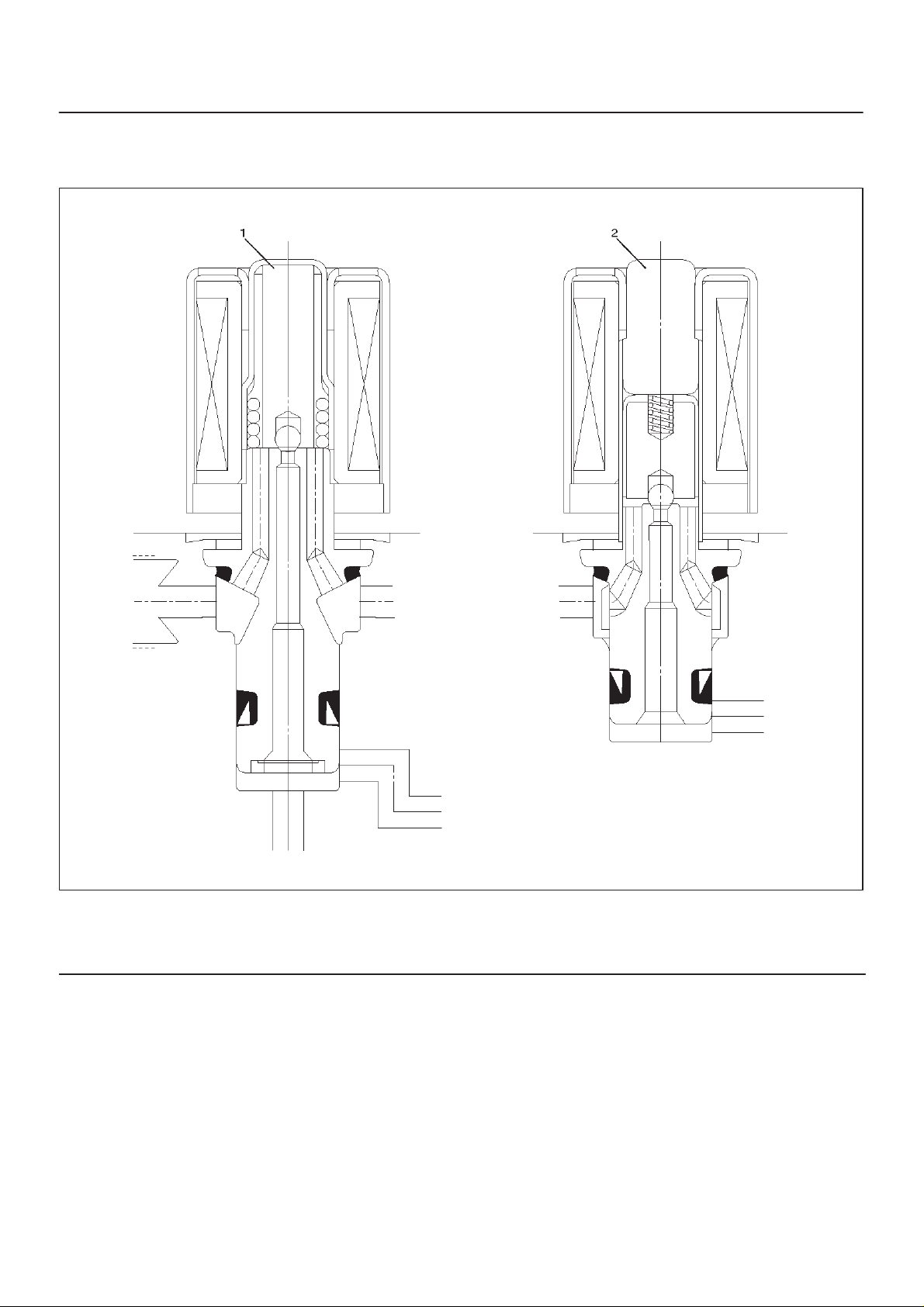
Functional Description
Hydraulic Unit (H/U)
Solenoid Valve
Legend
(1) Isolation Valve
(2) Dump valve
C05RW012
BRAKE CONTROL SYSTEM
5A–5
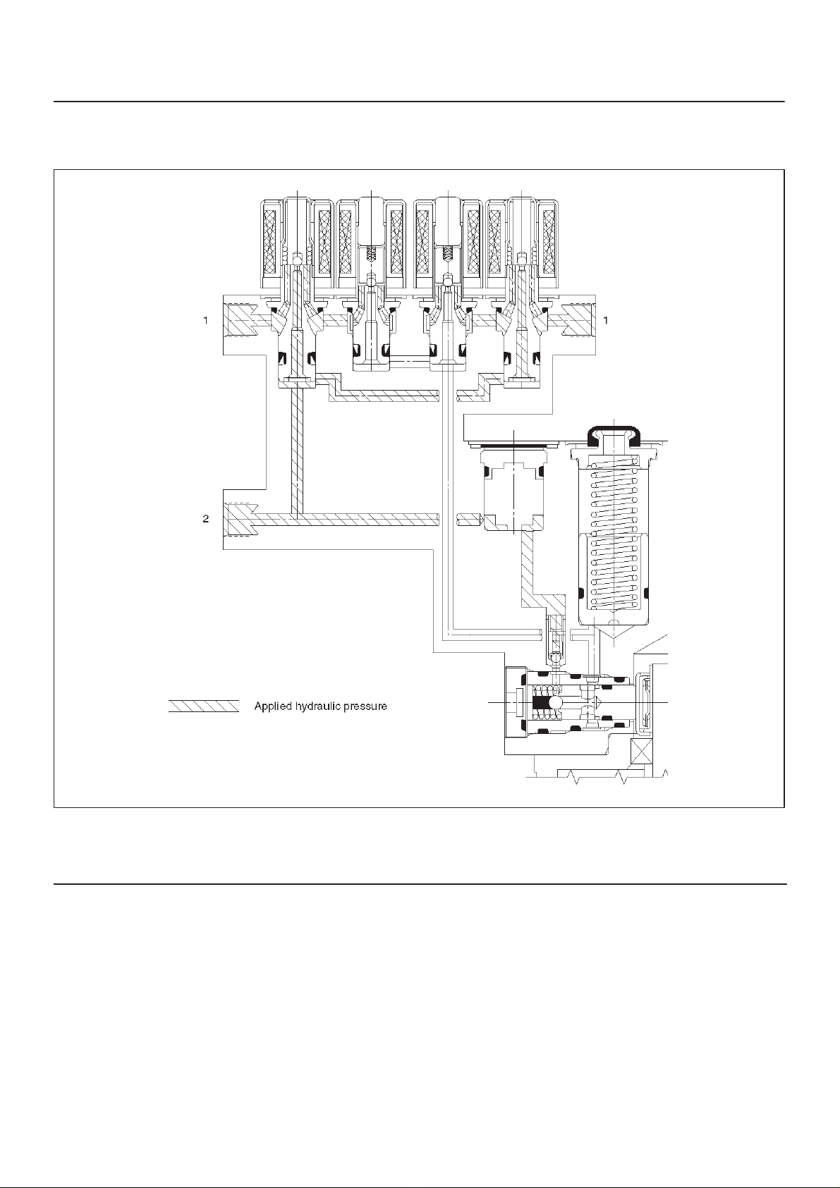
Normal Braking
During normal (non anti-lock) braking, the solenoid valves
are without current and closed due to spring force.
Brake fluid travels through the centre of the normally open
isolation valve around the normally closed dump valve
and on to the brake pistons.
Legend
(1) Brake
(2) Master Cylinder
C05RW010
5A–6
BRAKE CONTROL SYSTEM
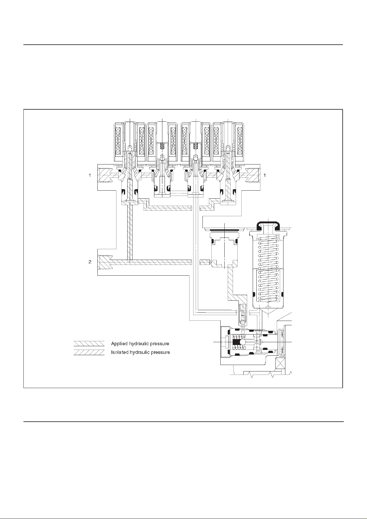
Pressure Isolation (Pressure Maintain)
The electro-hydraulic control unit is activated when the
brakes are applied which sends a signal to the coil
integrated module to prepare for a possible anti-lock stop.
If the information from the wheel speed sensors indicates
excessive wheel deceleration (imminent lockup), the first
step in the anti-lock sequence is to isolate the brake
pressure being applied by the brake pedal.
The microprocessor in the coil integrated module sends a
voltage to the coil to energize and close the isolation
valve. This prevents any additional fluid pressure applied
by the brake pedal from reaching the wheel. With the
isolation valves closed, further unnecessary increase in
the brake pressure is therefore prevented.
Legend
(1) Brake
(2) Master Cylinder
C05RW011
BRAKE CONTROL SYSTEM
5A–7
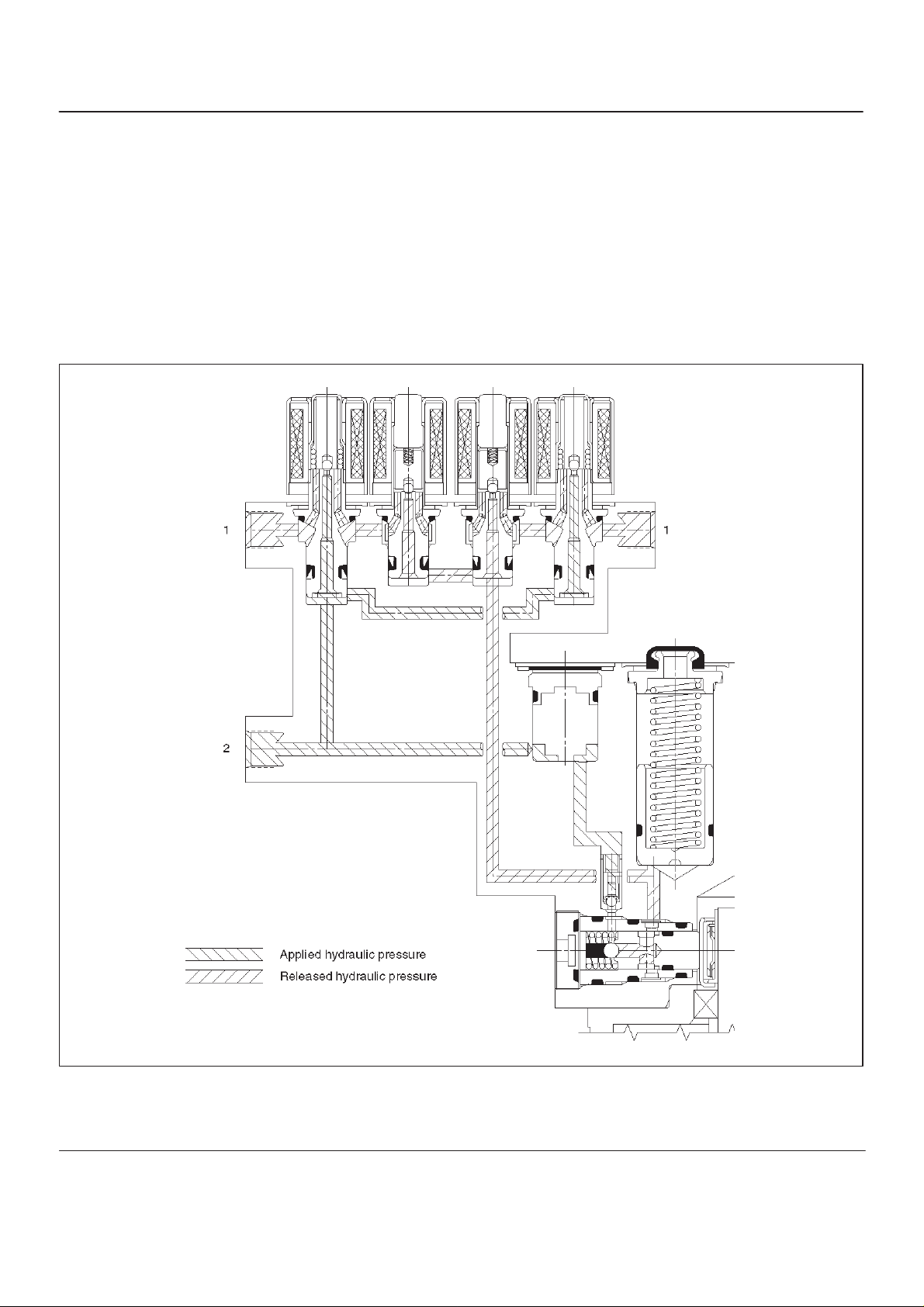
Pressure Reduction
Once the brake pressure is isolated, it must be reduced to
allow the wheels to unlock. This is accomplished by
dumping a portion of the brake fluid pressure into a low
pressure accumulator.
The microprocessor activates the normally closed dump
valve to open, allowing fluid from the wheels to be
dumped into the accumulator. This is done with very short
activation pulses opening and closing the dump valve
passageway . Brake pressure is reduced at the wheel and
allows the wheel to begin rotating again. The fluid from the
brake piston is stored in the accumulator against spring
pressure and a portion of this fluid also primes the pump.
The dump valves are operated independently to control
the deceleration of the wheel. At this point, the brake
pedal is isolated from the base brake system, the
hydraulic control unit pumps are primed and the
attenuators are ready to pump fluid.
Legend
(1) Brake
(2) Master Cylinder
C05RW009
5A–8
BRAKE CONTROL SYSTEM
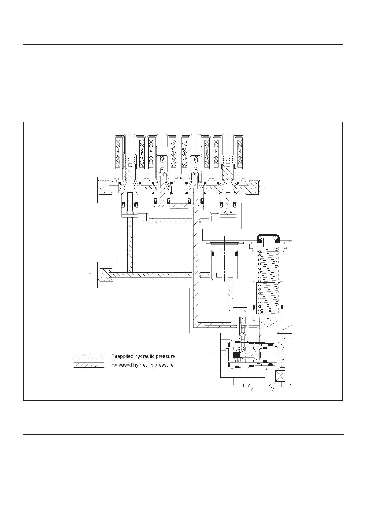
Pressure Increase (Re-apply)
The re-apply sequence is initiated to achieve optimum
braking. The isolation valve is momentarily opened to
allow master cylinder and pump pressure to reach the
brakes. This controlled pressure rise continues until the
wheel is at optimum brake output or until the brake
pressure is brought up to the master cylinder output
pressure.
If more pressure is required, more fluid is drawn from the
master cylinder and applied to the brakes. The driver may
feel slight pedal pulsations, or pedal drop, this is normal
and expected.
As fluid is re-applied to the brakes, the wheel speed will
reduce. If the wheels approach imminent lockup again,
the module will isolate, dump and re-apply again. This
cycle occurs in millisecond intervals, allowing several
cycles to occur each second. It is a much faster and more
controlled way of “pumping the pedal”.
Legend
(1) Brake
(2) Master Cylinder
C05RW014
BRAKE CONTROL SYSTEM
5A–9
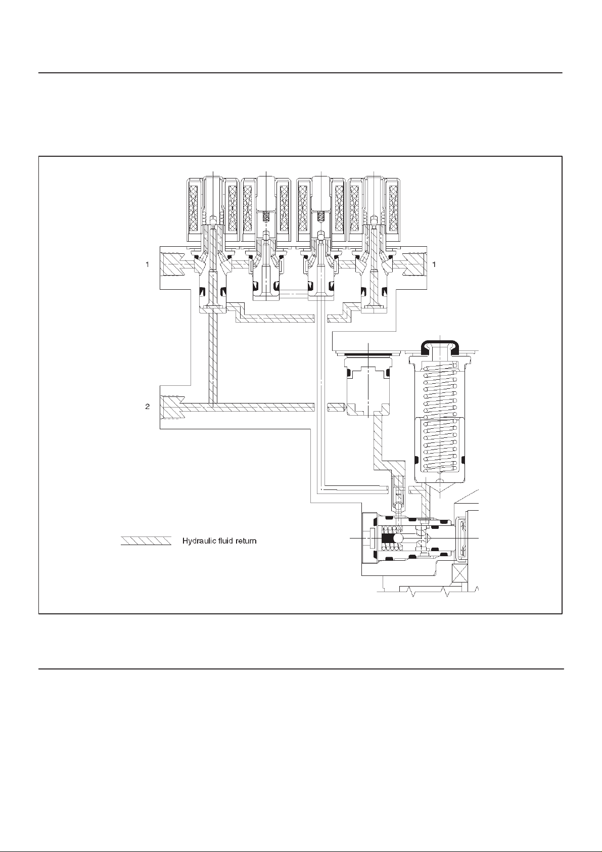
Brake Release
At the end of the anti-lock stop, when the brake pedal is
released, the pump will remain running for a short time to
help drain any fluid from the accumulators. As this fluid
returns into the system, the spring forces the piston back
to its original position.
The isolation valve opens and fluid may return to the
master cylinder. Conventional braking is then resumed.
Legend
(1) Brake
(2) Master Cylinder
C05RW013
5A–10
BRAKE CONTROL SYSTEM
System Components
Electronic Hydraulic Control Unit (EHCU), three Wheel
Speed Sensors, Warning Light, and G-sensor.
Electronic Hydraulic Control Unit (EHCU)
The EHCU consists of ABS control circuits, fault detector,
and a fail-safe. It drives the hydraulic unit according to the
signal from each sensor, cancelling ABS to return to
normal braking when a malfunction has occurred in the
ABS.
The EHCU has a self-diagnosing function which can
indicate faulty circuits during diagnosis.
The EHCU is mounted on the engine compartment rear
right side. It consists of a Motor, Plunger Pump, Solenoid
V alves.
Solenoid Valves: Reduces or holds the caliper fluid
pressure for each front disc brake or both rear disc brakes
according to the signal sent from the EHCU.
Reservoir: Temporarily holds the brake fluid that returns
from the front and rear disc brake caliper so that pressure
of front disc brake caliper can be reduced smoothly.
Plunger Pump: Feeds the brake fluid held in the reservoir
to the master cylinder.
Motor: Drives the pump according to the signal from
EHCU.
Check Valve: Controls the brake fluid flow.
ABS Warning Light
Wheel Speed Sensor
It consists of a sensor and a rotor. The sensor is attached
to the knuckle on the front wheels and to the rear axle
case on the rear differential.
The rotor is press-fit in the axle shaft.
The flux generated from electrodes magnetized by a
magnet in the sensor varies due to rotation of the rotor,
and the electromagnetic induction generates alternating
voltage in the coil. This voltage draws a “sine curve” with
the frequency proportional to rotor speed and it allows
detection of wheel speed.
G-Sensor
The G-sensor installed inside the EHCU detects the
vehicle deceleration speed and sends a signal to the
EHCU. In 4WD operation, all four wheels may be
decelerated in almost the same phase, since all wheels
are connected mechanically.
This tendency is noticeable particularly on roads with low
friction coefficient, and the ABS control is adversely
affected.
The G-sensor judges whether the friction coefficient of
road surface is low or high, and changes the EHCU’s
operating system to ensure ABS control.
Normal and Anti-lock Braking
Under normal driving conditions, the Anti-lock Brake
System functions the same as a standard power assisted
brake system. However, with the detection of wheel
lock-up, a slight bump or kick-back will be felt in the brake
pedal. This pedal “bump” will be followed by a series of
short pedal pulsations which occurs in rapid succession.
The brake pedal pulsation will continue until there is no
longer a need for the anti-lock function or until the vehicle
is stopped. A slight ticking or popping noise may be heard
during brake applications when the Anti-lock features is
being used.
When the Anti-lock feature is being used, the brake pedal
may rise even as the brakes are being applied. This is
also normal. Maintaining a constant force on the pedal
will provide the shortest stopping distance.
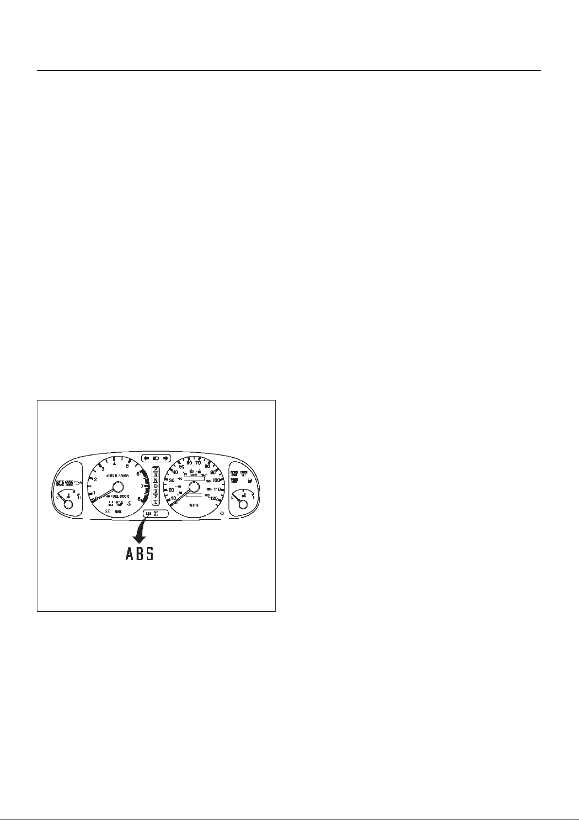
Vehicles equipped with the Anti-lock Brake System have
821RW093
an amber “ABS” warning light in the instrument panel.
The “ABS” warning light will illuminate if a malfunction in
the Anti-lock Brake System is detected by the Electronic
Hydraulic Control Unit (EHCU). In case of an electronic
malfunction, the EHCU will turn “ON” the “ABS” warning
light and disable the Anti-lock braking function.
The “ABS” light will turn “ON” for approximately three
seconds after the ignition switch is to the “ON” position.
If the “ABS” light stays “ON” after the ignition switch is the
“ON” position, or comes “ON” and stays “ON” while
driving, the Anti-lock Brake System should be inspected
for a malfunction according to the diagnosis procedure.
Brake Pedal Travel
Vehicles equipped with the Anti-lock Brake System may
be stopped by applying normal force to the brake pedal.
Although there is no need to push the pedal beyond the
point where it stops or holds the vehicle, by applying more
force the pedal will continue to travel toward the floor.
This extra brake pedal travel is normal.
Acronyms and Abbreviations
Several acronyms and abbreviations are commonly used
throughout this section:
ABS
Anti-lock Brake System
CIM
Coil Integrated Module
CKT
Circuit

BRAKE CONTROL SYSTEM
5A–11
DLC
Data Link Connector
EHCU
Electronic Hydraulic Control Unit
FL
Front Left
FR
Front Right
GEN
Generator
H/U
Hydraulic Unit
MV
Millivolts
RR
Rear
RPS
Revolution per Second
VDC
DC Volts
VAC
AC Volts
W/L
Warning Light
WSS
Wheel Speed Sensor
General Diagnosis
General Information
ABS troubles can be classified into two types, those
which can be detected by the ABS warning light and those
which can be detected as a vehicle abnormality by the
driver.
In either case, locate the fault in accordance with the
“BASIC DIAGNOSTIC FLOWCHART” and repair.
Please refer to Section 5C for the diagnosis of
mechanical troubles such as brake noise, brake judder
(brake pedal or vehicle vibration felt when braking),
uneven braking, and parking brake trouble.
Powertrain Control Module. These modules are designed
to withstand normal current draws associated with
vehicle operation. However, care must be taken to avoid
overloading any of the EHCU circuits. In testing for opens
or shorts, do not ground or apply voltage to any of the
circuits unless instructed to do so by the appropriate
diagnostic procedure. These circuits should only be
tested with a high impedance multimeter (J-39200) or
special tools as described in this section. Power should
never be removed or applied to any control module with
the ignition in the “ON” position.
Before removing or connecting battery cables, fuses or
connectors, always turn the ignition switch to the “OFF”
position.
General Service Precautions
The following are general precautions which should be
observed when servicing and diagnosing the Anti-lock
Brake System and/or other vehicle systems. Failure to
observe these precautions may result in Anti-lock Brake
System damage.
D If welding work is to be performed on the vehicle using
an electric arc welder, the EHCU and valve block
connectors should be disconnected before the
welding operation begins.
D The EHCU and valve block connectors should never
be connected or disconnected with the ignition “ON” .
D If only rear wheels are rotated using jacks or drum
tester, the system will diagnose a speed sensor
malfunction and the “ABS” warning light will
illuminate. But actually no trouble exists. After
inspection stop the engine once and re-start it, then
make sure that the “ABS” warning light does not
illuminate.
If the battery has been discharged
The engine may stall if the battery has been completely
discharged and the engine is started via jumper cables.
This is because the Anti-lock Brake System (ABS)
requires a large quantity of electricity. In this case, wait
until the battery is recharged, or set the ABS to a
non-operative state by removing the fuse for the ABS
(60A). After the battery has been recharged, stop the
engine and install the ABS fuse. Start the engine again,
and confirm that the ABS warning light does not light.
ABS Service Precautions
Required Tools and Items:
D Box Wrench
D Brake Fluid
D Special Tool
Some diagnosis procedures in this section require the
installation of a special tool.
J-39200 High Impedance Multimeter
When circuit measurements are requested, use a circuit
tester with high impedance.
Computer System Service Precautions
The Anti-lock Brake System interfaces directly with the
Electronic Hydraulic Control Unit (EHCU) which is a
control computer that is similar in some regards to the
Note on Intermittents
As with virtually any electronic system, it is difficult to
identify an intermittent failure. In such a case duplicating
the system malfunction during a test drive or a good
description of vehicle behavior from the customer may be
helpful in locating a “most likely” failed component or
circuit. The symptom diagnosis chart may also be useful
in isolating the failure. Most intermittent problems are
caused by faulty electrical connections or wiring. When
an intermittent failure is encountered, check suspect
circuits for:
D Suspected harness damage.
D Poor mating of connector halves or terminals not fully
seated in the connector body (backed out).
D Improperly formed or damaged terminals.

5A–12
BRAKE CONTROL SYSTEM
Test Driving ABS Complaint Vehicles
In case that there has been an abnormality in the lighting
pattern of “ABS” warning light, the fault can be located in
accordance with the “DIAGNOSIS BY “ABS” WARNING
LIGHT ILLUMINATION PATTERN” . In case of such
trouble as can be detected by the driver as a vehicle
symptom, however, it is necessary to give a test drive
following the test procedure mentioned below, thereby
reproducing the symptom for trouble diagnosis on a
symptom basis:
1.Start the engine and make sure that the “ABS” W/L
goes OFF. If the W/L remains ON, it means that the
Diagnostic Trouble Code (DTC) is stored. Therefore,
read the code and locate the fault.
NOTE: The DTC cannot be cleared if the vehicle speed
does not exceed 12 km/h (8 mph) at DTC, even though
the repair operation is completed.
2.Start the vehicle and accelerate to about 30 km/h (19
mph) or more.
3.Slowly brake and stop the vehicle completely.
4.Then restart the vehicle and accelerate to about 40
km/h (25 mph) or more.
5.Brake at a time so as to actuate the ABS and stop the
vehicle.
6.Be cautious of abnormality during the test. If the W/L
is actuated while driving, read the DTC and locate the
fault.
7.If the abnormality is not reproduced by the test, make
best efforts to reproduce the situation reported by the
customer.
8.If the abnormality has been detected, repair in
accordance with the “SYMPTOM DIAGNOSIS” .
NOTE:
D Be sure to give a test drive on a wide, even road with a
small traffic.
D If an abnormality is detected, be sure to suspend the
test and start trouble diagnosis at once.
Normal Operation
“ABS” Warning Light
When the ignition is first moved from “OFF” to “RUN” , the
amber “ABS” warning light will turn “ON” . The “ABS”
warning light will turn “ON” during engine starting and will
usually stay “ON” for approximately three seconds after
the ignition switch is returned to the “ON” position. The
warning light should remain “OFF” at all other times.
“ABS” Warning Light
When ABS trouble occurs to actuate “ABS” warning light,
the trouble code corresponding to the trouble is stored in
the EHCU. Only ordinary brake is available with ABS
being unactuated. Even when “ABS” warning light is
actuated, if the starter switch is set ON after setting it OFF
once, the EHCU checks up on the entire system and, if
there is no abnormality , judges ABS to work currently and
the warning light is lit normally even though the trouble
code is stored.
NOTE: Illumination of the “ABS” warning light indicates
that anti-lock braking is no longer available. Power
assisted braking without anti-lock control is still available.
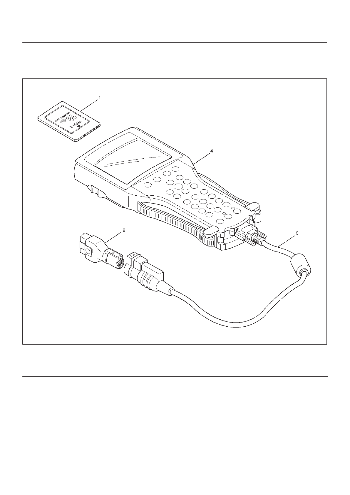
Tech 2 Scan Tool
From 98 MY, Isuzu dealer service departments are
recommended to use T ech 2. Please refer to Tech 2 scan
tool user guide.
BRAKE CONTROL SYSTEM
5A–13
Legend
(1) PCMCIA Card
(2) SAE 16/19 Adaptor
901RW257
(3) DLC Cable
(4) Tech–2
5A–14
BRAKE CONTROL SYSTEM
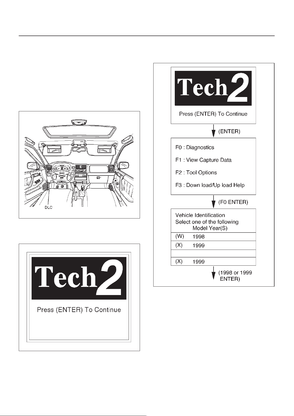
Getting Started
D Before operating the Isuzu PCMCIA card with the
Tech 2, the following steps must be performed:
1.The Isuzu 98 System PCMCIA card (1) inserts into
the Tech 2 (4).
2.Connect the SAE 16/19 adapter (2) to the DLC cable
(3).
3.Connect the DLC cable to the Tech 2 (4).
4.Make sure the vehicle ignition is off.
5.Connect the Tech 2 SAE 16/19 adapter to the vehicle
DLC.
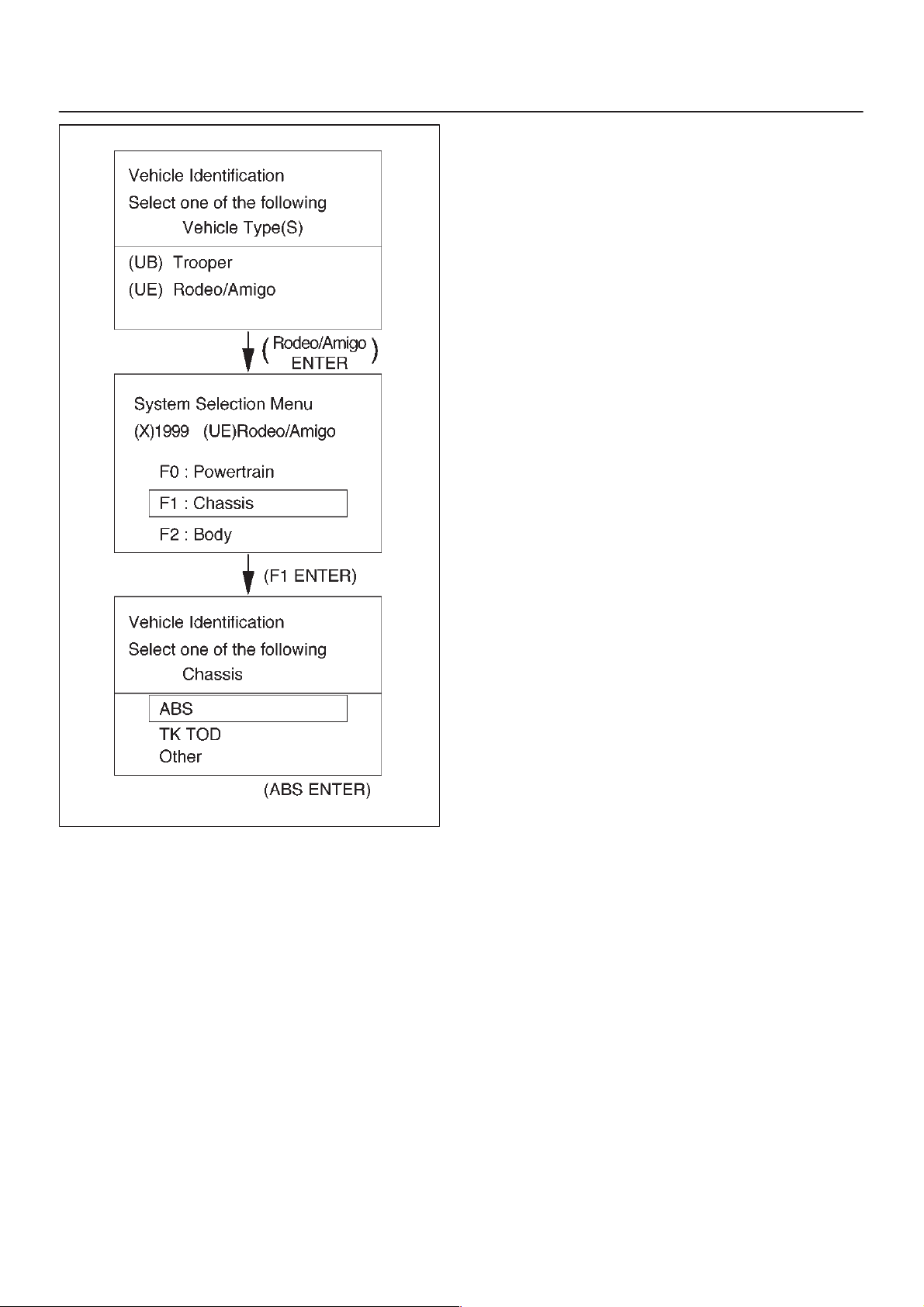
Operating Procedure
The power up screen is displayed when you power up the
tester with the Isuzu systems PCMCIA card. Follow the
operating procedure below.
6.The vehicle ignition turns on.
7.Power up the Tech 2.
8.Verify the Tech 2 power up display.
740RW060
060RX065
060RW009
BRAKE CONTROL SYSTEM
5A–15
060RX063
5A–16
BRAKE CONTROL SYSTEM
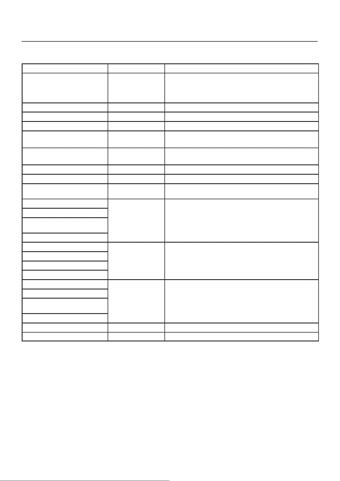
DATA LIST
The data displayed by DAT A LIST are as follows:
Display
Front Left Wheel Speed
Front Right Wheel Speed
Rear Wheel Speeds
Warning Lamp ON/OFF D T o be OFF usually
ABS State ON/OFF D T o be OFF usually
ABS Relay Active/Inactive D To be Active usually
4 Wheel Drive Active/Inactive D 2WD: Inactive
Brake Switch Active/Inactive D Inactive (Released)
Brake Fluid Level Normal or not D To be Normal usually
Return Pump Active/Inactive D To be Inactive usually
DRP (Dynamic Rear Propor-
tioning)
Rear Dump Valve Commanded
Rear Dump Valve Feedback
Rear Isolation Valve Comman-
ded
Rear Isolation Valve Feedback
FL Dump Valve Commanded
FL Dump Valve Feedback
FL Isolation Valve Commanded
FL Isolation Valve Feedback
FR Dump Valve Commanded
FR Dump Valve Feedback
FR Isolation Valve Comman-
ded
FR Isolation Valve Feedback
G–Sensor Voltage D 0.00V when vehicle is stopped
Battery Voltage V oltage D Between 10–16.9V
Content OK/NG Criteria for Data
km/h (MPH) D Start the vehicle and make sure of linear change in
each wheel speed.
D Turn each wheel by hand and make sure that each
speed data change.
D 4WD: Active
D Active (Pressed)
Active/Inactive D To be Inactive usually
Active/Inactive D To be Inactive usually
Active/Inactive D To be Inactive usually
Active/Inactive D To be Inactive usually
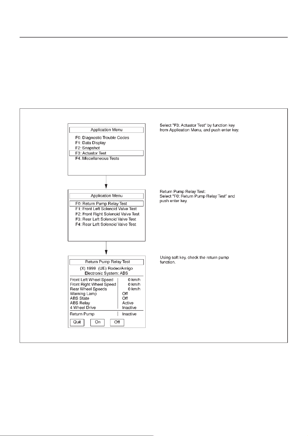
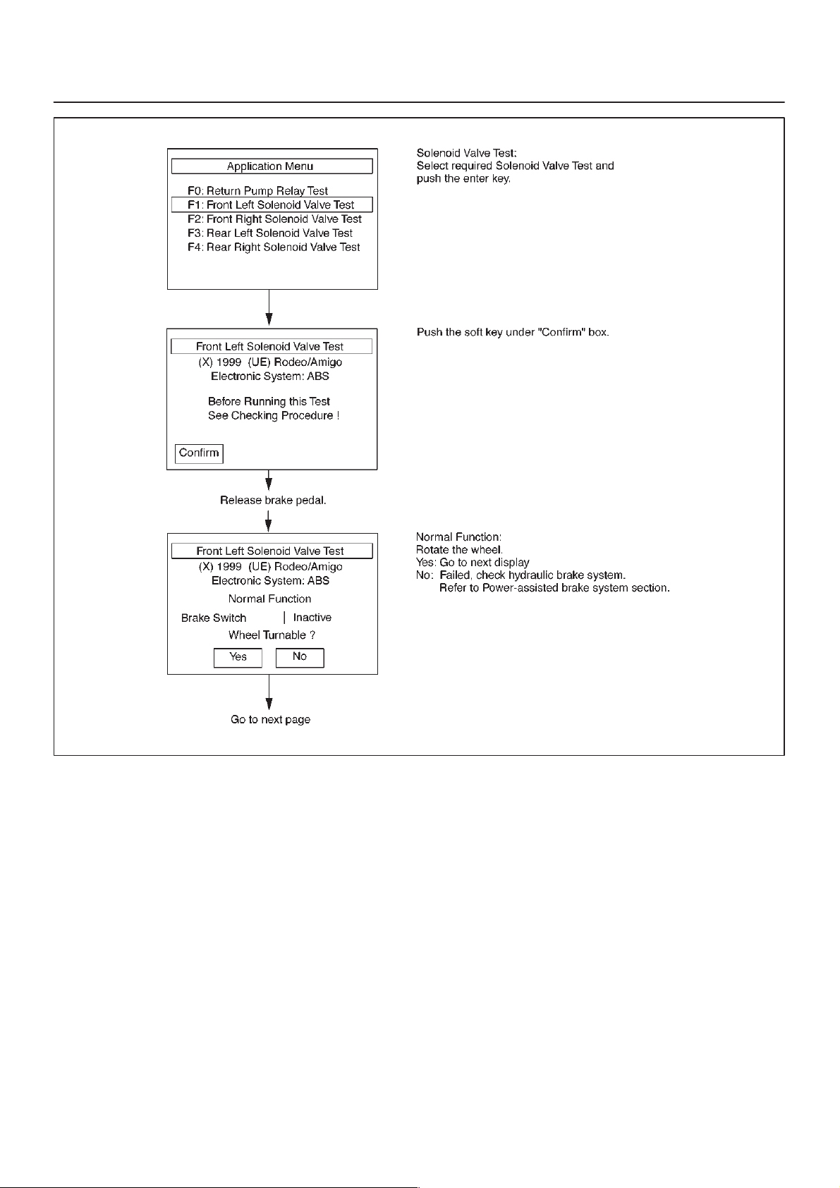
ACTUATOR TEST
This mode is used to exercise the ABS actuators and
make sure they operate normally. Prior to the test, pay
attention to the cautions below. (When checking the
solenoid valve system, be sure to jack up the vehicle.)
CAUTION:
D Before testing, be sure that the brakes work normally .
D Make sure that the battery is fully charged.Conduct
the test by two persons (A TECH 2 operator and a
vehicle checker).
BRAKE CONTROL SYSTEM
5A–17
D Be sure to start ACTUATOR TEST with the engine
stopped.
D Before testing, make sure that electrical trouble, if
any , has been completely repaired. Conducting tests
of ABS solenoid with electrical circuit problem
remaining uncorrected could damage the control unit.
F05RX001
5A–18
BRAKE CONTROL SYSTEM
F05RX002
 Loading...