

Page 1

2006 W-S
Introduction
Installation of Body & Special Equipment
Body Application Summary Chart
Mechanical & Cab Specifications
Weight Distribution
Weights, Commodities & Materials
Vehicle Specifications
NPR/W3500, NPR HD/W4500 Gas
NPR/W3500, NPR HD/W4500 Diesel
NQR/W5500
NPR HD/W4500, NQR/W5500 Crew Cab
NRR/W5500 HD
Electrical
ERIES
(C
HEVROLET
& GMC) N-S
INDEX
ERIES
(I
SUZU
)
NPR/W3500, NPR HD/W4500 Gas
NPR/W3500, NPR HD/W4500, NQR/W5500 Diesel, NRR/W5500 HD Diesel
2005 PTO Section for the 4HK1-TC Engine (IL5)
Miscellaneous
Low Speed Applications for N & W-Series Chassis
Diesel Air Cleaner Canister Change Comparison Diagram
General Motors Isuzu Commercial Truck, LLC (GMICT) and American Isuzu Motors Inc. is striving to provide you with the most up-to-date and accurate
information possible. If you have any suggestion to improve the Body Builder’s Guide, please call GMICT Application Engineering. In the West Coast call 1-562-229-5314 and
in the East Coast call 1-678-240-9818.
Notice of Rights All rights reserved. No part of this book may be reproduced or transmitted in any form or by any means, electronic, mechanical, recording or otherwise,
without prior written permission.
Notice of Liability All specifications contained in this Body Builders Guide are based on the latest product information available at the time of publication. The manufacturer
reserves the right to discontinue or change at any time, without prior notice, any parts, materials, colors, special equipment, specifications, designs and models.
2006 GM/Isuzu Truck
Page 2

2006 W-S
INTRODUCTION......................................................................................................................................................................................... 1
FMVSS Chart................................................................................................................................................................................... 2-3
EPA Requirements .......................................................................................................................................................................... 4-5
INSTALLATION OF BODY AND SPECIAL EQUIPMENT ........................................................................................................................... 6
Clearances ......................................................................................................................................................................................... 6
Engine ......................................................................................................................................................................................... 6
Transmission ............................................................................................................................................................................... 6
Front and Center Propeller Shafts ............................................................................................................................................... 7
Rear Propeller Shaft .................................................................................................................................................................... 8
Exhaust System .......................................................................................................................................................................... 8
Rear Wheel and Axle ................................................................................................................................................................... 9
Other Clearances ........................................................................................................................................................................ 9
Body Installations ............................................................................................................................................................................ 10
Chassis ..................................................................................................................................................................................... 10
ERIES
(C
HEVROLET
& GMC) N-S
ERIES
(I
SUZU
)
PAGE
i
Special Equipment on the Chassis ............................................................................................................................................ 10
Subframe Design and Mounting ................................................................................................................................................ 10
Subframe Contour ..................................................................................................................................................................... 11
Prohibited Attachment Areas.......................................................................................................................................................... 12
Subframe Mounting ......................................................................................................................................................................... 13
Bracket Installation .................................................................................................................................................................... 13
U-bolt Installation ...................................................................................................................................................................... 14
Crew Cab Body/Frame Requirements ........................................................................................................................................... 14
Modification of the Frame ............................................................................................................................................................... 15
Working on Chassis Frame ........................................................................................................................................................ 15
Drilling and Welding ................................................................................................................................................................... 15
Reinforcement of Chassis Frame............................................................................................................................................... 16
2006 GM/Isuzu Truck
Page 3

2006 W-S
INSTALLATION OF BODY AND SPECIAL EQUIPMENT – Modification of the Frame – (Continued)
Welding ..................................................................................................................................................................................... 16
Fluid Lines ........................................................................................................................................................................................ 17
Preparation of Additional Lines .................................................................................................................................................. 17
Installation of Additional Lines ................................................................................................................................................... 18
Electrical Wiring and Harnessing ................................................................................................................................................... 18
Wiring ................................................................................................................................................................................... 19-20
Wire Color Code ........................................................................................................................................................................ 21
Maximum Allowable Current .......................................................................................................................................................... 21
Electrical System Modifications ................................................................................................................................................. 22
Exhaust System ............................................................................................................................................................................... 22
Fuel System ..................................................................................................................................................................................... 23
Rear Lighting ................................................................................................................................................................................... 23
Serviceability .................................................................................................................................................................................... 23
ERIES
(C
HEVROLET
& GMC) N-S
ERIES
(I
SUZU
)
PAGE
ii
Wheelbase Alteration ...................................................................................................................................................................... 24
Shortening/Lengthening the Wheelbase Without Altering the Frame ......................................................................................... 24
Altering the Wheelbase by Altering the Frame ........................................................................................................................... 24
Glossary of Terms – Chassis Wheelbase Alteration ................................................................................................................... 24
BODY APPLICATION SUMMARY CHART .............................................................................................................................................. 30
2006 Gas and 2006 Diesel Model Year Body Application Summary Chart ........................................................................... 30-31
NPR/W3500, NPR HD/W4500 Gas .................................................................................................................................................. 32
2006 Model Year – Body & Payload Weight Distribution (% Front/% Rear) – Automatic Transmission ...................................... 32
NPR/W3500, NPR HD/W4500 Diesel .............................................................................................................................................. 33
2006 Model Year – Body & Payload Weight Distribution (% Front/% Rear) – Manual/Automatic Transmission ......................... 33
NQR/W5500 Diesel .......................................................................................................................................................................... 34
2006 Model Year – Body & Payload Weight Distribution (% Front/% Rear) – Manual/Automatic Transmission ......................... 34
2006 GM/Isuzu Truck
Page 4

2006 W-S
BODY APPLICATION SUMMARY CHART– NPR/W5500 HD Diesel – (Continued)
NRR/W5500 HD Diesel .................................................................................................................................................................... 34
2006 Model Year – Body & Payload Weight Distribution (% Front/% Rear) – Manual/Automatic Transmission ......................... 34
NPR HD/W4500, NQR/W5500 Crew Cab Diesel ............................................................................................................................ 35
2006 Model Year – Diesel Crew Cab Body & Payload Weight Distribution (% Front/% Rear) .................................................... 35
MECHANICAL AND CAB SPECIFICATIONS........................................................................................................................................... 36
Engine Horsepower & Torque Chart............................................................................................................................................... 36
GVW/GCW Ratings .......................................................................................................................................................................... 36
Rear Frame Height Chart ................................................................................................................................................................ 37
Clutch Engagement Torque ............................................................................................................................................................ 37
Paint Code Chart ............................................................................................................................................................................. 38
CV Chart 2 ........................................................................................................................................................................................ 39
N/W Series Towing Procedure ........................................................................................................................................................ 40
Front End Towing (Front Wheels Off the Ground)....................................................................................................................... 40
ERIES
(C
HEVROLET
& GMC) N-S
ERIES
(I
SUZU
)
PAGE
iii
Front End Towing (All Wheels On the Ground) ........................................................................................................................... 41
Rear End Towing (Rear Wheels Off the Ground) ........................................................................................................................ 42
Special Towing Instructions ....................................................................................................................................................... 43
WEIGHT DISTRIBUTION CONCEPTS ..................................................................................................................................................... 44
Weight Restrictions ......................................................................................................................................................................... 44
Gross Axle Weight Rating ............................................................................................................................................................... 45
Weighing the Vehicle ....................................................................................................................................................................... 45
Tire Inflation ..................................................................................................................................................................................... 45
Center of Gravity.............................................................................................................................................................................. 45
Weight Distribution ..................................................................................................................................................................... 46-47
Glossary of Dimensions .................................................................................................................................................................. 48
Weight Distribution Formulas ......................................................................................................................................................... 49
2006 GM/Isuzu Truck
Page 5

2006 W-S
WEIGHT DISTRIBUTION CONCEPTS – (Continued)
Basic Formulas .......................................................................................................................................................................... 50
Weight Distribution Formulas in Words..................................................................................................................................... 50-55
Recommended Weight Distribution % of Gross Vehicle Weight by Axle ..................................................................................... 55
Conventional (2 Axle) ................................................................................................................................................................. 55
COE (2 Axle) .............................................................................................................................................................................. 55
Conventional (3 Axle) ................................................................................................................................................................. 56
COE (3 Axle) .............................................................................................................................................................................. 56
Trailer Weight ................................................................................................................................................................................... 57
Payload at Kingpin .................................................................................................................................................................... 58
Payload at Rear Tandem ........................................................................................................................................................... 58
Performance Calculations .............................................................................................................................................................. 59
1. Speed Formula ...................................................................................................................................................................... 59
2. Grade Horsepower Formula .................................................................................................................................................. 60
ERIES
(C
HEVROLET
& GMC) N-S
ERIES
(I
SUZU
)
PAGE
iv
3. Air Resistance Horsepower Formula ..................................................................................................................................... 61
4. Engine Horsepower Formula ................................................................................................................................................. 62
5. Gradeability Formula ............................................................................................................................................................. 63
6. Startability Formula................................................................................................................................................................ 64
7. Vertical Center of Gravity Formula .................................................................................................................................... 65-66
8. Horizontal Center of Gravity Formula................................................................................................................................ 67-68
Highway System Limits ................................................................................................................................................................... 69
Bridge Formula Definitions ........................................................................................................................................................ 69
Exception to the Bridge Formula ............................................................................................................................................... 70
Other Federal Provisions ........................................................................................................................................................... 70
Federal Bridge Formula Table .................................................................................................................................................... 71-73
COMMODITY AND MATERIAL WEIGHTS .............................................................................................................................................. 74
2006 GM/Isuzu Truck
Page 6

2006 W-S
COMMODITY AND MATERIAL WEIGHTS – (Continued)
Approximate Weights of Commodities and Materials ............................................................................................................. 74-80
VEHICLE SPECIFICATIONS INDEX ......................................................................................................................................................... 81
NPR/W3500, NPR HD/W4500 Gas .................................................................................................................................................. 81
Specifications .......................................................................................................................................................................... 81
Vehicle Weights, Dimensions and Ratings............................................................................................................................. 82
Variable Chassis Dimensions ............................................................................................................................................. 83
Dimension Constants 12,000 GVW ................................................................................................................................... 83
12,000-lb. GVWR with 4L80-E Hydra-Matic Transmission Model California ...................................................................... 83
12,000-lb. GVWR with 4L80-E Hydra-Matic Transmission Model Federal ......................................................................... 84
Dimension Constants 14,500 GVW ................................................................................................................................... 84
14,500-lb. GVWR with 4L30-E Hydra-Matic Transmission Model California/Federal ......................................................... 84
Vehicle Weight Limits......................................................................................................................................................... 85
Frame and Crossmember Specifications .............................................................................................................................. 86
ERIES
(C
HEVROLET
& GMC) N-S
ERIES
(I
SUZU
)
PAGE
v
Frame Chart ............................................................................................................................................................................. 87
Auxiliary Views ......................................................................................................................................................................... 88
Body Builder Weight Information Chart ................................................................................................................................. 89
Cab Tilt .............................................................................................................................................................................. 89
Center of Gravity ............................................................................................................................................................... 90
Front Axle Chart....................................................................................................................................................................... 91
Rear Axle Chart ....................................................................................................................................................................... 92
Definitions ......................................................................................................................................................................... 93
Formulas for Calculating Rear Width and Height Dimensions ........................................................................................... 93
Suspension Deflection Charts – NPR/W3500 Gas, NPR HD/W4500 Gas ............................................................................. 94
Tire and Disc Wheel Chart – NPR/W3500 .............................................................................................................................. 95
Tire .................................................................................................................................................................................... 95
2006 GM/Isuzu Truck
Page 7

2006 W-S
VEHICLE SPECIFICATIONS INDEX – NPR/W3500, NPR HD/W4500 Gas – (Continued)
Disc Wheel ........................................................................................................................................................................ 95
Tire and Disc Wheel Chart – NPR HD/W4500 ........................................................................................................................ 96
Tire .................................................................................................................................................................................... 96
Disc Wheel ........................................................................................................................................................................ 96
Propeller Shaft .................................................................................................................................................................... 97-98
Brake System Diagram, 12,000 GVW ..................................................................................................................................... 99
Vacuum Over Hydraulic ..................................................................................................................................................... 99
Brake System Diagram, 14,500 GVW ................................................................................................................................... 100
Vacuum Over Hydraulic ................................................................................................................................................... 100
Through the Rail Fuel Fill ...................................................................................................................................................... 101
Installation Instructions .................................................................................................................................................... 101
Rear View Fuel Fill ......................................................................................................................................................... 102
Top View Fuel Fill ........................................................................................................................................................... 103
ERIES
(C
HEVROLET
& GMC) N-S
ERIES
(I
SUZU
)
PAGE
vi
Top View ......................................................................................................................................................................... 104
Through the Rail Fuel Fill Frame Hole .......................................................................................................................... 105
Fuel Fill Parts Illustration .............................................................................................................................................. 106
Fuel Fill Parts List .......................................................................................................................................................... 107
NPR/W3500, NPR HD/W4500 Diesel ............................................................................................................................................ 108
Specifications ........................................................................................................................................................................ 108
Vehicle Weights, Dimensions and Ratings........................................................................................................................... 109
Variable Chassis Dimensions ........................................................................................................................................... 110
Dimension Constants ...................................................................................................................................................... 110
In-Frame Tank 12,000-lb. GVWR Manual Transmission Model ........................................................................................ 110
In-Frame Tank 14,500-lb. GVWR Manual Transmission Model ........................................................................................ 111
In-Frame Tank 12,000-lb. GVWR Automatic Transmission Model ................................................................................... 111
2006 GM/Isuzu Truck
Page 8

2006 W-S
VEHICLE SPECIFICATIONS INDEX – NPR/W3500, NPR HD/W4500 Diesel – (Continued)
In-Frame Tank 14,500-lb. GVWR Automatic Transmission Model ................................................................................... 111
Side-Mounted Tank 12,000-lb. GVWR Manual Transmission Model................................................................................ 112
Side-Mounted Tank 14,500-lb. GVWR Manual Transmission Model................................................................................ 112
Side-Mounted Tank 12,000-lb. GVWR Automatic Transmission Model ........................................................................... 112
Side-Mounted Tank 14,500-lb. GVWR Automatic Transmission Model ........................................................................... 113
Vehicle Weight Limits....................................................................................................................................................... 113
Frame and Crossmember Specifications ............................................................................................................................ 114
Frame Chart ........................................................................................................................................................................... 115
Auxiliary Views ....................................................................................................................................................................... 116
Body Builder Weight Information Chart ............................................................................................................................... 117
Cab Tilt ............................................................................................................................................................................ 117
Center of Gravity ............................................................................................................................................................. 118
Front Axle Chart..................................................................................................................................................................... 119
ERIES
(C
HEVROLET
& GMC) N-S
ERIES
(I
SUZU
)
PAGE
vii
Rear Axle Chart ..................................................................................................................................................................... 120
Definitions ....................................................................................................................................................................... 121
Formulas for Calculating Rear Width and Height Dimensions ......................................................................................... 121
Suspension Deflection Charts .............................................................................................................................................. 122
Tire and Disc Wheel Chart .................................................................................................................................................... 123
Tire .................................................................................................................................................................................. 123
Disc Wheel ...................................................................................................................................................................... 123
Propeller Shaft ................................................................................................................................................................ 124-125
PTO Location, Drive Gear and Opening Information .......................................................................................................... 126
Opening Diagram ............................................................................................................................................................ 127
Brake System Diagram, 12,000 GVW ................................................................................................................................... 128
Vacuum Over Hydraulic ................................................................................................................................................... 128
2006 GM/Isuzu Truck
Page 9

2006 W-S
VEHICLE SPECIFICATIONS INDEX – NPR/W3500, NPR HD/W4500 Diesel – (Continued)
Brake System Diagram, 14,500 GVW ................................................................................................................................... 129
Vacuum Over Hydraulic ................................................................................................................................................... 129
In-Frame Diesel Fuel Filler .................................................................................................................................................... 130
Installation Instructions .................................................................................................................................................... 130
Rear View Fuel Fill ......................................................................................................................................................... 131
Top View Fuel Fill ........................................................................................................................................................... 132
Hose Modification for Various Width Bodies ............................................................................................................... 133
Through the Rail Fuel Fill Frame Hole .......................................................................................................................... 134
Fuel Fill Parts Illustration .............................................................................................................................................. 135
Fuel Fill Parts List .......................................................................................................................................................... 136
NQR/W5500 Diesel ........................................................................................................................................................................ 137
Specifications ........................................................................................................................................................................ 137
Vehicle Weights, Dimensions and Ratings........................................................................................................................... 138
ERIES
(C
HEVROLET
& GMC) N-S
ERIES
(I
SUZU
)
viii
PAGE
Variable Chassis Dimensions ........................................................................................................................................... 139
Dimension Constraints .................................................................................................................................................... 139
In-Frame Tank 17,950-lb. GVWR Manual Transmission Model ........................................................................................ 139
In-Frame Tank 17,950-lb. GVWR Automatic Transmission Model ................................................................................... 140
Side-Mounted Tank 17,950-lb. GVWR Manual Transmission Model................................................................................ 140
Side-Mounted Tank 17,950-lb. GVWR Automatic Transmission Model ........................................................................... 140
Vehicle Weight Limits....................................................................................................................................................... 141
Frame and Crossmember Specifications ............................................................................................................................ 142
Frame Chart ........................................................................................................................................................................... 143
Auxiliary Views ....................................................................................................................................................................... 144
Body Builder Weight Information Chart ............................................................................................................................... 145
Cab Tilt ............................................................................................................................................................................ 145
2006 GM/Isuzu Truck
Page 10

2006 W-S
VEHICLE SPECIFICATIONS INDEX – NQR/W5500 Diesel – (Continued)
Center of Gravity ............................................................................................................................................................. 146
Front Axle Chart..................................................................................................................................................................... 147
Rear Axle Chart ..................................................................................................................................................................... 148
Definitions ....................................................................................................................................................................... 149
Formulas for Calculating Rear Width and Height Dimensions ......................................................................................... 149
Suspension Deflection Charts .............................................................................................................................................. 150
Tire and Disc Wheel Chart .................................................................................................................................................... 151
Tire .................................................................................................................................................................................. 151
Disc Wheel ...................................................................................................................................................................... 151
Propeller Shaft ................................................................................................................................................................ 152-153
PTO Location, Drive Gear and Opening Information .......................................................................................................... 154
Opening Diagram ............................................................................................................................................................ 155
Brake System Diagram ......................................................................................................................................................... 156
ERIES
(C
HEVROLET
& GMC) N-S
ERIES
(I
SUZU
)
PAGE
ix
Hydraulic Brake Booster ................................................................................................................................................. 156
Diesel Fuel Fill ........................................................................................................................................................................ 157
Installation Instructions .................................................................................................................................................... 157
Rear View Fuel Fill ......................................................................................................................................................... 158
Top View Fuel Fill ........................................................................................................................................................... 159
Hose Modification for Various Width Bodies ............................................................................................................... 160
Through the Rail Fuel Fill Frame Hole .......................................................................................................................... 161
NQR/W5500 Diesel Fuel Fill Parts Illustration .............................................................................................................. 162
NQR/W5500 Diesel Fuel Fill Parts List ......................................................................................................................... 163
NPR HD/W4500, NQR/W5500 Crew Cab Diesel .......................................................................................................................... 164
Specifications ........................................................................................................................................................................ 164
Vehicle Weights, Dimensions and Ratings........................................................................................................................... 165
2006 GM/Isuzu Truck
Page 11

2006 W-S
VEHICLE SPECIFICATIONS INDEX – NPR HD/W4500, NQR/W5500 Crew Cab Diesel – (Continued)
NPR HD/W4500 Variable Chassis Dimensions ................................................................................................................ 166
NPR HD/W4500 Dimension Constants ........................................................................................................................... 166
NPR HD/W4500 In-Frame Tank 14,500-lb. GVWR Automatic Transmission Model ......................................................... 166
NPR HD/W4500 Side-Mounted Tank 14,500-lb. GVWR Automatic Transmission Model................................................. 166
NQR/W5500 Variable Chassis Dimensions ...................................................................................................................... 167
NQR/W5500 Dimension Constraints ............................................................................................................................... 167
NQR/W5500 In-Frame Tank 17,950-lb. GVWR Automatic Transmission Model .............................................................. 167
NQR/W5500 Side-Mounted Tank 17,950-lb. GVWR Automatic Transmission Model ...................................................... 167
Vehicle Weight Limits....................................................................................................................................................... 168
Frame and Crossmember Specifications ............................................................................................................................ 169
Frame Chart ........................................................................................................................................................................... 170
Auxiliary Views ....................................................................................................................................................................... 171
Body Builder Weight Information Chart ............................................................................................................................... 172
ERIES
(C
HEVROLET
& GMC) N-S
ERIES
(I
SUZU
)
PAGE
x
NPR HD/W4500 .............................................................................................................................................................. 172
Center of Gravity ............................................................................................................................................................. 172
NQR/W5500 .................................................................................................................................................................... 173
Center of Gravity ............................................................................................................................................................. 173
Front Axle Chart NPR HD/W4500 ......................................................................................................................................... 174
Front Axle Chart NQR/W5500 ............................................................................................................................................... 175
Rear Axle Chart NPR HD/W4500 .......................................................................................................................................... 176
Definitions ....................................................................................................................................................................... 177
Formulas for Calculating Rear Width and Height Dimensions ......................................................................................... 177
Rear Axle Chart NQR/W5500 ................................................................................................................................................ 178
Definitions ....................................................................................................................................................................... 179
Formulas for Calculating Rear Width and Height Dimensions ......................................................................................... 179
2006 GM/Isuzu Truck
Page 12

2006 W-S
VEHICLE SPECIFICATIONS INDEX – NPR HD/W4500, NQR/W5500 Crew Cab Diesel – (Continued)
Suspension Deflection Charts NPR HD/W4500 ................................................................................................................... 180
Suspension Deflection Charts NQR/W5500......................................................................................................................... 181
Tire and Disc Wheel Chart NPR HD/W4500 ......................................................................................................................... 182
Tire .................................................................................................................................................................................. 182
Disc Wheel ...................................................................................................................................................................... 182
Tire and Disc Wheel Chart NQR/W5500 ............................................................................................................................... 183
Tire .................................................................................................................................................................................. 183
Disc Wheel ...................................................................................................................................................................... 183
Propeller Shaft NPR HD/W4500 ............................................................................................................................................ 184
Propeller Shaft NQR/W5500........................................................................................................................................... 185-186
PTO Location, Drive Gear and Opening Information .......................................................................................................... 187
Opening Diagram ............................................................................................................................................................ 188
Brake System Diagram 14,500 GVW .................................................................................................................................... 189
ERIES
(C
HEVROLET
& GMC) N-S
ERIES
(I
SUZU
)
PAGE
xi
Vacuum Over Hydraulic ................................................................................................................................................... 189
Brake System Diagram 17,950 GVW .................................................................................................................................... 190
Vacuum Over Hydraulic ................................................................................................................................................... 190
Diesel Fuel Fill ........................................................................................................................................................................ 191
Installation Instructions .................................................................................................................................................... 191
Rear View Fuel Fill ......................................................................................................................................................... 192
Top View Fuel Fill ........................................................................................................................................................... 193
Hose Modification for Various Width Bodies ............................................................................................................... 194
Through the Rail Fuel Fill Frame Hole .......................................................................................................................... 195
Fuel Fill Parts Illustration .............................................................................................................................................. 196
Fuel Fill Parts List .......................................................................................................................................................... 197
NRR/W5500-HD ............................................................................................................................................................................. 198
2006 GM/Isuzu Truck
Page 13

2006 W-S
VEHICLE SPECIFICATIONS INDEX – NRR/W5500-HD – (Continued)
Specifications ........................................................................................................................................................................ 198
Vehicle Weights, Dimensions and Ratings........................................................................................................................... 199
Variable Chassis Dimensions ........................................................................................................................................... 200
Dimension Constraints .................................................................................................................................................... 200
In-Frame Tank 19,500-lb. GVWR Manual Transmission Model ........................................................................................ 200
In-Frame Tank 19,500-lb. GVWR Automatic Transmission Model ................................................................................... 201
Side-Mounted Tank 19,500-lb. GVWR Manual Transmission Model................................................................................ 201
Side-Mounted Tank 19,500-lb. GVWR Automatic Transmission Model ........................................................................... 201
Vehicle Weight Limits....................................................................................................................................................... 202
Frame and Crossmember Specifications ............................................................................................................................ 203
Frame Chart ........................................................................................................................................................................... 204
Auxiliary Views ....................................................................................................................................................................... 205
Body Builder Weight Information Chart ............................................................................................................................... 206
ERIES
(C
HEVROLET
& GMC) N-S
ERIES
(I
SUZU
)
PAGE
xii
Cab Tilt ............................................................................................................................................................................ 206
Center of Gravity ............................................................................................................................................................. 207
Front Axle Chart..................................................................................................................................................................... 208
Rear Axle Chart ..................................................................................................................................................................... 209
Definitions ....................................................................................................................................................................... 210
Formulas for Calculating Rear Width and Height Dimensions ......................................................................................... 210
Suspension Deflection Charts .............................................................................................................................................. 211
Tire and Disc Wheel Chart .................................................................................................................................................... 212
Tire .................................................................................................................................................................................. 212
Disc Wheel ...................................................................................................................................................................... 212
Propeller Shaft ................................................................................................................................................................ 213-214
PTO Location, Drive Gear and Opening Information .......................................................................................................... 215
2006 GM/Isuzu Truck
Page 14

2006 W-S
VEHICLE SPECIFICATIONS INDEX – NRR/W5500-HD – (Continued)
Opening Diagram ............................................................................................................................................................ 216
Brake System Diagram ......................................................................................................................................................... 217
Hydraulic Brake Booster ................................................................................................................................................. 217
Diesel Fuel Fill ........................................................................................................................................................................ 218
Installation Instructions .................................................................................................................................................... 218
Rear View Fuel Fill ......................................................................................................................................................... 219
Top View Fuel Fill ........................................................................................................................................................... 220
Hose Modification for Various Width Bodies ............................................................................................................... 221
Through the Rail Fuel Fill Frame Hole .......................................................................................................................... 222
NRR/W5500-HD Diesel Fuel Fill Parts Illustration ....................................................................................................... 223
NRR/W5500-HD Diesel Fuel Fill Parts List ................................................................................................................... 224
NPR/W3500, NPR HD/W4500 Gas Electrical................................................................................................................................ 225
Symbols.................................................................................................................................................................................. 225
ERIES
(C
HEVROLET
& GMC) N-S
ERIES
(I
SUZU
)
xiii
PAGE
Abbreviations ......................................................................................................................................................................... 226
Wiring ..................................................................................................................................................................................... 227
Wire Color ....................................................................................................................................................................... 227
Distinction of Circuit by Wire Base Color ......................................................................................................................... 228
Wire Size .................................................................................................................................................................. 228-229
Grounding Point Location (P-5, E-53, E-54) ......................................................................................................................... 230
Grounding Point Location (E-55, E-56, E-38, E-106, E-39, E-129) ...................................................................................... 231
Grounding Point Location (J-9, J-167) ................................................................................................................................. 232
Grounding Point Location (E-39, E-129, E-38, E-106).......................................................................................................... 233
Reference Table of Grounding Points .................................................................................................................................. 234
NPR/W3500 Body Room Light, ID and Marker Lamp, and Back-Up Lamp Connector Location..................................... 235
NPR/W3500 Body Connectors LH Frame ....................................................................................................................... 235
2006 GM/Isuzu Truck
Page 15

2006 W-S
VEHICLE SPECIFICATIONS INDEX – NPR/W3500, NPR HD/W4500 Gas Electrical – (Continued)
NPR/W3500 Body Connectors EOF ................................................................................................................................ 236
Fuse Location ........................................................................................................................................................................ 237
Fuse Box ................................................................................................................................................................................ 238
Relay Location ....................................................................................................................................................................... 239
Diode Location ...................................................................................................................................................................... 240
Headlights .............................................................................................................................................................................. 241
Marker Lights and Tail Lights ............................................................................................................................................... 242
Turn Signals ........................................................................................................................................................................... 243
Horn, Backup Light, Backup Buzzer Circuit ........................................................................................................................ 244
Cab Interior Lights, Rear Body Interior Light Circuit........................................................................................................... 245
Radio and Cigar Lighter Circuit ............................................................................................................................................ 246
Auxiliary Power Source Circuit Diagram.............................................................................................................................. 247
03 Model Year Fuel Tank Sending Unit Resistance Values ................................................................................................. 248
ERIES
(C
HEVROLET
& GMC) N-S
ERIES
(I
SUZU
)
xiv
PAGE
04i Model Year Fuel Tank Sending Unit Resistance Values ................................................................................................ 249
NPR/W3500, NPR HD/W4500, NQR/W5500 Diesel Electrical ..................................................................................................... 250
Symbols.................................................................................................................................................................................. 250
Abbreviations ......................................................................................................................................................................... 251
Wiring ..................................................................................................................................................................................... 252
Wire Color ....................................................................................................................................................................... 252
Distinction of Circuit by Wire Base Color ......................................................................................................................... 253
Wire Size ......................................................................................................................................................................... 253
Grounding Point Location (P-5, E-136)................................................................................................................................. 255
Grounding Point Location (B-1, B-7) .................................................................................................................................... 256
Grounding Point Location (J-9)............................................................................................................................................. 257
Reference Table of Grounding Point .................................................................................................................................... 258
2006 GM/Isuzu Truck
Page 16

2006 W-S
VEHICLE SPECIFICATIONS INDEX – NPR/W3500, NPR HD/W4500, NQR/W5500 Diesel Electrical – (Continued)
NPR/W3500, NQR/W5500 Body Room Light, ID and Marker Lamp, and Back-Up Lamp Connector Location .............. 259
NPR/W3500, NQR/W5500 Body Connectors LH Frame ................................................................................................. 259
NPR/W3500, NQR/W5500 Body Connectors EOF .......................................................................................................... 260
Fuse Location ........................................................................................................................................................................ 261
Fuse Box ................................................................................................................................................................................ 262
Relay Location ....................................................................................................................................................................... 263
Diode Location ...................................................................................................................................................................... 264
Headlights .............................................................................................................................................................................. 265
Marker Lights and Horns ...................................................................................................................................................... 266
Turn Signals Front ................................................................................................................................................................. 267
Turn Signals Rear and Back Buzzer Circuit ......................................................................................................................... 268
Cab Interior Lights and Body Connectors ........................................................................................................................... 269
Radio and Cigar Lighter Circuits .......................................................................................................................................... 270
ERIES
(C
HEVROLET
& GMC) N-S
ERIES
(I
SUZU
)
PAGE
xv
Auxiliary Power Source Circuit Diagram.............................................................................................................................. 271
Fuel Tank Sending Unit Resistance (In-Frame Tank), (Side-Mounted Tank) ............................................................... 272-273
NPR/W3500, NPR HD/W4500, NQR/W5500, NRR/W5500-HD, 2005 PTO Section for the 4HK1-TC Engine (IL5) .................... 274
Section Outline ...................................................................................................................................................................... 274
Overview ................................................................................................................................................................................ 275
Vocation/Modes ..................................................................................................................................................................... 275
Factory Installed Equipment ................................................................................................................................................. 276
Upfitter Installed Equipment ................................................................................................................................................. 276
ECM Programmable PTO Functions .................................................................................................................................... 276
Operation ............................................................................................................................................................................... 276
PTO Switch Description ........................................................................................................................................................ 277
Stationary Preset Mode ................................................................................................................................................. 278-279
2006 GM/Isuzu Truck
Page 17

2006 W-S
VEHICLE SPECIFICATIONS INDEX – NPR/W3500, NPR HD/W4500, NQR/W5500, NRR/W5500-HD – (Continued)
Stationary Variable Mode ............................................................................................................................................... 280-281
Mobile Variable Mode ..................................................................................................................................................... 282-283
PTO Engine Shutdown .......................................................................................................................................................... 284
Remote Operation ................................................................................................................................................................. 284
Location of PTO Switch and Indicator ................................................................................................................................. 285
Location of Cruise Control Switches ................................................................................................................................... 286
PTO Switch Connector and Harness ................................................................................................................................... 287
PTO Switch Harness Connector ........................................................................................................................................... 288
PTO Harness 1 Connector (10 Pin) & PTO Harness 2 Connector (8 Pin) ........................................................................... 289
PTO Switch Wiring Diagram ................................................................................................................................................. 290
PTO Harness 1 & 2 Diagram ................................................................................................................................................. 291
Low Speed Application for W and N-Series Chassis .......................................................................................................... 292
NPR/W3500, NPR HD/W4500, NQR/W5500, NRR/W5500 HD Diesel Air Cleaner Canister Change Comparison Diagram .... 293
ERIES
(C
HEVROLET
& GMC) N-S
ERIES
(I
SUZU
)
xvi
PAGE
2006 GM/Isuzu Truck
Page 18

2006 W-S
ERIES
(C
HEVROLET
& GMC) N-S
ERIES
(I
SUZU
)
PAGE
1
INTRODUCTION
This guide has been provided as an aid to final stage manufacturers in determining conformity to the applicable Emission Control and
Federal Motor Vehicle Safety Standards. Final stage manufacturers should maintain current knowledge of all Emission Regulations and
Federal Motor Vehicle Safety Standards and be aware of their specific responsibility in regards to each standard.
Any manufacturer making material alterations to this incomplete vehicle during the process of manufacturing the complete vehicle should be
constantly alert to all effects, direct or indirect, on other components, assemblies or systems caused by such alterations. No alterations
should be made to the incomplete vehicle that directly or indirectly results in any either component, assembly or system being in nonconformance with applicable Emission Regulations or Federal Motor Vehicle Safety Standards.
General Motors Isuzu Commercial Truck, LLC (GMICT) and American Isuzu Motors Inc. will honor its warranty commitment (for the cab-
chassis only), to the ultimate consumer, provided: (1) the final stage manufacturer has not made any alterations or modifications which do
not conform to any applicable laws, regulations or standards, or adversely affect the operation of the cab-chassis; and (2) the final stage
manufacturer complied with the instructions contained in this guide with respect to the completion of the vehicle. Otherwise, the warranty
becomes the responsibility of the final stage manufacturer.
The final stage manufacturer is solely responsible for the final certification of the vehicle and for compliance with Emission Control and
Federal Motor Vehicle Safety Standards. The information contained in this guide has been provided for the final stage manufacturer’s
information and guidance.
This guide contains information pertaining to the: NPR/W3500; NPR-HD/W4500 Gas; NPR/W3500; NPR-HD/W4500 Diesel; NQR/W5500,
NPR-HD/W4500; NQR/W5500 Diesel Crew Cab; and NRR/W5500-HD Series Chassis Cab.
Following is a list of Federal Motor Vehicle Safety Standards applicable to those vehicles with a GVWR greater than 10,000 lbs. Please refer
to the chart on the next page.
2006 GM/Isuzu Truck
Page 19

2006 W-S
ERIES
(C
HEVROLET
& GMC) N-S
ERIES
(I
SUZU
)
PAGE
2
FMVSS Chart
List of Federal or Canadian Motor Vehicle Safety Standards applicable to Isuzu/GMC Truck product lines. Gasoline or diesel fueled vehicles
with GVWR greater than 10,000 lbs. (4536 Kg)
MVSS No.
1106
101
102
103
104
105
106
108
111
113
115
116
120
121
Title NPR/NPR HD
Upper line FMVSS, Lower Line CMVSS W3500/W4500
N/A
Exterior Noise
Controls and Displays
Location and Identification of controls and displays
Transmission shift lever sequence, starter interlock and transmission braking effect
Transmission control functions
Windshield defrosting and defogging systems
Windshield defrosting and defogging
Windshield wiping and washing systems
Windshield wiping and washing systems
Hydraulic and electric brake systems
Hydraulic and electric brake systems
Brake hoses
Brake hoses
Lamps and reflective devices and associated equipment
Lighting systems and reflective devices
Rear view mirrors
Mirrors
Hood latch system
Hood latch system
N/A
Vehicle identification system
Motor vehicle brake fluids
Hydraulic brake fluids
Tire selection and rims for vehicles other than passenger cars
Tire selection and rims for vehicles other than passenger cars
Air brake systems
Air brake systems
2
NQR/NRR
W5500/W5500-HD
11
11
11
11
11
22
11
22
11
11
11
11
22
33
2006 GM/Isuzu Truck
Page 20
2006 W-S
ERIES
(C
HEVROLET
& GMC) N-S
ERIES
(I
SUZU
)
PAGE
3
FMVSS Chart (continued)
List of Federal or Canadian Motor Vehicle Safety Standards applicable to Isuzu/GMC Truck product lines. Gasoline or diesel fueled vehicles
with GVWR greater than 10,000 lbs. (4536 Kg)
MVSS No.
124
205
206
207
208
209
210
213 33
213.4 Built in child restraint systems and built in booster cushions
302
Type 1, 2 or 3 numbers to the right hand side of the table designate the appropriate paragraph in the Canadian Motor Vehicle Safety Standards (CMVSS), and Federal Motor Vehicle Safety Standards (FMVSS).
Please see IVD (incomplete vehicle document) for full statements.
Type 1 A statement that the vehicle when completed will conform to the standard if no alterations are made in identified components of the incomplete vehicle.
Type 2 A statement of specific conditions of final manufacture under which the manufacturer specifies that the completed vehicle will conform to the standard.
Type 3 A statement that conformity with the standard cannot be determined based upon the components supplied on the incomplete vehicle, and that the incomplete vehicle manufacturer makes no representation to conformity
with the standard.
NOTE: This chart is only a guide. For complete information, please refer to “Document for Incomplete Vehicle” provided with each chassis.
2006 GM/Isuzu Truck
Accelerator control system
Accelerator control system
Glazing materials
Glazing materials
Door locks and door retention components
Door locks and door retention components
Seating systems
Anchorage of seats
Occupant crash protection
Occupant restraint systems in frontal impacts
Seatbelt assemblies
Seatbelt assemblies
Seatbelt assembly anchorages
Seatbelt assembly anchorages
Child restraint systems
Flammability of interior materials
Flammability
N/A 1, 3 1
On road vehicle and engine emission regulations
N/A 11
ICES-002 Canadian Interference causing equipment standard
Upper line FMVSS, Lower Line CMVSS W3500, W4500
Title NPR, NPR HD/
11
11
11
11
11
11
11
11
NQR/NRR
W5500/W5500-HD
Page 21

2006 W-S
ERIES
(C
HEVROLET
& GMC) N-S
ERIES
(I
SUZU
)
PAGE
4
EPA Requirements
NPR/W3500 Gas, NPR/W3500 Diesel, NQR/W5500 Diesel, NPR HD, NQR/W4500, W5500 Diesel Crew Cab and NRR/W5500-HD
Series Chassis Cab
The following statement is applicable to all models of incomplete vehicles equipped with diesel engines. (Type 1)
This incomplete vehicle, when completed, will conform to the above standard providing no alterations are made which affect the function,
physical, chemical, or mechanical properties, environment, location or vital spatial clearances of the components assemblies or systems
including but not limited to those listed below:
-Injection Pump -Exhaust Gas Re circulation System
-Injector and High Pressure Lines -Engine Coolant Temperature
-Turbocharger -Intake Manifold
-Charge Air Cooler and Charge Air Cooler Hoses -Catalytic Converter and its location
-Engine Control Module (ECM) -Variable Swirl System
-Engine Speed Sensor
The following statement is applicable to all models of incomplete vehicles equipped with gasoline engines. (TYPE 3)
Conformity with on road vehicle and emission regulations cannot be determined based upon the components supplied on the incomplete
vehicle, and ISUZU Motors makes no representation to conformity with the standard
INTERFERENCE CAUSING EQUIPMENT STANDARD ICES –002
The following statement is applicable to NPR/W Series Chassis-Cab (Gasoline Engine Only). TYPE 1
This incomplete vehicle, when completed, will conform to the above regulations providing no alterations are made which affect the
function, physical, chemical, or mechanical properties, environment, location or vital spatial clearances of the components assemblies or
systems including but not limited to those listed below:
-Ignition coils -Ignition Wires and plugs -Spark Plug Wires
To assure that EPA and California Emission Certificate Requirements are met, this Incomplete Vehicle must be completed in strict
accordance with all instructions contained in the incomplete vehicle document, especially the following instructions which relate to:
A. Exhaust emission related components
B. Specifications for fill pipes and openings of motor vehicle fuel tanks (applicable to California gasoline powered vehicles)
C. Labels
2006 GM/Isuzu Truck
Page 22

2006 W-S
A. EXHAUST EMISSION RELATED COMPONENTS
1.Compliance of this vehicle with EPA/California Emission certification requirements will be maintained providing no alterations (except
where noted) are made to the components or systems identified below:
-Air Induction System -Exhaust oxygen sensors (gasoline engine)
-Catalytic Converter System (if equipped) -Exhaust system
-Coolant temperature Sensor -Evaporative emission control system (gasoline engine) *
-Crankcase emission control System -Fuel injection system
-Diesel fuel Injection components and controls -Fuel system
-Engine Assembly -Ignition System (gasoline engine)
-Engine electronics (ECM/PCM/VCM) -Intake Manifold
-Engine Speed Sensor -Turbocharger and associated equipment/controls
-Exhaust Gas Recalculation System
*All Federal/California gasoline powered heavy duty vehicles will have an evaporative emission control system that is certified for a fuel
take capacity that is not to exceed the amount shown on the Vehicle Evaporative Emission Control Information Label. Persons wishing
to add fuel tank capacity above the amount shown must contact CARB and/or submit a written statement to the EPA administrator that
the hydrocarbon storage system has been upgraded according to the requirements of 40 CFR 86-095-35 (g) (2)
2. Compliance with applicable fuel evaporative emission regulations will be maintained if no alteration is made to the fuel filler neck(s).
ERIES
(C
HEVROLET
& GMC) N-S
ERIES
(I
SUZU
)
PAGE
5
Compliance with applicable fuel evaporative emission regulations will be maintained if no alteration is made to change material or
increase the size or length of the following nonmetallic fuel and evaporative emission hoses.
-Fuel feed hose front and rear -Fuel vapor lines at canister
-Fuel return hoses front and rear -Fuel vapor lines from engine to chassis pipes
-Fuel tank filler hoses to filler neck -Fuel vapor lines from fuel tank sender to chassis pipes
-Fuel tank vent hoses to filler neck
B. SPECIFICATIONS FOR FILL PIPES AND OPENINGS OF MOTOR VEHICLE FUEL TANKS (APPLICABLE ONLY TO CALIFORNIA
GASOLINE POWERED VEHICLES
The incomplete vehicle when completed, will conform to Title 13 California Administrative Code Chapter 3 Air Resources Board
Subchapter 7 “ Specifications for Fill Pipes and Openings of Motor Vehicle Fuel Tanks”, if no alterations are made to the fuel filler neck(s).
C. LABELS
The emission control related information labels that are permanently affixed are required by government regulation and must not be
obstructed from view or defaced so as to impair its visibility or legibility.
2006 GM/Isuzu Truck
Page 23
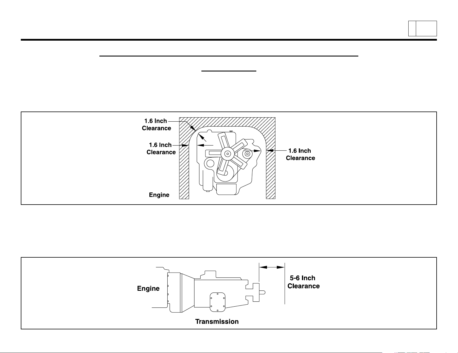
2006 W-S
Engine
At least 1.6 inches of clearance should be maintained around the engine. No obstacles should be added in front of the radiator or intercooler.
ERIES
INSTALLATION OF BODY AND SPECIAL EQUIPMENT
(C
HEVROLET
& GMC) N-S
Clearances
ERIES
(I
SUZU
)
PAGE
6
Transmission
The transmission is removed from the rear. Enough clearance must be provided to allow rearward movement of the transmission
assembly. Clearance should be sufficient to allow 5 to 6 inches of unrestricted movement of the transmission assembly. In addition, provide
at least 2 inches of clearance around the control lever on the side of the transmission to allow free movement without any binding.
(Installation of Body and Special Equipment Section – continued on next page)
2006 GM/Isuzu Truck
Page 24
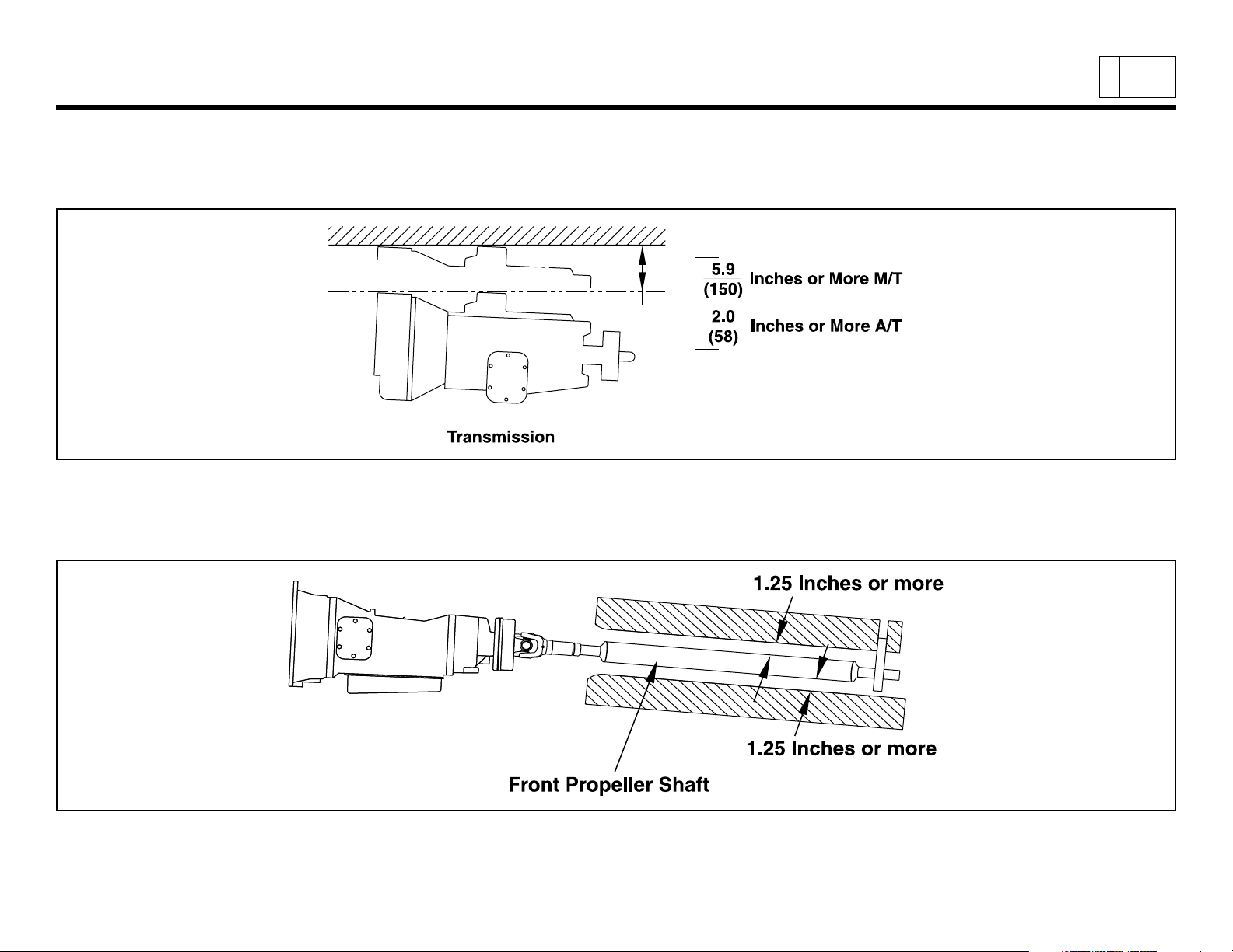
2006 W-S
(Installation of Body and Special Equipment Section – continued from previous page)
At least 6 inches of clearance should be maintained above the transmission to allow easy removal of the upper cover for manual transmissions. At least 2 inches of clearance should be maintained above the automatic transmission to allow for transmission removal.
Front and Center Propeller Shafts
At least 1.25 inches of clearance should be maintained around front and center propeller shafts.
ERIES
(C
HEVROLET
& GMC) N-S
ERIES
(I
SUZU
)
PAGE
7
2006 GM/Isuzu Truck
(Installation of Body and Special Equipment Section – continued on next page)
Page 25
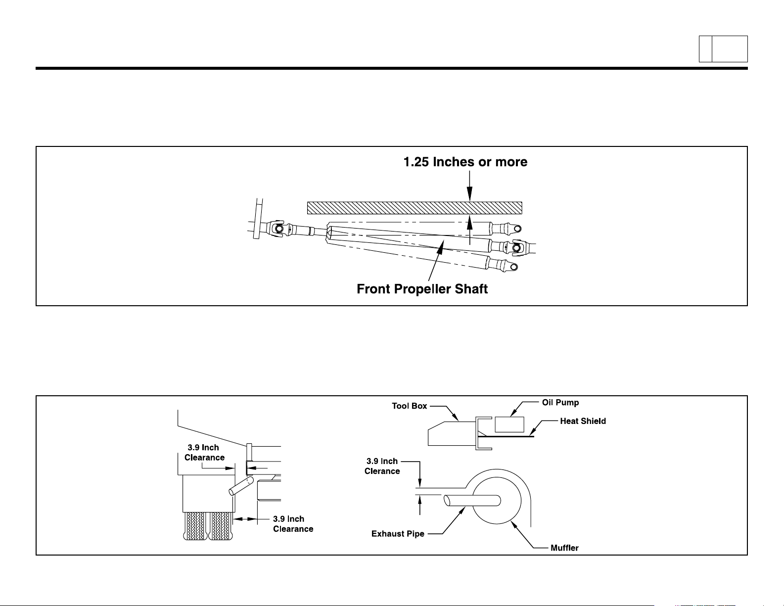
2006 W-S
(Installation of Body and Special Equipment Section – continued from previous page)
Rear Propeller Shaft
With the rear springs at maximum deflection, at least 1.25 inches of clearance should be provided over the rear propeller shaft.
Exhaust System
ERIES
(C
HEVROLET
& GMC) N-S
ERIES
(I
SUZU
)
PAGE
8
If flammable materials such as wood are used in the body, provide at least 3.9 inches of clearance between the body and any parts of the
exhaust pipe, muffler and catalytic converter. If it is impossible to maintain this minimum clearance, use a heat shield. Also use a heat shield
if an oil pump or line is located above the exhaust pipe, muffler or catalytic converter.
(Installation of Body and Special Equipment Section – continued on next page)
2006 GM/Isuzu Truck
Page 26
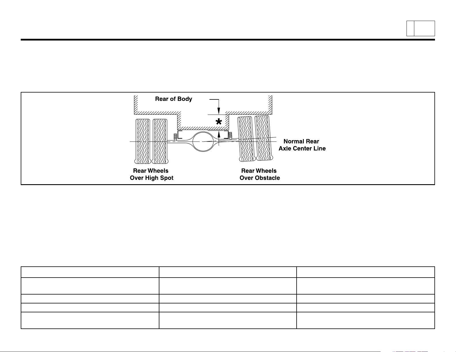
2006 W-S
(Installation of Body and Special Equipment Section – continued from previous page)
Rear Wheel and Axle
The design and installation of the body should allow sufficient clearance for full vertical movement of the rear wheels and axle when the
vehicle travels over rough or unlevel surfaces.
Note: For recommended clearances, please refer to the Rear Axle Chart in each model’s respective section.
ERIES
(C
HEVROLET
& GMC) N-S
ERIES
(I
SUZU
)
PAGE
9
Other Clearances
The transmission control cable may be broken if it is bent by or interferes with the body and its fixtures. To prevent this, 1 inch of minimum
clearance should be provided. When cable is detached from body mounting, be sure not to bend the cable.
Accessibility to the grease nipple on the rear spring bracket/shackle should be provided so that serviceability with a grease gun is not
hampered.
Parts Minimum Clearance Location
Brake Hose
Parking Brake Cable 1.2 in. —
Fuel Hose 1.6 in. —
Shock Absorber
(Installation of Body and Special Equipment Section – continued on next page)
2006 GM/Isuzu Truck
6.7 in. Axle Side
1.6 in. Frame Side
2.4 in. Axle Side
1.2 in. Frame Side
Page 27
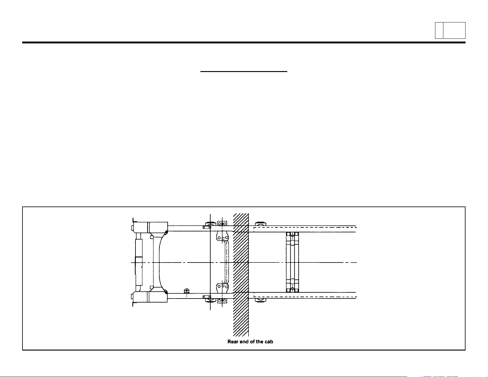
2006 W-S
(Installation of Body and Special Equipment Section – continued from previous page)
Chassis
To maintain the performance of the truck chassis, either a side member or subframe should always be used for body mounting. Body
mounting with low rigidity will often adversely affect riding comfort.
Special Equipment on the Chassis
When installing special equipment on the chassis, extra consideration must be given to the weight and construction of the equipment to
assure proper distribution of the load. Localization of the load should be prevented. All special equipment should be properly secured into
position. We recommend the use of subframe members when installing special equipment.
Subframe Design and Mounting
The subframe assembly should be mounted as close to the cab as possible. It should be contoured to match the shape and dimensions of
the chassis frame as closely as possible.
ERIES
(C
HEVROLET
Body Installation
& GMC) N-S
ERIES
(I
SUZU
)
PAGE
10
2006 GM/Isuzu Truck
(Installation of Body and Special Equipment Section – continued on next page)
Page 28

2006 W-S
(Installation of Body and Special Equipment Section – continued from previous page)
Subframe Contour
Contouring of the front end of the subframe members as shown in the three illustrations below will prevent stresses from being
concentrated on certain areas of the chassis frame.
ERIES
(C
HEVROLET
& GMC) N-S
ERIES
(I
SUZU
)
PAGE
11
2006 GM/Isuzu Truck
(Installation of Body and Special Equipment Section – continued on next page)
Page 29

2006 W-S
(Installation of Body and Special Equipment Section – continued from previous page)
When using a steel subframe, do not close the end of the subframe.
ERIES
(C
HEVROLET
& GMC) N-S
ERIES
(I
SUZU
)
PAGE
12
Prohibited Attachment Areas
Do not attach the subframe with a bolt on bracket to the chassis frame at the points indicated by shading in the following illustrations.
1. At the front end of the subframe. The attaching bolt or bracket must be at least 2 inches behind the kick up point of the subframe.
(Installation of Body and Special Equipment Section – continued on next page)
2006 GM/Isuzu Truck
Page 30
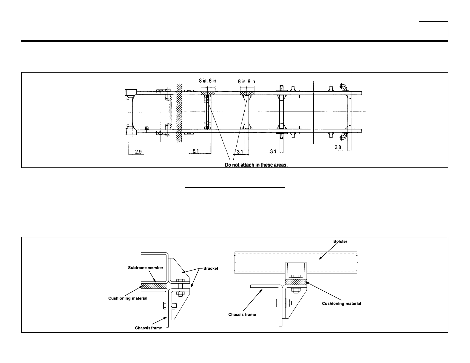
2006 W-S
(Installation of Body and Special Equipment Section – continued from previous page)
2. Within 8 inches of bends in the chassis frame or the attachment points of any crossmembers.
Bracket Installation
ERIES
(C
HEVROLET
Subframe Mounting
& GMC) N-S
ERIES
(I
SUZU
)
PAGE
13
Mounting brackets should be clamped to the chassis frame using bolts. For proper positions in which to install the bolts, refer to the
preceding section and the section “Modifications to the Chassis Frame.”
(Installation of Body and Special Equipment Section – continued on next page)
2006 GM/Isuzu Truck
Page 31

2006 W-S
(Installation of Body and Special Equipment Section – continued from previous page)
U-bolt Installation
When U-bolts are used to retain the subframe, reinforcement blocks must be installed in the frame members. This will prevent distortion of
the frame flange as they are tightened. The drawing indicates the correct placement of reinforcement blocks. If you use wood blocks, be sure
that there is sufficient clearance between them and any parts of the exhaust system.
If any fluid lines or electric cables are located near the reinforcement blocks, you must provide at least 0.4 inches of clearance between rigid
or stationary portions, and at least 1.6 inches between moveable or flexible portions of the lines.
ERIES
(C
HEVROLET
& GMC) N-S
ERIES
(I
SUZU
)
PAGE
14
For the installation positions of the U-bolts, refer to “Prohibited Attachment Areas.”
Crew Cab Body/Frame Requirement
The Crew Cab NPR HD/W4500 and NQR/W5500 will be available in two wheelbases, 150 and 176 inches. Effective CA will be 84.7 and
110.7 inches. On this model chassis, General Motors Isuzu Commercial Truck, LLC (GMICT) and American Isuzu Motors Inc. will require that
the body installed on the chassis have an understructure manufactured with any of the following structural steel “C” channels:
4” x 1-5/8”, 7.25 lbs./ft. = ok
5” x 1-3/4”, 6.7 or 9.0 lbs./ft. = ok
6” x 2”, 8.2, 10.5 or 13.0 lbs./ft. = ok
(Installation of Body and Special Equipment Section – continued on next page)
2006 GM/Isuzu Truck
Page 32

2006 W-S
(Installation of Body and Special Equipment Section – continued from previous page)
ERIES
(C
HEVROLET
& GMC) N-S
ERIES
(I
SUZU
)
PAGE
15
Modification of the Frame
Modifications of the chassis frame should be held to an absolute minimum. Modification work should be performed according to the
instructions in the following paragraphs.
When modification is complete, chassis frame members should be carefully inspected to eliminate the possibility of any safety-related
defects.
NOTE: PLEASE REFER TO NOTES ON CHASSIS FRAME MODIFICATION WITH ANTILOCK BRAKES.
Working on Chassis frame
The chassis frame is designed and built with consideration for proper load distribution. Sufficient physical strength is provided when the load
is evenly distributed. Installation of special equipment on the chassis frame can cause variations in load distribution. If even distribution of
load is not kept in mind when the equipment is installed, localization of stresses on specific areas of the frame could cause cracking of the
chassis frame members or other problems, even if the total weight of the equipment is within the design limit.
The chassis frame is designed as an integral unit. Therefore, we do not recommend cutting the chassis frame under any circumstances.
Drilling and Welding
IMPORTANT NOTE: For vehicles equipped with electronic engines and or electronic or hydra-matic transmissions,
electric arc welding must be done with the negative battery cable disconnected.
1. Do not drill or weld in the shaded portions of the chassis frame members. Do not weld within 0.8 inches from the edges of any
existing holes.
2. Hold the length of any welding beads within 1.2-2.0 inches. Allow at least 1.6 inches between adjacent welding beads.
3. All holes must be drilled. Do not use a torch to make any holes.
4. All riveting must be done with cold rivets. Do not use hot rivets.
5. The flange of the chassis frame must not be cut under any circumstances.
6. The subframe must be attached to the chassis frame with bolts. Do not weld.
(Installation of Body and Special Equipment Section – continued on next page)
2006 GM/Isuzu Truck
Page 33

2006 W-S
(Installation of Body and Special Equipment Section – continued from previous page)
Reinforcement of Chassis Frame
ERIES
(C
HEVROLET
& GMC) N-S
ERIES
(I
SUZU
)
PAGE
16
Reinforcements must be installed to prevent the considerable variation in the section modulus. They must be welded so as to avoid localized
stresses.
The frame of the N and W Series gas and diesel is made of SAPH440 mild steel.
The drawing on the following page illustrates correct and incorrect methods of frame reinforcement.
Welding
1. Keep reinforcement plates and chassis frame free from moisture and water.
2. Avoid cooling with water after welding.
3. Use a suitable means to protect pipes, wires, rubber parts, leaf springs, etc. against heat and effect of sputtering.
4. Remove fuel tank assembly when welding portions near the fuel tank.
5. Remove coat of paint completely when welding painted areas.
(Installation of Body and Special Equipment Section – continued on next page)
2006 GM/Isuzu Truck
Page 34

2006 W-S
(Installation of Body and Special Equipment Section – continued from previous page)
ERIES
(C
HEVROLET
& GMC) N-S
ERIES
(I
SUZU
)
PAGE
17
Fluid Lines
Do not disturb the layout of any brake lines or fuel lines unless absolutely necessary. When modification is needed, follow the instructions
below carefully to ensure safety. Brake fluid lines must not be cut and spliced under any circumstances. We do not recommend the cutting
or splicing of any fuel lines, but if it is absolutely necessary, be sure that the correct fitting and tools are used to form the joint, and then
pressure test the joint. Steel lines are metric sizes.
Preparation of Additional Lines
1. Where possible, use only genuine GM/Isuzu lines as supplied by authorized GM/Isuzu dealers.
2. Use the correct metric flaring and bending tools to form the lines.
3. Avoid repeated bending. Do not use heat for flaring and bending the lines. Before and after forming the new lines, examine them
carefully for scratches, distortion, dents and the presence of any foreign matter.
(Installation of Body and Special Equipment Section – continued on next page)
2006 GM/Isuzu Truck
Page 35

2006 W-S
(Installation of Body and Special Equipment Section – continued from previous page)
Installation of Additional Lines
Install new lines away from adjacent parts and away from any sources of heat.
1. A minimum clearance of 0.4 inches must be maintained between lines. Where necessary, clip the lines into position in order to
maintain this minimum clearance.
2. Minimize any crossing between lines. If a crossing is unavoidable, use the following procedure:
a. At least 0.4 inches of clearance should be maintained between lines at the crossing point.
b. If the 0.4 inches of clearance cannot be maintained, or if the lines are subject to vibration, clip them securely.
3. Plan the bends and clipping points of the lines to minimize vibration and the resulting fatigue.
4. Use rust-proofed clips and apply vinyl coating to the portions of the lines to be clipped.
5. Install new lines in positions where they are protected against water, dirt, grit, sand, rocks and other foreign matter that can come
from above or below, or can be flung up by the wheels.
ERIES
(C
HEVROLET
& GMC) N-S
ERIES
(I
SUZU
)
PAGE
18
Electrical Wiring and Harnessing
To increase the reliability of the wiring, all frame harnesses are covered with corrugated vinyl tubing. The following instructions apply
to extending or modifying these harnesses. See the Electrical Section for information on commonly used circuits in the NPR, NPR HD, NQR,
NRR and W-series.
(Installation of Body and Special Equipment Section – continued on next page)
2006 GM/Isuzu Truck
Page 36

2006 W-S
(Installation of Body and Special Equipment Section – continued from previous page)
Wiring
1. Most wiring connections on GM/Isuzu vehicles are made with terminals. We recommend the use of terminals when splicing
cables and wires.
2. When splicing, use new wire of the same gauge, and do not make splices inside the corrugated tubing.
3. When making connections to the end of the harness, make sure the connections are electrically perfect. Use insulating tape as
needed to prevent the entry of water, which results in short circuits and/or corrosion.
4. When making new circuits, or modifying circuits already installed, make the cables only just taut enough to remove any slack. Use
clips or grommets where required to protect cables from heat or sharp edges. When cables must run near the exhaust system,
see the instructions in the “Exhaust System” section.
5. Always use rustproof clips, and apply vinyl coating to that portion of the clips in direct contact with the harnesses. No scotch clips
or connectors.
6. To minimize the vibration of the harness, clipping points should be set up according to the table.
ERIES
Harness Diameter Clip Distance
(C
HEVROLET
& GMC) N-S
ERIES
(I
SUZU
)
PAGE
19
less than 0.2 in. less than 11.8 in.
0.2 in. ~ 0.4 in. approx. 15.7 in.
0.4 in. ~ 0.8 in. approx. 19.7 in.
7. When changing the length of the battery cable, do not cut or splice the existing cable. Make up a new cable of the correct length
and wire gauge for the load and distance, without splices.
8. When using connectors, use a socket (female) connector on the electrical source side and a plug (male) connector on the
electrical load side to lower the possibility of a short circuit when disconnected.
9. When connecting cables to moving or vibrating parts such as the engine or transmission, be sure to maintain sufficient slack in
the wiring to absorb the vibration. Follow the example of existing cables connected by GM/Isuzu. Keep flexible cables clear of
other parts.
10. Do not use vinyl tape in the engine compartment. The heat will tend to make it peel off. Use plated steel clips coated with rubber
or vinyl.
(Installation of Body and Special Equipment Section – continued on next page)
2006 GM/Isuzu Truck
Page 37

2006 W-S
(Installation of Body and Special Equipment Section – continued from previous page)
ERIES
(C
HEVROLET
& GMC) N-S
ERIES
(I
SUZU
)
PAGE
20
2006 GM/Isuzu Truck
(Installation of Body and Special Equipment Section – continued on next page)
Page 38

2006 W-S
(Installation of Body and Special Equipment Section – continued from previous page)
Wire Color Code
The electrical circuits of the N/W and W Series Chassis Cab are connected with low-voltage stranded wire for automotive
applications. The color coding standards are as follows for the N/W Series Chassis Cab:
(1) Black B Starter circuits and grounds (5) Yellow Y Instrument circuit
(2) White W Generator (alternator) circuit (6) Brown Br Accessory circuit
(3) Red R Lighting circuit (7) Light Green Lg Other circuit
(4) Green G Signal circuit (8) Blue L Windshield wiper motor circuit
ERIES
(C
HEVROLET
& GMC) N-S
ERIES
(I
SUZU
)
PAGE
21
Maximum Allowable Current
Harness Design Diameter (mm) AWG Equivalent No. of Wires/Wire Diameter (mm) Cross Sectional Area (mm2)Maximum Allowable Current (Amps)
100 00 217/0.80 109.1 363
85 0 169/0.80 84.96 305
60 1 127/0.80 63.84 248
50 1 108/0.80 54.29 223
40 1 85/0.80 42.73 191
30 2 70/0.80 35.19 171
20 4 41/0.80 20.61 123
15 6 84/0.45 13.36 93
8 8 50/0.45 7.952 68
5 8 65/0.32 5.228 51
3 12 41/0.32 3.297 39
2 14 26/0.32 2.091 29
1.25 16 16/0.32 1.287 21
0.85 18 11/0.32 0.8846 17
0.5 20 7/0.32 0.5629 13
Reference: The values given in the “maximum allowable current” column are based on the ambient temperature condition of 104ºF with
temperature increase of 104ºF.
(Installation of Body and Special Equipment Section – continued on next page)
2006 GM/Isuzu Truck
Page 39

2006 W-S
(Installation of Body and Special Equipment Section – continued from previous page)
Electrical System Modifications
Modifications/add-on wiring must be carefully reviewed to ensure compatibility with the base vehicle wiring by reviewing system
schematics, wire routing paths, harness connections, etc. Due to the wide range of modifications that may be required for vocational needs,
it is not feasible for the O.E.M. to take into account all potential revisions. For this reason, any person modifying existing vehicle wiring must
assume responsibility that the revisions have not degraded the electrical system performance. Any add-on wiring needs to be properly fused
and routed to prevent cut, pinch, and chafe problems, as well as avoid exposure to excessive heat. Care must be exercised that existing
vehicle interfaces do not have their current load capabilities exceeded, and that the respective control devices are not overloaded. Added
wire size should be at least as large as the wire to which it is attaching in order for fuse protection to be maintained
A Packard electric wiring repair kit is available through Kent-Moore (P/N J38125-B) (Phone # 1-800-345-2233). This kit contains instructions,
tools and components for making repairs to wiring harness components. This kit would also greatly assist in accomplishing necessary
add-on wiring such as body marker lamps, so that system reliability/durability is maintained.
Electrical wiring components can be obtained through your authorized GM/Isuzu dealers. Packard Electric components are also
available through Pioneer Standard Company (1-800-PACKARD). Pioneer may also be able to assist in making necessary wiring additions
by providing custom wiring stubs or jumpers to your specifications.
ERIES
(C
HEVROLET
& GMC) N-S
ERIES
(I
SUZU
)
PAGE
22
Exhaust System
Modification of the exhaust system should be avoided. If modifications are absolutely necessary, the following points should be
maintained.
1. Maintain the clearance specified in the “Exhaust System” table between all parts of the exhaust system and any fuel lines, brake
lines, brake hoses, electrical cables, etc. The exhaust outlet should not point toward any of these parts.
Clearance
Brake lines 2.4 in. or more. (If the combined section of a group of parallel brake lines is more than 7.8 in., a clearance of 7 in. or more should be provided.)
Flexible brake hoses 3.9 in. or more. (The temperature of flexible brake hoses should not exceed 158ºF. If the highest temperature is not measurable,
a clearance of more than 15.7 in. should be maintained between the hoses and the exhaust system.)
Wiring harnesses and cables 3.9 in. or more.
Steel fuel lines 3.1 in. or more.
Rubber or vinyl fuel hoses 5.9 in. or more.
(Installation of Body and Special Equipment Section – continued on next page)
2006 GM/Isuzu Truck
Page 40

2006 W-S
(Installation of Body and Special Equipment Section – continued from previous page)
2. If a tool box is installed, it should preferably be made from steel. If a wooden tool box is installed, at least 7.8 inches of clearance
should be maintained between the tool box and any parts of the exhaust system.
3. If the exhaust system is modified, it is the responsibility of those making the modification to ensure that the noise level meets
appropriate standards.
4. If the exhaust system is modified it is the responsibility of those making the modification to ensure that the emission levels meet
appropriate standards.
ERIES
(C
HEVROLET
& GMC) N-S
ERIES
(I
SUZU
)
PAGE
23
Fuel System
Relocation of the fuel tank, or installation of additional fuel tanks, is not recommended. If modifications to the fuel system are unavoidable,
follow these recommendations:
1. Maintain adequate clearance between the fuel tank and any other device or structure.
2. Do not connect any additional fuel hose.
Rear Lighting
Brackets installed are temporary. Please do not use these brackets for body installation.
Serviceability
No matter what other modifications or changes are made, access to components requiring daily preventive maintenance or other routine
service must not be obstructed. This includes:
1. Inspection, filling and draining of engine oil and cooling water.
2. Inspection, filling and draining of transmission fluid.
3. Adjustment, removal and installation of the fan belts.
4. Inspection, filling and removal of the battery and battery cover.
5. Inspection and filling of brake fluid.
6. Inspection and bleeding of the brake system and servo unit.
7. Maintenance of clearance for tightening of check bolt on brake safety cylinder.
8. Operation of the spare tire carrier, including mounting and dismounting of the spare tire.
9. Adjustment, removal and installation of distributor and/or cover.
(Installation of Body and Special Equipment Section – continued on next page)
2006 GM/Isuzu Truck
Page 41

2006 W-S
(Installation of Body and Special Equipment Section – continued from previous page)
ERIES
(C
HEVROLET
& GMC) N-S
ERIES
(I
SUZU
)
PAGE
24
Wheelbase Alteration
With certain applications, it may become necessary to alter the wheelbase of the chassis. The next two sections provide the suggested
guidelines for accomplishing either shortening or lengthening of the wheelbase.
Shortening/Lengthening the Wheelbase Without Altering the Frame
Since the frame is an integral part of the chassis, it is recommended that the frame not be cut if it is possible to avoid it. When shortening/
lengthening the wheelbase on some models, it is possible to do so without cutting the frame. This is possible on models which have a
straight frame rail. If the chassis does not have a straight frame rail, it may still be necessary to cut the frame. For instructions on shortening/
lengthening these chassis, refer to the “Altering the Wheelbase by Altering the Frame” section of this book. Otherwise, the wheelbase may
be shortened/lengthened by removing the rear suspension, drilling new suspension mounting holes at the appropriate spot in the frame, and
sliding the rear suspension, suspension liner, and suspension crossmembers forward or aft. The suspension and suspension crossmembers’
rivet holes left in the frame rail flange must be filled with GRADE 8 bolts and hardened steel washers at both the bolt head and nut, HUC bolts
or GRADE 8 flanged bolts and hardened steel washers at the nut. When shortening/lengthening the wheelbase in this manner, the following
guidelines must be adhered to:
1. All frame drilling must comply with the DRILLING AND WELDING section of this book.
2. All rivet holes left in the frame rail flange from the suspension and suspension crossmembers must be either filled with GRADE 8
bolts and hardened steel washers at both the bolt head and nut, HUC bolts or GRADE 8 flanged bolts and hardened steel washers
at the nut.
3. The components required to be slid forward or aft are the suspension and suspension hangers, suspension crossmembers and
suspension frame liner.
Altering the Wheelbase by Altering the Frame
Even on a straight frame rail, it may be desirable to cut the frame and lengthen or shorten the wheelbase rather than simply sliding the rear
suspension back or forward. The following section offers some guidelines and suggestions for cutting and lengthening or shortening the frame.
Glossary of Terms – Chassis Wheelbase Alteration
CA – Length from back-of-cab to rear axle centerline in inches.
AL – Added length (in case of a lengthened wheelbase). Difference between WB (new) and WB (old).
SL – Shortened length (in case of shortened wheelbase). Difference between WB (old) and WB (new).
(Installation of Body and Special Equipment Section – continued on next page)
2006 GM/Isuzu Truck
Page 42

2006 W-S
(Installation of Body and Special Equipment Section – continued from previous page)
1. Determine the added length (AL) or shortened length (SL) required to lengthen or shorten chassis. (For added wheelbase: New CA = CA
+ AL; For shortened wheelbase: New CA = CA – SL.)
2. Obtain the material to be used as the insert for the lengthened wheelbase in the correct length (AL). The insert must have the same cross
sectional dimensions and yield strength as the original frame rail.
3. Divide the new CA by two (2). Measure (new CA)/2 from the center of the rear axle forward and mark this point on the chassis frame (see
figure below).
ERIES
(C
HEVROLET
& GMC) N-S
ERIES
(I
SUZU
)
PAGE
25
4. Cut the chassis frame at this point. If the wheelbase is to be lengthened, addition of the previously obtained insert (of length AL determined
in step 1) will be made at this time. If the wheelbase is to be shortened, measure the distance (SL) forward of this cut and remove a length
(SL) section from the chassis frame (see figure below). Insure that an adequate area on the frame remains for the required addition of the
necessary reinforcements. These are the only suggested places for cutting the frame and reinforcements but may be changed upon the
advice of General Motors Isuzu Commercial Truck, LLC (GMICT) and American Isuzu Motors Inc. Application Engineering.
(Installation of Body and Special Equipment Section – continued on next page)
2006 GM/Isuzu Truck
Page 43

2006 W-S
(Installation of Body and Special Equipment Section – continued from previous page)
5. When welding the insert (length AL for wheelbase lengthening) to the original frame rail, a continuous butt weld must be used at the
splices. When shortening the wheelbase, weld the ends of the chassis frame together with a continuous butt weld over the junction of
the frame ends. Weld both the inside and outside of the frame rails using welding techniques prescribed by established welding
standards (ref. SAE J1147) and in accordance with this guide. An example of this weld is shown below.
6. Determine the appropriate additional internal reinforcements which are required using this equation:
Reinforcement Length = AL + 6 x (original frame rail web depth).
The figure below shows how this reinforcement is to be placed over the extended or shortened section of the frame rail.
ERIES
(C
HEVROLET
& GMC) N-S
ERIES
(I
SUZU
)
PAGE
26
D = Original frame rail web depth
The suggested cross section of this reinforcement is a snug fit inner channel. If the new wheelbase exceeds the upper limit of the optional
wheelbases of this model, i.e.; a “long bridge”, it may be necessary to use an “inverted L” reinforcement in addition to the snug fit channel
reinforcement (see figures on next page). Application Engineering should be consulted for approval of such cases. It should be noted that
these methods of reinforcements, and any other methods which may be used, require a 45º angled cut at both ends to avoid stress
concentrations in the frame (note the figures under item 7).
(Installation of Body and Special Equipment Section – continued on next page)
2006 GM/Isuzu Truck
Page 44

2006 W-S
(Installation of Body and Special Equipment Section – continued from previous page)
7. The reinforcements must be fastened securely to only the web of the original chassis frame rail. The reinforcement must be held rigidly
in place using either HUC bolts, GRADE 8 bolts and hardened steel washers at both the bolt head and nut, or GRADE 8 flanged bolts
and hardened steel washers at the nut. Below are some suggested bolt patterns. It should be noted that these bolt patterns must not
align the bolts vertically, i.e.: the bolt pattern must be staggered.
ERIES
(C
HEVROLET
& GMC) N-S
ERIES
(I
SUZU
)
PAGE
27
8. Lengthening the frame will also require extending the brake lines, basic chassis electrical harness, excluding ABS wiring harness. It is
recommended that the original brake lines be removed and replaced with brake lines of the same diameter as the original lines and of
the appropriate length. The extended ABS brake lines must be supported back to the frame to prevent vibration. The electrical harness
must be extended in accordance with the ELECTRICAL WIRING AND HARNESSING section of this book. The ABS wiring harnesses
must not be cut. GMICT offers ABS extension harnesses for the N and W series chassis when a wheelbase is lengthened. One
wheelbase longer is the recommended maximum wheelbase extension (please refer to the drive line section and particular models for
number of drivelines and their maximum lengths). The extension of a wheelbase will require 2 ABS extension harnesses (pn 8972193550)
and 10 clips (pn 5097090120).
9. The propeller shafts’ overall length will also need to be lengthened or shortened. If the extension is within the limits of the optional
wheelbases of the respective model, the exact propeller shaft lengths and angles are given on or about Page 12 of the respective
sections of this book. If the modified wheelbase exceeds the optional wheelbases of the respective model, the following guidelines
must be adhered to:
2006 GM/Isuzu Truck
(Installation of Body and Special Equipment Section – continued on next page)
Page 45

2006 W-S
(Installation of Body and Special Equipment Section – continued from previous page)
a. Propeller Shaft Length
The maximum propeller shaft lengths (pin to pin) for the respective models are shown in the table below.
Propeller Shaft Diameter (in.) 3.25 3.0 3.0 3.0
Maximum Propeller Shaft Length (in.) 50.8 50.8 50.8 50.8
b. Propeller Shaft Angles
The maximum propeller shaft angles, with respect to the previous shaft, are shown in the table below.
Maximum Propeller Shaft Angle 5.7º 5.1º 5.7º 5.7º
c. The propeller shaft angles must be designed such that the angles will cancel to avoid propeller shaft whip.
ERIES
(C
HEVROLET
NPR/W3500, W4500 Diesel NPR/W3500, W4500 Gas NQR/W5500 NRR/W5500-HD
NPR/W3500, W4500 Diesel NPR/W3500, W4500 Gas NQR/W5500 NRR/W5500-HD
& GMC) N-S
ERIES
(I
SUZU
)
PAGE
28
d. The propeller shaft yokes must be assembled such that the propeller shaft yokes are “in phase.” “In phase” means that the yokes at
either end of a given propeller shaft assembly are in the same plane.
10. Extending the frame will also require relocation and/or addition of crossmembers. If the extension is within the limits of the optional
wheelbases of the respective model, the exact crossmember locations and dimensions are given in the respective model sections of
this book. If the modified wheelbase exceeds the optional wheelbases of the respective model, the following guidelines must be
adhered to:
a. The crossmember location will largely be determined by the propeller shaft lengths and where the center carrier bearing locations are
for the propeller shaft assembly.
b. A crossmember must be located at the front and rear spring hangers of the rear suspension (refer to the appropriate section of this
book to see where these suspension crossmembers are to be located).
c. The crossmember must be constructed such that it supports both the upper and lower flange on each frame rail (see drawing on next
page). A crossmember such as the one on the next page may be constructed, or GM/Isuzu crossmembers may be obtained from
your GM/Isuzu parts dealer.
(Installation of Body and Special Equipment Section – continued on next page)
2006 GM/Isuzu Truck
Page 46

2006 W-S
(Installation of Body and Special Equipment Section – continued from previous page)
d. The maximum distance between crossmembers for the respective models is given in the table below.
ERIES
(C
HEVROLET
& GMC) N-S
ERIES
(I
SUZU
)
PAGE
29
NPR/W3500, W4500 Diesel NPR/W3500, W4500 Gas NQR/W5500 NRR/W5500-HD
Maximum Distance Between Crossmembers (in.) 35.7 35.7 35.7 35.7
e. The drilling for any additional holes in the frame rails must comply with the DRILLING AND WELDING section of this book.
11. All other aspects of lengthening or shortening the wheelbase must comply with the applicable section of this Body Builder’s Guide. For
special applications and longer than recommended body lengths, GMICT Application Engineering must be consulted for approval. In
the West Coast call 1-562-229-5314 and in the East Coast call 1-404-257-3013.
12. Please contact applications engineering for guidelines on N/W SERIES CHASSIS frame modifications when the vehicle is equipped
with an Antilock Brake System.
(Installation of Body and Special Equipment Section – continued on next page)
2006 GM/Isuzu Truck
Page 47

2006 W-S
ERIES
(C
HEVROLET
& GMC) N-S
BODY APPLICATION SUMMARY CHART
2005 Gas and 2006 Diesel Model Year Body Application Summary Chart
Model/GVWR WB BOC 10 ft. 12 ft. 14 ft. 16 ft. 18 ft. 20 ft.
109 9.25 X X
NPR/W3500 Gas 132.5 9.25 X
12,000 lbs. 150 9.25 X X
176 9.25 X
109 9.25 X X
NPR HD/W4500 Gas 132.5 9.25 X
14,500 lbs. 150 9.25 X X
176 9.25 X
109 9.25 X
NPR/W3500 Diesel 132.5 9.25 X
12,000 lbs. 150 9.25 X X
176 9.25 X
109 9.25 X
NPR HD/W4500 Diesel 132.5 9.25 X
14,500 lbs. 150 9.25 X X
176 9.25 X
NPR HD/W4500 Crew Cab Diesel 150 4.2 X
14,500 lbs. 176 4.2 X
ERIES
1
2
(I
SUZU
)
PAGE
30
109 9.25 X
NQR/W5500 Diesel 132.5 9.25 X
17,950 lbs. 150 9.25 X X
176 9.25 X
(2004 Model Year Body Application Summary Chart continued on next page)
1=16' Dovetail landscape (12' deck plus 4' dovetail).
2=18' Dovetail landscape (14' deck plus 4' dovetail).
IMPORTANT: Body selection recommendations are based on water-level weight distribution and no accessories, liftgate or refrigeration units. This table is intended
for reference and does not preclude the necessity for an accurate weight distribution calculation.
(Body Application Summary Chart Section – continued on next page)
2006 GM/Isuzu Truck
Page 48

2006 W-S
ERIES
(C
HEVROLET
& GMC) N-S
ERIES
(I
SUZU
)
PAGE
31
(
Body Application Summary Chart Section
2005 Gas and 2005 Diesel Model Year Body Application Summary Chart (Chart continued from previous page)
Model/GVWR WB BOC 10 ft. 12 ft. 14 ft. 16 ft. 18 ft. 20 ft.
NQR/W5500 Crew Cab Diesel 150 4.2 X
17,950 lbs. 176 4.2 X
NRR/W5500-HD Diesel 132.5 9.25 X X
19,500 lbs. 150 9.25 X
1=16' Dovetail landscape (12' deck plus 4' dovetail).
2=18' Dovetail landscape (14' deck plus 4' dovetail).
IMPORTANT: Body selection recommendations are based on water-level weight distribution and no accessories, liftgate or refrigeration units. This table is intended
for reference and does not preclude the necessity for an accurate weight distribution calculation.
– continued from previous page)
1
2
109 9.25 X
176 9.25 X X
(
Body Application Summary Chart Section
2006 GM/Isuzu Truck
(Body Application Summary Chart Section – continued on next page)
– continued from previous page)
Page 49

2006 W-S
ERIES
(C
HEVROLET
NPR/W3500, NPR HD/W4500 Gas
& GMC) N-S
ERIES
(I
SUZU
)
PAGE
32
2006 Model Year – Body & Payload Weight Distribution (% Front/% Rear) – Automatic Transmission
Model GVWR WB CA CE OAL BOC 10 ft. 12 ft. 14 ft. 16 ft. 18 ft. 20 ft.
NPR/W3500 Gas 12,000 109 88.4 131.5 198.3 9.25 18/82 7/93
NPR HD/W4500 Gas 14,500 109 88.4 131.5 198.3 9.25 18/82 7/93
NPR/W3500 Gas 12,000 132.5 111.9 155 221.8 9.25 14/86
NPR HD/W4500 Gas 14,500 132.5 111.9 155 221.8 9.25 14/86
NPR/W3500 Gas 12,000 150 129.4 172.5 239.3 9.25 16/84 8/92
NPR HD/W4500 Gas 14,500 150 129.4 172.5 239.3 9.25 16/84 8/92
NPR/W3500 Gas 12,000 176 155.4 198.5 265.3 9.25 15/85
NPR HD/W4500 Gas 14,500 176 155.4 198.5 265.3 9.25 15/85
(Body Application Summary Chart Section – continued on next page)
(
Body Application Summary Chart
2006 GM/Isuzu Truck
– continued from previous page)
Page 50

2006 W-S
ERIES
(C
HEVROLET
NPR/W3500, NPR HD/W4500 Diesel
& GMC) N-S
ERIES
(I
SUZU
)
PAGE
33
2006 Model Year – Body & Payload Weight Distribution (% Front/% Rear) – Manual/Automatic Transmission
Model GVWR WB CA CE OAL BOC 10 ft. 12 ft. 14 ft. 16 ft. 18 ft. 20 ft.
NPR/W3500 Diesel 12,000 109 88.4 131.5 198.3 9.25 7/93
NPR HD/W4500 Diesel 14,500 109 88.4 131.5 198.3 9.25 7/93
NPR/W3500 Diesel 12,000 132.5 111.9 155 221.8 9.25 14/86
NPR HD/W4500 Diesel 14,500 132.5 111.9 155 221.8 9.25 14/86
NPR/W3500 Diesel 12,000 150 129.4 172.5 239.3 9.25 16/84 8/92
NPR HD/W4500 Diesel 14,500 150 129.4 172.5 239.3 9.25 16/84 8/92
NPR/W3500 Diesel 12,000 176 155.4 198.5 265.3 9.25 15/85
NPR HD/W4500 Diesel 14,500 176 155.4 198.5 265.3 9.25 15/85
(Body Application Summary Chart Section – continued on next page)
(
Body Application Summary Chart Section
2006 GM/Isuzu Truck
– continued from previous page)
Page 51

2006 W-S
ERIES
(C
HEVROLET
& GMC) N-S
ERIES
(I
SUZU
)
PAGE
34
NQR/W5500 Diesel
2005 Model Year – Body & Payload Weight Distribution (% Front/% Rear) – Manual/Automatic Transmission
Model GVWR WB CA CE OAL BOC 10 ft. 12 ft. 14 ft. 16 ft. 18 ft. 20 ft.
NQR/W5500 Diesel 17,950 109 88.4 131.5 198.3 9.25 7.93
NQR/W5500 Diesel 17,950 132.5 111.9 155 221.8 9.25 14/86
NQR/W5500 Diesel 17,950 150 129.4 172.5 239.3 9.25 16/84 8/92
NQR/W5500 Diesel 17,950 176 155.4 198.5 265.3 9.25 15/85
IMPORTANT: Weight distribution percentages listed do not include added accessories, liftgate or refrigeration units. Percentages based on water-level distribution of
body and payload weight which is determined by subtracting chassis wet weight (including 200 lb. driver) from GVWR. These tables are intended for
reference and do not preclude the necessity for an accurate weight distribution calculation.
NRR/W5500 HD Diesel
2005 Model Year – Body & Payload Weight Distribution (% Front/% Rear) – Manual/Automatic Transmission
Model GVWR WB CA CE OAL BOC 10 ft. 12 ft. 14 ft. 16 ft. 18 ft. 20 ft.
NRR/W5500-HD Diesel 19,500 109 88.4 131.5 198.3 9.25 18/82
NRR/W5500-HD Diesel 19,500 132.5 111.9 155 221.8 9.25 23/77 14/86
NRR/W5500-HD Diesel 19,500 150 129.4 172.5 239.3 9.25 16/84
NRR/W5500-HD Diesel 19,500 176 155.4 198.5 265.3 9.25 22/78 15/85
IMPORTANT: Weight distribution percentages listed do not include added accessories, liftgate or refrigeration units. Percentages based on water-level distribution of
body and payload weight which is determined by subtracting chassis wet weight (including 200 lb. driver) from GVWR. These tables are intended for
reference and do not preclude the necessity for an accurate weight distribution calculation.
(Body Application Summary Chart Section – continued on next page)
2006 GM/Isuzu Truck
Page 52

2006 W-S
ERIES
(C
HEVROLET
& GMC) N-S
ERIES
(I
SUZU
)
PAGE
35
(
Body Application Summary Chart
NPR HD/W4500, NQR/W5500 Crew Cab Diesel
– continued from previous page)
2006 Model Year – Diesel Crew Cab Body & Payload Weight Distribution (% Front/% Rear)
Model GVWR WB CA CE OAL BOC 10 ft. 12 ft. 14 ft. 16 ft.
NPR HD/W4500 Crew Cab Diesel 14,500 150 88.9 132 239.3 4.2 8/92
NPR HD/W4500 Crew Cab Diesel 14,500 176 114.9 158 265.5 4.2 15/85
NQR/W5500 Crew Cab Diesel 17,950 150 88.9 132 239.3 4.2 16/84 8/92
NQR/W5500 Crew Cab Diesel 17,950 176 114.9 158 265.5 4.2 15/85 8/92
IMPORTANT: Weight distribution percentages listed do not include added accessories, liftgate or refrigeration units. Percentages based on water-level distribution of
body and payload weight which is determined by subtracting chassis wet weight (including 200 lb. driver and a crew of 6 @ 200 lbs. each) from GVWR.
These tables are intended for reference and do not preclude the necessity for an accurate weight distribution calculation.
(Body Application Summary Chart Section – continued on next page)
2006 GM/Isuzu Truck
Page 53

2006 W-S
ERIES
(C
HEVROLET
& GMC) N-S
ERIES
(I
SUZU
MECHANICAL AND CAB SPECIFICATIONS
Engine Horsepower and Torque Chart
The following table presents Net versus Gross Horsepower and Torque ratings for Isuzu/W-Series Truck Product Engines:
)
PAGE
36
1
Engine Model Application
GMPT 6.0L-V8 NPR/W3500, NPR HD/W4500 Gas N/A N/A 300/4400 358/2800
Isuzu 4HK1-TC Manual Transmission NPR/W3500, NPR HD/W4500, NQR/W5500, 183/2600 369/1500 190/2600 387/1500
NRR/W5500-HD Diesel
Isuzu 4HK1-TC Automatic Transmission NPR/W3500, NPR HD/W4500, NQR/W5500 Diesel 183/2600 369/1500 190/2600 387/1500
NRR/W5500-HD Diesel
NOTE: 1 Horsepower and Torque Ratings measured under SAE J1349 standards.
Net Hp
hp/rpm lbs.-ft./rpm hp/rpm lbs.-ft./rpm
Net Torque
1
Gross Hp1Gross Torque
GVW/GCW Ratings
The following table presents GVW ratings and corresponding GCW ratings for each model truck:
Truck Model Transmission GVWR (lbs.) GCWR (lbs.)
NPR/W3500 Gas Automatic 12,000 18,000 NPR HD/W4500 Diesel Manual 14,500 20,500
NPR HD/W4500 Gas Automatic 14,500 20,500 NQR/W5500 Diesel Automatic 17,950 19,500
NPR/W3500 Diesel Automatic 12,000 18,000
1
2
Truck Model Transmission GVWR (lbs.) GCWR (lbs.)
NQR/W5500 Diesel Manual 17,950 22,500
1
1
3
NPR/W3500 Diesel Manual 12,000 18,000 NRR/W5500-HD Diesel Automatic 19,500 21,000
NPR HD/W4500 Diesel Automatic 14,500 19,500
1
The NPR, NPR HD, NQR, NRR/W3500, W4500, W5500, W5500-HD are not approved for Hot Shot applications.
2
GCWR 20,500 with addition of optional Isuzu Transmission Oil Cooler.
3
GCWR 20,950 with addition of optional Isuzu Transmission Oil Cooler.
2006 GM/Isuzu Truck
2
(Mechanical and Cab Specifications Section – continued on next page)
NRR/W5500-HD Diesel Manual 19,500 24,000
Page 54

2006 W-S
ERIES
(C
HEVROLET
& GMC) N-S
ERIES
(I
SUZU
)
PAGE
37
(
Mechanical and Cab Specifications Section
The following table provides the rear frame height for each model/GVWR with standard tires:
Model GVWR (lbs.) Standard Tire Frame HT (in.) FH Std. Tires
NPR/W3500 Gas 12,000 215/85R-16E 31.4
NPR HD/W4500 Gas 14,500 225/70R-19.5F 32.3
NPR/W3500 Diesel 12,000 215/85R-16E 32
NPR HD/W4500 Diesel 14,500 215/85R-16E 32
NQR/W5500 Diesel 17,950 225/70R-19.5F 32.8
NRR/W5500-HD Diesel 19,500 225/70R-19.5F 32.9
The following table provides the engagement torque of the engines currently is use in GM/Isuzu medium duty trucks:
– continued from previous page)
Rear Frame Height Chart
Clutch Engagement Torque
Engine Torque (lbs.-ft.) at (RPM)
Isuzu 4HK1-TC (190 HP) 265 1,000
(Mechanical and Cab Specifications Section – continued on next page)
2006 GM/Isuzu Truck
Page 55

2006 W-S
(Mechanical and Cab Specifications Section – continued from previous page)
ERIES
(C
HEVROLET
& GMC) N-S
Paint Code Chart
GM/ISUZU OPTION CODE GM/ISUZU PAINT COLOR NAME GM/ISUZU PAINT CODE
1985 KS22
N/A Calm White 0133-P1
1986-95 NPR/W3500, W4500 Diesel
844 Glacier White 0172-P1
1993-94 NPR/W3500, W4500 EFI
844 Glacier White 0172-P1
1995.5-06 NPR, NQR, NRR/W3500, W4500, W5500, W5500-HD DIESEL
729 Arc White W301-P801-0
730 Adriatic Blue Solid (1999 Model Only) B302-P801-0
845 Polar Silver (NPR only) N507-P901-0
989 Sunbelt Green G021-P801-0
ERIES
(I
SUZU
)
PAGE
38
2006 GM/Isuzu Truck
1995.5-06 NPR/W3500, W4500 GAS
729 Arc White W301-P801-0
IQ5 Cardinal Red R410-P801-0
N/A Accuride White (Wheels Only) 301-W-30102
845 Polar Silver N507-P901-0
989 Sunbelt Green G021-P801-0
1989-94 NRR/W5500-HD
844 Glacier White 0172-P1
1995-03 FRR/WT5500
844 Glacier White 0172-P1
989 Sunbelt Green G021-P801-0
(Mechanical and Cab Specifications Section – continued on next page)
Page 56

2006 W-S
(Mechanical and Cab Specifications Section – continued from previous page)
ERIES
(C
HEVROLET
& GMC) N-S
ERIES
(I
SUZU
)
PAGE
39
2006 GM/Isuzu Truck
(Mechanical and Cab Specifications Section – continued on next page)
Page 57

2006 W-S
ERIES
(C
HEVROLET
& GMC) N-S
ERIES
(I
SUZU
)
PAGE
40
(
Mechanical and Cab Specifications Section
– continued from previous page)
N/W Series Towing Procedure
NOTE: When towing, disconnect the propeller shaft at the rear axle to ensure the automatic transmission is not damaged.
Proper equipment must be used to prevent damage to vehicles during any towing. State and local laws which apply to vehicles in tow must
be followed. Vehicles should not be towed at speeds in excess of 55 mph (90 km/h). Connect to the main structural parts of the vehicle. DO
NOT attach to bumpers, tow hooks or brackets. Use only equipment designed for this purpose. Follow the instructions of the wrecker
manufacturer. A safety chain system must be used. The procedures below must be followed when towing to prevent possible damage.
Front End Towing (Front Wheels Off the Ground)
To prepare a disabled vehicle for front end towing with front wheels raised off the ground, the following steps are necessary:
• Block the rear wheels of the disabled vehicle.
• Disconnect the propeller shafts at the rear axle. Secure the propeller shafts to the frame or crossmember.
• If there is damage or suspected damage to the rear axle, remove the axle shafts.
• Cover the hub openings to prevent the loss of lubricant or entry of dirt or foreign objects.
• Place 4" x 4" wood beam against the towing guide behind the bumper. (If no 4" x 4" is available, then remove the bumper.) Ensure
the towing chains do not contact the horns or the bumper.
Legend:
1. Bumper
2. Towing Chain
3. Towing Guide
4. Front Axle
5. Tow Hook
2006 GM/Isuzu Truck
(Mechanical and Cab Specifications Section – continued on next page)
Page 58

2006 W-S
ERIES
(C
HEVROLET
& GMC) N-S
ERIES
(I
SUZU
)
PAGE
41
(
Mechanical and Cab Specifications Section
After Towing
After towing the vehicle, block the rear wheels and install axle shafts or propeller shaft. Apply the parking brake before disconnecting from
the towing vehicle.
Front End Towing (All Wheels On the Ground)
Your vehicle may be towed on all wheels provided the steering is operable. Remember that power steering and brakes will not have power
assist. There must be a tow bar installed between the towing vehicle and the disabled vehicle.
To prepare a disabled vehicle for front end towing with all wheels on the ground, the following steps are necessary:
• Block the wheels of the disabled vehicle.
• Disconnect the propeller shafts at the rear axle. Secure the propeller shafts to the frame or crossmember.
•Provide wood blocking to prevent towing chains and bar from contacting the bumper.
• If there is damage or suspected damage to the rear axle, remove the axle shafts.
– continued from previous page)
• Cover the hub openings to prevent the loss of lubricant or entry of dirt or foreign objects.
After Towing
After towing the vehicle, block the rear wheels and install axle shafts or propeller shaft. Apply the parking brake before disconnecting from
the towing vehicle. Check and fill rear axle with oil if required.
(Mechanical and Cab Specifications Section – continued on next page)
2006 GM/Isuzu Truck
Page 59

2006 W-S
ERIES
(C
HEVROLET
& GMC) N-S
ERIES
(I
SUZU
)
PAGE
42
(
Mechanical and Cab Specifications Section
– continued from previous page)
Legend:
1. Horns
2. Bumper
(removed for towing)
Rear End Towing (Rear Wheels Off the Ground)
When towing a vehicle with rear wheels raised, secure the steering wheel to maintain straight-ahead position. Make certain that the front axle
is not loaded above the front axle Gross Axle Weight Rating (GAWR) as indicated on the vehicle’s VIN and Weight Rating plate.
(Mechanical and Cab Specifications Section – continued on next page)
2006 GM/Isuzu Truck
Page 60

2006 W-S
ERIES
(C
HEVROLET
& GMC) N-S
ERIES
(I
SUZU
)
PAGE
43
(
Mechanical and Cab Specifications Section
Special Towing Instructions:
1. All state and local laws regarding such items as warning signals, night illumination, speed, etc., must be followed.
2. Safety chains must be used.
3. No vehicle should ever be towed over 55 mph (90 km/h).
4. Loose or protruding parts of damaged vehicles should be secured prior to moving.
5. A safety chain system completely independent of the primary lifting and towing attachment must be used.
6. Operators should refrain from going under a vehicle which is being lifted by the towing equipment unless the vehicle is
adequately supported by safety stands.
7. No towing operation which for any reason jeopardizes the safety of the wrecker operator or any bystanders or other motorists
should be attempted.
– continued from previous page)
2006 GM/Isuzu Truck
Page 61

2006 W-S
ERIES
(C
HEVROLET
& GMC) N-S
ERIES
(I
SUZU
)
PAGE
44
WEIGHT DISTRIBUTION CONCEPTS
Weight Restrictions
The Gross Vehicle Weight Rating (GVWR) and the Gross Axle Weight Rating (GAWR) of each Incomplete Vehicle are specified on the cover
of its Incomplete Vehicle Document in conformance to the requirements of Part 568.4 of the Federal Motor Vehicle Safety
Regulations. The final stage manufacturer is responsible under Part 567.5 to place the GVWR and the GAWR of each axle on the Final
Vehicle Certification Label. The regulation states that the appropriate rating “shall not be less than the sum of the unloaded vehicle weight,
rated cargo load, and 150 pounds times the vehicle’s designated seating capacity.”
Unloaded vehicle weight means the weight of a vehicle with maximum capacity of all fluids necessary for operation of the vehicle, but
without cargo or occupants.
During completion of this vehicle, GVWR and GAWR may be affected in various ways, including but not limited to the following:
1. The installation of a body or equipment that exceeds the rated capacities of this Incomplete Vehicle.
2. The addition of designated seating positions which exceeds the rated capacities of this Incomplete Vehicle.
3. Alterations or substitution of any components such as axles, springs, tires, wheels, frame, steering and brake systems that may
affect the rated capacities of this Incomplete Vehicle.
Use the following chart to assure compliance with the regulations. Chassis curb weight and GVW rating is located on Page 2 in each vehicle
section. Always verify the results by weighing the completed vehicle on a certified scale.
Curb Weight of Chassis (lbs.)
(From required vehicle section)
PLUS weight of added body components, accessories or other permanently attached components.
PLUS total weight of passengers, air conditioning and all load or cargo.
EQUALS Gross Vehicle Weight (lbs.) (GVW) of completed vehicle.
(Weight Distribution Concepts Section – continued on next page)
2006 GM/Isuzu Truck
+
(Body, liftgate, reefer, etc.)
+
(Driver, passengers, accessories and load)
=
(Should equal GVWR from required vehicle section)
Page 62

2006 W-S
ERIES
(C
HEVROLET
& GMC) N-S
ERIES
(I
SUZU
)
PAGE
45
(
Weight Distribution Concepts Section
– continued from previous page)
Gross Axle Weight Rating
The Gross Vehicle Weight is further restricted by the Gross AxIe Weight Rating (GAWR). The maximum GAWR for both front and rear axles
is listed in each Vehicle Section. Weight distribution calculations must be performed to ensure GAWR is not exceeded. Always verify the
results by weighing the completed vehicle on a certified scale.
NOTE: Although the Front Gross Axle Weight Rating (FGAWR) plus the Rear Gross Axle Weight Rating (RGAWR) may exceed the Gross
Vehicle Weight Rating (GVWR), the total GVW may not exceed the respective maximum GVWR.
The variation in the GAWRs allow the second stage manufacturer some flexibility in the design of the weight distribution of the attached unit.
Weighing the Vehicle
Front and rear GAWRs and total GVWR should be verified by weighing a completed loaded vehicle. Weigh the front and rear of the vehicle
separately and combine the weights for the total GVWR. All three weights must be less than the respective maximum shown in the vehicle
sections.
Tire Inflation
Tire inflation must be compatible with GAWR and GVWR as specified on the cover of the Incomplete Vehicle Document for each vehicle.
Center of Gravity
The design of the truck body should be such that the center of gravity of the added load does not exceed the guidelines as listed in each
Vehicle Section. If the body is mounted in such a way that the center of gravity height exceeds the maximum height of the center of gravity
designated for each model, the directional stability at braking and roll stability at cornering will be adversely affected. A vertical and/or
horizontal center of gravity calculation must be performed if a question in stability arises to ensure the designed maximum height of the
center of gravity is not violated.
(Weight Distribution Concepts Section – continued on next page)
2006 GM/Isuzu Truck
Page 63

2006 W-S
ERIES
(C
HEVROLET
& GMC) N-S
ERIES
(I
SUZU
)
PAGE
46
(
Weight Distribution Concepts Section
– continued from previous page)
Weight Distribution
A truck as a commercial vehicle has but one purpose. That purpose is to haul some commodity from one place to another. A short distance
or a long distance, the weight to be hauled, more than any other factor, determines the size of the truck. A small weight requires only a small
truck; a large weight requires a large truck. A simple principle, but it can easily be misapplied. In any case, selecting the right size truck for
the load to be hauled will ensure that the job will be done and that it will be able to be done with some degree of reliability and within the legal
limitations of total gross weight and axle gross weights.
Not only must a truck be selected that will handle the total load, but the weight must also be properly distributed between the axles. This is
of extreme importance from both a functional and economic aspect. If a truck consistently hauls less than its capacity, the owner is not
realizing full return on his investment and his operating costs will be higher than they should be. If the truck is improperly loaded or
overloaded, profits will be reduced due to increased maintenance costs and potential fines resulting from overloading beyond legal limitations. Careful consideration must be given to distribution of the load weight in order to determine how much of the total, including chassis,
cab, body and payload, will be carried on the front axle and how much will be carried on the rear axle, on the trailer axles and the total.
Moving a load a few inches forward or backward on the chassis can mean the difference between acceptable weight distribution for the
truck or an application that will not do the job satisfactorily.
Every truck has a specific capacity and should be loaded so that the load distribution is kept within Gross Axle Weight Ratings (GAWR) and
the truck’s Gross Vehicle Weight Rating (GVWR) or Gross Combination Weight Rating (GCWR) for a tractor/trailer and the weight laws and
regulations under which the truck will operate. Improper weight distribution will cause problems in many areas:
1. Excessive front end wear and failure
a. Tie-rod and kingpin wear
b. Front axle failure
c. Overloading of front suspension
d. Wheel bearing failure
2. Rapid tire wear
a. When the weight on a tire exceeds its rating capacity, accelerated wear will result and could result in tire failure.
2006 GM/Isuzu Truck
(Weight Distribution Concepts Section – continued on next page)
Page 64

2006 W-S
(Weight Distribution Concepts Section – continued from previous page)
3. Rough, erratic ride
a. If the center of the payload is directly over or slightly behind the rear axle, the lack of sufficient weight on the front axle will
create a bobbing effect, very rough ride, and erratic steering. This condition will be magnified when the truck is going uphill.
4. Hard steering
a. When loads beyond the capacity of the front axle are imposed upon it, the steering mechanism is also overloaded and hard
steering will result.
b. Excessive overloading could result in steering component damage or failure.
5. Unsafe operating and conditions
a. Poor traction on the steering axle effects the safety of the driver and equipment, particularly on wet, icy and slippery surfaces.
Experience indicates that approximately 30% of the total weight at the ground on a truck or tractor should be on the front axle
with a low cab forward vehicle.
b. When a truck is overloaded, a dangerous situation may exist because minimum speeds cannot always be maintained, direc-
tional control may not be precise and insufficient braking capacity can cause longer than normal braking distances.
ERIES
(C
HEVROLET
& GMC) N-S
ERIES
(I
SUZU
)
PAGE
47
6. High maintenance costs
a. Improper weight distribution and overloading cause excessive wear and premature failure of parts. Additional stresses
imposed on the frame by the misapplication of wheelbases may be instrumental in causing the frame to crack or break.
7. Noncompliance with weight laws and regulations
a. When there is the possibility that axle loads will exceed existing weight laws and regulations, careful weight distribution is
necessary to provide a correct balance between front and rear axle loads and total load within legal limitations.
In this way, maximum payloads may be carried without exceeding legal limits. If the body is too long for a wheelbase, the center of the body
and payload is placed directly over the rear axle. This places all the payload on the rear axles, resulting in overloading the rear tires, rear axle
springs and wheel bearings and potentially exceeding the rear axle legal weight limit. The front axle is then carrying no part of the payload
and is easily lifted off the ground when going over rough terrain, creating a very rough ride and temporary loss of steering control. If the body
is too short for the wheelbase used, frame stress may be increased and may result in excessive loads on the front axle. Excessive front axle
loads increase wear on the kingpins and bushings, wheel bearings and steering gear. Excessive front axle loads also overstress the front
axle, springs, tires and wheels. All of these contribute directly to higher maintenance costs and hard steering, both of which are undesirable.
(Weight Distribution Concepts Section – continued on next page)
2006 GM/Isuzu Truck
Page 65

2006 W-S
(Weight Distribution Concepts Section – continued from previous page)
Weight distribution analysis involves the application of basic mathematical principles to determine the proper positioning of the payload and
body weight in relation to the wheelbase of the truck chassis.
It is much less expensive to work all of this out on paper, make mistakes on paper and correct them there than to set up the truck incorrectly
and either have it fail to do the job or, much worse, fail completely.
It is important to become familiar with the dimensions of the truck, as these will be needed to perform the necessary calculations.
ERIES
(C
HEVROLET
& GMC) N-S
ERIES
(I
SUZU
)
PAGE
48
Glossary of Dimensions
BBC – Bumper to back of cab CG – Center of gravity of body and payload from axle
BA – Bumper to axle WB – Wheelbase
CA – Cab to axle OAL –Overall length
AB – Axle to back of cab AF – Axle to end of frame
BOC – Back of cab clearance FH – Frame height
CE – Cab to end of frame
(Weight Distribution Concepts Section – continued on next page)
2006 GM/Isuzu Truck
Page 66

2006 W-S
(Weight Distribution Concepts Section – continued from previous page)
ERIES
(C
HEVROLET
Weight Distribution Formulas
& GMC) N-S
ERIES
(I
SUZU
)
PAGE
49
A –Front axle to back of cab
B – Distance between cab and body or trailer
C –Front of body to C.G. or front of trailer to kingpin
D – Distance C.G. of body or fifth wheel is ahead of rear axle
F – (A + B + C) or distance C.G. of weight of fifth wheel is behind front axle
WB – Wheelbase
W –Weight of body plus payload, or kingpin load
Wf– Portion of W transferred to front axle
Wr– Portion of W transferred to rear axle
(Weight Distribution Concepts Section – continued on next page)
2006 GM/Isuzu Truck
Page 67

2006 W-S
(Weight Distribution Concepts Section – continued from previous page)
Basic Formulas
ERIES
(C
(a) W x D = Wf x WB (c) WB = (A + B + C + D) = (F + D)
HEVROLET
& GMC) N-S
or
ERIES
(I
SUZU
)
PAGE
50
(b) W x F = Wr x WB (d) W = Wf x W
1. Wf=W x D
WB
2. D=Wf x WB
W
3. WB = W x D
W
f
4. W=Wf x WB
D
r
5. Wr=W x F
WB
6. F=Wr x WB
W
7. WB = W x F
W
r
8. W=Wr x WB
F
Weight Distribution Formulas in Words
To find:
1. Weight transferred to front axle = (Total weight) x (Distance C.G. is ahead of the rear axle)
(Wheelbase)
2. Distance C.G. must be placed ahead of rear axle = (Weight transferred to the front axle) x (Wheelbase)
(Total weight)
3. Wheelbase = (Total weight) x (Distance C.G. is ahead of the rear axle)
(Weight to be transferred to the front axle)
4. Total Weight = (Weight to be transferred to the front axle) x (Wheelbase)
(Distance C.G. is ahead of the rear axle)
(Weight Distribution Concepts Section – continued on next page)
2006 GM/Isuzu Truck
Page 68

2006 W-S
(Weight Distribution Concepts Section – continued from previous page)
5. Weight transferred to the rear axle = (Total weight) x (Distance C.G. is behind the front axle)
6. Distance C.G. must be placed behind the front axle = (Weight transferred to the rear axle) x (Wheelbase)
7. Wheelbase = (Total weight) x (Distance C.G. is behind the front axle)
8. Total weight = (Weight to be transferred to the rear axle) x (Wheelbase)
9. Remember = Total weight must always equal weight transferred to the
ERIES
(C
HEVROLET
& GMC) N-S
rear axle plus the weight transferred to the front axle
ERIES
(Wheelbase)
(Total weight)
(Weight to be transferred to the rear axle)
(Distance C.G. is behind the front axle)
(I
SUZU
)
PAGE
51
To find the value of “P”, the leverages must be equal for balance.
Example: 100 lbs. x 8 in. = “P” x 20 in.
or “P” = 100 lbs. x 8 in.
20 in.
Therefore: “P” = 40 lbs.
This same approach is used to determine axle loadings on a tractor or truck chassis. Assuming the rear axle serves as a pivot point, the front
axle load can be determined by applying the lever principle.
(Weight Distribution Concepts Section – continued on next page)
2006 GM/Isuzu Truck
Page 69

2006 W-S
(Weight Distribution Concepts Section – continued from previous page)
Front Axle Load: = Kingpin Load x 5th Wheel Location
ERIES
(C
Wheelbase
HEVROLET
& GMC) N-S
ERIES
(I
SUZU
)
PAGE
52
Rear Axle Load: = Kingpin Load – Front Axle Load
Example: (4) A tractor has a wheelbase of 150 inches. If the kingpin load is 20,000 lbs. and the fifth wheel location is 15 inches, find the total
weight on the front and rear axles. The tare weight of the tractor is 7,000 lbs. on the front axle and 4,400 lbs. on the rear axle.
Front Axle = Load
20,000 x 15 = 2,000 lbs.
150
WB
Rear Axle Load = 20,000 – 2,000 lbs. = 18,000 lbs.
Therefore:
Total Front Axle Weight = 2,000 + 9,000 lbs. = 11,000 lbs.
Total Rear Axle Weight = 4,400 + 18,000 lbs. = 22,400 lbs.
(Weight Distribution Concepts Section – continued on next page)
2006 GM/Isuzu Truck
Page 70

2006 W-S
(Weight Distribution Concepts Section – continued from previous page)
In calculating the weight distribution for a truck, the same lever principle is applied; however, there is one change in the initial consideration
of the method of loading the truck body. Instead of the trailer kingpin location ahead of the rear axle centerline, we must determine the
position of the center of gravity of the payload and body weight in relation to the rear axle centerline.
For our calculations, we assume that the payload is distributed in the truck body so that the load is supported evenly over the truck body
floor (water-level distribution). The weight of the body itself is also considered to be evenly distributed along the truck frame. In this manner,
we can add the payload and body weights together and calculate the distribution on the vehicle chassis as an evenly distributed load on the
truck frame rails.
So that we can make the necessary calculation in a simple manner, the total body and payload weight is considered to act at the center of
gravity which will be at the center of the body length.
ERIES
(C
HEVROLET
& GMC) N-S
ERIES
(I
SUZU
)
PAGE
53
Example: Front Axle Load =
(Body Weight + Payload) x C of G location
Wheelbase
Rear Axle Load =
(Body Weight + Payload) – Front Axle Load
Therefore, Front Axle Load =
15,000 x 24 = 2,400 lbs.
150
Rear Axle Load = 15,000 – 2,400 = 12,600 lbs.
(Weight Distribution Concepts Section – continued on next page)
2006 GM/Isuzu Truck
Page 71

2006 W-S
(Weight Distribution Concepts Section – continued from previous page)
If the truck tare weight without the body is 5,000 lbs. on the front axle and 2,400 lbs. on the rear axle, then
Total Front Axle Weight = 5,000 + 2,400 = 7,400 lbs. and
Total Rear Axle Weight = 2,400 + 12,600 = 15,000 lbs.
This same lever principle is applied in all calculations of weight distribution, whether we are dealing with concentrated loads as with a kingpin
load acting on a fifth wheel or if it be with an evenly distributed load as with a truck body. The same approach is made in calculating an evenly
distributed load on a trailer.
In the case of a tractor/trailer or a tractor with a set of double or triple trailers, each unit is handled as a separated unit and then combined to
determine the total.
This simple example illustrates how the principles are applied. Using the formulas, find the weight distributed to each axle.
ERIES
(C
HEVROLET
& GMC) N-S
ERIES
(I
SUZU
)
PAGE
54
Front Weight Rear Weight
A. Wf = W x D A. Total Weight –
WB
B. 300 x 24 B. 300 – 75
96
C. = 75 lbs. C. = 225 lbs.
The body manufacturer can provide the body length and weight, or actual measurements of the body may be taken with a tape.
Generally, (D) is unknown. This you must find logically, or with a tape measure.
(Weight Distribution Concepts Section – continued on next page)
2006 GM/Isuzu Truck
Page 72

2006 W-S
(Weight Distribution Concepts Section – continued from previous page)
Find (D) and then solve for Wf and Wr.
D=60–3–48 = 9 in.
Wf= 205
Wr= 2,795
ERIES
(C
HEVROLET
& GMC) N-S
ERIES
(I
SUZU
)
PAGE
55
Recommended Weight Distribution % of Gross Vehicle Weight by Axle
Conventional (2 Axle) COE (2 Axle)
(Weight Distribution Concepts Section – continued on next page)
2006 GM/Isuzu Truck
Page 73

2006 W-S
(Weight Distribution Concepts Section – continued from previous page)
Conventional (3 Axle) COE (3 Axle)
Calculating tractor/trailer weight distribution can be thought of in the same terms as calculating full trucks.
ERIES
(C
HEVROLET
& GMC) N-S
ERIES
(I
SUZU
)
PAGE
56
The weight at the center of the body and the load when applied is the same as the single point load of the kingpin on the fifth wheel.
(Weight Distribution Concepts Section – continued on next page)
2006 GM/Isuzu Truck
Page 74

2006 W-S
(Weight Distribution Concepts Section – continued from previous page)
ERIES
(C
HEVROLET
Trailer Weight
& GMC) N-S
ERIES
(I
SUZU
)
PAGE
57
Fill in: L = 40 feet
RAS = 48 inches
KP = 36 inches
WB = ? 396
D=? 204
In the following example, a 50,000-pound payload at water-level loading. Calculate the payload (PL) weight transfer to kingpin and the rear
axle.
NOTE: Apply the same principles used with truck chassis.
(Weight Distribution Concepts Section – continued on next page)
2006 GM/Isuzu Truck
Page 75

2006 W-S
(Weight Distribution Concepts Section – continued from previous page)
Payload at Kingpin
PLkp= W x D
WB
Calculate the “D” dimension.
OAL/2 – AF = D
45 feet/2 – 48 inches – 36 inches = 186 inches
PLkp=50,000 lbs. x 186 in. = 20,394 lbs.
PLkp=20,394 lbs.
Payload at Rear Tandem
ERIES
456 in.
(C
HEVROLET
& GMC) N-S
ERIES
(I
SUZU
)
PAGE
58
PLrt=W – PL
PLrt= 50,000 lbs. – 20,394 lbs. = 29,606 lbs.
PLrt= 29,606 lbs.
Once the weight on the kingpin is determined, it can then be treated on the tractor the same as a weight on a straight truck.
Due to the variations in hauling and wheelbase requirements from one truck application to another, there is no one specific fifth wheel setting
that will apply in all cases.
A “rule of thumb” which has proven satisfactory in many cases sets the fifth wheel one inch ahead of the rear axle for every 10 inches of
wheelbase. In the case of tandem axles, the wheelbase is measured from the center line of the front axle to the midpoint between the tandem
rear axles. The location of the fifth wheel fixes the load distribution between the front and rear axles. Too far forward and the front axle is
overloaded. If too far back, the front axle may be too lightly loaded and cause an unsafe steering and braking control situation at the front axle.
2006 GM/Isuzu Truck
kp
(Weight Distribution Concepts Section – continued on next page)
Page 76

2006 W-S
(Weight Distribution Concepts Section – continued from previous page)
A tractor on a hill with the fifth wheel set at the axle center line or too close to it will result in an unsafe handling situation by transferring too
much weight to the rear axle and actually unloading the front axle.
ERIES
(C
HEVROLET
Performance Calculations
& GMC) N-S
ERIES
(I
SUZU
)
PAGE
59
The following calculations have been included to help you determine the performance characteristics required by your customers and to
select the appropriate model vehicle:
1. Speed Formula
This formula can be used to determine:
1. Top speed of the vehicle.
2. Speed in a given gear.
3. Final ratio required for a given speed.
MPH @ Governed Speed = (60) x (RPM)
2006 GM/Isuzu Truck
_______________________
(Rev/Mile) x (Gear Ratio)
(Weight Distribution Concepts Section – continued on next page)
Page 77

2006 W-S
(Weight Distribution Concepts Section – continued from previous page)
Definitions in formula:
RPM = Revolutions per minute of the engine at Governed Speed
Rev/Mile = Tire revolutions per mile
Gear Ratio = The product of the axle ratio times the transmission ratio
60 = Time Constant
Example: NPR/W3500 12,000 GVWR automatic transmission.
RPM = 3,000
Rev/Mile = 674
Gear Ratio = .703 x 5.375
ERIES
(C
HEVROLET
& GMC) N-S
ERIES
(I
SUZU
)
PAGE
60
MPH @ Governed Speed = (60) x (3,000)
MPH @ Governed Speed = 70 MPH
2. Grade Horsepower Formula
This formula can be used to determine horsepower required for a given grade and speed.
Horsepower Req’d. for a given grade = GVWR x Grade x Speed
Definitions in formula:
GVWR = Gross Vehicle Weight Rating
Grade = Grade anticipated in percent
Speed = Speed in miles per hour
37,500 = Constant
Efficiency Factor = Factor for losses in drivetrain due to friction
(use 0.9 for a 90% efficient driveline)
AHP Resistance = Horsepower required to overcome wind force
___________________
(674) x (.703 x 5.375)
_________________________
37,500 x Efficiency Factor
+ AHP
2006 GM/Isuzu Truck
(Weight Distribution Concepts Section – continued on next page)
Page 78

2006 W-S
(Weight Distribution Concepts Section – continued from previous page)
Example: NPR/W3500 11,050 GVWR automatic transmission with a van body.
GVWR = 12,000 lbs.
Grade = 1 percent
Speed = 55 MPH
37,500 = Constant
Efficiency Factor = 0.9
AHP Resistance = 53.6 HP (see the following formula for calculation)
HP Required for Grade =
HP Required for Grade = 73.22
3. Air Resistance Horsepower Formula
This formula is used to determine the horsepower required to overcome air resistance at a given speed.
ERIES
(C
12,000 x 1 x 55
______________
37,500 x 0.9
HEVROLET
+ 53.67
& GMC) N-S
ERIES
(I
SUZU
)
PAGE
61
Air Resistance Horsepower = FA x Cd x (MPH)
Definitions in formula:
FA =Frontal area of vehicle in square feet
Cd = Aerodynamic Drag Coefficient
MPH = Speed of vehicle in miles per hour
156,000 = Constant
Frontal area is calculated by multiplying the height of the vehicle by the width of the vehicle and subtracting the open area under the
vehicle from the total.
Aerodynamic Drag Coefficients (Source Material: Motor Truck Engineering Handbook):
0.70 for most trucks, semitrailer combinations with tanks or van bodies
0.77 for double and triple trailers and flatbeds with loads
1.00 car and boat haulers
2006 GM/Isuzu Truck
________________
156,000
3
(Weight Distribution Concepts Section – continued on next page)
Page 79

2006 W-S
(Weight Distribution Concepts Section – continued from previous page)
Example: NPR/W3500 12,000 GVWR van body with 96" wide, 115" high (84" body height + 31" frame height).
ERIES
(C
HEVROLET
& GMC) N-S
ERIES
(I
SUZU
)
PAGE
62
FA = (96) x (115)
FA = 73.47 ft.
Cd = 0.70
Speed = 55 mph
Air Resistance HP = 73.47 x 0.70 x (55)
Air Resistance HP = 54.85
4. Engine Horsepower Formula
This formula can be used to derive the output at a given RPM and torque.
Horsepower = Torque x RPM
Definitions in formula:
__________
(12) x (12)
2
_____________
5,252
– 3.2
3
__________________
156,000
To rque = Twisting output of engine given in lbs.-ft.
RPM = Revolutions per minute of engine
5,252 = Constant
Example: NPR/W3500 12,000 GVWR automatic transmission.
To rque = 347 lbs.-ft.
RPM = 2,000
132 HP = (347) x (2,000)
2006 GM/Isuzu Truck
____________
5,252
(Weight Distribution Concepts Section – continued on next page)
Page 80

2006 W-S
(Weight Distribution Concepts Section – continued from previous page)
5. Gradeability Formula
This formula can be used to determine how large of a grade a vehicle can climb.
ERIES
(C
HEVROLET
& GMC) N-S
ERIES
(I
SUZU
)
PAGE
63
Percent Grade = 1,200 x (T) x (E) x (C) x (R)
Definitions in formula:
1,200 = Constant
T=Maximum Torque of Engine
E=Engine Efficiency (0.9)
C=Driveline Efficiency (0.9)
R=Transmission Ration x Axle Ratio
RR = Rolling Resistance (see following chart)
GVWR = Gross Vehicle Weight Rating
r=Loaded radius of tire
Example: NPR/W3500 12,000 GVWR automatic transmission on concrete highway.
T=347 lbs.-ft.
E=0.9
C=0.9
R=.703 x 5.375 (in overdrive)
RR = 1.0
GVWR = 12,000
r=14.1 in.
________________________
GVWR x r
– RR
1,200 x (347) x (0.9) x (0.9) x (.703) x (5.375)
Percent Grade =
Percent Grade = 6.53 – 1
Gradeability = 5.53%
2006 GM/Isuzu Truck
________________________________________
– 1.0
12,000 x 14.1
(Weight Distribution Concepts Section – continued on next page)
Page 81

2006 W-S
(Weight Distribution Concepts Section – continued from previous page)
Road Surface Grade Road Surface Grade
Concrete, excellent 1.0 Cobbles, ordinary 5.5
Concrete, good 1.5 Cobbles, poor 8.5
Concrete, poor 2.0 Snow, 2 inches 2.5
Asphalt, good 1.25 Snow, 4 inches 3.75
Asphalt, fair 1.75 Dirt, smooth 2.5
Asphalt, poor 2.25 Dirt, sandy 3.75
Macadam, good 1.5 Mud 3.75 to 15.0
Macadam, fair 2.25 Sand, level soft 6.0 to 15.0
Macadam, poor 3.75 Sand, dune 16.0 to 30.0
6. Startability Formula
ERIES
(C
HEVROLET
Road Rolling Resistance – Expressed in Percent Grade
& GMC) N-S
Road Rolling Resistance
ERIES
(I
SUZU
)
PAGE
64
This formula is used to determine what type of a grade a vehicle can be started on.
(1,200) x (CET) x (E) x (C) x (R)
Startability =
Definitions in formula:
1,200 = Constant
CET = Clutch Engagement Torque
E=0.9
C=0.9
R=Transmission x Axle Ratio
10% = Average break away resistance and static inertia constant
GVWR = Gross Vehicle Weight Rating
r=Loaded radius of tire
2006 GM/Isuzu Truck
____________________________
(GVWR x r)
– 10%
(Weight Distribution Concepts Section – continued on next page)
Page 82

2006 W-S
(Weight Distribution Concepts Section – continued from previous page)
Example: NPR/W3500 12,000 GVWR manual transmission.
CET = 260 lbs.-ft.
R=6.02 x 4.10
GVWR = 12,000 lbs.
r=14.1 in.
Startability =
Startability = 26.86%
7. Vertical Center of Gravity Formula
These formulas are used to estimate the vertical center of gravity of a completed vehicle in order to determine whether maximum
allowable limits have been exceeded. This formula should be used when encountering high center of gravity loads.
7.1 Wv x (Vv) = Mv
ERIES
(1,200) x (260) x (0.9) x (0.9) x (6.02 x 4.10)
_____________________________________
(C
(12,000 x 14.1)
HEVROLET
& GMC) N-S
– 10%
ERIES
(I
SUZU
)
PAGE
65
7.2 Wb x (Vb) = Mb
7.3 Wp x (Vp) = Mp
7.4 We x (Ve) = Me
7.5 VCg =
Definitions in formula:
VCg = The total average vertical
center of gravity of the
completed vehicle (vehicle,
body, payload and equipment)
Wv = Weight of vehicle
Wb = Weight of body
Wp = Weight of payload
We =Weight of equipment
2006 GM/Isuzu Truck
(Mv + Mb + Mp + Me)
____________________
(Wv + Wb + Wp + We)
(Weight Distribution Concepts Section – continued on next page)
Page 83

2006 W-S
(Weight Distribution Concepts Section – continued from previous page)
Definitions in formula (continued):
Vv = Distance from ground to center of gravity of the vehicle
Vb = Distance from ground to center of gravity of the body
Vp = Distance from ground to center of gravity of the payload
Ve = Distance from ground to center of gravity of the equipment
Mv = Moment of vehicle
Mb = Moment of body
Mp = Moment of payload
Me = Moment of equipment
Example: NPR/W3500 12,000 GVWR automatic transmission, 132" WB, 14' body length, 84" high body, full payload of boxes
stacked to a maximum height of 48" above the flooring.
Wv = 5,291 lbs. (from vehicle specifications)
Wb = 2,100 lbs. (from body manufacturer)
Wp = 4,609 lbs. (GVWR – (Wv + Wb + We))
Vv = 24.9 in. (from Body Builder’s Guide, NPR Section)
ERIES
(C
HEVROLET
& GMC) N-S
ERIES
(I
SUZU
)
PAGE
66
Vb = 80 in. (from body manufacturer)
Vp = 62 in. (1/2 of payload height + frame height + height from frame to flooring)
Mv = 5,291 x 24.9 = 131,746 lbs.-in. (from 7.1)
Mb = 2,100 x 80 = 168,000 lbs.-in. (from 7.2)
Mp = 4,609 x 62 = 285,758 lbs.-in. (from 7.3)
We, Ve, Me = None in this example
VCg = (131,746 + 168,000 + 285,758)
VCg = (528,504)
48.8 < 54.0 inches (54 inches is maximum allowable VCg per mfg. specifications from Body Builder’s Guide, NPR/W3500 section)
Since maximum VCg for this truck is not exceeded, 48" stack height above flooring is acceptable.
2006 GM/Isuzu Truck
___________________________
(5,291 + 2,100 + 4,609)
_________
(12,000)
= 48.8 inches
(Weight Distribution Concepts Section – continued on next page)
Page 84

2006 W-S
(Weight Distribution Concepts Section – continued from previous page)
8. Horizontal Center of Gravity Formula
These formulas are used to estimate the horizontal center of gravity of a completed vehicle in order to determine whether it exists
between the centerlines of the front and rear axles. This formula should be used when a load and/or permanent equipment (liftgate,
reefer unit, snowplow, etc.) is installed on either extreme along the completed vehicle’s overall length.
8.1 Wv x (Hv) = Mv
8.2 Wb x (Hb) = Mb
8.3 Wp x (Hp) = Mp
8.4 We x (He) = Me
8.5 HCg =
Definitions in formula:
HCg = The total average horizontal center
of gravity of the completed vehicle
(vehicle, body, payload and equipment)
Wv = Weight of vehicle
Wb = Weight of body
Wp = Weight of payload
We =Weight of equipment
Hv = Distance from front axle to
center of gravity of the vehicle
Hb = Distance from front axle to
center of gravity of the body
Hp = Distance from front axle to
center of gravity of the payload
He = Distance from front axle to
center of gravity of the equipment
Mv = Moment of vehicle
Mb = Moment of body
Mp = Moment of payload
Me = Moment of equipment
2006 GM/Isuzu Truck
ERIES
(Mv + Mb + Mp + Me)
____________________
(Wv + Wb + Wp + We)
(C
HEVROLET
& GMC) N-S
(Weight Distribution Concepts Section – continued on next page)
ERIES
(I
SUZU
)
PAGE
67
Page 85

2006 W-S
(Weight Distribution Concepts Section – continued from previous page)
Example: NPR/W3500 Diesel 12,000 GVWR automatic transmission, 132" WB, 14' body length, full payload of boxes stacked and
distributed evenly throughout the flooring, 1,000 lb. reefer unit attached in front of body.
Wv = 5,291 lbs. (from vehicle specifications)
Wb = 2,100 lbs. (from body manufacturer)
Wp = 3,609 lbs. (GVWR – (Wv + Wb + We))
We = 1,000 lbs. (from equipment manufacturer)
Hv = 42.4 in. (from Body Builder’s Guide, NPR Section)
Hb = 107.5 in. (from body manufacturer)
Hp* = 107.5 in. (1/2 of payload length + distance from front axle to front of body)
He = 17.5 in. (from equipment manufacturer)
Mv = 5,291 x 42.4 = 224,338 lbs.-in. (from 8.1)
Mb = 2,100 x 107.5 = 225,750 lbs.-in. (from 8.2)
Mp = 3,609 x 107.5 = 387,967 lbs.-in. (from 8.3)
ERIES
(C
HEVROLET
& GMC) N-S
ERIES
(I
SUZU
)
PAGE
68
Me = 1,000 x 17.5 = 17,500 lbs.-in. (from 8.4)
HCg = (224,338 + 225,750 + 387,967 + 17,500)
HCg = (855,555)
71.3 < 132 inches (132 inches is the wheelbase dimension)
Since HCg for this truck is not greater than the WB or negative (–) (denotes HCg forward of front axle centerline), it exists between the
centerlines of the front and rear axles.
NOTE: Hp and Hb dimensions are the same in this example because CG of body and payload happen to be at the same point.
2006 GM/Isuzu Truck
____________________________________
(5,291 + 2,100 + 3,609 + 1,000)
_________
(12,000)
= 71.3 inches
(Weight Distribution Concepts Section – continued on next page)
Page 86

2006 W-S
(Weight Distribution Concepts Section – continued from previous page)
ERIES
(C
HEVROLET
& GMC) N-S
ERIES
(I
SUZU
)
PAGE
69
Highway System Limits
The Federal Government established the Federal Bridge Gross Weight Formula to provide a standard to control the spacing of truck axles on
trucks that use highway bridges. This is intended to space loads out over a distance to avoid too high a concentration in one area that could
cause damage. The truck’s gross weights, axle weight and axle spacings are set in order to keep axle loads and gross weight loads within
the limits set by the Federal Government. The Bridge Formula Table is used to check trucks to make sure that Federal weight limit requirements are met and that the allowable gross and axle weights are in the correct relationship with the spacing of axles to prevent high load
concentrations on highway bridges.
The Federal Government has established the following formula to be used to determine the allowable weight limits and axle spacings for
trucks.
W=500
Where:
W=The total gross weight that may be carried on any group of two or more consecutive axles to the nearest 500 lbs.
L=The distance (spacing) in feet between the outer axles of any group of two or more consecutive axles.
N=The number of axles in the group under consideration; except that two consecutive sets of tandem axles may carry a gross load of
Bridge Formula Definitions
The following definitions are used for bridge formula calculations.
Gross Weight
The total weight of a truck (and/or trailer) combined with the weight of the load being hauled. The Federal gross weight limits on
interstate highways and federal-aid highways and reasonable access is 80,000 lbs.
LN
+ 12N = 36
(
N-1
34,000 lbs. each provided the overall distance between the first and last axles of such consecutive sets of axles is 36 feet or more.
)
2006 GM/Isuzu Truck
(Weight Distribution Concepts Section – continued on next page)
Page 87

2006 W-S
(Weight Distribution Concepts Section – continued from previous page)
Single Axle Weight
The total weight at the ground by all wheels of an axle whose centers may be included between parallel transverse planes 40 inches
apart, extending across the width of the truck. The Federal single axle weight limit on the interstate system and reasonable access is
20,000 lbs.
Tandem Axle Weight
The total weight at the ground of two or more consecutive axles whose centers may be included between parallel vertical planes
spaced more than 40 inches but not more than 96 inches apart, extending across the full width of the truck. The Federal tandem axle
weight limit on the interstate system and reasonable access is 34,000 lbs.
Consecutive Axle Weight
The Federal law states that any two or more consecutive axles may not exceed the weight as computed by the formula even though
the single axles, tandem axles, and gross weights are within the legal requirements.
Exception to the Bridge Formula
ERIES
(C
HEVROLET
& GMC) N-S
ERIES
(I
SUZU
)
PAGE
70
There is one exception to the use of the Federal Bridge Formula: two consecutive sets of tandem axles may carry a gross load of
34,000 lbs. each, providing the overall distance between the first and last axles of such consecutive sets of tandem axles is 36 feet or more.
Other Federal Provisions
Maximum Width: 102 inches overall
Length: States cannot set overall length limits on tractor, semitrailer or tractor-semitrailer, trailer combinations. States must allow trac-
tors with double trailers. States must allow semitrailers of up to 48 feet in length for doubles combinations. There is also not a
limitation on overall length for semitrailer or doubles combinations.
These width and length dimensions apply to trucks operating on interstate highways and federal-aid highways designed by the Federal
Highway Administration. This also provides for reasonable access to the interstate highways.
(Weight Distribution Concepts Section – continued on next page)
2006 GM/Isuzu Truck
Page 88

2006 W-S
(Weight Distribution Concepts Section – continued from previous page)
ERIES
(C
HEVROLET
& GMC) N-S
ERIES
(I
SUZU
)
Federal Bridge Formula Table
Distance in feet between the Maximum Load in Pounds on Any Group of 2 or More Consecutive Axles
extremes of any group of 2 or
more consecutive axles 2 Axles 3 Axles 4 Axles 5 Axles 6 Axles 7 Axles 8 Axles 9 Axles
4 34,000*
5 34,000*
6 34,000*
7 34,000*
8 and less 34,000* 34,000
8 and more 38,000 42,000
9 39,000 42,500
10 40,000 43,500
11 44,000
PAGE
71
12 45,000 50,000
13 45,500 50,500
14 46,500 51,500
15 47,000 52,000
16 48,000 52,500 58,000
17 48,500 53,500 58,500
18 49,500 54,000 59,000
19 50,000 54,500 60,000
20 51,000 55,500 60,500 66,000
21 51,500 56,000 61,000 66,500
22 52,500 56,500 61,500 67,000
* Tandem Axle by Definition. NOTE: All permissible load calculations are to the nearest 500 lbs. Maximum load on any single axle, 20,000 lbs.
+ Exception to Federal Bridge Formula Table and Law. See Text for Explanation. Weights over 80,000 lbs. are in excess of the Federal GVW on the National Highway Network.
(Weight Distribution Concepts Section – continued on next page)
2006 GM/Isuzu Truck
Page 89

2006 W-S
(Weight Distribution Concepts Section – continued from previous page)
ERIES
(C
HEVROLET
& GMC) N-S
ERIES
(I
SUZU
)
Federal Bridge Formula Table (Continued)
Distance in feet between the Maximum Load in Pounds on Any Group of 2 or More Consecutive Axles
extremes of any group of 2 or
more consecutive axles 2 Axles 3 Axles 4 Axles 5 Axles 6 Axles 7 Axles 8 Axles 9 Axles
23 53,000 57,500 62,500 68,000
24 54,000 58,000 63,000 68,500 74,000
25 54,500 58,500 63,500 69,000 74,500
26 55,500 59,500 64,000 69,500 75,000
27 56,000 60,000 65,000 70,000 75,500
28 57,000 60,500 65,500 71,000 76,500 82,000
29 57,500 61,500 66,000 71,500 77,000 82,500
30 58,500 62,000 66,500 72,000 77,500 83,000
31 59,000 62,500 67,500 72,500 78,000 83,500 90,000
PAGE
72
32 60,000 63,500 68,000 73,000 78,500 84,500 90,500
33 64,000 68,500 74,000 79,000 85,000 91,000
34 64,500 69,000 74,500 80,000 85,500 91,500
35 65,500 70,000 75,000 80,500 86,000 92,000
36 66,000+ 70,500 75,500 81,000 86,500 93,000
37 66,500+ 71,000 76,000 81,500 87,000 93,500
38 67,500+ 72,000 77,000 82,000 87,500 94,000
39 68,000 72,500 77,500 82,500 88,500 94,500
40 68,500 73,000 78,000 83,500 89,000 94,500
41 69,500 73,500 78,500 84,000 89,500 95,000
42 70,000 74,000 79,000 84,500 90,000 95,500
* Tandem Axle by Definition. NOTE: All permissible load calculations are to the nearest 500 lbs. Maximum load on any single axle, 20,000 lbs.
+ Exception to Federal Bridge Formula Table and Law. See Text for Explanation. Weights over 80,000 lbs. are in excess of the Federal GVW on the National Highway Network.
(Weight Distribution Concepts Section – continued on next page)
2006 GM/Isuzu Truck
Page 90

2006 W-S
(Weight Distribution Concepts Section – continued from previous page)
ERIES
(C
HEVROLET
& GMC) N-S
ERIES
(I
SUZU
)
Federal Bridge Formula Table (Continued)
Distance in feet between the Maximum Load in Pounds on Any Group of 2 or More Consecutive Axles
extremes of any group of 2 or
more consecutive axles 2 Axles 3 Axles 4 Axles 5 Axles 6 Axles 7 Axles 8 Axles 9 Axles
43 70,500 75,000 80,000 85,000 90,500 96,000
44 71,500 75,500 80,500 85,500 91,000 96,500
45 72,000 76,000 81,000 86,000 91,500 97,500
46 72,500 76,500 81,500 87,000 92,500 98,000
47 73,500 77,500 82,000 87,500 93,000 98,500
48 74,000 78,000 83,000 88,000 93,500 99,000
49 74,500 78,500 83,500 88,500 94,000 99,500
50 75,500 79,000 84,000 89,000 94,500 100,000
51 76,000 80,000 84,500 89,500 95,000 100,500
PAGE
73
52 76,500 80,500 85,000 90,500 95,500 101,000
53 77,500 81,000 86,000 91,000 96,500 102,000
54 78,000 81,500 86,500 91,500 97,000 102,500
55 78,500 82,500 87,000 92,000 97,500 103,000
56 79,500 83,000 87,500 92,500 98,000 103,500
57 80,000 83,500 88,000 93,000 98,500 104,000
58 84,000 89,000 94,000 99,000 104,500
59 85,000 89,500 94,500 99,500 105,000
60 85,500 90,000 95,000 100,500 105,500
* Tandem Axle by Definition. NOTE: All permissible load calculations are to the nearest 500 lbs. Maximum load on any single axle, 20,000 lbs.
+ Exception to Federal Bridge Formula Table and Law. See Text for Explanation. Weights over 80,000 lbs. are in excess of the Federal GVW on the National Highway Network.
2006 GM/Isuzu Truck
Page 91

2006 W-S
ERIES
(C
HEVROLET
& GMC) N-S
ERIES
COMMODITY AND MATERIAL WEIGHTS
Approximate Weights of Commodities and Materials
(I
SUZU
)
PAGE
74
Product Size of Container Lbs. Per Cu. Ft. No. of Lbs. / Per
Acetone ——— 50 6.6 / gallon
Alcohol, Commercial ——— 51 6.8 / gallon
Proof spirits ——— 57 7.6 / gallon
Alfalfa seed bushel —— 60 / bushel
Aluminum, Pure (cast) ——— 165 4,450 / cu. yard
Apples, Fresh basket-bushel —— 48 / bushel
Western, box 11.5" x 12" x 20" —— 50 / box
New England, box 11.25" x 14.5" x 17.5" —— 56 / box
Standard barrel 17" head, 28.5" stave —— 160 / barrel
Dried bushel —— 24 / bushel
Apricots, Fresh bushel —— 48 / bushel
Western, box 5.5" x 12" x 20" —— 23 / box
Artichokes, Box 10" x 11.5" x 22" —— 44 / box
Asbestos ——— 153 4,130 / cu. yard
Asparagus, crate, Loose 11.5" high x 9.75" top —— 38 / crate
Bunches 11" bottom x 19.38" long —— 31 / crate
Avocados, Box 5.75" x 11.25" x 17.5" —— 16 / box
Bananas, Single stem bunch —— 45-65 / bunch
Barley bushel —— 48 / bushel
Barytes, Mineral ——— 280 7,560 / cu. yard
Basalt, Rock ——— 185 5,000 / cu. yard
Beans, dry, Lima bushel —— 56 / bushel
White bushel —— 60 / bushel
Castor bushel —— 46 / bushel
Beans, fresh, Lima bushel —— 39 / bushel
String bushel —— 36 / bushel
hamper, 5 peck —— 45 / hamper
2006 GM/Isuzu Truck
Product Size of Container Lbs. Per Cu. Ft. No. of Lbs. / Per
Beef, Slack barrel 21" x 30" stave (200 lbs. net) —— 254 / barrel
Beer, Wood barrel .5 barrel (16 gal.) —— 205 / barrel
Wood barrel .25 barrel (8 gal.) —— 105 / barrel
Steel barrel .5 barrel (16 gal.) —— 190 / barrel
Steel barrel .25 barrel (8 gal.) —— 95 / barrel
Dutchman .13 barrel (4 gal.) —— 51 / barrel
Case carton,* Regular bottles 17.25" x 11.5" x 9.88" —— 45 / case
24, 12 oz. Steinie bottles 18.38" x 12.13" x 7.38" —— 40 / case
Tin cans 16.13" x 11" x 5.13" —— 28 / case
Wooden case,* Regular bottles 21" x 13.5" x 10" —— 35 / case
24, 12 oz. Steinie bottles 22" x 13.75" x 7.5" —— 46 / case
Beets bushel —— 50-60 / bushel
Small crate 9.75" x 13.75" x 24" —— 50 / crate
Western crate 14" x 19" x 24.5" —— 95 / crate
Berries, crate, 24 pint 9.75" x 9.97" x 20" —— 25 / crate
24 quart 11.75" x 11.75" x 24" —— 48 / crate
32 quart 15.5" x 11.75" x 24" —— 63 / crate
Bluegrass seed bushel —— 44 / bushel
Bluestone ——— 120 3,240 / cu. yard
Bone ——— 115 3,110 / cu. yard
Borax ——— 110 2,970 / cu. yard
Bran bushel —— 20 / bushel
Brick, Soft 2.25" x 4" x 8.25" —— 4,320 / thousand
Common 2.25" x 4" x 8.25" —— 5,400 / thousand
Hard 2.25" x 4.25" x 8.5" —— 6,480 / thousand
Pressed 2.38" x 4" x 8.38" —— 7,500 / thousand
Paving 2.25" x 4" x 8.5" —— 6,750 / thousand
Paving block 3.5" x 4" x 8.5" —— 8,750 / thousand
Fire 2.5" x 4.5" x 9" —— 7,000 / thousand
* Note: Beer cases vary as to size and shape. Suggest checking with local source.
Page 92

2006 W-S
ERIES
(C
HEVROLET
& GMC) N-S
ERIES
(I
SUZU
)
PAGE
75
Product Size of Container Lbs. Per Cu. Ft. No. of Lbs. / Per
Broccoli, Bushel crate 12.75" x 12.75" x 17" —— 30 / bushel
Brussels sprouts, Crate 7.75" x 10.5" x 21.38" —— 26 / crate
Buckwheat bushel —— 49 / bushel
Butter, tub, Small 15" dia. x 5.75" —— 25 / tub
Standard 15" dia. x 15" —— 70 / tub
Butter, case, 30 – 1-lb. bricks 10.75" x 8.75" x 10.5" —— 32 / case
9-lb. pail pail —— 10 / pail
Cabbage bushel —— 38 / bushel
Hamper 1.5 bushel —— 58 / hamper
Crate 12.75" x 18.5" x 19" —— 60 / crate
Western crate 14" x 19" x 24.5" —— 85 / crate
Barrel crate 12.75" x 18.75" x 37.38" —— 110 / crate
Calf, Live (average) per head —— 140-160 / head
Cantaloupe, crate, Pony 11.75" x 11.75" x 23.5" —— 58 / crate
Standard 12.75" x 12.75" x 23.5" —— 68 / crate
Jumbo 13.75" x 13.75" x 23.5" —— 78 / crate
Pony flat 4.75" x 12.75" x 23.5" —— 26 / crate
Standard flat 5.25" x 14.25" x 23.5" —— 28 / crate
Jumbo flat 5.75" x 15.25" x 23.5" —— 32 / crate
Honeydew (Casaba) 6.38" x 15.13" x 23.5" —— 35 / crate
Carbolic acid ——— 60 8.0 / gallon
Carrots, Topped bushel —— 55 / bushel
With tops bushel —— 40 / bushel
Crate 11.75" x 14.13" x 24" —— 60 / crate
Castor oil ——— 61 8.1 / gallon
Cauliflower bushel —— 30 / bushel
Crate 9.38" x 19" x 24" —— 50 / crate
Cedar* (lumber) ——— 30 2,500 / M. Bd. ft.
Celery, Standard crate 11.63" x 22" x 22.63" —— 70 / crate
Half crate 10.75" x 13" x 20.38" —— 35 / crate
Northern crate 16.5" x 21.25" x 22" —— 85 / crate
*Kiln dried lumber averages 10% to 15% lighter, and green lumber 40% to 50% heavier, than air dried.
Product Size of Container Lbs. Per Cu. Ft. No. of Lbs. / Per
Cement, Block 8" x 8" x 16" —— 42 / each
Block 8" x 12" x 16" —— 58 / each
Portland sack —— 94 / sack
Portland barrel (4 sacks per) —— 376 / barrel
Chalk ——— 137 3,700 / cu. yard
Charcoal, Oak ——— 33 890 / cu. yard
Pine ——— 23 620 / cu. yard
Cheese, Small box 15" dia. x 5.25" —— 25 / box
Medium box 15" dia. x 7.5" —— 35 / box
Large box 15" dia. x 15" —— 70 / box
Cherries, Unstemmed bushel —— 56 / bushel
Stemmed bushel —— 64 / bushel
Lug box 5.63" x 11.88" x 19.75" —— 17 / box
Chestnut* (lumber) ——— 37 3,080 / M. Bd. ft.
Chestnuts bushel —— 50 / bushel
Chickens, Live, broilers (20 avg.) standard crate —— 58 / crate
Fowl (12 avg.) standard crate —— 78 / crate
Standard crate, empty 24" x 35" x 13" —— 18 / crate
Cinder blocks 8" x 8" x 16" —— 35 / each
8" x 12" x 16" —— 45 / each
Cinders ——— 50 1,350 / cu. yard
Clay, Dry lumps ——— 85 2,300 / cu. yard
Wet lumps ——— 110 2,970 / cu. yard
Wet packed ——— 135 3,650 / cu. yard
Fire ——— 125 3,375 / cu. yard
Cork ——— 15 405 / cu. yard
Corn, Ear bushel —— 35 / bushel
Shelled bushel —— 56 / bushel
Sweet corn (green) bushel —— 43 / bushel
Crate 12.88" x 12.88" x 24" —— 60 / crate
Corn meal bushel —— 44 / bushel
2006 GM/Isuzu Truck
Page 93

2006 W-S
ERIES
(C
HEVROLET
& GMC) N-S
ERIES
(I
SUZU
)
PAGE
76
Product Size of Container Lbs. Per Cu. Ft. No. of Lbs. / Per
Corn oil ——— 58 7.8 / gallon
Corn syrup ——— 86 11.5 / gallon
Cotton, Gin bale 30" x 48" x 54" —— 515 / bale
Standard bale 24" x 28" x 56" —— 515 / bale
Comp. bale 20" x 24" x 56" —— 515 / bale
Cotton seed bushel —— 32 / bushel
Cottonseed oil ——— 58 7.8 / gallon
Cottonwood* (lumber) ——— 37 3,080 / M. Bd. ft.
Cow, Live-Feeder (average) per head —— 600 / head
Butcher (average) per head —— 800 / head
Butcher steer (average) per head —— 1100 / head
Cranberries, 1/4 barrel box 9.5" x 11" x 14" —— 28 / box
1/2 barrel box 12.25" x 14.75" x 22" —— 60 / box
Cream ——— 64 8.5 / gallon
Creosote ——— 68 9.2 / gallon
Crude oil ——— 56 7.5 / gallon
Cucumbers bushel —— 55 / bushel
Crate 9.75" x 13.75" x 24" —— 75 / crate
Case 5" x 13.25" x 19" —— 26 / case
Earth, Loose, dry loam ——— 76 2,050 / cu. yard
Packed ——— 95 2,565 / cu. yard
Wet ——— 125 3,375 / cu. yard
Eggplant, Hamper bushel —— 40 / bushel
Crate 14" x 11.75" x 24" —— 54 / crate
Product Size of Container Lbs. Per Cu. Ft. No. of Lbs. / Per
Fish, fresh, Barrel 19" head, 29" stave —— 300 / barrel
Flour, Barrel 19.13" head, 30" stave —— 215 / barrel
Fuel oil, Furnace grade ——— 56 7.5 / gallon
Furniture, Household ——— 7 1,915 / cu. yard
Garbage, Dry, paper wrapped ——— 15-30 405-810 / cu. yard
Gasoline ——— 45 6.0 / gallon
Glass, Common window ——— —— 162 / cu. foot
Glue ——— 80 2,160 / cu. yard
Glycerine ——— 79 10.5 / gallon
Grapefruit, Western box 11.5" x 11.5" x 24" —— 68 / box
Grapes, Basket bushel —— 48 / box
Gravel, Dry ——— 95 2,565 / cu. yard
Greens bushel —— 25 / bushel
Groceries, Misc. assorted ——— 30 810 / cu. yard
1/2 Barrel 18.5" head, 23.5" stave —— 160 / 1/2 barrel
Diesel engine ——— 52 7.0 / gallon
Wet ——— 50 1,240 / cu. yard
Plate or crown ——— —— 161 / cu. foot
1/4" plate ——— —— 3.3 / sq. foot
Southern box 12.75" x 12.75" x 27" —— 90 / box
Lug box 5.63" x 16.38" x 17.5" —— 30 / box
Western keg 15.5" dia. x 14" —— 45 / keg
Basket 12 quart —— 18 / basket
Wet ——— 125 3,375 / cu. yard
Eggs, 30 dozen crate 12" x 12" x 26" —— 55 / crate
Elm,* Soft ——— 38 3,170 / M. Bd. ft.
Rock ——— 45 3,750 / M. Bd. ft.
Fertilizer, Commercial burlap bag —— 100-200 / bag
Fir,* Douglas ——— 32 2,670 / M. Bd. ft.
Eastern ——— 25 2,080 / M. Bd. ft.
*Kiln dried lumber averages 10% to 15% lighter, and green lumber 40% to 50% heavier, than air dried.
2006 GM/Isuzu Truck
Hay, Bale 26" x 30" x 46" —— 210 / bale
Bale 17" x 22" x 43" —— 115 / bale
Bale 14" x 16" x 43" —— 85 / bale
Hog, Live (average) per head —— 225-250 / head
Honey ——— 90 12.0 / gallon
Horse, Live (average) per head —— 1,200-1,500 / head
Page 94

2006 W-S
ERIES
(C
HEVROLET
& GMC) N-S
ERIES
(I
SUZU
)
PAGE
77
Product Size of Container Lbs. Per Cu. Ft. No. of Lbs. / Per
Horseradish roots bushel —— 35 / bushel
Ice ——— 57 1,540 / cu. yard
Ice (mfg.), Block 11" x 22" x 32" —— 250 / block
Block 14" x 14" x 40" —— 255 / block
Block 11" x 22" x 56" —— 440 / block
Ice Cream, 2.5 gallon can, Full 9" dia. x 11" —— 18 / can
Empty ——— —— 6 / can
5 gallon can, Full 9" dia. x 21" —— 35 / can
Empty ——— —— 11 / can
Kale bushel —— 25 / bushel
Kerosene ——— 50 6.6 / gallon
Lamb, Live (average) per head —— 75-85 / head
Lard, Barrel 18" head, 30" stave —— 425 / barrel
Lath, Standard length 29" Packed in bundles of 50 —— 25 / bundle
Average bundle, dia. 9"
Leather, Dry ——— 55 1,485 / cu. yard
Wet ——— 65 1,755 / cu. yard
Lemons, Western box 10" x 13" x 25" —— 80 / box
Southern box 12.75" x 12.75" x 27" —— 90 / box
Lentils bushel —— 60 / bushel
Lettuce, Hamper bushel —— 25 / bushel
Hamper 1.5 bushel —— 38 / hamper
Basket 8.5" x 11.75" x 21.38" —— 17 / basket
Crate 18.75" x 17.5" x 24.5" —— 75 / crate
1/2 crate 9.5" x 13.5" x 24.5" —— 40 / 1/2 crate
Lime, Hydrated bushel —— 30 / bushel
Barrel (small) 16.5" head, 27.5" stave 62 210 / barrel
Barrel (large) 62 320 / barrel
Limes, Western box 10" x 13" x 25" —— 80 / box
Southern box 12.75" x 12.75" x 27" —— 90 / box
*Kiln dried lumber averages 10% to 15% lighter, and green lumber 40% to 50% heavier, than air dried.
Product Size of Container Lbs. Per Cu. Ft. No. of Lbs. / Per
Linseed oil ——— 59 7.9 / gallon
Lubricating oil ——— 52 7.0 / gallon
Malt, Barley bushel —— 28 / bushel
Rye bushel —— 32 / bushel
Brewer’s grain bushel —— 40 / bushel
Maple syrup gallon 82 11.0 / gallon
Maple,* Hard (lumber) ——— 44 3,670 / M. Bd. ft.
Soft ——— 34 2,830 / M. Bd. ft.
Meal-corn bushel —— 44 / bushel
Milk, Bulk ——— 64 8.6 / gallon
5 gallon can 10.25" dia. x 19" —— 62 / can
10 gallon can 13" dia. x 23" —— 115 / can
Crate, 20.5 pt. bottles 8.5" x 12.75" x 16.75" —— 33 / crate
20 pt. bottles 8.5" x 12.75" x 16.75" —— 54 / crate
Millet bushel —— 50 / bushel
Molasses ——— 90 12.0 / gallon
Barrel 20.25" head, 34" stave —— 675 / barrel
Mortar, Lime ——— 110 2,970 / cu. yard
Mud, Flowing ——— 106 2,860 / cu. yard
Packed ——— 125 3,375 / cu. yard
Muriatic acid, 40% ——— 40 10.0 / gallon
Naptha, Petroleum ——— 42 5.6 / gallon
Nitric acid, 91% ——— 94 12.5 / gallon
Oak-red,* Black ——— 42 3,500 / M. Bd. ft.
White ——— 48 4,080 / M. Bd. ft.
Oats bushel —— 32 / bushel
Okra, Hamper 1/2 bushel —— 18 / hamper
Hamper bushel —— 34 / bushel
Oleomargarine, (mfg.-tub) 21" head, 34" stave —— 70 / tub
Cases ——— —— 15-65 / case
2006 GM/Isuzu Truck
Page 95

2006 W-S
ERIES
(C
HEVROLET
& GMC) N-S
ERIES
(I
SUZU
)
PAGE
78
Product Size of Container Lbs. Per Cu. Ft. No. of Lbs. / Per
Olive oil ——— 58 7.7 / gallon
Onions, dry, Basket bushel —— 55 / bushel
Bag 17" x 32" —— 50 / bag
Crate 20.5" x 11.5" x 10.5" —— 58 / crate
Green (with tops) bushel —— 32 / bushel
Oranges, Western box 11.5" x 11.5" x 24" —— 80 / box
Southern box 12.75" x 12.75" x 27" —— 90 / box
Bushel box 10.75" x 10.75" x 23.5" —— 65 / box
Oysters (shucked or meats)
Crate with 5.1 gal. cans 18" x 12" x 24" (11.5 lbs. per gal.) 67 / crate
With shells (bags) bushel —— 75 / bushel
Paint, Lead and oil ——— 127 17 / gallon
Paper, Average solid ——— 58 1,565 / cu. yard
Newspaper rolls 34.25" x 35" dia. —— 500 / roll
51.5" x 35" dia. —— 1,000 / roll
64.25" x 35" dia. —— 1,300 / roll
Paraffin ——— 56 1,510 / cu. yard
Parsley, Bushel crate 12.75" x 12.75" x 17" —— 30 / crate
Parsnips bushel —— 50 / bushel
Peaches, Basket bushel —— 48 / bushel
1/2 bushel ——— —— 25 / basket
Crate 10.5" x 11.25" x 24" —— 50 / crate
Western box 5.5" x 12.25" x 19.75" —— 22 / box
Peanuts, Unshelled bushel —— 22 / bushel
Bag ——— —— 100 / bag
Peanut oil ——— 57 7.6 / gallon
Pears, Basket bushel —— 50 / bushel
Western box 9.63" x 12.13" x 19.75" —— 51 / box
Peas, Dry bushel —— 60 / bushel
Fresh hamper bushel —— 35 / hamper
Hamper 40 quarts —— 45 / hamper
*Kiln dried lumber averages 10% to 15% lighter, and green lumber 40% to 50% heavier, than air dried.
Product Size of Container Lbs. Per Cu. Ft. No. of Lbs. / Per
Pecans, Large bag ——— —— 100 / bag
Small bag ——— —— 50 / bag
Peppers, Basket bushel —— 25 / basket
Crate 14.13" x 11.75" x 24" —— 45 / crate
Petroleum ——— 56 7.5 / gallon
Phosphate rock ——— 200 5,400 / cu. yard
Pine,* Long leaf ——— 44 3,670 / M. Bd. ft.
North Carolina ——— 36 3,000 / M. Bd. ft.
Oregon ——— 32 2,670 / M. Bd. ft.
Red ——— 30 2,500 / M. Bd. ft.
White ——— 26 2,170 / M. Bd. ft.
Ye llow, long leaf ——— 44 3,670 / M. Bd. ft.
Short leaf ——— 38 3,170 / M. Bd. ft.
Pineapples, Crate 11" x 12.5" x 36" —— 85 / crate
Pitch ——— 70 1,900 / cu. yard
Plums, Basket bushel —— 56 / bushel
Western box 5.63" x 16.38" x 17.5" —— 25 / box
Pomegranates, Box 6.5" x 12" x 24.63" —— 30 / box
Popcorn, Ear bushel —— 70 / bushel
Shelled bushel —— 56 / bushel
Poplar* ——— 27 2,250 / M. Bd. ft.
Porcelain ——— 150 4,050 / cu. yard
Pork (dressed), Barrel (200 lbs. net) 18" head, 29" stave —— 240 / barrel
Potatoes, Sweet bushel —— 55 / bushel
White or Irish bushel —— 60 / bushel
Bag 1.67 bushel —— 102 / bag
Barrel 17.13" head, 28.5" stave —— 185 / barrel
Prunes, Box 5.63" x 16.38" x 19.75" —— 25 / box
Box 5.63" x 11.88" x 19.75" —— 22 / box
Quinces bushel —— 50 / bushel
2006 GM/Isuzu Truck
Page 96

2006 W-S
ERIES
(C
HEVROLET
& GMC) N-S
ERIES
(I
SUZU
)
PAGE
79
Product Size of Container Lbs. Per Cu. Ft. No. of Lbs. / Per
Radishes, Basket bushel —— 34 / bushel
Crate 9.75" x 13.75" x 24" —— 40 / crate
Redwood* ——— 30 2,500 / M. Bd. ft.
Resin ——— 68 1,835 / cu. yard
Rhubarb (pie plant) bushel —— 50 / bushel
Box 5.25" x 11.5" x 22" —— 24 / box
Rice, Unhulled bushel —— 43 / bushel
Rock, Crushed (average) ——— 100 2,700 / cu. yard
Romaine, Crate 13.88" x 18.88" x 24.5" —— 64 / crate
Crate 12.25" x 13" x 15.25" —— 27 / crate
Rubber goods ——— 94 2,540 / cu. yard
Rutabagas bushel —— 56 / bushel
Rye bushel —— 56 / bushel
Salt, rock, Solid ——— 136 3,670 / cu. yard
Coarse ——— 45 1,215 / cu. yard
Fine ——— 50 1,350 / cu. yard
Barrel (average) ——— —— 280 / barrel
Sand, fine, Dry ——— 110 2,970 / cu. yard
Wet ——— 125 3,375 / cu. yard
Sand, coarse, Dry ——— 95 2,565 / cu. yard
Wet ——— 120 3,240 / cu. yard
Sand, Mixed ——— 115 3,100 / cu. yard
Sandstone, Solid ——— 147 3,970 / cu. yard
Crushed ——— 86 2,325 / cu. yard
Shale, Solid ——— 172 4,645 / cu. yard
Crushed ——— 92 2,485 / cu. yard
Sheep, Live (average) per head —— 125-150 / head
Shingles, Bundle Pkg. in bndls. of 200-250 —— 50 / bundle
Size (avg.) 24" x 20" x 10"
Snow, Moist-packed ——— 50 1,350 / cu. yard
*Kiln dried lumber averages 10% to 15% lighter, and green lumber 40% to 50% heavier, than air dried.
Product Size of Container Lbs. Per Cu. Ft. No. of Lbs. / Per
Soft drinks, Half depth bottle box
24-6 to 8 oz. bottles 12.25" x 18.75" x 8.5" —— 39 / box
Full depth bottle box
12-24 to 32 oz. bottles 13.38" x 18.5" x 12.25" —— 60 / box
Sorghum syrup ——— 86 11.5 / gallon
Soybeans bushel —— 60 / bushel
Soybean oil ——— 58 7.7 / gallon
Spinach, Hamper bushel —— 20 / bushel
Basket bushel —— 27 / bushel
Spruce* ——— 28 2,330 / M. Bd. ft.
Squash bushel —— 46 / bushel
Starch ——— 96 2,590 / cu. yard
Stone, Crushed, (average) ——— 100 2,700 / cu. yard
Rip-rap ——— 65 1,755 / cu. yard
Straw, Bale 17" x 22" x 42" —— 110 / bale
Bale 26" x 30" x 46" —— 180 / bale
Street sweepings ——— 32 865 / cu. yard
Sugar ——— 100 2,700 / cu. yard
Sugar, Bag (100 lbs. net) —— 101 / bag
Barrel (22 lbs. empty) 19.13" head, 30" stave —— 345 / barrel
Case 24 – 5-lb. cartons —— 135 / case
Case 60 – 2-lb. cartons —— 135 / case
Sugar cane syrup ——— 85 11.3 / gallon
Sulphur ——— 125 3,375 / cu. yard
Sulfuric acid, 87% ——— 112 15 / gallon
Sweet corn, Basket bushel —— 45 / bushel
Crate 13" x 13" x 24" —— 60 / crate
Sycamore* ——— 37 3,080 / M. Bd. ft.
Tallow ——— 60 1,620 / cu. yard
2006 GM/Isuzu Truck
Page 97

2006 W-S
Product Size of Container Lbs. Per Cu. Ft. No. of Lbs. / Per
Tanks, Acetylene, 102 cu. foot empty —— 70 / tank
310 cu. foot empty —— 200 / tank
Tanks, Oxygen, 150 cu. foot empty —— 80 / tank
300 cu. foot empty —— 133 / tank
Ta r ——— 65 1755 / cu. yard
Tile, Solid ——— 115 3,100 / cu. yard
Partition (construction) ——— 40 1,080 / cu. yard
To matoes, Basket bushel —— 55 / bushel
Lug box 7.25" x 14" x 17.5" —— 35 / box
Crate 10.5" x 11.25" x 24" —— 48 / crate
Basket 8.5" x 8.75" x 20" —— 18 / basket
Basket (paper) 4.25" x 8.5" x 16.25" —— 9 / basket
Basket (wood) 5.5" x 7.25" x 16.5" —— 10 / basket
ERIES
(C
filled —— 75 / tank
filled —— 220 / tank
filled —— 92 / tank
filled —— 153 / tank
HEVROLET
& GMC) N-S
ERIES
(I
SUZU
)
PAGE
80
Turpentine ——— 54 7.2 / gallon
Turnips, Basket bushel —— 54 / bushel
Vetch seed bushel —— 60 / bushel
Vinegar ——— 64 8.5 / gallon
Walnuts, Bulk bushel —— 50 / bushel
Bag 2 bushel —— 100 / bag
Water, Fresh ——— 63 8.4 / gallon
Wheat, Bulk bushel —— 60 / bushel
Bag 1.5 bushel —— 90 / bag
Wool, Pressed ——— 82 2,215 / cu. yard
*Kiln dried lumber averages 10% to 15% lighter, and green lumber 40% to 50% heavier, than air dried.
2006 GM/Isuzu Truck
Page 98

2006 W-S
ERIES
(C
HEVROLET
& GMC) N-S
ERIES
(I
SUZU
VEHICLE SPECIFICATIONS INDEX
NPR/W3500, NPR HD/W4500 GAS
Specifications
Model NPR/W3500 Gas NPR HD/W4500 Gas
GVWR 12,000 lbs. 14,500 lbs.
WB 109 in., 132.5 in., 150 in., 176 in.
Engine GMPT 8-cylinder, V Block 4-cycle, OHV, water-cooled, Sequential Port Fuel Injection
Model/Displacement GMPT-V8/365 CID (6.0 liters)
HP (Gross) 300 HP @ 4,400 RPM
To rque (Gross) 360 lbs.-ft. torque @ 4,000 RPM
)
PAGE
81
Equipment
Transmission 4L80-E Hydra-Matic 4-speed automatic w/lock-up converter and overdrive
Steering Integral power steering 18.8-20.9:1 ratio. Tilt and telescoping steering column.
Front Axle Reverse Elliot “I”-Beam rated at 6,830 lbs.
Suspension Semi-elliptical steel alloy tapered leaf springs with stabilizer bar and shock absorbers.
GAWR 4,700 lbs. 5,360 lbs.
Rear Axle Full-floating single speed with hypoid gearing rated at 11,020 lbs.
Suspension Semi-elliptical steel alloy multi-leaf springs and shock absorbers.
GAWR 7,950 lbs. 9,880 lbs.
Wheels 16 x 6.0 6-hole disc wheels, painted white. 19.5 x 6.0 6-hole disc wheels, painted white.
Tires
Brakes between the master cylinder and 6-way joint on the front brake lines. Disc front and self-adjusting outboard mounted drum rear.
Fuel Tank 30-gallon rectangular steel fuel tank. Mounted between the frame rails with electric type fuel pump (mounted in tank). Through the rail fuel fill.
NOTE: These selected specifications are subject to change without notice.
2006 GM/Isuzu Truck
Sequential Port Fuel Injection (SFI), mass air flow meter, powertrain control module (PCM), onboard diagnostics, oxygen sensors,
catalytic convertor, map sensor, with external oil cooler, engine cruise control, rear engine cover.
215/85R 16-E (10 pr) tubeless steel-belted radials, 225/70R-19.5F (12 ply) tubeless steel-belted radials,
all-season tread front and rear. all-season tread front and rear.
Dual-circuit, vacuum-assisted hydraulic service brakes with load sensing proportioning valve in rear brake circuit and a metering valve
The parking brake is a mechanical, cable-actuated, internal expanding drum type, transmission mounted. Four-channel antilock brake system.
(Vehicle Specifications Index Section – NPR/W3500, NPR HD/W4500 Gas – continued on next page)
Page 99

2006 W-S
(Vehicle Specifications Index Section – NPR/W3500, NPR HD/W4500 Gas – continued from previous page)
Model NPR/W3500 Gas NPR HD/W4500 Gas
ERIES
(C
HEVROLET
& GMC) N-S
ERIES
(I
SUZU
)
PAGE
82
Frame
Cab All-steel, low cab forward, BBC 68.0 in., 45º mechanical tilt with torsion assist.
Equipment
Electrical 12-volt, negative ground, Delco maintenance-free battery located on frame, 750 CCA each, 145-amp alternator with integral regulator.
Options AM/FM cassette stereo radio; spare wheel; 6" stainless steel mirrors. Power windows and door locks, wheel simulators and air deflector.
NOTE: These selected specifications are subject to change without notice.
Jersey knit covered high back driver’s seat with two-occupant passenger seat. Two-way roof ventilator, dual cab-mounted exterior mirrors.
Vehicle Weights, Dimensions and Ratings
Ladder type channel section straight frame rail 33.5 in. wide through the total length of the frame.
Yield strength 44,000 psi section modulus 7.20 in.
Tilt and telescoping steering column. Tinted glass, air conditioning.
3
, RBM 316,800 lbs.-ft./in. per rail.
2006 GM/Isuzu Truck
(Vehicle Specifications Index Section – NPR/W3500, NPR HD/W4500 Gas – continued on next page)
Page 100

2006 W-S
9
9
9
9
9
9
9
9
9
9
9
9
9
9
9
9
9
9
9
9
ERIES
(C
HEVROLET
& GMC) N-S
ERIES
(I
(Vehicle Specifications Index Section – NPR/W3500, NPR HD/W4500 Gas – continued from previous page)
Variable Chassis Dimensions
Unit WB CA* CE* OAL AF
Inch 109.0 88.4 131.5 198.3 43.1
Inch 132.5 111.9 155.0 221.8 43.1
Inch 150.0 129.4 172.5 249.3 43.1
Inch 176.0 155.4 198.5 265.3 43.1
* Effective CA & CE are CA or CE less BOC.
Dimension Constants: 12,000 GVW
Code Inches Code Inches Code Inches
SUZU
)
PAGE
83
AH 8.6 BW 83.3 FH 31.4
AW 65.6 CW 65.0
BA 46.1 FW 33.5
BBC 66.8 OH 88.2
BOC 9.25 OW 78.5
12,000-lb. GVWR with 4L80-E Hydra-Matic Transmission California, New York, Maine, Massachusetts, Vermont, California Emission System
Model WB Unit Front Rear Total Payload
DB1 109.0 in. lb. 3,119 1,819 4,938 7,062
DB2 132.5 in. lb. 3,164 1,841 5,005 6,995
DB3 150.0 in. lb. 3,186 1,863 5,049 6,951
DB4 176.0 in. lb. 3,230 1,885 5,115 6,885
2006 GM/Isuzu Truck
23456789012345678901234567890121234567890123456789012345678901212345678
23456789012345678901234567890121234567890123456789012345678901212345678
23456789012345678901234567890121234567890123456789012345678901212345678
23456789012345678901234567890121234567890123456789012345678901212345678
23456789012345678901234567890121234567890123456789012345678901212345678
23456789012345678901234567890121234567890123456789012345678901212345678
23456789012345678901234567890121234567890123456789012345678901212345678
23456789012345678901234567890121234567890123456789012345678901212345678
23456789012345678901234567890121234567890123456789012345678901212345678
23456789012345678901234567890121234567890123456789012345678901212345678
23456789012345678901234567890121234567890123456789012345678901212345678
23456789012345678901234567890121234567890123456789012345678901212345678
23456789012345678901234567890121234567890123456789012345678901212345678
23456789012345678901234567890121234567890123456789012345678901212345678
23456789012345678901234567890121234567890123456789012345678901212345678
23456789012345678901234567890121234567890123456789012345678901212345678
23456789012345678901234567890121234567890123456789012345678901212345678
23456789012345678901234567890121234567890123456789012345678901212345678
23456789012345678901234567890121234567890123456789012345678901212345678
23456789012345678901234567890121234567890123456789012345678901212345678
Chassis Cab and Maximum Payload Weights
(Vehicle Specifications Index Section – NPR/W3500, NPR HD/W4500 Gas – continued on next page)
 Loading...