

Page 1

WORKSHOP MANUAL
NHR • NKR • NPR
ENGINE
4J SERIES
SECTION 6
Page 2

MEMO
.......................................................................................................................................................................................
.......................................................................................................................................................................................
.......................................................................................................................................................................................
.......................................................................................................................................................................................
.......................................................................................................................................................................................
.......................................................................................................................................................................................
.......................................................................................................................................................................................
.......................................................................................................................................................................................
.......................................................................................................................................................................................
.......................................................................................................................................................................................
.......................................................................................................................................................................................
.......................................................................................................................................................................................
.......................................................................................................................................................................................
.......................................................................................................................................................................................
.......................................................................................................................................................................................
.......................................................................................................................................................................................
.......................................................................................................................................................................................
.......................................................................................................................................................................................
.......................................................................................................................................................................................
.......................................................................................................................................................................................
.......................................................................................................................................................................................
.......................................................................................................................................................................................
.......................................................................................................................................................................................
.......................................................................................................................................................................................
.......................................................................................................................................................................................
.......................................................................................................................................................................................
.......................................................................................................................................................................................
.......................................................................................................................................................................................
.......................................................................................................................................................................................
.......................................................................................................................................................................................
.......................................................................................................................................................................................
Page 3

NOTICE
Before using this Workshop Manual to assist you in performing
vehicle service and maintenance operations, it is reco mmended
that you carefully read and thoroughly understand the
information contained in Section 0A under the headings
“GENERAL REPAIR INSTRUCTIONS” and “HOW TO USE THIS
MANUAL”.
All material contained in this Manual is based on the latest
product information available at the time of publication.
All rights are reserved to make changes at any time without prior
notice.
Applicable Model : NHR55. NKR55. NPR55. NPR69
This manual is applicable to 1994 year model and later vehicles
.
Page 4

THIS MANUAL INCLUDES THE FOLLOWING SECTIONS:
SECTION NO. CONTENTS
00 Service Information
6A Engine Mechanical
6A1 4JB1/4JB1T/4JB1-TC/4JG2 Engine
6B Engine Cooling
6C Fuel System
6D Engine Electrical
6E Exhaust Gas Reci rculation (EGR) System
6F Exhaust
6G Turbocharger
Page 5

SERVICE INFORMATION 00 – 1
HOME
SECTION 00
SERVICE INFORMATION
CONTENTS
PAGE
Troubleshooting .............................................................................................................. 00 -2
Main Data and Specifications......................................................................................... 00 -30
Service Standard ............................................................................................................. 00 -34
Servicing........................................................................................................................... 00 -38
Fixing Torque...................................................................................................................00 -51
Special Tools.................................................................................................................... 00 -60
Page 6

00 – 2 SERVICE INFORMATION
TROUBLESHOOTING
CONTENTS
PAGE
Hard Starting.................................................................................................................... 00 - 3
Starter Inoperative....................................................................................................... 00 - 3
Starter Motor Operates but Engine Does Not Turn Over......................................... 00 - 3
Engine Turns Over but Does Not Start...................................................................... 00 - 4
Quick-on Start System................................................................................................ 00 - 5
Unstable Idling.................................................................................................................00 - 6
Insufficient Power............................................................................................................ 00 - 7
Excessive Fuel Consumption......................................................................................... 00 - 9
Excessive Oil Consumption............................................................................................ 00 - 9
Overheating...................................................................................................................... 00 - 10
White Exhaust Smoke..................................................................................................... 00 - 10
Dark Exhaust Smoke....................................................................................................... 00 -11
Oil Pressure Does Not Rise............................................................................................ 00 - 11
Abnormal Engine Noise .................................................................................................. 00 -12
Engine Knocking......................................................................................................... 00 - 12
Gas Leakage Noise...................................................................................................... 00 -12
Continuous Noise........................................................................................................ 00 - 12
Slapping Noise............................................................................................................. 00 -13
Engine Cooling Trouble .................................................................................................. 00 -14
Engine Electrical Part Trouble........................................................................................ 00 - 15
Turbocharger ................................................................................................................... 00 -20
Lubrication Chart............................................................................................................. 00 - 29
Page 7

SERVICE INFORMATION 00 – 3
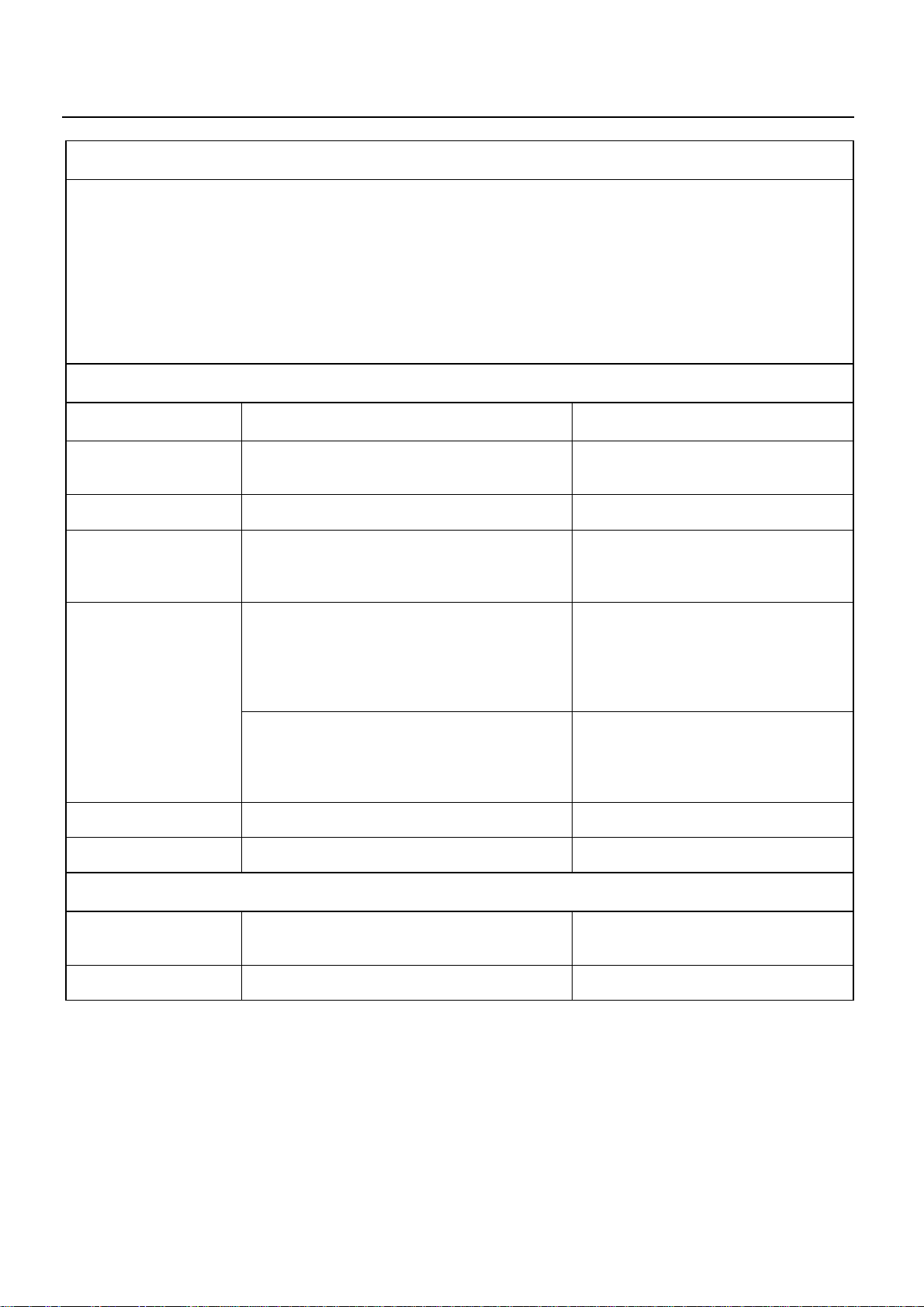
1.HARD STARTING
1. STARTER INOPERATIVE
Checkpoint Possible cause Correction
Battery
Fusible link Fusible link shorted Replace the fusible link
Starter switch Defective starter switch or starter relay Replace the starter switch or the
Loose battery cable terminal poor
connections due to rusting
Battery discharged or weak Recharge or replace the battery
Fan belt loose or broken Adjust or replace the fan belt
Defective magnetic switch or starter relay Repair or replace the magnetic switchStarter motor
Defective starter motor Repair or replace the starter motor
Clean and/or retighten the battery
cable terminal
Starter relay
2. STARTER MOTOR OPERATES BUT ENGINE DOES NOT TURN OVER
Battery
Loose battery cable terminal Clean and/or retighten the battery
cable terminal
Poor connections due to rusting Recharge or replace the battery
Battery discharged or weak Recharge or replace the battery
Fan belt loose or broken Adjust or replace the fan belt
Starter
Engine Piston, crank bearing seizure, or other
Defective pinion gear Replace the pinion gear
Defective magnetic switch Repair or replace the magnetic switch
Brush wear, Weak brush spring Replace the brush and/or the brush
damage
spring
Repair or replace the related parts
Page 8

00 – 4 SERVICE INFORMATION
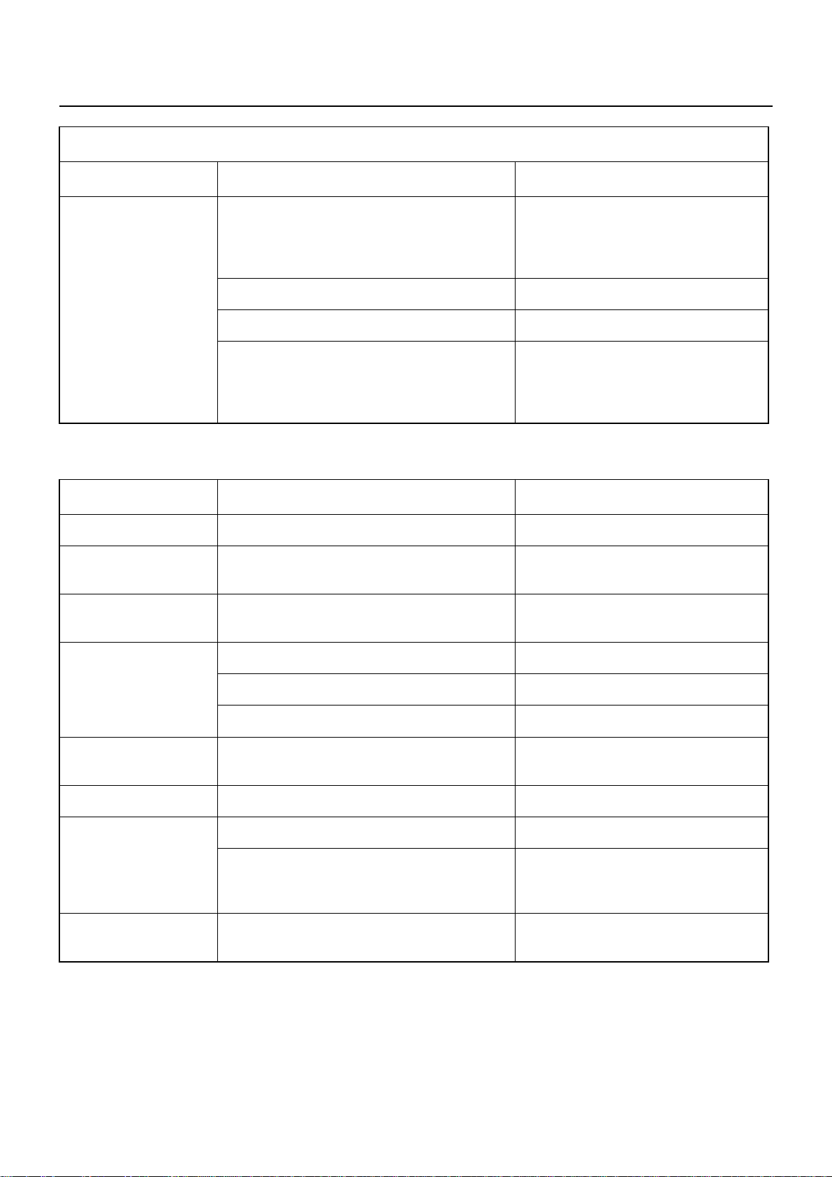
3. ENGINE TURNS OVER BUT DOES NOT START
Checkpoint Possible cause Correction
Engine stop
mechanism
Defective fuel cut solenoid valve Replace the fuel cut solenoid valve
FUEL IS NOT BEING DELIVERED TO THE INJECTION PUMP
Fuel Fuel tank is empty Fill the fuel tank
Fuel piping Clogged or damaged fuel lines. Loose fuel
line connection
Fuel filter
Fuel system Air in the fuel system Bleed the air from the fuel system
Fuel feed pump Defective feed pump Repair or replace the feed pump
Fuel filter overflow valve does not close Repair or replace the fuel filter
Clogged fuel filter element Replace the fuel filter element or the
Repair or replace the fuel lines
Retighten the fuel line connection
overflow valve
filter cartridge
FUEL IS BEING DELIVERED TO THE INJECTION PUMP
Fuel
Use of the wrong fuel Use the correct fuel
Water particles in the fuel Change the fuel
Fuel system
Injection pump
Air in the injection pump Bleed the air from the fuel system
Injection nozzle stickingInjection nozzle
Injection nozzle injection starting pressure
too low
Improper spray condition
Defective fuel injection nozzle resulting in the
fuel drippage after fuel injection
Defective injection pump control rack
operation
Injection pump plunger worn or stuck Replace the injection pump plunger
Injection pump drive shaft seizure or other
damage
Injection pump governor spring seizure Replace the injection pump governor
Adjust or replace the injection nozzle
Replace the delivery valve
Repair or replace the injection pump
control rack
assembly
Replace the injection drive shaft
spring
Page 9
SERVICE INFORMATION 00 – 5
4. QUICK-ON START SYSTEM
PREPARATION
1 Disconnect the thermoswitch connector.
2. Determine whether or not the glow plugs are receiving power.
a) Make sure that the starter switch is “OFF”.
b) Connect a voltmeter between one of the glow plugs and the cylinder wall.
c) Move the starter switch to the “ON” position.
The voltmeter needle will show the souse voltage (12V) if the glow plugs are receiving power.
If the voltmeter needle does not move, the glow plugs are not receiving power.
3. Perform the troubleshooting procedure.
GLOW PLUGS ARE RECEIVING POWER
Checkpoint Possible cause Correction
Glow plug indicator
light does not turn on
Quick-on start timer Defective quick-on start timer Replace the quick-on start timer
Glow plug indicator
light turns on the 0.3
seconds
Glow plug indicator
light turns on for 3.5
seconds
Thermoswitch Defective thermoswitch Replace the thermoswitch
Glow plug continuity No glow plug continuity Replace the glow plugs
Defective indicator light bulb Replace the indicator light bulb
Defective quick-on start timer Replace the quick-on start timer
Return the starter switch to the “ON” position
from the “START” position after the engine
starts if the glow plug relay remains on less
than 14 seconds, the quick-on start timer is
defective
Move the starter switch from the “OFF”
position to the “ON” position if the glow plug
relay remains on less than 14 seconds, the
quick-on start timer is defective
Replace the quick-on start timer
Replace the quick-on start timer
GLOW PLUGS ARE NOT RECEIVING POWER
Glow plug indicator
light does not turn on
Quick-on start timer Defective quick-on start timer Replace the quick-on start timer
Broken indicator light fuse Replace the fuse
Page 10
00 – 6 SERVICE INFORMATION
GLOW PLUGS ARE NOT RECEIVING POWER (Cont’d)
Checkpoint Possible cause Correction
Glow plug indicator
light turns on for 3.5
seconds
Defective glow plug relay
The glow plug relay does not turn on after the
starter switch is moved from the “OFF”
position to the “ON” position
Defective quick-on start timer Replace the quick-on start timer
Defective glow plug relay wiring harness Repair or replace the wiring harness
Defective fusible link or wiring harness
The glow plug relay turns on when the starter
switch is moved from the “OFF” position to
the “ON” position
Replace the glow plug relay
Replace the fusible link or the wiring
harness
2. UNSTABLE IDLING
Checkpoint Possible cause Correction
Idling system Idling improperly adjusted Adjust the idling
Fast idling speed Defective fast idling speed control device Repair or replace the fast idling speed
control device
Accelerator control
system
Accelerator control system improperly
adjusted
Adjust the accelerator control system
Fuel system
Fuel filter Clogged fuel filter element Replace the fuel filter element or the
Fuel feed pump Defective fuel feed pump Repair or replace the fuel feed pump
Injection pump Defective delivery valve resulting in fuel
Fuel system leakage or blockage Repair or replace the fuel system
Air in the fuel system Bleed the air from the fuel system
Water particles in the fuel system Change the fuel
fuel filter cartridge
Injection nozzle sticking Replace the injection nozzleInjection nozzle
Injection nozzle injection starting pressure
too low
Improper spray condition
drippage after fuel injection
Adjust or replace the injection nozzle
Replace the delivery valve
Page 11

SERVICE INFORMATION 00 – 7
Checkpoint Possible cause Correction
Injection pump
(Cont’d)
Valve clearance Valve clearance improperly adjusted Adjust the valve clearance
Compression pressure Blown out cylinder head gasket. Worn
Injection timing improperly adjusted Adjust the injection timing
Insufficient injection volume Adjust the injection volume
Defective idle spring Replace the idle spring
Defective governor lever operation Repair or replace the governor lever
Regulator valve improperly adjustment Adjust or replace the regulator valve
Broken plunger spring Replace the plunger spring
Worn plunger Replace the plunger assembly
Worn cam disc Replace the cam disc
Replace the related parts
cylinder liner.
Piston ring sticking
3. INSUFFICIENT POWER
Checkpoint Possible cause Correction
Air cleaner Clogged air cleaner element Clean or replace the air cleaner
element
Fuel Water particle in the fuel Replace fuel
Fuel filter Clogged fuel filter element Replace the fuel filter element or the
fuel filter cartridge
Fuel feed pump Defective fuel feed pump Repair or replace the fuel feed pump
Injection nozzle sticking Replace the injection nozzleInjection nozzle
Injection nozzle injection starting pressure
too low
Improper spray condition
Fuel injection pipes Fuel injection pipes damaged or obstructed Replace the fuel injection pipes
Adjust or replace the injection nozzle
Page 12

00 – 8 SERVICE INFORMATION
Checkpoint Possible cause Correction
Injection pump
Compression pressure Blown out cylinder head gasket. Worn
Valve clearance Valve clearance improperly adjusted Adjust the valve clearance
Valve spring Valve spring weak or broken Replace the valve spring
Defective regulating valve Repair or replace the regulating valve
Defective delivery valve Replace the delivery valve
Defective timer Repair or replace the timer
Worn cam disc Replace the cam disc
Improper control lever operation Adjust or replace the control lever
Defective injection timing Adjust the injection timing
Repair or replace the injection pump
timer
Weak governor spring Replace the governor spring
Worn plunger Replace the plunger assembly
Replace the related parts
cylinder liner.
Piston ring sticking
Exhaust system Exhaust pipe clogged Clean the exhaust pipe
Full load adjusting
screw seal
Open and improperly set adjusting screw
seal
Adjust and reseal the adjusting screw
Page 13

SERVICE INFORMATION 00 – 9
4. EXCESSIVE FUEL CONSUMPTION
Checkpoint Possible cause Correction
Fuel system Fuel leakage Repair or replace the fuel system
related parts
Air cleaner Clogged air cleaner element Clean or replace the air cleaner
element
Idling speed Poorly adjusted idling speed Adjust the idling speed
Injection nozzle Injection nozzle injection starting pressure
too low
Improper spray condition
Fuel injection timing Fuel injection timing improperly Adjust the fuel injection timing
Injection pump Defective Delivery valve resulting is fuel
drippage after fuel injection
Valve clearance Valve clearance improperly adjusted Adjust the valve clearance
Compression pressure Blown out cylinder head gasket. Worn
cylinder liner.
Piston ring sticking
Valve spring Valve spring weak or broken Replace the valve spring
Adjust or replace the injection nozzle
Replace the delivery valve
Replace the related parts
5. EXCESSIVE OIL CONSUMPTION
Checkpoint Possible cause Correction
Engine oil Engine oil unsuitable
Too much engine oil
Replace the engine oil
Correct the engine oil level
Oil seal and gasket Oil leakage from the oil seal and/or the
gasket
Air breather Clogged air breather Clean the air breather
Intake and exhaust
valve
Worn valve stems and valve guides Replace the intake and exhaust
Replace the oil seal and/or the gasket
valves and the valve guides
Page 14

00 – 10 SERVICE INFORMATION
6. OVERHEATING
Checkpoint Possible cause Correction
Cooling water Insufficient cooling water Replenish the cooling water
Fan clutch Oil leakage from the fan clutch Replace the fan clutch
Fan belt Fan belt loose or cracked causing slippage Replace the fan belt
Radiator Defective radiator cap or clogged radiator
core
Water pump Defective water pump Repair or replace the water pump
Cylinder head and
cylinder body sealing
cap
Thermostat Defective thermostat Replace the thermostat
Cooling system Cooling system clogged by foreign material Clean the foreign material from the
Fuel injection timing Fuel injection timing improperly adjusted Adjust the fuel injection timing
Defective sealing cap resulting in water
leakage
Replace the radiator cap or clean the
radiator core
Replace the sealing cap
cooling system
7. WHITE EXHAUST SMOKE
Checkpoint Possible cause Correction
Cooling water Insufficient cooling water Replace the cooling water
Fuel Water particles in the fuel Replace the fuel
Fuel injection timing Delayed fuel injection timing Adjust the fuel injection timing
Compression pressure Blown out cylinder head gasket. Worn
cylinder liner.
Piston ring sticking
Inlet and exhaust valve
Valves seals
Defective valve seals.
Worn valves stems and valve guides
Replace the related parts
Replace the valve seals, the valves,
and the valve guides
Page 15

SERVICE INFORMATION 00 – 11
8. DARK EXHAUST SMOKE
Checkpoint Possible cause Correction
Air cleaner Clogged air cleaner element Clean or replace the air cleaner
element
Injection nozzle Injection nozzle injection starting pressure
too low
Improper spray condition
Fuel injection timing Fuel injection timing improperly adjusted Adjust the fuel injection timing
Defective delivery valve resulting in fuel
drippage after fuel injection
Excessive injection volume Adjust the injection volume
Adjust or replace the injection nozzle
Replace the delivery valveInjection pump
9. OIL PRESSURE DOES NOT RISE
Checkpoint Possible cause Correction
Engine oil Improper viscosity engine oil.
Insufficient engine oil
Oil pressure gauge or
unit
Oil pressure indicator
light
Oil filter Clogged oil filter element Replace the oil filter element or the oil
Defective oil pressure gauge or unit
Defective indicator light
Replace the engine oil
Correct the engine oil volume
Repair or replace the oil pressure
gauge or unit
Replace the indicator light
filter cartridge
Relief valve and bypass valve
Rocker arm shaft Worn rocker arm bushing Replace the rocker arm bushing
Camshaft Worn camshaft and camshaft bearing Replace the camshaft and the
Crankshaft and
bearings
Relief valve sticking and/or weak by-pass
valve spring
Clogged oil pump strainer Clean the oil pump strainerOil pump
Worn oil pump related parts Replace the oil pump related parts
Worn crankshaft and bearings Replace the crankshaft and/or the
Replace the relief valve and/or the by-
pass valve spring
camshaft bearing
bearings
Page 16

00 – 12 SERVICE INFORMATION
10. ABNORMAL ENGINE NOISE
1. ENGINE KNOCKING
Check to see that the engine has been thoroughly warmed up before beginning the troubleshooting procedure.
Checkpoint Possible cause Correction
Fuel Fuel unsuitable Replace the fuel
Fuel injection timing Fuel injection timing improperly adjusted Adjust the fuel injection timing
Injection nozzle Improper injection nozzle starting pressure
and spray condition
Compression pressure Blown out head gasket
Broken piston ring
Adjust or replace the injection nozzle
Replace the head gasket or the piston
ring
2. GAS LEAKAGE NOISE
Exhaust pipes Loosely connected exhaust pipes. Broken
exhaust pipes
Injection nozzles
and/or glow plugs
Exhaust manifold Loosely connected exhaust manifold and/or
Cylinder head gasket Damaged cylinder head gasket Replace the cylinder head gasket
Loose injection nozzles and/or glow plugs Replace the washers
glow plugs
Tighten the exhaust pipe connections
Replace the exhaust pipes
Tighten the injection nozzles and/or
the glow plugs
Tighten the exhaust manifold
connections
3. CONTINUOUS NOISE
Fan belt Loose fan belt Readjust the fan belt tension
Cooling fan Loose cooling fan Retighten the cooling fan
Water pump bearing Worn or damaged water pump bearing Replace the water pump bearing
Generator or vacuum
pump
Valve clearance Clearance improperly adjust Adjust the valve clearances
Defective generator or vacuum pump Repair or replace the generator or the
vacuum pump
Page 17

SERVICE INFORMATION 00 – 13
4. SLAPPING NOISE
Checkpoint Possible cause Correction
Valve clearance Valve clearance improperly adjusted Adjust the valve clearance
Rocker arm Damaged rocker arm Replace the rocker arm
Flywheel Loose flywheel bolts Retighten the flywheel bolts
Crankshaft and thrust
bearings
Crankshaft and
connecting rod
bearings
Connecting rod
bushing and piston pin
Piston and cylinder
liner
Worn or damaged crankshaft and/or thrust
bearings
Worn or damaged crankshaft and/or
connecting rod bearings
Worn or damaged connecting rod bushing
and piston pin
Worn or damaged piston and cylinder liner. Replace the piston and the cylinder
Replace the crankshaft and/or the
thrust bearings
Replace the crankshaft and/or the
connecting rod bearings
Replace the connecting rod bushing
and/or the piston pin
liner.
Page 18

00 – 14 SERVICE INFORMATION
11. ENGINE COOLING TROUBLE
Checkpoint Possible cause Correction
Engine overheating
Low coolant level Replenish
Thermo unit faulty Replace
Faulty thermostat Replace
Faulty coolant unit Repair or replace
Clogged radiator Clean or replace
Faulty radiator cap Replace
Low engine oil level or use of improper
engine oil
Damaged cylinder head gasket Replace
Clogged exhaust system Clean exhaust system or replace
Loose fan belt Adjust
Excessive fuel injected Adjust
Improper injection timing Adjust
Replenish or change oil
Replenish
faulty parts
Engine overcooling Faulty thermostat Replace
Faulty thermostat ReplaceToo long engine
warm-up time
Thermo unit faulty Replace
Page 19
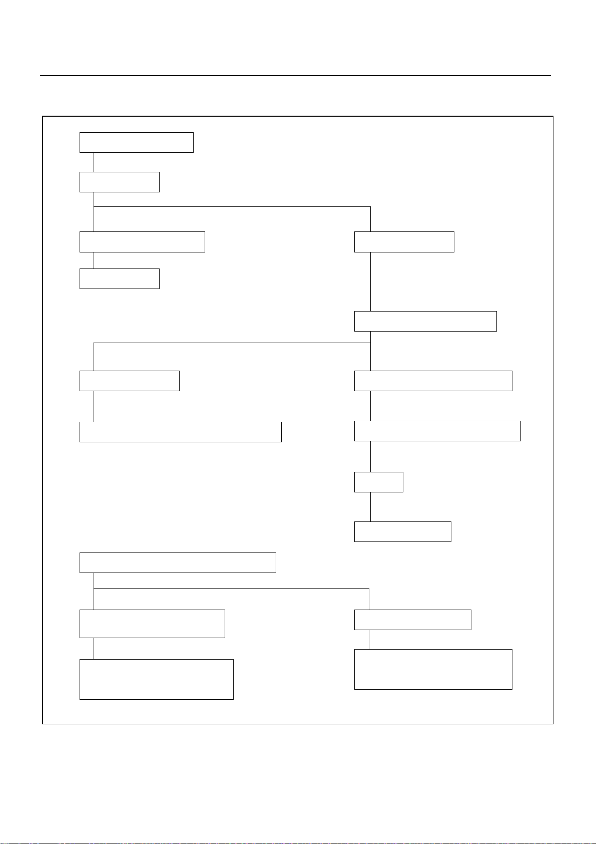
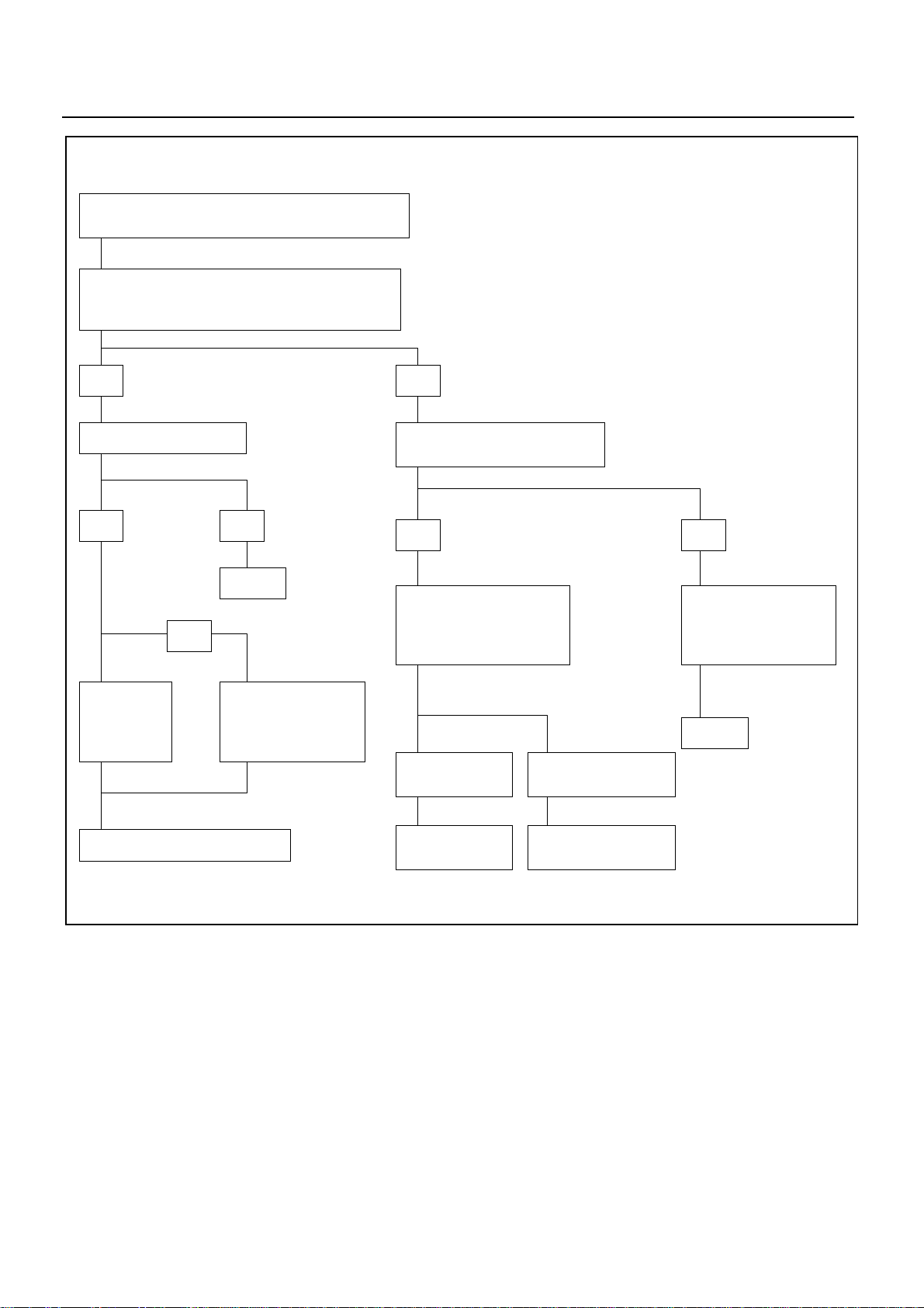
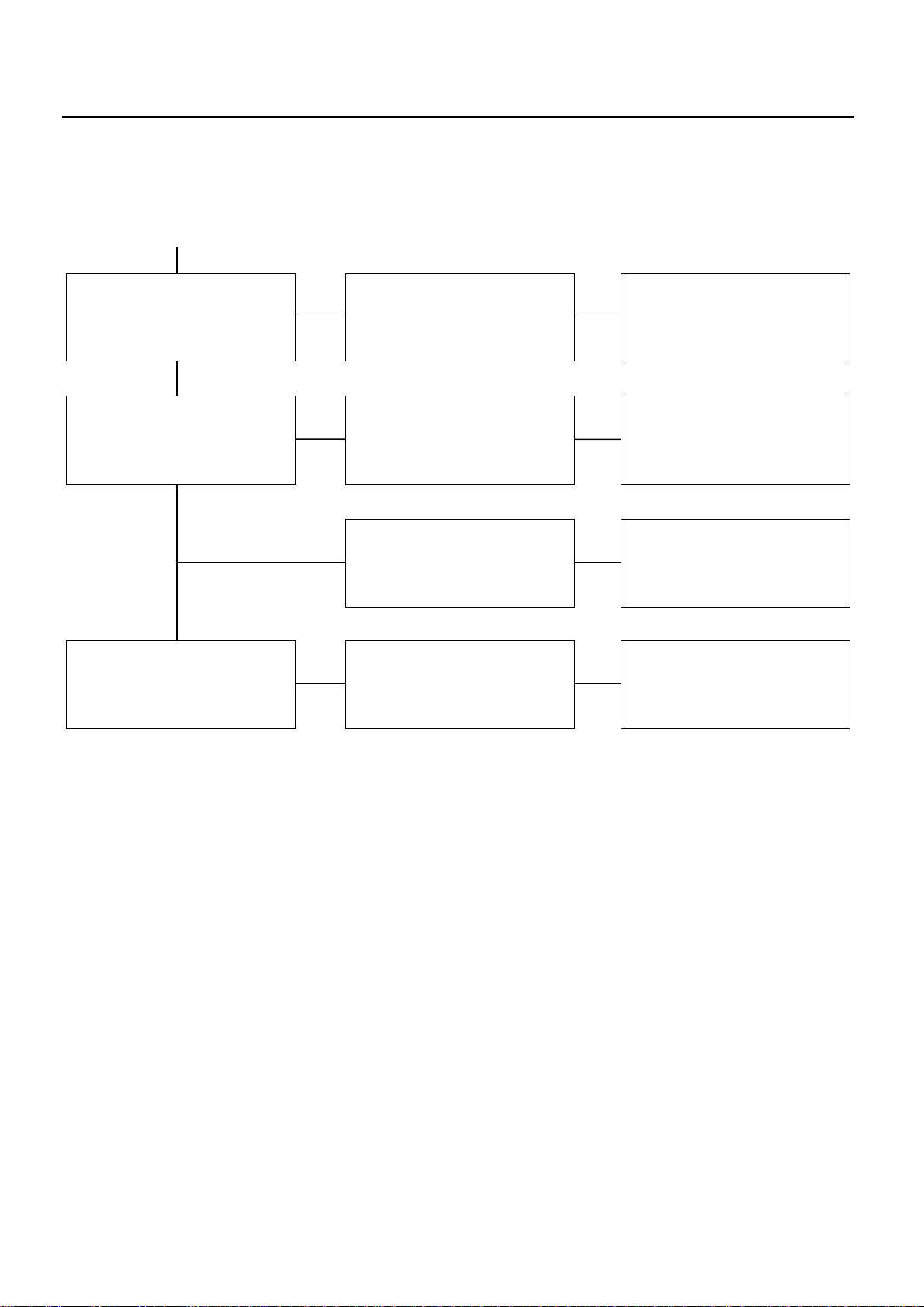
12. ENGINE ELECTRICAL PART TROUBLE
STARTER DOES NOT RUN
CHECK BATTERY
SERVICE INFORMATION 00 – 15
CHARGING FAILURE OR LIFE
CHECK BATTERY
CONNECTION FAILURE
CLEAN BATTERY TERMINALS, AND RECONNECT
BATTERY IS NORMAL
CHECK TERMINAL CONNECTION
TERMINAL CONNECTION IS NORMAL
CHECK STARTER OR STARTER SWITCH
FAILURE
REPAIR OR REPLACE
TURN ON HEAD LAMP AND STARTER SWITCH
HEAD LAMP DOES NOT COME ON
OR IT IS EXTREMELY DARK
a) LACK OF BATTERY CHARGING
b) SHORT-CIRCUIT IN STARTER OIL
c) FAULTY STARTER PARTS
HEAD LAMP ILLUMINATES
a) DISCONNECT STARTER CIRCUIT
b) DISCONNECT STARTER COIL
c) FAULTY STARTER SWITCH
Page 20
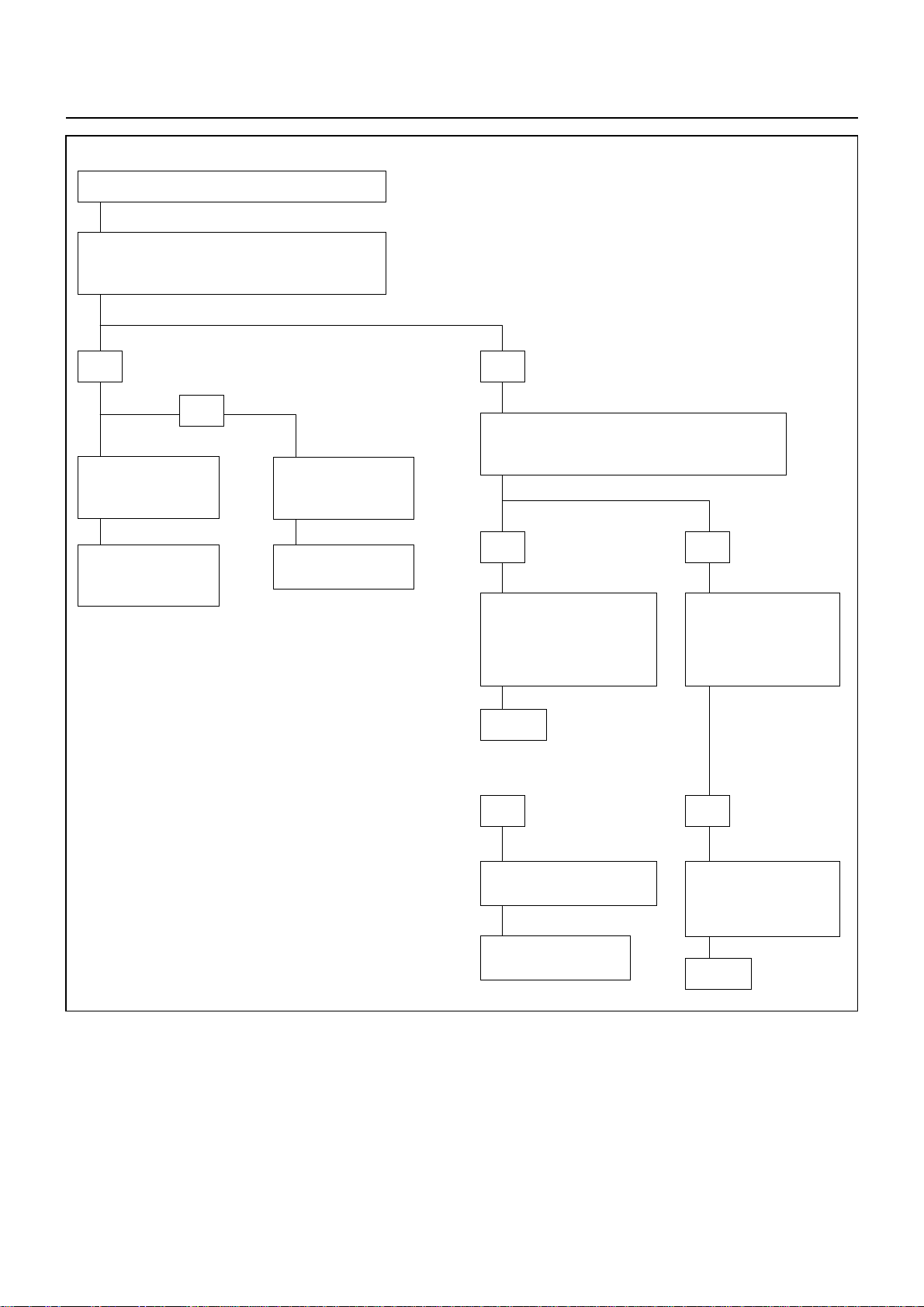
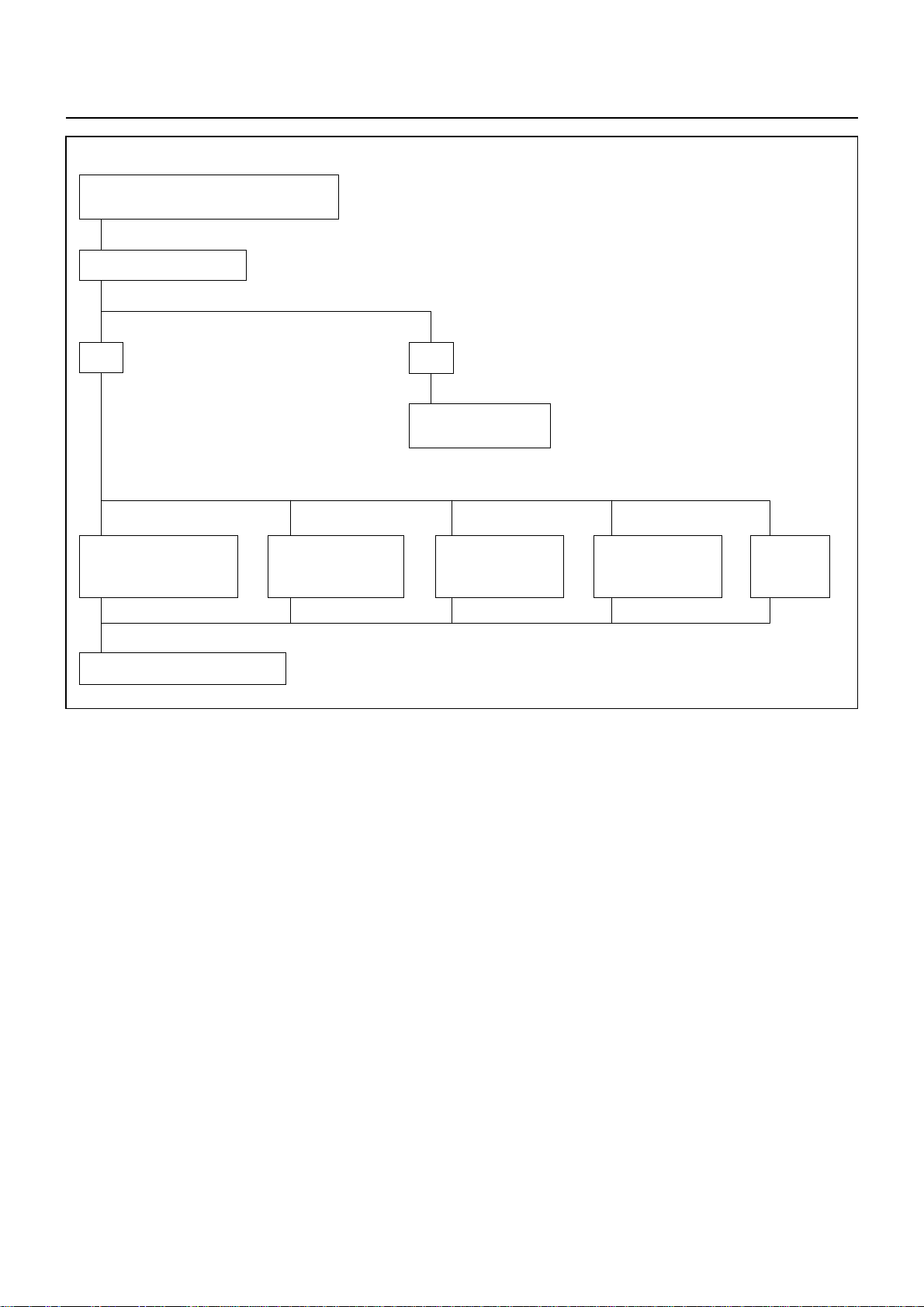
00 – 16 SERVICE INFORMATION
FAULTY MESHING OF PINION AND RING GEAR
CHECK IF BATTERY VOLTAGE IS PRESENT AT
MAGNETIC SWITCH TERMINAL “S” WHEN
STARTER SWITCH IS TURNED TO “START (ST)”
YES
OR
EXTREME WEAR OF
PINION AND RING
GEAR
REPAIR OR REPLACE
STARTER, REPLACE
RING GEAR
STARTER SLIDING
RESISTANCE IS
LARGE
REPAIR OR REPLACE
STARTER
NO
UNDER THIS CONDITION, CHECK IF VOLTAGE
OF CONNECTOR 3BW ON MAGNETIC SWITCH
OF RESTART RELAY IS NORMAL
YES NO
DISCONNECTION OR
FAULTY CONNECTION
BETWEEN STARTER
SWITCH AND MAGNETIC
SWITCH
REPAIR
YES NO
CHECK IF VOLTAGE IS
PRESENT AT WIRING
CONNECTOR 3BW ON
STARTER SWITCH OF
RESTART RELAY
FAULTY CONNECTION OF
STARTER SWITCH
REPLACE STARTER
SWITCH
DISCONNECTION OR
FAULTY CONNECTION
BETWEEN STARTER
SWITCH AND BATTERY
REPAIR
Page 21
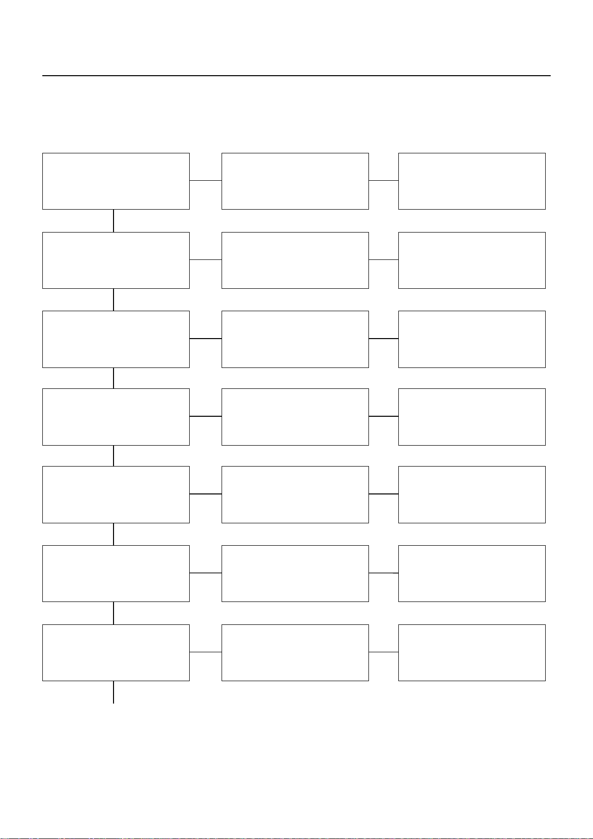
MAGNETIC SWITCH DOES NOT OPERATE THOUGH
STARTER SWITCH IS TURNED TO “START (ST)”
CHECK IF VOLTAGE IS PRESENT AT MAGNETIC
SWITCH TERMINAL “S” WHEN STARTER SWITCH IS
TURNED TO “START (ST)”
SERVICE INFORMATION 00 – 17
YES
YES
YES
CHECK GROUND CABLE
YES NO
REPAIR
OR
PINION
SLIDING
PART DOES
NOT MOVE
MAGNETIC SWITCH
OR COIL IS
DISCONNECTED OR
BURNED OUT
NO
CHECK IF INDICATOR LAMP ON
METER COMES ON NORMALLY
YES NO
CHECK CONTINUITY
STARTER SWITCH AND
MAGNETIC SWITCH
TERMINAL “S”
CHECK STARTER
RELAY
FAULTY CONNECTION
OR STARTER SWITCH
DISCONNECTION OR
FAULTY CONNECTION
BETWEEN BATTERY
AND STARTER SWITCH
REPAIR
REPAIR OR REPLACE STARTER
CHECK CLUTCH
START
REPLACE STARTER
SWITCH
Page 22
00 – 18 SERVICE INFORMATION
PINION MESHES WITH RING GEAR BUT
ENGINE DOES NOT RUN
CHECK GROUND CABLE
YES
FAULTY CONNECTION
OF BRUSH AND
COMMUTATOR
REPAIR OR REPLACE STARTER
BURNED-OUT
MAGNETIC
STARTER SWITCH
NO
REPAIR OR REPLACE
GROUND CABLE
DISCONNECTION
OR DAMAGE OF
FIELD COIL
DISCONNECTION
OR DAMAGED OF
ARMATURE COIL
SLIP OF
PINION
CLUTCH
Page 23
SERVICE INFORMATION 00 – 19
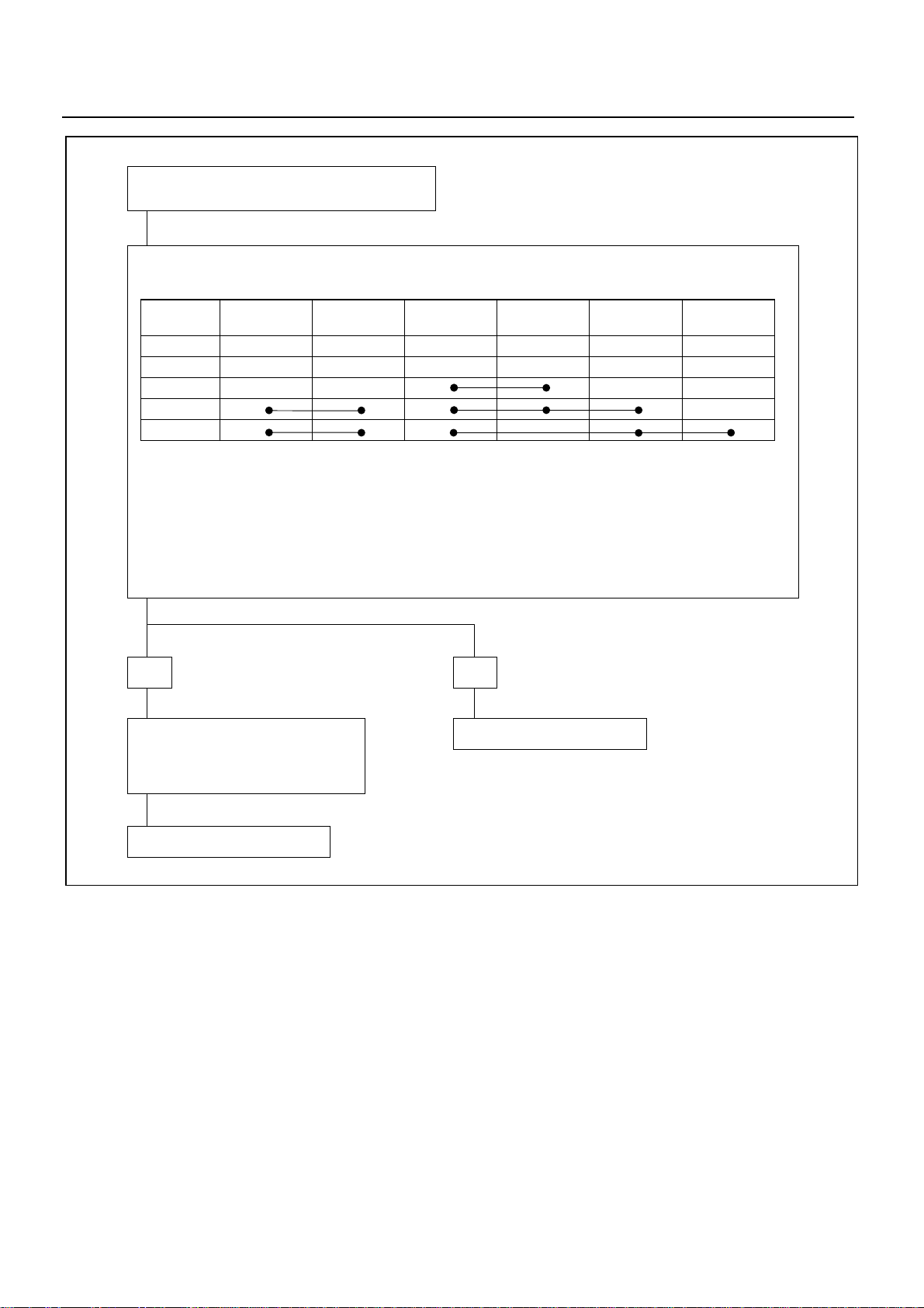
STARTER DOES NOT STOP THOUGH STARTER
SWITCH IS RETURNED TO “ON” FROM “START”
DISCONNECTED STARTER SWITCH WIRING CONNECTOR, AND CHECK STARTER SWITCH OPERATION.
KEY
POSITION
LOCK
OFF
ACC
ON
START
THERE MUST BE NO CONTINUITY EXCEPT ABOVE LINES.
YES
MAGNETIC SWITCH CONTACTS ARE
FUSED AND NOT MOVED, OR A
RETURN SPRING IS BROKEN OR
DETERIORATED
BATTERY
B1
IGNITION
IG1
BATTERYB2ACCESSORIES
ACC
IGNITION
NO
REPLACE STARTER SWITCH
IG2
STARTER
ST
REPLACE MAGNETIC SWITCH
Page 24
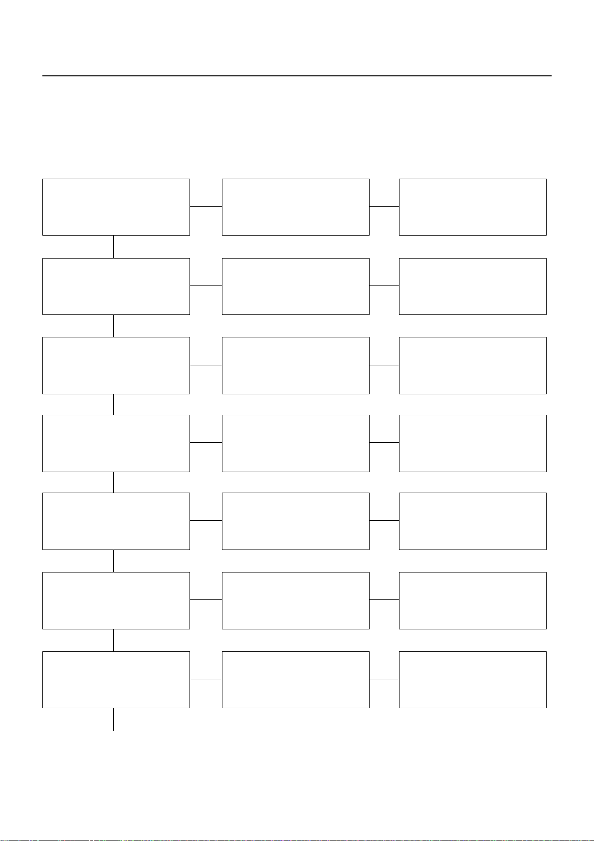
00 – 20 SERVICE INFORMATION
1) ENGINE HAS LESS THAN NORMAL POWER
Checkpoint Trouble Cause Countermeasure
13. TURBOCHARGER
Air cleaner Restricted Clean or replace
OKOK
Intake pipe and hose Restricted Clean or replace
OK
Compressor/Intake manifold Loose (Leaking) Repair
OK
Exhaust manifold/turbine inlet Loose (Leaking) Repair
OK
NG
NG
NG
NG
NG
Exhaust piping and silencers Restricted Clean or replace
OK
Air breather Restricted Clean or replace
OK
Boost compensator
(Injection pump)
Continued on the next page
NG
NG
Defective Repair or replace
Page 25
Checkpoint Trouble Cause Countermeasure
Continued from the previous page
OK
SERVICE INFORMATION 00 – 21
Compressor wheel Impact damage Replace
OKOK
Turbine wheel Impact damage Replace
OK
Rotating assembly Dragging or seized Replace
NG
NG
NG
Carbon build-up Replace
NG
Page 26

00 – 22 SERVICE INFORMATION
Checkpoint Trouble Cause Countermeasure
2) BLUE OR BLACK SMOKE
Air cleaner or intercooler Restricted Clean, repair, or replace
OKOK
Turbocharger oil seal Leakage Replace
OK
Turbocharger oil drain pipe Restricted Repair or replace
OK
Air breather Restricted Clean
OK
NG
NG
NG
NG
Boost compensator
(Injection pump)
OK
Compressor wheel Impact damage Replace
OK
Turbine wheel Impact damage Replace
Continued on the next page
NG
Defective Repair or replace
NG
NG
Page 27

Checkpoint Trouble Cause Countermeasure
Continued from the previous page
OK
SERVICE INFORMATION 00 – 23
Center housing oil drain passage Restricted Clean or replace
NG
Page 28
00 – 24 SERVICE INFORMATION
Checkpoint Trouble Cause Countermeasure
3) EXCESSIVE OIL CONSUMPTION
Air breather Restricted Clean
OKOK
Boost compensator
(Injection pump)
OK
Turbocharger oil seal Leakage Replace
OK
Turbocharger oil drain pipe Restricted Clean or replace
OK
NG
NG
Defective Repair or replace
NG
NG
NG
Turbine wheel Impact damage Replace
OK
Compressor wheel Impact damage Replace
OK
Oil pressure Excessive Repair
Continued on the next page
NG
NG
Page 29

Checkpoint Trouble Cause Countermeasure
Continued from the previous page
OK
SERVICE INFORMATION 00 – 25
Center housing oil drain passage
NG
Restricted Clean or replace
Page 30

00 – 26 SERVICE INFORMATION
4) EXCESSIVE TURBOCHARGER NOISE
Checkpoint Trouble Cause Countermeasure
Intake and exhaust
system joints
OKOK
Intake and exhaust system
gaskets
OK
Turbocharger rotating parts Rough rotation Replace
Compressor wheel
NG
NG
NG
NG
Restricted Repair
Damaged Replace
Rubbing against housing Repair or replace
OK
Turbine wheel
Continued on the next page
NG
NG
NG
NG
Damaged Replace
Rubbing against housing Repair or replace
Damaged Replace
Carbon deposits Clean or replace
Page 31

Checkpoint Trouble Cause Countermeasure
Continued from the previous page
OK
SERVICE INFORMATION 00 – 27
Oil level Too low Correct
OK
Turbocharger oil feed pipe Restricted Repair or replace
OK
Turbine housing Carbon deposits Clean
OK
NG
NG
Contaminated Replace oil
NG
NG
NG
Compressor housing Dirty Clean
OK
Turbine shaft bearings Worn Replace
NG
Page 32

00 – 28 SERVICE INFORMATION
5) EXCESSIVE ROTATING PART WEAR
Checkpoint Trouble Cause Countermeasure
Engine oil Contaminated Change
OK
Turbocharger oil feed pipe Restricted Clean or replace
OK
Turbocharger oil seal Defective Replace
OK
NG
NG
Wrong grade or type Change
NG
NG
Center housing oil
drain passage
OK
Turbine shaft Oil sludge and coking Replace
OK
Engine lubrication system Inadequate oil supply Correct
NG
Restricted Clean or replace
NG
NG
Page 33

LUBRICATION CHART
4JB1, 4JB1TC, 4JG2, Oil Filter & Oil Cooler
SERVICE INFORMATION 00 – 29
kPa (Kg/cm2/psi)
!
Oil filter relief valve opening pressure : 559 - 0618 (5.7 - 6.3/81 - 90)
"
Oil cooler safety valve opening pressure : 314 - 373 (3.2 - 3.8/46 - 54)
#
Oil filter safety valve opening pressure : 78 - 118 (0.8 - 1.2/11 - 19)
$
Oil pressure switch opening pressure : 29.4 - 49.0 (0.3 - 0.5/4.3 - 7.1)
Lubu Chart 5J.tif
The 4J Series engine lubricating system is a full flow type.
Lubricating oil is pumped from the oil pump to the cylinder body oil gallery through the oil cooler and the oil filter
(replaceable type oil filters have on oil cooler). It is then delivered to the vital parts of the engine from the cylinder
body oil gallery.
Page 34

00 – 30 SERVICE INFORMATION
MAIN DATA AND SPECIFICATIONS
MAIN DATA AND SPECIFICATIONS
Item
Engine type Four-cycle, overhead valve, water cooled
Combustion chamber type Direct injection In direct injection
Cylinder liner type Dry type, chrome plated, stainless steel tube
Timing train system Gear drive Gear and Belt Drive
No. of cylinders - Bore x stroke mm (in) 4 - 93 x 102
No. of piston rings Compression rings: 2 / Oil ring: 1
Total piston displacement cm3 (in3) 2,771 (169.0) 3,059 (186.6)
Compression ratio (to 1) 18.2 (4JB1)
Compression pressure kPa (kg/cm2/psi) 3,038 (31 / 441) 3,334 (34 / 483.8)
Engine weight (Dry) N (kg/lb) Approximately
Fuel injection order 1 - 3 - 4 - 2
Engine Model
4JB1 / 4JB1T / 4JB1TC 4JG2 (G. EXP & EC)
4 - 95.4 x 10⁷
(3.66 x 4.02)
18.1 (4JB1T/4JB1TC)
(For EC 2,363 (24.1 / 531))
2,245 (229 / 505) (4JB1)
2,511 (256 / 564)
(4JB1T/4JB1TC)
(3.76 x 4.21)
20.1
Approximately
2,403 (245 / 540)
Fuel injection timing deg BTDC 14 (4JB1)
BTDC 12 (’91/542A) (4JB1)
BTDC 11 (4JB1T)
BTDC 4 (4JB1TC)
Specified fuel type SAE No. 2 diesel fuel
Idling speed rpm 750 - 790 700 – 740
Valve clearances (At cold): Intake mm(in) 0.40 (0.016)
Exhaust mm(in) 0.40 (0.016)
Valve clearances (At hot): Intake mm(in) 0.45 (0.018)
Exhaust mm(in) 0.45 (0.018)
Intake valves Open at (BTDC) deg 24.5
Close at (ATDC) deg 55.5
Exhaust valves Open at (BTDC) deg 54
Close at (ATDC) deg 26
NOTE: G.EXP : General Export Model
EC : European Countries
Emission Gas Control Standard
’91/542A : Euro 1
’91/542B : Euro 2
ATDC 1 (Belt ’91/542A)
TDC 0° (Belt ’91/542B)
ATDC 2 (Gear ’91/542A)
Page 35

SERVICE INFORMATION 00 – 31
Item
Lubricating system
Lubrication method Pressurized circulation
Specified engine oil (API grade) CC (4JB1)
Oil pump type Gear
Oil filter type Disposable cartridge (Spin-on) Paper element
Oil capacity (Including oil filter)
Oil cooler type Water cooled
Fuel system
Injection pump type Bosch distributor
Governor type Mechanical (Partially variable speed) (For EC Variable speed)
Injection nozzle type Hole Pinttle
Injection nozzle kPa (kg/cm2/psi)
opening pressure
Engine Model
lit (US/UK gal) 6.6 - 7.1 (1.74 - 1.87/2.62 - 2.82)
4JB1 / 4JB1T / 4JB1TC 4JG2 (G. EXP & EC)
CC
CD (4JB1T/4JB1TC)
(For EC 6.2 - 8.2 (2.17 - 1.64 / 1.36 - 1.80))
18,142 (185 / 2,631)
(4JB1/4JB1T)
14,710 (150/2,133)
1st: 19,500 (199 / 2,830)
2nd: 26,500 (270 / 3,840)
(4JB1TC)
Main fuel filter type Cartridge paper element and water separator
Air cleaner type Dry paper element
Generator capacity V-A (W) 12 - 40 (480) and 12 - 50 (600) 12 - 50 (600)
(For EC 12 - 60 (720))
Starter motor output V-kW 12 - 2.0 and 12 - 2.2 12 - 2.2
(For EC 12 - 2.0)
Turbocharger IHI RHB5 (4JB1T)
IHI RHF4 (4JB1TC)
Page 36

00 – 32 SERVICE INFORMATION
Engine Cooling
Cooling system
Radiator
Heat radiation capacity kcal/h
Heat radiation area m
Front area m
2
(ft2)
2
(ft2)
Dry weight N (Kg/lb)
Radiator cap
Valve opening pressure kPa (Kg/cm
2
/psi)
Coolant capacity lit (Imp.qt./US qt.)
88.2 - 116.7 (0.899 - 1.199/12.78 - 17.05)
Coolant forced circulation
(2 tube in row) Tube type Corrugated
71400
11.78 (126.8)
0.216 (2.325)
105 (10.7/23.6)
3.1 (2.73/3.28)
(For EC 5.8 (5.1/6.13))
Coolant pump
Pulley type
Pulley ratio
Thermostat type
Centrifugal impeller type
1.2
wax pellet with jiggle valve.
Without jiggle valve (Thailand only)
Valve opening °C (°F)
Valve full open °C (°F)
82 (180)
95 (203)
Coolant total capacity Iit (Imp.qt./US qt.) 10 (8.80/10.57) (For EC 7.3 (6.42/7.71))
Starting System
Manufacturer DENSO
Engine Model 4JB1 / 4JB1T / 4JB1TC 4JG2 (G.EXP & EC)
Rating
Voltage V 12
Output kW 2.0 2.2
Time Sec 30
Number of tooth of pinion 9
Rotating direction (as viewed from pinion) Clockwise
Weight (approx.) kg 4.6 5.4
No-load characteristics
Voltage/current V/A
Speed rpm
11.5/100 or less
3700 or more
Load characteristics
Voltage/current V/A
Torque N•m(Kg•m/lb•ft)
7.5/500 or less
13.7 (1.4/10.1)
Speed rpm 1200 or more 1400 or more
Locking characteristics
Voltage/current V/A
Torque N•m(Kg•m/lb•ft)
2.4/800 or less
18 (1.8/13) or more
2.0/850 or less
16 (1.6/12) or more
Page 37

SERVICE INFORMATION 00 – 33
Charging System
Manufacturer HITACHI LR150-449B DENSO
Rated voltage V 12 12
Rated output A 50 40
Rotating direction
(As viewed from pulley)
Pulley effective diameter mm (in) 80 (3.15) 82 (3.23)
Weight (with pump) kg (lb) 6.0 (13.27)
Clockwise Clockwise
6.7 (14.77)
4JB1TC for G.E
4JB1TC for EC
4JB1TC for Thailand
Page 38

00 – 34 SERVICE INFORMATION
SERVICE STANDARD
Engine Mechanical
Parts Items
Cylinder
Head
Valve
Spring
Cylinder head deck, and
exhaust manifold mating
surface for flatness
Cylinder head height 92.0 (3.622) 91.55 (3.6043)
Cylinder Head Lower Face
Warpage.
Manifold Warpage.
Hot plug sinking
Hot plug exert pressure
Free height
Squareness
Service standard Service limit
4JG2
0.05 (0.002) or less 0.2 (0.0079)
0.05 (0.002)or less
0.05 (0.002) or less
4,500 – 5,500 kg
(9922.5 - 12127.5 lbs)
48.0 (1.891)
4JB1 / 4JB1T /
4JB1TC
-
-
4JG2
0.20 (0.008)
0.20 (0.008)
0.02 (0.0008)
-
47.10 (1.856)
1.7 (0.067)
4JB1 / 4JB1T /
4JB1TC
mm (in)
Remarks
Cannot be
Reground
Valve
and
Valve
Guide
Spring tension N (kg/lb)
Diameter Valve Stem
IN
EX
Valve and valve guide
clearance IN
EX
Valve guide upper end
height (Measured from the
Cylinder head upper face)
Valve guide margin
Valve thickness IN
EX
Valve seat contact surface
angle
296 (30.2/66.4)
7.946 - 7.961
(0.3128 - 0.3134)
7.921 - 7.936
(0.3118 - 0.3124)
0.039 - 0.069
(0.0015 - 0.0027)
0.064 - 0.096
(0.0025 - 0.0038)
13.0 (0.512)
1.1 (0.0433)
1.41 (0.0556)
1.39 (0.0547)
1.79 (0.0705)
1.83 (0.0720)
45°
257.9 (26.3/57.9) At installed
7.880 (0.3102)
7.850 (0.3090)
0.200 (0.0079)
0.250 (0.0098)
-
1.6 (0.0630)
1.1 (0.0433)
1.1 (0.0433)
1.5 (0.06)
1.5 (0.06)
height
38.9 (1.531)
Valve seat contact width
IN
EX
1.7 (0.0669)
2.0 (0.0787)
2.2 (0.0866)
2.5 (0.0984)
Page 39

SERVICE INFORMATION 00 – 35
Service standard Service limit
Parts Items
4JG2
Push rod Curvature - 0.4 (0.0157) or less
4JB1 / 4JB1T /
4JB1TC
4JG2
4JB1 / 4JB1T /
4JB1TC
mm (in)
Remarks
Camshaft End play
Cam lobe height
Journal diameter
Runout
Camshaft bearing inside
diameter
Camshaft oil clearance
Tappet Outside diameter
Oil clearance
(Between tappet and
cylinder body)
Rocker
arm
Assembly
Rocker shaft outside
diameter
Rocker arm inside
diameter
Oil clearance
(Between rocker arm and
rocker shaft)
0.08 (0.0031)
42.02 (1.6543)
49.945 - 49.975(1.9663-1.9675)
0.02 (0.0008) or less
50.000 - 50.030
(1.9685 - 1.9697)
0.025 - 0.085
(0.0098 - 0.00334)
12.97 - 12.99 (0.5106 - 0.5114)
0.03 (0.0118)
18.98 - 19.00
(0.7472 - 0.7480)
19.036 - 19.060
(0.7494 - 0.7504)
0.06 - 0.08
(0.00235 - 0.00315)
0.2 (0.0079)
41.65 (1.6397)
49.60 (1.9527)
0.10 (0.0039)
50.08(1.9716)
0.12 (0.0047)
12.95 (0.5098)
0.10 (0.0039)
18.90 (0.7440)
19.10 (0.7520)
0.10 (0.004)
Rocker shaft runout
Oil clearance
Body and gear
Body cover and gear 0.06 (0.0024) 0.02 - 0.07
Crankshaft Thrust clearance 0.10 (0.0039) 0.30 (0.018)
Main bearing clearance
(Between main bearing
and Crankshaft)
Crankshaft runout
Main journal diameter
Crankshaft pin diameter
Crankshaft Journal and
Crank Pin uneven wear
Crank Pin and Bearing
Clearance.
0.14 (0.0055) 0.13 - 0.14
0.031-0.063
(0.0012-0.0025)
0.05 (0.00197) or less
69.917 - 69.932 (2.7526 - 2.7532)
52.915 - 52.930 (2.0833 - 2.0839)
0.05 (0.002) or less
0.029 - 0.066 (0.0011 - 0.0026)
-
(0.0051-0.0055)
(0.0008-0.0028)
0.035-0.080
(0.0014-0.0032)
0.2 (0.0079) or less
0.20 (0.0079) 0.15 (0.0059)Oil pump
0.15 (0.0059)
0.11
(0.0043)
0.08 (0.0031)
69.91 (2.7524)
52.90 (2.0827)
0.08 (0.003)
0.100 (0.0039)
Page 40

00 – 36 SERVICE INFORMATION
Parts Items
Service standard Service limit
4JG2
4JB1 / 4JB1T /
4JB1TC
4JG2
4JB1 / 4JB1T /
4JB1TC
mm (in)
Remarks
Piston
pin,
Piston
ring and
Connecting rod
Piston diameter 95.365 - 95.404
(3.7545-3.9039)
Piston Clearance
(Between piston and
Cylinder liner)
Piston ring gap 1st
Piston ring clearance 1st
0.047 - 0.065
(0.0019-0.0026)
(0.0079 –
2nd
(0.0146 -
Oil
(0.0079 -
(0.0035 -
2nd
(0.002 -
0.20 - 0.35
0.0138)
0.37 - 0.52
0.0205)
0.20 - 0.40
0.00157)
0.09 - 0.13
0.0051)
0.05 - 0.09
0.0035)
92.985 - 93.024
(3.6600-3.6623)
0.025 - 0.045
(0.0010-0.0018)
0.20 - 0.40
(0.0079 –
0.0157)
0.20 - 0.40
(0.0079 -
0.00157)
0.10 - 0.30
(0.0039 -
0.0118)
0.090 - 0.125
(0.0035 -
0.0049)
0.050 - 0.075
(0.0020 -
0.0030)
-Piston,
-
1.5 (0.0591)
1.5 (0.0591)
1.5 (0.0591)
0.15 (0.0059)
Oil 0.03 - 0.07
(0.0012 - 0.0028)
Piston pin diameter 33.995 - 34.000
(1.3384-1.3386)
Fitting interference
(Between connecting
rod and piston pin)
Fitting interference
(Between piston and
piston pin)
Connecting rod
alignment Bend
Twist
Piston pin and Connecting
Rod Bushing Clearance
Connecting rod thrust
clearance
Oil clearance
(Between crank pin and
Connecting rod) 0.0033) 0.0026)
0.029 -0.083 0.029 - 0.066 0.100 (0.0039)
(0.0014 - (0.0011 -
0.008 - 0.020
(0.0003 - 0.0008)
0.002 - 0.015
(0.0001 - 0.0006)
0.08 (0.0031) or less
0.05 (0.0020) or less
0.008 - 0.020
(0.0003 - 0.0008)
0.230 (0.0091)
30.995 - 31.000
(1.2202-1.2204)
0.15 (0.0059)
33.970
(1.3374)
0.05 (0.0020)
0.04 (0.0016)
0.20 (0.0079)
0.15 (0.0059)
0.050 (0.0020)
0.35 (0.0138)
30.970
(1.2190)
Per 100
(3.94)
Per 100
(3.94)
Page 41

Parts Items
SERVICE INFORMATION 00 – 37
Service standard Service limit
4JG2
4JB1 / 4JB1T /
4JB1TC
4JG2
4JB1 / 4JB1T /
4JB1TC
mm (in)
Remarks
Cylinder
Block
Warpage
(Upper surface of the
cylinder block)
Cylinder bore diameter 97.000 - 97.040 95.011 - 95.040
(3.8189 - (3.7406 -
3.8205) 3.7417)
Cylinder liner projection 0.0-0.1
Cylinder liner inside 95.420 - 95.460 93.020 - 93.060
diameter (3.7567 - (3.6622 -
3.7583) 3.6638)
Cylinder liner outside 97.011-97.050 95.011 - 95.050
diameter (3.8193 - (3.7405 -
3.8209) 3.7421)
- 0.20 (0.0079)
(0.00-0.0039)
Page 42

00 – 38 SERVICE INFORMATION
SERVICING
Servicing refers to general maintenance procedures to be
performed by qualified service personnel.
MODEL IDENTIFICATION
Engine Serial Number
The engine number is stamped on the front left hand side
of the cylinder body.
0038-1.tif
AIR CLEANER
Dry Type Paper Element
Element cleaning procedures will vary according to the
condition of the element.
0038-2.tif
Dust fouled Element
Rotate the element with your hand while applying
compressed air to the inside of the element. This will
blow the dust free.
Compressed air pressure kPa (kg/cm
392 - 490 (4 - 5/57 - 71)
CAUTION
Do not bang the element against another object in an
attempt to clean it. Damage to the element will result.
Carbon and Dust Fouled Element
1. Prepare a cleaning solution of Isuzu Genuine Element
Cleaner (Donaldson D1400) diluted with water.
2. Submerge the element in the solution for twenty
minutes.
2
/Psi)
0038-3.tif
Page 43

0039-1.tif
SERVICE INFORMATION 00 – 39
3. Remove the element from the solution and rinse it
well with running water.
Water pressure must not exceed 274 kPa (2.8 kg/cm
/40Psi)
4. Dry the element in a well ventilated area.
An electric fan will hasten drying.
NOTE:
Do not use compressed air or an open flame to dry
the element quickly. Damage to the element will
result. It will usually take two or three days for the
element to dry completely. Therefore, it is a good idea
to have a spare on hand to use in the interim.
2
0039-2.tif
050LX001.tif
LUBRICATING SYSTEM
Main Oil Filter (Cartridge Type Paper Element)
Replacement Procedure
1. Loosen the used oil filter by turning it
counterclockwise with the filter wrench.
2. Clean the oil filter fitting face.
This will allow the new oil filter to seat properly.
3. Apply a light coat of engine oil to the O-ring.
4. Turn in the new oil filter until the filter O-ring is fitted
against the sealing face.
5. Use the filter wrench to turn in the filter an additional 1
and 1/4 turns.
Filter Wrench : 5-8840-0200-0 (89mm/3.5in)
5-8840 0202-0 (106mm/4.2in)
5-8840-2209-0 (100.6mm/4.0in)
6. Check the engine oil level and replenish to the
specified level if required.
Replenishment Engine Oil lit (Imp qt/US qt)
0.7 (0.62/0.74)
0039-4.tif
7. Start the engine and check for oil leakage from the
main oil filter.
Page 44

00 – 40 SERVICE INFORMATION
FUEL SYSTEM
Fuel Filter
Replacement Procedure
1. Loosen the used fuel filter by turning it
counterclockwise with the filter wrench.
Filter Wrench: 5-8840-0253-0 (J-22700)
0040-1.tif
2. Clean the filter cover fitting faces.
This will allow the new fuel filter to seat properly.
0040-2.tif
0040-3.tif
0040-4.tif
3. Turn in the fuel filter until the sealing face comes in
contact.
4. Turn in the fuel filter an additional 2/3 of a turn with a
filter wrench.
Filter Wrench: 5-8840-0253-0 (J-22700)
5. Loosen the bleeder plug on the injection pump
overflow valve.
6. Operate the priming pump until fuel begins to flow
from the fuel filter.
7. Retighten the bleeder plug.
8. Operate the priming pump several times and check
for fuel leakage.
NOTE:
The use of an ISUZU genuine fuel filter is strongly
recommended.
0041-1.tif
Fuel Filter Water Draining Procedure
The indicator light will come on when the water level in
the water separator exceeds the specified level.
Drain the water and foreign material from the water
separator with the following procedure.
Page 45

0041-2.tif
SERVICE INFORMATION 00 – 41
1. Find a safe place to park the vehicle.
2. Open the engine hood and place a container
(Approximately 0.2 liter capacity) at the end of the
vinyl hose beneath the drain plug on the separator.
3. Loosen the drain plug by turning it counterclockwise
(Approximately 5 turns) and operate the priming pump
up and down about 10 times until water is drained
approximately 0.1 liter.
4. After draining, securely tighten the drain plug by
turning it clockwise and operate the priming pump
manually up and down several times.
5. After starting the engine, check to see that there is no
fuel leak from the drain plug. Also check to see that
the fuel filter water indicator light has turned off.
If water separator requires frequent draining, have the
fuel tank drained for removal of water at your Isuzu
Dealer.
Air Bleeding
1. Loosen the bleeder screw on the injection pump
overflow valve.
2. Operate the priming pump until fuel mixed with foam
flows from the bleeder screw.
3. Tighten the bleeder screw.
4. Operate the priming pump several times and check
for fuel leakage.
0041-3.tif
0041-4.tif
0042-1.tif
COOLING SYSTEM
Coolant Level
Check the coolant level and replenish the radiator reserve
tank as necessary.
If the coolant level falls below the “MIN” line, carefully
check the cooling system for leakage. Then add enough
coolant to bring the level up to the “MAX” line.
Engine coolant change procedure
1. To change engine coolant, make sure that the engine
is cool.
WARNING:
When the coolant is heated to a high
temperature, be sure not to loosen or remove
the radiator cap. Otherwi se you might get
scalded by hot vapor or boiling water. To open
the radiator cap, put a piece of thick cloth on the
cap and loosen the cap slowly to reduce the
pressure when the coolant has become cooler.
2 Open radiator cap and drain the cooling system by
loosening the drain valve on the radiator and on the
cylinder body.
Page 46

00 – 42 SERVICE INFORMATION
NOTE:
For best result it is suggested that the engi ne
cooling system be flushed at least once a year.
it is advisable to flush the interior of the cooling
system including the radiator before using antifreeze (ethylene-glycol based).
Replace damaged rubber hoses as the engine
anti-freeze coolant is liabl e t o l eak out even
minor cracks. Isuzu recommends to use lsuzu
genuine anti-freeze (ethylene-glycol based) or
equivalent, for the cooling system and not add
any inhibitors or additives.
CAUTION:
A failure to correctly fill the engine cooling
system in changing or topping up coolant may
sometimes cause the coolant to overflow f r om
the filler neck even before the engine and
radiator are completely full. If the engine runs
under this condition, shortage of coolant may
possibly result in engine overheating. To avoid
such trouble, the following precautions should
be taken in filling the system.
3 To refill engine coolant, pour coolant up to filler neck
using a filling hose which is smaller in outside
diameter of the filler neck.
Othewise air between the filler neck and the filling
hose will block entry, preventing the system from
completely filling up.
4 Keep a filling rate of 9 liter/min. or less. Filling over
this maximum rate may force air inside the engine
and radiator. And also, the coolant overflow will
increase, making it difficult to determine, whether or
not the system is completely full.
5 After filling the system to the full, pull out the filling
hose and check to see if air trapped in the system is
dislodged and the coolant level goes down. Should
the coolant level go down, repeat topping-up until
there is no more drop in the coolant level.
6 After directly filling the radiator, fill the reservoir to the
maximum level.
7 Install and tighten radiator cap and start the engine.
After idling for 2 to 3 minutes, stop the engine and
reopen radiator cap. If the water level is lower,
replenish.
WARNING:
When the coolant is heated to a high
temperature, be sure not to loosen or remove
the radiator cap. Otherwi se you might get
scalded by hot vapor or boiling water. To open
the radiator cap, put a piece of thick cloth on the
cap and loosen the cap slowly to reduce the
pressure when the coolant has become cooler.
8 After tightening radiator cap, warm up the engine at
about 2,000 rpm. Set heater adjustment to the
highest temperature position, and let the coolant
circulate also into heater water system.
9 Check to see the thermostat has opened through the
Page 47

0042-2.tif
0042-3.tif
SERVICE INFORMATION 00 – 43
needle position of water thermomete, conduct a
5 minutes idling again and stop the engine.
10 When the engine has been cooled, check filler neck
for water level and replenish if required. Should
extreme shortage of coolant is found, Check the
coolant system and reservoir tank hose for leakage.
11 Fill the coolant into the reservoir tank up to “MAX”
line.
Cooling System Inspection
Install a radiator filler cap tester to the radiator. Apply testing
pressure to the cooling system to check for leakage.
The testing pressure must not exceed the specified pressure.
Testing Pressure kPa (Kg/cm2/psi)
147 (1.5/21)
Radiator Cap Inspection
The radiator filler cap is designed to maintain coolant
pressure in the cooling system at 1.05 kg/cm
kPa). Check the radiator filler cap with a radiator filler cap
tester. The radiator filler cap must be replaced if it fails to
hold the specified pressure during the test procedure.
Radiator Filler Cap Pressure
Pressure Valve kPa (Kg/cm
Negative Valve (Reference) kPa (Kg/cm2/psi)
88 - 118 (0.9 - 1.2/12.8 - 17.1)
1.0 - 13.9 (0.01 - 0.04/0.14 - 0.57)
2
(15 psi / 103
2
/psi)
0042-4.tif
Thermostat Operating Test
1. Completely submerge the thermostat in water.
2. Heat the water.
Stir the water constantly by suitable wood bar (2) to
avoid direct heat being applied use wood plate (3) to
the thermostat.
3. Check the thermostat initial opening temperature.
Thermostat Initial
Opening Temperature °C (°F)
4. Check the thermostat full opening temperature.
Thermostat Full
Opening Temperature °C (°F)
Valve Lift at Fully Open Position mm (in)
82 (180)
95 (203)
10 (0.39)
Page 48

00 – 44 SERVICE INFORMATION
0043-1.tif
Drive Belt Adjustment
Depress the drive belt mid portion with a 98N (10 kg/22
lb) force.
Drive Belt Deflection mm (in)
10 (0.39)
Check the drive belt for cracking and other damage.
1. Crankshaft damper pulley
2. Generator pulley
3. Cooling fan pulley
4. Oil pump pulley or idler pulley
5. Compressor pulley or idle pulley
Cooling Fan Pulley Drive Belt
Fan belt tension is adjusted by moving the generator.
Depress the drive belt mid portion with a 98N (10 kg/22
lb) force.
1. Crankshaft damper pulley
2. Generator pulley
3. Cooling fan pulley
0043-2.tif
0043-3.tif
0043-4.tif
Compressor Pulley Drive Belt
Move the idler pulley as required to adjust the compressor
drive belt tension.
If the vehicle is equipped with power steering, move the
oil pump as required.
Depress the drive belt mid portion with a 98N (10 kg/22
lb) force.
Belt Deflection mm (in)
14 - 17 (0.55 - 0.67)
1. Crankshaft damper pulley
2. Oil pump pulley or idler pulley
Power Steering Oil Pump Pulley Drive Belt
Move the oil pump as required to adjust the oil pump drive
belt tension.
On air conditioner equipped models, both drive belts
pulley must always be replaced as a set.
Depress the drive belt mid portion with a 98N (10 kg/22
lb) force.
Belt Deflection mm (in)
1. Crankshaft damper pulley
2. Oil pump pulley
3. Compressor pulley or idler pulley
14 - 17 (0.55 - 0.67)
Page 49

SERVICE INFORMATION 00 – 45
ENGINE CONTROL
Idling Speed Inspection
1. Set the vehicle parking brake and choke the drive
wheels.
2. Place the transmission in neutral.
3. Start the engine and allow it to warm up.
4. Disconnect the engine control cable from the control
lever.
5. Set a tachometer to the engine.
6. Check the engine idling speed.
If the engine idling speed is outside the specified
range, it must be adjusted.
Engine Idling Speed rpm
4JB1 / 4JB1T / 4JB1TC 750 - 790
4JG2 700 - 740
Idling Speed Adjustment
0044-1.tif
1. Loosen the idling set bolt lock nut on the injection
pump idling set bolt.
2. Adjust the idling speed to the specified range by
turning the idling set bolt.
3. Lock the idling set bolt with the idling set bolt lock nut.
4. Check that the idling control cable is tight (free of
slack).
If required, remove the slack from the cable.
Accelerator Control Cable Adjustment
1. Loosen the accelerator cable clamp bolt.
2. Check that the idling control knob on the instrument
panel is in the engine idling position.
3. Hold the accelerator lever in the fully closed position
and stretch the control cable in the direction indicated
by the arrow to remove any slack.
Accelerator Pedal Adjustment
1. Loosen the lock nut.
2. Adjust bolt height from floor.
Adjust Bolt Height A mm (in)
18 - 28 (0.71 - 1.1)
0044-2.tif
Page 50

00 – 46 SERVICE INFORMATION
0045-1.tif
1. Hold the accelerator pedal pad securely by hand, and
give it a full stroke.
2. Adjust the stopper bolt so that the clearance between
the pad stopper bolt and the rear side of the pad
becomes the specified length.
0 - 2 (0 - 0.079)
mm (in)
3. Check to see if the accelerator pedal play is in the
range of 5 to 10mm above the pedal pad.
4. Press down on the accelerator pedal fully and check
to see if the engine rotates at its maximum speed with
each of the linkage in the smooth operation.
5. In the operating range of accelerator pedal and the
injection pump lever returns to their respective original
positions without fail.
VALVE CLEARANCE ADJUSTMENT
1. Bring the piston in either the No. 1 cylinder or the No.
4 cylinder to TDC on the compression stroke by
turning the crankshaft until the crankshaft damper
pulley TDC line is aligned with the timing pointer.
0045-2.tif
0045-3.tif
0045-4.tif
2. Check the rocker arm shaft bracket nuts for
looseness.
Tighten any loose rocker arm shaft bracket nuts
before adjusting the valve clearance.
Rocker Arm Shaft
Bracket Nut Torque N∙m (kg∙m/lb∙ft)
54 (5.5/40)
3. Check for play in the No. 1 intake and exhaust valve
push rods.
If the No. 1 cylinder intake and exhaust valve push
rods have play, the No. 1 piston is at TDC on the
compression stroke.
If the No. 1 cylinder intake and exhaust valve push
rods are depressed, the No. 4 piston is at TDC on the
compression stroke.
Page 51

0046-1.tif
SERVICE INFORMATION 00 – 47
Adjust the No. 1 or the No. 4 cylinder valve clearance
while their respective cylinders are at TDC on the
compression stroke.
Valve Clearance (At Cold) mm (in)
0.4 (0.016)
4. Loosen each valve clearance adjusting screw as
shown in the illustration.
5. Insert a feeler gauge of the appropriate thickness
between the rocker arm and the valve stem end.
6. Turn the valve clearance adjusting screw until a slight
drag can be felt on the feeler gauge.
7. Tighten the lock nut securely.
8. Rotate the crankshaft 360°.
9. Realign the crankshaft damper pulley TDC notched
line with the timing pointer.
10. Adjust the clearance for the remaining valves as
shown in the illustration.
0046-2.tif
0046-3.tif
0046-4.tif
INJECTION TIMING ADJUSTMENT
1. Check that the notched line on the injection pump
flange is aligned with the front plate or the timing gear
case notched line.
2. Bring the piston in the No. ! cylinder to TDC 1 on the
compression stroke by turning the crankshaft until the
crankshaft pulley TDC line is aligned with the timing
"
mark
Note:
Check for play in the No. 1 intake and exhaust valve
push rods.
If the No. 1 cylinder intake and exhaust valve push
rods have play, the No. 1 piston is at TDC on the
compression stroke.
.
0046-5.tif
3. Disconnect the injection pipe from the injection pump.
4. Remove one bolt from the distributor head.
5. Insert a screwdriver into a hole in the fast idle lever
and turn the lever to release the W-C.S.D. function. (If
so equipped)
6. Install the static timing gauge
#
.
The probe of the gauge should be depressed inward
approximately 2 mm (0.079 in).
Static Timing Gauge : 5-8840-0145-0 (J-28827)
Page 52

00 – 48 SERVICE INFORMATION
0047-1.tif
0047-2.tif
7. Rotate the crankshaft to bring the piston in the No. 1
cylinder to a point 30 - 40° BTDC.
8. Set the timing gauge needle to zero.
9. Move the crankshaft pulley slightly in both directions
to check that the gauge indication is stable.
10. Turn the crankshaft clockwise and read the gauge
indication when the crankshaft pulley timing mark is
aligned with the pointer.
mm (in)
4JB1 BTDC 14°
4JB1T BTDC 11°
4JB1TC BTDC 4°
4JG2 ATDC 2°
Standard Reading mm (in)
0.5 (0.02)
0047-3.tif
If the injection timing is outside the specified range,
continue with the following steps.
11. Loosen the injection pump fixing nuts and bracket
bolts.
12. Adjust the injection pump setting angle.
When large than
standard value
When smaller than
standard value
Gear drive A B
A : Move the injection pump toward the engine.
B : Move the injection pump away from the engine.
Tighten the pump fixing nut, adjust bolt and pump
distributor head plug to the specified torque.
Pump Fixing Bolt N∙m (kg∙m/lb∙ft)
Adjust Bolt N∙m (kg∙m/lb∙ft)
24 (2.4/17)
19 (1.9/14)
Injection Pump
Distributor Head Plug N∙m (kg∙m/lb∙ft)
17 (1.7/12)
CAUTION
• When installing the distributor head/plug, be sure
to use new copper washer.
Page 53

0048-1.tif
SERVICE INFORMATION 00 – 49
COMPRESSION PRESSURE MEASUREMENT
1. Start the engine and allow it to idle until the coolant
temperature reaches 70 - 80°C (158 - 176°F).
2. Remove the following parts.
* Glow plugs
* Fuel cut solenoid connector
* QOS (Quick-On Start System) fusible link wire at
the connector.
3. Set the adapter and compression gauge to the No. 1
cylinder glow plug hole.
Compression Gauge
(with Adapter): 5-8840-2008-0 (J-29762)
Adapter: 5-8531-7001-0
4. Turn the engine over with the starter motor and take
the compression gauge reading.
Compression Pressure at 200 rpm kPa (Kg/cm
Standard Limit
2
/psi)
0048-2.tif
0048-3.tif
4JB1 3,038 (31/441) 2,157 (22/313)
4JG2 3,334 (34/484) 2,452 (25/356)
5. Repeat the procedure (Steps 3 and 4) for the
remaining cylinders.
If the measured value is less than the specified limit,
refer to “Troubleshooting” in this Manual.
QUICK-ON START II SYSTEM
(4JB1 / 4JB1T / 4JB1TC only)
Quick-On Start System Inspection Procedure
1. Disconnect the thermo-sensor connection on the
thermostat outlet pipe.
2. Turn the starter switch to the “ON” position.
If the Quick-On Start II System is operating properly,
the glow relay will make a clicking sound within 15
seconds after the starter switch is turned on.
3. Measure the glow plug terminal voltage with a circuit
tester immediately after turning the starter switch to
the “ON” position.
Glow Plug Terminal Voltage V
Approx. 11
0048-4.tif
Page 54

00 – 50 SERVICE INFORMATION
0049-1.tif
0049-2.tif
QUICK-ON START III SYSTEM
(4JG2 only)
Quick-On Start System Inspection Procedure
1. Disconnect the thermo-sensor connection on the
thermostat outlet pipe.
2. Turn the starter switch to the “ON” position.
If the Quick-On Start III System is operating properly,
the glow relay will make a clicking sound within seven
seconds after the starter switch is turned on.
3. Measure the glow plug terminal voltage with a circuit
tester immediately after turning the starter switch to
the “ON” position.
Glow Plug Terminal Voltage V
NOTE:
Electrical power to the quick-on start system will be
cut after the starter has remained in the “ON”
position for twenty seconds.
Turn the starter switch to the “OFF” position and
back to the “ON” position.
This will reset the Quick-On Start III System.
8 – 9
Page 55

FIXING TORQUE
CYLINDER HEAD COVER, CYLINDER HEAD ROCKER,
SHAFT BRAKER
SERVICE INFORMATION 00 – 51
N∙m (kg∙m/lb∙ft)
011LX002.tif
Page 56

00 – 52 SERVICE INFORMATION
Crankshaft, Bearing Cap, Connecting Rod Bearing Cap, Crankshaft Damper
Pulley, Flywheel, Oil Pan
N∙m (kg∙m/lb∙ft)
0051-1.tif
Page 57

Timing Pulley Housing, Timing Pulley, Timing Gear,
Camshaft Oil Seal Retainer
SERVICE INFORMATION 00 – 53
N∙m (kg∙m/lb∙ft)
014LX001.tif
Page 58

00 – 54 SERVICE INFORMATION
Cooling System and Lubrication System
N∙m (kg∙m/lb∙ft)
Page 59

SERVICE INFORMATION 00 – 55
Intake Manifold, Exhaust Manifold, Exhaust Pipe
N∙m (kg∙m/lb∙ft)
150LX004.tif
Page 60

00 – 56 SERVICE INFORMATION
N∙m (kg∙m/lb∙ft)
036LX003.tif
Page 61

SERVICE INFORMATION 00 – 57
Engine Electricals
N∙m (kg∙m/lb∙ft)
0056-1.tif
Page 62

00 – 58 SERVICE INFORMATION
Engine Fuel
N∙m (kg∙m/lb∙ft)
0057-1.tif
Page 63

SERVICE INFORMATION 00 – 59
Engine Mounting Bracket
N∙m (kg∙m/lb∙ft)
0058-1.tif
Page 64

00 – 60 SERVICE INFORMATION
SPECIAL TOOLS
ILLUSTRATION TOOL NO. TOOL NAME
5-8840-2035-0 Crank Timing Pulley (4JG2 Belt Drive only)
5-8840-0200-0 Oil Filter Wrench (89.0 mm/3.5 in)
5-8840-0202-0 Oil Filter Wrench (106.0 mm/4.2 in)
5-8840-2209-0 Oil Filter Wrench (100.6 mm/4.0 in)
9-8523-1423-0 (J-29760) Valve Spring Compressor
5-8840-2033-0 Oil Seal Installer
5-8840-9018-0 Piston Ring Compressor
5-8840-2093-0 Tacho Meter
9-8523-1212-0 Valve Guide Replacer
5-8840-0086-0
Camshaft Timing Pulley Remover
(4JG2 Belt Drive only)
5-8840-0199-0 Rubber Hardness Tester
Page 65

SERVICE INFORMATION 00 – 61
SPECIAL TOOLS (CONT.1)
ILLUSTRATION TOOL NO. TOOL NAME
5-8840-2675-0 Compression gauge
5-8531-7001-0 Gauge Adapter
5-8531-7002-0 Gauge Adapter
5-8840-0145-0 Measuring Device
5-8522-0024-0
5-8840-0266-0 Angle Gauge
5-8840-9016-0 Injection Nozzle Tester
5-8840-2034-0 Nozzle Holder Remover (4JB1 only)
5-8840-2038-0 Camshaft Bearing Replacer
5-8840-2036-0
Crankshaft Timing Pulley Installer
(4JG2 Belt Drive only)
Front Oil Seal Installer
(4JB1, 4JG2, Gear Drive only)
Page 66

00 – 62 SERVICE INFORMATION
SPECIAL TOOLS (CONT.2)
LLUSTRATION TOOL NO. TOOL NAME
5-8840-0259-0 Nozzle Holder Wrench (4JG2 only)
5-8840-0253-0 (J-22700) Fuel Filter Wrench
5-8840-2362-0 Front Oil Seal Remover (4JG2, Belt Drive only)
5-8840-2361-0 Front Oil Seal Installer (4JG2, Belt Drive only)
5-8840-2360-0 Rear Oil Seal Remover
5-8840-2359-0 Rear Oil Seal Installer
5-8840-2040-0 Cylinder Liner Installer (4JB1 only)
5-8840-2313-0 Cylinder Liner Installer (4JG2 only)
5-8840-2039-0 Cylinder Liner Remover (4JB1 only)
5-8840-2304-0 Cylinder Liner Remover Ankle (4JG2 only)
5-8840-2000-0 Pilot Bearing Remover
5-8840-0019-0 Sliding Hammer
5-8522-0024-0 Pilot Bearing Installer
Page 67

SERVICE INFORMATION 00 – 63
MEMO
.....................................................................................................................................................................................
.....................................................................................................................................................................................
.....................................................................................................................................................................................
.....................................................................................................................................................................................
.....................................................................................................................................................................................
.....................................................................................................................................................................................
.....................................................................................................................................................................................
.....................................................................................................................................................................................
.....................................................................................................................................................................................
.....................................................................................................................................................................................
.....................................................................................................................................................................................
.....................................................................................................................................................................................
.....................................................................................................................................................................................
.....................................................................................................................................................................................
.....................................................................................................................................................................................
.....................................................................................................................................................................................
.....................................................................................................................................................................................
.....................................................................................................................................................................................
.....................................................................................................................................................................................
.....................................................................................................................................................................................
.....................................................................................................................................................................................
.....................................................................................................................................................................................
.....................................................................................................................................................................................
.....................................................................................................................................................................................
.....................................................................................................................................................................................
.....................................................................................................................................................................................
.....................................................................................................................................................................................
.....................................................................................................................................................................................
.....................................................................................................................................................................................
.....................................................................................................................................................................................
Page 68

GENERAL ENGINE MECHANICAL 6A – 1
HOME
SECTION 6A
GENERAL ENGINE MECHANICAL
CONTENTS
PAGE
Cylinder Head................................................................................................................. 6A - 2
Valve Spring, Valve Guide Oil Seal, Valve Guide, Push Rod..................................... 6A - 10
Camshaft, Tappet........................................................................................................... 6A - 17
Rocker Arm Assembly................................................................................................... 6A - 24
Oil Pump......................................................................................................................... 6A - 27
Crankshaft......................................................................................................................6A -31
Piston and Connecting Rod .......................................................................................... 6A - 47
Cylinder Block................................................................................................................ 6A - 56
Page 69

6A – 2 GENERAL ENGINE MECHANICAL
CYLINDER HEAD
Disassembly steps
1. Thermostat housing Assembly
2. Injection nozzle holder (4JG2)
2a. Injection nozzle holder (4JB1
4JB1TC)
3. Glow plug and plug connector
(4JG2)
3a. Glow plug and plug connector
(4JB1・4JB1TC)
4. Rocker arm shaft and rocker arm
5. Push rod
6. Cylinder head
Reassembly steps
To reassemble, follow the
disassembly steps in the reverse
order.
・
(4JB1)
NOTE:
• During disassembly, be sure that the valve train
components are kept together and identified so
that they can be re-installed in their original
locations.
• Before removing the cylinder hea d from the engine
and before disassembling the valve mechanism,
make a compression test and note the results.
DISASSEMBLY
1. Thermostat Housing Assembly
2. Injection Nozzle Holder (4JG2)
2a. Injection Nozzle Holder (4JB1, 4JB1TC)
1) Remove the nozzle holder bracket nuts.
6A-2-1.tif
6A-2-2.tif
Page 70

6A-3-1.tif
GENERAL ENGINE MECHANICAL 6A – 3
2) Use the nozzle holder remover and the sliding
hammer to remove the nozzle holder together with
the holder bracket.
Nozzle Holder Remover: 5-8840-2034-0
Sliding Hammer: 5-8840-0019-0
3. Glow Plug and Glow Plug Connector (4JG2)
3a. Glow Plug and Glow Plug Connector (4JB1,
4JB1TC)
4. Rocker Arm Shaft and Rocker Arm
5. Push Rod
6. Cylinder Head
• Loosen the cylinder head bolts a little at a time in
the numerical order shown in the illustration.
NOTE:
Failure to loosen the cylinder head bolts a little at
a time in numerical order will adversely effect the
cylinder head lower surface.
6A-3-2.tif
CLEAN
• Cylinder head bolts
• Cylinder head
Carefully remove all varnish, soot and carbon to
the bare metal. Do not use a motorized wire brush
on any gasket sealing surface.
INSPECTION AND REPAIR
Make the necessary adjustments, repairs, and part
replacements if excessive wear or damage is discovered
during inspection.
• Cylinder head gasket and mating surfaces for leaks,
corrosion and blow-by. If the gasket has failed,
determine the cause;
- Improper installation
- Loose or warped cylinder head
- Insufficient torque on head bolts
- Warped case surface
1. Cylinder head bolts for damaged threads or stretching
and damaged heads caused by improper use of tools.
CAUTION:
Suspected bolts must be replaced.
2. Cylinder head for cracks, especially between valve
seats and in the exhaust ports.
3. Cylinder head deck for corrosion, sand particles in
head and porosity.
Page 71

6A – 4 GENERAL ENGINE MECHANICAL
6A-4-1.tif
CAUTION:
Do not attempt to weld the cylinder head. Replace it.
4. Cylinder head deck, intake and exhaust manifold
mating surfaces for flatness.
These surfaces may be re-conditioned by milling
(except cylinder head lower face). If the surfaces are
“out of flat” by more than specification, the surface
should be grinded to within specifications. If more than
limit of specification, it should be replaced.
NOTE:
The cylinder head lower face cannot be reground.
mm (in)
Standard Limit
6A-4-2.tif
6A-4-3.tif
Cylinder Head
Lower Face
Warpage
Cylinder Head
Height
0.05 (0.002)
or less
0.20 (0.0079)
92 (3.622) 91.55 (3.6043)
5. Water jacket sealing plugs seating surfaces.
6. Use a straight edge and a feeler gauge to measure the
manifold cylinder head lifting face warpage.
Regrind the exhaust manifold cylinder head lifting
surfaces if the measured values are between the
specified limit and the standard.
If the measured values exceed the specified limit, the
manifold must be replaced.
Exhaust Manifold Warpage mm (in)
Standard Limit
0.05 (0.002) or less 0.20 (0.0079)
Hot plug depression (4JG2 only)
1. Clean the cylinder head lower side, taking care not to
damage the hot plug surfaces.
2. Use a straight edge and feeler gauge to measure hot
plug depression in a straight line from the No. 1 hot
plug to the No. 4 hot plug.
If the measured value exceeds the limit, the hot plugs
must be replaced.
Depression Limit mm (in)
0.02 (0.0008)
Page 72

6A-4-4.tif
6A-5-1.tif
GENERAL ENGINE MECHANICAL 6A – 5
Hot plug removal (4JG2 only)
1. Insert a 3.0 - 5.0 (0.12 - 0.20.) diameter bar into the
nozzle holder fitting hole unit it makes contact with the
hot plug.
2. Lightly tap the bar with a hammer to drive the hot plug
free.
If the measured value exceeds the limit, the hot plugs
must be replaced.
Combustion chamber inspection (4JG2 only)
1. Remove the carbon adhering to the inside of the
combustion chamber. Take care not to damage the
hot plug fitting positions.
2. Inspect the inside of the combustion chamber, the hot
plug, and the hot plug machined faces for cracking
and other damage.
If cracking or damage is present, the cylinder head
must be replaced.
NOTE:
Be absolutely certain that there are no scratches or
protuberance on the combustion chamber surfaces
which will be in contact with the hot plug after it is
installed. There flaws will prevent the hot plug from
seating correctly.
6A-5-2.tif
6A-5-3.tif
Hot plug inspection
Inspection the hot plugs for excessive wear and other
damage. Replace the hot plugs if either of these
conditions are discovered.
Hot plug installation (4JG2 only)
1. Align the hot plug knock ball ! with the cylinder head
groove
plastic hammer.
2. Place an appropriate metal plate # thick over the hot
plug upper surface
3. Use a press % to exert a pressure of 44130 - 53937N
(4500 - 5500 kg/9923 - 12128 lbs.) on the metal plate
covering the hot plug upper surface. This will drive the
hot plug into position.
4. Lightly tap the hot plug heads to make sure that they
are firmly seated.
5. Repeat the procedure Steps 1-4 for the remaining hot
plugs.
"
and tap it temporarily into position with a
$
Page 73

6A – 6 GENERAL ENGINE MECHANICAL
CAUTION:
Do not apply pressure greater than that specified.
Damage to the cylinder head will result.
6. Use a surface grinder to grind off any hot plug surface
protuberances.
The hot plug surfaces must be perfectly flush with the
cylinder head.
7. After grinding, make sure that the hot plug surfaces
are completely free of protuberances.
The hot plug surfaces must also be free of
depressions.
Once again, lightly tap the hot plug heads to make sure
that they are firmly seated.
6A-6-1.tif
6A-6-2.tif
6A-6-3.tif
Heat shield removal (4JG2 only)
After removing the hot plugs, use a hammer ! and a
brass bar
#
and drive it free.
"
to lightly tap the lower side of the heat shield
Heat shield installation (4JG2 only)
Install the heat shield washer and the heat shield to the
cylinder head from the nozzle holder installation hole side.
Lightly tap the flange into place with a brass bar.
The heat shield flange side must be facing up.
NOTE:
Always install a new heat shield. Never reuse the old
heat shield.
REASSEMBLY
6. Cylinder Head
1) Hot plug
• Set the nock ball in the positioning groove on the
cylinder head side according to the order of the
cylinders, and hit it lightly with a plastic hammer.
Page 74

GENERAL ENGINE MECHANICAL 6A – 7
NOTE:
After being pressed into the cylinder head, the hot
plugs were provided with surface grinding.
Accordingly, their dimensions are different
individually among them, and take care not confuse
the order of the cylinders.
When replacing the hot plug with new one:
When assembling a new hot plug, set the knock ball in the
positioning groove on the cylinder side and hit it lightly with
a plastic hammer until the hot plug is set in stably.
With patch attached to the hot plug to prevent it from
being damaged, press it in with a force of 4.5 to 5.5 ton
applied.
After pressing the hot plug, grind its surface to the cylinder
head.
And finally, hit the hot plug lightly with a plastic hammer
and check it for any excessive sinking, protrusion or
backlash.
2) Valve Seat Insert Installation
!
1. Carefully place the attachment
(having a smaller
outside diameter than the valve seat insert) on the
"
valve seat insert
.
6A-7-1.tif
6A-7-2.tif
NOTE:
The smooth side of the attachment must contact the
valve seat insert.
2. Use the bench press
#
to gradually apply pressure to
the attachment and press the valve seat insert into
place.
NOTE:
Do not apply an excessive amount of pressure with
the bench press. Damage to the valve seat will
result.
Measure the height of the valve guide upper end from the
upper face of the cylinder head.
Valve Guide Upper End Height (H) (Reference) mm (in)
13 (0.51)
NOTE:
If the valve guide has been removed, both the valve
and the valve guide must be replaced as a set.
Page 75

6A – 8 GENERAL ENGINE MECHANICAL
6A-7-3.tif
6A-8-1.tif
3) Spring lower seat
4) Valve stem oil seal
• Install a new oil controller in the valve.
• Guide using special tool
Oil seal installer: 5-8840-2003-0
5) Valve
• Apply engine oil to the outside of the valve stem before
installing it.
6) Valve Spring
• Attach the valve spring to the upper spring seat.
CAUTION
• The painted area of the valve spring should be
facing downward.
• Apply compressed air to cylinder from the glow
plug hole to hold the valve in place.
• Install split collar by special tool.
Valve spring compressor: 9-8523-1423-0 (J-29760)
6A-8-2.tif
7) Split Collar
• Use a spring compressor to push the valve spring into
position.
• Install the spring seat split collar.
• Set the split collar by tapping lightly around the head of
the collar with a rubber hammer.
Valve spring compressor: 9-8523-1423-0 (J-29760)
5. Push Rod
4. Rocker Arm Shaft and Rocker Arm
• Tighten rocker arm shaft fixing bolts
54 (5.5/40)
N∙m (kg∙m/lb∙ft)
3a. Glow Plug and Glow Plug Connector (4JB1/4JB1T
only)
3. Glow Plug and Glow Plug Connector
• Tighten glow plugs
23 (2.3/17)
N∙m (kg∙m/lb∙ft)
Page 76

6A-8-3.tif
040LX016.tif
GENERAL ENGINE MECHANICAL 6A – 9
2a. Injection Nozzle Holder (4JB1/4JB1T/4JB1TC only)
!
1) Install the injection nozzle gasket
and the O-ring
to the injection nozzle holder #.
Be sure that the O-ring fits snugly in the injection
nozzle groove.
2) Apply engine oil to the cylinder head nozzle holder
hole.
3) Install the nozzle holder together with the nozzle holder
bracket
$
to the cylinder head.
37 (3.8/27)
N∙m (kg∙m/lb∙ft)
2. Injection Nozzle (4JG2 only)
• Lightly tighten the holder nut to suck extent that the
nozzle holder can turn one word and one word.
• Set positioning confirmation drilled hole (ø2) within a
nozzle turning angle of ±5° against the cylinder headside positioning boss.
• Apply a wrench as illustrated and tighten the holder nut
to the specified torque using a special tool.
CAUTION
• After tightening the holder nut, make sure that the
drilled hole makes ±5° or smaller with the cylinder
head-side positioning boss.
• When mounting leak off pipe, injection nozzle and
pipe, clean then with air so that dust may not
enter.
"
6A-9-1.tif
Nozzle Fixing Torque N∙m (kg∙m/lb∙ft)
64 (6.5/47)
Wrench: Nozzle holder 5-8840-0259-0
1. Thermostat Housing Assembly
• Tighten thermostat housing assembly fixing bolt.
19 (1.9/14)
N∙m (kg∙m/lb∙ft)
Page 77

6A – 10 GENERAL ENGINE MECHANICAL
VALVE SPRING, VALVE GUIDE OIL SEAL, VALVE GUIDE, PUSH ROD
6A-10-2.tif
6A-10-1.tif
DISASSEMBLY
1. Rocker Arm Assembly
2. Split Collar
Using special Tool, compress valve spring
Valve spring compressor: 9-8523-1423-0 (J-29760)
3. Valve Spring
4. Valve
5. Valve Guide Oil Seal
6. Valve Guide
Valve Guide Replacer: 9-8523-1212-0
Page 78

GENERAL ENGINE MECHANICAL 6A – 11
INSPECTION AND REPAIR
Make the necessary adjustments, repairs, and part
replacements if excessive wear or damage is discovered
during inspection.
Valve spring
CAUTION:
Visually inspect the valve springs and replace them if
damage or abnormal wear is evident.
1. Free height
• Measure the free height of the springs. The springs
must be replaced if the height is below the specified
limit.
6A-11-1.tif
6A-11-2.tif
Free Height mm (in)
Standard Limit
48.0 (1.891) 47.100 (1.8560)
2. Squareness
• Measure the valve spring squareness with a steel
square.
• Replace the valve springs if the measured value
exceeds the specified limit.
Limit mm (in)
1.7 (0.067)
3. Spring tension
• Use spring tester to compress the springs to the
installed height. Measure the compressed spring
tension.
Replace the springs if the measured tension is below
the specified limit.
Tension N (kg/lb)
6A-11-3.tif
At installed height
38.9 mm (1.5 in)
Standard Limit
296.2 (30.2/66.6) 257.9 (26.3/57.9)
Valve Guide
CAUTION:
Taking care not to damage the valve seat contact
surface, when removing carbon adhering to the valve
head.
Carefully inspect the valve stem for scratching or
abnormal wear. If these conditions are present, the
valve and the valve guide must be replaced as a set.
Page 79

6A – 12 GENERAL ENGINE MECHANICAL
1. Valve Guide Clearance
• Measure the valve stem diameter with a micrometer.
If the valve stem diameter is less than the specified
limit, the valve and the valve guide must be replaced
as a set.
mm (in)
Standard Limit
6A-12-1.tif
Diameter of
Valve stem
Inlet
Exhaust
7.946 - 7.961
(0.3128 - 0.3134)
7.921 - 7.936
(0.3118 - 0.3124)
7.880
(0.310.2)
7.850
(0.3091)
• Measure the inside diameter of the valve guide with a
micrometer.
• Subtract the measured outer diameter of the valve
stem from the measured inner diameter of the valve
guide. If the valve exceeds of the valve guide.
If the valve exceeds the specified limit, the valve and
the valve guide must be replaced as a set.
Valve Guide Clearance mm (in)
Standard Limit
Inlet clearance
Exhaust clearance
0.039 - 0.069
(0.0015 - 0.0027)
0.064 - 0.096
(0.0025 - 0.0038)
0.200
(0.0079)
0.250
(0.0098)
Page 80

6A-13-1.tif
6A-13-2.tif
GENERAL ENGINE MECHANICAL 6A – 13
Valve Guide Replacement
1. Using special tool, drive out the valve guide from the
combustion chamber side.
Valve guide replacer: 9-8523-1212-0
2. Apply engine oil to the outside of the valve guide.
Using special tool, drive in a new valve guide from
cylinder head upper face side, and check the valve
guide height.
Valve guide replacer: 9-8523-1212-0
Height mm (in)
NOTE:
If the valve guide has been removed, both the valve
and the valve guide must be replaced as a set.
13 (0.51)
6A-13-3.tif
Valve Thickness
1. Measure the valve thickness
2. If the measured value is less than the specified limit
the valve and the valve guide must be replaced as a
set.
Valve Thickness mm (in)
Standard Limit
4JB1
4JB1T
4JB1TC
4JG2
Contact surface angle on valve seat on valve
1. Measure contact surface angle on valve seat.
2. If the measured value exceeds the limit, replace valve
guide and valve seat as a set.
Standard Degrees
Inlet 1.79 (0.0705)
1.5 (0.06)
Exhaust 1.83 (0.0720)
Inlet 1.41 (0.0555)
1.1 (0.043)
Exhaust 1.39 (0.0547)
45°
6A-13-4.tif
Page 81

6A – 14 GENERAL ENGINE MECHANICAL
6A-14-1.tif
Valve depression
1. Install the valve (1) to the cylinder head (2).
2. Use a depth gauge or a straight edge with steel rule to
measure the valve depression from the cylinder head
lower surface.
If the measured value exceeds the specified limit, the
valve seat insert must be replaced.
Valve Depression mm (in)
Standard Limit
4JB1
4JB1T
4JB1TC
4JG2
Inlet 0.73 (0.029) 1.28 (0.050)
Exhaust 0.70 (0.028) 1.20 (0.047)
Inlet
1.1 (0.043) 1.6 (0.063)
Exhaust
Valve Contact Width
1. Check the valve contact faces for roughness and
unevenness. Make smooth the valve contact surfaces.
2. Measure the valve contact width.
If the measured value exceeds the specified limit, the
valve seat insert must be replaced.
Contact Width mm (in)
Standard Limit
6A-14-2.tif
6A-14-3.tif
6A-14-4.tif
Inlet 1.7 (0.0670) 2.2 (0.0866)
Exhaust 2.0 (0.0788) 2.5 (0.0984)
Valve Seat Insert Replacement
Valve Seat Insert Removal
!
1. Arc weld the tire inside circumference
seat insert
2. Allow the valve seat insert to cool for a few minutes.
This will invite contraction and make removal of the
valve seat insert easier.
3. Use a screwdriver
Take care not to damage the cylinder head
4. Carefully remove carbon and other foreign material
from the cylinder head insert bore.
Valve Seat Insert Installation
1. Carefully place the attachment
outside diameter than the valve seat insert) on the
valve seat insert
NOTE:
The smooth side of the attachment must contact the
valve seat insert.
2. Use a bench press
the attachment and press the valve seat insert into
place.
"
.
#
to pry the valve seat insert free.
!
(having a smaller
"
.
#
to gradually apply pressure to
of the valve
$
.
Page 82

6A-15-1.tif
6A-15-2.tif
GENERAL ENGINE MECHANICAL 6A – 15
NOTE:
Do not apply an excessive amount of pressure with
the bench press. Damage to the valve seat insert will
result.
Valve Seat Insert Correction
1. Remove the carbon from the valve seat insert surface.
2. Use a valve cutter (15°, 45°, and 75° blades) to
minimize scratches and other rough areas, this will
bring the contact width back to the standard value.
Remove only the scratches and rough areas. Do not
cut away too much. Take care not to cut away
unblemished area of the valve seat surface.
Valve Seat Angle degree
NOTE:
Use an adjustable valve cutter pilot.
Do not allow the valve cutter pilot to wobble inside the
valve guide.
3. Apply abrasive compound to the valve seat insert
surface.
4. Insert the valve into the valve guide.
5. Turn the valve while tapping it to fit the valve seat
insert.
6. Check that the valve contract width is correct.
7. Check that the valve seat insert surface is in contact
with the entire circumference of the valve.
45°
6A-15-3.tif
6A-15-4.tif
Push Rod Curvature
1. Lay the push rod on a surface plate.
2. Roll the push rod along the surface plate and measure
the push rod curvature with a thickness gauge.
If the measure value exceeds the specified limit, the
push rod must be replaced.
Push Rod Curvature Limit mm (in)
3. Visually inspect both ends of the push rod for
excessive wear and damage. The push rod must be
replaced if these conditions are discovered during
inspection.
0.4 (0.0157) or less
Page 83

6A – 16 GENERAL ENGINE MECHANICAL
6A-16-1.tif
REASSEMBLY
6. Valve Guide
• Apply engine oil to the outside of the valve guide.
Using special tool, drive in a new valve guide from the
rocker arm shaft side.
Valve guide replacer: 9-8523-1212-0
5. Valve Guide Oil Seal
• Using special tool, drive in a new oil seal
Oil special tool, drive in a new oil seal
Oil seal installer: 5-8840-2033-0
4. Valve
• Apply engine oil to the outside of the valve stem.
3. Valve Spring
• Attach the valve seat to the upper spring seat. The
painted area of the valve spring should be facing
downward.
6A-16-2.tif
6A-16-3.tif
6A-16-4.tif
2. Split Collar
• Use a spring compressor to push the valve spring into
position.
• Install the spring seat split collar.
• Set the split collar by tapping lightly around the head of
the collar with a rubber hammer.
Valve spring compressor: 9-8523-1423-0 (J-29760)
1. Rocker Arm Assembly
54 (5.5/40)
N∙m (kg∙m/lb∙ft)
Page 84

CAMSHAFT, TAPPET
GENERAL ENGINE MECHANICAL 6A – 17
6A-17-2.tif
DISASSEMBLY
1. Cylinder Head Assembly
2. Flywheel
3. Cylinder Block Rear Plate
4. Oil Pan Assembly
5. Oil Pump Assembly
6. Camshaft Timing Gear (Gear Drive Model)
• Remove the camshaft timing gear bolt from the
camshaft.
NOTE:
Hold the camshaft stationary to prevent the camshaft
from turning.
• Use the universal puller
timing gear
• Universal Puller: 5-8521-0002-0
Remove the thrust plate
"
.
!
to pull out the camshaft
#
.
6A-17-1.tif
Page 85

6A – 18 GENERAL ENGINE MECHANICAL
6A-18-1.tif
6a. Camshaft Timing Pulley (Belt Drive Model)
"
• Use the timing pulley puller
to remove the pulley.
Timing Pulley Puller: 5-8840-0086-0
• Remove the stopper bolt.
7. Camshaft Thrust Plate (Gear Drive Model)
7a. Camshaft Pulley Center (Belt Drive Model)
8. Camshaft
9. Tappet
INSPECTION AND REPAIR
Make the necessary adjustment, repairs, and part
replacements if excessive wear or damage is discovered
during inspection.
1. Measure the Camshaft Thrust Clearance
• Use a dial indicator to measure the camshaft end play.
This must be done before removing the camshaft
gear.
If the camshaft end play exceeds the specified limit,
the thrust plate must be replaced.
Camshaft End Play mm (in)
6A-18-2.tif
6A-18-3.tif
Standard Limit
0.08 (0.0031) 0.2 (0.0079)
2. Camshaft Journal Diameter
• Use a micrometer to measure each camshaft journal
!
diameter in two directions
and ". If the measured
value is less than the specified limit, the camshaft
must be replaced.
Journal Diameter mm (in)
Standard Limit
49.945 - 49.975 (1.9663 - 1.9675) 49.60 (1.9528)
3. Cam Height
• Measure the cam height
H
with a micrometer. If the
measured value is less than the specified limit, the
camshaft must be replaced.
Cam Height mm (in)
Standard Limit
42.02 (1.6543) 41.65 (1.6398)
6A-18-4.tif
Page 86

6A-19-1.tif
GENERAL ENGINE MECHANICAL 6A – 19
4. Camshaft Run-Out
• Mount the camshaft on V-blocks.
• Measure the run-out with a dial indicator.
If the measured value exceeds the specified limit, the
camshaft must be replaced.
Run-Out mm (in)
Standard Limit
0.02 (0.008) or less 0.10 (0.0039)
5. Camshaft and Camshaft Bearing Clearance
• Use an inside dial indicator to measure the camshaft
bearing inside diameter.
Camshaft Bearing Inside Diameter mm (in)
Standard Limit
6A-19-2.tif
6A-19-3.tif
50.00 - 50.03
(1.9685 - 1.9696)
50.08 (1.9716)
Camshaft Bearing Clearance mm (in)
Standard Limit
0.025 - 0.085
(0.0010 - 0.0033)
0.12 (0.005)
• If the clearance between the camshaft bearing inside
diameter and the journal exceeds the specified limit,
the camshaft bearing must be replaced.
Camshaft Bearing Replacement
Camshaft Bearing Removal
1. Remove the cylinder body plug plate.
2. Use the bearing replacer to remove the camshaft
bearing.
Bearing Replacer: 5-8840-2038-0
Camshaft Bearing Installation
1. Align the bearing oil holes with the cylinder body oil
holes.
2. Use the replacer to install the camshaft bearing.
Bearing Replacer: 5-8840-2038-0
6A-19-4.tif
Page 87

6A – 20 GENERAL ENGINE MECHANICAL
6A-20-1.tif
TAPPET
Visually inspect the tappet camshaft contact surfaces for
pitting, cracking, and other abnormal conditions. The
tappet must be replaced if any of these conditions are
present.
Refer to the illustration at the left.
!
Normal contact
"
Cracking
#
Pitting
$
Irregular contact
%
Irregular contact
NOTE:
The tappet surfaces are spherical. Do not attempt to
grind them with an oil stone or similar tool in an effort
to repair the tappet. If the tappet is damaged, it must
be replaced.
Tappet Outside Diameter
1. Measure the tappet outside diameter with a
micrometer. If the measured value is less than the
specified limit, the tappet must be replaced.
Tappet Outside Diameter mm (in)
6A-20-2.tif
6A-20-3.tif
Standard Limit
12.97 - 12.99
12.95 (0.509)
(0.510 - 0.511)
2. Measure the inside diameter tappet on the cylinder
block and calculate the clearance.
If the clearance exceeds the limit, replace tappet
or/and cylinder block.
Tappet and Cylinder Body Clearance mm (in)
Standard Limit
0.03 (0.001) 0.10 (0.004)
REASSEMBLY
9. Tappet
1) Apply a coat of engine oil to the tappet 1 and the
cylinder body tappet insert holes 2.
2) Locate the position mark applies at disassembly (if the
tappet is to be reused).
NOTE:
The tappet must be installed before the camshaft.
6A-20-4.tif
Page 88

6A-21-1.tif
6A-21-2.tif
GENERAL ENGINE MECHANICAL 6A – 21
8. Camshaft
1) Apply a coat of engine oil to the camshaft and the
camshaft bearings.
2) Install the camshaft to the cylinder body.
Take care not damage the camshaft bearings.
7a. Camshaft Timing Pulley Center (Belt Drive Model)
• Apply engine oil to the oil seal lip portion of the oil seal
retainer.
• Apply the recommended liquid gasket or its equivalent
to the retainer.
• Install the oil seal retainer to the cylinder body.
• Tighten the retainer bolts to the specified torque.
Oil Seal Retainer Bolt Torque N∙m (kg∙m/lb∙ft)
19 (1.9/14)
6A-21-3.tif
6A-21-4.tif
• Align the camshaft timing pulley center with the
camshaft key.
• Tighten the timing pulley bolts to the specified torque.
Timing Pulley Bolt Torque N∙m (kg∙m/lb∙in)
8 (0.8/69)
7. Camshaft Thrust Plate (Gear Drive Model)
Install the thrust plate to the cylinder body and tighten the
thrust plate bolts to specified torque.
Thrust Plate Bolt Torque N∙m (kg∙m/lb∙ft)
18 (1.8/13)
6a. Camshaft Timing Pulley (Belt Drive Model)
• Prevent the camshaft from turning when tightening the
timing center bolt.
• Tighten the timing pulley center bolt to the specified
torque.
Center Bolt Torque N∙m (kg∙m/lb∙ft)
64 (6.5/47)
6A-21-5.tif
Page 89

6A – 22 GENERAL ENGINE MECHANICAL
6A-22-1.tif
6. Camshaft Timing Gear (Gear Drive Model)
1) Install the camshaft timing gear to the camshaft.
The timing gear mark (“Y-Y”) must be facing outward.
2) Tighten the timing gear to the specified torque
Timing Gear Bolt Torque N∙m (kg∙m/lb∙ft)
64 (6.5/47)
5. Oil Pump Assembly
4. Oil Pan Assembly
Above works refer to “OIL PUMP” Section in this manual.
3. Cylinder Block Rear Plate
• Tighten cylinder block rear plate fixing bolts to the
specified torque.
Rear Plate Bolt Torque N∙m (kg∙m/lb∙ft)
82 (8.4/61)
6A-22-2.tif
2. Flywheel
• Apply engine oil to fixing bolts.
• Tighten the flywheel bolts to the specified torque in two
steps using the Angular Tightening Method.
Follow the numerical order shown in the illustration.
Flywheel Bolt Torque N∙m (kg∙m/lb∙ft)
1st Step (Snug Torque) 2nd Step (Final Torque)
59 (6.0/43) 60° - 90°
1. Cylinder Head Assembly
1) Hot plug
• Set the nock ball in the positioning groove on the
cylinder head side according to the order of the
cylinders, and hit it lightly with a plastic hammer.
NOTE:
After being pressed into the cylinder head, the hot
plugs were provided with surface grinding.
Accordingly, their dimensions are different
individually among them, and take care not confuse
the order of the cylinders.
Page 90

6A-23-1.tif
GENERAL ENGINE MECHANICAL 6A – 23
When replacing the hot plug with new one:
When assembling a new hot plug, set the knock ball in the
positioning groove on the cylinder side and hit it lightly with
a plastic hammer until the hot plug is set in stably.
With patch attached to the hot plug to prevent it from
being damaged, press it in with a force of 4.5 ~ 5.5 ton
applied.
2) Valve Seat Insert Installation
!
1. Carefully place the attachment
(having a smaller
outside diameter than the valve seat insert) on the
"
valve seat insert
.
NOTE:
The smooth side of the attachment must contact the
valve seat insert.
2. Use the bench press
#
to gradually apply pressure to
the attachment and press the valve seat insert into
place.
NOTE:
Do not apply an excessive amount of pressure with
the bench press. Damage to the valve seat insert will
result.
Measure the height of the valve guide upper end from
the upper face of the cylinder head.
Valve Guide Upper End Height (H) (Reference) mm (in)
13 (0.51)
6A-23-2.tif
NOTE:
If the valve guide has been removed, both the valve
and the valve guide must be replaced as a set.
3) Spring Lower Seat
4) Valve Stem Oil Seal
5) Valve
6) Valve Spring
7) Split Collar
Above works refer to “VALVE” Section in this manual.
Page 91

6A – 24 GENERAL ENGINE MECHANICAL
ROCKER ARM ASSEMBLY
DISASSEMBLY
1. Rocker Arm Shaft Assembly
2. Rocker Arm Shaft Snap Ring
3. Rocker Arm
4. Rocker Arm Shaft Bracket
5. Rocker Arm
6. Rocker Arm Shaft Spring
7. Rocker Arm Shaft
INSPECTION AND REPAIR
Make the necessary adjustment, repairs, and part
replacements if excessive wear or damage is discovered
during inspection.
Use a micrometer to measure the rocker shaft outside
diameter at the point where the rocker arm moves on the
rocker shaft.
Replace the rocker shaft if the diameter exceeds the
specified limit.
6A-24-1.tif
mm (in)
6A-24-2.tif
Standard Limit
18.98 - 19.00
(0.7472 - 0.7480)
18.9 (0.744)
Page 92

GENERAL ENGINE MECHANICAL 6A – 25
Oil Clearance
1. Use either a vernier caliper or a dial indicator to
measure the rocker arm inside diameter.
Rocker Arm Inside Diameter mm (in)
Standard Limit
6A-25-1.tif
19.036 - 19.060
(0.7494 - 0.7503)
19.100 (0.7519)
2. Measure the rocker arm shaft outside diameter.
If the measured value exceeds the specified limit,
replace either the rocker arm or the rocker arm shaft.
Rocker Arm and
Rocker Shaft Clearance mm (in)
Standard Limit
0.06 - 0.08
(0.0024 - 0.0031)
0.10 (0.0039)
3. Check that the rocker arm oil port is free is
obstructions.
If necessary, use compressed air to clean the rocker
arm oil port.
6A-25-2.tif
6A-25-3.tif
Rocker Arm Correction
Inspection the rocker arm valve stem contact surface for
!
step wear
and scoring ".
If the contact surfaces have light step wear or scoring,
they may be honed with an oil stone.
If the step wear or scoring is severe, the rocker arm must
be replaced.
Page 93

6A – 26 GENERAL ENGINE MECHANICAL
6A-26-1.tif
Rocker Arm Shaft Run-Out
1. Place the rocker arm shaft on a V-block.
2. Use a dial indicator to measure the rocker arm shaft
central portion run-out.
If the run-out is very slight, correct the rocker arm shaft
run-out with a bench press. The rocker arm must be at
cold condition.
If the measured rocker arm shaft run-out exceeds the
specified limit, the rocker arm shaft must be replaced.
Rocker Arm Shaft Run-Out mm (in)
Limit
6A-26-2.tif
4JB1 / 4JB1T / 4JB1TC
0.2 (0.008)
4JG2
REASSEMBLY
7. Rocker Arm Shaft
• Apply a light coat of engine oil to the rocker arm
shafts.
• Position the rocker arm shaft with the large oil hole
(4ø) facing the front of the engine.
• Install the rocker shaft together with the rocker arm,
the rocker arm shaft bracket, and the spring.
6. Rocker Arm Shaft Spring
5. Rocker Arm
4. Rocker Arm Shaft Bracket
3. Rocker Arm
2. Rocker Arm Shaft Snap Ring
1. Rocker Arm Shaft Assembly
• Install the rocker arm shaft assembly in cylinder head.
• Tighten the rocker arm shaft fixing bolts to the
specified torque.
6A-26-3.tif
Page 94

OIL PUMP
GENERAL ENGINE MECHANICAL 6A – 27
Disassembly steps
1. Vacuum pump oil hose
2. Stiffener and space rubber
3. Oil pan Assembly
4. Oil pump Assembly
5. Strainer
6. Pump cover
7. Driven gear
8. Oil pump body
6A-27-2.tif
DISASSEMBLY
1. Vacuum Pump Oil Hose
!
• Remove the oil hose
2. Stifner & Space Rubber
• Remove the stiffener from of the oil pan left & right
side.
• Take out space rubber.
3. Oil Pan Assembly
from oil pan.
6A-27-1.tif
Page 95

6A – 28 GENERAL ENGINE MECHANICAL
4. Oil Pump Assembly
5. Strainer
6. Pump Cover
7. Driven Gear
8. Oil Pump Body
INSPECTION AND REPAIR
Make the necessary adjustment, repairs, and part
replacements if excessive wear or damage is discovered
during inspection.
Body and gears
The pump assembly must be replaced if one or more of
the conditions below is discovered during inspection.
• Badly worn or damaged driven gear guide.
• Badly worn or damaged gear teeth.
Gear Teeth and Body Inner Wall Clearance
• Use a feeler gauge to measure the clearance between
the gear teeth and the body inner wall.
• If the clearance between the gear teeth and the body
inner wall exceeds the specified limit, either the gear
or the body must be replaced.
Gear Teeth and Body
Internal Wall Clearance mm (in)
6A-28-1.tif
6A-28-2.tif
Standard Limit
0.14 (0.0055) 0.20 (0.0079)
Gear and Body Clearance
• Use a feeler gauge to measure the clearance between
the body and the gear.
• If the clearance between the gear and the body
exceeds the specified limit, the body must be
replaced.
Gear and Body Clearance mm (in)
Standard Limit
0.06 (0.024) 0.15 (0.0059)
Page 96

6A-29-1.tif
GENERAL ENGINE MECHANICAL 6A – 29
REASSEMBLY
8. Oil Pump Body
7. Driven Gear
6 Pump Cover
5. Strainer
• Install the strainer assembly and tighten the strainer
assembly fixing bolts.
16 (1.6/12)
4. Oil Pump Assembly
• Apply molybdenum mixed engine oil to drive gear of
camshaft and driven gear of oil pump.
• Tighten the oil pump fixing bolt to the specified torque.
19 (1.9/14)
N∙m (kg∙m/lb∙ft)
N∙m (kg∙m/lb∙ft)
6A-29-2.tif
6A-29-3.tif
3. Oil Pan Assembly
• Apply the recommended liquid gasket or its equivalent
to the No. 5 bearing cap arches, the grooves, the
cylinder block and the timing gear case filting face at
the positions shown in the illustration.
• Fit the gasket rear lipped portion into the No. 5 groove.
• Be absolutely sure that the lipped portion is fitted
snugly into the groove.
• Install the oil pan to the cylinder body.
• Tighten the oil pan bolts to the specified torque.
Oil Pan Bolt Torque N∙m (kg∙m/lb∙ft)
19 (1.9/14)
Page 97

6A – 30 GENERAL ENGINE MECHANICAL
2. Stiffener & Space Rubber
• Install the space rubber.
• Install the stiffener tighten to the specified torque.
Engine Body Side N∙m (kg∙m/lb∙ft)
Clutch Housing Side N∙m (kg∙m/lb∙ft)
37 (3.8/27)
78 (8.0/58)
1. Vacuum Pump Oil Hose
• Install the oil hose to oil pan.
Page 98

CRANKSHAFT
5a
GENERAL ENGINE MECHANICAL 6A – 31
Disassembly steps
1. Cylinder head Assembly and
gasket
2. Oil pan Assembly
3. Timing gear
3a. Timing Belt and Pulley
4. Front oil seal
5. Timing gear housing
5a. Timing pulley housing
6. Oil pump Assembly
7. Piston cooling oil pipe
8. Piston and connecting rod
9. Flywheel
10. Cylinder block rear plate
11. Crankshaft rear oil seal
12. Main bearing cap
13. Crankshaft
Reassembly steps
To reassemble, follow the
disassembly steps in the reverse
order.
DISASSEMBLY
1. Cylinder Head Assembly and Gasket
2. Oil Pan Ambly
3. Timing Gear (Gear Drive Model)
3a. Timing Belt and Pulley (Belt Drive Model)
4. Front Oil Seal
• With the oil seal pushed in deep, install the special tool
as shown in the illustration to remove the oil seal.
Remover: 5-8840-2362-0
6A-31-1.tif
Page 99

6A – 32 GENERAL ENGINE MECHANICAL
6A-32-1.tif
5. Timing Gear Housing
5a.Timing Pulley Housing
6. Oil Pump Assembly
7. Piston Cooling Oil Pipe
8. Piston and Connecting Rod
9. Flywheel
10. Cylinder Block Rear Plate
11. Crankshaft Rear Oil Seal (Gear and Belt Drive Model)
• With the oil seal pushed in deep, install the special tool
as shown in the illustration to remove the oil seal.
Remover: Rear Oil Seal 5-8840-2360-0
NOTE:
Take care not to damage sealing surface of rear plate
and crankshaft when removing oil seal.
12. Main Bearing Cap
13. Crankshaft
INSPECTION AND REPAIR
6A-32-2.tif
Make the necessary adjustments, repairs, and part
replacements if excessive wear or damage is discovered
during inspection.
1. Crankshaft
Thrust clearance
Set the dial indicator as shown in the illustration and
measure the crankshaft thrust clearance.
If the thrust clearance exceeds the specified limit, replace
the thrust bearing as a set.
Thrust clearance mm (in)
Standard Limit
0.10 (0.0039) 0.30 (0.0118)
Page 100

6A-33-1.tif
6A-33-2.tif
6A-33-3.tif
GENERAL ENGINE MECHANICAL 6A – 33
2. Main bearing clearance
1) Remove the main bearing caps in the sequence
shown in the illustration.
Arrange the removed main bearing caps in the cylinder
number order.
2) Remove the crankshaft. Remove the main bearings.
3) Clean the upper and lower bearings as well as the
crankshaft main journal.
4) Check the bearings for damage or excessive wear.
The bearings must be replace as a set if damage or
excessive wear is discovered during inspection.
5) Set the upper bearings and the thrust washers to their
original positions. Carefully install the crankshaft.
6) Set the lower bearings to the bearing cap original
position.
7) Apply plastigage to the crankshaft journal unit as
shown in the illustration.
8) Install the main bearing caps. Apply engine oil to the
bolt threads and the seats. Tighten the bolts to the
specified torque.
167 (17/123)
N∙m (kg∙m/lb∙ft)
NOTE:
Do not allow the crankshaft to rotate.
9) Remove the main bearing caps.
10) Measure the plastigage width and determine the oil
clearance. If the oil clearance exceeds the specified
limit, replace the main bearings as a set and/or
replace the crankshaft.
11) Clean the plastigage from the bearings and the
crankshaft.
12) Remove the crankshaft and the bearings.
Oil Clearance mm (in)
4JB1
/4JB1T
4JB1TC
4JG2
Standard Limit
0.035 - 0.080
(0.0014 - 0.0036)
0.11 (0.0043)
0.031 - 0.063
(0.0012 - 0.0025)
 Loading...