

Page 1

WORKSHOP MANUAL
TF SERIES
MANUAL TRANSMISSION
(MSG MODELS)
SECTION 7B
Page 2

Page 3

MSG MODEL 7B-1
SECTION 7B
MANUAL TRANSMISSION
(MSG MODELS)
TABLE OF CONTENTS
PAGE
Main Data and Specifications .................................................................................... 7B - 2
General Description.................................................................................................... 7B - 3
Torque Specification .................................................................................................. 7B - 4
Repair Kit .................................................................................................................... 7B - 6
Removal and Installation ........................................................................................... 7B - 7
Disassembly ............................................................................................................... 7B - 15
Inspection and Repair ............................................................................................... 7B - 25
Reassembly ................................................................................................................ 7B - 29
Special Service Tool .................................................................................................. 7B - 42
Page 4

7B-2 MSG MODEL
MAIN DATA AND SPECIFICATIONS
Transmission type Fully synchronized 5-forward gears with a constant
mesh type reverse gear.
Transmission Control Direct control with the gear shift lever on the floor.
Gear ratio MSG5K
1st : 4.122
2nd : 2.493
3rd : 1.504
4th : 1.000
5th : 0.855
Rev : 3.720
Oil capacity lit. (US gal.) 1.55(0.41)
Weight ; approx. kg(lbs) 33.3(73.8)
Page 5

GENERAL DESCRIPTION
MSG MODEL 7B-3
The MSG type transmission is fully synchronized 5-speed unit with blocking ring type synchronizers and a constant
mesh type reverse gear.
The unit consists principally of a case with an integral clutch housing, intermediate plate, rear cover and gears.
The top of the rear cover is a quadrant box containing the transmission control mechanism.
The case and rear cover are cast aluminum alloy to reduce weight.
Page 6

7B-4 MSG MODEL
TORQUE SPECIFICATION
STANDDARD BOLTS
The torque values given in the following table should be applied where a particular torque is not specified.
N×m (kgf×m/lb×ft)
Strength 4.8/4T 7T 8.8 9.8/9T
Class Refined Non-Refined
Bolt Identifi-
Bolt
M6 ´ 1.0 6 (0.6 / 52 lb.in) 7 (0.7 / 61 lb.in) 8 (0.8 / 69 lb.in) -
Standard Hex.
M8 ´ 1.25 13 (1.3 / 113 lb.in) 17 (1.7 / 12) 20 (2.0 / 14) 24 (2.4 / 17)
Head Bolt
M10 ´ 1.25 27 (2.8 / 20) 37 (3.8 / 27) 42 (4.3 / 31) 50 (5.1 / 37)
M12 ´ 1.25 61 (6.3 / 45) 76 (7.8 / 56) 87 (8.9 / 64) 95 (9.7 / 70)
M14 ´1.5 96 (9.8 / 71) 116 (11.8 / 85) 133 (13.6 / 98) 142 (14.5 / 105)
M16 ´ 1.5 130 (13.3 / 96) 170 (17.3 / 125) 193 (19.7 / 143) 200 (20.4 / 148)
M18 ´ 1.5 188 (19.2 / 139) 244 (24.9 / 180) 278 (28.3 / 205) 287 (29.3 / 212)
M20 ´ 1.5 258 (26.3 / 190) 337 (34.4 / 249) 385 (39.3 / 284) 396 (40.4 / 292)
M22 ´ 1.5 332 (33.9 / 245) 453 (46.3 / 335) 517 (52.7 / 381) 530 (54.1 / 391)
M24 ´ 2.0 449 (45.8 / 331) 570 (58.2 / 421) 651 (66.3 / 480) 692 (70.6 / 511)
* M10 ´ 1.5 26 (2.7 / 20) 36 (3.7 / 27) 41 (4.2 / 30) 48 (4.9 / 35)
* M12 ´ 1.75 57 (5.8 / 42) 71 (7.2 / 52) 80 (8.2 / 59) 89 (9.1 / 66)
* M14 ´ 2.0 89 (9.1 / 66) 110 (11.2 / 81) 125 (12.7 / 92) 133 (13.6 / 98)
* M16 ´ 2.0 124 (12.7 / 92) 162 (16.5 / 119) 185 (18.9 / 137) 191 (19.5 / 141)
Flange Bolt M6 ´ 1.0 7 (0.7 / 61 lb.in) 8 (0.8 / 69 lb.in) 9 (0.9 / 78 lb.in) -
M8 ´ 1.25 15 (1.5 / 11) 19 (1.9 / 14) 22 (2.2 / 16) 26 (2.7 / 20)
M10 ´ 1.25 31 (3.2 / 23) 41 (4.2 / 30) 47 (4.8 / 35) 56 (5.7 / 41)
M12
M14 ´ 1.5 104 (10.6 / 77) 126 (12.8 / 93) 144 (14.6 / 106) 154 (15.7 / 114)
M16 ´ 1.5 145 (14.8 / 127) 188 (19.2 / 139) 214 (21.8 / 158) 221 (22.5 / 163)
M18
M20 ´ 1.5 - - - -
M22 ´ 1.5 - - - -
M24
* M10 ´ 1.5 30 (3.1 / 22) 40 (4.1 / 30) 46 (4.7 / 34) 54 (5.5 / 40)
* M12 ´ 1.75 64 (6.5 / 47) 78 (8.0 / 58) 89 (9.1 / 66) 99 (10.1 / 73)
* M14
* M16 ´ 2.0 137 (14.0 / 101) 178 (18.2 / 132) 203 (20.7 / 132) 210 (21.5 / 155)
Diameter´´´´
Pitch (mm)
´
´
´
´
The asterisk * indicates that the bolts are used for female-threaded parts that are made of soft materials such as
casting, etc.
cation
No mark
1.25 69 (7.0 / 51) 85 (8.7 / 63) 97 (9.9 / 72) 106 (10.8 / 78)
1.5 - - - -
2.0 - - - -
2.0 97 (9.9 / 72) 119 (12.1 / 88) 135 (13.8 / 99.7) 144 (14.7 / 107)
-
FLARE NUTS
Pipe diameter mm (in) Torque N××××m (kgf××××m/lb××××ft) Pipe diameter mm (in) Torque N××××m (kgf××××m/lb××××ft)
4.76 (0.187) 16 (1.6 / 12) 10.00 (0.394) 54 (5.5 / 40)
6.35 (0.250) 26 (2.7 / 20) 12.00 (0.472) 88 (9.0 / 65)
8.00 (0.315) 44 (4.5 / 33) 15.00 (0.591) 106 (10.8 / 78)
Page 7

MSG MODEL 7B-5
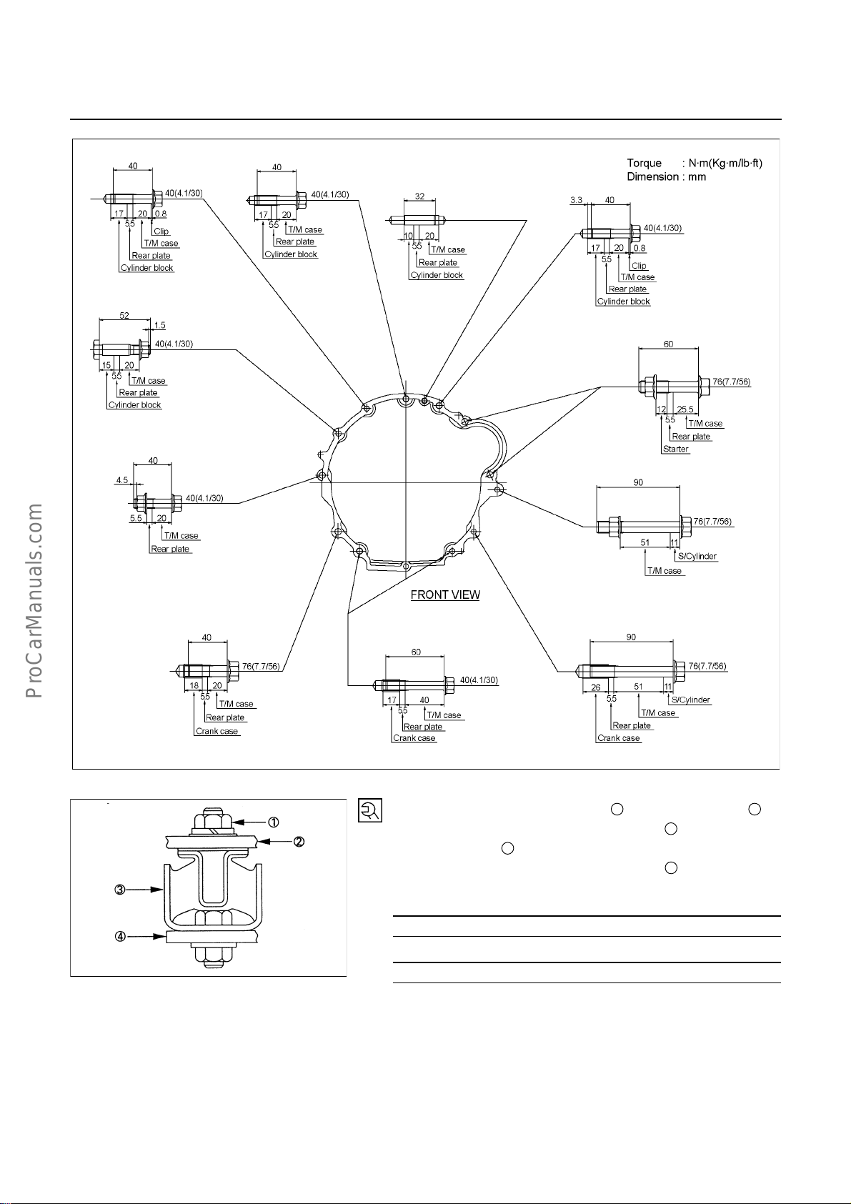
SPECIAL PARTS FIXING NUTS AND BOLTS
N×m (kgf×m/lb×ft)
RTW47BXF000101
Page 8

7B-6 MSG MODEL
REPAIR KIT
1. Case to front cover gasket
2. Control box gasket
3. Plate gasket
4. Filler plug O-ring
5. Drain plug O-ring
RTW47BLF000201
Page 9

MSG MODEL 7B-7
REMOVAL AND INSTALLATION
Read this Section carefully before performing any removal and installation procedure. This Section gives you
important points as well as the order of operation. Be sure that you understand everything in this Section before
you begin.
Important Operations - Removal
Battery Cable
Disconnect the negative (-) cable from the battery terminal.
Engine Hood
Apply setting marks to the engine hood and the engine hood
hinges before removing the engine hood.
Gear Shift Lever
1. Place the gear shift lever in the neutral position.
2. Remove the gear shift lever knob.
3. Remove the front console assembly.
4. Remove the gear shift lever grommet and dust cover.
5. Remove the gear shift lever cover bolts.
6. Remove the gear shift lever.
Note:
Cover the shift lever hole to prevent the entry of foreign
material into the transmission.
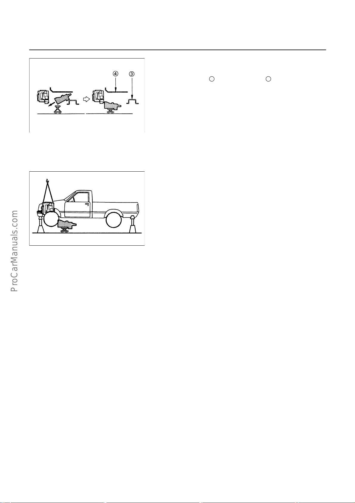
Lifting the Vehicle
1. Jack up the vehicle.
2. Place chassis stands at the front and the rear of the
vehicle.
Transmission Oil Draining
1. Remove the transmission oil drain plug.
2. Replace the drain plug after draining the oil.
Page 10

7B-8 MSG MODEL
Exhaust Pipe
1. Remove the exhaust pipe bracket from the transmission
case.
2. Remove the exhaust pipe.
Rear Propeller Shaft (Single Shaft Type)
1. Remove the propeller shaft flange yoke at the drive pinion
1
.
side
2. Remove the propeller shaft from the transmission main
2
shaft spline
Rear Propeller Shaft (Dual Shaft Type)
1. Apply setting marks to the 2nd propeller shaft flange yoke.
This will prevent mispositioning during the installation
procedure.
2. Remove the 2nd propeller shaft flange yoke bolts at the
drive pinion side
3. Remove the center bearing retainer bolts
4. Remove the 1st propeller shaft with the center bearing and
the 2nd propeller shaft.
Pull the 1st propeller shaft toward the rear of the vehicle
until the spline yoke is free of the transmission main shaft.
Harness Connector
Disconnect the back up light switch connector and the
speedometer sensor connector.
Slave Cylinder
Remove the slave cylinder from the transmission case.
.
1
.
2
.
Page 11

MSG MODEL 7B-9
A
Engine Lifting Hanger
1. Attach the engine lifting hanger to the front portion of the
engine.
2.
ttach the lifting wire to both ends of the engine lifting
hanger.
Starter Motor
Remove the starter motor motor from the engine rear plate.
Transmission
1. Support the transmission with a transmission jack.
2. Remove the engine rear mounting bracket bolts and nuts
from the transmission 2.
3. Remove the bracket from No.3 crossmember.
4. Loosen the nuts for the rear mounting rubber.
3
5. Remove the rear mounting rubber
4
.
6. Remove the gear control box from the transmission.
7. Remove the transmission from the engine.
The removal of the transmission will require the cooperative
efforts of two mechanics.
1) Remove the transmission nuts and bolts
engine rear plate.
2) Place a transmission jack
Do not raise the transmission jack.
2
from the transmission
1
from the
beneath the transmission .
1
Page 12
7B-10 MSG MODEL
3) Manually move the transmission as far as possible toward
the rear of the vehicle (into the space between the No.3
crossmember
4) Lower the clutch housing end of the transmission toward the
transmission jack.
The rear of the transmission is supported by the No.3
crossmember at this time.
5) Firmly grasp the transmission rear cover (1st mechanic).
Raise the transmission jack toward the transmission (2nd
mechanic).
Carefully lower the transmission onto the transmission jack.
The transmission must be centered on the transmission
jack.
8. Carefully pull the transmission jack with the transmission
from beneath the vehicle.
3
and the floor panel 4 .
Page 13

MSG MODEL 7B-11
Important Operations - Installation
Follow the removal procedure in the reverse order to perform
the installation procedure.
Pay careful attention to the important points during the
installation procedure.
Transmission
1. Apply a thin coat of molybdenum disulfide grease to the top
gear shaft spline.
2. Place the transmission on a transmission jack.
3. Carefully move the transmission jack and transmission into
position behind the engine.
4. Slowly operate the transmission jack to raise the
transmission until the rear of the transmission is at the
1
same level as the No.3 crossmember
5. Manually support the transmission rear cover.
Move the transmission into position between the No.3
crossmember and the floor panel
.
2
.
6. Slowly raise the transmission jack until the front of the
transmission is aligned with the rear of the engine.
The slope of the engine and the transmission must be the
same.
7. Install the gear control box the transmission.
8. Align the top gear shaft spline with the clutch drive plate
spline.
9. Install the transmission to the engine.
Tighten the transmission nuts and bolts as shown in the
figure.
Page 14
7B-12 MSG MODEL
RTW37BLF000901
10. Install the rear mounting rubber 3 to the transmission 2.
3
Install the rear mounting rubber
4
crossmember
.
11. Tighten the rear mounting rubber nuts
to the No.3
1
to the specified
forque.
Rear Mounting Rubber Nut Torque N×m (kgf×m/lb×ft)
41 (4.2 / 30)
Mounting Bolt Torgue N×m (kgf×m/lb×ft)
41 (4.2 / 30)
Page 15

MSG MODEL 7B-13
)
Starter Motor
1. Install the starter motor to the engine rear plate.
2. Tighten the starter motor bolts to the specified torque.
Starter Motor Torque N×m (kgf×m/lb×ft)
78 (8.0 / 58)
Slave Cylinder
Install the slave cylinder to the transmission case.
Slave Cylinder Bolt Torque N×m (kgf×m/lb×ft
78 (8.0 / 58)
Harness Connector
Connect the back up light switch connector and speedometer
sensor connector.
Rear Propeller Shaft (Single Shaft Type)
1. Insert the splined yoke 1 with the propeller shaft into the
2
transmission main shaft spline
2. Install the propeller shaft flange yoke
side.
3. Tighten the propeller shaft flange yoke bolt to the specified
torque.
Propeller Shaft Flange Yoke Bolt Torque N×m (kgf×m/lb×ft)
M8 : 35.3 (3.6 / 26)
M10 : 62.7 (6.4 / 46.3)
.
3
to the drive pinion
Rear Propeller Shaft (Dual Shaft Type)
1. Place the center bearing and retainer 1 together with the
2
1st propeller shaft
crossmember
2. Insert the splined yoke
5
spline
3. Tighten the center bearing retainer bolts
torque.
Center Bearing Retainer Bolt Torque N×m (kgf×m/lb×ft)
4. Connect the 2nd propeller shaft
Be sure to align the setting marks applied at disassembly.
5. Tighten the coupling bolts to the specified torque.
Propeller Shaft Flange Yoke Bolt
Torque N×m (kgf×m/lb×ft)
.
and 2nd propeller shaft
3
.
4
into the transmission main shaft
60.8 (6.2 / 44.8)
7
M8 : 35.3 (3.6 / 26)
M10 : 62.7 (6.4 / 46.3)
and drive pinion side 8.
7
6
to the specified
on the No.4
Page 16

7B-14 MSG MODEL
Exhaust Pipe
1. Install the exhaust pipe to the exhaust manifold and the
2nd exhaust pipe.
2. Install the exhaust pipe bracket to the transmission case.
Gear Shift Lever
1. Replenish the transmission case with the specified engine
oil.
Transmission Case Oil lit(US gal.)
1.55 (0.41)
2. Install the gear shift lever to the gear control box.
3. Tighten the gear shift lever cover bolts to the specified
torque.
Shift Lever Cover Bolt Torque N×m(kgf×m/lb×ft)
19.6 (2.0 / 14.5)
4. Install the dust cover and the grommet.
5. Install the front console assembly.
6. Install the gear shift lever knob.
Lowering the Vehicle
1. Place a jack beneath the vehicle.
2. Raise the jack to remove the chassis stands.
3. Lower the vehicle to the ground.
Engine Hood
Align the setting marks(applied at removal)on the engine hood
and the engine hood hinges to install the engine hood.
Battery Cable
Connect the negative (-) cable to the battery terminal.
Page 17

MSG MODEL 7B-15
DISASSEMBLY
MAJOR COMPONENTS
Disassembly Steps
1. Clutch shift block and release bearing
2. Clutch shift fork
3. Speedometer sensor
4. Speedometer driven gear assembly
5. Gear control box assembly
I
6. Front cover with oil seal
I
7. Counter gear snap ring
I
8. Bearing snap ring
9. Rear cover with oil seal
10. Transmission case
11. Intermediate plate with gear assembly
RTW47BLF000301
Page 18

7B-16 MSG MODEL
Important Operations
6. Front Cover with Oil Seal
Remove the front cover with oil seal from the transmission
case.
7. Counter Gear Snap Ring
8. Bearing Snap Ring
Use pair of snap ring pliers to remove the snap ring.
Page 19

INTERNAL PARTS
MSG MODEL 7B-17
MAJOR COMPONENT
Disassembly steps
1. Detent assembly
2. Shift fork assembly & interlock pin
3. Rev. and 5th gear assembly
4. Counter gear shaft assembly
5. Top & main gear shaft assembly
Page 20

7B-18 MSG MODEL
MINOR COMPONENTS
DETENT, SHIFT ARM ASSEMBLY AND INTERLOCK PIN
Disassembly Steps
1. Detent spring plate and gasket
2. Detent spring
I
3. Detent ball
4. Rev. - 5th shaft rod
5. Rev. - 5th shaft arm
6. 1st - 2nd shift rod
I
7. 3rd - 4th shift rod
I
8. 3rd - 4th shift arm
I
9. 1st - 2nd shift arm
10. Interlock pin
11. Intermediate plate and gear assembly
Page 21

MSG MODEL 7B-19
Important Operations
3. Detent Ball
7. 3rd - 4th Shift Rod
8. 3rd - 4th Shift Arm
9. 1st - 2nd Shift Arm
1) Hold a round bar against the shift arm end.
This will prevent damage to other components.
2) Use a spring pin remover to remove the shift arm spring pin
from the shift arm and the shift rod.
Spring Pin Remover : 9-8529-2201-0
Discard the used spring pin.
3) Move the 3rd - 4th shift rod forward.
Take care not to lose the interlock pins.
Page 22

7B-20 MSG MODEL
REVERSE GEAR AND 5TH GEAR
Disassembly Steps
1. Bearing snap ring
2. Speedometer drive gear and lock ball
3. Bearing spacer
4. Mainshaft end ball bearing
5. Thrust ring snap ring
6. Thrust washer thrust ring
7. Thrust washer and lock ball
8. Counter reverse gear nut and washer
I
9. Counter end ball bearing
I
10. Counter 5th gear
11. Counter reverse gear
12. 5th gear
13. 5th block ring
14. Needle bearing
I
15. Mainshaft lock nut and washer
I
16. Rev. - 5th synchronizer assembly
17. Reverse gear
18. Needle bearing
19. Needle bearing collar
20. Thrust washer
21. Counter reverse gear lock nut
22. Thrust washer
23. Reverse idler gear
24. Thrust washer
25. Reverse idler shaft
I
26. Bearing snap ring
I
27. Bearing snap ring
I
28. Intermediate plate
Page 23

MSG MODEL 7B-21
r
Important Operations
9. Counter End Ball Bearing
10. Counter 5th Gear
Use the gear remover to remove the counter 5th gear with the
ball bearing.
Gear Remover : 5-8840-0013-0 (J-22888)
15. Mainshaft Lock Nut and Washer
1) Engage the 3rd - 4th synchronizer with the 3rd gear.
2) Engage the 1st - 2nd synchronizer with the 1st gear.
3) Attach the holding fixture to the mainshaft and the
countergear.
Holding Fixture : 5-8840-2001-0 (J-29768)
4) Use the lock nut wrench to remove the lock nut.
Lock Nut Wrench: 5-8840-0353-0 (J-36629)
16. Rev. - 5th Synchronizer Assembly
1) Remove the synchronizer assembly as a set.
2) Disassemble the synchronizer assembly.
1
Springs
2
Sleeve
3
Clutch Hub
4
Inserts
26. Bearing Snap Ring
1) Insert the snap ring pliers
snap ring hole
2
.
1
into the counter gear bearing
The snap ring hole is in the intermediate plate
3
.
2) Use the snap ring pliers to force open the counter gea
bearing snap ring.
Tap on the front of the intermediate plate.
The ball bearing snap ring will come free.
Page 24

7B-22 MSG MODEL
27. Bearing Snap Ring
28. Intermediate Plate
1) Insert the snap ring pliers into the mainshaft bearing snap
ring hole.
1
The snap ring hole is in the intermediate plate
2
2) Use the snap ring pliers
bearing snap ring
3
.
to force open the mainshaft
.
Hold the snap ring open with the pliers.
3) Push the intermediate plate toward the rear of the
transmission to remove it.
The ball bearing snap ring will come free.
Page 25

MSG MODEL 7B-23
TOP GEAR SHAFT, MAINSHAFT GEAR AND COUNTER GEAR
Disassembly Steps
I
1. Top shaft snap ring
I
2. Top gear shaft
I
3. Ball bearing
4. Needle bearing
5. 4th block ring
6. Mainshaft snap ring
I
7. 3rd - 4th synchronizer assembly
8. 3rd block ring
9. 3rd gear
10. Needle bearing
I
11. Mainshaft ball bearing
12. 1st gear thrust washer
13. 1st gear
14. Needle bearing collar
15. Needle bearing
16. 1st block ring
I
17. 1st - 2nd synchronizer assembly
18. 2nd block ring
19. 2nd gear
20. Needle bearing
21. Mainshaft
I
22. Rear ball bearing
23. Bearing snap ring
I
24. Front ball bearing
25. Counter gear
Page 26

7B-24 MSG MODEL
Important Operations
1. Top Gear Shaft Snap Ring
2. Top Gear Shaft
3. Ball Bearing
1) Use a pair of snap ring pliers to remove the snap ring.
2) Use a bench press and the bearing remover to remove the
ball bearing.
Bearing Remover : 5-8840-0015-0 (J-22912-01)
7. 3rd - 4th Synchronizer Assembly
1) Remove the synchronizer assembly as a set.
2) Disassembly the synchronizer assembly.
1
Springs
2
Sleeve
3
Clutch Hub
4
Inserts
11. Mainshaft B all Bearing
Use a bench press and the bearing remover to remove the ball
bearing.
Bearing Remover : 5-8840-0015-0 (J-22912-01)
17. 1st - 2nd Synchronizer Assembly
1) Remove the synchronizer assembly as a set.
2) Disassembly the synchronizer assembly.
1
Springs
2
Sleeve
3
Clutch Hub
4
Inserts
22. Rear Ball Bearing
24. Front Ball Bearing
Use a bench press and the bearing remover to remove the ball
bearing.
Bearing Removar : 5-8840-0015-0 (J-22912-01)
Page 27

MSG MODEL 7B-25
INSPECTION AND REPAIR
Make the necessary adjustments, repairs, and part replacements if excessive wear or damage is discovered during
inspection.
SHIFT ARM THICKNESS
Use a micrometer to measure the shift arm thickness.
If the measured value is less than the specified limit, the shift
arm must be replaced.
Shift Arm Thickness mm(in)
Standard Limit
1st-2nd 9.6-9.8 (0.378-0.386) 9.0 (0.354)
3rd-4th 6.95-7.2 (0.273-0.283) 6.5 (0.256)
Rev.-5th 6.8-6.9 (0.268-0.272) 6.3 (0.248)
DETENT SPRING FREE LENGTH
Use a venier caliper to measure the detent spring free length.
If the measured value is less than the specified limit, the
detent spring must be replaced.
Detent Spring Free Length mm(in)
Standard Limit
25.6 (1.01) 23.6 (0.93)
DETENT SPRING TENSION
Use a spring tester to measure the valve spring tension.
If the measured value is less than the specified limit, the valve
spring must be replaced.
Valve Spring Tension N(kg/lb)
Compressed
Height mm(in)
22.1 (0.870)
Standard Limit
61.8-65.7
(6.3-6.7/13.9-14.8)
(5.7/12.6)
55.9
BLOCK RING AND DOG TEETH
CLEARANCE
Use a thickness gauge to measure the clearance between the
block ring and the dog teeth.
If the measured value exceeds the specified limit, the block
ring must be replaced.
Block Ring and Dog Teeth Clearance mm(in)
Standard Limit
1st,2nd 2.0 (0.078) 1.3 (0.051)
3rd, 4th, 5th 1.5 (0.059) 0.8 (0.032)
Page 28

7B-26 MSG MODEL
BLOCK RING AND INSERT CLEARANCE
Use a thickness gauge to measure the clearance between the
block ring and the insert.
If the measured value exceeds the specified limit, the block
ring and the insert must be replaced.
Block Ring and Insert Clearance mm(in)
Standard Limit
1st,2nd 3.46-3.74 (0.136-0.147)
3rd, 4th, 5th 3.51-3.79 (0.138-0.149)
4.0 (0.157)
CLUTCH HUB AND INSERT CLEARANCE
Use a thickness gauge to measure the clearance between the
clutch hub and the insert.
If the measured value exceeds the specified limit, the clutch
hub and the insert must be replaced.
Clutch Hub and Insert Clearance mm(in)
Standard Limit
0.01 - 0.19 (0.0004 - 0.0075) 0.3 (0.012)
MAINSHAFT RUN - OUT
1. Install the mainshaft to a grinding machine.
2. Use a dial indicator to measure the mainshaft central
portion run-out.
If the measured mainshaft run-out exceeds the specified
limit, the mainshaft must be replaced.
Mainshaft Run - Out mm(in)
Limit
Less than 0.03 (0.0012)
GEAR INSIDE DIAMETER
Use an inside dial indicator to measure the gear inside
diameter.
If the measured value is less than the specified limit, the gear
must be replaced.
Gear Inside Diameter mm(in)
Standard Limit
1st
Rev.
2nd
3rd
5th
45.00-45.01
(1.7717-1.7720)
41.00-41.01
(1.6142-1.6146)
34.03-34.04
(1.3398-1.3402)
45.10 (1.7756)
41.10 (1.6181)
34.10 (1.3425)
Page 29

MSG MODEL 7B-27
r
r
)
REVERSE IDLER GEAR AND IDLER
GEAR SHAFT CLEARANCE
1. Use a micrometer to measure the idler gear shaft diameter.
2. Use an inside dial indicator to measure the idler gear inside
diameter.
3. Calculate the idler gear and idler gear shaft clearance.
Idler gear inside diameter - idler gear shaft diameter = idle
gear and idler gear shaft clearance.
If the measured value exceeds the specified limit, the idle
gear and/or the idler gear shaft must be replaced.
Idler Gear and Idler Gear Shaft Clearance mm(in)
Standard Limit
0.041 - 0.074 (0.0016 - 0.0029) 0.150 (0.0059)
CLUTCH HUB SPLINE PLAY
1. Set a dial indicator to the clutch hub to be measured.
2. Move the clutch hub as far as possible to both the right and
the left.
Note the dial indicator reading.
It the measured value exceeds the specified limit, the
clutch hub must be replaced.
Clutch Hub Spline Play mm(in
Standard Limit
0.019 (0 - 0.075) 0.20 (0.0079)
Page 30

7B-28 MSG MODEL
r
BALL BEARING PLAY
Use a dial indicator to measure the ball bearing play.
Ball Bearing Play mm(in)
Limit
0.2 (0.0079)
FRONT COVER OIL SEAL
Oil Seal Replacement
Oil Seal Removal
Use a screwdriver to pry the oil seal from the front cover.
Oil Seal Installation
1. Use the oil seal installer to install the oil seal to the front
cover.
Oil Seal Installer : 5-8840-0026-0 (J-26540)
2. Apply engine oil to the oil seal lip.
REAR COVER OIL SEAL
Oil Seal Replacement
Oil Seal Removal
Use a screwdriver to pry the oil seal from the rear cover.
Oil Seal Installation
1. Use the oil seal installer to install the oil seal to the rea
cover.
Oil Seal Installer : 5-8522-0050-0 (J-29769)
2. Apply engine oil to the oil seal lip.
Page 31

INTERNAL PARTS
MSG MODEL 7B-29
REASSEMBLY
MAJOR COMPONENT
Reassembly steps
1. Top & main gear shaft assembly
2. Counter gear shaft assembly
3. Rev. and 5th gear assembly
4. Shift fork assembly & interlock pin
5. Detent assembly
Page 32

7B-30 MSG MODEL
MINOR COMPONENTS
TOP GEAR SHAFT, MAINSHAFT GEAR AND COUNTER GEAR
Reassembly Steps
1. Mainshaft
I
2. Needle bearing
I
3. 2nd gear
4. 2nd block ring
I
5. 1st-2nd synchronizer assembly
6. 1st block ring
I
7. Needle bearing collar
I
8. Needle bearing
I
9. 1st gear
I
10. 1st gear thrust washer
I
11. Mainshaft ball bearing
I
12. Needle bearing
I
13. 3rd gear
14. 3rd block ring
I
15. 3rd-4th synchronizer assembly
I
16. Mainshaft snap ring
17. Needle bearing
18. 4th block ring
I
19. Top gear shaft
I
20. Ball bearing
21. Top gear shaft snap ring
22. Counter gear
23. Front ball bearing
24. Bearing snap ring
I
25. Rear ball bearing
Page 33

MSG MODEL 7B-31
A
Important Operations
2. Needle Bearing
3. 2nd Gear
1) Apply the engine oil to the 2nd needle bearing and the 2nd
gear.
2) Install the needle bearing and the 2nd gear to the
mainshaft.
The dog teeth of the 2nd gear must be facing the rear side
of the transmission.
5. 1st-2nd Synchronizer Assembly
1) Apply the engine oil to the clutch hub spline.
2) Install the synchronizer assembly to the mainshaft.
The outside sleeve heavy chamfering must be facing the
rear of the transmission.
1
Chamfer Angle = 30°
2
Chamfer Angle = 45°
7. Needle Bearing Collar
Use a bench press and the collar installer to install the needle
bearing collar.
Collar Installer : 5-8840-0178-0 (J-33851)
8. Needle Bearing
9. 1st Gear
gear.
pply the engine oil to the 1st needle bearing and the 1st
1)
2) Install the needle bearing and the gear to the mainshaft.
The dog teeth of the 1st gear must be facing the front side
of the transmission.
10. 1st Gear Thrust Washer
Install the thrust washer to the mainshaft.
The thrust washer oil groove must be facing the 1st gear side.
Page 34

7B-32 MSG MODEL
f
A
A
11. Mainshaft B all Bearing
1) Apply the engine oil to the ball bearing inside
circumference.
2) Use a bench press and the bearing installer to install the
bearing.
The bearing snap ring groove must be facing the front o
the transmission.
Bearing Installer : 5-8840-0015-0 (J-22912-01)
12. Needle Bearing
13. 3rd Gear
1)
pply the engine oil to the 3rd needle bearing and the 3rd
gear.
2) Install the needle bearing and the gear to the mainshaft.
The dog teeth of the 3rd gear must, be facing the front side
of the transmission.
15. 3rd-4th Synchronizer Assembly
1)
pply the recommended lubricating oil to the clutch hub
spline.
2) Install the synchronizer assembly to the mainshaft.
1
The sleeve light chamfering
2
boss
must be facing the rear of the transmission.
and the clutch hub heavy
16. Mainshaft Snap Ring
1) Select the snap ring which will provide the minimum
clearance between the mainshaft and the snap ring.
There are four snap ring sizes available.
The snap rings are numbered to indicate their thickness.
Mainshaft and Snap Ring Clearance mm(in)
Standard
0 - 0.05 (0.002)
Snap Ring Availability mm(in)
Thickness Identification Number
1.50 (0.059) 1
1.55 (0.061) 2
1.60 (0.063) 3
1.65 (0.065) 4
2) Use a pair of snap ring pliers to install the snap ring to the
mainshaft.
Page 35

MSG MODEL 7B-33
19. Top G ear Shaft
20. Ball Bearing
Use a bench press and the installer to install the ball bearing
to the top gear shaft.
The snap ring groove must be facing the front of the
transmission.
Bearing Installer : 5-8840-0015-0 (J-22912-01)
25. Rear Ball Bearing
Use a bench press and the bearing installer to install the
bearing to the counter gear.
Bearing Installer : 5-8840-0015-0 (J-22912-01)
Page 36

7B-34 MSG MODEL
REVERSE GEAR AND 5TH GEAR
Reassembly Steps
I
1. Intermediate plate
I
2. Reverse idler shaft
3. Bearing snap ring
4. Bearing snap ring
5. Thrust washer
I
6. Reverse idler gear
7. Thrust washer
I
8. Counter reverse gear lock nut
I
9. Thrust washer
10. Needle bearing collar
11. Needle bearing
12. Reverse gear
I
13. Rev.-5th synchronizer assembly
I
14. Mainshaft lock nut and washer
15. Needle bearing
16. 5th block ring
17. 5th gear
I
18. Thrust washer and lock ball
19. Counter reverse gear
20. Counter 5th gear
21. Counter end ball bearing
I
22. Counter reverse gear nut and washer
I
23. Thrust washer thrust ring
I
24. Thrust ring snap ring
25. Mainshaft end ball bearing
26. Bearing spacer
27. Speedometer drive gear and lock ball
28. Bearing snap ring
Page 37

r
MSG MODEL 7B-35
Important Operations
1. Intermediate Plate
2. Reverse Idler Shaft
1) Install the reverse idler shaft to the intermediate plate.
2) Tighten the reverse idler shaft bolt to the specified torque.
Idler Shaft Bolt Torque N×m(kgf×m/lb×ft)
18.6 (1.9 / 13.7)
3) Set the mainshaft with gear assembly
2
gear assembly
to the holding fixture
Holding Fixture : 5-8840-2001-0 (J-29768)
4) Place the holding fixture (with the mainshaft and the
counter shaft) in a vise.
5) Mesh the 3rd-4th synchronizer to the 3rd gear.
Mesh the 1st-2nd synchronizer to the 1st gear.
6) Install the intermediate plate to the mainshaft and the
counter gear ball bearings.
6. Reverse Idler Gear
8. Counter Reverse Gear Lock Nut
1) Apply the engine oil to the idler shaft and the reverse gea
inside circumference.
2) Install the reverse gear to the idler shaft.
3) Install a new counter reverse gear lock nut.
Never reinstall the old lock nut.
4) Tighten the reverse gear lock nut to the specified torque.
Lock Nut Torque N×m (kgf×m/lb×ft)
107.8 (11 / 79.6)
9. Thrust Washer
1) Apply the engine oil to both sides of the thrust washer.
2) Install the thrust washer to the mainshaft.
The thrust washer oil groove must be facing the reverse
gear side.
1
and the counter
3
.
Page 38

7B-36 MSG MODEL
w
13. Rev.-5th Synchronizer Assembly
1) Apply the engine oil to the clutch hub spline.
2) Install the synchronizer assembly to the mainshaft.
The sleeve heavy chamfer
1
and the insert short side
2
must be facing to the rear side of the transmission.
14. Mainshaft Lock Nut and Washer
1) Install a new lock nut and washer to the mainshaft.
Never reinstall the used lock nut and washer.
2) Use the lock nut wrench to tighten the lock nut to the
specified torque.
Lock Nut Wrench : 5-8840-0353-0 (J-36629)
Lock Nut Torque N×m(kgf×m/lb×ft)
107.8 (11 / 79.6)
22. Counter Reverse Gear Nut and Washer
Tighten the counter gear lock nut to the specified torque.
Reverse Gear Nut Torque N×m(kgf×m/lb×ft)
107.8 (11 / 79.6)
18. Thrust Washer and Lock Ball
23. Thrust Washer Thrust Ring
24. Thrust Ring Snap ring
1) Install the thrust washer with lock ball together with the
thrust ring to the mainshaft.
2) Use a pair of snap ring pliers to install the snap ring.
3) Use a thickness gauge to measure the clearance between
the 5th gear and the thrust washer.
5th Gear and Thrust Washer Clearance mm(in)
Standard
0.1 - 0.3 (0.004 - 0.012)
If required, replace the existing thrust washer with a ne
thrust washer to bring the clearance to specification.
Page 39

MSG MODEL 7B-37
There are six thrust washer sizes available.
Thrust Washer Availability mm(in)
7.8 (0.307) 7.9 (0.311) 8.0 (0.315)
8.1 (0.319) 8.2 (0.323) 8.3 (0.327)
4) Position the thrust ring snap ring gap
2
gap
so that they are separated at a 90° angle.
1
and the thrust ring
Page 40

7B-38 MSG MODEL
DETENT AND SHIFT ARM ASSEMBLY
Reassembly Steps
1. Intermediate plate and gear assembly
I
2. 1st-2nd shift arm
I
3. 3rd-4th shift arm
4. Interlock pin
5. 3rd-4th shift rod
6. 1st-2nd shift rod
I
7. Rev.-5th shift arm
8. Rev.-5th shift rod
9. Detent ball
10. Detent spring
I
11. Detent spring plate and gasket
Page 41

MSG MODEL 7B-39
Important Operations
2. 1st-2nd Shift Arm
3. 3rd-4th Shift Arm
7. Rev.-5th Shift Arm
1) Hold a round bar against the shift rod end lower face to
protect it against damage.
2) Use a spring pin installer to install the spring pin to the shift
arm and the shift rod.
Never reinstall the used spring pins.
11. Detent spring Plate and Gasket.
1) Install the new detent plete and new gasket onto the
transmission case into the correct direction.
2) Tighten the detent spring plate bolts to the specified torque.
Detent Spring Plate Bolt Torque N×m(kgf×m/lb×ft)
18.6 (1.9 / 13.7)
Page 42

7B-40 MSG MODEL
MAJOR COMPONENTS
Reassembly steps
1. Intermediate plate with gear assembly
I
2. Rear cover with oil seal
I
3. Transmission case
I
4. Bearing snap ring
5. Counter gear snap ring
I
6. Front cover with oil seal
7. Speedometer driven gear
8. Gear control box assembly
9. Speedpmeter sensor
10. Clutch shift fork
11. Clutch shift block and release bearing
RTW47BLF000401
Page 43

MSG MODEL 7B-41
A
A
A
RTW47BSH000201
RTW47BSH000301
Important Operations
2. Rear Cover with Oil Seal
1)
lign the pins at the lower side of the rear cover with the
holes in the lower side of the intermediate plate.
2)
pply recommended liquid gasket or its equivalent to the
rear cover fitting surfaces.
3) Install the rear cover to the intermediate plate.
4) Tighten the rear cover bolts to the specified torque.
Rear Cover Bolt Torque N×m(kgf×m/lb×ft)
37.2 (3.8 / 27.5)
Note:
Take care not to twist or puncture the oil seal during the
installation procedure.
3. Transmission Case
4. Bearing Snap Ring
1) Apply the engine oil to the transmission case top gear shaft
ball bearing fitting faces.
pply recommended liquid gasket or its equivalent to the
2)
transmission case fitting surfaces.
3) Install the transmission case to the intermediate plate.
4) Pull the top gear shaft from the transmission case until the
ball bearing snap ring grove protrudes from the
transmission case front cover fitting faces.
5) Use a pair of snap ring pliers to install the snap ring to the
ball bearing.
6. Front Cover with Oil Seal
1) Clean and apply recommended liquid gasket or its
equivalent to the through bolt threads.
2) Install the new gasket and tighten the new cover bolt to the
specified torgue.
Front Cover Bolt Torgue N×m(kgf×m/lb.ft)
24.5 (2.5 / 18.1)
10. Shift Fork
Apply molybdenum disulfide type grease to the areas as
shown in the figure and install shift fork (Diesel engine).
RTW47BSH000101
Page 44
7B-42 MSG MODEL
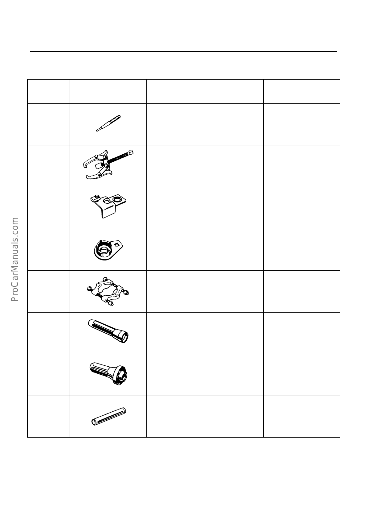
SPECIAL SERVICE TOOL
ITEM NO. ILLUSTRATION PART NO. PART NAME
MTL-42
MTL-1
MTL-9
MTL-35
MTL-3
9-8529-2201-0
5-8840-0013-0
5-8840-2001-0
5-8840-0353-0
5-8840-0015-0
(J-22888)
(J-29768)
(J-36629)
(J-22912-01)
Spring pin remover
Gear remover
Holding fixture
Mainshaft nut wrench
Bearing remover/installer
MTL-13
MTL-14
MTL-21
5-8840-0026-0
5-8522-0050-0
5-8840-0178-0
(J-26540)
(J-29769)
(J-33851)
Front cover oil seal
installer
Rear cover oil seal
installer
Mainshaft collar installer
Page 45

Page 46

No. TFMSG-WE-0431
 Loading...