

Page 1

Model TTI-7-R
Precision Digital Thermometer
Operators Handbook
Isotech North America
158 Brentwood Drive, Unit 4
Colchester, VT 05446
Phone: (802)-863-8050
Fax: (802)-863-8125
www.isotechna.com
sales@isotechna.com
Page 2
ENGLISH
IMPORTANT SAFETY INFORMATION
22/1/97
GENERAL
This instrument has been designed and tested to comply with the Electromagnetic Compatibility Directive 89/336/EEC
and Low Voltage Directive 93/68EEC in accordance with EN 61010 -1 :1995 relating to the safety requirements for
electrical equipment for measurement, control and laboratory use.
Before connecting the instrument to the main supply please ensure the following safety precautions have been read and
understood.
SAFETY SYMBOLS
The following symbols are used to describe important safety aspects of th is instrument, these symbols appear on the
instrument and in the operation instructions.
Attention Symbol:
Indicates a potentially hazardous condition exists and that it is
necessary for the operator to refer to the instruction manual to ensure the safe operation
of thi s instrument.
Hot Surface Warning:
Indicates a hot surface that may be at a temperature capable of
causing burns, refer to the instruction manual for further safety information.
Caution Risk of Electric Shock:
Indicates hazardous voltages may be present,
refer to the instruction manual for further safety information.
Protective Conductor Terminal:
For protection against electrical shock during a fault
condition. This symbol is used to indicate terminals that must be connected to electrical
ground before operating equipment.
SUMMARY OF SAFETY PRECAUTIONS
The following general safety precautions must be observed while operating or servicing thi s instrument. Failure to
comply with these precautions may result in personnel i njur y or death.
INSTRUMENT ELECTRICAL EARTH
This instrument is designed as a Class 1 electrical safety ins ulat ion device. To ensure continued protection from
electric shock the instrument chassis must be connected to an electrical ground. The instrument is supplied with an AC
power cable with an earth connection.
LIVE CIRCUITS DANGER
Do not connect the power supply to or operate thi s instrument with the protective covers removed. Component
replacement and internal adjustments must be made by qua li fied service personnel. Do not replace components with the
power cable connected. Under certain conditions, dangerous voltages may exist with the power cable removed. To avoid
inj ur ie s always disconnect power and discharge circuits before touching them.
DO NOT MODIFY THIS INSTRUMENT OR SUBSTITUTE PARTS
Because of the danger of introducing additional hazards; do not perform any unauthorized modification or i nst a l l
substitute parts to the instrument. Only fuses with the rated current, voltage and specified type should be used,
fai lu re to do so may cause an electric shock or f ir e hazard. Return the instrument to Automatic Systems Laboratories
for service and repair to ensure the safety features are maintained.
DO NOT OPERATE IN EITHER DAMP OR EXPLOSIVE ENVIRONMENTS
This instrument is not designed to operate w h ile wet, in an environment of condensing humidity or in the presence of
flammable gases or vapors. The operation of thi s instrument in such an environment constitutes a safety hazard.
HOT SURFACES DANGER
Equipment marked with a Hot Surface warning symbol should be regarded as operating at temperatures capable of
causing burns. Do not touch, handle or transport hot components or l iqu id s un t il they are at safe temperatures. Care
should be taken not to spill or splash water or volatile fluids on or into hot surfaces or liquids.
CERTIFICATION
Automatic Systems Laboratories certifies that th is product met it s published specifications at the time of shipment
from our factory. A ll calibration measurements performed in the manufacture of t his instrument are traceable to the
National Physical Laboratory (London).
ASSISTANCE
For after sales support and product service assistance please contact Automatic Systems Laboratories Customer
Support Group. Contact information is provided in the operation instruction manual.
Page 3

Contents
Table of Contents
1. INTRODUCTION.................................................................................................................1-1
1.1 Overview ...................................................................................................................1-1
1.2 Definitions and Terminology.......................................................................................1-3
1.3 Principles of measurement........................................................................................1-4
1.3.1 PRT measurement...........................................................................................1-4
1.3.2 Thermocouple measurement............................................................................1-5
1.3.3 Thermocouple reference junction compensation...............................................1-6
2. SETTING UP THE TTI-7-R ............................................................................................... 2-1
2.1 Safety information......................................................................................................2-1
2.2 Unpacking the instrument..........................................................................................2-1
2.3 Voltage selection and fuse rating...............................................................................2-2
2.3.1 Setting the Voltage and Fuse Rating.................................................................2-2
3. ABOUT THE TTI-7-R ........................................................................................................ 3-1
3.1 The Front Panel ........................................................................................................3-1
3.2 On/Off switch and internal battery.............................................................................. 3-1
3.3 The Function Keypad ................................................................................................3-2
3.4 About the TTI-7-R Display ......................................................................................... 3-4
3.5 Thermometer inputs..................................................................................................3-8
3.6 Rear panel .................................................................................................................3-9
3.6.1 AC Power Input Socket..................................................................................3-10
3.6.2 Rating plate ....................................................................................................3-10
3.6.3 Input channel expansion card .........................................................................3-10
3.6.4 RS232/IEEE 488.2 Communication interface card ..........................................3-10
3.6.5 Analogue output .............................................................................................3-10
3.6.6 Name plate.....................................................................................................3-10
4. MEASURING TEMPERATURE...........................................................................................4-1
4.1 Measurement uncertainty and traceability .................................................................4-1
4.2 International temperature scale .................................................................................4-1
4.3 Thermocouple measurement introduction ..................................................................4-3
4.3.1 Connecting thermocouples ................................................................................4-4
4.4 PRT measurement .................................................................................................... 4-4
4.4.1 PRT linearization functions ...............................................................................4-6
5. OPERATING THE TTI-7-R ................................................................................................. 5-1
5.1 About the display screen ...........................................................................................5-1
5.2 About function keys ..................................................................................................5-3
5.3 Power-up sequence .................................................................................................. 5-4
5.3.1 Self-Test ..........................................................................................................5-4
5.3.2 System Configuration....................................................................................... 5-5
5.4 Setting up Measurement Options ..............................................................................5-6
Contents - 1
Page 4

Contents
5.4.1 Selecting thermometer input channel. .............................................................. 5-6
5.4.2 Selecting differential input measurement .......................................................... 5-6
5.4.3 Setting up a PRT measurement....................................................................... 5-7
5.4.4 Setting up a PRT measurement with user defined probe memories.................. 5-9
5.4.5 Setting up a PRT measurement: checking/editing probe memory co-eff. values..
...................................................................................................................... 5-10
5.4.6 Selecting thermocouple type.......................................................................... 5-11
5.4.7 Selecting the reference junction compensation method.................................. 5-12
5.4.8 Selecting ext. ref. junction PRT linearization whose temperature is measured by
a PRT connected to the same channel. ........................................................................... 5-13
5.5 Selecting Screen Display Options........................................................................... 5-14
5.5.1 Selecting measurement units ........................................................................ 5-14
5.5.2 Selecting display resolution modes................................................................ 5-14
5.5.3 Selecting relative temperature measurement .................................................5-14
5.5.4 Using the measurement trigger function [Run/Hold] .......................................5-15
5.5.5 Selecting PRT measurement sense current................................................... 5-15
5.6 Data Logger ............................................................................................................ 5-17
5.6.1 Data logger functions ..................................................................................... 5-17
5.6.2 Setting up the data logger ..............................................................................5-17
5.6.3 Configuring the Scanner ................................................................................ 5-18
5.6.4 Configuring the Timer. .................................................................................... 5-19
5.6.5 Configuring the data log memory ................................................................... 5-21
5.6.6 Starting the data log.......................................................................................5-22
5.6.7 Reviewing log results ..................................................................................... 5-23
5.6.8 Reviewing log statistics .................................................................................. 5-24
5.7 Setting up the basic controls .................................................................................. 5-25
5.7.1 Review system configuration.......................................................................... 5-25
5.7.2 Setting up the TTI-7-R ................................................................................... 5-26
5.7.3 Configuring the communications interface. ..................................................... 5-28
5.7.4 Setting up Trigger Mode................................................................................. 5-30
5.7.5 Displaying the firmware version ...................................................................... 5-31
5.7.6 Adjusting the display contrast........................................................................ 5-31
6. CALIBRATING THE TTI-7-R .............................................................................................6-1
6.1 TTI-7-R Instrument calibration ................................................................................... 6-1
7. COMMUNICATIONS INTERFACE .....................................................................................7-1
7.1 Introduction............................................................................................................... 7-1
7.2 Fitting the Interface................................................................................................... 7-2
7.3 Overview of the RS-232 Serial Interface .................................................................... 7-3
7.3.1 The RS-232 Connector. .................................................................................... 7-4
7.3.2 Pin Connections............................................................................................... 7-4
7.3.3 RS-232 Settings............................................................................................... 7-5
7.3.4 RS-232 Operating Modes ................................................................................. 7-5
7.3.5 RS-232 Interface Commands ........................................................................... 7-6
Contents - 2
Page 5

Contents
7.4 Programming the Interface ........................................................................................7-6
7.4.1 Introduction ......................................................................................................7-6
7.4.2 Command Tree.................................................................................................7-7
7.4.3 Command Directives ........................................................................................7-7
7.4.4 Command Syntax .............................................................................................7-8
7.5 IEEE-488.2 Common Command Group ....................................................................7-10
7.5.1 IEEE-488.2 Common Command Summary.....................................................7-10
7.5.2 IEEE-488.2 Common Commands ..................................................................7-10
7.6 Measurement Command Group ..............................................................................7-14
7.6.1 Measurement command summary...................................................................7-14
7.6.2 CONFigure Commands...................................................................................7-14
7.6.3 MEASure Command .......................................................................................7-18
7.7 SENSe Command Group........................................................................................7-20
7.7.1 Sense command summary.............................................................................7-20
7.7.2 Sense Commands .........................................................................................7-20
7.8 Mathematical Operation Commands........................................................................7-22
7.8.1 CALCulate:AVERage command summary ......................................................7-22
7.8.2 CALCulate:AVERage commands ....................................................................7-22
7.9 Route Command Group ...........................................................................................7-23
7.9.1 Route command summary. .............................................................................7-23
7.9.2 Route commands ...........................................................................................7-23
7.10 Trigger Command Group.....................................................................................7-25
7.10.1 Trigger command summary ............................................................................7-25
7.10.2 Trigger commands..........................................................................................7-25
7.11 System Related Commands ...............................................................................7-29
7.11.1 System command summary...........................................................................7-29
7.11.2 System commands .........................................................................................7-29
7.12 DATAIogger Command Group..............................................................................7-31
7.12.1 Datalogger command summary.......................................................................7-31
7.12.2 Datalogger commands ...................................................................................7-31
7.13 Status Reporting Structure AND Commands ......................................................7-34
7.13.1 The Status Reporting System is summarised in the following diagram.............7-35
7.14 Command Summary...........................................................................................7-39
7.15 Analogue Output.................................................................................................7-42
7.15.1 Specification...................................................................................................7-42
7.75.1 Default Settings..............................................................................................7-42
7.15.1 Analogue Output Connection..........................................................................7-42
8. OPTIONS AND ACCESSORIES ........................................................................................8-1
8.1 Accessories ..............................................................................................................8-1
8.2 High = PRTs ..............................................................................................................8-1
8.3 Low = PRTs .............................................................................................................. 8-2
9. SPECIFICATIONS .............................................................................................................9-1
9.1 Pt100 resistance thermometer measurement............................................................ 9-1
Contents - 3
Page 6

Contents
9.2 Thermocouple measurement............................................................................................ 9-1
9.3 Internal battery operation ................................................................................................. 9-2
9.4 Supply ...................................................................................................................... 9-2
9.5 Environmental........................................................................................................... 9-2
9.6 Data communication interface options ...................................................................... 9-2
9.7 Analogue output option............................................................................................. 9-3
9.8 Display...................................................................................................................... 9-3
9.9 Physical....................................................................................................................9-3
9.10 Pt100 System accuracy ....................................................................................... 9-3
10. CLEANING AND MAINTENANCE................................................................................... 10-1
10.1 Cleaning............................................................................................................. 10-1
10.2 Preventive Maintenance...................................................................................... 10-1
10.3 General Safety Warning .....................................................................................10-1
11. SERVICE AND WARRANTY........................................................................................... 11-1
11.1 Technical Support .............................................................................................. 11-1
11.2 Returned Instruments ......................................................................................... 11-1
Contents - 4
Page 7

1.1 Overview
The TTI-7-R Precision Thermometer is a high accuracy instrument
designed for laboratory and industrial temperature measurement and
calibration applications.
Features include:
• unique dual capability for both thermocouple and resistance
thermometer measurements;
• number of input channel can be expanded from two to ten
channels;
• large graphic LCD display for temperature measurement values
as well as configuration settings and statistical results;
• advanced functions include differential measurement, four
programmable scanning routines, programmable timer, data
logging to none volatile memory, statistical reporting;
• analogue output, IEEE 488 and RS232 communication
interfaces available for automated monitoring and calibration
applications;
• internal battery provides up to 20 hours mains free operation for
remote measurement and data logging applications.
The TTI-7-R will operate with any Pt25 (25 Ohm) and all 2, 3 and 4-wire
Pt100 (100 Ohm) platinum resistance thermometers as well as most
standard international thermocouple types. Temperature measurement
units are selectable by single front panel key operation; °C, °F,K Base
measurement units mV, are also displayed.
Resistance accuracy is better than ±4m for Pt100 400 Ohm range
and ±1.5m for Pt25 100 Ohm range (over full range of –200 to 100°C
at +20°C ±2°C). This is equivalent to temperature measurement
precision of ±15mK for Pt25 thermometers and ±10mK for Pt100
thermometers. Total system measurement uncertainties as low as
±20mK are possible when the TTI-7-R is used with a calibrated
reference thermometer.
1. Introduction
Page 1-1
Page 8

Introduction
Overall system accuracy depends on the PRT quality and calibration. See Section
9 for details of the system measurement accuracy specification.
Standard miniature and 4mm instrument sockets allow convenient connection for
thermocouple inputs. Connection sockets incorporate integral temperature
compensation sensors making high accuracy thermocouple measurement
possible without the use of an external reference junction.
Standard features of the TTI-7-R Precision Thermometer include:
• direct temperature measurement display in °C, °F,K;
• 2 x Pt 25 or Pt100 channel inputs on front panel using 4mm gold plated
spade lug connectors or wire/banana plugs;
• 2, 3 and 4 wire PRT probe measurement;
• Thermocouples B,C,D,E,J,K,N,R,S,T,U,W
• 1 to 20 probe coefficients for ITS90 or CVD entered and stored from
programming PRT calibrations;
• High Accuracy to 0.01 deg.C over –200 to 660 deg.C
• High Resolution 0.001 deg.C for 25/100 Ohm PRT’s and 0.01 deg.C for TC’s;
• Measuring Range –200 to 1100 deg.C for PRT’s and 0 to 2315 deg.C TC’s;
• PRT self-heating and measurement current polarity selection;
• illuminated display;
• compact rugged case;
• 2 to 10 channel expansion with rear panel SPRT, RTD, and TC modules;
• Automatic Cold Junction compensation for TC’s;
• Switched DC (current reversal) option to eliminate thermal e.m.f.s on PRT’s;
• Internal data logging and storage of 4000 measurements;
• Statistical data internally (Min, Max, Peak/Peak, Average, Std. Deviation) ;
• Differential (Difference between any 2 channels connected) ;
• PC interface (RS232) included;
• Portable 20 hour use using internal battery + charger fitted or mains supply;
Page 1-2
Page 9

Introduction
1.2 Definitions and Terminology
i. 0°C = 273.15K
ii. 1 mK (milli-Kelvin) = 0.001 °C (one milli-degree Celsius)
iii. 1 milli-degree C = 0.001 °C = 1m°C = 1mK= 1.8m°F
iv. 1 milli-degree F = 0.001 °F = 1 m°F = 0.56mK = 0.56m°C
v. Alpha, or , is the temperature coefficient, or temperature
sensitivity, of the platinum wire used in PRTs. In general, the
greater the alpha value, the better the PRT thermometer
measurement reproducibility, stability and performance.
vi. Abbreviations for platinum resistance thermometers include: PRT
(Platinum Resistance Thermometer)
Pt100 (PRT with nominally 100 resistance at 0°C) RTD (Resistance
Temperature Device) vii. Thermocouples are referred to as a TC
element or TC sensor.
viii. The TTI-7-R 's thermocouple connection sockets are often referred
to as a temperature compensated reference junction. See Section
1.3 for more details.
ix. System accuracy refers to the overall, combined accuracy of the
TTI-7-R and thermometer.
Key functions and menu options are described as [Function] in the
text or the actual keytop is shown.
General warning symbol. This indicates that a
hazardous condition or general danger may exist.
You must read the relevant sections in the
Operator's Handbook before operating the
instrument.
Page 1-3
Page 10

Introduction
1.3 Principles of measurement
1.3.1 PRT measurement
The TTI-7-R measures the voltage (Vt) developed across the unknown
sensor resistance (Rt) and the voltage (Vs) across a stable internal
reference resistance (Rs) connected in series and passing the same
current. The voltages are in proportion to the resistances so the
thermometer resistance is derived from: Rt = Rs x Vt / V
s
This technique achieves immunity from slow moving time and
temperature drift in the electronics as it is not affected by voltage
measurement gain variations or current source fluctuations.
In the same way that AC resistance measurement eliminates thermal
EMFs, switched DC achieves a similar advantage. Switched DC
works by reversing the current flow on alternate measurement cycles
and taking the average value, thereby cancelling any thermal EMF
offsets from the measurement.
For PRTs, the relationship between resistance and temperature varies
slightly from one PRT to another. Therefore, no matter how accurately
the TTI-7-R measures the PRT resistance, if the relationship between
resistance and temperature for a particular PRT is not known,
accurate temperature measurement is not possible.
The TTI-7-R uses PRT calibration data to overcome this problem and
calculates temperature from temperature conversion functions stored
in internal memory. This method enables the TTI-7-R accurately to
convert resistance to temperature, uniquely for each PRT used. It is
very important therefore that a PRT is used on the correct and
properly configured input channel.
The system accuracy is a combination of the TTI-7-R accuracy in
measuring PRT resistance and the calibration uncertainty placed on
the PRTs by the calibrating laboratory. Using the TTI-7-R with PRT
type 935-14-61, this is ±0.020°C for temperatures from -80°C to
+350°C. See section 9.1 for PRT measurement performance details.
Page 1-4
Page 11

Introduction
1.3.2 Thermocouple measurement
As well as the PRT resistance measurement facility the TTI-7-R also
functions as a precision milli-voltmeter. Designed for high accuracy
measurement over the EMF voltage range of all standard base and
precious metal thermocouples, the TTI-7-R achieves a basic voltage
accuracy of better than 3µV
(at +20 °C ±2 °C) over the full measurement range and significantly
better over smaller ranges. See Section 9.2 for thermocouple
measurement performance details. Thermocouple EMFs are
converted to temperature using the NIST monograph 175
linearization functions. Special types C and D use the linearizations
specified by ASTM E988.
The voltage input connection is specially designed to minimise the
thermal gradient between the terminals. This is particularly important
when the internal reference junction compensation is used, as any
temperature difference at the connection junction will influence the
measurement result. The connection junction is introduced in
Section 1.3.3 below.
Page 1-5
Page 12

Introduction
1.3.3 Thermocouple reference junction compensation
The electrical connection between the thermocouple element and the
TTI-7-R input connector is often referred to as the internal reference
junction. All standard thermocouple reference functions are defined
relative to 0°C. To eliminate the physical need to reproduce this
temperature inside the TTI-7-R , the actual connection temperature
is accurately measured with an internal PRT. This temperature is
converted to an equivalent EMF and added to the actual
thermocouple voltage measurement, thereby correcting for the
connection temperature.
For high precision thermocouple measurement applications, i.e.
calibration, an external reference junction may be used. Using an
external reference junction eliminates the uncertainties associated
with reference junction compensation.
Page 1-6
Page 13

2.1 Safety information
Please read and follow these important safety instructions:
• Read the safety information sheet at the beginning of this
handbook before operating the TTI-7-R ;
• Make the necessary electrical safety and connection checks. In
particular, select the correct line voltage and make sure that the
correct AC power fuse is installed. Incorrect voltage or fuse
selection present both an electrical safety and a fire hazard.
2.2 Unpacking the instrument
When you unpack the TTI-7-R thermometer, check that the following
items are present before starting to use the unit:
• 1x TTI-7-R thermometer
• 1 x AC power cord
• 1x Operator's handbook
• 1x Calibration certificate
Please contact the ISOTECH NA Technical Services Group
immediately if any of these items are missing or damaged.
2. Setting up the TTI-7-R
Page 2-1
Page 14

Setting up the TTI-7-R
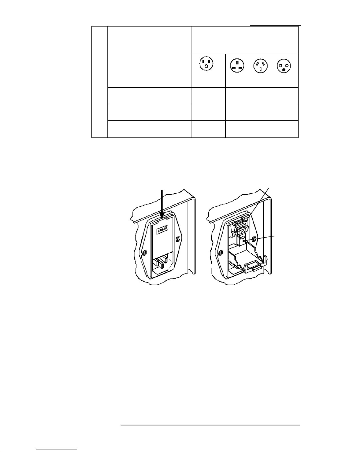
2.3 Voltage selection and fuse rating
The AC Power Input Unit incorporates a voltage selector and fuse
holder, to enable the TTI-7-R operating voltage and fuse rating to be
selected for the local AC electricity supply. The table below describes
the correct voltage selection range and fuse to use.
Voltage Selection
Voltage Range
Fuse Type
100V 90-110V T630mA (250V AC)
120V 108- 132V T630mA (250V AC)
220V 198-244V T315mA (250V AC)
240V 216-264V T315mA (250V AC)
WARNING: DO NOT CONNECT THE POWER
CABLE UNTIL THE VOLTAGE AND FUSE RATING
OF THE INSTRUMENT HAVE BEEN CHECKED
AND CHANGED IF NECESSARY.
2.3.1 Setting the Voltage and Fuse Rating
Lever open the Power Input Unit from the top with a flat bladed
screwdriver. Inside is a plastic cam: remove this and replace it so that
the voltage to be set is displayed through the window as detailed in
Figure 2.1.
Where fused plugs are connected to the AC power cord, the correct
fuse rating is 3 Amps. The AC power cord provided with the TTI-7-R is
colour coded in accordance with national standards to match the plug
type fitted, as follows:
Page 2-2
Page 15
Setting up the TTI-7-R
Earth (protective conductor) Green Green/Yellow
Live Black Brown
Neutral White Blue
Figure 2.1 - Fused Power Input Unit and Voltage Selector
INSERT SCREWDRIVER
TO LEVER DOOR OPEN
VOLTAGE SELECT
PLASTIC CAM
FUSE
HOLDER
Page 2-3
Page 16

Setting up the TTI-7-R
This page has been left blank intentionally
Page 2-4
Page 17
3. About the TTI-7-R
This section introduces you to the features and functions of the TTI-7-
R Precision Thermometer.
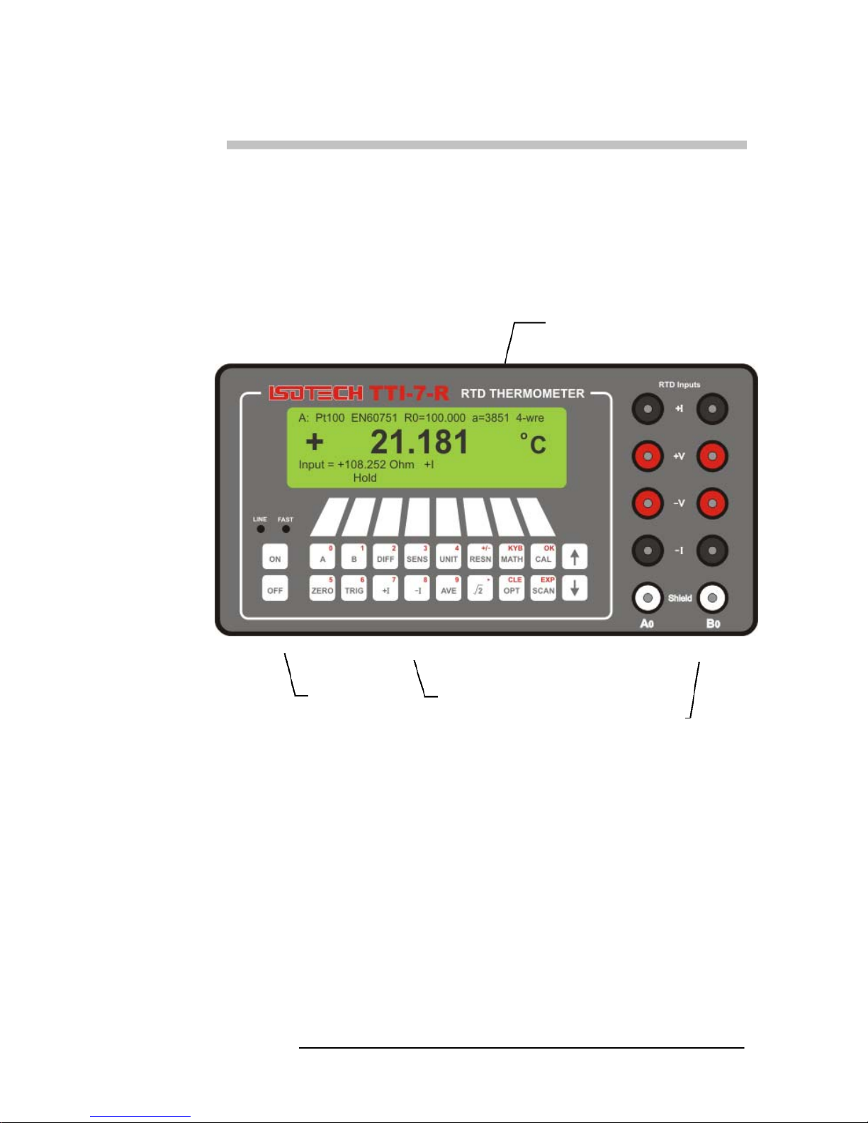
3.1 The Front Panel
Figure 3.1- Front Panel
On/Off
switches
Function keys
Display
Thermometer
inputs
3.2 On/Off switch and internal battery
The ON / OFF keys switch the TTI-7-R on and off. During power
on all TTI-7-R measurement functions are reset to their default state.
It is important to note that THE POWER OFF FUNCTION DOES
NOT DISCONNECT THE TTI-7-R FROM THE ELECTRICITY
SUPPLY. The power supply remains connected to the mains supply.
Page 3-1
Page 18

About the TTI-7-R
Battery charging operation is unaffected by the ON / OFF
key operation.
The TTI-7-R 0 may be operated from the AC electricity supply or the
internal battery. Fully charged batteries provide approximately 8 hours
continuous operation. The internal battery charger operates
whenever the electricity supply is connected. Front panel LEDs
indicate connection to the AC electricity supply and when the battery
is charging.
The batteries are a sealed lead acid type and require no routine
maintenance. Continuous charging causes no harm to the batteries.
Operate the TTI-7-R from the mains when possible to ensure the
batteries are always fully charged.
<LOW BATTERY> indication is displayed when the batteries have
approximately 10% charge or 50 minutes operating time remaining.
To extend the battery operation time, switch the display backlight off.
See Section 5.6.1.
If the batteries are left discharged for a long time, they become
difficult to charge on the first re-charging cycle. During this first re-
charge, it may not be possible to turn on the TTI-7-R . Leave the TTI-
7-R connected to the AC electricity supply for at least 12 hours to
allow the batteries to fully re-charge before using the TTI-7-R again.
3.3 The Function Keypad
All TTI-7-R measurement and programming facilities are accessed
through the function keypad. A brief description of key functions is
given in the table below. For a detailed description of how to use the
keys to configure and operate the TTI-7-R , refer to Section 5.
Page 3-2
Page 19

About the TTI-7-R
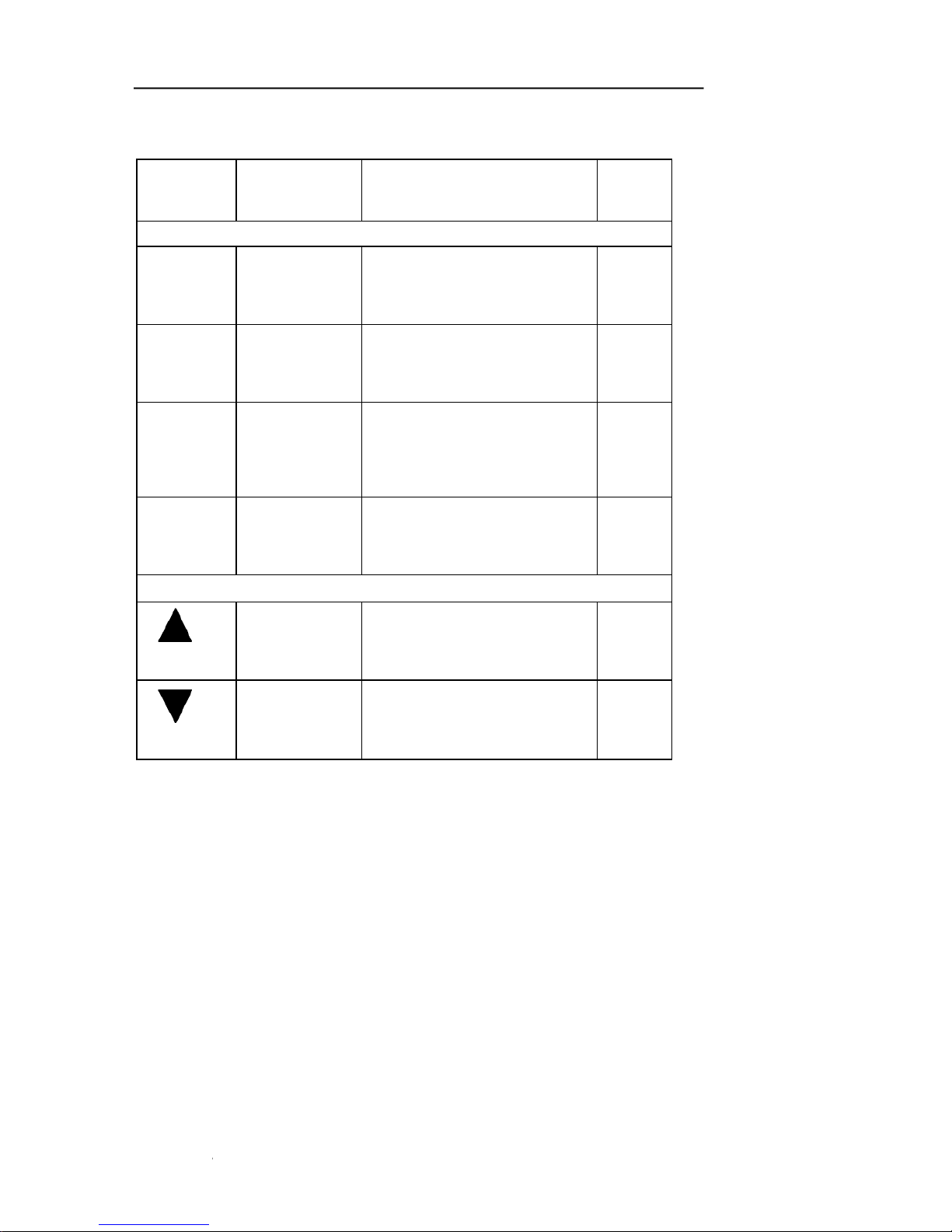
Table 3.1 Summary of basic key functions
Page 3-3
Key symbol Description Function
Direct
function
or Menu
Setting up Input Channels
A
Select input
channel A0 to A4
Selects and displays
measurement channel A0 to A4
Direct
from
keypad
B
Select input
channel BO to B4
Selects and displays
measurement channel BO to B4
Direct
from
keypad
Diff
Select differential
measurement Ch1 Ch2
Relative measurement function
which displays the difference
between the Ch1 and Ch2 inputs
Direct
from
keypad
Setting up Measurement Options
SENS
Temperature
sensor type
Selects sensor type and
measurement configuration for the
selected channel
Menu
UNIT
Measurement
units
Selects measurement display
units: °C, °F, K
Direct
from
keypad
RES
Measurement
display resolution
Selects measurement display
resolution: Thermocouple: 0.1,
0.01 PRT:0.01, 0.001
Direct
from
keypad
ZERO
Measurement
display zero
function
Nulls the display at the current
reading and displays measured
values relative to the nulled value.
Direct
from
keypad
TRIG
Measurement run/
hold/single step
Display hold function, triggers
single or continuous
measurement.
Direct
from
keypad
Logging Data and Statistical Displays
MATH
Math display
functions
Selects the math menu statistical
display and function
Menu
CAL
Calibration menu
functions
Selects the instrument calibration
menu functions
Menu
Options and configuration
OPT
Setup options and
functions
Selects the instrument
configuration options menu and
communication interface
functions
Menu
Page 20
About the TTI-7-R
(Table 3.1 continued:)
SCAN
Scanner, timer
and data logger
functions
Scanner, timer and data logger
menu.
Menu
PRT measurement current
+ l
PRT
measurement
positive current
mode
Positive PRT measurement
current polarity selection
Direct
from
keypad
-I
PRT
measurement
negative current
mode
Negative PRT measurement
current polarity selection
Direct
from
keypad
AVE
PRT
measurement
current reversal
mode
Measures average sensor
resistance with successive
positive and negative current
polarity Default PRT
measurement state
Direct
from
keypad
2
PRT
measurement 2
current selection
2 measurement current division,
reduces measurement current to
allow PRT self heating effect to be
calculated
Direct
from
keypad
Scroll and contrast control
Up command
key; Display
contrast, page
scroll
Controls the display contrast and
page scroll functions
Direct
from
keypad
Down command
key; Display
contrast, page
scroll
Controls the display contrast and
page scroll functions
Direct
from
keypad
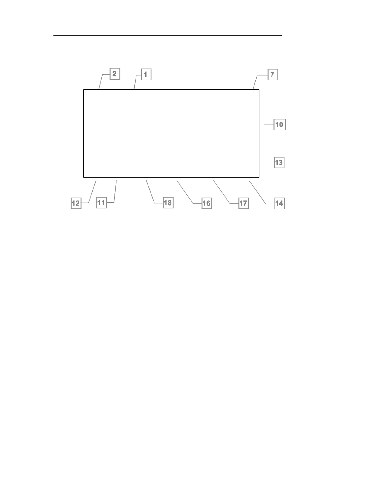
3.4 About the TTI-7-R Display
The liquid crystal graphic display clearly indicates the measured
temperature and measurement status as well as displaying available
menu options and measurement analysis when selected. Whilst in
Temperature Mode (see Section 5.1), there are three possible
display layouts:
Page 3-4
Page 21

About the TTI-7-R
Figure 3.2 - Main display layout (PRT measurement)
A1 Pt100 IEC751 / R0 = 100.000 a=3850 4-wre
+ 18.90 °C
Input = +106.591 Ohm Ave
XXXX/YYYY
Figure 3.3 - Main display layout (Thermocouple measurement)
A1 TC Type
N
RJ Mode= Internal
+ 18.90 °C
Input = -0.170 mV RJ = +24.62 deg C
Mem Adr Rem
Page 3-5
Busy
LOBAT
Run Mem Adr
Zero
Rem
SLX
Busy
LOBA
T
Run
X
XXX/YYYY
Zero SL
X
Page 22
About the TTI-7-R
Figure 3.4 -Main display layout (Relative A1-B1 measurement)
A1-B1
- 0 . 1
°C
Busy
LOBAT
Adr
XXXX/YYYY
The table below describes the location of information as it appears in the
various display layouts:
Page 3-6
Run
Re
Mem
Zero SL
X
Page 23

About the TTI-7-R
Table 3.2 - Measurement mode display features
PRT measurement Thermocouple Relative Ch1 - Ch2
1
Selected channel
temperature
Selected channel
temperature
Temperature
difference between
CM and Ch2
2
Input channel
selected
Input channel selected CM - Ch2
3
Pt100 TC Not used
4
PRT linearization
standard
Thermocouple type
selected, letter
designation
Not used
5
PRT alpha value
Reference junction
mode
Not used
6
3, 4 wire
measurement
configuration
Not used Not used
7
Temperature display
units
Temperature display
units
Temperature display
units
8
Measured input value
in Ohms
Measured input value
in mV
Not used
9
Measurement current
polarity
Reference Junction
temperature if selected
Not used
10
Measurement status Measurement status Measurement status
11
Trigger run/ hold,
single condition
Trigger run/ hold,
single condition
Trigger run/ hold,
single condition
12
Measurement zeroed
indication
Measurement zeroed
indication
Measurement zeroed
indication
13
Low Battery indication Low Battery indication Low Battery indication
14
Re mote/Addressed
remote operation
Remote/Addressed
remote operation
Re mote/Addressed
remote operation
15
R0 value in ohms Not used Not used
16
X samples taken of Y
number of samples
X samples taken of Y
number of samples
X samples taken of Y
number of samples
17
Logging data to none
volatile memory
Logging data to none
volatile memory
Logging data to none
volatile memory
18
Scanning mode ON
SLx scan list
Scanning mode ON
SLx scan list
Scanning mode ON
SLx scan list
Page 3-7
Page 24
About the TTI-7-R
3.5 Thermometer inputs
The TTI-7-R has two main thermometer input channels, the input
sockets are located on the instruments front panel.
The two input channels can be independently configured for
measurement of PRT sensors or thermocouples.
Separate connection is provided for PRTs and thermocouples,
enabling easy direct connection of most thermometer types.
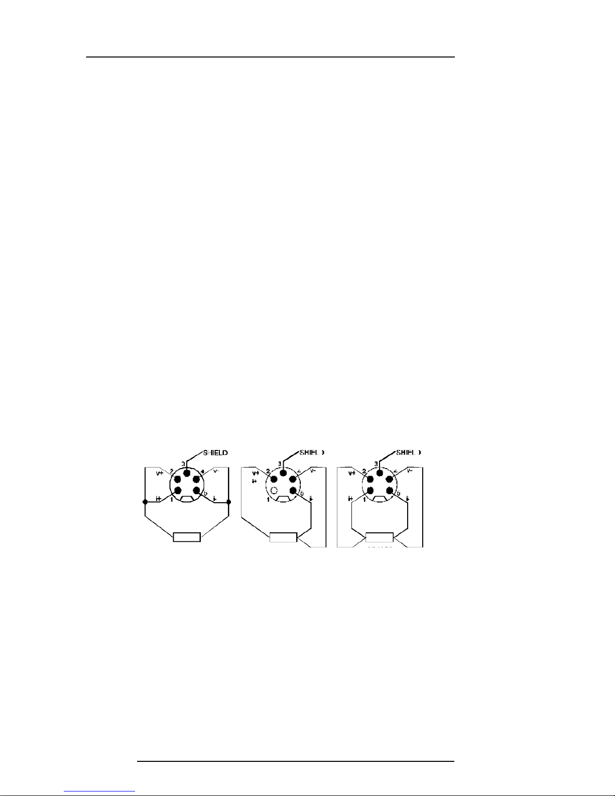
PRTs are connected via the 5 pin DIN sockets. You may connect 2, 3,
or 4 wire PRTs as shown in Figure 3.5. See Section 5.3.3 on PRT
selection. Un-terminated platinum resistance thermometers may be
connected through an optional adapter box which is available as an
accessory, (Part Number FA-ADAP-250). Refer to the Accessory
section at the end of this handbook.
Figure 3.5 - PRT input connection configuration
PRT CONNECTION - 2 WlRE PRT CONNECTION - 3 WIRE PRT CONNECTION - 4 WIRE
(5-pin DIN connector) (5-pin DIN connector) (5-pin DIN connector)
Pt100
R100
R100
View towards front panel connector
Thermocouples may be directly connected to the TTI-7-R either at the
standard miniature sockets or the two 4mm instrument sockets as
shown in Figure 3.6. Special adapter connectors are available for
connecting bare wire thermocouples to the TTI-7-R . These sockets
are within a temperature compensated isothermal block which
eliminates the need for an external ice point reference junction.
However, the TTI-7-R may also be used with an external ice point
reference for high precision measurement and calibration work.
Page 3-8
Page 25

About the TTI-7-R
Figure 3.6 - Thermocouple input connection
THERMOCOUPLE
CONNECTION
LOW THERMAL EMF
COPPER BANANA (4mm)
PLUGS
3.6 Rear panel
Figure 3.7 - Rear Panel layout, showing all options
PRT expansion
module ( op t ional)
Thermocouple
expansion module
(optional)
RS232or I EE E
Communications
Interface (optional)
Analogue output
(optional)
Voltage selector
and fuse cover
Name plate
IE C power
connector
Rating plate
Page 3-9
Page 26

About the TTI-7-R
3.6.1 AC Power Input Socket
Accepts an IEC type power connector.
The AC power input unit incorporates a voltage selection tumbler, to
enable the user to match the TTI-7-R to the local AC voltage
supply, and a power line fuse holder.
3.6.2 Rating plate
Instrument rating plate, contains the AC voltage selection and line
fuse rating, operating supply frequency range, the instrument
maximum power consumption and instrument serial number.
3.6.3 Input channel expansion card
Optional input channel expansion card slots. Blanking plates are
fitted if there is no input channel expansion cards.
3.6.4 RS232/IEEE 488.2 Communication interface card
Optional RS232/IEEE 488.2 communication interface card slot. A
blanking plate is fitted if there is no communication interface card.
3.6.5 Analogue output
Optional analogue output BNC socket. A blanking plug is fitted if
there is no analogue output.
3.6.6 Name plate
Instrument name plate, contains the manufacture name and
address details.
Page 3-10
Page 27

4.1 Measurement uncertainty and traceability
Measurement is usually made on the assumption that there is a true
value. Whenever a measurement is performed it is unlikely that the
measured value will equal the true value. The difference between the
two values is the measurement error which will lie within the specified
limits of uncertainty. Uncertainty is defined as an estimate
characterising the range of values within which the true value lies.
By taking a statistically significant number of measurement samples, a
distribution of results will emerge. Confidence in the distribution
increases as more measurements are made. Using statistical
methods, the distribution may be described in terms of mean, variance
and standard deviation. The uncertainty or precision limit of a particular
measurement is characterised by this distribution.
Traceability is defined as the property of a measurement that may be
related to appropriate reference standards through an unbroken chain
of comparisons. Through traceability it is possible to demonstrate the
accuracy of a measurement in terms of SI units.
4.2 International temperature scale
The purpose of the International Temperature Scale is to define
procedures by which certain specified practical thermometers
including PRTs and thermocouples of the required quality can be
calibrated. The values of temperature obtained from them can be
precise and reproducible, matching at the same time the
corresponding thermodynamic values as closely as current technology
permits.
4. Measuring Temperature
Page 4-1
Page 28

Since 1968 when the International Practical Temperature Scale of
1968 (IPTS68) was adopted, there have been significant advances in
the techniques employed in establishing temperature standards and
in the measurement of thermodynamic temperature. The
International Temperature Scale of 1990 (ITS-90) gives practical
effect to these improvements. Particular features are:
• ITS-90 specifies the use of the PRT up to the freezing point of
silver, 961.78 °C. The platinum 10% rhodium/platinum
thermocouple is no longer specified for use in the scale, though
it and other noble metal thermocouples will continue to be used
as secondary standards.
• New, more precise, fixed points have been introduced and
mathematical procedures for calculating resistance temperature
equivalents have been revised so as to reduce the 'non-
uniqueness' of the scale: that is, to reduce the differences which
occur between different, identically calibrated PRTs. In particular,
the calibration of a PRT can no longer be extrapolated beyond
the freezing point of zinc, 419.527 °C, but requires a
measurement at the freezing point of aluminium, 660.323 °C.
• Alternative definitions are permitted in certain sub-ranges, the
calibration of a PRT can be terminated at almost any fixed point.
This allows primary calibrations to be carried out with suitable
PRTs over reduced ranges, and will be of special importance to
metrology standards departments which need to make precise
measurements at ambient temperatures.
• The part of the ITS-90 scale which may be measured by PRTs
extends from 83.8058 K (-189.3442 °C) to 961.78 °C. The TTI-7-
R
is specified to measure temperature over the range
-200 °C to +962 °C. The actual range of temperatures which may
be measured depends on the type and range of the PRT.
Measuring Temperature
Page 4-2
Page 29

Measuring Temperature
The ITS-90 scale has much improved continuity, precision and
reproducibility compared with IPTS68. The implementation of the
ITS-90 scale according to its definition calls for changes in
equipment and procedure compared with IPTS68, but lower
uncertainties of calibration are achievable in all parts of the range.
However, the instruments and equipment needed to implement the
ITS-90 scale in calibration laboratories will be substantially the
same.
4.3 Thermocouple measurement introduction
Very broadly the thermoelectric effect occurs when an electrical
circuit consisting of dissimilar metal conductors is subjected to a
temperature gradient. An electric potential or voltage is developed
along the conductors. This voltage potential varies proportionally with
temperature and provides a means by which to measure
temperature.
There are two categories of thermocouple:
• Rare metal, Platinum based types
• Base metal, Nickel based
Rare metal, platinum types are mostly used for high temperature
precision thermometry. Maximum temperatures of 1700 °C and
measurement uncertainties of up to 0.3 °C are possible. The
sensitivity of platinum based thermocouples is usually in the region of
10µV/ °C, which means that high accuracy, high resolution
measurements require sensitive instruments such as the TTI-7-R .
Base metal thermocouples easily account for the bulk of temperature
sensors used today, and offer the advantages of being easy to
package into a variety of sensor configurations and relatively low
cost. Base metal thermocouples operate over a wide temperature
range with high temperature types designed for use up to 1600 °C.
Temperatures above 2300°C are possible with new high temperature
tungsten rhenium types. Typical sensitivity figures of
Page 4-3
Page 30

Measuring Temperature
>30µV/ °C characterise most of the base metal thermocouple
family.
Base metal thermocouples are easily affected by contamination
effects which results in decalibration and drift. This is especially
pronounced at high temperatures where drift figures of the order of
10 °C are possible. It is important to be aware of the particular
contamination effects and to select the correct thermocouple for the
measurement environment. The N type thermocouple offers the best
performance in terms of reproducibility and measurement
uncertainty, operating up to 1250 °C. It is the best choice for most
general measurement applications, calling for accuracy with low
time and temperature drift.
4.3.1 Connecting thermocouples
Thermocouples measure temperature difference. As all practical
thermocouples consist of at least 2 junctions, it is important when
performing absolute temperature measurement that one of the
junctions is referenced to a known temperature.
The reference junction and voltage measurement precision
significantly influence the overall temperature measurement
accuracy. Intermediate connection junctions such as connectors and
extension cables between the measurement thermocouple and the
TTI-7-R also influence the measurement result.
4.4 PRT measurement
The TTI-7-R will operate with either 25 Ohm SPRT’s/PRT’s or a
range of 2, 3 and 4-wire 100 Ohm PRTs. The best performance will
be achieved only where good quality PRTs are used from reputable,
proven sources. As with any measured parameter, the performance
of a measurement system depends upon its stability and
repeatability. Low quality PRTs are likely to reduce system
performance.
The relationship between temperature and resistance depends on
several factors, including the alpha value and the PRT calibration.
Page 4-4
Page 31

Consequently more than one equation is required for resistance to
temperature conversion. Calibration data for the PRTs takes the
form of Callendar van Dusen coefficients.
ISOTECH NA Inc. provides a range of proven PRTs especially for
use with the TTI-7-R , as well as offering a service to provide
customised PRTs to meet individual customers' requirements.
High "alpha" PRTs: The best possible system accuracy is
achieved using high "alpha" (Ω) PRTs, or more correctly, PRTs
using high Ω (high purity) platinum wire.
Low "alpha" PRTs: Low Ω PRTs contain a higher level of impurities
in the platinum resistance wire used. This affects the resistance
value at a given temperature (the temperature coefficient). As
impurities already exist in the platinum resistance wire, additional
contamination has a reduced effect and hence low Ω PRTs are more
immune to contamination and are therefore better for industrial
applications. To ensure a robust PRT, the detector within the PRT is
contained within materials, which can themselves be the source of
contamination at elevated temperatures. The PRTs supplied by
ISOTECH NA Inc. have been optimized for the temperature ranges
for which they are specified and, when calibrated, are temperature
cycled to enhance stability in use.
PRTs which are used outside their design and/or calibration
temperature range, especially at higher temperatures, risk
irreversible alteration to their calibration either by induced thermal
stresses or by contamination.
Measuring Temperature
Page 4-5
Page 32

Measuring Temperature
4.4.1 PRT linearization functions
The TTI-7-R provides 3 standard and 20 user definable algorithms
for converting resistance to temperature. The choice will depend on
the type of PRT and its calibration. See also Section 9, which gives
PRT sensor information.
IEC751 (1983):- used for un-calibrated industrial PRTs with
0.003850 "alpha" value, to provide a conversion of resistance to
temperature in accordance with the IEC751 (IPTS 68) standard.
• EN60751 (1992):- used for un-calibrated industrial PRTs with
0.003851 "alpha" value, to provide a conversion of resistance to
temperature in accordance with the
BS EN60751 (ITS 90) standard.
• US/JIS:- used for un-calibrated industrial PRTs with 0.003916
"alpha" value, to provide a conversion of resistance to
temperature in accordance with the JEMIMA standard.
Un-calibrated PRTs conforming to IEC751/DIN43760/BS1904 have
traditionally used the IEC751 pre-programmed standard, which
provides a conversion in accordance with published DIN43760 or
BS1904 tables. These tables were created using temperatures
defined by the superseded International Practical Temperature Scale
of 1968 (IPTS68) and have inaccuracies compared with the
International Temperature Scale of 1990 (ITS-90). ISOTECH NA Inc.
has included the values for standard coefficients from IEC751 and
the more recent
EN60751 standards. The use of EN60751 is now recommended for
use with uncalibrated industrial PRTs.
Page 4-6
Page 33

Measuring Temperature
IEC751
Selecting IEC751 from the standard menu selects the standard
coefficients from IEC751 (DIN43760/ BS1904 -based on IPTS68).
The coefficients for IEC751 are as follows:
Ro A B C
IEC751 100 Ohms 3.90802 x 10
-3
-5.802 x 10⁻⁷ - 4.2735 x 10
-12
EN751
Selecting EN751 from the standard menu selects the standard
coefficients from BS EN60751 based on ITS90. The advantage of this
is that it removes the temperature conversion errors associated with
the old IEC751 standard which is based on the earlier and
superseded IPTS68. The coefficients for EN60751 are as follows:
Ro A B C
EN60751 100 Ohms 3.9083 x 10
-3
-5.775 x 10⁻⁷ -4.183 x 10
-12
US/JIS
Selecting US/JIS from the standard menu selects the standard
coefficients from JEMIMA for high alpha PRT reference
thermometers. The coefficients for US/JIS are as follows:
Ro A B C
JIS/US 100 Ohms 3.97478 x 10
-3
-5.8775 x 10⁻⁷ -3.4813 x 10
-12
Usr
Selecting Usr from the standard menu allows the coefficients
provided with calibrated PRTs to be used in converting resistance to
temperature.
Either 25 or 100 Ohm SPRT’s/RTD’s may be used and coefficients for
ITS90 or Callendar Van Dusen entered. The instrument recognises from
data entered under Ro if a 25 or 100 Ohm probe is being used and
automatically adjusts the measuring range and measuring current.
Page 4-7
Page 34

Measuring Temperature
This page has been left blank intentionally
Page 4-8
Page 35

5. Operating the TTI-7-R
5.1 About the display screen
The TTI-7-R display screen is your direct link to the instrument,
presenting you with information or menus that prompt you on what to
do next.
It has two modes:
• the Temperature Measurement Mode which displays status
information and a sequence of temperature readings;
• the Configuration Mode which lets you set up and configure
the equipment.
Figure 5.1 shows an example of the Temperature Measurement
Mode display. The top line of the screen gives status information: in
this example, an N type thermocouple is connected to input socket
A1 and the internal reference junction method has been selected.
The temperature reading is displayed in degrees Celsius.
Figure 5.1 - Example of Temperature Measurement Mode
A1 TC Type N RJ Mode= Internal
+
18.3
°C
Input = -0.170 mV RJ = +24.62 deg C Busy
Run
The keypad below the display screen controls the TTI-7-R . Some keys
perform a function directly. For example, pressing changes the
temperature units. Other keys switch the display to configuration
mode which allows you to select options through a series of menus.
The option menus all follow the same format. The configuration mode
is indicated on the screen by a dashed line displayed directly
Page 5-1
Page 36

Operating the TTI-7-R
below the main reading. An instruction prompt under the dashed line
indicates the current menu. The available menu options are displayed
on the bottom row of the display as shown in Figure 5.2. Press the
corresponding function key to select an option.
Figure 5.2 - Example of Configuration Mode screen
A1 TC Type
N
RJ Mode= Internal
Sensor Type?
T/C PRT Quit
Indicates
current menu
Indicates menu
options
A white guideline printed on the front panel helps you to link the
menu option printed on the screen with the correct key on the
keypad.
White guideline
indicating which key
to press
Page 5-2
Page 37

Operating the TTI-7-R
5.2 About function keys
You only use the top row of function keys to select menu options. The
lower row of function keys are enabled only when entering numerical
data; these instances are covered later in this section. Both rows of
function keys are shown in Figure 5.3.
Figure 5.3 - Function keys
The [Quit] and [OK] menu options consistently use the QUIT/MATH
and OK/MEM keys. Use the [Quit] key to leave a menu or return to the
Temperature Measurement Mode screen. Use the [OK] key to confirm
a particular choice and continue to the next set of menu options.
Not all function keys are used to access the Configuration Mode. Some
just invoke the function which is printed on the key. For
example, pressing
4/UNIT
cycles you through a sequence of
Celsius, Fahrenheit and Kelvin temperature units. If you miss the
option you want, just continue until it is displayed again.
The rest of this section describes how to set up the equipment, log
data and review the results. It also describes how to modify some of
the settings, such as date and time. Some of these are reset to
default values every time the machine is switched on.
Page 5-3
Page 38

Operating the TTI-7-R
5.3 Power-up sequence
The instruments power on/off is controlled from the
ON / OFF keys located on the TTI-7-R front panel.
On power-up, the TTI-7-R performs a memory self-test routine
followed by a system configuration check.
5.3.1 Self-Test
On power-up the TTI-7-R performs a memory self-test routine
Figure 5.4 - Memory Self-Test Display
Performing Self-Test.......
On successfully completing the memory self-test the TTI-7-R will
report PASSED and proceed with a system configuration check.
If the memory self-test fails the TTI-7-R reports the message FAILED
Press OK to restore defaults.
Figure 5.5 - Memory Self-Test Fail Display
Performing Self-Test......
Failed
Press OK to restore defaults
Press the [OK] key to restore the instrument variables to the factory
default values.
Page 5-4
Page 39

5.3.2 System Configuration
On power-up the TTI-7-R performs a system configuration
check searching for input channel expansion cards or
communication card. The screen displays:
Checking system configuration
The following information is read from each card on detection and
displayed by the system configuration display for 2 seconds.
Communication card
RS-232, Baud rate, Character bits, Parity, Start bit, Stop bit.
IEEE488.2, Address.
Input channel expansion card
Card ID, Serial Number, Card type, Channel numbers.
Figure 5.6 - Example System Configuration Display
System configuration
RS-232 9600,8,0,1,2
Card A1 Sn12345 4Ch TC Ch A1 to A4
Card B1 Sn30123 4Ch PRT Ch B1 to B4
The system configuration can also be reviewed from the options
menu.
After the power-up sequence, the instrument begins its normal
operation.
Operating the TTI
-7-
R
Page 5-5
Page 40

Operating the TTI-7-R
5.4 Setting up Measurement Options
This section describes how to set up the TTI-7-R for your
specific measurement requirements.
You need to select an input channel before configuring a probe.
5.4.1 Selecting thermometer input channel
To select an input channel with no input channel expansion cards
fitted, press ′/A to select input channel AD or 1/B to select input
channel BO.
To select an input channel with an input channel expansion card
fitted, press ′/A to select channels [A0 to A4], press 1/B to select
channel [B0 to B4]. The screen displays:
Enter channel number: (A or B)
Quit
Enter the channel number from the TTI-7-R function keypad at the
A or B prompt. Select [Quit] to return to the main display.
The selected channel number is displayed in the top left hand corner
of the display screen.
If a channel is selected that is not available the TTI-7-R will
display an error message channel not available and prompt for
a new channel number.
5.4.2 Selecting differential input measurement
Press 2/DIFF 1 to select differential measurement with no input
channel expansion cards fitted.
To select differential measurement with an input channel expansion
card fitted press 2/DIFF. The screen displays:
Enter channel number: (Ch1-Ch2):
Quit
Enter the channel numbers from the TTI-7-R function keypad, each
channel number consists of a letter A or B followed by a single
digit number, A and B are entered from the and function
Page 5-6
Page 41

Operating the TTI-7-R
keys. A differential measurement can be taken from any two
available channels. Select [Quit] to return to the main display.
If a channel is selected that is not available the TTI-7-R will
display an error message channel not available and prompt for
new channel numbers.
The selected channels are displayed in the top left-hand corner of the
display screen.
The TTI-7-R will displays the difference between the input channels
[Ch1-Ch2].
5.4.3 Setting up a PRT measurement
Three standard PRT linearization functions are available. In addition,
20 user-definable memories are available for coefficients provided
with calibrated probes. These memories allow calibration coefficients
to be stored in the Callendar van Dusen form for high precision
temperature measurement.
2. For input channels [A0] and [B0], the Sensor type? menu will be
displayed. Select [PRT] option, the standard? menu will be
displayed.
Sensor type?T/C PRT
Quit
For PRT input channel expansion cards the Standard? menu will be
displayed:
Standard?
IEC US/ EN-
Rev 751 Jis 751 Usr Quit OK
3. Next select a linearization standard from the list displayed on the
screen. Note that you cannot start measuring temperature until you
have made this selection.
Page 5-7
1.To configure a selected channel press 3/SENS .
Page 42

The TTI-7-R is pre-programmed with three standard linearization
standards (see Section 4.4.1) as follows:
i. [IEC751] IEC751 (1983)
ii. [EN751] BS EN60751 (1992)
iII. [US/JIS]
JEMIMA
To choose one of these linearization standards, press the
appropriate function key and then [OK] if you want to go on to
configure 3 wire or 4 wire measurement or configure another
channel. Otherwise press [Quit]. The previous 3 wire or 4 wire
settings will remain unchanged.
4. If you press [OK], the screen displays:
Connection?3W 4W
Quit OK
5. Select the connection option you want, select 4 wire measurement
when using 2 wire PRTs.
6. Se lect [Quit] to return to Temperature Measurement Mode.
7. To configure all the channels of an expansion card to the same set
up, select one of the channels on the card and follow steps 1 to 5
above. At the Connection? menu select [OK], the screen displays:
Select channel?
Ch- Ch+ All Quit OK
8. Select [All] to configure all the channels of the expansion card to the
same set-up.
9. [Ch-] and [Ch+] can be used to select a channel without returning to
the Temperature Measurement Mode.
10. On completion of configuring all the input channels select [Quit] to
return to Temperature Measurement Mode.
5.4.4 Setting up a PRT measurement with user defined probe
memories
Operating the TT
I
-7-
R
Page 5-8
Page 43

Operating the TTI-7-R -R
Standard?
IEC US/ EN-
Rev 751 JIS 751 Usr Quit OK
2. Select the [Usr] option. The screen displays:
Enter Probe #(1-20):
Quit OK
3. Enter a number between 1 and 20 using the numbers on the keypad
and then [OK]. The number you have entered is shown on the top
line on the display. If you make an error, press
USER/OPTN
and re-
enter number. The TTI-7-R will only accept values in the range 1-20
and will signal an error if your entry is outside this range.
Page 5-9
1. Press 3/SENS and then the [PRT] function key. The screen displays:
Page 44

Operating the TTI-7-R
5.4.5 Setting up a PRT measurement: checking/editing probe
memory co-eff. values
This allows you to assign coefficient values to probe memories or
check the values already assigned.
1. Press 3/SENS and if PRT and TC inputs used, the screen
requests [PRT] or [TC]. When only a PRT channel is
available (NO channel expansion modules fitted) the screen
shows:
Standard?
IEC US/ EN-
Rev 751 JIS 751 Usr Quit OK
2. Select the [Rev] option. If you have already selected one of
the three standard linearizations, the four pre-programmed
standard coefficients are displayed at the top of the screen.
These cannot be altered.
3. If you want to enter a new set of coefficients, press
User in ‘Standard’ screen above. The screen requests
a probe coefficient set 1 to 20. Enter an empty
memory box number, e.g. 11. The screen displays:
User 11 empty
Enter Quit
4. Select enter. The screen shows:
IPRT SPRTCVD ITS90
5. Select required probe coefficient type, e.g. SPRT, ITS90
and the screen shows:
Ro Ap Bp Cp >> Quit Ok
.
6. Select and enter each coefficient in turn. (If no coefficient
exists, do not enter any value). To enter the coefficient,
e.g. –3.98e-2. first put in a – sign, then the number 3.98
from the front panel keys. For the exponential form, press
the exponential key on the front panel (on the lower right
Page 5-10
Page 45

side) and then the number 2.
7. Go to the next page >> to enter the other coefficients. Dp,
An, Bn, and Wt as in 6, above. Note: The coefficients
entered can be viewed at the top of the screen.
8. Select Ok:
Save new coefficients Yes No
Select Yes.
9. If you are entering CVD coefficients, select CVD in item 4
above. Then proceed as in items 5, 6 and 7 to enter the Ro,
A, B and C terms.
Note: The 20 probe memories are already calibrated with the BS
EN60751 standard when the unit is shipped. This lets you obtain
sensible results from the onset; you can go back and edit the probe
coefficients at a later date, not necessarily at the time you select
them.
5.4.6 Selecting thermocouple type
1. Press and then the [TC] menu key. The screen displays:
Thermocouple type?
B C D E J » Quit OK
2. Select one of the ten thermocouple standards supported; B, C, D,
E, J are displayed on the first screen: K, N, R, S, T on the second.
Switch between the screens with the [»] key. Type the appropriate
key and then [Quit]. Measurement will start as soon as you have
selected the standard you want. The thermocouple type is displayed
in the top left-hand corner of the screen.
Page 5-11
Page 46

Operating the TTI-7-R
5.4.7 Selecting the reference junction compensation method
1.
You can select the reference junction compensation method after
selecting the thermocouple type by pressing [OK] instead of [Quit].
The screen displays:
RJ mode?
Off Int Ext Quit OK
The menu options list the three reference junction methods
supported:
Menu option
Description When used
[Int]
Internal reference junction
compensation using the
TTI-7-R 's internal
temperature compensated
copper isothermal junction.
This is the default mode.
For direct temperature
connection with no
external reference
junction. High accuracy
measurement, requiring
no additional connection
reference junctions.
[Ext]
External reference
junction compensation
using PRT measurement
of reference junction. No
measurement channels
are lost as the reference
channel PRT uses the
corresponding input
channel.
For temperature
controlled or ovenised
reference junctions.
[Off]
No reference junction
compensation applied to
the measurement. All
measurements are made
with respect to 0 °C.
Used with an external ice
point reference junction.
Suitable for highest
precision measurement.
Select the reference junction method with the appropriate function key.
If you have selected [Off] or [Int], you can now press [Quit] to start
measurement.
Page 5-12
Page 47

5.4.8 Selecting ext. ref. junction PRT linearization whose
temperature is measured by a PRT connected to the same channel.
1. The [Ext] menu option allows you to set up an external reference
junction whose temperature is measured by a PRT connected to the
same channel. When you select [Ext] you are prompted to choose
the PRT linearization for this PRT, the screen displays:
Standard?
IEC US/ EN751 JIS 751 Usr Quit OK
2. This lets you choose one of three standard linearizations which can
be used with uncalibrated probes. A fourth option, [Usr], gives you
access to the 20 probe memories for Callendar van Dusen
coefficients provided with calibrated probes.
3. If you want to select one of the standard linearization options,
[IEC751], [US/JIS] or [EN751], press the appropriate function key
and then [Quit]. Reference junction information is displayed at the
top right hand corner of the screen, e.g.
RJ Mode= Ext US/JIS
4. If you want to access one of the probe calibrations already in
memory, press [Usr]. The screen displays:
Enter Probe #(1-20):
Quit OK
Use the keypad to enter the probe number and then press [Quit].
Section 5.3.5 describes how to enter user coefficients.
Operating the TTI-7-R
Page 5-13
Page 48

Operating the TTI-7-R
5.5 Selecting Screen Display Options
This section describes how to modify information displayed by the TTI-
7-R . It covers:
5.5.1 Selecting measurement units
Press 4/UNIT to sequence between the three measurement units
available. These are Celsius (°C), Fahrenheit (°F) and Kelvin (K). The
measurement unit selected is applied to all temperature displays,
including logged data.
5.5.2 Selecting display resolution modes
Press +-/RES to toggle between the two display resolution modes
available. The table below gives the display resolutions for
thermocouple and PRT inputs. The TTI-7-R defaults to low resolution
mode when first switched on.
High
Low
Thermocouple 0.01
0.1
PRT 0.001 0.01
5.5.3 Selecting relative temperature measurement
In Zero mode, the TTI-7-R displays temperature relative to a fixed
reference point. Press 5/ZERO to store the current display value; this
will be subtracted from all subsequent readings. To cancel Zero
mode, either press 5/ZERO again, change the input channel, change
the sensor type or turn off the power.
When Zero mode is enabled, a Zero message is displayed in the
bottom left hand corner of the screen.
Page 5-14
Page 49

Operating the TTI-7-R
5.5.4 Using the measurement trigger function [Run/Hold]
The TTI-7-R default trigger mode is Run/Hold. It can also be
configured
to operate in single shot mode. Press the key to alternate
between continuous measurement (Run), and measurement hold
(Hold). Measurement hold mode stops all measurement operations,
freezing the current display value. It also halts all scanning and data
logging operations. When measurement hold is enabled, a Hold
message is displayed on the bottom line.
Press 3/TRIG again to resume measurement, scanning or data
logging operations. A Run message is displayed on the bottom line
and the message Busy flashes on every time a new temperature
measurement is taken.
Setting the trigger mode to single shot mode is described in Section
5.6.3. In single shot mode, the TTI-7-R remains in the hold state until
you press the 3/TRIG key; it then captures a single
measurement reading.
If you have scanning enabled this allows you to single step through the
scanning routine.
If the data logger is enabled all the spot readings will be stored in the
data log memory.
5.5.5 Selecting PRT measurement sense current
PRT measurement uncertainty can be affected by external EMFs and
PRT self heating. The TTI-7-R allows you to select the measurement
sense current magnitude and polarity so that you can evaluate the
magnitude of such external factors.
a) Selecting positive measuring current polarity (+I)
Press /+1 for positive measuring current polarity. The
measurement time is approximately 1.8 seconds per reading for
channels A and B, and 3.6 seconds for Ch1-Ch2 relative
measurement.
Page 5-15
Page 50

Operating the TTI-7-R
b) Selecting negative measuring current polarity (-I)
Press for reversed or negative measuring current polarity. The
measurement time is approximately 1.8 seconds per reading for
channels A and B, and 3.6 seconds for Ch1-Ch2 relative
measurement.
c) Selecting average current
Press 9/AVE to select automatically alternated dc measuring current
polarity switching at a rate of approximately O.SHz. Thermal EMF
measurement errors are eliminated by taking the average value of the
forward and reverse polarity readings. The measurement time is
approximately 3.6 seconds per reading for channels A and B, and 7.2
seconds for Ch1-Ch2 relative measurement. The Average current
mode is the power up default condition.
d) Selecting 2 current multiplier
This option reduces current through the probes by 2 (half-power), to
determine any probe self heating. The best method of using this option
is first to let the sensor reach a steady temperature and note the value.
It may take some time to stabilise.
Press and immediately select the reduced current through
the probe will reduce the heating effect on the probe, and the value
displayed will represent the temperature change due to the reduced
current.
When the reading has stabilised, note the temperature change. Add
twice the temperature change to the original temperature (observing
the sign; the final temperature should be lower than the original
value). The result is the actual temperature with the effect of probe
self heating eliminated.
Page 5-16
Page 51

Operating the TTI-7-R
5.6 Data Logger
The TTI-7-R is fitted with a very powerful easy to use data logger.
The data logger consists of three functions, each function can be
used independently, or all three functions can be combined to
provide the powerful data logger.
5.6.1 Data logger functions
Scan: The scanner function lets you switch between a number of
input channels. Up to four independent scanning lists can be
configured and stored in non-volatile memory. A scanning list
consists of a list of channels, the timer cycle delay, sample rate and
cycle count. Each scanning list can be quickly set-up, reviewed and
edited.
Timer: The built in timer can be programmed to control the cycle
delay, sample rate and the cycle count.
Mem: Up to 4000 readings can be stored to none-volatile memory with
a time and date stamp for review later.
5.6.2 Setting up the data logger
Press the SCAN key to bring up the data logger menu. The
screen displays:
Scanner is: Off Memory is: Off
Scan Timer Mem Quit OK
The first line of the menu shows the current configured state of the
data logger modules.
Scanner is: Indicates the scanner is OFF or the selected scan list
when the scanner is ON.
Memory is: Indicates the data logging to memory ON/OFF state.
Page 5-17
Page 52

Operating the TTI-7-R
5.6.3 Configuring the Scanner
To access the scanning list menu, select [Scan] from the data
logger menu. The screen displays:
Scanning list is: Off
SL1 SL2 SL3 SL4 Edt Off Quit OK
Switching scanner on/off: Scanner OFF is the default state when
the instrument is powered up. To switch the scanner ON select one
of the scanning lists [SL1] to [SL4]. To switch the scanner OFF
select [Off] from the menu. The first line of the menu shows the
current state of the scanner.
Edit a scanning list: To edit a scanning list, first select the
scanning list to be edited, then select [Edt] from the scanning list
menu. The screen displays:
Scanning list edit: SL1
AD BO A1 A2 A3 A4 B1 B2
< > Add Del Quit OK
The scanning list edit menu can display up to eight channels on
each page at a time, only available channels in the system will be
shown.
To add or remove a channel from a scanning list, position the
flashing cursor over the appropriate channel using the [<] or [>]
options.
Use the [Add] or [Del] options to add or delete a channel to the
scanning list.
Active channels in the scanning list are shown in reverse text (white
on black), none active channels are shown in normal text (black on
white).
Figure 5.7- Example of a scanning list
Scanning list edit: SL1
A0
BO A
1 A2 A3 A4
B
1 B2
< > Add Del Quit OK
Channels A0, A1, A2, A3 and B1 are active channels that will be
scanned, the remaining channels will not be scanned.
Page 5-18
Page 53

5.6.4 Configuring the Timer
The instrument timer function can be programmed to control the
measurement sample rate, cycle delay and cycle loop count. Figure
5.8 details the timer flow diagram for single channel data logging,
figure 5.9 details the flow diagram for multiple channel data logging.
To access the timer edit menu, select [Timer] from the data logger
menu. For single channel data logging (scanner off), the screen
displays:
Cyc=Cont Delay=00:00:00
< > Clear Edit Quit OK
For multiple channel data logging (scanner on), the screen displays:
Cyc=Cont Delay=00:00:00 Rate=00:00:00
< > Clear Edit Quit OK
To set-up the timer, use the [<] and [>] options to position the
flashing cursor over the appropriate parameter to edit.
To set a parameter to its default value select [Clear].
To edit the parameter value select [Edit], the screen display:
Cyc=Cont Delay=00:00:00 Rate=00:00:00
OK
Enter the required parameter value directly from the TTI-7-R
numerical key-pad and select [OK] to return to the timer edit menu.
Errors can
be cleared using the front panel key. Repeat the process for
each of the timer parameters.
Timer Parameters
Cyc= Sets the number of scanning cycles required (1 to 9999 or
continues), default value is continues.
Delay= Sets the required delay hh:mm:ss between scanning cycles
(00:00:00 to 99:59:59 seconds), default is 00:00:00.
Rate= Sets the required delay hh:mm:ss between samples
(00:00:00 to 99:59:59 seconds), default is 00:00:00.
Operating the TTI-7-R
Page 5-19
Page 54

Figure 5.8 - Single channel timer flow diagram
Figure 5.9 - Multiple channel timer flow diagram
Page 5-20
Operating the TTI-7-R
Page 55

5.6.5 Configuring the data log memory
The TTI-7-R can record up to 4000 readings in none-volatile data log
memory. You can analyse this data either while it is being logged, or
later, even when the TTI-7-R has been disconnected from the
mains. Reviewing statistics or logged data will temporarily suspend
recording of data.
To access the data logger memory menu, select [Mem] from the
data logger menu. The screen displays:
Memory is: Off
Rev New On Off Quit OK
Switching data log to memory on/off: Data logging OFF is the
default condition when the equipment is powered up. To switch on
data logging, select [On]. Select [Off] to switch off data logging. The
screen message reflects the current data logging status e.g.
Memory is: OFF/Memory is: ON.
Clearing previously stored results: Select the [New] option to
delete all previously recorded data log results. The screen displays :
Clear the current log?
Yes No Quit
Press [Yes] to clear the log. As deleted data cannot be retrieved,
you are asked to confirm that this is what you want to do by pressing
[Yes] again. This takes you back to the previous screen. [Quit]
takes you to the Temperature Measurement screen.
You need to record some actual data before using the [Rev] option
on this menu as described in Section 5.5.3.
Operating the TTI-7-R
Page 5-21
Page 56

Operating the TTI-7-R
5.6.6 Starting the data log
Once you have set up the scanner, timer and data log memory you
can start to log data.
The bottom line of the Running Mode screen now displays:
Hold SLx x/yyyy Mem
Where SLx indicates the scanning list the scanner will use, Mem
indicates that data logging to memory is On, x is the number of
samples recorded and yyyy is the number of samples required.
1. To start logging data, press the 3/TRIG key. The bottom line of the
display now shows the Run message, and the sample number
starts to increase with each sample taken.
2. At any point, you can halt data logging by pressing 3/TRIG again, and
the Hold message is shown. Logging will also switch to Hold
automatically once the TTI-7-R has logged the required number of
samples.
3. If the data log is complete i.e. the number of samples taken equals
the number of samples specified, logging stops and Hold is
displayed. You can restart data logging only after the existing log has
been deleted or the number of samples required has been
increased. The screen displays:
Clear the current log?
Yes No
4. Press [Yes] if you wish to delete the current log. Press [Yes] again,
to confirm that this is what you want to do.
5. Once the log memory has been cleared, press 3/TRIG to start the
data logger.
Page 5-22
Page 57

Operating the TTI-7-R
5.6.7 Reviewing log results
You can review logged data at any time, both during the actual
logging and after data recording is complete.
To review the data logger memory, select [Mem] from the data
logger menu. The screen displays:
Memory is: Off
Rev New On Off Quit OK
1. Sele c t [Rev] to examine the data log. This is displayed six records
at a time, arranged in five columns.
Log #
Indicates the log sample number from the logging
sequence
Ch # Indicates the measurement channel
Temp (cleg) Stored temperature value
Date Date temperature reading stored (dd/mm/yy) format
Time Time temperature reading stored (mm:hh:ss) format
2. An example 'page' of a data review screen is shown below:
Ch#
Temp(degC) Date
Time
1
2
AO
A1
17.897
17.897
20/04/98
20/04/98
14:38:40
14:38:41
3 A2
17.896
20/04/98
14:38:43
4 A3
17.897
20/04/98
14:38:44
5 A4
17.895
20/04/98
14:38:59
6 BO
17.895
20/04/98
14:39:01
3. Use the up/down control keys to scroll through the data.
5. Press ⇓ to scroll table down.
6. Press [OK] to go back to the Data Logging menu.
Page 5-23
4. Press ⇑ to scroll table up;
Page 58

Operating the TTI-7-R
5.6.8 Reviewing log statistics
You can examine a statistical log analysis at any time, both during the
actual logging and after data recording is complete. Reviewing
statistical analysis will temporarily suspend logging of data. If the input
channel is changed during data logging, no statistical analysis report
will be displayed.
Statistics/Filtering ?
Stats Quit
2. Se lect [Stats] to examine the analysis report. The statistical
analysis displays values in the selected measurement units and
reports the following statistical information:
Number of samples Indicates the number of log samples analysed
Min
Minimum temperature value of the logged data
records
Max
Maximum temperature value of the logged data
records
Mean
Arithmetic Mean temperature of the logged data
records
Ptp
(peak to peak
value)
Range of logged data records (Min-Max)
SD Standard deviation value
3. An example 'page' of a statistical screen is shown below:
Analysis of current log (A: deg C)
Number of samples: 50
Min : 17.893 Max : 18.275
Mean : 18.068 Ptp : 0.281
SD : 0.0850
Quit OK
1. Press OUT/METH to bring up the Statistics screen. The screen
Page 5-24
Page 59

5.7 Setting up the basic controls
You can configure certain settings on the TTI-7-R by
pressing This takes you to the options menu. The screen
displays:
Options?
Sys Set Rem
Conf Up I/F Trg Ver Quit
The table below gives a summary of all the available options.
Sys Conf Review system configuration
Set Up
Display backlight on/off Keyboard beeper on/off
Set TTI-7-R clock time Set TTI-7-R clock date
format dd/mm/yy, mm/dd/yy Set TTI-7-R clock date
Rem I/F
(lf RS232 remote interface card fitted)
Set remote interface Baud rate Set remote
interface to Talk only mode (lf lEEE488.2
remote interface card fitted) Set IEEE
address
Trg Select Trigger mode to Run/Hold or single shot
Ver Review Model number, Firmware version number
5.7.1 Review system configuration
On power-up the TTI-7-R performs a system configuration
check searching for input channel expansion cards or
communication card.
The following information is read from each card on detection and
displayed by the system configuration display.
Communication card
RS-232, Baud rate, Character bits, Parity, Start bit, Stop bit.
IEEE488.2, Address.
Input channel expansion card
Card ID, Serial Number, Card type, Channel numbers.
To review the system configuration select Sys Conf from the
options? menu. The screen displays the system configuration.
Operating the TTI-7-R
Page 5-25
Page 60

Figure 5.4 - Example System Configuration Display
System configuration
RS-232 9600,8,0,1,2
Card A1 Sn 12345 4Ch TC Ch A1 to A4
Card B1 Sn30123 4Ch PRT Ch B1 to B4
Quit
5.7.2 Setting up the TTI-7-R
1. Press [Set Up] in the menu. This allows you to:
• Switch the display backlight on/off;
• Set the keyboard beeper on/off;
• Set the TTI-7-R clock time;
• Set the TTI-7-R clock data format;
• Set the TTI-7-R clock date.
You access each of the options in turn, pressing [OK] to move on to
the next option or [Quit] to save the selection and return to the
Temperature Measurement screen,
Operating the TTI-7-R
Page 5-26
Page 61

Operating the TTI-7-R
1. Backlight: At power up, the LCD backlight default is [On]. To switch
it off, select the [Off] option. This is useful when using the internal
batteries, and either operating the data logger or remotely monitoring
temperature for extended periods. Switching off the backlight will
extend the life of a fully charged battery from approximately eight to
14 hours.
2. Beeper: At power up the audible beeper key is [On]. To disable it,
select the [Off] option.
3. Time setting: The TTI-7-R clock time function is used to identify data
in logged records. The screen displays the current time. If you want to
change it, select [Chg].
Time is 07:00:32
Chg Quit OK
Enter the new time as a sequence of six digits in the format [Hour
Minute Seconds] using the 24-hour time format. Then select [OK].
The new time is displayed on the screen; you can correct it if
necessary by pressing [Chg] again and repeating the process.
USER/OPTN deletes the entire data entry.
4. Date format: The TTI-7-R calendar date format can be configured for
dd/mm/yy or mm/dd/yy. The screen displays the current format. If
you want to change it, select [Chg].
Date format is dd/mm/yy
Chg Quit OK
5. Date setting: The TTI-7-R calendar date function is used to identify data
in logged records. The screen displays the current date. If you want to
change it, select [Chg].
Date is 06/04/98
Chg Quit OK
Page 5-27
Page 62

Enter the new date as a sequence of six digits in the selected date
format. For example, to set the date to April 6th 1998 in the format
dd/mm/yy, enter [0] [6] [0] [4] [9] [8] and then press [OK]. The new
date is displayed on the screen; you can correct it if necessary by
pressing [Chg] again and repeating the process.
USER/OPTN
deletes the entire data entry.
5.7.3 Configuring the communications interface
The TTI-7-R can be fitted with one of the following types of
communications interface card:
1. RS-232 serial communications interface
2. IEEE-488.2 parallel communications interface.
The optional communications interface lets you assign remote
control of the TTI-7-R to an external computer.
5.7.3.1 Configuring the RS232 communications interface
If an RS232 serial communications interface card is fitted, select the
[Rem I/F] option in the main configuration menu. If there is no
interface fitted, the TTI-7-R displays the message Option not
available.
The screen displays:
Talk
Only
Baud
Rate
Quit OK
Switching on Talk Only Mode: You use the Talk only Mode to send
results directly to a serial printer, without the need for a PC. In this
mode, the TTI-7-R continuously outputs temperature data and
measurement results to the RS232 serial port. Output data format is
covered in Section 7.
When you select the [Talk Only] option, the screen displays:
Talk only mode is OFF?
Chg Quit OK
Operating the TTI-7-R
Page 5-28
Page 63

Select [Chg] to enable Talk Only mode. At power up, Talk Only
Mode is disabled i.e. the interface is in full talk/listen mode. The
TTI-7-R will remain in Talk Only Mode until it is switched off or
until you select the [Chg] option again from this menu. All
incoming serial interface commands are ignored when Talk Only
Mode is operating.
2. Setting baud rate: To change the RS232 serial data transfer
rate, select [Baud Rate] from the [Rem I/F] menu. The screen
displays the current setting. Press the [Chg] option to alter this
setting.
Enter new Baud rate
Quit OK
The RS232 communications interface serial rate data transfer
options are: 75; 110; 150; 300; 600; 1200; 2400; 4800; 9600;
19200 baud. The factory default value is 9600 baud.
Enter the new baud rate using the numeric keys on the keypad
and then select [OK] to save this setting and return to the
previous menu. For example, to enter 19200, you press [1] [9]
[2] [0] [0]. If you enter a baud rate which is not recognised by the
TTI-7-R , it displays an error message and you need to repeat
the
procedure. deletes the entire data entry.
Serial transfer data format is fixed at:
Start bit 1
Data word length 8 bits
Parity checking None
Stop bit 1
XON/XOFF Not implemented
Operating the TTI-7-R
Page 5-29
Page 64

Operating the TTI-7-R
5.7.3.2 Configuring the IEEE 488.2 communications interface
If an IEEE-488.2 parallel communications interface card is fitted,
select the [Rem I/F] option in the main configuration menu.
The screen displays:
Talk
Only Addr Quit OK
Select the [Addr] option, the screen displays the current selected
IEEE address.
Instrument address is 7
Chg Quit OK
To change the address select [Chg] and enter the new address
from the function key pad.
Addresses in the range 0 to 30 are valid addresses.
The default factory set address is 7.
5.7.4 Setting up Trigger Mode
There are two trigger modes available to control measurement and
data logging operations:
[Run] Run/Hold mode, continuous measurement option.
Pressing 3/TRIG in this mode alternates between
continuous measurement and measurement hold. The
power up default state is continuous measurement
operation.
[Sng] Single shot mode. Single measurement mode collects a
single measurement each time you press the 3/TRIG key
and pauses between key presses.
Page 5-30
Page 65

Operating the TTI-7-R
Trigger mode is RUN/HOLD?
Sng Run Quit OK
2. Select [Run] for Run/Hold measuring or [Sng] for single shot
triggering. Select [OK] to save the trigger mode setting and return
to the configuration menu. [Quit] saves the trigger selection and
returns you directly to Temperature Measurement Mode.
5.7.5 Displaying the firmware version
Select [Ver] from the configuration menu to display details about the
TTI-7-R . The screen displays:
Model TTI-7-R Version 4.0 16/12/97
Quit OK
Instrument
Model number
Firmware
version
reference
Firmware
issue date
5.7.6 Adjusting the display contrast
You can change the display contrast while in Temperature
Measurement Mode. Press and hold down the key or the
key until the display is adjusted correctly. Note that display
contrast is not reset when the TTI-7-R is switched off.
Page 5-31
1. From the configuration menu, press USER/OPTN. The screen displays:
Page 66

This page has been left blank intentionally
Page 5-32
Operating the TTI-7-R
Page 67

6.1 TTI-7-R Instrument calibration
The dc bridge measurement technique used in the TTI-7-R is
inherently very stable and linear, better than ± 6 m over the full
range at +20 °C ±2 °C (equivalent to ± 15 mK with a Pt100 PRT).
However drift of reference components will occur with time making
periodic re-calibration necessary.
We recommend you return your TTI-7-R to an ISOTECH NA service
centre for recalibration at least every 12 months. Please contact the
ISOTECH NA Technical Services Group for recalibration advice and a
quotation.
Page 6-1
6. Calibrating the TTI-7-R
Page 68

Options and accessories
This page has been left blank intentionally
Page 6-2
Page 69

7.1 Introduction
The TTI-7-R can be fitted with one of the following types of
communications interface card:
RS-232 serial communications interface
or
IEEE-488 parallel communications interface
The optional communications interface lets you assign remote control
of the TTI-7-R to an external computer. The computer can also read
the measured value and instrument status.
Alternatively you can use the communications interface to log data
directly to a serial printer. See Section 5.5.2 for further details.
The cards plug directly into the instrument's main PCB assembly,
with the interface connector accessible on the rear panel. Interface
cards may be retro-fitted at any time. The TTI-7-R 's software
automatically detects the type of interface card fitted at power-up. The
control parameters for the communications interface can be set from
the front panel.
The interface instruction set is common to both interfaces and
generally follows the IEEE488.2/SCPI protocol.
7. Communications Interface
Page 7-1
Page 70

Options and accessories
7.2 Fitting the Interface
WARNING: Switch off the instrument and
remove the AC power cord before removing
the instrument case. ANTI-STATIC
PRECAUTIONS MUST BE TAKEN WHILE
INSTALLING THE INTERFACE CARD.
1. Remove the six screws holding the top half of the instrument case
(see figure 7.1) and lift off vertically, taking care not to stretch or
break the ground connection to the case cover (green/yellow wire).
2. Remove the two screws holding the communications interface
blanking plate located on the rear panel.
3. (IEEE only) Remove the four screws holding the rear panel to allow
the interface output connector to fit.
4. Fit the interface card in socket J18 on the instrument's main PCB,
ensure the connector is firmly located.
5. (IEEE only) Replace the instrument rear panel and secure the four
mounting screws.
6. Secure the interface to the rear panel with the two screws from the
blanking plate.
7. Refit the instrument top case and replace the six securing screws.
Figure 7.1 - Fitting an interface PCB
Page 7-2
Page 71

7.3 Overview of the RS-232 Serial Interface
This conforms to specification ANSI/EIA/TIA-232-E-1991 Interface
Between Data Terminal Equipment (DTE) and Data Circuit-
Terminating Equipment (DCE) employing serial binary data
interchange.
Signal levels; MARK (logical "1"); -3V to -15V
SPACE (logical "0"); +3V to +15V
Data is transferred using the TXD (transmit data) and RXD (receive
data) lines.
Hardware handshaking for each character transfer uses the RTS
(request to send) and CTS (clear to send) lines. RTS is an output
from the instrument that indicates its receiver status. When asserted
(low), it indicates that it is ready to receive another character. When
negated (high), the instrument receiver buffer is full and cannot
receive another character until the buffer is processed (if the PC
sends one, it may be lost). As soon as space becomes available in
the receiver buffer, RTS is re-asserted to allow the PC to send the
next character.
When the instrument detects receipt of a command terminator
character, RTS is negated whilst the command line buffer is read
and validated. This is to prevent the PC sending further characters
whilst a command is being validated. Following validation, RTS is re-
asserted to permit the next command to be transmitted by the PC.
CTS is an input to the instrument and controls the transmission of
characters. If the PC asserts CTS (low), then the instrument will
transmit the next character from the output buffer (if one is waiting).
If the PC negates CTS (high), then the instrument will not transmit
the character, but will wait until CTS is re-asserted. TXD will remain
in the mark (low) condition whilst CTS is negated. Note that
changing CTS during transmission of a character will not disrupt the
transmission of that character.
Communications Interface
Page 7-3
Page 72

Options and accessories
7.3.1 The RS-232 Connector
RS-232 connection is via a 9-way (socket) D-type connector on the
back panel as shown in Figure 7.2.
Figure 7.2 - RS-232 Connector
View towards rear panel
RS232 connector
=Not
connected on
TTI-7-R
7.3.2 Pin Connections
Computer TTI-7-R
25-Pin
Connector
9-Pin
Connector
Function
9-Pin
Connector
Function
3
2
Rx 3 Tx
2
3
Tx 2 Rx
7
5
GND 5 GND
DSR
6*
4*
6*
7*
RTS
8 CTS
5
8
CTS 7 RTS
* Pins must be linked
To make an RS232 connection, use fully screened cable
assemblies to maintain EMC integrity. A 5-wire (TXD, RXD, GND,
RTS, CTS) cross over cable is recommended.
Three wire connection (TXD, RXD, GND) is not recommended, but
may be implemented by connecting RTS and CTS together at the
TTI-7-R end. In this case, the DTE must not send characters too
Page 7-4
Page 73

Communications Interface
quickly as this will cause the TTI-7-R receive buffer (4 characters) to
overflow, leading to lost data.
7.3.3 RS-232 Settings
The RS-232 interface factory settings are:
9600 baud 8
character bits
No Parity 1 Start
Bit 1 Stop Bit
The serial communications data rate can be set from the instrument'
s front panel. Refer to Section 5.6.2 for configuration details. The
data format cannot be changed.
7.3.4 RS-232 Operating Modes
The instrument can be set from the front panel to operate in either
Talk Only Mode or Talk/Listen Mode. At power-up the instrument
defaults to Talk/Listen Mode.
Talk Only Mode
In Talk Only Mode, the interface ignores all incoming interface
commands and the instrument remains in Local control mode. The
result of each temperature measurement is sent to the interface
output with the resolution and units as per the main display.
This mode is useful for sending results directly to a serial printer
without the need for a PC.
Talk/Listen Mode
In Talk/Listen Mode, the communications interface permits remote
control of the instrument by an external computer. The measured
value and instrument status can also be read by the computer.
To enable communication in Talk/Listen Mode the instrument must
first be set for Remote Mode Operation.
Page 7-5
Page 74

Options and accessories
7.3.5 RS-232 Interface Commands
SYSTem:REMote
Place the TTI-7-R in the remote mode for RS-232 operation. The
REM legend on the display indicates that the instrument is under
control of the remote interface. The front panel keys will be locked
out.
SYSTem:LOCal
Return the instrument to the Local mode from RS-232 operation. All
keys on the front panel are fully functional. This is the default at
power-up.
7.4 Programming the Interface
7.4.1 Introduction
All interfaces are programmed in a common language which is
based on SCPI (Standard Commands for Programmable
Instruments). Although similar in style, full conformance to the SCPI
and IEEE488.2 standards is not guarantied. The following sections
provide a guide to the structure and syntax of the programming
language.
Page 7-6
Page 75

7.4.2 Command Tree
Commands are arranged as a hierarchical "tree", similar to the filing
system trees found in personal computers. Commands start at the
root level and progress down each level in more detail. The
complete path must be specified to access the lower level
commands. Only one command path per line is accepted.
7.4.3 Command Directives
Colon (:)
The colon is used to separate command keywords and
automatically move the path down to the next level. All new
command lines automatically start at the root-level. A colon must not
be sent as the first character. This is treated as a non-recognised
character and the "command error" bit (5) of the Standard Event
Register is set.
Whitespace (TAB or SPACE)
A whitespace character must be used to separate the first
parameter from a command keyword. If omitted, the "command
error" bit (5) of the Standard Event Register is set.
Comma (,)
If a command requires multiple parameters, a comma must be used
to separate parameters from one another in the parameter list.
Query (?)
Commands ending in a query (?) indicate that a response is
expected from the instrument. This is usually a request for a
measured value or status. Commands sent without a query request
the instrument to perform a function but not to send a response. The
instrument will not output a response without a query command
(except in Talk Only Mode).
Communications Interface
Page 7-7
Page 76

Options and accessories
Common Commands (*)
Commands beginning with an asterisk (*) are called common
commands and have a precise function as defined by the IEEE-
488.2 standard. All instruments behave in an identical way. These
commands are primarily concerned with control, reset, self-test and
status.
Command Terminators (CR) or (LF)
All messages sent to the instrument must be terminated with either
a carriage return (CR) character or a line feed (LF) character. It is
permitted to send (CR)(LF) to terminate a message; the (LF) is
ignored.
For IEEE-488, asserting EOI (end or identify) with the last character
sent is also treated as a message terminator. Message termination
always forces the command path back to the root-level ready for the
next command message.
7.4.4 Command Syntax
Most command keywords have both a long and short form. The bus
controller can send commands in either form and also in any
combination of upper and lower case characters. Instrument
responses, however, are always in short form, upper case.
Data Types
The bus controller can also send data in a range of formats, but the
instrument always responds in a precise format. There are four
principal data types:
Numeric Parameters are decimal numbers which include an
optional sign, mantissa, decimal point and exponent. Engineering
suffix units are not accepted. Ver 4.0 does not accept numeric
parameters.
Page 7-8
Page 77

Communications Interface
Discrete Parameters have limited values e.g. SINGIe, INFinite. Like
command keywords they can have long and short forms, upper and
lower case.
Boolean Parameters have a single binary value. The controller can
send OFF or 0, ON or 1, but the instrument response is always 0 or
1.
String Parameters contain ASCII characters which are placed between
a pair of double quotation marks, i.e." ".
Input Buffer
The instrument receives messages into an input buffer and only starts
executing commands after receipt of a command terminator. The buffer
can store up to 100 characters including command directives and
terminator.
Sending a new command before the existing command is executed may
cause unreliable operation. It is advisable to query the Status Byte (*STB)
to check on the current status of the instrument before sending a new
command. Sending a command whilst the instrument is transmitting
(following a ? command) may result in the transmitted response being
corrupted. It is advisable to wait for the expected response to be
transmitted before sending a new command.
Output Data Format
Non-reading queries
<80 ASCII character string
Single-reading IEEE SDDDD.DDD(LF)
RS-232 SDDDD.DDD (CR) (LF)
RS-232 SDDDD.DDD, ..... , .. ,(CR)(LF)
Talk Only format
ChA: SDDDD.DDD degC (or F, K)
where
S= sign (+/-) D = decimal Digit (0-9)
<CR> = carriage return character
<LF> = linefeed character
The resolution and units will be as set by the last manual or bus
commands.
Page 7-9
Page 78

Options and accessories
7.5 IEEE-488.2 Common Command Group
Common commands are device commands that are common to all
devices on the bus. These commands are designated and defined
by IEEE-488.2 standard.
7.5.1 IEEE-488.2 Common Command Summary
Mnemonic Description
*CLS Clears all event registers and error queue.
*ESE <NRf> Program the Standard Event Enable Register.
*ESE? Read the Standard Event Enable Register.
*ESR? Read the Standard Event Register and clear it.
*IDN?
Returns the manufacturer, model number, serial number,
Firmware issue.
*OPC
Sets the Operation Complete bit in the Standard Event Status
Register after all pending commands have been executed.
*OPC?
Places an ASCII "1 " into the output queue when all Pending
selected device operations have been complete.
*RST Return the instrument to the *RST default conditions.
*SRE<NRF> Programs the Service Request Enable Register.
*SRE? Reads the Service Request Enable Register.
*STB? Reads the Status Byte Register (bit 6 is MSS not RQS).
*TRG Sends a bus trigger to the instrument.
*TST? Performs a checksum test on ROM and returns the result.
*WAI Wait until all previous commands are executed.
7.5.2 IEEE-488.2 Common Commands
*CLS
Clears the Status Byte Summary Register and all event registers.
*ESE {<enable value>}
Enable bits in the Standard Event Enable Register. The selected bits
are then reported to the Status Byte.
Page 7-10
Page 79

Communications Interface
*ESE?
Query the Standard Event Enable Register. The instrument returns
a decimal value which corresponds to the binary-weighted sum of all
bits set in the register.
*ESR?
Query the Standard Event Register. The instrument returns a
decimal value that corresponds to the binary-weighted sum of all bits
set in the register.
*IDN?
Read the instrument's identification string. This is of the form;
"{manufacturer},{model no.},{serial no.},{software version}"
Note: The serial number field is not used.
*OPC
This command sets the instrument's Operation Complete
Command State active. When any in-progress command is
complete, the state returns to idle and the Operation Complete bit (0)
is set. The command should only be used in conjunction with non-
query commands and is only available for IEEE.
Example
Data logging can take an appreciable time to execute, so it is useful
to program the instrument to generate a service request on
completion of the logging function.
The following command sequence can be used:
*ESR 1 Enables Operation Complete to set the Standard Event
bit.
*SRE 32 Enables Standard Event to trigger service request.
*CLS Clears the Operation Complete bit. INITiate
Initiates data logging. *OPC Sets RQS on completion of
the log
Page 7-11
Page 80

Options and accessories
Alternatively, the application program may continuously poll the
Operation Complete bit using *ESR?
*OPC?
This command sets the instrument's Operation Complete Query
State active. When any in-progress command is complete, the state
returns to idle, a '1' is placed in the output queue and therefore the
Message Available bit (4) is set.. The command should only be used
in conjunction with non-query commands and is only available for
IEEE.
Example
Data logging can take an appreciable time to execute, so it is useful
to program the instrument to generate a service request on
completion of the logging function.
The following command sequence can be used:
*SRE 16 Enables Message Available bit to trigger a service
request.
*CLS Clears the Message Available bit.
INITiate Initiates data logging. *OPC Sets
RQS on completion of the log
Alternatively, the application programme may continuously poll the
Message Available bit using *STB?
*RST
Clears all pending operations, resets the Operation Complete
Command State and Operation Complete Query State.
*SRE <NRf>
Enable bits in the Service Request Enable Register. The selected
bits are then reported to the Status Byte.
*SRE?
Query the Service Request Enable Register. The instrument returns
a decimal value that corresponds to the binary-weight sum of all bits
set in the register.
Page 7-12
Page 81

*STB?
Query the Status Byte Summary Register. The instrument returns a
decimal value that corresponds to the binary-weighted sum of all bits
set in the register.
*TRG
Identical to the INITiate command. A
single measurement is made.
*TST?
Always returns '0' to indicate self-test OK.
*WAI
This command is accepted but ignored as all commands are
executed sequentially. It is provided only for compatibility with IEEE-
488.2.
Communications Interface
Page 7-13
Page 82

Options and accessories
7.6 Measurement Command Group
The measurement command group is used to select channels,
configure channel parameters and acquire readings.
7.6.1 Measurement command summary
Command Description
CONFigure:CHANnel: Select the specified channel.
CONFigure? Query the channel configuration.
CONFigure:TEMPerature:TC Configure a channel for TC measurement.
CONFigure:TEMPerature:RTD Configure a channel for RTD measurement.
FETCh? Fetch a single reading.
READ? Initiate a measurement and fetch a reading.
MEASure:CHANnel?
Select the specified channel. Initiate a
measurement and fetch a reading.
MEASure:TEMPerature:TC?
Configure a channel for TC measurement.
Initiate a measurement and fetch a reading.
MEASure:TEMPerature:RTD?
Configure a channel for RTD measurement.
Initiate a measurement and fetch a reading.
7.6.2 CONFigure Commands
Configure commands are used to select and configure channel
parameters without triggering a measurement.
CONFigure:CHANnel {channel}
Selects the specified channel to be measured (use CONF :TEMP to
configure the measurement parameters).
Only channels that are available can be selected or the command will be
ignored.
{channel} A0, A1, A2, A3, A4
B0, B1, B2, B3, B4
Ch1 - Ch2
Terminates the current measurement cycle and scanning routine. Sets
the trigger mode to single shot. Selects the channel as specified by
the command. Sets the scanner mode to Off. Sets the logging to
memory mode to Off.
Page 7-14
Page 83

CONFigure?
Used to query the current configuration. The response is an ASCII
string of either of the following forms:
"{channel},TC,{type},{rj mode},{ext rj mode}"
{channel}
A0, A1 , A2, A3, A4
B0, B1 , B2, B3, B4
Ch1-Ch2
{type} B,C,D,E,J,K,N,R,S,T
{rj mode} Off, Int, Ext
For rj mode set to Off or Int
{ext rj standard}
For rj mode set to Ext
{ext rj standard}
1
(IEC751)
2
(US/JIS)
3
(EN60751)
4-23
(User Probe 1-20)
" {channel},RTD,{type},{standard},{con},{current mode},{root 2}"
{channel}
A0, A1 , A2, A3, A4
B0, B1 , B2, B3, B4
Ch1-Ch2
{type} Pt100
{standard} 1
(IEC751)
2
(US/JIS)
3
(EN60751)
4-23
(User Probe 1-20)
{con}
3, 4
(3 or 4 wire)
{current mode}
I, -I, AVE
{root 2}
0, 1
0 = off, 1 = on
Communications Interface
Page 7-15
Page 84

Options and accessories
CONFigure:TEMPerature:TC {type},{rj mode},{ext rj standard}
Sets the selected channel for a thermocouple measurement according to
the following parameters.
{type}
B,C,D,E,J,K,N,R,S
,
T
{rj mode}
Off, Int, Ext
For rj mode set to Off or
Nt
{ext rj standard}
0
For rj mode set to Ext
{ext rj standard}
1
(IEC751)
2 (US/JIS)
3 (EN60751)
4-23
(User Probe 1-20)
Note: For {rj mode} set to Off or Int, the {ext rj standard} parameter
must be set to 0 otherwise the command is not recognised.
Terminates the current measurement cycle and scanning routine.
Sets the trigger mode to single shot.
Selects the channel as specified by the command.
Sets the scanner mode to Off.
Sets the logging to memory mode to Off.
CONFigure:TEMPerature:RTD{type},{standard},{con},{current
mode},{root 2}
Sets the selected channel for an RTD measurement according to the
following parameters.
{type} Pt100
{standard}
1
(IEC751)
2 (US/JIS)
3 (EN60751)
4-23
(User Probe 1-20)
{con}
3, 4
(3 or 4 wire connectivity)
{current mode}
I, -I, AVE
{root 2}
0, 1
0 = off, 1 = on
Terminates the current measurement cycle and scanning routine.
Page 7-16
Page 85

Communications Interface
Sets the trigger mode to single shot.
Selects the channel as specified by the command.
Sets the scanner mode to Off.
Sets the logging to memory mode to Off.
FETCH?
Transfer the last reading stored in the instrument's internal memory
by the INITiate command to the instrument's output buffer. After
reading, the memory is cleared and further FETCh? commands do
not return anything until a fresh INITiate command is sent.
READ?
A measurement is made and the result is sent directly to the output
buffer. The trigger mode is as set using TRIG:MODE command. If in
SINGIe mode, only one reading is taken. If in INFinite mode, readings
continue, with all values sent to the output buffer.
Page 7-17
Page 86

7.6.3 MEASure Command
These work similar to the CON Figure commands, except that an
immediate measurement is performed with the result being sent to the
output buffer.
MEASure:CHANnel? {channel}
Selects the channel to be measured (use CONF:TEMP to configure the
measurement parameters).
{channel} A0, A1, A2, A3, A4
B0, B1, B2, B3, B4
Ch1 -Ch2
Terminates the current measurement cycle and scanning routine.
Sets the trigger mode to single shot.
Selects the channel as specified by the command.
Sets the scanner mode to Off.
Sets the logging to memory mode to Off.
Initiates a single measurement and fetches a single reading.
MEASure:TEMPerature:TC? {type},{rj mode},{ext rj standard}
Sets the selected channel for a thermocouple measurement
according to the following parameters.
{type} B,C,D,E,J,K,N,R,S,
T
{rj mode} Off, Int, Ext
For rj mode set to Off or Int
{ext rj standard}
0
For rj mode set to Ext
{ext rj standard}
1
(IEC751)
2
(US/JIS)
3
(EN60751)
4-23 (User Probe 1-20)
Note: For {rj mode} set to Off or Int, the {ext rj standard}
parameter must be set to 0 otherwise the command is not
recognised.
Options and accessories
Page 7-18
Page 87

Terminates the current measurement cycle and scanning routine.
Sets the trigger mode to single shot.
Selects the channel as specified by the command.
Sets the scanner mode to Off.
Sets the logging to memory mode to Off.
Initiates a measurement and fetches a single reading.
MEASure:TEMPerature:RTD?{type},{standard},{con},{current
mode},{root 2}
Sets the selected channel for an RTD measurement according to the
following parameters.
{type} Pt100
{standard}
1
(IEC751)
2 (US/JIS)
3 (EN60751)
4-23
(User Probe 1-20)
{con}
3, 4
(3 or 4 wire connectivity)
{current mode}
I, -I, AVE
{root 2}
0, 1
0 = off, 1 = on
Terminates the current measurement cycle and scanning routine.
Sets the trigger mode to single shot.
Selects the channel as specified by the command.
Sets the scanner mode to Off.
Sets the logging to memory mode to Off.
Initiates a single measurement and fetches a single reading.
Communications Interface
Page 7-19
Page 88

Options and accessories
7.7 SENSe Command Group
The SENSe command group is used to control the instrument
measurement parameters.
7.7.1 Sense command summary
Command Description
SENSe:TEMPerature:UNIT Sets the temperature units to be used.
SENSe:TEMPerature:UNIT? Queries the temperature units.
SENSe:TEMPerature:RESolution Sets the temperature resolution.
SENSe:TEMPerature:RESolution? Queries the temperature resolution.
SENSe:ZERO:AUTO Sets the auto-zero measurement mode.
SENSeZERO:AUTO? Queries the auto-zero measurement mode.
7.7.2 Sense Commands
SENSe:TEMPerature:UNIT {parameter}
Sets the temperature units to be used in all responses.
{parameter} C Degrees Celsius
F Degrees Fahrenheit
K Degrees Kelvin
SENSe:TEMPerature:UNIT?
Queries the temperature units selection in force.
Returns "C" Degrees Celsius
"F" Degrees Fahrenheit
"K" Degrees Kelvin
SENSe:TEMPerature:RESolution {<resolution>}
Sets the temperature resolution to be used in all responses. The
default resolution at power-up is 0.01.
{resolution} 1, 0.1, 0.01, 0.001
Page 7-20
Page 89

SENSe:TEMPerature:RESolution?
Queries the temperature resolution.
Returns 1, 0.1, 0.01 or 0.001
SENSe:ZERO:AUTO {mode}
Turns the auto-zero mode on or off. Default at power-up is auto-zero
mode off.
{mode} 1, on Auto-zero on
0, off Auto-zero off
Auto-zero is only available for single channel measurements. The
'on' mode is automatically reset to 'off if any of the following
commands are sent:
CONFigure:TEMPerature:TC {type},{rj mode},{ext rj standard}
CONFigure:TEMPerature:RTD {type},{standard},{con},{current
mode},{root 2}
CONFigure:CHANnel {channel}
MEASure:TEMPerature:TC? {type},{rj mode},{ext rj standard}
MEASure:TEMPerature:RTD? {type},{standard},{con},{current
mode},{root 2}
MEASure:CHANnel? {channel}
ROUTe:SCAN:LSELect {slx}
SENSe:ZERO:AUTO?
Queries the auto-zero mode status.
Returns 1 Auto-zero on
0 Auto-zero off
Communications Interface
Page 7-21
Page 90

Options and accessories
7.8 Mathematical Operation Commands
The CALCulate:AVERage group of commands performs statistical
calculations on the current contents of the data logger memory.
A minimum of two readings must be stored otherwise an "execution
error" is generated i.e. bit (4) of the Standard Event Register is set.
This error is also generated if the log contains inconsistent entries i.e.
readings taken on different channels.
7.8.1 CALCulate:AVERage command summary
Command Description
CALCulate:AVERage:MINimum? Queries the minimum stored temperature.
CALCulate:AVERage:MAXimum? Queries the maximum stored temperature
CALCulate :AVERage:AVERage? Queries the average stored temperature.
CALCulate :AVERage:COUNt? Queries the number of stored readings.
CALCulate :AVERage:PEAK? Queries the peak to peak value.
CALCulate :AVERage:SDEV? Queries the standard deviation value.
7.8.2 CALCulate:AVERage commands
CALCulate :AVERage:MINimum?
Return the minimum temperature value stored in the data log.
CALCulate :AVERage:MAXimum?
Return the maximum temperature value stored in the data log.
CALCulate :AVERage:AVERage?
Return the average of all temperature values stored in the data log.
CALCulate :AVERage:COUNt?
Return the number of readings stored in the data log.
CALCulate :AVERage:PEAK?
Return the peak-to-peak value of the temperature values stored in the
data log i.e. max - min.
CALCulate :AVERage:SDEV?
Return the standard deviation of the temperature values stored in the
data log. This is effectively a measure of RMS noise.
Page 7-22
Page 91

Communications Interface
7.9 Route Command Group
The ROUTe:SCAN commands are used to control the instruments
scanner operation and configure the scanning lists.
The instrument can save up to four independent scanning lists in
none-volatile memory, each scanning list also retains its individually
programmed cycle count, trigger delay time and sample rate.
7.9.1 Route command summary
Command Description
ROUTe:SCAN:LSELect Sets the scanner mode and selects a scan list.
ROUTe:SCAN:LSELect? Queries the scanner mode and scan list.
ROUTe:SCAN:INTernal Configure the specified internal scan list.
ROUTe:SCAN:INTernal? Queries the specified internal scan list.
7.9.2 Route commands
ROUTe:SCAN:LSELect <slx>
This command is used to set the scanner mode and select the scan
list, the scanner is enabled by selecting a scanning list.
An empty scanning list can not be selected, the
ROUTe:SCAN:INTernal command should be used to configure the
scanning list.
<slx> SL1, SL2, SL3, SL4 Enable scanner
Select slx scanning list
OFF Disable scanner
Terminates the current measurement cycle and scanning routine.
Sets the Run/Hold trigger mode to Hold when enabling the scanner.
Sets the scanner operation and selects the scanning list as specified
by the command.
ROUTe:SCAN:LSELect?
Queries the state of the scanner and returns the selected scanning
list if enabled.
Returns "SL1", "SL2", "SL3", "SL4" Selected scanning list
"OFF" Scanner disabled
Page 7-23
Page 92

Options and accessories
ROUTe:SCAN:INTernal <slx>, <scanlist>
This command is used to configure the specified scanning lists for
the internal scanner cards.
<slx> SL1, SL2, SL3, SL4 Select scanning list
<scanlist> A0, A1, A2, A3, A4, Set channel active
B0, B1, B2, B3, B4
To configure a scanning list specify the scanning list number
followed by a list of channels that are required to be active in the list.
Only channels that are available should be specified or the
command will be ignored.
To query a scanning list use the ROUTe:SCAN:INT? <slx>
command.
Configuring a scanning list that is in use will result in the instrument
terminating the current measurement cycle and scanning routine.
Sets the Run/Hold trigger mode to Hold. Sets the scanning list as
specified by the command.
ROUTe:SCAN:INTernal? <slx>
Query the configuration of a scanning list.
The instrument will return a list of selected channels in the specified
scanning list or NONE for an empty scanning list.
<slx> SL1, SL2, SL3, SL4 Select scanning list
Returns "A0, B0, A1, A2, A3, List of active channels
A4, B1, B2, B3, B4"
"NONE" Empty scanning list
Page 7-24
Page 93

Communications Interface
7.10 Trigger Command Group
The TRIGger and SAMPIe commands are used to control the
instruments scanner operation and configure the scanning lists.
7.10.1 Trigger command summary
Command Description
INITiate Initiate a single measurement.
ABORt Abort the current measurement.
TRIGger:MODE Sets the trigger mode.
TRIGger:MODE? Queries the trigger mode.
TRIGger:COUNt Sets the specified timer cycle count value.
TRIGger:COUNt? Queries specified the timer cycle count value.
TRIGger:DELay Sets the specified timer cycle delay value.
TRIGger:DELay? Queries the specified timer cycle delay value.
SAMPIe:COUNt? Queries the specified sample count.
SAMPIe:DELay Sets the specified timer sample delay.
SAMPIe:DELay? Queries the specified timer sample delay.
7.10.2 Trigger commands
INITiate
This command is used to Initiate a single measurement without
returning a reading.
The reading is stored internally and is not sent to the output buffer.
The Measurement Available bit (8) of the Operation Condition
Register is set on completion.
Use the FETCh? command to transfer the reading to the output
buffer and clear the Measurement Available bit.
Terminates the current measurement cycle and scanning routine.
Sets the trigger mode to Single shot.
Initiates a single measurement without returning a reading.
Sets the Measurement Available bit (8) of the Operation Condition
Register on completion.
ABORt
This command is used to stop the current measurement and clear the
input and output buffers.
Page 7-25
Page 94

Terminates the current measurement cycle and scanning routine.
Sets the Run/Hold trigger mode to Hold.
TRIGgen:MODE <mode>
This command is used to set the trigger mode to single or infinite.
Setting the trigger mode to single results in a single measurement
being taken when triggered.
Setting the trigger mode to infinite will result in continuous
measurement being taken when triggered.
For IEEE the trigger mode is always forced to single.
If the TRIGger:MODE INF command is sent it will generate a
Command Error and the command will be ignored.
<mode> SINGIe Single shot trigger mode
INFinite Infinite trigger mode (Run/Hold)
Terminates the current measurement cycle and scanning routine.
Sets the trigger mode to the state as defined by the command, when
set to infinite mode the instrument will default to Hold.
TRIGger:MODE?
Query the trigger mode setting.
Returns SING Single shot trigger mode
INF Infinite trigger mode (Run/Hold)
TRIGgen:COUNt <n>
TRIGgen:COUNt <slx>, <n>
The TRIGger:COUNt <n> command is used to set the timer general
cycle count value.
The TRIGger:COUNt <slx>,<n> command is used to set the
individual scanning list timer cycle count values.
<slx> SL1, SL2, SL3, SL4 Specify scan list
<n> 1 to 9999 Specify cycle count value
CONTinuos Cycle count value to continuos
DEFault Cycle count value to continuos
Options and accessories
Page 7-26
Page 95

Communications Interface
Changing a timer cycle count value that is currently in use will result
in the instrument terminating the current measurement cycle and
scanning routine.
Sets the Run/Hold trigger mode to Hold.
Sets the timer cycle count to the value as specified by the
command.
TRIGger:COUNt?
TRIGgen:COUNt? <slx>
TRIGger:COUNt? queries the timer general cycle count value.
TRIGger:COUNt? <slx> queries the specified scanning list timer
cycle count value.
<slx> SL1, SL2, SL3, SL4 Specify scan list
Returns "1" to "9999" Cycle count value
"CONT" Cycle count continuos
TRIGger:DELay <hh:mm:ss>
TRIGgen:DELay <slx>, <hh:mm:ss>
The TRIGger:DELay <hh:mm:ss> command is used to set the
required general timer cycle delay time.
The TRIGger:COUNt <slx>,<hh:mm:ss> command is used to set
the required individual scanning list timer cycle delay time.
<slx> SL1, SL2, SL3, SL4 Specify scan list
<hh:mm :ss> 00:00:00 to 99:59:59 Specify timer delay
Terminates the current measurement cycle and scanning routine.
Sets the Run/Hold trigger mode to Hold.
Sets the required timer delay to the value as specified by the
command.
TRIGger:DELay?
TRIGger:DELay? <slx>
TRIGger:DELay? queries the general timer cycle delay time.
TRIGger:DELay? <slx> queries the specified scanning list timer
cycle delay time.
Page 7-27
Page 96

Options and accessories
<slx> SL1, SL2, SL3, SL4 Specify scan list
Returns "00:00:00" to "99:59:59" Timer delay hh:mm:ss.
SAMPIe:COUNt?
SAMPIe:COUNt? <slx>
SAMPIe:COUNt? queries the general timer sample count.
The sample count is the same as the general timer sample count.
SAMPIe:COUNt? <slx> queries the specified scanning list sample
count.
The sample count is the product of the timer cycle count and the
number of active channels in the specified scanning list.
<slx> SL1, SL2, SL3, SL4 Specify scan list
Returns 1 to "CONT" Sample count
Note:
If the DATAIogger:MODE is set to On the sample count will be
limited to a maximum of 4000 samples or the amount of available
data logging memory.
SAMPIe:DELay <slx>, <hh:mm:ss>
This command is used to set the specified scanning list timer
sample delay.
<slx> SL1, SL2, SL3, SL4 Specify scan list
<hh:mm:ss> 00:00:00 to 99:59:59 Specify trigger delay
DEFault Trigger delay 00:00:00
Changing a timer sample delay value that is currently in use will
result in the instrument terminating the current measurement cycle
and scanning routine.
Sets the Run/Hold trigger mode to Hold.
Sets the timer sample delay to the value as specified by the
command.
SAMPIe:DELay? <slx>
Query the specified scanning list timer sample delay.
<slx> SL1, SL2, SL3, SL4 Specify scan list Returns
00:00:00 to 99:59:59 Sample delay hh:mm:ss
Page 7-28
Page 97

Communications Interface
7.11 System Related Commands
The SYSTem commands are used to control the instrument none-
measurement global parameters.
7.11.1 System command summary
Command Description
DISPIay:BACKIight Sets the display back light mode.
DISPIay:BACKIight? Queries the display back light mode.
SYSTem:BEEPer Sounds a single beep immediately.
SYSTem:BEEPer:STATe Sets the front panel beeper mode.
SYSTem :BEEPer:STATe? Queries the front panel beeper mode.
SYSTem:TIME Sets the internal clock time.
SYSTem :TIME? Queries the internal clock time.
SYSTem:DATE Sets the internal clock date.
SYSTem :DATE? Queries the internal clock date.
SYSTem:DATE:FORMat Sets the internal clock date format.
SYSTem :DATE:FORMat? Queries the internal clock date format.
7.11.2 System commands
DISPIay:BACKIight {mode}
Turns the front-panel display backlight on or off.
Default at power-up is display backlight on.
{mode} 1, on Display backlight on
0, off Display backlight off
DISPlay:BACKIight?
Query the front-panel display backlight mode setting.
Returns 1 Display backlight on
0 Display backlight off
SYSTem:BEEPer
Issue a single beep immediately.
SYSTem:BEEPer:STATe {mode}
Turns the front-panel beeper on or off. Default at
power-up is front-panel beeper on.
{mode} 1, on Front-panel beeper on
0, off Front-panel beeper off
Page 7-29
Page 98

SYSTem:BEEPer:STATe?
Query the front-panel beeper mode setting.
Returns 1 Front-panel beeper on
0 Front-panel beeper off
SYSTem:TIME {hh},{mm},{ss}
Set the system calendar/clock time value. The
instrument uses the 24 hour clock format.
{hh},{mm},{ss} 24 hour clock format
SYSTem:TIME?
Query the system calendar/clock time value.
Returns "hh,mm,ss" 24 hour clock format.
SYSTem:DATE:FORMat {format}
Set the system calendar/clock date format for use in date and time
stamping of data logging.
{format} dd:mm:yy
mm:dd:yy
SYSTem:DATE:FORMat?
Query the system calendar/clock date format.
Returns "DD:MM:YY" or "MM:DD:YY'
SYSTem:DATE {format}
Set the system calendar/clock date value.
{format} {dd},{mm},{yy} or [mm],[dd],[yy]
SYSTem:DATE?
Query the system calendar/clock date value.
Returns "dd,mm,yy" or "mm,dd,yy"
Options and accessories
Page 7-30
Page 99

Communications Interface
7.12 DATAIogger Command Group
This group of commands stores and retrieves measurement values
using the data logging memory. This memory is non-volatile and can
store up to 4000 readings.
7.12.1 Datalogger command summary
Command Description
DATAIogger:MODE Sets the data logger mode.
DATAIogger:MODE? Queries the data logger mode.
DATAIogger:CLEAr Clears the data logger memory.
DATAIogger:STARt Start logging readings to data log memory.
DATAIogger:STOP Stop logging readings to data log memory.
DATAIogger:STEP Single step logging readings to data log memory.
DATAIogger:VALUe?
Request a specified number of readings from data log
memory.
DATAIogger:POINts? Queries the number of readings stored in the data log memory.
7.12.2 Datalogger commands
DATAIogger:MODE {mode}
Turns data logging to memory on or off.
{mode} 1, on Data logger on
0, off Data logger off
Terminates the current measurement cycle.
Sets the Run/Hold trigger mode to Hold.
Sets the logging to memory mode as specified by the command.
Re-sets the scanner routine if the scanner mode is On.
DATAIogger:MODE?
Query the state of the data logger mode setting.
Returns "ON" Data logger on
"OFF" Data logger off
DATAIogger:CLEAr
Clears the data logger memory.
CAUTION: All the current stored data will be lost!
Terminates the current measurement cycle.
Clears the data logger memory.
Re-sets the sample and data logger counter.
Re-sets the scanner routine if the scanner mode is On.
Page 7-31
Page 100

DATAIogger:STARt
The DATAIogger:STARt command like the READ? command is
used to Initiate single or multiple readings the readings are sent to
the data logger memory but not to the output buffer.
DATAIogger:STARt command is only active when
DATAIogger:MODE is ON.
If the data logger memory is full, any further DATAIogger:STARt
commands will generate an "execution error" the command will be
ignored.
Terminates the current measurement cycle.
Initiates a single or multiple measurement and stores the result in
the data logger memory.
Re-sets the scanner routine to the beginning and starts the next
cycle if the scanner mode is On.
DATAIogger:STOP
The DATAIogger:STOP command performs the same function as
the ABORt command, terminating the current measurement cycle
and clearing the input and output buffers.
DATAIogger:STOP command is only active when
DATAIogger:MODE is ON.
DATAIogger:STARt or DATAIogger:STEP commands can be
used to continue the logger from this point.
Terminates the current measurement cycle.
Sets the Run/Hold trigger mode to Hold.
DATAIogger:STEP
The DATAIogger:STEP command is used to Initiate a single
measurement and stores the result in the next location of the data
logger memory.
DATAIogger:STEP command is only active when
DATAIogger:MODE is ON.
The command can be used to single step through a scanner routine
saving the results in the data logger memory.
Options and accessories
Page 7-32
 Loading...