


 Loading...
SI2000 CALLISTO821+ ROUTER USERS
GUIDE
Copyright© 2005 Iskratel, Ltd.
All rights reserved.

SI2000 Callisto821+ Router Users Guide
Index:
1 |
SI2000 Callisto821+ Router |
6 |
1.1 |
Features of SI2000 Callisto821+ Router |
6 |
1.2 |
Using SI2000 Callisto821+ Router |
6 |
1.2.1 |
Internet access |
6 |
1.2.2 |
Security |
7 |
1.3 |
Package contents |
7 |
2 |
Getting started |
8 |
2.1 |
Installation of hardware |
8 |
2.1.1 |
Ports |
8 |
|
WAN |
8 |
|
RES (Reset button) |
8 |
|
Ethernet 10Base-T/100Base-T port |
8 |
2.1.2 |
AC power socket |
9 |
Light indicators |
9 |
|
2.1.3 |
Ethernet (UTP) cables |
10 |
2.2 |
Preliminary setup |
11 |
2.2.1 |
LAN and TCP/IP setup |
11 |
|
User defined IP address |
11 |
|
Obtain an IP automatically |
12 |
2.2.2 |
Telnet management connection |
12 |
2.2.3 |
WEB management connection |
13 |
3 |
Managing SI2000 Callisto821+ Router |
17 |
3.1 |
Telnet management |
17 |
3.1.1 |
CLI terminology |
17 |
|
Transport |
17 |
|
Interface |
17 |
|
Object |
18 |
|
List |
18 |
|
Example: Attaching a transport to an interface |
18 |
3.1.2 |
CLI command groups |
18 |
3.1.3 |
CLI conventions |
20 |
|
add |
20 |
|
delete |
20 |
|
clear |
20 |
|
set |
21 |
|
show |
21 |
3.1.4 |
Help with completing CLI commands |
21 |
3.1.5 |
User accounts |
22 |
|
Adding new users |
23 |
|
User passwords |
23 |
|
Changing user settings |
24 |
3.2 |
WEB management |
24 |
3.2.1 |
About WEB management |
24 |
|
Status |
25 |
|
Quick start |
25 |
|
System |
25 |
3.2.2 |
Configuration |
25 |
Status page |
26 |
|
|
Status |
26 |
|
Advanced Diagnostics |
26 |
|
Port Connection Status |
26 |
2/107

SI2000 Callisto821+ Router Users Guide
|
WAN Status |
26 |
|
LAN Status |
27 |
|
Hardware Status |
27 |
3.2.3 |
Defined Interfaces |
27 |
System page |
27 |
|
|
Event Log |
27 |
|
Remote Access |
28 |
|
Firmware Update |
29 |
|
Backup / Restore |
29 |
|
Restart Router |
29 |
3.2.4 |
Configuration page |
30 |
|
Save Configuration |
30 |
|
Authentication |
31 |
|
LAN Connections |
33 |
|
WAN Connections |
36 |
|
Security |
39 |
|
ZIPB |
40 |
|
IP Routes |
43 |
|
DHCP server |
45 |
|
DHCP relay |
49 |
|
DNS client |
50 |
|
DNS relay |
51 |
3.3 |
Bridge |
52 |
Ports |
52 |
|
3.3.1 |
ADSL Port |
53 |
3.3.2 |
Ethernet ports |
54 |
3.4 |
System (backup, restore, reset) |
54 |
3.4.1 |
Backup / Restore |
54 |
|
Backup configuration |
54 |
3.4.2 |
Restore configuration |
55 |
Restart |
56 |
|
|
Restart |
56 |
3.5 |
Firmware upgrade |
57 |
3.5.1 |
Upgrade |
57 |
4 |
Update |
57 |
Bridged configurations |
59 |
|
4.1 |
Creating new bridged connection |
59 |
4.2 |
Changing ATM QoS parameters of the connection |
61 |
4.3 |
Changing scheduler profile |
61 |
4.4 |
Changing bridge interface settings |
62 |
4.5 |
Bridge settings |
63 |
4.6 |
Interface configuration |
65 |
4.7 |
VLAN Configuration |
65 |
4.7.1 |
Creating new VLAN |
66 |
4.8 |
Forward All/Unregistered Configuration |
67 |
5 |
Routed connections |
69 |
5.1 |
About routed configurations |
69 |
5.2 |
PPPoE routed |
69 |
5.2.1 |
Computer configuration |
69 |
5.2.2 |
Creating connection |
70 |
5.2.3 |
Modifying connection |
73 |
5.3 |
RFC1483 routed |
74 |
5.4 |
PPPoA routed |
76 |
5.5 |
IPoA routed |
78 |
5.6 |
PPPoE over Ethernet/Bridge routed |
79 |
3/107

SI2000 Callisto821+ Router Users Guide
6 |
Quality of Service |
82 |
6.1 |
ATM Quality of Service |
82 |
6.2 |
Ethernet based Quality of Service |
82 |
6.2.1 |
Configuring Scheduler |
83 |
|
Listing current scheduler profiles |
83 |
|
Creating new scheduler profile |
84 |
|
Difference between priority and wf2qplus scheduling |
84 |
7 |
Internet Access |
86 |
7.1.1 |
Encapsulation |
86 |
|
IPoA |
87 |
|
RFC1483 |
87 |
|
PPPoE |
87 |
7.1.2 |
PPPoA |
87 |
VPI and VCI |
87 |
|
7.1.3 |
Multiplexing |
88 |
|
VC-based multiplexing |
88 |
|
LLC-based multiplexing |
88 |
7.1.4 |
WAN IP Address |
89 |
8 |
Security options |
90 |
8.1 |
Security |
90 |
8.1.1 |
Enabling security |
91 |
|
Enabling security |
91 |
|
Enabling Firewall and Intrusion Detection |
91 |
8.1.2 |
Setting a default security level |
91 |
Configuring security interfaces |
91 |
|
8.2 |
Configuring security interfaces |
91 |
NAT |
92 |
|
|
Global IP Address Pools |
93 |
|
Reserved Mappings |
93 |
8.2.1 |
DMZ |
93 |
Configuring NAT |
93 |
|
|
Configuring NAT |
93 |
8.2.2 |
NAT Global Address |
94 |
|
Configuring NAT global addresses |
94 |
8.2.3 |
NAT Reserved Mapping |
96 |
8.3 |
Configuring NAT reserved mapping |
96 |
Firewall |
97 |
|
|
Port Filtering |
98 |
|
Validators |
98 |
|
Triggers |
98 |
8.3.1 |
Intrusion Detection |
98 |
Firewall policies |
98 |
|
|
Configuring Firewall policies |
98 |
|
Configuring Portfilters |
99 |
8.3.2 |
Configuring Validators |
101 |
Triggers |
102 |
|
|
Configuring Triggers |
102 |
8.3.3 |
Intrusion Detection Settings |
104 |
|
Configuring Intrusion Detection Settings |
104 |
9 |
Troubleshooting |
106 |
9.1 |
Recovery mode |
106 |
9.1.1 |
Flash memory |
106 |
|
Main flash memory |
106 |
|
Recovery flash memory |
106 |
9.1.2 |
Updating main flash memory |
106 |
4/107

SI2000 Callisto821+ Router Users Guide
|
Configuring LAN interface on PC |
106 |
9.2 |
Updating flash memory |
107 |
Dealing with difficulties |
107 |
5/107

SI2000 Callisto821+ Router Users Guide
1 SI2000 CALLISTO821+ ROUTER
1.1 Features of SI2000 Callisto821+ Router
Your SI2000 Callisto821+ Router router features:
-high speed data transmission on single twisted copper pair for Internet access
-full rate operations up to 24 Mbit/s in downstream
-10/100BaseT Ethernet port for LAN or PC connection
-PPPoE (RFC2516) connection support for accessing the Internet
-PPP over CHAP or PAP
-support for PPP over ATM
-support for IP over ATM
-RFC1483 bridged and routed support
-IEEE 802.1q VLAN support
-IEEE 802.1p Ethernet based quality of service
-DHCP server for easy IP address management including
-DHCP relay
-DNS client
-DNS relaying
-WEB management and Telnet management over CLI (Command Line Interface) for LAN users
-firmware upgrade over WEB management
-support for VC based and LLC based multiplexing
-NAT (Network Address Translation) for single IP address Internet connection, used by the whole LAN community
-firewall filtering functions, allowing better network security and management
-intrusion detection
1.2 Using SI2000 Callisto821+ Router
1.2.1Internet access
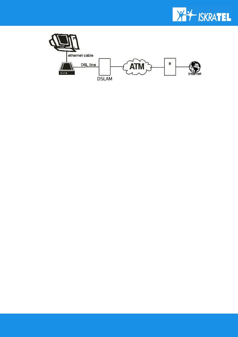
Your SI2000 Callisto821+ Router can also be used for high speed Internet connections. The TCP/IP standards, most commonly used for using the Internet, are supported by the router. The PPPoE connections in dial-up or dial-in mode are also possible. In order to use your SI2000 Callisto821+ Router for Internet access, there must be a DSLAM installed at a provider company's infrastructure near you. DSLAM is a rack of ADSL line cards that links many customer ADSL connections to a single high speed ine. A typical Internet access application is shown below on figure 2.
You can also use NAT (Network Address Translation) services that your SI2000 Callisto821+ Router provides when setting up an Internet connection. This feature allows multiple users on LAN to use the Internet connection, basing on one IP address. The DNS server and DNS relaying is also supported.
6/107
SI2000 Callisto821+ Router Users Guide
Figure 1: Example of Internet access connection
1.2.2Security
Connecting your computer to the Internet exposes it to a wide range of risks. The SI2000 Callisto821+ Router comes with security functions to safeguard your system and data. Three types of interfaces can be controlled by the Firewall: Internal (LAN), external (WAN) and DMZ (DeMilitarized Zone). A DMZ is usually used by a company that wants to host its own Internet services without sacrificing unauthorized access to its private network. Typically, the DMZ contains devices accessible to Internet traffic such as HTTP, FTP, DNS and SMTP servers. You can configure the Firewall to allow or block access from one interface type to another interface type.
You can configure the Firewall by using a default Security level, by Firewall port filters, by Firewall validators and by Security triggers.
1.3 Package contents
SI2000 Callisto821+ Router package comes with following items:
1.SI2000 Callisto821+ Router unit
2.AC adapter
3.Ethernet UTP cord
4.CD-ROM containing user's guide
7/107
SI2000 Callisto821+ Router Users Guide
2 GETTING STARTED
2.1 Installation of hardware
2.1.1Ports
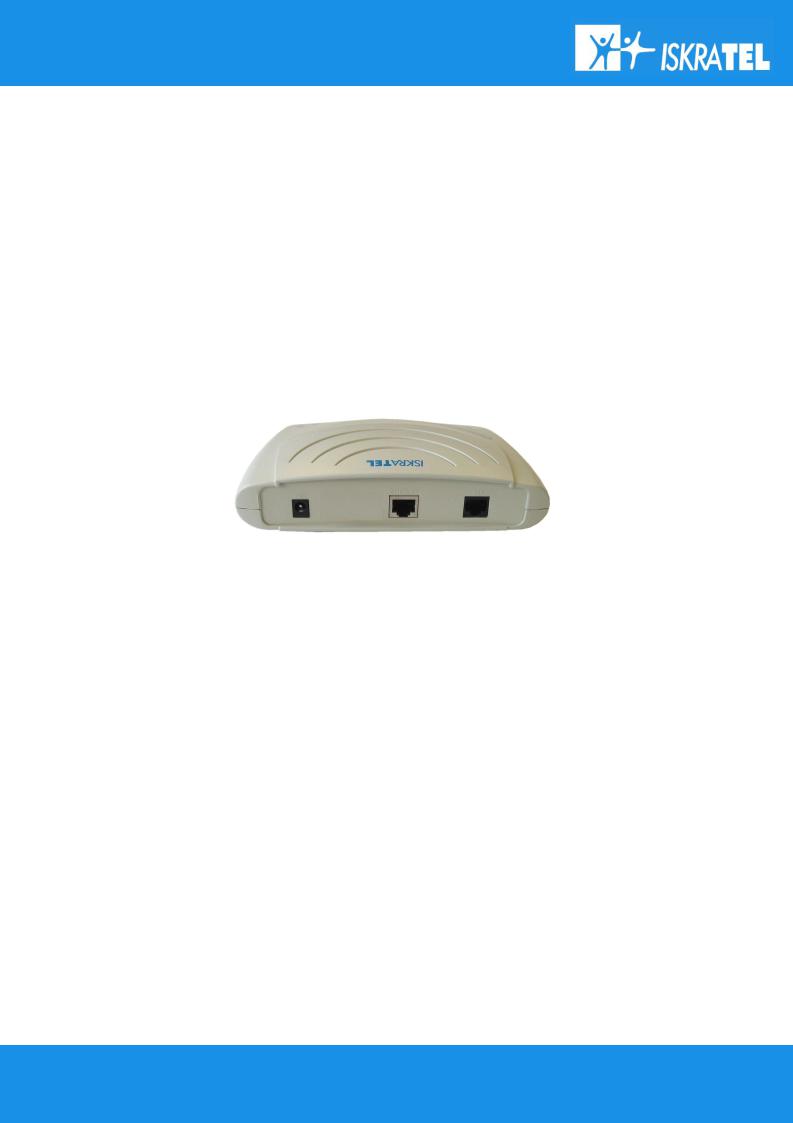
The following figure shows the rear panel of your SI2000 Callisto821+ Router.
Figure 2: The rear panel of the SI2000 Callisto821+ Router
WAN
This port is used for connecting the ADSL cable to your phone jack. Connect the SI2000 Callisto821+ Router to the ADSL port to access the Internet.
RES (Reset button)
This button is used to reset the configuration of the router to factory default values. You must hold this button while the router is starting-up until ALM led will start flashing fast (about 30 seconds). Callisto821+ will use factory default settings only for the time it is running. If you want to preserve factory default settings save the configuration.
Ethernet 10Base-T/100Base-T port
Use a straight-through or crossover ethernet cable (2.1.3Ethernet (UTP) cables) to connect your SI2000 Callisto821+ Router to a computer or any other device. It is possible to manage the settings of the router with telnet connection using this port. The factory setting for IP address is 192.168.1.1.
8/107
SI2000 Callisto821+ Router Users Guide
AC power socket
Plug the power cable to ensure power to the SI2000 Callisto821+ Router.
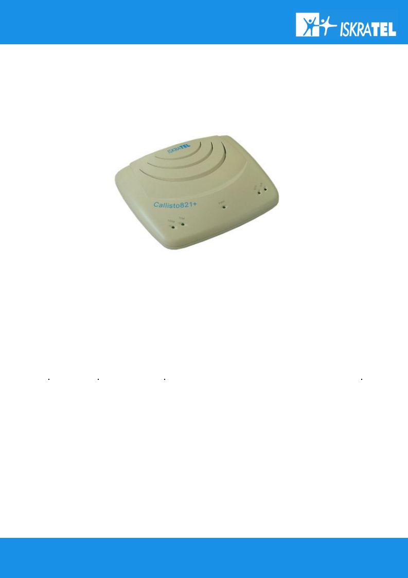
2.1.2Light indicators
Figure 3: The front panel of the SI2000 Callisto821+ Router
The following figure shows the front panel of your SI2000 Callisto821+ Router.
There are five LEDs on the front panel of the router that indicate the status of your SI2000 Callisto821+ Router. The description is given in table 1.
table 1: LEDs description |
|
|
LED |
Status |
Description |
PWR |
on |
Power on. |
|
|
|
|
off |
Power off or fatal malfunction. |
|
|
|
100M/10M |
on |
Ethernet link is established. No ethernet activity. |
|
off |
No ethernet link established. |
|
|
|
|
blinking |
Ethernet activity. |
WAN |
on |
ADSL line is established. |
|
off |
ADSL interface is not functional. |
|
blinking slow |
ADSL interface is in handshake mode looking for DSLAM |
|
blinking fast |
ADSL interface detected DSLAM on the other side and |
|
|
negotiating link parameters. |
ALM |
blinking |
malfunction |
9/107

SI2000 Callisto821+ Router Users Guide
2.1.3Ethernet (UTP) cables
It was earlier mentioned that you should use a straight-through Ethernet cable to connect your SI2000 Callisto821+ Router to a computer directly or use a crossover cable to connect to an external hub. The explanation on what does that mean follows.
There are 8 contacts on UTP connector, described in the next table. The UTP connectors are shown on figure 5 :
table 2: UTP contacts
Contact |
MDI signal |
1 |
TD+ |
2 |
TD- |
3 |
RD+ |
4 |
Not used by 10Base-T |
5 |
Not used by 10Base-T |
6 |
RD- |
7 |
Not used by 10Base-T |
8 |
Not used by 10Base-T |
In case of straight-through cable, the contacts on both sides of the cable are connected in the same way, like shown on the left side of figure 6.
In case of crossover cable, the contacts on both sides of the cable are connected cross-over, like shown on the right side of figure 6.
Figure 5: Ethernet cable: straight-through connected cable (left) and crossover connected cable (right)
10/107

SI2000 Callisto821+ Router Users Guide
2.2 Preliminary setup
2.2.1LAN and TCP/IP setup
This section of the manual provides important information to keep in mind when setting up the first connection between your computer and SI2000 Callisto821+ Router.
The factory default settings of the SI2000 Callisto821+ Router have values listed bellow:
Local IP address: |
192.168.1.1 |
Subnet mask: |
255.255.255.0 |
DHCP server: |
Disabled |
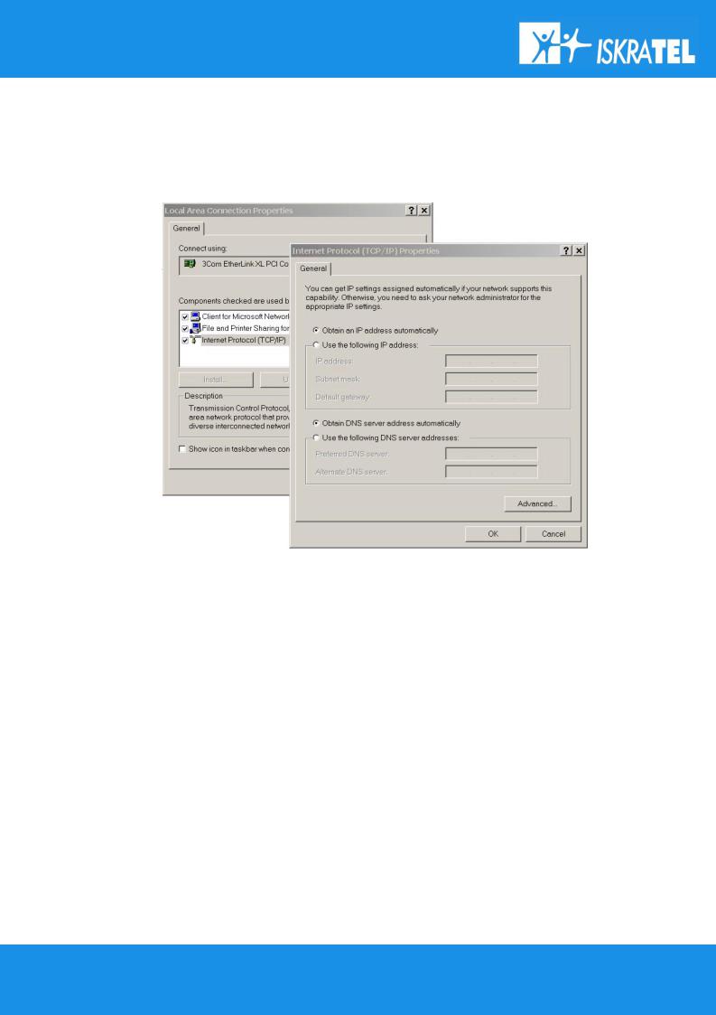
User defined IP address
The default option is to set up the connection by yourself. In this case you must specify the IP address of your system. Be careful that the subnet values of your system and the router are the same, e.g. 192.168.1.0 (IP address 192.168.1.1 for router and IP address 192.168.1.2 for computer). Example is shown on the picture bellow.
The IP address of the router can also be changed, you can learn about that under the 2.2.2Telnet management connection and 2.2.3WEB management connection sections of the Getting started chapter.
11/107
SI2000 Callisto821+ Router Users Guide
Obtain an IP automatically
If you enable DHCP server in Callisto821+, is the easiest way to set up a connection to configure the LAN adapter on your system to obtain an IP automatically. This can be done in your operational system by managing the Local Area Connection Properties. The TCP/IP protocol must be installed on your system and set to obtain an IP address automatically. Example is shown on the figure 7.
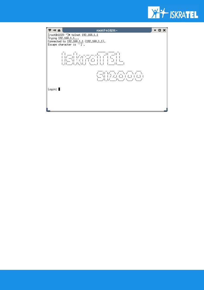
2.2.2Telnet management connection
This section of the document describes the basic principles on how to manage the basic settings of the SI2000 Callisto821+ Router using the Telnet client terminal connection. In order to set up the Telnet Client connection, the router and the computer must reside in the same IP network (e.g. 192.168.1.0).
To establish a Telnet connection do the following:
1.Open the Command Prompt.
2.Type in the command for accessing certain IP address over Telnet Client connection:
telnet <ipaddress>
e.g. telnet 192.168.1.1 for default settings of the SI2000 Callisto821+ Router. 3. The initial screen of Command Line Interface (CLI) will appear:
12/107
SI2000 Callisto821+ Router Users Guide
Figure 8: The initial screen of the CLI window in Telnet Client
To login to the system for the first time, at Login prompt, enter the following user name and password:
Login: admin
Password: admin
To change Local IP address of the router, do next:
Type in the CLI prompt:
ip set interface iplan ipaddress <ipaddress>
where <ipaddress> is the desired IP address, e.g. 192.168.5.123.
Attention! When the IP address of the SI2000 Callisto821+ Router has been changed, the current terminal session in the Telnet management will no longer be possible. You have to establish the new one using the IP address you have given to the Callisto821+.
When changing the IP address of the SI2000 Callisto821+ Router be careful that the subnet values (for example 192.168.2.0 and 192.168.2.) of the Callisto821+ and Personal Computer always stay the same! If that is not the case, the LAN communication between both systems will not be possible. If you have set the IP address with subnet different from the computer ones (the subnet value of the router and the PC do not match) for the router, you have to change the IP settings of the Personal Computer, so that the subnet values will match again!
2.2.3WEB management connection
13/107
SI2000 Callisto821+ Router Users Guide
SI2000 Callisto821+ Router has embedded WEB server included in the firmware. This section of the document describes the basic principles on how to manage the settings of the SI2000 Callisto821+ Router using WEB management connection with any web browser.
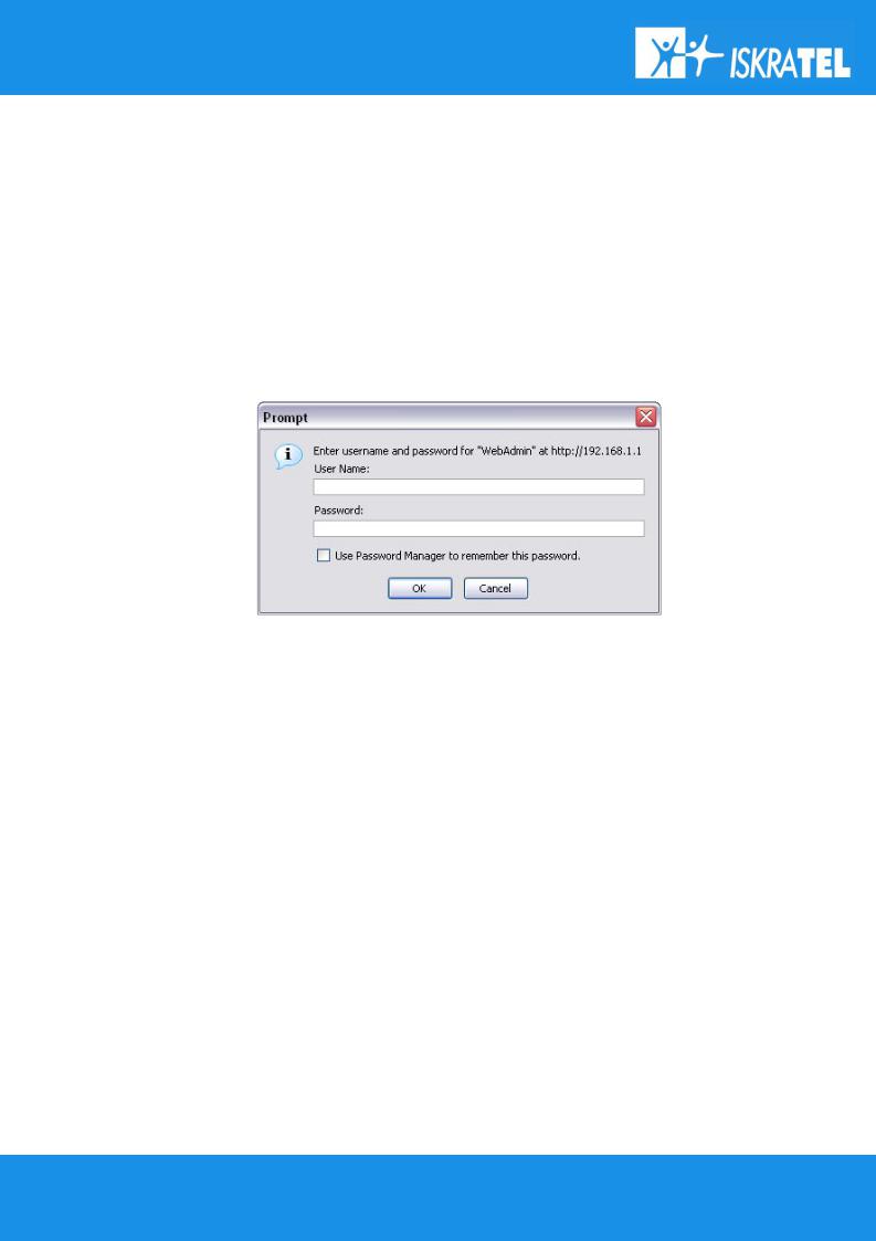
To access Web management connection enter the URL at your web browser:
http://<ipaddress> e.g. http://192.168.1.1
where <ipaddress> is the Local IP address of the SI2000 Callisto821+ Router, e.g. 192.168.1.1 for factory default settings. The IP addresses of router and computer must be parts of the same IP network (e.g. 192.168.1.0).
You are asked to enter username and password:
Enter the user name admin and password admin.
14/107
SI2000 Callisto821+ Router Users Guide
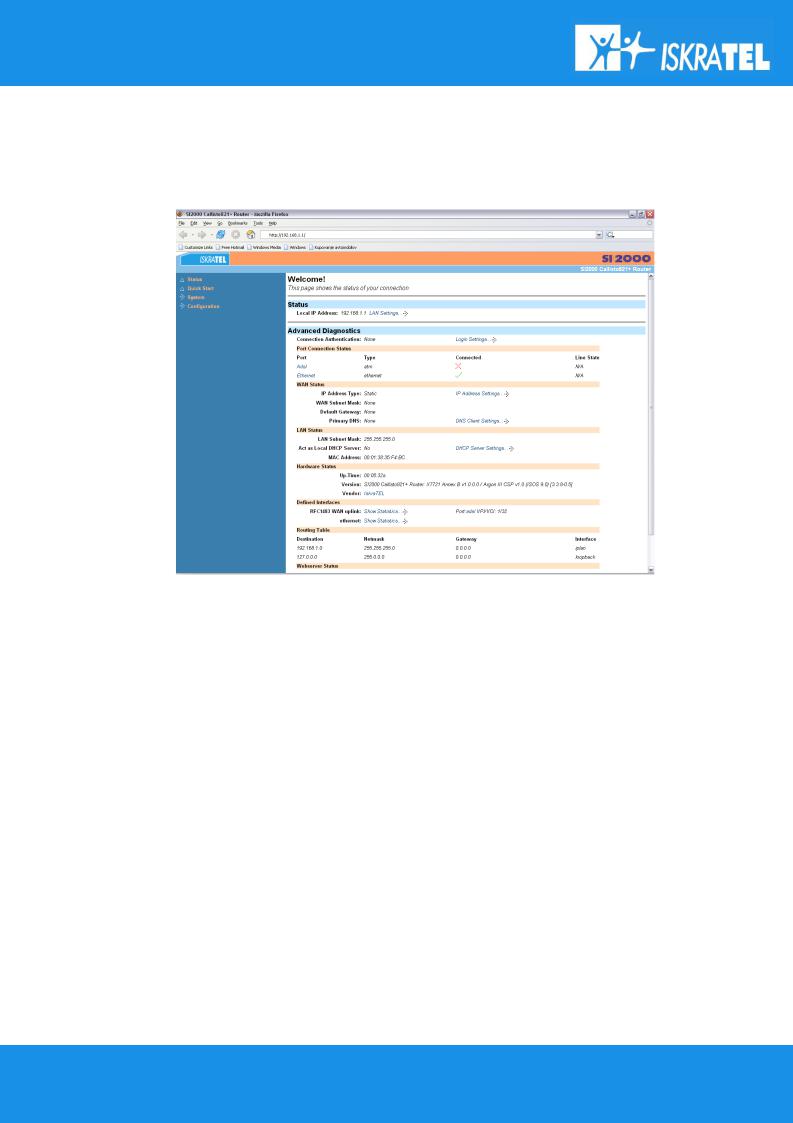
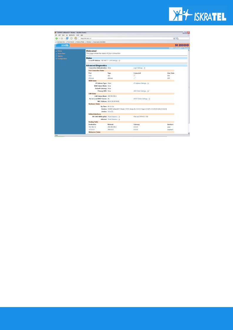
The Status page is displayed:
To change Local IP address of the router, do next:
Click on LAN Settings below Status line in the Status page. The default IP address is not shown in the table that appears. You can edit default IP address by using the Change default LAN port IP address button below. The following page will appear:
15/107
SI2000 Callisto821+ Router Users Guide
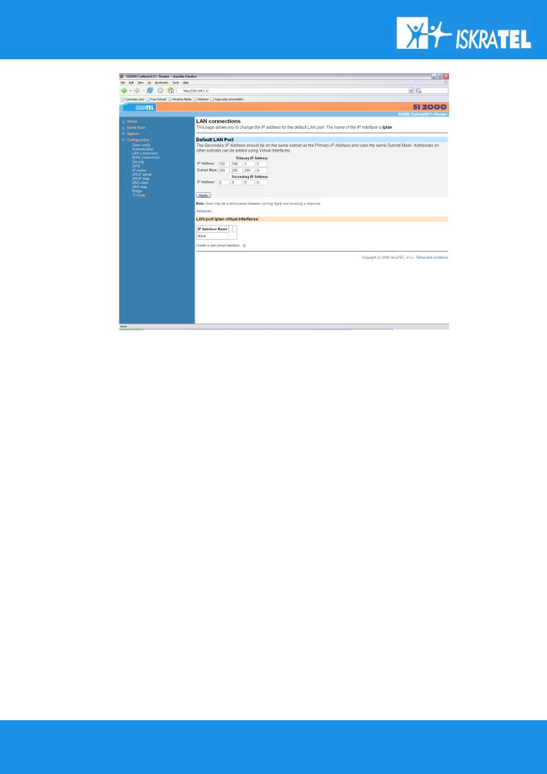
Figure 10: Changing IP address with Web management
Now just type in the desired IP address in the Primary IP Address boxes and click on Apply button. New IP address will be set.
Once you have changed the IP address of the router, make sure that the IP address of computer is a part of the same network!
16/107

SI2000 Callisto821+ Router Users Guide
3 MANAGING SI2000 CALLISTO821+ ROUTER
3.1 Telnet management
Telnet Client uses the Telnet Protocol, part of the TCP/IP suite of protocols, to connect to a remote computer over a network. In order to set up the Telnet Client connection, the router and the computer must be parts of the same IP network (e.g. 192.168.1.0).
The CLI is the Command Line Interface for configuring SI2000 Callisto821+ Router, using the Telnet Protocol.
This chapter provides you with basic CLI description. For further information refer to SI2000 Callisto821+ Router CLI Reference Manual.
3.1.1CLI terminology
In order to use the Telnet Client with the CLI command prompt, you need to understand the following CLI terms:
Transport
A transport is a layer 2 session and everything below it. You can create a transport and attach it to a bridge or router so that data can be bridged or routed via the attached transport. For example, see Attaching a transport to an interface in this chapter. Your SI2000 Callisto821+ Router supports following transports:
-PPPoA
-PPPoE
-RFC1483
-IPoA
-Ethernet
Interface
Bridges and routers both also have interfaces. A single transport is attached to a bridge or router via an interface. For example, see Attaching a transport to an interface in this chapter.
17/107
SI2000 Callisto821+ Router Users Guide
Object
An object is anything that you can create and manipulate as a single entity, for example interfaces, transports, static routes and NAT rules.
List
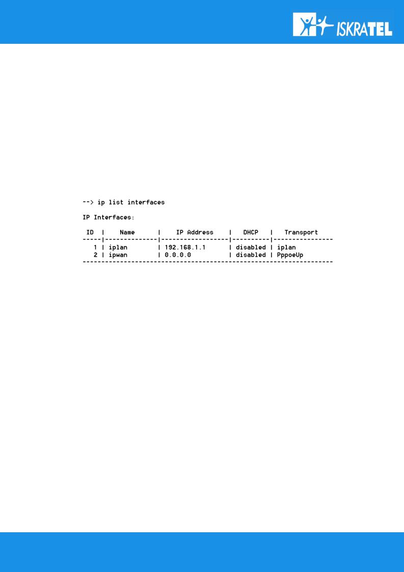
Objects are numbered entries in a list. For example if you have created more than one IP interface, the following command:
ip list interfaces
produces a list of numbered interface objects. Object numbers are displayed in the first column under heading ID. Example is shown in the next figure:
Example: Attaching a transport to an interface
...To attach a transport to a bridge or router, you need to :
1.Create a transport. In the following command, an Ethernet transport is created and named ether1 and the port name is specified (ethernet):
ethernet add transport ether1 ethernet
2.Create an interface. In the following command, a bridge interface is created and called bridgeintf: bridge add interface bridgeintf
3.Attach the transport to the interface. In the following command, the ether1 ethernet transport is attached to the bridgeintf bridge interface:
bridge attach bridgeintf ether1
3.1.2CLI command groups
18/107

SI2000 Callisto821+ Router Users Guide
Your SI2000 Callisto821+ Router has an associated group of commands available in the CLI for configuring the device over Telnet Client. Each command in the group starts with the same command string, e.g. all router configuration commands start with ip. The typical CLI command groups that are embedded in your SI2000 Callisto821+ Router are listed in this chapter along with a simple explanation of the use. The bold and italic part of text is the command string.
ald / Algorithmic dropper
Used for: add, configure and remove ALD profiles
ip / Router configuration
Used for: add, configure and remove IP interfaces.
bridge / Bridge configuration
Used for: add, configure and remove bridge interfaces.
ethernet /Ethernet configuration
Used for: create and remove ethernet transports and provide statistics.
rfc1483 / RFC1483 configuration
Used for: create, configure and remove RFC transports.
ipoa / IPoA configuration
Used for: create, configure and remove IP over ATM transports.
pppoa / PPPoA configuration
Used for: create, configure and remove PPP over ATM server and client transports.
pppoe / PPPoE configuration
Used for: create, configure and remove PPP over ethernet server and client transports.
dhcpserver / DHCP server configuration
Used for: define the DHCP network topology.
dhcpclient / DHCP client configuration
Used for: add, change and remove DHCP client interface declarations.
dhcprelay / DHCP relay configuration
Used for: add and remove DHCP server addresses for relaying.
dnsrelay / DNS relay configuration
Used for: add and remove DNS server addresses.
dnsclient / DNS client configuration
Used for: add and remove DNS client addresses.
igmp / IGMP configuration
Used for: configure igmp behavior for IP stack.
logger / Log to a remote host using syslog
Used for: configure syslog.
security / Security configuration
Used for: enable the security module, create, configure and remove security interfaces and create or configure triggers.
nat / NAT configuration
19/107

SI2000 Callisto821+ Router Users Guide
Used for: enable/ disable NAT (Network Address Translation) objects, create, configure and remove global address pools and reserve mappings.
scheduler / Configuration commands for scheduler
Used for: add and remove scheduler profiles.
sntpclient / DNS client Simple Network Time Protocol Client commands
Used for: add and remove SNTP server addresses.
firewall / Firewall configuration
Used for: create, configure and remove port filters and validators. Control Intrusion Detection.
transports / Transports configuration
Used for: display and delete existing transport configuration details.
port / Port configuration
Used for: configure and display port information.
system / System administration commands
Used for: perform system maintenance tasks.
user / User commands
Used for: add and remove users for accessing the device.
3.1.3CLI conventions
The CLI of your SI2000 Callisto821+ Router uses standard, intuitive command names that can be used in different instances:
add
Use this command to add and name objects (e.g. interfaces or transports). The add command requires attributes to be specified as arguments in a certain order. For example, to create an Ethernet transport, you need to specify the transport name and system port:
ethernet add transport <name> <port>
delete
The delete command deletes named objects or numbered objects, as displayed during using the list command:
ethernet delete transport {<name> <number>}
clear
The clear command deletes all named entities that belong to an object, for example the following command:
20/107
SI2000 Callisto821+ Router Users Guide
firewall clear policies
deletes all of the policy objects that belong to the Firewall. You should use the clear command with caution, as the above example also deletes all validators and portfilters that belong to the policies.
set
The set command changes a value or multiple values within the system, for example:
ip set interface {<name>|<number>} ipaddress <ipaddress>
show
The show command lists current configuration and statistics for an object or module. For example, the command:
bridge show
may give the following response, depending on your bridge configurations:
--> bridge show |
|
Global bridge configuration: |
|
MAC Address: |
0:1:38:2a:9f:bb |
Number of Interfaces: |
4 |
Type: |
TRANSPARENT |
Filter Age: |
300 seconds |
Unicast-Learning: |
HYBRID |
Multicast-Learning: |
HVM |
Interface VLAN ID: |
ENABLED |
Traffic Classes: |
ENABLED |
Tagging: |
ENABLED |
Acceptable Frame Type: |
ENABLED |
Ingress Filtering: |
ENABLED |
VLAN Bridge Configuration: |
|
VLAN Version Number: |
1 |
Maximum VLAN ID: |
4094 |
Maximum Number of VLANS: |
20 |
Current Number of VLANS: |
1 |
figure 13: Example of show command.
3.1.4Help with completing CLI commands
You can tab-complete unique keywords in CLI commands. For example, if you type the first few characters of a keyword in a command, then press [Tab] key:
21/107

SI2000 Callisto821+ Router Users Guide
bridge s [Tab]
and the keyword is automatically completed:
bridge show
If you type a command keyword and want to find out what the next syntax options are, type ‘[Spacebar]?’. For example:
bridge ?
which displays a list of valid keywords that you can use after bridge:
add |
Add an |
interface/VLAN/FDB entry/egress interfaces. |
|
attach |
Attach |
an |
interface with a transport. |
clear |
Clear interfaces/VLANs/FDB entries/egress interfaces. |
||
delete |
Delete |
an |
interface/VLAN/FDB entry/egress interface. |
detach |
Detach |
an |
interface from the transport it is attached |
to. |
|
|
|
flush |
Flush all |
the dynamic entries for an interface. |
|
list |
List interfaces/VLANs/FDB entries/egress interfaces. |
||
set |
Set bridge/interface level parameters. |
||
show |
Show interface/VLAN/FDB entry/egress interface. |
||
figure 14: A list of keywords that you can use after the bridge command.
You can also enter
help
which will display some general help information about the CLI.
3.1.5User accounts
Admin is the only user account which is set up on the system by default. An admin user has super-user level access, so you can create new user accounts and access permissions from this account.
To login to the system using admin username do as follows:
Login: admin
Password: admin
To log out of the system, enter the command:
user logout
and the initial screen of the CLI management will appear.
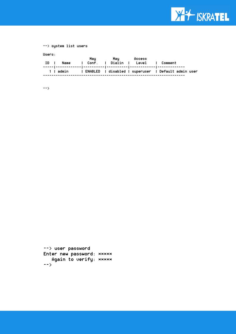
To display the information about the user accounts enter in the CLI prompt line:
system list users
22/107
SI2000 Callisto821+ Router Users Guide
and the following information is returned:
figure 15: The list of user accounts in the CLI system.
Adding new users
There are two types of users that you can add to the system:
1.1 a user that can access the system using dial-in connection, for example, using PPP connection.
To add dial-in user account, use the command:
system add user <name> [''comment'']
e.g. system add user tritonuser ''dial-in user access''
1.2 a login user who can login to the system via a Telnet connection or WEB managment.
To add login user account, use the command:
system add login <name> [''comment'']
e.g. system add login tritonmng ''login user access''
User passwords
To change the password for the user you are currently logged in as, use the command:
user password
and then enter the new password twice as the figure shows:
figure 16: Changing user account password.
To change the password for a different user, enter the command:
user change <name>
23/107

SI2000 Callisto821+ Router Users Guide
and the system will log you on as another user (<name>). Then you can use the user password command to change the password of the desired user. Note that only admin user can use the user change command!
Changing user settings
You may switch between one of the two types of user account (dial-in or login user), or enable both types of user account. In order to do so you can use one of the next two commands. Once again, only the admin user is allowed to change user settings.
To enable/disable the dial-in option for login user, enter the following command:
system set user <name> maydialin {enabled/disabled} e.g. system set user tritonmng maydialin enabled
...To enable/disable the login option for dial-in user, enter the following command:
system set user <name> mayconfigure {enabled/disabled} e.g. system set user tritonuser mayconfigure enabled
3.2 WEB management
Configuring your SI2000 Callisto821+ Router using WEB management has the same effect as configuring it using Telnet Client with CLI but on many occasions it is much easier to do that using WEB management. Throughout this chapter, you will see references to the Command Line Interface (CLI) commands that provide the same functionality as the WEB management.
3.2.1About WEB management
To access WEB management on your SI2000 Callisto821+ Router, you have to make sure that your Callisto821+ router and the computer with ethernet adapter, with which you are connecting to the router, are parts of the same network. How to establish your first connection is described in the Preliminary setup part of the manual, in the WEB management connection chapter.
WEB management provides a series of web pages that you can use to setup and configure your SI2000 Callisto821+ Router. These pages are organized into four main topics. You can select each of the following topics from the menu on the left hand side of the main window, which is shown in figure 17:
24/107
SI2000 Callisto821+ Router Users Guide
figure 17: The main window of WEB management pages.
Status
Offers information about the current setup and status of the system.
Quick start
Allows you to set up some authentication and login details which may be required by your ISP.
System
Offers information about the system hardware and options or how to upgrade the firmware and restart the system.
Configuration
Offers information about the current configuration of various system features with options to change configuration.
Note that the exact information displayed on each web page depends on the specific configuration you are using and that the following sections can give you only a general overview of the setup and configuration details.
25/107

SI2000 Callisto821+ Router Users Guide
3.2.2Status page
The status page contains information about the current configuration of your SI2000 Callisto821+ Router. It provides an overview of the current session configuration. The page consists of the following sections:
Status
The Staus section displays the following items:
•PPPoE Connection status (connected or disconnected) and the time of duration of the current connection.
•the current WAN IP Address configuration. It also provides a WAN settings hyperlink that allows you to create, modify or delete your WAN configuration.
•the current Local IP Address configuration. It also provides a LAN Settings hyperlink that allows you to create, modify or delete your LAN configuration.
Advanced Diagnostics
The Advanced Diagnostics section displays the following items:
•Connection Authentication details. These are details about your current ISP login settings. It also provides a Login Settings hyperlink that allows you to create, modify or delete your existing login setup.
•PPPoE Dial-On-Demand status. This displays whether you can dial to the system using PPPoE. The IP address of PPP server is also displayed.
Port Connection Status
The Port connection status section displays the following items about your port connections:
•Port. List of the ports available on your SI2000 Callisto821+ Router.
•Type. Displays the kind of traffic that can be transported on each port.
•Connected. Informs you which of the ports on your SI2000 Callisto821+ Router are currently connected:
represents the port that is currently connected. represents the port that is currently disconnected.
•Line State. Information about connection status.
WAN Status
The WAN status section displays the following status information about your WAN configuration:
•IP Address Type. Whether the WAN IP address is used or the address is obtained dynamically from DHCP server.
•WAN Subnet Mask.
•Default Gateway. Whether the DHCP server has been configured to give out the WAN IP address as the default Gateway address.
•Primary DNS. Whether a Primary DNS IP address has been set.
The WAN status section also provides two hyperlinks:
•IP Address Settings. This hyperlink allows you to create, modify or delete your WAN configuration.
•DNS Client Settings. This hyperlink allows you to create, modify or delete your DNS Client configuration.
26/107

SI2000 Callisto821+ Router Users Guide
LAN Status
The LAN status section displays the following status information about your LAN settings on SI2000 Callisto821+ Router:
•LAN Subnet Mask.
•Act as Local DHCP Server (Yes/No).
•Link to DHCP server settings
•MAC Address. The actual MAC address for the Ethernet block in the communications processor which is used in your SI2000 Callisto821+ Router is being displayed.
Hardware Status
The Hardware status section displays the following information about your SI2000 Callisto821+ Router:
1.Up-Time. Displays the length of time (in hours:minutes:seconds) that your current session has been connected for.
2.Version. Information about the Firmware release version which has been used to build the image running on your SI2000 Callisto821+ Router.
3.Vendor. Displays the name of the Vendor supplying your SI2000 Callisto821+ Router. The Vendor is IskraTEL.
Defined Interfaces
The Defined Interfaces section lists LAN and WAN interfaces that have been defined on your SI2000 Callisto821+ Router.
Each interface listed has a Show Statistics hyperlink associated with it. Click on this for detailed information about some/all of the following (depending on the interface type and configuration):
•the interface
•connection details
•port configuration
•service parameters
3.2.3System page
The System menu contains options which describe the SI2000 Callisto821+ Router and allow low-level changes to be made, such as updating the image on the system. From the left-hand menu, click on System. The following sub-headings are displayed:
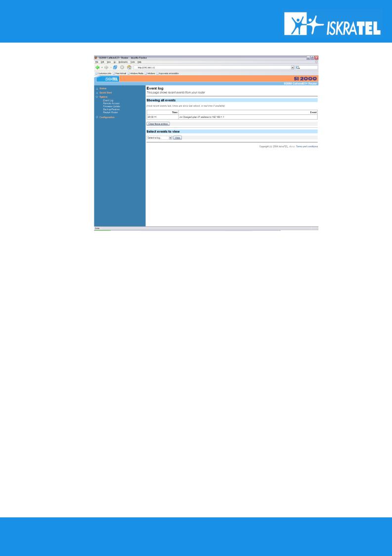
Event Log
The Event Log page is automatically displayed when a configuration error occurs. From the System menu, click on Event Log. The following page is displayed:
27/107
SI2000 Callisto821+ Router Users Guide
Figure 20: The System Error Log page.
On the page there is a table displayed, containing all configuration errors experienced by your SI2000 Callisto821+ Router during a current session. The table also tells you:
•when the error occurred (in seconds since your system was restarted).
•which process the error occurred in.
•brief descriptions of the Error
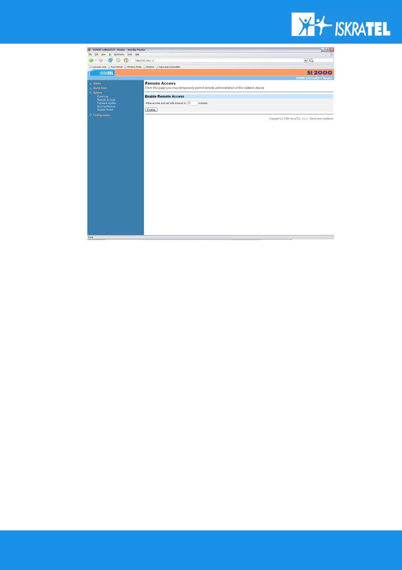
Remote Access
This option allows you to enable temporary remote access to your SI2000 Callisto821+ Router using Network Address Translation (NAT).
Attention! In order to configure remote access, you first need to enable the firewall and create an external to internal firewall policy. For more information, see Security section.
Once you have configured your Security do as follows to enable Remote Access:
1. Click on Remote Access from the System menu to display the following page:
28/107
SI2000 Callisto821+ Router Users Guide
figure 21: The Remote Access page.
2.Type in the length of time that you want to allow remote access for. Click on Enable.
3.The Remote Access page is displayed, confirming the number of seconds remaining for remote access. There is also a Disable button that allows you to stop remote access before the specified time ends.
Firmware Update
This option allows you to upload firmware images to the SI2000 Callisto821+ Router using HTTP. An .tar archive is uploaded to the RAM of your SI2000 Callisto821+ Router. The archive is unpacked automatically, files are validated and then written to Flash memory. The details are described in the chapter 3.5.1Upgrade.
Attention! Be sure that the SI2000 Callisto821+ Router always has power supply during the Update in progress. Interruptions of power supply during Update may severely damage your Callisto821+ router and you will have to contact your Dealer or Product service. See 10.1Recovery mode for troubleshooting in case of malfunctions.
Backup / Restore
This option allows you to backup the configuration on your SI2000 Callisto821+ Router to the computer and then restore it from the same place. The details are described in the chapter 3.4.1Backup / Restore.
Restart Router
This option allows you to restart your SI2000 Callisto821+ Router. The details are described in the chapter
3.4.2Restart.
29/107
SI2000 Callisto821+ Router Users Guide
3.2.4Configuration page
The Configuration menu contains options for configuring features on SI2000 Callisto821+ Router including basic LAN and WAN connections and DHCP and DNS settings.
Attention! Most of the features contain sensible default settings. You are unlikely to have to reconfigure every feature included in the Configuration menu.
From the left-hand menu, click on Configuration. The following sub-headings are displayed:
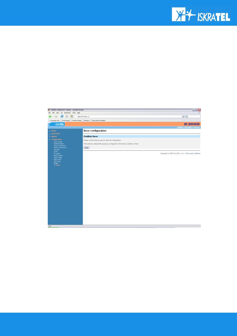
Save Configuration
This option allows you to save your current configuration to flash memory:
1. From the Configuration menu, click on Save config. The following page is displayed:
figure 22: The Save configuration page.
2.Click on the Save button to save your current configuration in the im.conf file in FlashFS. The Save button has the same effect as typing the following CLI command:
system config save
30/107
Loading...