

Page 1
FLAME MONITORING SYSTEM
MODELS S550B, S552B and S556B VIEWING HEADS
OPERATION AND APPLICATION MANUAL
WORLD LEADER IN FLAME MONITORING
Page 2

IRIS S55XX SERIES VIEWING HEADS APPLICATION MANUAL
TABLE OF CONTENTS
INTRODUCTION � 3
DIFFERENCES BETWEEN THE S550B AND S550 ........................................................................ 3
SIGNAL PROCESSOR COMPATIBILITY ......................................................................................... 3
MODEL S550B GENERAL DESCRIPTION ...................................................................................... 3
MODEL S552B GENERAL DESCRIPTION ...................................................................................... 4
FIGURE 1: WIRING TERMINATION DIAGRAM ............................................................................ 4
MODEL S556B GENERAL DESCRIPTION ...................................................................................... 4
VIEWING HEAD WIRING ................................................................................................................. 4
VIEWING HEAD INSTALLATION.................................................................................................... 5
FIGURE 2: CONNECTOR WIRING ................................................................................................... 6
SIGHT PIPE ..........� 7
PURGE AIR ..........� 7
VIEWING HEAD SIGHTING ............................................................................................................. 7
IR DETECTOR .....� 8
UV DETECTOR ...� 8
ORIFICING ..........� 9
DEFAULT SETTINGS FOR THE S550B ............................................................................................ 9
STORED VIEWING HEAD SETTINGS ........................................................................................... 10
ASSIGNING SETTINGS TO CHANNELS A AND B ...................................................................... 10
USING TWO VIEWING HEADS ON THE P520/P522 ................................................................... 10
BEFORE MAKING ADJUSTMENTS ..............................................................................................10
CALIBRATING THE S550B ............................................................................................................. 10
EXAMINING THE RESULTS OF GAIN SETTINGS FROM CALIBRATION .............................. 11
CHECKING OR CHANGING UV GAIN ......................................................................................... 11
CHECKING OR CHANGING THE IR FILTER ............................................................................... 12
CHECKING OR CHANGING IR GAIN ........................................................................................... 12
MANUAL SETUP OF THE S550B ................................................................................................... 12
RETURN TO DEFAULT SETTINGS ................................................................................................ 13
CONTACT INFORMATION ............................................................................................................. 13
FIGURE 3: VIEWING HEAD DIMENSIONS .................................................................................. 14
FIGURE 4: IR VIEWING HEAD LOCATION ................................................................................. 15
FIGURE 5: UV VIEWING HEAD LOCATION ................................................................................ 15
FIGURE 6: SIGHTING OPPOSED FIRED BURNERS .................................................................. 16
FIGURE 7: VIEWING HEAD MOUNTING ..................................................................................... 16
FIGURE 8: S550B PROGRAMMING FLOWCHART ..................................................................... 17
FIGURE 9: S552B PROGRAMMING FLOWCHART ..................................................................... 18
FIGURE 10: S556B PROGRAMMING FLOWCHART ................................................................... 19
PAGE 2
Page 3

IRIS S55XX SERIES VIEWING HEADS APPLICATION MANUAL
INTRODUCTION
For the sake of simplicity, only the operation of the
S550B viewing head in combination with the P522
signal processor will be described in detail. The
S552B and the S556B will be discussed separately in
their respective sections.
The S550B, S552B and S556B can be used with
IRIS Models P531, P532 and later versions of the
Model P520 and P522 signal processors. Refer to
the respective processor manual for connection and
operation not described in this manual.
DIFFERENCES BETWEEN THE S550B AND S550
The Model S550B is basically the same in operation
as the earlier S550, except that a two line numeric
readout replaces the two color LED for displaying
and monitoring the UV and IR count rates. The displayed value is the pulse rate divided by 100.
The S550B provides an additional analog output that
can be measured as a current to ground. This can be
achieved by placing a 1000 ohm resistor in series with
the shield and the SGND terminal on the processor,
and monitoring the voltage across the resistor.
If the internal temperature of these viewing heads exceed 70° C, the temperature will be displayed once
every four seconds.
P522 AC signal processors. Some earlier manufactured P522 units may require an upgrade. All P531
and P532 signal processors are fully compatible with
these viewing heads.
Note: Source impedance resistors, 470 Ohm 1/4
Watt must be installed between SC and SGND for all
cable runs between 300 and 700 ft. from the signal
processor to the viewing head.
MODEL S550B GENERAL DESCRIPTION
The IRIS Model S550B is a dual channel, state-ofthe-art flame monitoring viewing head capable of
monitoring both the UV (ultraviolet) and IR (Infrared) components of a flame. This is accomplished by
utilizing two types of detectors, an IR solid state sensor and a UV Photo detector, together with a unique
dichroic beam-splitting mirror.
The S550B produces output pulse rates proportional
to the flame signal strength; the pulse rates are displayed at the front panel of the signal processor, and
at the rear of the viewing head. The S550B uses a
two line digital readout which displays the pulse rate
divided by 100. The upper readout displays the UV
count in green digits, and the lower readout displays
the IR count in red. This information can readily
be used to achieve maximum flame signal strength
while aiming and sighting the viewing head.
If the digits “99” are displayed, this indicates that the
IR sensor is saturating. Either reduce the IR “analog”
gain or install an orifice disc. (The IR analog gain is
the first digit of the IR gain).
The IR gain should be set so that the displayed
count is well below the saturation point (34 at the
viewing head, or 3400 at the signal processor) at
maximum firing rate. The signal processor and the
viewing head are designed to “Fail Safe” (Show
“No Flame”) in case of saturation. This may also
cause the pulse counter to start from zero, causing
the flame relay to de-energize.
In some applications, an orifice disk may be required
to discriminate between background radiation and
main flame. See ORIFICING on page 9.
SIGNAL PROCESSOR COMPATIBILITY
Viewing heads described in this manual are compatible with currently manufactured P520, P522 DC and
Certain parameters in the S550B, S552B and S556B
viewing heads can be selected or adjusted remotely
from the front panel of the signal processor. These
parameters are:
a) UV gain 0-99
b) Filter Selection 1: 16Hz
2: 24Hz
3: 33Hz
4: 52Hz
5: 75Hz
6: 100Hz
7: 155Hz
8: 215Hz
c) IR gain 0-699
Once adjusted, the new parameters are stored in an
EEPROM in the signal processor. If power is re-
PAGE 3
Page 4
IRIS S55XX SERIES VIEWING HEADS APPLICATION MANUAL
WIRING SIDE VIEW - COVER REMOVED
CONNECT SHIELD
TO TERM 3
USE SHRINK TUBING
RED
GREEN
BLACK
WHITE
SHIELD
+V
GND
SC
SIG
GND
SIG
+24VDC
GND
SELF
CHECK
GND
SIGNAL
moved from the signal processor, which powers the
viewing head, and then reapplied, the signal processor automatically re-sends the stored parameters
to the viewing head. In addition, at the front panel
of the signal processor the operator may also select
“CAL”, a semi-automatic mode which will help to
speed up the setup. This is explained in detail in the
section CALIBRATING THE S550B , and further
illustrated in FIGURE 8: S550B PROGRAM-
MING FLOWCHART.
The S550B can be described as a dual-sensor viewing
head where the gain and filter selections are adjusted
and stored remotely by the signal processors to which
it is connected.
MODEL S552B GENERAL DESCRIPTION
The S552B viewing head is designed for IR sensing
only. It is basically an S550B without the UV capability, and a single line display. The IR pulse rate is
displayed in Red. The Signal Processor detects and
identifies the viewing head model to which it is connected, and will only allow adjustments related to that
model to be performed. In the Model S552B, these
adjustments are:
in FIGURE 9: S552B PROGRAMMING FLOW-
CHART,
MODEL S556B GENERAL DESCRIPTION
The S556B viewing head is designed for UV sensing
only. It is basically an S550B without the IR capability. The Signal Processor detects and identifies the
viewing head model to which it is connected, in this
case the model S556B, and will only allow adjustments related to that model to be performed. In the
Model S556B, this adjustment is:
a) UV gain 0-99
In addition, features such as CAL are limited to the
features of the attached viewing head, in this case the
S556B. These features are further illustrated in the
S556B PROGRAMMING FLOWCHART, shown in
Figure 10 on page 19.
VIEWING HEAD WIRING
Viewing heads are wired to the appropriate terminals
located on the bottom of the P522, P531 and P532
signal processors, and on the terminals located on the
rear PC Board of the P520. These terminals are listed
functionally in the table below.
a) Filter Selection 1-8
b) IR gain 0-699
In addition, features such as CAL are limited to the
features of the attached viewing head, in this case
the S552B. These features are further illustrated
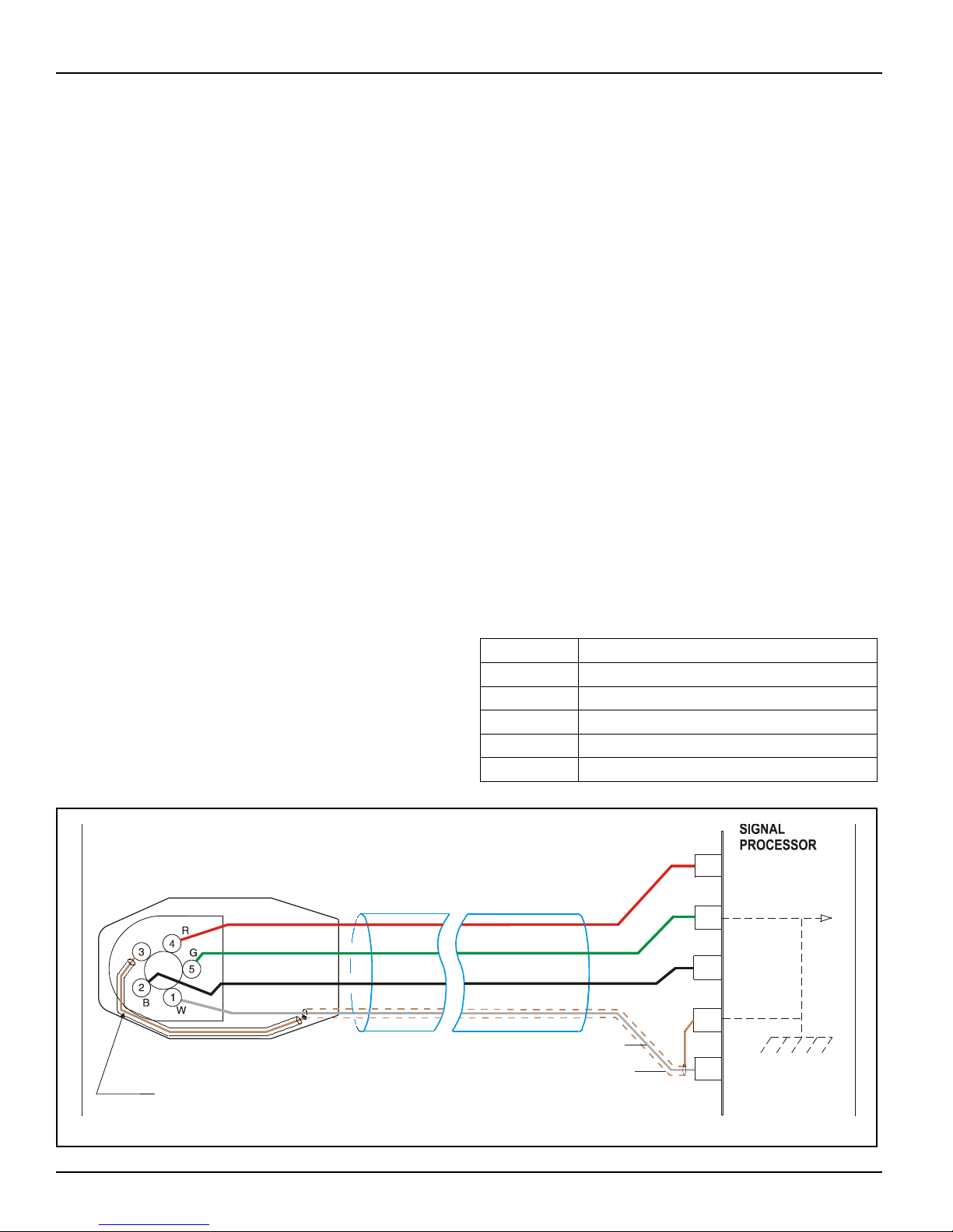
TERMINAL DESCRIPTION
GND Power Ground
+V +24VDC Power to Viewing Head
SC Shutter Drive Signal to Viewing Head
SIG Flame Signal from Viewing Head
SIG GND Signal Ground
FIGURE 1: WIRING TERMINATION DIAGRAM
PAGE 4
Page 5

IRIS S55XX SERIES VIEWING HEADS APPLICATION MANUAL
The diagram in Figure 1 shows the wiring of the viewing head connector to the signal processor using the
recommended IRIS type C328 cable. This cable has a
UL ITC rating and can be used in the US in hazardous
locations. Note that the flame signal wire is shielded,
and that the shield is terminated at both ends.
The shield is used as the signal ground wire which
goes to terminal SIG GND on the signal processor,
and to pin 3 on the viewing head plug. The shield
must be a braided type for this application in order to
maintain an electrical path. For this reason, a foil type
shield should not be used. This signal ground shield
is also the self-checking or shutter drive circuit return
path. It is recommended that the IRIS C328 cable be
used for all applications.
Connection of the IRIS type C328 cable to the viewing head plug is shown on the following page in FIG-
URE 2, CONNECTOR WIRING, and should be
done as follows:
Remove the cable entry nut from the plug housing.
Remove the rubber grommet and flat sealing washer.
With a pair of long-nosed pliers remove the center
ring only of the rubber grommet.
1. Strip 2 inches of the cable outer cover from the
cable removing any cellophane wrap or filler
material. Strip the insulation from the shielded
wire (if insulated over shield) a full 2 inches to
expose the shield.
2. Slide the shield back until a bulge develops close
to where the wire exits the cable outer covering.
3. Carefully spread a few strands of the shield at
the bulge (making sure not to break any strands)
to create an opening and pull the wire out of
shield through opening.
4. Carefully return shield to original shape and
length by pulling gently, then cover the shield
with heat shrink tubing to insulate it.
5. Slide the nut (with threads toward the cable end),
the washer and the grommet approximately six
inches onto the cable.
6. Slip the cable through the bottom opening of the
connector making sure that the cable outer jacket
is secure under the cable clamp and tighten the
two screws on the cable clamp.
7. Reassemble the grommet, flat washer, and cable
entry nut and tighten.
8. Strip each wire 3/8” as shown in the assembly
drawing figure 2 on the following page.
9. Proceed to wire the connector as follows: (Refer
to the wiring diagram figure 1 for terminal locations.)
Connect the viewing head signal wire (the shield-
ed wire) WHT to terminal No. 1 by inserting
into opening and then tightening the retaining
screw.
Connect the self-checking signal wire BLK to
terminal No. 2.
Connect the signal ground shield from WHT wire
with shrink tubing to terminal No. 3.
Connect the + 24VDC power wire RED to termi-
nal No. 4.
Connect the power ground wire GRN to terminal
No. 5.
Assemble the back of the plug and insert the
jackscrew through plug assembly.
The cable at the signal processor end should be prepared
in a similar way to the plug end, particularly the shield
from the WHT wire. Follow the wiring connections as
shown in the wiring diagram figure 1, making sure that
the shield does not touch the other adjacent terminals.
VIEWING HEAD INSTALLATION
Before beginning the actual installation, determine
the best location for mounting the viewing head based
upon the following factors:
PRESSURE: The viewing head lens will with-
stand 5 psi. If the lens assembly is exposed to
greater than 5 psi through the sight pipe, then
an isolation unit must be used. An IRIS isolation unit with purge air entrance model ISO/
Unit is available as an accessory.
TEMPERATURE: The viewing head will with-
stand an ambient temperature to 80° C (176°
F). However, the case temperature of the
housing must not exceed 60° C (140° F).
PAGE 5
Page 6
IRIS S55XX SERIES VIEWING HEADS APPLICATION MANUAL
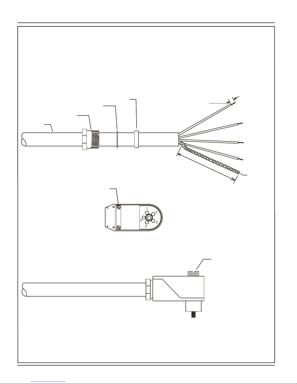
IRIS C328 CABLE
3 CONDUCTORS PLUS 1 COAX
3CONDUCTORS: 16 AWG 19 STRAND INSULATED WITH
CROSSED-LINKED-POLYETHYLENE .017 THK
COLORS: BLACK-RED-GREEN
1 COAX: 16 AWG 19 STRAND INSULATED WITH
CROSSED-LINKED-POLYETHYLENE .017 THK
COLOR WHITE
36 AWG BRAIDED SHIELD 90% COVERAGE
WITH .012 THK JACKET COLOR BLACK
CABLED: POLYPROPYLENE FILLERS FOR ROUNDNESS
JACKET: CROSSED-LINKED-POLYETHYLENE
STRIP 3/8" TYPICAL
GROMMET
FLAT WASHER
CABLE ENTRY NUT
SHIELD *
CABLE
PREPARATION
1
3
/
4
"
(
T
Y
P
)
CABLE
CABLE CLAMP
CONNECTOR WITH
REAR COVER REMOVED
INSULATE SHIELD WITH SHRINK
TUBING LEAVING 3/8" STICKING OUT
CONNECTOR JACKSCREW
FINAL ASSEMBLY
* CABLE IS SHOWN WITH SHIELD
ALREADY REMOVED FROM WHITE WIRE
PAGE 6
FIGURE 2: CONNECTOR WIRING
Page 7

IRIS S55XX SERIES VIEWING HEADS APPLICATION MANUAL
Purge air will help reduce conducted heat
through the sight pipe and flange. A heat insulating ultem nipple (IRIS part R-508-12) will
reduce will reduce this conducted heat, but
direct radiation can cause housing case temperature to exceed limits. If the ambient heat
(direct radiation) is excessive, then a fiber optic extension should be considered. This uses
a fiber optic cable between the sight pipe and
the viewing head, allowing the viewing head
to be placed further away form the heat source.
Refer to the Fiber Optic Manual, or the IRIS
web site for more information.
The model S550 and S55XB series of viewing
heads have in place a sensor for sensing the
internal temperature of the head. To access
the reading of the viewing head temperature,
press the “Reset” and the “Down” arrow key
at the same time. The temperature reading will
be displayed in the four-digit readout. The
reading (indicated in °C) will disappear and
the normal reading will continue after several
seconds.
VIBRATION: Do not install the viewing head
where it could be subject to vibration. A vibrating IR sensing viewing head can simulate
flame when viewing a glowing background.
Provide an anti-vibration mount if excessive
vibrations are present.
CLEARANCE: Make sure there will be suffi-
cient room to remove the viewing head housing for servicing.
SIGHT PIPE
A minimum two inch diameter black iron pipe together with a swivel mount is recommended for use with
all IRIS viewing heads. IRIS manufactures a range of
swivel mounts, both pipe thread or flange mounting.
See the IRIS ACCESSORY CATALOG on the User
Manuals CD, or view it on the IRIS web site.
PURGE AIR
Use a flexible air supply line, to allow for repositioning of the viewing head and sight pipe until a final and
permanent position has been decided. A continuous
flow of air must be maintained in order to keep the
viewing cool and the sight pipe clean. At least three
CFM at approximately eight inches of water column
above windbox pressure is recommended for each
viewing head. The air supply must be clean, free of
oils and water, and preferably cool.
VIEWING HEAD SIGHTING
The sighting of the viewing head should be parallel
to the center line of the burner in the direction of the
flame. The sight pipe should be mounted as close to
the center line as possible, the idea is to sight along
the flame rather than across the flame. This will help
prevent drop outs of the flame under changing load
conditions. See figures 4 and 5 on page 15
Utilizing a sighting or the sight pipe aimed at the root
of the flame (where the turbulent combustion air mixes with the flame) is a good starting point for optimizing the sighting. Using a swivel mount to “zero-in” on
the highest signal will assure maximum performance.
A typical viewing head installation using a swivel
mount is shown in figure 7 on page 16.
The sight pipe diameter should be large enough to
allow a reasonable field of view, and to allow for adjustment of the swivel mount angle. The S550B has
two angles of view, one for the IR detector, which is
1.0° and one for the UV detector which is about 3.0°;
this translates into a circle of view that varies with the
viewing distance as shown in the following table.
Distance Distance Diameter of
IR View
ft inches inches inches
2 24 .64 1.3
3 36 .73 1.9
6 72 1.45 3.8
12 144 2.9 7.6
18 216 4.35 11.4
Diameter of
UV View
Detecting flame in a sulfur recovery unit can present
a challenge for flicker type flame monitors. The IR
detector will detect natural gas used for the warm-up
of the reactor. Usually the combustion air is turbulent
enough to cause a good flicker signal.
When the sour gas is introduced and the natural gas is
shut down, the flame signal may drop off or drop out
entirely. The reason for this is that there is a complete
change in the flicker content for the existing viewing
PAGE 7
Page 8

IRIS S55XX SERIES VIEWING HEADS APPLICATION MANUAL
head sighting. If this is the case, then optimizing the
flame signal for the sour gas by “zeroing-in” on this
flame, and not the warm-up burner is recommended
Once optimizing the sighting for the sour gas has been
completed, it may be found that the signal level is too
low on the natural gas. In this case, using the UV detector for this application may be required. It may be
necessary to use two sets of set points for flame ON
and flame OFF, one set for proving and detecting the
natural gas flame and the other for proving and detecting the sour gas flame. The switch-over from Channel
A to Channel B should be done when removing the
natural gas burner. This can be implemented from the
burner control system. This switch-over and the use
of Channels A and B with their independent settings
is explained in the section “ASSIGNING SETTINGS
TO CHANNELS A AND B” on page 9.
IR DETECTOR
The IR detector responds to flicker content in the
flame. Flame flicker is caused by the combustion, or
forced air injected into the flame. This combustion air
can be mixed with the fuel (pulverized coal) or can
be introduced separately. In either case, forced air at
high velocity is introduced in such a way as to aid the
combustion process. This air is usually made turbulent by causing it to swirl with spin vanes located in
the burner barrel.
Flame flicker is created when this turbulent air mixes
with the flame. It is composed of random frequencies from zero Hz to over 2,000 Hz. The amount of
high frequency flicker (above 200 Hz) is dependent
on the fuel and burner. The amplitude of the flicker
frequencies always follows an exponential curve with
zero frequency having the highest amplitude and the
higher frequencies the lowest. The amplitude level of
the higher frequencies is usually 40dB down (factor
of 100) from zero Hz or DC.
The S550B and S552B viewing heads respond to flicker frequencies 16 Hz and above. The lower frequencies
are ignored so it is important to sight the viewing head
on the highly turbulent portion of the flame that contains these higher frequencies. The location of these
higher frequencies can be predicted by examining the
burner with regard to where the flame envelope begins
and where the turbulent air enters this flame. This
spot can be chosen by examining the drawings of the
burner but it is better to do this empirically by using a
swivel mount on the viewing head.
UV DETECTOR
The UV Photo Detector in the S550B and S556B viewing heads have a spectral response of 190-215nm. The
output of the detector is a pulse stream of randomly
spaced pulses whose average rate is proportional to the
UV radiation present in the flame.
The very narrow spectral response of this type of
detector makes it ideal for discriminating between
flame and glowing refractory and other burners. However, because the detector responds to only the very
short wavelengths, this radiation is easily absorbed
and masked, for example with pulverized coal, by
unburned fuel or other impurities in the fuel. Sour
gas (H2S) will readily absorb these short 200nm
wavelengths as well as other waste fuels resulting in a
dropout of the flame signal. Even standard glass will
absorb this wavelength, hence, the necessity of using
a quartz lens with these viewing heads.
In general, these viewing heads will work well on
natural gas flames. They will respond to oil flames
but with a lower signal level. The sighting for both
oil and gas flames should be parallel to the axis of the
burner and aimed at the root of the flame, as with the
IR detector. (See previous section “IR DETECTOR”.)
Photographs of gas and oil flames using visual and
UV-sensitive film clearly shows that the UV zone is
much smaller than the visible zone, and the highest
UV intensity occurs near the flame root. In addition,
the zone of higher UV intensity does not overlap the
same zones of adjacent or opposing burners so that,
with proper sighting, discrimination is predictable.
As a general rule, the sighting of the S556B and the
S550B when using the UV detector, will more likely
be a “line-of-sight” than the IR flicker detector which
will read flame signals bouncing off the side of the
sight pipe and other “reflectors”. Sometimes the reading with the IR detectors can be greater with a reflected
signal than the direct line of sight. The UV detector,
on the other hand, will have to be aimed at the part of
flame that has the highest concentration of UV, which
usually is at the root of the flame (at the throat of the
burner) and in a very narrow region. The angle of view
of the S550B UV sensor is somewhat wider than the
S550B IR sensor, but this does not offset the fact that
PAGE 8
Page 9

IRIS S55XX SERIES VIEWING HEADS APPLICATION MANUAL
the UV radiation present is from a very small region.
This small region emitting UV is not the case however, for low NOx gas burners. The UV radiation is
usually much less in intensity and spread out with this
type of burner, and relatively high readings can be obtained from all over the furnace when many burners
are on. This is particularly true when flue gas recirculation is used. There will however, be a relatively
stronger signal near the “root” of the flame and this
more intense spot should be located during the aiming
or sighting process. This “root” or intense spot may be
further out than with the standard gas burner so it is
imperative that a swivel mount be used when making
these sighting adjustments.
Another factor that needs to be considered when
aiming the viewing head, is the load condition of the
boiler. The flames from a burner can be radically different at different loads. This is one of the reasons for
trying to choose a sighting initially that will minimize
this changing flame at different loads. If the flame
extends further out at higher loads then the parallel
to the burner axis sighting will be the most effective.
The use of a large diameter sight pipe with a swivel
mount is recommended for all installations on large
multi burner boilers.
ORIFICING
In some applications, the extreme brightness of the
burner flames can cause the sensors in the viewing
head to saturate. Under these conditions, orificing of
the viewing head sight path will greatly improve the
performance, particularly with regard to discrimination between flames. Saturation is more probable with
large power utility boilers where the burners are very
large and relatively close to one another. If the flame
is bright enough to cause the eye to hurt when looking
at the flame, then orificing should be used. This eye
test applies to incandescent type flames such as oil
and coal but will not be valid for natural gas flames.
the lens. Four orifice discs are available with center
hole diameters of 3/8, 1/4, 3/16 and 1/8 inch. These
discs are installed with retaining rings in the flange at
the edge of the 1/2 inch NPT female pipe thread for
the purge air. An internal type retaining ring is first
installed by positioning a ring in the machined groove
inside flange opening from the housing side. The orifice disc is then inserted. Use a second retaining ring
to hold it in place so that it is sandwiched tightly between the two retaining rings.
Usually an orifice disc with a larger diameter hole is
tried first. There will be a reduction in the signal level
so if the associated viewing head and signal processor
has been previously calibrated, it will be necessary to
calibrate the processor again so that the gain settings
will be correct. If the discrimination is still not satisfactory then an orifice disc with a smaller diameter
hole should be tried.
Generally speaking, orificing should always be considered when the burner(s) are large (50K lbs of steam
and up), particularly when the IR detector is used
which would be the case for oil or pulverized coal.
The following table shows the signal reducing characteristics of the different orifice disks.
Aperture Hole Fn (f Stop) Relative light
passing power
1” 2 1
3/8” 5.3 1/8
1/4” 8 1/16
3/16” 10.7 1/32
1/8” 16 1/64
DEFAULT SETTINGS FOR THE S550B
A new signal processor will set the attached viewing
head default values as follow:
UV Gain = 32 (out of 0-99 range)
Orificing may help improve the discrimination characteristics for the UV detector as well as the IR. The
UV detector is not likely to saturate; however, orificing will usually improve the discrimination ratio for
large size burners.
An orifice disc is simply a metal disc with a circular
hole in the center which is placed directly in front of
Filter = Filter 3 (high pass above 33Hz)
IR Gain = 451 (out of 0- 699 range)
These are nominal settings that should allow for initial sightings and adjustments. Both UV and IR sensors are active in the default mode. If the settings for
the viewing head has been changed from the default
values, they can be reset to the factory default from
PAGE 9
Page 10

IRIS S55XX SERIES VIEWING HEADS APPLICATION MANUAL
the P520 / P522 control panel. (See “RETURN TO
DEFAULT SETTINGS” on Page 13.)
STORED VIEWING HEAD SETTINGS
Viewing Head settings are stored in an EEPROM in
the particular signal processor to which it is attached.
In the event of a power down or power loss, these
settings will be restored upon power up. If an S550B
viewing head is replaced with another, the stored settings will be applied to the replacement. This simplifies field replacements since these viewing heads are
made to close tolerances, and will work virtually the
same as the viewing head it replaced.
ASSIGNING SETTINGS TO CHANNELS A AND B
The P520 and P522 signal processors, when used with
an S550B viewing head, allows assigning one group
of settings to Channel A and another group to Channel B.
If the CHAN SEL input to the P520 or P522 is open or
de-energized, then the Channel A lighted push-button
on the front panel will be ON. If a voltage of 7.5V to
30V is applied across the two CHAN SEL inputs, then
Channel B will be selected and the Channel B lighted
push button will be ON.
When Channel A is selected, any P520 or P522
parameters changed (this includes Flame ON and
Flame OFF set points and the analog gain of the
P520/P522 as well as the gain and filter selection
for the S550B) will be stored for use when Channel
A is selected. Similarly, when Channel B is selected
any P520 or P522 changes are stored for use when
Channel B is selected. When the CHAN SEL input is
changed, the P520/P522 changes the set points in use
accordingly and sends the appropriate gain and filter
selections to the S550B viewing head.
then proceed.
During the process of examining or changing the
S550B settings, with the Channel A and B (NO and
YES) push buttons, the red LED for the channel
which the changes apply to, will be blinking.
A visual check should be made to see which channel
push-button is lighted when the S550B settings are
being reviewed or changed. It is possible to unintentionally get into the S550B CAL modes with the
wrong channel selected.
USING TWO VIEWING HEADS ON THE P520/P522
The P520 and P522 signal processors are capable of
supporting two viewing heads by using the V.H. A
and V.H. B inputs. To achieve this, a 24VDC channel
select signal must be applied simultaneously to the
coil of the VH select relay and to the channel select
input. When the channel selection is changed, the
alternate set of data inputs from viewing head B will
be switched into the signal processor by the VH select
relay and the processor will apply a different group of
set points and gains in response to the A/B Channel
switch.
There are no restrictions on how viewing heads may
be mixed between the two channels. An S550B can
be used on one channel and an S511 on another, or an
S552B on one channel and an S556B on another. It
should be noted however, that only one viewing head
can be active at any given time.
The earlier 500 series viewing heads - Models S506,
S511 and S512 - are not adjustable remotely as the
S550B family of viewing heads are. The P520 or P522
signal processors will continue to work as they have
in the past with an earlier S5XX series viewing head
when the channel with that viewing head is selected.
In the P520 and P522, it is possible to observe and
change settings for the channel which is not selected,
by pressing the other channel push button - it will blink
indicating that the selection is temporary - and then
proceed as if the CHAN SEL input had changed.
This method is available for examining or changing Flame ON and Flame OFF set points and other
settings in the P520 and P522. The same procedure applies to manually changing viewing head
settings when the desired channel is not selected:
press the push-button for the desired channel and
PAGE 10
BEFORE MAKING ADJUSTMENTS
Before making any adjustments to the S550B, the
flame signal strength should be optimized by aiming the viewing head at the most intense part of the
flame as explained in the two previous sections “IR
DETECTOR” and “UV DETECTOR”. This operation
should be done with the default setting
CALIBRATING THE S550B
The calibrate feature is designed to aid with the setup
of the viewing head. It is basically an automatic gain
Page 11

IRIS S55XX SERIES VIEWING HEADS APPLICATION MANUAL
adjustment for the selected sensor; the gain for the
sensor not selected is set to zero. The CAL feature
narrows the displayed count to about 1200, and automatically sets the Flame ON set point to 800 and
the Flame OFF set point to 600. The filter selection
remains unchanged.
Calibration Procedure:
1) Perform a preliminary sighting of the viewing
head, aiming for a high signal strength, as indicated by the digital readout on the S550B. The
upper display will indicate the IR value in red, the
lower display indicates the UV value in green.
2) Ensure that the external input for CHAN SEL
is properly set for the channel about to be calibrated, and that the channel LED is illuminated.
When using the calibrate feature, the option of
working with the channel that is not selected by
the external input is not available.
3) Bring the firing rate of the burner to a low fire
condition.
4) If the flame relay has not yet energized, adjust
the flame on & off set points so that it does. If
“CAL” was activated without the flame relay being energized, the following display will show:
“bon?”. Press the reset button to return to the
previous state.
5) Determine whether to calibrate using the UV or
IR sensor. See the earlier sections on IR DETECTOR and UV DETECTOR. At the front panel of
the P520 or P522 press both A and B push buttons simultaneously.
operation, displaying a reading of 1100 to 1300.
However, if the signal input is too low, the P520/
P522 will display “2-Lo”. Press the RESET button to return to the previous settings. If the signal
level is too high, the display will show “OriF”.
(See the section on ORIFICING on page 9.)
Press RESET to return to the previous settings.
6) If step 5 was successful, re-aim the viewing head
for a final adjustment using the digital readout
to adjust the viewing angle for a maximum
signal strength. The CAL sequence should then
be repeated as in step 5). The Flame Relay will
remain energized. The display should show a
reading between 1100 and 1300.
7) Review the settings for F.F.R.T. And TIME DELAY ON and adjust if necessary.
EXAMINING THE RESULTS OF GAIN SETTINGS
FROM CALIBRATION
The gain settings determined automatically by the calibration procedure described above, may be viewed
by following the procedure for checking or changing
the UV or IR gain described below. If needed, changes can be made to these settings as required, to suit a
particular circumstance.
For example, the gain could be increased so that the
nominal displayed value is 1500 instead of 1200. Note
that the calibration procedure sets the gain of the sensor not being used to zero, but the gain of the unused
sensor can be adjusted so that the S550B viewing
head responds to both sensors. Both sensor outputs
are summed.
The display will respond with “CAL?”.
Press YES. The display will then show “CALu”.
Press YES to calibrate the UV response, else
press NO.
If NO is pressed, the display will show “CALr”.
Press YES to calibrate the IR response. (Pressing
NO will return the P520/P522 to normal operation, exiting the S550B CAL mode.)
The P520/P522 will automatically adjust the gain
for the selected sensor; this takes a few seconds. If
this adjustment is successful the display will show
“----”, and the P520/P522 will return to normal
CHECKING OR CHANGING UV GAIN
On the P520/P522 front panel, press both A
and B push buttons simultaneously.
The display will read: “CAL?” meaning, “Do
you wish to Calibrate?”
Pressing YES will enter the Calibration mode
described in the previous section. Press NO to
enter the Adjust mode. The display will show
“AdJ?” meaning, “Do you wish to make manual adjustments?”. Press “YES”
The display will show “AuNN” where NN is
PAGE 11
Page 12

IRIS S55XX SERIES VIEWING HEADS APPLICATION MANUAL
the current UV gain with the range 00 - 99.
A gain of 00 turns off the sensor. To change
the UV gain use the up or down push buttons.
Press YES to store the new value. Pressing NO
will discard any changes.
CHECKING OR CHANGING THE IR FILTER
This next step allows changes to the IR filter. The
display will show “ArFN” where N is the current filter selected ranging from 1 to 8.
Use the up and down push-buttons to change the
filter if required. See the section “MODEL
S550B GENERAL DESCRIPTION” on page
3 for a listing of the high-pass frequencies for
these filters.
Press YES to accept a new filter value or NO to
ignore and discard any changes you may have
made. It is recommended that the #3 default
filter (33Hz cutoff) be used for all of the initial
setup procedures described in this manual.
gain. But the most significant digit is nonlinear; with
each step change in the most significant digit, the gain
doubles. For example, a setting of 250 has twice the
gain as a setting of 150. Now it is possible to see why,
as the gain is increased from 150 to 199 the next step
is to 250; an increase from 150 to 199 is an increase
of 99/50, which is a gain increase of almost 2, but the
next step to 250 is to a gain increase, theoretically, to
exactly 2. This relationship is true of all the gains to
699. The two least significant digits can be used below 050 down to 000; 000, of course, selects a gain of
zero (which turns OFF the sensor). When the display
is ramped down from 699 the following sequence will
be seen:
673 - 637
573 - 537
473 - 437
373 - 337
273 - 237
173 - 137
073 - 000
CHECKING OR CHANGING IR GAIN
A final adjustment of the IR gain can now be made. After the filter selection, the display will show “ANNN”
where NNN, the IR gain, ranges from 000 to 699. The
up and down push buttons can be used to change the
IR gain. Changed values can be accepted by pressing
YES or discarded by pressing NO.
If the S550B settings are changed, the display will
show “----” indicating that the values are stored in EEPROM, before continuing with the normal numerical
display.
If you do change the IR gain you may find that the
displayed gain values “jump” as you scroll through
them. As you increase the gain from zero you will see
the following sequence:
000 - 099
150 - 199
250 - 299
350 - 399
450 - 499
550 - 599
650 - 699
This approach makes a wide range available for gain
multiplier changes using the two least significant
digits. For example, over a range of 137 to 199 the
gain is changed by a ratio of 99/37. It is advantageous
for moderate changes in gain to change only the gain
multiplier digits because the response to these changes is very linear. When changes are made in the most
significant gain digit, the gain change is not always
exactly an ideal 2:1 step change.
MANUAL SETUP OF THE S550B
The steps below for manual setup should result in the
P520 or P522 displaying a reading close to 1200 with
flame on. This procedure should provide similar gain
settings for each selected sensor as in the “Calibra-
tion Procedure” described earlier.
1) Bring the firing rate of the burner to a low fire
condition.
2) Ensure that the external input for CHAN SEL is
properly set for the channel calibration (A or B)
that is currently being set and the channel LED is
illuminated.
The two least significant digits are linear gain multipliers; e.g., from 150 to 199 is a 99/50 increase in
PAGE 12
3) Determine whether to setup using the UV or IR
sensor before aiming the viewing head. In some
Page 13

IRIS S55XX SERIES VIEWING HEADS APPLICATION MANUAL
flames the best UV reading of the flame envelope
may be found at a different location from the best
IR reading. See earlier sections “IR DETECTOR”
and “UV DETECTOR”. Use the Adjust Mode
(“AdJ?”) procedure described above and set the
gain for the sensor not being used to zero.
4) If the IR sensor is being used, before final aiming
but with a typical reading on the display, verify
that the viewing head is not saturated by reducing
the IR gain by 100. The displayed reading should
be reduced by roughly 1/2. If it stays the same or
actually increases, the viewing head is saturated.
Continue reducing the gain in steps of 100 until the
displayed reading is reduced. Set the gain so the
reading is in the 1000 to 1400 range. If the IR sensor was not saturated, skip paragraph 5) below.
5) If the viewing head was saturating check the aiming by using the display readout on the back of the
housing to adjust the viewing angle of the head for
a maximum signal strength. If the display flashes
“99”, change the gain once more by using the Adjust Mode procedure to get a reading in the 1000
to 1400 range. The signal strength should now be
maximized by re-aiming the viewing head. This
procedure of optimizing the sighting and adjusting the gain may have to be done more than once
to ensure that the viewing head is properly set up.
6) If the UV sensor has been chosen adjust the gain
(00-99) using the Adjust Mode so the displayed
reading is close to 1200. The UV sensor is not
likely to saturate but if the flame signal readings
are very high on low gain settings then an orifice
should be used. See the section ORIFICING on
page 9.
7) Set or at least check the Flame ON and Flame
OFF set points. If they are still at the factory default values (Flame ON at 800 and Flame OFF at
600) they may be satisfactory as they are. If the
Flame ON reading is less than 1200 the Flame
OFF setting should be proportionately less.
RETURN TO DEFAULT SETTINGS
It is recommended that all previously made settings
be recorded before proceeding with this next step,
should you have the need to return to your previous
settings.
There are three major branches available on the decision tree once the setup menu is entered into by pushing the A and B push buttons. Refer to the flow chart
in figure 8 on page 17. A response of NO to “CAL?”,
will display the adjust option. A response of NO to
“AdJ?”, displays the return to default settings option.
A response of NO to “dEF?”, will return the P520/
P522 and the viewing head to normal operation. A response of YES to defaults, will restore the original default settings that are stored for the selected channel,
overwriting the previous settings for that channel.
Once all final settings have been completed, record all
settings for future reference.
CONTACT INFORMATION
Sales and Applications Support:
IRIS Systems Inc.
7583 Vantage Place
Delta, BC V4G 1A
T
el: 800-667-IRIS
Fax: 604 581-9790
email: flame@iris-systems.com
Web: www.iris-systems.com
Factory and Repairs:
IRIS Systems Inc. (JB Systems, Inc.)
4944-113th Avenue North
Clearwater, FL 33760
Tel : 727 545-3900
Fax: 727 547-9589
8) Review the settings for F.F.R.T. and TIME DELAY ON and adjust if necessary.
PAGE 13
Page 14

IRIS S55XX SERIES VIEWING HEADS APPLICATION MANUAL
S550B, S552B AND S556B DIMENSIONS
SIDE VIEW
FRONT VIEW
REAR VIEW
S550B
26VDC, 100mA, Oper. Amb. -40 C to 70 C Encl. Type 4X
CSA cert. for Class I, Div. 2, Groups A, B, C, & D, T5
Approved
FM
Mfg:JB Systems
Delta, BC, Canada
o o
800-667-IRIS
Clearwater, FL
727-545-3900
DO NOT DISCONNECT
WHILE CIRCUIT IS LIVE
UNLESS AREA IS KNOWN
TO BE NON-HAZARDOUS
- WARNING -
EXPLOSION HAZARD
SN
0B10001
Ja
09 10 11
FeMrApMyJe
JyAuSeOcNo
De
06 07 08
8.61"
3.51"
4.50"
1.98"
1/2" NPT FEMALE
PIPE THREAD
(PURGE AIR)
1" NPT
FEMALE
PIPE
THREAD
208.7mm
114.3mm
89.2mm
2.03
51.45mm
2.03
51.45mm
4.05
102.9mm
1" NPT(F)
PIPE THREAD
FIGURE 3: VIEWING HEAD DIMENSIONS
PAGE 14
Page 15
IRIS S55XX SERIES VIEWING HEADS APPLICATION MANUAL
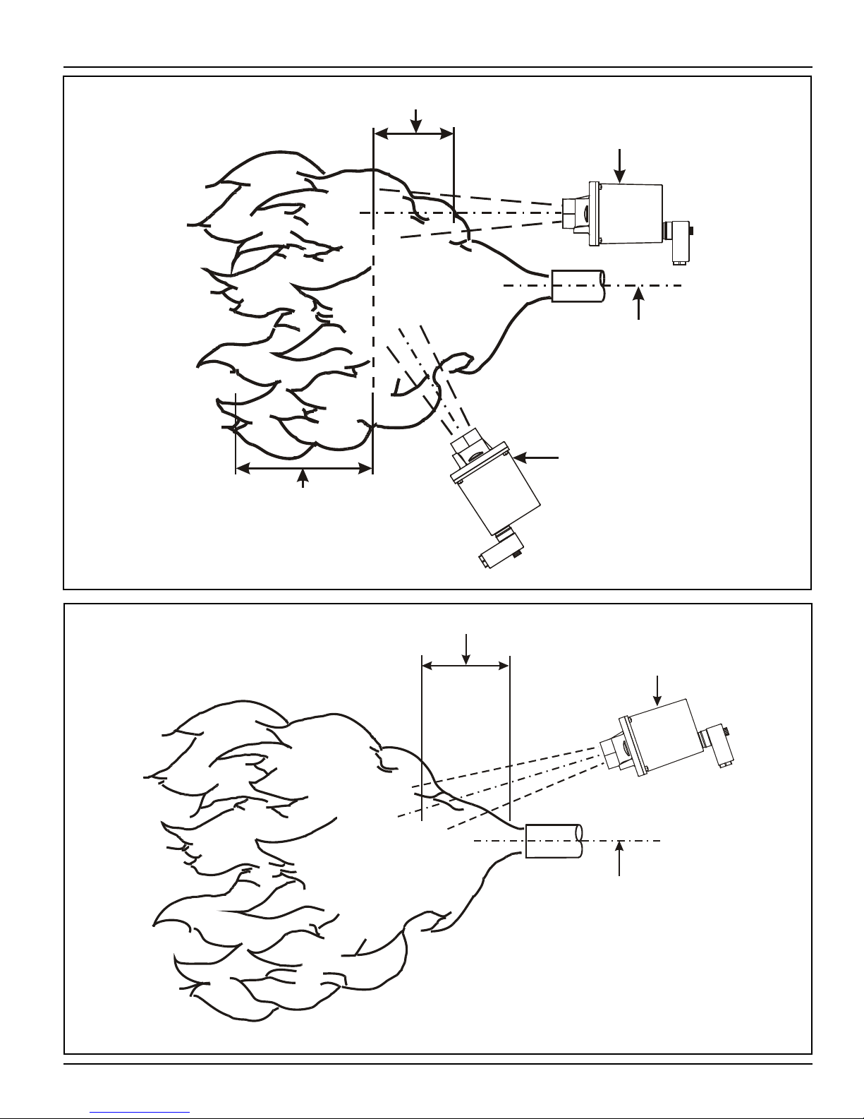
DETECTOR IN GOOD
SIGHTING POSITION
(PARALLEL SIGHTING)
BURNER NOZZLE
CENTERLINE
DETECTOR IN POOR
SIGHTING POSITION
LOW FREQUENCY
FLICKER ZONE
HIGH FREQUENCY
FLICKER ZONE
UV VIEWING
HEAD SIGHTED
ON UV ZONE
BURNER NOZZLE
CENTERLINE
UV RADIATION
ZONE
FIGURE 4: IR VIEWING HEAD LOCATION
FIGURE 5: UV VIEWING HEAD LOCATION
PAGE 15
Page 16
IRIS S55XX SERIES VIEWING HEADS APPLICATION MANUAL
VIEWING HEAD
BURNER NOZZLE NO. 1
NO. 1 FLAME
ENVELOPE
NO. 2 FLAME
ENVELOPE
VIEWING HEAD
BURNER NOZZLE NO. 2
HIGH FREQUENCY
IR ZONE
LOW FREQUENCY
ZONE
(LESS THAN 36Hz)
HIGH FREQUENCY
IR ZONE
2“ NPT NIPPLE TOE
IRIS M-701-2
SWIVEL MOUNT
IRIS R-518-12
1“ NIPPLE
IRIS VIEWING HEAD
1/2“ NPT PURGE
CONNECTION
BURNER FRONT PLATE
BURNER NOZZLE
CENTERLINE
QUICK DISCONNECT
CABLE CONNECTION
(SUPPLIED)
FIGURE 6: SIGHTING OPPOSED FIRED BURNERS
FIGURE 7: VIEWING HEAD MOUNTING
PAGE 16
Page 17
IRIS S55XX SERIES VIEWING HEADS APPLICATION MANUAL
PRESS BOTH A & B BUTTONS
“CAL?”
Calibrate Viewing
Head
?
N
N
“CALu”
Auto adjust
UV gain
?
N
NORMAL OPERATION
Calibrate UV
Y
Y
Calibrate IR
Y
“AuNN”
Adjust UV gain
0-99
Y
NORMAL OPERATION
N
FLOWCHART FOR S 550,
S550B PROGRAMMING
Y
N
DISCARD CHANGES
NORMAL OPERATION
Y
Keep new filter
selection
“ArFN”
Adjust IR filter
1-8
Y
Keep new UV Gain
“ANNN”
Adjust IR gain
0-699
N
DISCARD CHANGES
Y
Y
N
DISCARD CHANGES
Y
Keep new IR Gain
N
Y
Set Default
Values
“AdJ?”
Adjust Viewing Head
Settings
?
“dEF?”
Reset to Factory
Default
?
“CALr”
Auto adjust
IR gain
?
FLOWCHART FOR S550B PROGRAMMING
FIGURE 8: S550B PROGRAMMING FLOWCHART
PAGE 17
Page 18
IRIS S55XX SERIES VIEWING HEADS APPLICATION MANUAL
PRESS BOTH A & B BUTTONS
“CAL?”
Calibrate Viewing
Head
?
N
N
NORMAL OPERATION
Y
Calibrate IR
Y
Y
NORMAL OPERATION
N
FLOWCHART FOR S 552B PROGRAMMING
NORMAL OPERATION
Y
Keep new filter
selection
“ArFN”
Adjust IR filter
1-8
“ANNN”
Adjust IR gain
0-699
N
DISCARD CHANGES
Y
Y
N
DISCARD CHANGES
Y
Keep new IR Gain
N
Y
Set Default
Values
“AdJ?”
Adjust Viewing Head
Settings
?
“dEF?”
Reset to Factory
Default
?
“CALr”
Auto adjust
IR gain
?
FLOWCHART FOR S552B PROGRAMMING
FIGURE 9: S552B PROGRAMMING FLOWCHART
PAGE 18
Page 19

PRESS BOTH A & B BUTTONS
“CAL?”
Calibrate Viewing
Head
?
N
N
“CALu”
Auto adjust
UV gain
?
NORMAL OPERATION
Calibrate UV
Y
Y
“AuNN”
Adjust UV gain
0-99
Y
NORMAL OPERATION
FLOWCHART FOR S556B PROGRAMMING
Y
N
DISCARD CHANGES
NORMAL OPERATION
Y
Keep new UV Gain
N
Y
Set Default
Values
“AdJ?”
Adjust Viewing Head
Settings
?
“dEF?”
Reset to Factory
Default
?
N
IRIS S55XX SERIES VIEWING HEADS APPLICATION MANUAL
FLOWCHART FOR S556B PROGRAMMING
FIGURE 10: S556B PROGRAMMING FLOWCHART
PAGE 19
Page 20

IRIS S55XX SERIES VIEWING HEADS APPLICATION MANUAL
SPECIFICATIONS
ELECTRICAL
Input Power: 24VDC +10%, 100mA ( powered from Signal Processor)
ENVIRONMENTAL
Sealing: Viewing Head Housing NEMA TYPE 4
Ambient Temperature: -40° F to 122° F (-40° C to 50° C)
Case Temperature: -40° F to 140° F (-40° C to 60° C)
With S580 Fiber Optics -65° F to 572° F (-54° C to 300° C)
OPTICAL
Angle of View IR 1.0°
UV 3.0°
CABLE
Signal Processor to 4 conductor, #16AWG or #18AWG.
Viewing Head One wire shielded with braided shield for flame signal
such as IRIS Part Number C328
PAGE 20
 Loading...