

Page 1
IRIS MODEL S550 APPLICATION MANUAL
FLAME MONITORING SYSTEM
MODEL S550, S552, S556 VIEWING HEAD
APPLI CATION MANUAL
PAGE 1
Page 2

IRIS MODEL S550 APPLICATION MANUAL
TABLE OF CONTENTS
S550 GEN ERAL DE SCRIP TION............................2
S552 GEN ERAL DE SCRIP TION............................2
S556 GEN ERAL DE SCRIP TION............................2
COM PARI SON WITH OTHER MODEL 500 VH’s ...2
TECH NOL OGY USED IN THE S550......................3
CA BLE PREPA RA TION DWG ................................4
FI NAL AS SEM BLY (CA BLE) DWG .........................4
WIR ING OF VIEW ING HEAD .................................5
SIGHT ING OF VIEW ING HEAD .............................6
IR DE TEC TOR ........................................................6
UV DE TEC TOR .......................................................7
ORI FIC ING ..............................................................7
DE FAULT SET TINGS FOR THE S550 ...................8
BEF ORE MAK ING AD JUST MENTS.......................10
NEW P520/P522 FRONT PANEL...........................10
CALI BRAT ING THE S550.......................................10
EX AM IN ING RE SULTS GAIN SET TINGS CALIB ...10
CHECKING OR CHANG ING UV GAIN...................11
CHECKING OR CHANG ING IR FIL TER.................11
CHECKING OR CHANG ING IR GAIN ....................11
MAN UAL SETUP OF THE S550 .............................12
RE TURN TO DE FAULT SET TINGS ........................12
AN GLE OF VIEW ....................................................13
GEN ERAL COM MENTS .........................................13
TECH NI CAL HELP..................................................13
FIGURE 1 FRONT PANEL DRAW ING ....................14
WHERE S550 SET TINGS ARE STORED ..............8
AS SIGN ING DIFF S550 SET TINGS TO A&B .........9
US ING TWO VIEW ING HEADS PER AM PLI FIER .9
FIGURE 2 VH OUT LINE DRAW ING .......................14
FIG 3 FLOW CHART OF S550 PROGRAMMING ...15
FIG 4 FLOWCHART OF S552 PROGRAMMING ...16
FIG 5 FLOW CHART OF S556 PROGRAMMING ...17
PAGE 2
Page 3

IRIS MODEL S550 APPLICATION MANUAL
S550 GENERAL DESCRIPTION
The IRIS Model S550 is a state- of- the-art flame
monitor viewing head utilizing two types of
detectors, an IR (infrared) solid state and UV
(ultra violet) tube.
The S550’s work with the latest version of the
P520/P522 signal processors. Like other viewing
heads in the S500 family, the S550’s produce
output pulse rates propor tional to the flame signal
strength; the pulse rates are displayed at the front
panel of the signal processors. But, unlike the
other members of the S500 family, certain
parameters in the S550 viewing head can be
selected or adjusted remotely from the front panel
of the P520/P522 signal processors. The
parameters are:
a) UV gain 0-99
b) Fil ter Se lec tion 1-8
c) IR gain 0-699
Once adjusted, the new parameters are stored in
EEPROM in the signal processor. If power is
removed from the signal processor which powers
the viewing head and then reapplied, the signal
processor then automati cally re-sends the stored
parameters out to the S550 viewing head. In
addition, at the front panel of the signal processors
the operator may also select “CAL”, a semiau to matic mode which will help to speed up the S550
setup. This is explained in detail in the section
called CALIBRATING THE S550 on page 10. Also
notice the FLOWCHART OF S550 PROGRAMMING ,
Fig ure 3 on page 15. Thus the S550 is a dual sensor viewing head where the gain and filter
selec tions are adjusted remotely and stored in the
P520/P522 signal processors.
S552 GENERAL DESCRIPTION
The S552 is for IR sensing only. It is basically an
S550 without a UV capability. The P520 or P522
will be aware of which viewing head of the S550
family is connected to it so that only those adjust ments which are appro priate to the S552 will be
made available to the operator. These adjust ments
apply to the S552:
When it comes to features like CAL, which will be
described later, the operator is only given those
choices which are appro priate. For example, he
does not have to choose between calibrating with
the UV sensor or the IR sensor; in CAL he is only
offered the choice of calibrating with the IR sensor
or not. This is shown in the FLOWCHART OF S552
PROGRAMMING
, Fig ure 4 on page 16.
To keep the manual straightforward only the
operation of an S550 is described. If one has an
S552 one should simply disregard references to
those features of the S550 which are UV-related.
S556 GENERAL DESCRIPTION
The S556 is for UV sensing only. It is basically an
S550 without an IR capability. The P520 or P522
will be aware of which viewing head of the S550
family is connected to it so that only the
adjustment which is appro priate to the S556 will
be made available to the operator:
a) UV gain 0-99
When it comes to features like CAL, which will be
described later, the operator is only given those
choices which are appro priate. For example, he
does not have to choose between calibrating with
the UV sensor or the IR sensor; in CAL he is only
offered the choice of calibrating with the UV
sensor or not. This is shown in the FLOWCHART
OF S556 PROGRAMMING
, Fig ure 5 on page 17.
To keep the manual straightforward only the
operation of an S550 is described. If one has an
S556 one should simply disregard references to
those features of the S550 which are IR-related.
COM PARI SON WITH OTHER MODEL 500
SE RIES VIEW ING HEADS
The S550 uses a Germanium sensor for IR
detection like an S511 and uses a high- voltage
vacuum tube sensor for UV detection like the
S506’s, but both sensors are in the same housing
in the S550. The pulses from the UV and IR
sensors are summed inter nally into a single pulse
stream out to the signal processor.
a) Filter Selection 1-8
b) IR gain 0-699
PAGE 3
A dual-LED indicator is used to indicate the pulse
rate out of the S550. It is visible at the rear of the
Page 4
IRIS MODEL S550 APPLICATION MANUAL
viewing head housing. (See Fig. 2). For every 128
pulses from the UV sensor it emits one green
pulse; for every 128 pulses from the IR sensor it
emits one red pulse. With a count rate of 1200
displayed at the signal processor the LED will
flash 9 or 10 times per second. This is very useful
for aiming and sighting the viewing head. One can
readily distin guish differ ences in pulse rates at the
LED and use this indicator to adjust the sighting to
obtain a maximum pulse rate at the LED and
therefore a maximum reading at the signal
processor.
The S550 differs from older models in that the
gain for each sensor and the selection of the filter
for IR may be set remotely through the front panel
of the P520/P522 signal processors.
Also the earlier IR sensitive family members had
only 4 high pass filters to choose from; the S550
has 8:
S511 & S512 S550
LL 36 Hz 1 16 Hz
L 71 Hz 2 24 Hz
M 105 Hz 3 33 Hz
H 186 Hz 4 52 Hz
5 75 Hz
6 100 Hz
7 155 Hz
8 215 Hz
TECH NOL OGY USED IN THE S550
The UV and IR sensors in the S550 share a
common optical axis efficiently by using a unique
dichroic beamsplitting mirror. Over 80% of the
ultra violet light is reflected off the surface of the
45 de gree mirror and yet over 80% of the infrared
radiation is trans mitted through the beamsplitting
mirror.
The electronics in the S550 is designed using
highly reliable surface mount technology.
The high pass frequency responses of eight
different filters in the S550 and S552 are imple mented compu ta tionally in a high- performance,
CMOS micro con troller inside the viewing heads.
This approach reduces the parts count and
PAGE 4
Page 5
IRIS MODEL S550 APPLICATION MANUAL
PAGE 5
Page 6

IRIS MODEL S550 APPLICATION MANUAL
increases the reliability of the S550 compared to
earlier approaches that used discrete analog
compo nents to implement four active filters. The
micro con troller also handles commu ni ca tions
with the P520/P522 signal processors.
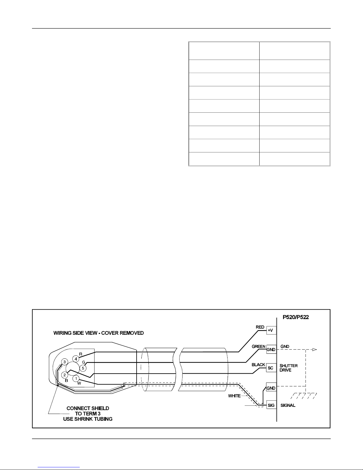
WIRING OF VIEWING HEAD
Wiring of the viewing head is made to the
terminals on the rear backplane PC board (or
output module) on the P520 signal processor and
is made to the terminals on the lower right side of
the P522. These terminals are listed functionally
as follows:
TERM DE SCRIP TION
GND
+V
SC
SIG
Power Ground
+24 VDC power to view ing head
Shut ter Drive Sig nal to V.H.
Flame Sig nal from V.H.
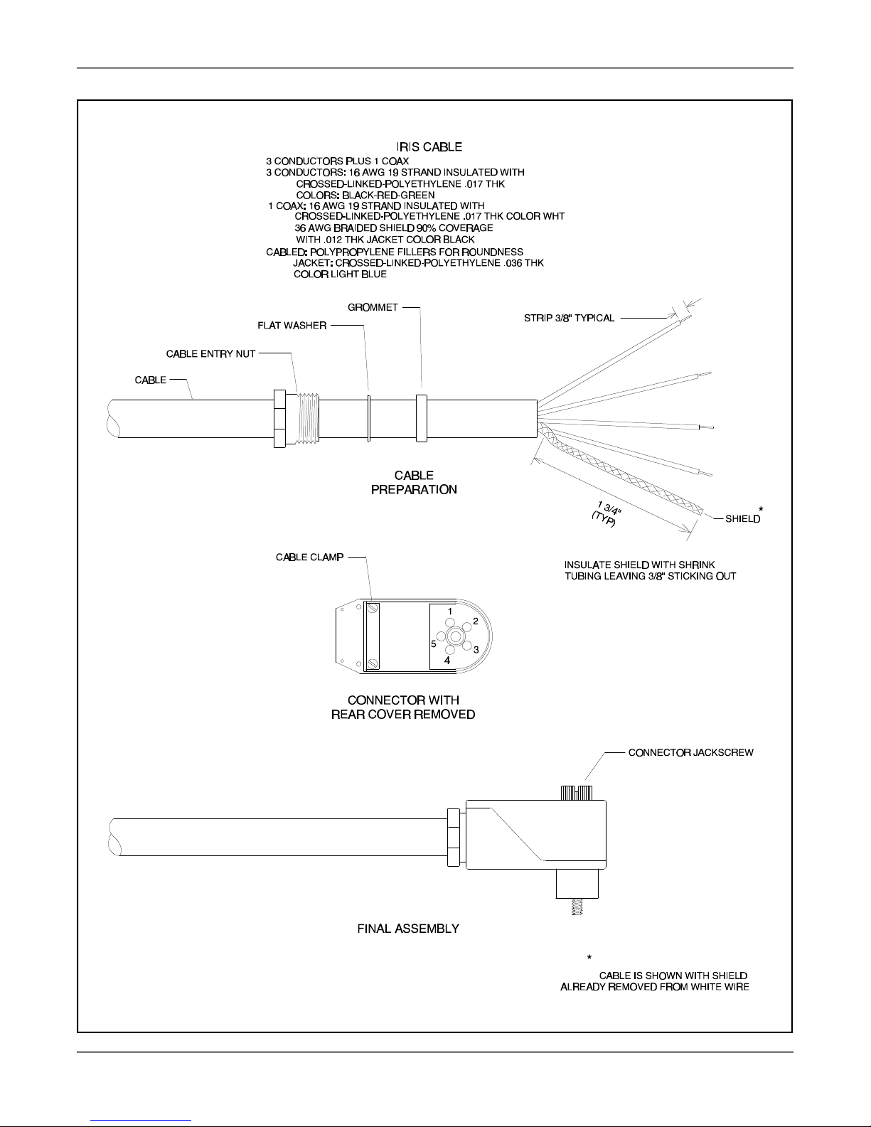
1. Strip 2 inches of the cable outer cover from the
cable removing any cello phane wrap or filler
material and strip the insulation from the
shielded wire (if insulated over shield) a full 2
inches to expose shield.
2. Slide the shield back until a bulge develops
close to where the wire exits the cable outer
covering.
3. Carefully spread a few strands of the shield at
the bulge (making sure not to break any
strands) to cre ate an opening and slip wire out
of shield through opening.
4. Carefully return shield to original shape and
length by pulling gently, then cover with
plastic shrink tubing to prevent shorts.
5. Slide nut (with threads toward the cable end),
the washer and the grommet onto cable
approxi mately 6 inches.
SIG GND
Sig nal Ground
The figures on the previous pages show a four
conductor cable to the viewing head. Note that the
flame signal wire going to terminal SIG is
shielded and the shield is termi nated at both ends
of the cable(SIG GND).
The standard IRIS Model 500 cable is desig nated
as part number C328. It is specified as a four
conductor cable with one wire shielded. The
shield is used as the signal ground wire which
goes to terminal SIG GND on the P520/P522 and
to pin 3 on the viewing head plug. The shield is a
braided type for this appli cation (a foil type shield
should not be used) so that a solid signal ground is
maintained. This signal ground shield is also the
self- checking or shutter drive circuit return path. It
is recom mended that the IRIS cable be used for all
appli ca tions. Ref er to the diagrams on pages 3 and
4 for wiring details.
Connec tions of the IRIS cable to the viewing head
plug should be done as follows:
Remove the plug from its packaging and layout
the components.
6. Slip the cable through the bottom opening of
the connector making sure that the cable outer
jacket is secure under the cable clamp and
tighten the two screws on the cable clamp.
7. Reassemble the grommet, flat washer, and
cable entry nut and tighten.
8. Bef ore wiring to connector, strip each wire
3/8" as shown in assembly drawing on pre vious page.
9. Proceed to wire the connector as follows: (Ref er to drawings on page 3 for terminal
locations.)
Connect viewing head signal wire (the shielded
wire) WHT to terminal No. 1 by inserting into
opening and then tight ening the retaining screw.
Connect the self- checking signal wire BLK to
terminal No. 2. Connect the signal ground shield
from WHT wire with shrink tubing to terminal
No. 3. Connect + 24 VDC power wire RED to
terminal No. 4. Connect the power ground wire
GRN to terminal No. 5. Assemble the back of the
plug and insert jackscrew through plug assembly.
PAGE 6
Page 7

IRIS MODEL S550 APPLICATION MANUAL
The cable wiring on the other end going to the
signal processor is easier to do. The cable should
be prepared in a similar way to the plug end
particu larly the shield from the WHT wire. Make
sure the shield doesn't touch the other terminals.
SIGHT ING OF VIEW ING HEAD
The sighting of the viewing head should be
parallel to the cen terline of the burner in the
direction of the flame. The sight pipe should be
mounted as close to the cen terline as possible; the
idea is to sight along the flame rather than across
the flame. This will help prevent drop outs of the
flame under changing load condi tions.
Utilizing a sighting or the sight pipe aimed at the
root of the flame (where the turbulent combustion
air mixes with the flame) is a good starting point
for optimizing the sighting. Using a swivel mount
to “zero-in” on the highest signal will assure
maximum performance. Make sure the diameter
of this sight pipe is large enough to allow a
reasonable field of view. The S550’s has two
angles of view, one for the IR detector, which is
1.0° and one for the UV detector which is about
3.0°; this trans lates into a circle of view that
varies with the viewing distance as shown in the
following table.
Dis tance Dis tance
ft inches inches inches
2 24 .64 1.3
3 36 .73 1.9
6 72 1.45 3.8
12 144 2.90 7.6
18 216 4.35 11.4
Di ame ter of
IR view
Di ame ter of
UV view
Detecting flame in a sulfur recovery unit can
present problems for flicker type flame monitors
such as the IR detector in the S550 viewing head.
The IR detector will detect natural gas used for the
warm-up of the reactor. Usually the combustion
air is turbulent enough to cause a good flicker
signal. When the sour gas is intro duced and the
natural gas shut down the flame signal may drop
off or drop out entirely. The reason for this is that
there is a complete change in the flicker content
for the existing viewing head sighting. If this is the
case, then one should try and optimize the flame
signal for the sour gas by “zeroing-in” on this
flame, not the warm-up burner.
After optimizing the sighting for the sour gas one
may find that the signal level is too low on the
natural gas. One should then try the UV detector
for this appli cation. It may be necessary to use two
sets of set points for flame ON and flame OFF, one
set for proving and detecting the natural gas flame
and the other for proving and detecting the sour
gas flame. The switch-over from Channel A to
Channel B should be done when removing the
natural gas burner. This can be imple mented from
the burner control system. This switch-over and
the use of Channels A and B with their
independent settings is explained in the section
ASSIGNING DIFFERENT S550 SETTINGS TO
CHANNEL A and B on page 9.
IR DETECTOR
The IR detector responds to the flicker content in
the flame. Flame flicker is caused by the
combustion, or forced air injected into the flame.
This combustion air can be mixed with the fuel
(pulverized coal) or can be intro duced separately.
In either case, forced air at high velocity is intro duced in such a way as to aid the combustion
process. This air is usually made turbulent by
causing it to swirl with spin vanes located in the
burner barrel.
Flame flicker is created when this turbulent air
mixes with the flame. It is composed of random
frequencies from zero Hz to over 2,000 Hz. The
amount of high frequency flicker (above 200 Hz)
is dependent on the fuel and burner. The amplitude
of the flicker frequencies always follows an
exponential curve with zero frequency having the
highest amplitude and the higher frequencies the
lowest. The amplitude level of the higher
frequencies is usually 40dB down (factor of 100)
from zero Hz or DC.
PAGE 7
Page 8

IRIS MODEL S550 APPLICATION MANUAL
The S550 and S552 respond to flicker frequencies
16 Hz and above. They ignore the lower
frequencies so it is important to sight the viewing
head on the highly turbulent portion of the flame
that contains these higher frequencies. One can
predict where these higher frequencies will be by
examining the burner with regard to where the
flame envelope begins and where the turbulent air
enters this flame. This spot can be chosen by
examining the drawings of the burner but it is
better to do this empiri cally by using a swivel
mount on the viewing head.
UV DETECTOR
The S550 viewing head with its dichroic mirror
and UV tube have a combined spectral response of
190-215 nm. The UV tube is inher ently a pulsing
device, that is, the power supply has been
designed so that the tube emits pulses when UV
radiation is present. Its output is pulse stream of
randomly spaced pulses whose average rate is
propor tional to the UV radiation present.
The very narrow spectral response of the S550
viewhead makes it ideal for discrimi nating
between flame and glowing refractory and other
burners. How ever, because the tube responds to
only the very short wavelengths, problems can
occur because this radiation is easily absorbed and
masked, for example with pulverized coal, by
unburned fuel or other impurities in the fuel. Sour
gas (H2S) will readily absorb these short 200nm
wavelengths as well as other waste fuels resulting
in a dropout of the flame signal. Even standard
glass will absorb this wavelength, hence, the
necessity of using a quartz lens with this viewing
head.
In general, the UV viewing head will work well on
natural gas flames. It will respond to oil flames but
with a lower signal level. The sighting for both oil
and gas flames should be parallel to the axis of the
burner and aimed at the root of the flame, as with
the IR detector. (See pre vious section IR
DETECTOR.
) Photo graphs of gas and oil flames
using visual and UV-sensitive film show clearly
that the UV zone is much smaller than the visible
zone, and the highest UV intensity occurs near the
flame root. In addition, the zone of higher UV
intensity does not overlap the same zones of
adjacent or opposing burners so that, with proper
sighting, discrimi nation is predictable.
As a general rule, the sighting of the S550 when
using the UV detector, will be more likely a “line of- sight” than the IR flicker detector which will
read flame signals bouncing off the side of the
sight pipe and other “reflectors”. Sometimes the
reading with the IR detectors can be greater with a
reflected signal than the direct line of sight. The
UV detector on the other hand, will have to be
aimed at the part of flame that has the highest
concen tration of UV, which usually is at the root
of the flame (at the throat of the burner) and in a
very narrow region. The angle of view of the S550
UV is somewhat wider than the S550 IR but this
does not offset the fact that the UV radiation
present is from a very small region.
This small region emitting UV is not the case
how ever, for low NOX gas burners. The UV
radiation is usually much less in intensity and
spread out with this type of burner, such that one
gets relatively high readings from all over the
furnace when many burners are on. This is
particu larly true when flue gas recir cu lation is
used. There will be, how ever, a relatively stronger
signal near the “root” of the flame and this more
intense spot should be located during the aiming
or sighting process. This “root” or intense spot
may be further out than with the standard gas
burner so it is imperative that one use a swivel
mount when making these sighting adjust ments.
Also, another factor one must con sid er when
aiming the viewing head is the load condition of
the boiler. The flames from a burner can be
radically different at different loads. This is one of
the reasons for trying to pick a sighting initially
that will minimize this changing flame at different
loads. If the flame moves further out at higher
loads then the parallel to the burner axis sighting
will be the best. Using a large diameter sight pipe
with a swivel mount is recom mended for all
instal la tions on large multi burner boilers.
ORIFICING
There are many appli ca tions where the burner
flames can be so bright they will saturate the S550
sensors. With these condi tions orificing the
PAGE 8
Page 9

IRIS MODEL S550 APPLICATION MANUAL
viewing head sight path will greatly improve the
performance, particu larly with regard to discrimi nation between flames. Although saturation is less
likely with the Ge (germanium) IR photo de tector
used for the S550 as compared to prior model
viewing heads using the PbS (lead sulfide) type
photo de tector, the possi bility should not be
ignored. Saturation is more prob able with large
power utility boilers where the burners are very
large and relatively close to one another. If one
cannot look at the flame with the naked eye
without it hurting, then orificing should be used.
This eye test works for incan descent type flames
such as oil and coal but will not be valid for
natural gas flames.
Orificing may help improve the discrimi nation
charac ter istics for the UV detector as well as the
IR. The UV tube in the S550 is not likely to
saturate; how ever, orificing will usually improve
the discrimi nation ratio for large size burners.
An orificing disc is simply a metal disc with a
circular hole in the cen ter which is placed directly
in front of the lens. Four orificing discs are
available with cen ter hole diameters of 3/8, 1/4,
3/16 and 1/8 inch. These discs are installed with
retaining rings in the flange at the edge of the 1/2
inch NPT female pipe thread for the purge air. An
internal type retaining ring is first installed by
positioning a ring in the machined groove inside
flange opening from the housing side. The
orificing disc is then inserted. Use a second
retaining ring to hold it in place so that it is
sandwiched tightly between the two retaining
rings.
Usually an orificing disc with a larger diameter
hole is tried first. There will be a reduction in the
signal level so if the associated S550 and signal
processor has been previ ously calibrated it will be
necessary to calibrate the processor again so that
the gain settings will be correct. If the discrimi nation is still not satis factory then try an orificing
disc with a smaller diameter hole.
Generally speaking, orificing should always be
considered when the burner(s) are large (50K lbs
of steam and up), particu larly when the IR
detector is used which would be the case for oil or
pulverized coal.
The following table shows the signal reducing
charac ter istics of the different orificing discs:
Ap er ture
Hole
1" 2 1
3/8" 5.3 1/8
1/4" 8 1/16
3/16" 10.7 1/32
1/8" 16 1/64
Fn
(f Stop)
Rela tive light
pass ing power
DEFAULT SETTINGS FOR THE S550
A new P520 / P522 will send the S550’s default
“Gains” as follow:
UV Gain = 32 (out of 0-99 range)
Fil ter = Fil ter 3 (high pass above 33Hz)
IR Gain = 451 (out of 0- 699 range)
These are nominal settings that should allow for
initial sightings and adjust ments. Both UV and
IR sensors are active in the default mode. They
are the same settings that will be active in an S550
when used with an older version of the P520/P522
or with an M502 signal processor. If the settings
for the S550 have been changed from the default
settings the operator may reset the “Gain” to the
factory default from the P520 / P522 control
panel. (See Return to Default Settings on Page 12.)
WHERE S550 SETTINGS ARE STORED
Settings for the S550s are stored in EEPROM in
the particular P520/P522 which made the adjust -
ments. On subse quent power-up cycles the
P520/P522 will send out the settings again to the
S550 viewing head. In fact, if one S550 is
exchanged with another one, the P520/P522
cannot tell one S550 from another and will send
out the same settings. This simplifies field
replace ments; all S550’s are made to very close
PAGE 9
Page 10

IRIS MODEL S550 APPLICATION MANUAL
tolerences, so any other S550 will work virtually
the same as the one it replaces.
NOTE: the S550 is designed to work only with
newer P520/P522 signal processors. How ever,
besides working with newer signal processors,
S552’s and S556’s are designed to work also with
older P520/P522 and M502 signal processors;
with these they will operate at their default gain
settings.
AS SIGN ING DIF FER ENT S550 SET TINGS
TO CHAN NEL A AND B
With the P520/P522 an operator may assign one
group of S550 settings to Channel A and another
group of S550 settings to Channel B, just as he
would assign different Flame ON and Flame OFF
set points to Channels A and B. How one may
store settings for each channel in the P520/P522
will be briefly reviewed.
If the CHAN SEL input to the P520/P522 is open
or de-energized, then the Channel A lighted push button on the front panel will be continu ously ON.
If a voltage of 7.5V to 30V is applied across the
two CHAN SEL inputs, then Channel B will be
selected and the Channel B lighted push button
will be continu ously ON. When Channel A is
selected, any P520/P522 parameters changed (this
includes Flame ON and Flame OFF set points and
the analog gain of the P520/P522 as well as the
gain and filter selection for the S550) will be
stored for use when Channel A is selected.
Similarly, when Channel B is selected any
P520/P522 changes are stored for use when
Channel B is selected. When the CHAN SEL
input is changed, the P520/P522 changes the set
points in use accord ingly and sends the appro priate gain and filter selec tions to the S550
viewing head.
In the P520/P522 there is a way to observe and
change settings for the channel which is not
selected: simply press the other channel push
button - it will blink indicating that the selection is
temporary - and then proceed as if the CHAN SEL
input had changed. This method is available for
examining or changing Flame ON and Flame OFF
set points and other settings in the P520/P522. The
same pro ce dure applies to manually changing
S550 settings when the desired channel is not
selected: press the push- button for the desired
channel and then proceed. During the process of
examining or changing the S550 settings, with the
Channel A and B (NO and YES) push buttons, the
red LED for the channel which the changes apply,
will be blinking.
One should visually check which channel push
button is lighted when the S550 settings are being
reviewed or changed. It is easy to get into the S550
CAL modes with the wrong channel selected. For
example, if the Channel A LED is on or blinking
and one intends to press both buttons at the same
time to enter the CAL mode for Channel A, but,
instead, one presses the Channel B push button
well bef ore the Channel A push button, the
P520/P522 will think that the operator has
selected Channel B then subse quently pressed
both push buttons. Then, in the CAL modes, the
red LED for Channel B will be blinking, which is
not what was intended. If this happens, one should
get out of the CAL mode, select the desired
channel, and press both push buttons again to
reenter the CAL mode, but this time pressing both
push buttons at approxi mately the same time.
USING TWO VIEWING HEADS PER
AMPLIFIER
Two viewing heads can easily be hooked up to the
same amplifier using the V.H. A and V.H. B
inputs. To permit this to work properly the P520
or P522 should be wired so that a 24VDC channel
select signal will be applied simul ta ne ously to the
coil of the VH select relay and to the channel
select input. Then, when the channel selection is
changed, the alternate set of data inputs from
viewing head B will be switched into the signal
processor by the VH select relay and the processor
will apply a different group of set points and gains
in response to the A/B Channel switch.
There is no restriction on how viewing heads may
be mixed between the two channels. One can
have an S550 on one channel and an S511 on
another, or an S552 on one channel and an S556
on another, or any combination. Of course, the
earlier 500 series viewing heads - Models S506,
S511 and S512 - are not adjustable remotely as the
S550 family of viewing heads are. The P520 or
PAGE 10
Page 11

IRIS MODEL S550 APPLICATION MANUAL
P522 signal processors will continue to work as
they have in the past with an earlier 500 series
viewing head when the channel with that viewing
head is selected.
BEFORE MAKING ADJUSTMENTS
Bef ore making any adjust ments to the S550 one
should optimize the flame signal strength by
aiming the viewing head at the most intense part
of the flame as explained in the two pre vious
sections IR DETECTOR and UV DETECTOR. This
operation should be done with the default settings.
NEW P520/P522 FRONT PANEL
Please ref er to Fig. 1 at the end of this manual
which shows the current front panel for the
P520/P522. The words NO , CAL and YES are
shown here in black but are actually red. This
latest version of the P520/P522 signal processors
may be used to commu nicate with the S550
viewing heads as described below.
CALIBRATING THE S550
The S550 calibrate feature is designed to aid with
the setup of the S550. It is basically an auto mat ic
gain adjustment for the selected sensor; the gain
for the sensor not selected is set to zero. CAL tries
to bring the displayed count to about 1200. It also
automati cally sets the Flame ON set point at 800
and Flame OFF set point at 600, which control the
Flame Relay. The filter selection remains
unchanged.
3) Bring the firing rate of the burner to a low fire
condition.
4) If the flame relay has not pulled in, adjust the
flame on & off set points so it does pull in.
5) Decide whether to calibrate using the UV or
IR sensor. See earlier sections on IR
DETECTOR and UV DETECTOR.
At the front panel of the P520/P522 press both
A and B push buttons simul ta ne ously. The
display will respond with “CAL?”. Press YES.
The display will then show “CALu”. Press
YES to calibrate the UV response or press NO.
If NO is pressed the display will show
“CALr”. Press YES to calibrate the IR
response. (Pressing NO will return the
P520/P522 to normal operation, exiting the
S550 CAL mode.) The P520/P522 will
automati cally adjust the gain for the selected
sensor; this takes a few seconds. If this
adjustment is successful the display will show
“----”, and the P520/P522 will return to
normal operation, displaying a reading of 1100
to 1300. But if the signal input is too low the
P520/P522 will display “2-Lo”. Press the
RESET button to return to the pre vious
settings. If the signal level is too high, the
display will show “OriF”. (See section on
ORIFICING.) Press RESET to return to the pre -
vious settings.
Calibration Pro ce dure:
1) Make a quick initial adjustment of the sighting
of the viewing head, trying to obtain a high
pulse rate. Red pulses from the LED indicate
that the IR sensor is producing output pulses;
green pulses indicate that the UV sensor is
producing output pulses.
2) Be sure that the external input for CHAN SEL
is properly set for the channel about to be
calibrated and that the channel LED is on
continu ously. When Using the calibrate
feature one does not have the option of
working with the channel that is not selected
by the external input.
PAGE 11
6) If step 5 was successful, re-aim the S550 for a
final adjustment using the LED to adjust the
viewing angle for a maximum pulse rate. Then
redo the CAL sequence as in step 5). The
Flame Relay will remain pulled-in. The
display should show a reading between 1100
and 1300.
7) Review the settings for F.F.R.T. And TIME
DELAY ON and adjust if necessary.
EXAMINING THE RE SULTS OF GAIN
SET TINGS FROM CALIBRATION
The gain settings deter mined automati cally by the
forgoing calibration pro ce dure may be viewed by
following the steps below for checking or
changing the UV and IR gain. Changes to these
Page 12

IRIS MODEL S550 APPLICATION MANUAL
settings, of course, may be made. The auto mat ic
calibration process is not sacred; it only finds gain
values. The user may change these, if he wishes,
to suit his needs. For example, one may wish to
increase the gain so the nominal displayed value is
1500 instead of 1200.
Note that the calibration pro ce dure sets the gain of
the sensor not being used to zero, but one can
adjust the gain of the unused sensor so the S550
responds to both sensors. The S550 sums the
sensor outputs.
CHECKING OR CHANGING UV GAIN
At the front panel of the P520/P522 press both A
and B push buttons simul ta ne ously. The current
numerical data on the 4 digit display will be
replaced with “CAL?” meaning, “Do you wish to
Calibrate?” If you press YES you will enter the
Calibration mode described in the pre vious
section. Press NO to enter the Adjust mode. The
display will show “AdJ?” meaning, “Do you wish
to make manual adjust ments?” If you do, press the
button near YES, which is the B push button. The
display will show “AuNN” where NN is the
current UV gain with the range 00 - 99. A gain of
00 turns off the sensor. To change the UV gain use
the up or down push buttons. If you then press
YES the new value will be stored; if you press NO
(Channel A push- button) the new value will be
ignored.
CHECKING OR CHANGING IR FILTER
You next have an oppor tunity to change the IR
filter. The display will show “ArFN” where N is
the current filter selected ranging from 1 to 8. Use
the up and down push- buttons to change the filter
if you wish. See COMPARISON WITH OTHER
MODEL 500 SERIES VIEWING HEADS for a listing
of the high-pass frequencies for these filters. Press
YES to accept a new filter value or NO to ignore
any changes you may have made.
For further infor mation please call the factory or
contact IRIS Systems Inc. See page 13 for contact
infor mation.
CHECKING OR CHANGING IR GAIN
You now have an oppor tunity to make a final
adjustment of the IR gain. After the filter
selection, the display will show “ANNN” where
NNN, the IR gain, ranges from 000 to 699. The up
and down push- buttons can be used to change the
IR gain. Changed values can be accepted by
pressing YES or ignored by pressing NO. If the
S550 settings are changed, the display will show
“----” indicating that the values are stored in
EEPROM bef ore continuing with the normal
numerical display.
If you do change the IR gain you may be surprised
to see the displayed gain values “jump” as you
scroll through them. As you increase the gain from
zero you will see this sequence:
000 - 099
150 - 199
250 - 299
350 - 399
450 - 499
550 - 599
650 - 699
The two least significant digits are linear gain
multi pliers; e.g., from 150 to 199 is a 99/50
increase in gain. But the most significant digit is
nonlinear; with each step change in the most
significant digit, the gain doubles. For example, a
setting of 250 has twice the gain as a setting of
150. Now it is possible to see why, as the gain is
increased from 150 to 199 the next step is to 250;
an increase from 150 to 199 is an increase of
99/50, which is a gain increase of almost 2, but the
next step to 250 is to a gain increase, theore ti cally,
to exactly 2. This relationship is true of all the
gains to 699.
It is recom mended that the #3 default filter (33Hz
cutoff) be used for all of the initial setup proce dures described in this manual. Further infor mation on how these filters can affect the discrimi nation ratio is found in the P520 APPLI CATION
MANUAL and in the P522 APPLI CATION MANUAL
in the section MULTI BURNER REQUIRE MENTS.
The two least significant digits can be used below
050 down to 000; 000, of course, selects a gain of
zero (which turns OFF the sensor). When the
display is ramped down from 699 the following
sequence will be seen:
PAGE 12
Page 13

IRIS MODEL S550 APPLICATION MANUAL
673 - 637
573 - 537
473 - 437
373 - 337
273 - 237
173 - 137
073 - 000
This approach makes a wide range available for
gain multi plier changes using the two least
significant digits. For example, over a range of
137 to 199 the gain is changed by a ratio of 99/37.
It is advan ta geous for moderate changes in gain to
change only the gain multi plier digits because the
response to these changes is very linear. When
changes are made in the most significant gain
digit, the gain change is not always exactly an
ideal 2:1 step change.
MAN UAL SETUP OF THE S550
The steps below for manual setup should result in
the P520 or P522 displaying a reading close to
1200 with flame on. This pro ce dure should pro vide similar gain settings for each selected sensor
as in the CALIBRATION pro ce dure described
earlier.
1) Bring the firing rate of the burner to a low fire
condition.
stays the same or actually increases, the S550
is saturated. Continue reducing the gain in
steps of 100 until the displayed reading is
reduced. Then set the gain so the reading is in
the 1000 to 1400 range. If the IR sensor was
not saturated one can skip para graph 5) below.
5) If the S550 was saturating one should check
the aiming of the S550 again using the LED
on the back of the housing to adjust the
viewing angle of the head for a maximum
pulse rate. If the LED pulse rate is then too
high (the LED is ON almost continu ously)
change the gain once more by using the Adjust
Mode pro ce dure to get a reading in the 1000 to
1400 range. Then maximize the pulse rate by
re-aiming the S550 viewing head. This pro ce dure of optimizing the sighting and adjusting
the gain may have to be done more than one
time to be assured that the S550 is properly
setup.
6) If the UV sensor has been chosen adjust the
gain (00-99) using the Adjust Mode so the
displayed reading is close to 1200. The UV
sensor is not likely to saturate but if the flame
signal readings are very high on low gain
settings then one should orifice the sighting.
See section ORIFICING.
2) Be sure that the external input for CHAN SEL
is properly set for the channel calibration (A or
B) that is currently being set and the channel
LED is ON continu ously.
3) Decide whether to setup the S550 using the
UV or IR sensor bef ore aiming the viewing
head. In some flames the best UV reading of
the flame envelope may be found at a different
location from the best IR reading. See earlier
sections IR DETECTOR and UV DETECTOR .
Use the Adjust Mode (“AdJ?”) pro ce dure for
the S550 described above and set the gain for
the sensor not being used to zero.
4) If the IR sensor is being used, bef ore final
aiming but with a typical reading on the
display, verify that the S550 is not saturated by
reducing the IR gain by 100. The displayed
reading should be reduced by roughly 1/2. If it
PAGE 13
7) Set or at least check the Flame ON and Flame
OFF set points. If they are still at the factory
default values (Flame ON at 800 and Flame
OFF at 600) they may be satis factory as they
are. If the Flame ON reading is less than 1200
the Flame OFF setting should be propor tion ately less.
8) Review the settings for F.F.R.T. and TIME
DELAY ON and adjust if necessary.
RE TURN TO DE FAULT SET TINGS
There are three major branches on the decision
tree after one gets into the S550 setup by pressing
the A and B push buttons. Ref er to Fig. 3 at the
end of this manual. That is, if one says NO to
“CAL?”, one is asked if one wishes to do adjust. If
one says NO to “AdJ?”, one is asked if one wishes
to go back to the default settings. If one says NO
to “dEF?”, then the P520/P522 and S550 continue
Page 14

with normal operation. If one says YES to
defaults, then the original default settings are
stored for the selected channel overwriting the
pre vious S550 settings for that channel.
ANGLE OF VIEW
The angle of view for S550 viewing head utilizing
the IR detector will be the same as the S511
because the Ge photo de tector element is 1mm in
diameter which results in an angle of 1.0°. When
using the UV detector the angle of view will be the
same as the S506 which is about 3.0 °. See section
SIGHTING OF VIEWING HEAD for details.
GENERAL COMMENTS
It will be obvious to the user of this new
innovative product that this is the ultimate state of- the-art flame monitor. The way it works has
been described only in a general sense and
obviously the algorithms imple mented by the
embedded controller software are proprietary and
will not be made pub li c. Any existing P520 or
P522 signal processor can be upgraded to an S550
compatible processor by changing the controller
chip and the front panel.
IRIS MODEL S550 APPLICATION MANUAL
TECH NI CAL HELP
For technical help in applying this product please
contact:
Factory and Repairs:
IRIS Systems Inc.
(JB Systems, Inc.)
4944 - 113th Avenue North
Largo, FL 33760
Tel: 727 545-3900
Fax: 727 547-9589
Sales and Appli ca tions Support:
IRIS Systems Inc.
7583 Vantage Placey
Delta, BC V4G 1A5
Tel: 604 584-4747
604 538-5972
Fax: 604 581-9790
1-800-667-IRIS
PAGE 14
Page 15

IRIS MODEL S550 APPLICATION MANUAL
Figure 1
PAGE 15
Figure 2
Page 16

IRIS MODEL S550 APPLICATION MANUAL
PAGE 16
Fig ure 3
Page 17

IRIS MODEL S550 APPLICATION MANUAL
PAGE 17
Fig ure 4
Page 18

IRIS MODEL S550 APPLICATION MANUAL
Fig ure 5
PAGE 18
Page 19

IRIS MODEL S550 APPLICATION MANUAL
PAGE 19
5 June 1997
 Loading...